EP3798650A1 - Insulation diagnosis and positioning method for insulated tube-type bus bar - Google Patents
Insulation diagnosis and positioning method for insulated tube-type bus bar Download PDFInfo
- Publication number
- EP3798650A1 EP3798650A1 EP20711768.0A EP20711768A EP3798650A1 EP 3798650 A1 EP3798650 A1 EP 3798650A1 EP 20711768 A EP20711768 A EP 20711768A EP 3798650 A1 EP3798650 A1 EP 3798650A1
- Authority
- EP
- European Patent Office
- Prior art keywords
- grounded
- segment
- ground
- insulated bus
- bus pipe
- Prior art date
- Legal status (The legal status is an assumption and is not a legal conclusion. Google has not performed a legal analysis and makes no representation as to the accuracy of the status listed.)
- Granted
Links
Images


Classifications
-
- G—PHYSICS
- G01—MEASURING; TESTING
- G01R—MEASURING ELECTRIC VARIABLES; MEASURING MAGNETIC VARIABLES
- G01R31/00—Arrangements for testing electric properties; Arrangements for locating electric faults; Arrangements for electrical testing characterised by what is being tested not provided for elsewhere
- G01R31/08—Locating faults in cables, transmission lines, or networks
- G01R31/081—Locating faults in cables, transmission lines, or networks according to type of conductors
-
- G—PHYSICS
- G01—MEASURING; TESTING
- G01R—MEASURING ELECTRIC VARIABLES; MEASURING MAGNETIC VARIABLES
- G01R31/00—Arrangements for testing electric properties; Arrangements for locating electric faults; Arrangements for electrical testing characterised by what is being tested not provided for elsewhere
- G01R31/08—Locating faults in cables, transmission lines, or networks
-
- G—PHYSICS
- G01—MEASURING; TESTING
- G01R—MEASURING ELECTRIC VARIABLES; MEASURING MAGNETIC VARIABLES
- G01R31/00—Arrangements for testing electric properties; Arrangements for locating electric faults; Arrangements for electrical testing characterised by what is being tested not provided for elsewhere
- G01R31/12—Testing dielectric strength or breakdown voltage ; Testing or monitoring effectiveness or level of insulation, e.g. of a cable or of an apparatus, for example using partial discharge measurements; Electrostatic testing
- G01R31/1227—Testing dielectric strength or breakdown voltage ; Testing or monitoring effectiveness or level of insulation, e.g. of a cable or of an apparatus, for example using partial discharge measurements; Electrostatic testing of components, parts or materials
- G01R31/1245—Testing dielectric strength or breakdown voltage ; Testing or monitoring effectiveness or level of insulation, e.g. of a cable or of an apparatus, for example using partial discharge measurements; Electrostatic testing of components, parts or materials of line insulators or spacers, e.g. ceramic overhead line cap insulators; of insulators in HV bushings
-
- G—PHYSICS
- G01—MEASURING; TESTING
- G01R—MEASURING ELECTRIC VARIABLES; MEASURING MAGNETIC VARIABLES
- G01R27/00—Arrangements for measuring resistance, reactance, impedance, or electric characteristics derived therefrom
- G01R27/02—Measuring real or complex resistance, reactance, impedance, or other two-pole characteristics derived therefrom, e.g. time constant
- G01R27/26—Measuring inductance or capacitance; Measuring quality factor, e.g. by using the resonance method; Measuring loss factor; Measuring dielectric constants ; Measuring impedance or related variables
- G01R27/2605—Measuring capacitance
-
- G—PHYSICS
- G01—MEASURING; TESTING
- G01R—MEASURING ELECTRIC VARIABLES; MEASURING MAGNETIC VARIABLES
- G01R31/00—Arrangements for testing electric properties; Arrangements for locating electric faults; Arrangements for electrical testing characterised by what is being tested not provided for elsewhere
- G01R31/08—Locating faults in cables, transmission lines, or networks
- G01R31/088—Aspects of digital computing
Definitions
- the present application relates to a technical field of power transmission and distribution, in particular, to an insulation diagnosis and positioning method for an insulated bus pipe.
- the insulated bus pipe is a current-carrying equipment with copper or aluminum metal round tube as a conductor, and has an insulating casing and an outer grounding shield layer.
- the common voltage level is 6 kV-35 kV, and is mostly used as current-carrying equipment to connect a low-voltage side of the transformer and the switch cabinet.
- the unique structural characteristic enables the insulated bus pipe to have outstanding advantages of large current-carrying capacity, good mechanical properties, safety, space-saving, small maintenance and good weather resistance. With the development trend of large-capacity, compaction, high safety and high environmental compatibility requirement for power transmission, the insulated bus pipe has been widely used for being suitable for the above development requirements.
- the present application provides a rapid insulation diagnosis and defect positioning method which requires less devices, has a high performance on common defects and hidden dangers and is easy to be implemented and executed at maintenance sites.
- the present application solves the problem of rapid insulation state diagnosis and defect positioning of the equipment by utilizing a structural characteristic of multi-segment connection and segmented grounding of the insulated bus pipe.
- the present application provides an insulation diagnosis and defect positioning method for an insulated bus pipe.
- the method includes the following steps.
- a first end of an insulated bus pipe is disconnected from other devices and a second end of the insulated bus pipe is disconnected from other devices. Connection between a ground electrode and a line ground wiring of the insulated bus pipe is maintained, and a test voltage is applied between the ground electrode and a conductor portion of the insulated bus pipe.
- test voltage and a test frequency are recorded when ground currents of grounded segments are measured.
- the multiple grounded segments are identified according to a ground shielded short wiring, and a quantity, a length and a number of intermediate couplings included in each grounded segment are recorded.
- a length of each grounded segment and a ground current of each grounded segment are measured at the test voltage, and a ground current per unit length of each grounded segment is calculated.
- ground currents per unit length of the different grounded segments are compared.
- the manufacturer experience data includes a capacitance c b per unit length of an insulated bus pipe body, a capacitance c j per unit length of the intermediate couplings or ex-factory test data of the capacitance of each intermediate coupling: capacitances of the intermediate couplings numbered k, k+1,..., k+n comprised in each grounded segment are respectively C jk , C jk+1 ,... C jk+n .
- the ground current of each grounded segment is compared with the capacitance current value of each grounded segment.
- the insulation status is diagnosed and defect positioning of the insulated bus pipe is carried out according to a comparison result of the ground currents per unit length of different grounded segments and a comparison result between the ground current of each grounded segment and the capacitance current value of each grounded segment.
- an amplitude of the test voltage and the test frequency are selected according to the following requirements: a voltage amplitude U t is not lower than 5kV and is not higher than a withstand voltage test level in an insulated bus pipe status maintenance test; the frequency ranges from 30Hz to 300Hz; a waveform is a sine wave which is approximately symmetric with respect to positive and negative axes.
- applying the test voltage U t between the ground electrode and a conductor portion of the insulated bus pipe includes: applying a voltage with a fixed frequency within the frequency range between the insulated bus pipe and the ground electrode, and boosting the voltage to the test voltage.
- identifying the grounded segments according to the ground shielded short wiring includes: for the insulated bus pipe whose intermediate coupling is in a shield tube structure, determining a shield tube and the insulated bus pipe body connected by the ground shielded short wiring as one grounded segment; and in a case where no ground shielded short wiring connects the insulated bus pipe body and the shield tube, segmenting the insulated bus pipe body and the shield tube at an intermediate connection position.
- diagnosing the insulation status and implementing defect positioning of the insulated bus pipe according to the comparison result of the ground currents per unit length of different grounded segments and the comparison result between the ground current of each grounded segment and the capacitance current value of each grounded segment includes the following steps.
- a difference between the ground current per unit length of the grounded segment and the ground current per unit length of each other grounded segment is less than or equal to 10% of the ground current per unit length of the grounded segment, it is determined that a ground current indicator of the insulated bus pipe is normal.
- the difference between the ground current per unit length of one grounded segment and the ground current per unit length of each other grounded segment is greater than 10% of the ground current per unit length of the one grounded segment, it is determined that the one grounded segment is a defect segment or a fault segment.
- a difference between the ground current and the capacitance current value is less than or equal to 3% of the capacitance current value, it is determined that a current indicator of the insulated bus pipe is normal.
- a difference between the ground current of one grounded segment and the capacitance current value of the one grounded segment is greater than 3%, it is determined that the one grounded segment is the defect segment or the fault segment.
- a ground current value of the defect segment or the fault segment is greater than a preset value, it is determined that the insulated bus pipe insulation has insulation deterioration, or creeping discharging occurs in an interior or an end part of the intermediate coupling of the defect segment or the fault segment.
- the embodiment of the present disclosure further provides an electronic device.
- the electronic device includes a processor and a memory.
- the memory is configured to store computer programs which, when executed by the processor, implement the method provided by any embodiment described above.
- An embodiment of the present application provides a computer-readable storage medium.
- the computer-readable storage medium is configured to store computer programs which, when executed by a processor, implement the method provided by any embodiment described above.
- the insulated bus pipe equipment includes multiple segments which are integrated into a whole, and is grounding in segments, such grounding manner is complex, but provides convenience for insulation status detection and fault positioning of this type of equipment. Therefore, the present disclosure provides an insulation diagnosis and defect positioning method based on the ground current measurement.
- FIG. 1 is a flowchart of an insulation diagnosis and defect positioning method for an insulated bus pipe provided by an embodiment of the present disclosure. Referring to FIG. 1 , the method provided by the present disclosure includes the steps described below.
- step 110 a first end of an insulated bus pipe is disconnected from other equipment and a second end of the insulated bus pipe is disconnected from other equipment, a connection between a ground electrode and a line ground wiring of the insulated bus pipe is kept, and a test voltage is applied between the ground electrode and a conductor portion of the insulated bus pipe.
- step 120 the test voltage and a test frequency is recorded during the measurement of ground currents of grounded segments.
- step 130 the multiple grounded segments are identified according to a ground shielded short wiring, and a quantity, a length and a number of intermediate couplings included in each grounded segment are recorded.
- step 140 a length of each grounded segment is measured.
- step 150 a ground current of each grounded segment is measured at the test voltage, and a ground current per unit length of each grounded segment is calculated.
- step 160 in a case where a consistent test voltage and test frequency are applied to different grounded segments and the different grounded segments have a same structure, the ground currents per unit length of different grounded segments are compared.
- step 170 manufacturer experience data is checked, the manufacturer experience data includes a capacitance c b per unit length of an insulated bus pipe body, a capacitance c j per unit length of the intermediate coupling or ex-factory test data of the capacitance of each intermediate coupling: capacitances of the intermediate couplings numbered k, k+1, ..., k+n included in each insulated bus pipe grounded section are respectively C jk , C jk+1 , ...
- the ground current of each insulated bus pipe grounded section is compared with the capacitance current value of each insulated bus pipe grounded section.
- step 180 an insulation status is diagnosed and defect positioning of the insulated bus pipe is implemented according to a comparison result of the ground currents per unit length of different grounded segments and a comparison result between the ground current of each grounded segment and the capacitance current value of each grounded segment.
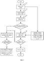
- Insulation diagnosis and defect positioning for the insulated bus pipe are illustrated according to the flowchart described in FIG. 2 , the method provided by the embodiment of the present disclosure includes the steps described below.
- step 210 wirings are connected according to the connection manner shown in FIG. 3 , and a voltage is applied.
- the wirings are connected according to the connection manner shown in FIG. 3 .
- An AC test voltage is applied between a conductor portion of the insulated bus pipe and the ground electrode. If a multi-phrase insulated bus pipe is used, multiple phrases are applied at the same time. The voltage is applied in a frequency series resonance method, or a parallel compensation method or is directly applied.
- an amplitude and frequency of the applied voltage are selected according to the following requirements: a voltage amplitude U t is not lower than 5kV and is not higher than a withstand voltage test level in an equipment status maintenance test; the frequency ranges from 30Hz to 300Hz; a waveform of the test voltage is a sine wave which is approximately symmetrical with respect to positive and negative axes.
- test voltage is adjusted to an appropriate voltage frequency and is gradually boosted to U t . After the voltage is stable, the measurement may be performed and the voltage is kept until the measurement ends.
- step 220 a ground current and test related parameters of each grounded segment are measured.
- Data ( U t , ⁇ ,l , I ) measured in this step is the analyzing basis for the insulation diagnosis and defect positioning of the insulated bus pipe.
- step 230 the ground current values per unit length of different grounded segments are compared.
- the ground currents ( I / l ) per unit length of different grounded segments are compared.
- the ground currents per unit length of different grounded segments are basically equal.
- the insulation status of the insulated bus pipe is abnormal, and a determination method is shown in step 250.
- the same structure includes that the grounded segment has the same quantity of intermediate couplings and the same quantity of insulated bus pipe bodies.
- a measured value of the ground current of the grounded segment is compared with a capacitance current calculation value of this grounded segment.
- the manufacturer experience data includes a capacitance c b per unit length of the body, a capacitance c j per unit length of the intermediate coupling, or ex-factory test data of the capacitance of each intermediate coupling: the capacitances of the intermediate couplings numbered k, k + 1 ... are respectively C jk , C jk+1 , ....
- the measured value of the ground current is compared with the capacitance current value of each grounded segment.
- the measured value of the ground current and the capacitance current value are basically equal for each grounded segment.
- step 250 according to the comparison results of the steps 230 and 240, the insulation status is diagnosed and defects of the insulated bus pipe are positioned.
- ground current values per unit length of different grounded segments are compared. If the ground current values per unit length of the different grounded segments are approximately equal (for example, for each grounded segment, a difference between the ground current per unit length of this grounded segment and the ground current per unit length of each other grounded segment is less than or equal to 10% of the ground current per unit length of this grounded segment), it is considered that the ground current indicator of the of the insulated bus pipe is normal.
- the grounded segment is a defect segment or fault segment.
- the measured value of the ground current of the grounded segment may be compared with the capacitance current calculation value of this grounded segment. If the difference between the measured value of the ground current and the capacitance current calculation value of each grounded segment is very small (for example, the difference between the ground current and the capacitance current value is less than or equal to 3% of the capacitance current value, it is considered that the ground current indicator of the insulated bus pipe is normal.
- the grounded segment is the defect segment or the fault segment.
- the equipment has insulation deterioration, or creeping discharging occurs inside or at an end of the intermediate coupling.
- step 260 the insulation diagnosis and defect positioning end, and test wirings are removed.
Landscapes
- Physics & Mathematics (AREA)
- General Physics & Mathematics (AREA)
- Engineering & Computer Science (AREA)
- Mathematical Physics (AREA)
- Theoretical Computer Science (AREA)
- Chemical & Material Sciences (AREA)
- Ceramic Engineering (AREA)
- Locating Faults (AREA)
- Measurement Of Resistance Or Impedance (AREA)
- Testing Of Short-Circuits, Discontinuities, Leakage, Or Incorrect Line Connections (AREA)
Abstract
Description
- This application is based upon and claims priority to Chinese Patent Application No.
201910662147.X, filed on July 22, 2019 - The present application relates to a technical field of power transmission and distribution, in particular, to an insulation diagnosis and positioning method for an insulated bus pipe.
- The insulated bus pipe is a current-carrying equipment with copper or aluminum metal round tube as a conductor, and has an insulating casing and an outer grounding shield layer. The common voltage level is 6 kV-35 kV, and is mostly used as current-carrying equipment to connect a low-voltage side of the transformer and the switch cabinet. The unique structural characteristic enables the insulated bus pipe to have outstanding advantages of large current-carrying capacity, good mechanical properties, safety, space-saving, small maintenance and good weather resistance. With the development trend of large-capacity, compaction, high safety and high environmental compatibility requirement for power transmission, the insulated bus pipe has been widely used for being suitable for the above development requirements.
- However, unlike semi-insulated buses and closed buses that are previously used in the large-current catchment part, operational reliability of the insulated bus pipe equipment is determined by a solid insulation status of the insulated bus pipe equipment. During the operation, maintenance, and repairing of this type of equipment, an examination and status diagnosis method highly targeted to the common insulation problem of this type of equipment is lacked, so that the equipment is in a uncontrolled state, many defects / hidden dangers could not be detected early, which eventually lead to equipment insulation damage, short-circuit failure, power failure, and serious damage to the equipment such as connected transformers, switch cabinets, causing major losses. Therefore, it is necessary to develop a method for diagnosing the insulation status of this type of equipment.
- The present application provides a rapid insulation diagnosis and defect positioning method which requires less devices, has a high performance on common defects and hidden dangers and is easy to be implemented and executed at maintenance sites. The present application solves the problem of rapid insulation state diagnosis and defect positioning of the equipment by utilizing a structural characteristic of multi-segment connection and segmented grounding of the insulated bus pipe.
- The present application provides an insulation diagnosis and defect positioning method for an insulated bus pipe. The method includes the following steps.
- A first end of an insulated bus pipe is disconnected from other devices and a second end of the insulated bus pipe is disconnected from other devices. Connection between a ground electrode and a line ground wiring of the insulated bus pipe is maintained, and a test voltage is applied between the ground electrode and a conductor portion of the insulated bus pipe.
- The test voltage and a test frequency are recorded when ground currents of grounded segments are measured.
- The multiple grounded segments are identified according to a ground shielded short wiring, and a quantity, a length and a number of intermediate couplings included in each grounded segment are recorded.
- A length of each grounded segment and a ground current of each grounded segment are measured at the test voltage, and a ground current per unit length of each grounded segment is calculated.
- In a case where a consistent test voltage and test frequency are applied to different grounded segments and the different grounded segments have a same structure, ground currents per unit length of the different grounded segments are compared.
- Manufacturer experience data is checked, and the manufacturer experience data includes a capacitance cb per unit length of an insulated bus pipe body, a capacitance cj per unit length of the intermediate couplings or ex-factory test data of the capacitance of each intermediate coupling: capacitances of the intermediate couplings numbered k, k+1,..., k+n comprised in each grounded segment are respectively C jk, C jk+1,... C jk+n. The capacitance current value of each grounded segment is calculated by the following formula: I C=U t /(2πƒ·∑C), where ∑C=c b·l b+c j·l j or ∑C= c b·l b+ C jk+C jk+1+...+ C jk+n, where U t is the test voltage, f is the test frequency, l b is a total length of the insulated bus pipe body comprised in each grounded segment, l j a total length of the intermediate couplings included in each grounded segment, k is a positive integer and n is a non-negative integer. The ground current of each grounded segment is compared with the capacitance current value of each grounded segment.
- The insulation status is diagnosed and defect positioning of the insulated bus pipe is carried out according to a comparison result of the ground currents per unit length of different grounded segments and a comparison result between the ground current of each grounded segment and the capacitance current value of each grounded segment.
- In an embodiment, an amplitude of the test voltage and the test frequency are selected according to the following requirements: a voltage amplitude U t is not lower than 5kV and is not higher than a withstand voltage test level in an insulated bus pipe status maintenance test; the frequency ranges from 30Hz to 300Hz; a waveform is a sine wave which is approximately symmetric with respect to positive and negative axes.
- In an embodiment, applying the test voltage U t between the ground electrode and a conductor portion of the insulated bus pipe includes: applying a voltage with a fixed frequency within the frequency range between the insulated bus pipe and the ground electrode, and boosting the voltage to the test voltage.
- In an embodiment, identifying the grounded segments according to the ground shielded short wiring includes: for the insulated bus pipe whose intermediate coupling is in a shield tube structure, determining a shield tube and the insulated bus pipe body connected by the ground shielded short wiring as one grounded segment; and in a case where no ground shielded short wiring connects the insulated bus pipe body and the shield tube, segmenting the insulated bus pipe body and the shield tube at an intermediate connection position.
- In an embodiment, diagnosing the insulation status and implementing defect positioning of the insulated bus pipe according to the comparison result of the ground currents per unit length of different grounded segments and the comparison result between the ground current of each grounded segment and the capacitance current value of each grounded segment includes the following steps.
- In a case where for each grounded segment, a difference between the ground current per unit length of the grounded segment and the ground current per unit length of each other grounded segment is less than or equal to 10% of the ground current per unit length of the grounded segment, it is determined that a ground current indicator of the insulated bus pipe is normal. In a case where the difference between the ground current per unit length of one grounded segment and the ground current per unit length of each other grounded segment is greater than 10% of the ground current per unit length of the one grounded segment, it is determined that the one grounded segment is a defect segment or a fault segment.
- In a case where for each grounded segment, a difference between the ground current and the capacitance current value is less than or equal to 3% of the capacitance current value, it is determined that a current indicator of the insulated bus pipe is normal. In a case where a difference between the ground current of one grounded segment and the capacitance current value of the one grounded segment is greater than 3%, it is determined that the one grounded segment is the defect segment or the fault segment.
- In a case where a ground current value of the defect segment or the fault segment is greater than a preset value, it is determined that the insulated bus pipe insulation has insulation deterioration, or creeping discharging occurs in an interior or an end part of the intermediate coupling of the defect segment or the fault segment.
- The embodiment of the present disclosure further provides an electronic device. The electronic device includes a processor and a memory. The memory is configured to store computer programs which, when executed by the processor, implement the method provided by any embodiment described above.
- An embodiment of the present application provides a computer-readable storage medium. The computer-readable storage medium is configured to store computer programs which, when executed by a processor, implement the method provided by any embodiment described above.
-
-
FIG. 1 is a flowchart of an insulation diagnosis and defect positioning method for an insulated bus pipe provided by an embodiment of the present disclosure; -
FIG. 2 is a flowchart of another insulation diagnosis and defect positioning method for an insulated bus pipe provided by an embodiment of the present disclosure; -
FIG. 3 is a schematic diagram of a testing circuitry for boosting multiple segments of an insulated bus pipe and performing ground current measurement provided by an embodiment of the present disclosure; and -
FIG. 4 is a schematic diagram of a method for identifying a structure and segmenting manner of multiple segments of an insulated bus pipe provided by an embodiment of the present disclosure. - Technical solutions of the present disclosure will be described below with reference to the drawings.
- The insulated bus pipe equipment includes multiple segments which are integrated into a whole, and is grounding in segments, such grounding manner is complex, but provides convenience for insulation status detection and fault positioning of this type of equipment. Therefore, the present disclosure provides an insulation diagnosis and defect positioning method based on the ground current measurement.
-
FIG. 1 is a flowchart of an insulation diagnosis and defect positioning method for an insulated bus pipe provided by an embodiment of the present disclosure. Referring toFIG. 1 , the method provided by the present disclosure includes the steps described below. - In
step 110, a first end of an insulated bus pipe is disconnected from other equipment and a second end of the insulated bus pipe is disconnected from other equipment, a connection between a ground electrode and a line ground wiring of the insulated bus pipe is kept, and a test voltage is applied between the ground electrode and a conductor portion of the insulated bus pipe. - In step 120: the test voltage and a test frequency is recorded during the measurement of ground currents of grounded segments.
- In
step 130, the multiple grounded segments are identified according to a ground shielded short wiring, and a quantity, a length and a number of intermediate couplings included in each grounded segment are recorded. - In
step 140, a length of each grounded segment is measured. - In
step 150, a ground current of each grounded segment is measured at the test voltage, and a ground current per unit length of each grounded segment is calculated. - In
step 160, in a case where a consistent test voltage and test frequency are applied to different grounded segments and the different grounded segments have a same structure, the ground currents per unit length of different grounded segments are compared. - In
step 170, manufacturer experience data is checked, the manufacturer experience data includes a capacitance cb per unit length of an insulated bus pipe body, a capacitance cj per unit length of the intermediate coupling or ex-factory test data of the capacitance of each intermediate coupling: capacitances of the intermediate couplings numbered k, k+1, ..., k+n included in each insulated bus pipe grounded section are respectively C jk, C jk+1, ... C jk+n; a capacitance current value of each insulated bus pipe grounded section is calculated by the following formula: Ic=Ut /(2πƒ·∑C), where ∑C=c b·l b+c j·l j or ∑C= c b·l b+ C jk+Cjk+1+...+ C jk+n, where U t is the test voltage, f is the test frequency, l b is a total length of the insulated bus pipe bodies of the ground sections, l j a total length of the intermediate couplings included in the insulated bus pipe grounded sections, k is a positive integer and n is a non-negative integer. The ground current of each insulated bus pipe grounded section is compared with the capacitance current value of each insulated bus pipe grounded section. - In
step 180, an insulation status is diagnosed and defect positioning of the insulated bus pipe is implemented according to a comparison result of the ground currents per unit length of different grounded segments and a comparison result between the ground current of each grounded segment and the capacitance current value of each grounded segment. - Insulation diagnosis and defect positioning for the insulated bus pipe are illustrated according to the flowchart described in
FIG. 2 , the method provided by the embodiment of the present disclosure includes the steps described below. - In
step 210, wirings are connected according to the connection manner shown inFIG. 3 , and a voltage is applied. - After disconnecting the two ends of the insulated bus pipe from other equipment (such as a transformer, a switch cabinet, etc.), the wirings are connected according to the connection manner shown in
FIG. 3 . An AC test voltage is applied between a conductor portion of the insulated bus pipe and the ground electrode. If a multi-phrase insulated bus pipe is used, multiple phrases are applied at the same time. The voltage is applied in a frequency series resonance method, or a parallel compensation method or is directly applied. In an embodiment, an amplitude and frequency of the applied voltage are selected according to the following requirements: a voltage amplitude U t is not lower than 5kV and is not higher than a withstand voltage test level in an equipment status maintenance test; the frequency ranges from 30Hz to 300Hz; a waveform of the test voltage is a sine wave which is approximately symmetrical with respect to positive and negative axes. - After wiring connection is completed, the test voltage is adjusted to an appropriate voltage frequency and is gradually boosted to U t. After the voltage is stable, the measurement may be performed and the voltage is kept until the measurement ends.
- In
step 220, a ground current and test related parameters of each grounded segment are measured. - (1) The test voltage U t and a frequency f at the time of measuring a ground current of each of the grounded segments are recorded.
- (2) The grounded segments are identified according to the ground shielded short wiring shown in
FIG. 4 . For the insulated bus pipe whose intermediate coupling is in a shield tube structure, the shield tube and the body connected by the ground shielded short wiring serve as one grounded segment. If no ground shielded short wiring apparently connects the body and the shield tube, the wiring is segmented at an intermediate connection. - (3) The quantity, length and number of intermediate couplings included in each grounded segment are recorded.
- (4) A length / of each grounded segment is measured.
- (5) A ground current I of each grounded segment at the test voltage is measured.
- Data (Ut,ƒ,l,I) measured in this step is the analyzing basis for the insulation diagnosis and defect positioning of the insulated bus pipe.
- In
step 230, the ground current values per unit length of different grounded segments are compared. - When different grounded segments have a consistent applied voltage (an amplitude U t and a frequency ƒ) and a same structure (same quantity of intermediate couplings and same intermediate coupling type), the ground currents (I/l) per unit length of different grounded segments are compared. The ground currents per unit length of different grounded segments are basically equal. When the ground currents have a large difference, the insulation status of the insulated bus pipe is abnormal, and a determination method is shown in step 250.
- In an embodiment, the same structure includes that the grounded segment has the same quantity of intermediate couplings and the same quantity of insulated bus pipe bodies. In
step 240, a measured value of the ground current of the grounded segment is compared with a capacitance current calculation value of this grounded segment. - According to the test voltage U t , the test frequency f, the length l b of the insulated bus pipe body included in a certain grounded segment, and numbers k, k+1 ... or length l j of the intermediate coupling, manufacturer experience data is checked. The manufacturer experience data includes a capacitance c b per unit length of the body, a capacitance c j per unit length of the intermediate coupling, or ex-factory test data of the capacitance of each intermediate coupling: the capacitances of the intermediate couplings numbered k, k+1... are respectively C jk, C jk+1, .... The capacitance current value of the grounded segment is calculated: Ic=Ut /(2πf•ΣC), where ∑C=cb•l b+c j•lj or ∑C= c b•l b+ C jk+Cjk+1+....
- After calculating the capacitance current value of each grounded segment, the measured value of the ground current is compared with the capacitance current value of each grounded segment. The measured value of the ground current and the capacitance current value are basically equal for each grounded segment. When the measured value of the ground current and the capacitance current value have a large difference, the insulation status of the insulated bus pipe is abnormal, and a determination method is shown in the step 250.
- In step 250, according to the comparison results of the
steps - The ground current values per unit length of different grounded segments are compared. If the ground current values per unit length of the different grounded segments are approximately equal (for example, for each grounded segment, a difference between the ground current per unit length of this grounded segment and the ground current per unit length of each other grounded segment is less than or equal to 10% of the ground current per unit length of this grounded segment), it is considered that the ground current indicator of the of the insulated bus pipe is normal. If the difference between the ground current value per unit length of a certain grounded segment and the ground current value per unit length of other grounded segment is large (for example, the difference between the ground current value per unit length of a certain grounded segment and the ground current value per unit length of other grounded segment is greater than 10% of the ground current per unit length of this grounded segment), it is considered that the grounded segment is a defect segment or fault segment.
- For the insulated bus pipe with complete manufacturer information, when the insulation status of the equipment needs to be determined more accurately, the measured value of the ground current of the grounded segment may be compared with the capacitance current calculation value of this grounded segment. If the difference between the measured value of the ground current and the capacitance current calculation value of each grounded segment is very small (for example, the difference between the ground current and the capacitance current value is less than or equal to 3% of the capacitance current value, it is considered that the ground current indicator of the insulated bus pipe is normal. If the difference between the measured value of the ground current and the capacitance current calculation value of this grounded segment is relatively larger (for example, the difference between the ground current and the capacitance current value is greater than 3% of the capacitance current value), the grounded segment is the defect segment or the fault segment.
- In the above comparison, if the measured value of the ground current in the defect segment or the fault segment is too large, such as greater than a preset value, the equipment has insulation deterioration, or creeping discharging occurs inside or at an end of the intermediate coupling.
- In step 260, the insulation diagnosis and defect positioning end, and test wirings are removed.
- In a simulation test carried out to verify rationality and effectiveness of this method, simulation of applying a voltage to 3 segments of insulated bus pipe specified by 10kV / 2500A produced by a certain factory is carried out. The length of each segment is 2.1 m, and the first segment is a sample in good insulation status, the second segment is a sample for simulating a capacitance shielding caused by internal defects, and the third segment is a sample for simulating dirty insulation (relatively severe) and being watered at the external end. An AC voltage with an amplitude of 10 kV and a frequency of 50 Hz is applied according to the manner shown in
FIG. 3 . Ground currents of three grounded segments are measured to be 5.54 mA, 7.21 mA and 8.58 mA. The following may be obtained by analysis. - (1) Ground current values per unit length of three grounded segments are 2.64 mA/m, 3.43 mA/m and 4.10 mA/m, the ground current value per unit length of the second grounded segment is larger than that of the first segment by 30%, and the ground current value per unit length of the third grounded segment is larger than that of the first segment by 55%. It is shown that the comparison determination method of the
step 230 is effective. - (2) The three grounded segments have the same capacitance current calculation value (the structure and material are same), which is 5.50mA. The ground current value of the first insulated bus pipe segment is larger than the capacitance current calculation value of the first insulated bus pipe segment by 1%. The ground current value of the second insulated bus pipe segment is larger than the capacitance current calculation value of the second insulated bus pipe segment by 31%. The ground current value of the third insulated bus pipe segment is larger than the capacitance current calculation value of the third insulated bus pipe segment by 56%. It is shown that the comparison determination method of the
step 240 is effective. - When insulated bus pipes of the same structure and network operation are in good insulation status, the power is cut off to perform the measurement provided in this application. When a 10 kV voltage is applied, the ground currents per unit length of multiple grounded segments are close to 2.63mA/m, the delta among the ground currents per unit length of different segments is not great than 10%. It is further shown that the determination manner described in this application is effective.
Claims (7)
- An insulation diagnosis and defect positioning method for an insulated bus pipe, comprising:disconnecting a first end of the insulated bus pipe from other equipment and a second end of the insulated bus pipe from other equipment, keeping connection between a ground electrode and a line ground wiring of the insulated bus pipe and applying a test voltage between the ground electrode and a conductor portion of the insulated bus pipe;recording the test voltage and a test frequency when measuring a ground current of each of a plurality of grounded segments of the insulated bus pipe;identifying the plurality of grounded segments according to a ground shielded short wiring, and recording a quantity, a number and a length of intermediate couplings comprised in each grounded segment;measuring a length of each grounded segment and a ground current of each grounded segment at the test voltage, and calculating a ground current per unit length of each grounded segment;in a case where a consistent test voltage is applied to different grounded segments with a consistent test frequency and the different grounded segments have a same structure, comparing the ground currents per unit length of different grounded segments;checking manufacturer experience data, where the manufacturer experience data comprises a capacitance c b per unit length of an insulated bus pipe body, a capacitance c j per unit length of the intermediate coupling or ex-factory test data of the capacitance of each intermediate coupling: capacitances of the intermediate couplings numbered k, k+1,...,k+n comprised in each grounded segment are respectively C jk, C jk+1, ... C jk+n; calculating a capacitance current value of each grounded segment by the following formula: I C=U t /(2πƒ·∑C), where ∑C=c b·l b+cj·lj or ΣC= c b·l b+C jk+C jk+1+...+ C jk+n, wherein U t is the test voltage, f is the test frequency, l b is a total length of the insulated bus pipe body comprised in each grounded segment, l j a total length of the intermediate couplings comprised in the plurality of grounded segments, k is a positive integer and n is a non-negative integer; and comparing the ground current of each grounded segment with the capacitance current value of each grounded segment; anddiagnosing an insulation status and implementing defect positioning of the insulated bus pipe according to the comparing result of the ground currents per unit length of different grounded segments and the comparing result between the ground current of each grounded segment and the capacitance current value of each grounded segment.
- The method of claim 1, wherein an amplitude of the test voltage and the test frequency are selected from: a voltage amplitude U t is not lower than 5kV and is not higher than a withstand voltage test level in an insulated bus pipe status maintenance test; the frequency ranges from 30Hz to 300Hz; and a waveform of the test voltage is a sine wave which is approximately symmetric with respect to positive and negative axes.
- The method of claim 2, wherein applying the test voltage between the ground electrode and the insulated bus pipe comprises: applying a voltage with a fixed frequency within the frequency range between the conductor portion of the insulated bus pipe and the ground electrode, and boosting the voltage to the test voltage.
- The method of claim 1, wherein identifying the grounded segments according to the ground shielding short wiring comprises: for the insulated bus pipe whose intermediate coupling is in a shield tube structure, determining a shield tube and the insulated bus pipe body connected by the ground shielded short wiring as one grounded segment; and in a case where no ground shielded short wiring connects the insulated bus pipe body and the shield tube, segmenting the insulated bus pipe body and the shield tube at an intermediate connection position.
- The method of claim 1, wherein diagnosing the insulation status and implementing the defect positioning of the insulated bus pipe according to the comparison result of the ground currents per unit length of different grounded segments and the comparison result between the ground current of each grounded segment and the capacitance current value of each grounded segment comprises:in a case where for each grounded segment, a difference between the ground current per unit length of the grounded segment and the ground current per unit length of each other grounded segment is less than or equal to 10% of the ground current per unit length of the grounded segment, determining that a ground current indicator of the insulated bus pipe is normal; in a case where the difference between the ground current per unit length of one grounded segment and the ground current per unit length of each other grounded segment is greater than 10% of the ground current per unit length of the one grounded segment, determining that the one grounded segment is a defect segment or a fault segment;in a case where for each grounded segment, a difference between the ground current and the capacitance current value is less than or equal to 3% of the capacitance current value, determining that a current indicator of the insulated bus pipe is normal; in a case where a difference between the ground current of one grounded segment and the capacitance current value of the one grounded segment is greater than 3%, confirming that the one grounded segment is the defect segment or the fault segment; andin a case where a ground current value of the defect segment or the fault segment is greater than a preset value, determining that the insulated bus pipe insulation has insulation deterioration, or creeping discharging occurs in an interior or an end part of the intermediate coupling of the defect segment or the fault segment.
- An electronic device, comprising a processor and a memory, wherein the memory is configured to store computer programs which, when executed by the processor, implement the method of any one of claims 1 to 5.
- A computer-readable storage medium, which is configured to store computer programs which, when executed by the processor, implement the method of any one of claims 1 to 5.
Applications Claiming Priority (2)
| Application Number | Priority Date | Filing Date | Title |
|---|---|---|---|
| CN201910662147.XA CN110412418B (en) | 2019-07-22 | 2019-07-22 | Insulation tubular bus insulation diagnosis and positioning method based on grounding current measurement |
| PCT/CN2020/070476 WO2021012639A1 (en) | 2019-07-22 | 2020-01-06 | Insulation diagnosis and positioning method for insulated tube-type bus bar |
Publications (4)
| Publication Number | Publication Date |
|---|---|
| EP3798650A1 true EP3798650A1 (en) | 2021-03-31 |
| EP3798650A4 EP3798650A4 (en) | 2022-03-30 |
| EP3798650B1 EP3798650B1 (en) | 2024-08-07 |
| EP3798650C0 EP3798650C0 (en) | 2024-08-07 |
Family
ID=68362386
Family Applications (1)
| Application Number | Title | Priority Date | Filing Date |
|---|---|---|---|
| EP20711768.0A Active EP3798650B1 (en) | 2019-07-22 | 2020-01-06 | Insulation diagnosis and locating method for insulated tube-type bus bar |
Country Status (4)
| Country | Link |
|---|---|
| US (1) | US10948532B1 (en) |
| EP (1) | EP3798650B1 (en) |
| CN (1) | CN110412418B (en) |
| WO (1) | WO2021012639A1 (en) |
Families Citing this family (5)
| Publication number | Priority date | Publication date | Assignee | Title |
|---|---|---|---|---|
| EP3675302B1 (en) * | 2018-12-27 | 2021-04-14 | Vito NV | A method and device for monitoring insulation between a dc bus and protective earth |
| CN110412418B (en) * | 2019-07-22 | 2020-07-31 | 国网湖北省电力有限公司电力科学研究院 | Insulation tubular bus insulation diagnosis and positioning method based on grounding current measurement |
| CN114089126A (en) * | 2021-09-28 | 2022-02-25 | 国网浙江省电力有限公司绍兴供电公司 | Soil breakdown field strength test device for safety evaluation of buried pipeline below power grid |
| CN115856406B (en) * | 2022-06-22 | 2026-01-13 | 国网湖南省电力有限公司 | Intelligent control method and system for substation bus capacitor current |
| CN115754517B (en) * | 2022-10-31 | 2025-09-02 | 中国电力工程顾问集团西南电力设计院有限公司 | A remote monitoring system for the status of a self-limiting temperature heating belt |
Family Cites Families (33)
| Publication number | Priority date | Publication date | Assignee | Title |
|---|---|---|---|---|
| US6300767B1 (en) * | 1998-11-30 | 2001-10-09 | General Electric Company | System and apparatus for predicting failure in insulated systems |
| CN1702780A (en) * | 2005-06-13 | 2005-11-30 | 罗志昭 | Novel insulated main lead |
| JP4504904B2 (en) * | 2005-10-31 | 2010-07-14 | アスモ株式会社 | Code switch and detection device using the same |
| CN201229389Y (en) * | 2008-07-24 | 2009-04-29 | 福建省泉州电业局 | Cable sheath insulation on-line monitoring device |
| JP5380702B2 (en) * | 2008-11-28 | 2014-01-08 | 株式会社三和技術総合研究所 | Leakage current measuring device and measuring method |
| CN101793936A (en) * | 2010-02-11 | 2010-08-04 | 河南省电力公司商丘供电公司 | Insulation state online monitoring method for condenser type bushings |
| BR112013024503A2 (en) * | 2011-03-25 | 2017-08-08 | Eandis | high voltage measurement systems |
| CN102680854B (en) * | 2012-05-08 | 2014-08-20 | 山东康威通信技术股份有限公司 | Online monitoring method for covert faults and joint process defects of power cable |
| CN202661585U (en) * | 2012-05-09 | 2013-01-09 | 广东电网公司佛山供电局 | Insulation state test system for insulation copper tube bus-bar |
| CN103217613B (en) * | 2013-03-23 | 2015-07-08 | 李景禄 | Power transmission and distribution line fault property judgment and fault state tracing and detecting method |
| EP2796886B1 (en) * | 2013-04-23 | 2017-09-06 | Technische Universität Graz | Circuit assembly for locating of insulation faults |
| CN103592563A (en) * | 2013-11-22 | 2014-02-19 | 国家电网公司 | Direct current system insulation on-line monitoring device |
| FR3015040B1 (en) * | 2013-12-16 | 2016-01-08 | Continental Automotive France | DEVICE FOR CONTINUOUSLY DETECTING ELECTRIC ISOLATION BREAKAGE OF A HIGH VOLTAGE CABLE AND DETECTION METHOD THEREOF |
| TWI539169B (en) * | 2014-04-08 | 2016-06-21 | Univ Kao Yuan | High Sensitivity Non - grounded DC Power Supply Insulation Resistance Detection Method and Its Circuit |
| JP6433305B2 (en) * | 2014-04-09 | 2018-12-05 | 矢崎総業株式会社 | Insulation detection device and insulation detection method for non-grounded power supply |
| CN104483571B (en) * | 2014-12-17 | 2017-11-10 | 安徽泰瑞通达机电设备有限公司 | Cable insulation detection method |
| CN104535894B (en) * | 2015-01-08 | 2017-07-07 | 国家电网公司 | Earth fault line selection method and device under the double-bus method of operation |
| CN204855722U (en) * | 2015-07-27 | 2015-12-09 | 国网天津市电力公司 | Insulating tubular busbar partial discharge detector system of 10kV |
| CN205120882U (en) * | 2015-08-28 | 2016-03-30 | 西安神电高压电器有限公司 | Tubular busbar monitoring devices |
| CN205157649U (en) * | 2015-10-27 | 2016-04-13 | 镇江华东电力设备制造厂有限公司 | Monitoring system for seal on insulating tubular busbar |
| KR102544778B1 (en) * | 2016-06-16 | 2023-06-19 | 삼성전자주식회사 | Method for detecting leakage current and electronic device supporting the same |
| CN106249112A (en) * | 2016-08-04 | 2016-12-21 | 国网天津市电力公司 | 10kV insulating tube type busbar transition joint partial discharge detecting system |
| CN206533138U (en) * | 2017-03-10 | 2017-09-29 | 湖北三宁化工股份有限公司 | A kind of device of limitation 10kV distribution system capacitive earth currents |
| CN107121623A (en) * | 2017-04-19 | 2017-09-01 | 天津市电力科技发展有限公司 | A kind of insulating tube type busbar partial discharge monitoring system |
| CN207301251U (en) * | 2017-10-19 | 2018-05-01 | 桂林师范高等专科学校 | Transformer insulated property detection device |
| CN108152662A (en) * | 2017-11-24 | 2018-06-12 | 国网浙江省电力公司台州供电公司 | A kind of cross interconnected box fault diagnosis method and system based on earth current |
| CN108594097A (en) * | 2018-05-02 | 2018-09-28 | 国网福建省电力有限公司莆田供电公司 | A method of medium and high voltage cable state of insulation is judged by protective metal shell circulation |
| CN109444644B (en) * | 2018-12-21 | 2020-12-29 | 南京国电南自电网自动化有限公司 | Transient component differential-based power distribution network single-phase earth fault line selection method |
| CN109633357B (en) * | 2019-01-10 | 2021-06-18 | 许继电源有限公司 | Monitoring method and monitoring device for grounding insulation of multiple busbars among three busbars |
| CN109884467B (en) * | 2019-03-04 | 2020-06-02 | 国网湖北省电力有限公司电力科学研究院 | A device and method for locating insulation faults of insulated tubular busbars |
| CN109738770A (en) * | 2019-03-05 | 2019-05-10 | 四川艾德瑞电气有限公司 | An integrated monitoring system for insulated tubular busbar connectors |
| CN109917230B (en) * | 2019-04-08 | 2020-09-01 | 重庆大学 | Integrated method of ground fault monitoring and protection for distribution network with neutral point grounded with resistance |
| CN110412418B (en) * | 2019-07-22 | 2020-07-31 | 国网湖北省电力有限公司电力科学研究院 | Insulation tubular bus insulation diagnosis and positioning method based on grounding current measurement |
-
2019
- 2019-07-22 CN CN201910662147.XA patent/CN110412418B/en active Active
-
2020
- 2020-01-06 EP EP20711768.0A patent/EP3798650B1/en active Active
- 2020-01-06 WO PCT/CN2020/070476 patent/WO2021012639A1/en not_active Ceased
- 2020-01-06 US US16/648,114 patent/US10948532B1/en not_active Expired - Fee Related
Also Published As
| Publication number | Publication date |
|---|---|
| WO2021012639A1 (en) | 2021-01-28 |
| CN110412418A (en) | 2019-11-05 |
| EP3798650B1 (en) | 2024-08-07 |
| US20210055339A1 (en) | 2021-02-25 |
| EP3798650C0 (en) | 2024-08-07 |
| CN110412418B (en) | 2020-07-31 |
| US10948532B1 (en) | 2021-03-16 |
| EP3798650A4 (en) | 2022-03-30 |
Similar Documents
| Publication | Publication Date | Title |
|---|---|---|
| US10948532B1 (en) | Insulation diagnosis and positioning method for insulated bus pipe | |
| CN103091609B (en) | A kind of GIS local discharge on-line monitoring device performance detecting system and method thereof | |
| CN102735959A (en) | On-line ultrahigh-voltage line power transformer test method | |
| CN114217166A (en) | FDR frequency domain waveform-based transformer substation low-voltage cable local defect positioning method | |
| CN205992025U (en) | A kind of 220KV and above capacitance type potential transformer test circuit | |
| CN108594097A (en) | A method of medium and high voltage cable state of insulation is judged by protective metal shell circulation | |
| CN117554856B (en) | Performance verification device and method for active defense equipment for turn-to-turn short circuit of transformer | |
| Ushakov et al. | Transformer Condition Control | |
| CN205429680U (en) | Cable cross -bonding case | |
| CN107817430A (en) | A kind of method that cable local discharge defect is observed by transparent terminal | |
| CN114113944B (en) | A CVT capacitor unit breakdown defect testing method and device | |
| Ushakov et al. | Diagnostics of High-Voltage Cable Lines | |
| CN107024613A (en) | High-voltage feedback power cable square wave on-line overvoltage monitor | |
| Guastavino et al. | Transient Earth Voltage Sensor Measurements as a Nonintrusive Tool for Partial Discharge Analysis in Switchgears | |
| Arunachalam et al. | Extended application for the impulse-based frequency response analysis: Preliminary diagnosis of partial discharges in transformer | |
| CN207832951U (en) | A kind of capacitance type potential transformer insulation line monitoring device | |
| CN107917661B (en) | Function inspection device for frequency response type winding deformation tester | |
| JPH07294588A (en) | Identification method under live line of cable insulation defective section | |
| CN205958708U (en) | Alternate water -cooled generator direct current test instrument that has water path connection | |
| CN116449162A (en) | Simulation test device and monitoring method for turn-to-turn discharge defects of large power transformer | |
| Rao et al. | An improved method for identification of mechanical damage in an isolated transformer winding using FRA | |
| CN110632481B (en) | Medium-voltage cable body insulation defect degree identification method | |
| CN203535206U (en) | GIS partial discharging simulation system | |
| Alawady et al. | Short-circuit Fault Detection in Power Transformer Using Frequency Response Analysis bipolar signature of Inductive Inter-Winding Measurement | |
| Nasirpour et al. | Evaluation of online techniques utilized for extracting the transformer transfer function |
Legal Events
| Date | Code | Title | Description |
|---|---|---|---|
| STAA | Information on the status of an ep patent application or granted ep patent |
Free format text: STATUS: UNKNOWN |
|
| STAA | Information on the status of an ep patent application or granted ep patent |
Free format text: STATUS: THE INTERNATIONAL PUBLICATION HAS BEEN MADE |
|
| PUAI | Public reference made under article 153(3) epc to a published international application that has entered the european phase |
Free format text: ORIGINAL CODE: 0009012 |
|
| STAA | Information on the status of an ep patent application or granted ep patent |
Free format text: STATUS: REQUEST FOR EXAMINATION WAS MADE |
|
| 17P | Request for examination filed |
Effective date: 20200326 |
|
| AK | Designated contracting states |
Kind code of ref document: A1 Designated state(s): AL AT BE BG CH CY CZ DE DK EE ES FI FR GB GR HR HU IE IS IT LI LT LU LV MC MK MT NL NO PL PT RO RS SE SI SK SM TR |
|
| AX | Request for extension of the european patent |
Extension state: BA ME |
|
| A4 | Supplementary search report drawn up and despatched |
Effective date: 20220302 |
|
| RIC1 | Information provided on ipc code assigned before grant |
Ipc: H02G 5/06 20060101ALI20220224BHEP Ipc: H01R 4/64 20060101ALI20220224BHEP Ipc: G01R 31/12 20200101ALI20220224BHEP Ipc: G01R 31/00 20060101ALI20220224BHEP Ipc: G01R 31/08 20200101AFI20220224BHEP |
|
| DAV | Request for validation of the european patent (deleted) | ||
| DAX | Request for extension of the european patent (deleted) | ||
| GRAP | Despatch of communication of intention to grant a patent |
Free format text: ORIGINAL CODE: EPIDOSNIGR1 |
|
| STAA | Information on the status of an ep patent application or granted ep patent |
Free format text: STATUS: GRANT OF PATENT IS INTENDED |
|
| INTG | Intention to grant announced |
Effective date: 20240314 |
|
| GRAS | Grant fee paid |
Free format text: ORIGINAL CODE: EPIDOSNIGR3 |
|
| GRAA | (expected) grant |
Free format text: ORIGINAL CODE: 0009210 |
|
| STAA | Information on the status of an ep patent application or granted ep patent |
Free format text: STATUS: THE PATENT HAS BEEN GRANTED |
|
| AK | Designated contracting states |
Kind code of ref document: B1 Designated state(s): AL AT BE BG CH CY CZ DE DK EE ES FI FR GB GR HR HU IE IS IT LI LT LU LV MC MK MT NL NO PL PT RO RS SE SI SK SM TR |
|
| REG | Reference to a national code |
Ref country code: GB Ref legal event code: FG4D |
|
| REG | Reference to a national code |
Ref country code: CH Ref legal event code: EP |
|
| REG | Reference to a national code |
Ref country code: IE Ref legal event code: FG4D |
|
| REG | Reference to a national code |
Ref country code: DE Ref legal event code: R096 Ref document number: 602020035271 Country of ref document: DE |
|
| U01 | Request for unitary effect filed |
Effective date: 20240906 |
|
| U07 | Unitary effect registered |
Designated state(s): AT BE BG DE DK EE FI FR IT LT LU LV MT NL PT RO SE SI Effective date: 20240920 |
|
| PG25 | Lapsed in a contracting state [announced via postgrant information from national office to epo] |
Ref country code: NO Free format text: LAPSE BECAUSE OF FAILURE TO SUBMIT A TRANSLATION OF THE DESCRIPTION OR TO PAY THE FEE WITHIN THE PRESCRIBED TIME-LIMIT Effective date: 20241107 |
|
| PG25 | Lapsed in a contracting state [announced via postgrant information from national office to epo] |
Ref country code: PL Free format text: LAPSE BECAUSE OF FAILURE TO SUBMIT A TRANSLATION OF THE DESCRIPTION OR TO PAY THE FEE WITHIN THE PRESCRIBED TIME-LIMIT Effective date: 20240807 Ref country code: GR Free format text: LAPSE BECAUSE OF FAILURE TO SUBMIT A TRANSLATION OF THE DESCRIPTION OR TO PAY THE FEE WITHIN THE PRESCRIBED TIME-LIMIT Effective date: 20241108 |
|
| PG25 | Lapsed in a contracting state [announced via postgrant information from national office to epo] |
Ref country code: IS Free format text: LAPSE BECAUSE OF FAILURE TO SUBMIT A TRANSLATION OF THE DESCRIPTION OR TO PAY THE FEE WITHIN THE PRESCRIBED TIME-LIMIT Effective date: 20241207 |
|
| PG25 | Lapsed in a contracting state [announced via postgrant information from national office to epo] |
Ref country code: HR Free format text: LAPSE BECAUSE OF FAILURE TO SUBMIT A TRANSLATION OF THE DESCRIPTION OR TO PAY THE FEE WITHIN THE PRESCRIBED TIME-LIMIT Effective date: 20240807 |
|
| PG25 | Lapsed in a contracting state [announced via postgrant information from national office to epo] |
Ref country code: ES Free format text: LAPSE BECAUSE OF FAILURE TO SUBMIT A TRANSLATION OF THE DESCRIPTION OR TO PAY THE FEE WITHIN THE PRESCRIBED TIME-LIMIT Effective date: 20240807 Ref country code: RS Free format text: LAPSE BECAUSE OF FAILURE TO SUBMIT A TRANSLATION OF THE DESCRIPTION OR TO PAY THE FEE WITHIN THE PRESCRIBED TIME-LIMIT Effective date: 20241107 |
|
| PG25 | Lapsed in a contracting state [announced via postgrant information from national office to epo] |
Ref country code: RS Free format text: LAPSE BECAUSE OF FAILURE TO SUBMIT A TRANSLATION OF THE DESCRIPTION OR TO PAY THE FEE WITHIN THE PRESCRIBED TIME-LIMIT Effective date: 20241107 Ref country code: PL Free format text: LAPSE BECAUSE OF FAILURE TO SUBMIT A TRANSLATION OF THE DESCRIPTION OR TO PAY THE FEE WITHIN THE PRESCRIBED TIME-LIMIT Effective date: 20240807 Ref country code: NO Free format text: LAPSE BECAUSE OF FAILURE TO SUBMIT A TRANSLATION OF THE DESCRIPTION OR TO PAY THE FEE WITHIN THE PRESCRIBED TIME-LIMIT Effective date: 20241107 Ref country code: IS Free format text: LAPSE BECAUSE OF FAILURE TO SUBMIT A TRANSLATION OF THE DESCRIPTION OR TO PAY THE FEE WITHIN THE PRESCRIBED TIME-LIMIT Effective date: 20241207 Ref country code: HR Free format text: LAPSE BECAUSE OF FAILURE TO SUBMIT A TRANSLATION OF THE DESCRIPTION OR TO PAY THE FEE WITHIN THE PRESCRIBED TIME-LIMIT Effective date: 20240807 Ref country code: GR Free format text: LAPSE BECAUSE OF FAILURE TO SUBMIT A TRANSLATION OF THE DESCRIPTION OR TO PAY THE FEE WITHIN THE PRESCRIBED TIME-LIMIT Effective date: 20241108 Ref country code: ES Free format text: LAPSE BECAUSE OF FAILURE TO SUBMIT A TRANSLATION OF THE DESCRIPTION OR TO PAY THE FEE WITHIN THE PRESCRIBED TIME-LIMIT Effective date: 20240807 |
|
| U20 | Renewal fee for the european patent with unitary effect paid |
Year of fee payment: 6 Effective date: 20250124 |
|
| PG25 | Lapsed in a contracting state [announced via postgrant information from national office to epo] |
Ref country code: SM Free format text: LAPSE BECAUSE OF FAILURE TO SUBMIT A TRANSLATION OF THE DESCRIPTION OR TO PAY THE FEE WITHIN THE PRESCRIBED TIME-LIMIT Effective date: 20240807 |
|
| PG25 | Lapsed in a contracting state [announced via postgrant information from national office to epo] |
Ref country code: CZ Free format text: LAPSE BECAUSE OF FAILURE TO SUBMIT A TRANSLATION OF THE DESCRIPTION OR TO PAY THE FEE WITHIN THE PRESCRIBED TIME-LIMIT Effective date: 20240807 |
|
| PG25 | Lapsed in a contracting state [announced via postgrant information from national office to epo] |
Ref country code: SK Free format text: LAPSE BECAUSE OF FAILURE TO SUBMIT A TRANSLATION OF THE DESCRIPTION OR TO PAY THE FEE WITHIN THE PRESCRIBED TIME-LIMIT Effective date: 20240807 |
|
| PLBE | No opposition filed within time limit |
Free format text: ORIGINAL CODE: 0009261 |
|
| STAA | Information on the status of an ep patent application or granted ep patent |
Free format text: STATUS: NO OPPOSITION FILED WITHIN TIME LIMIT |
|
| 26N | No opposition filed |
Effective date: 20250508 |
|
| REG | Reference to a national code |
Ref country code: CH Ref legal event code: PL |
|
| PG25 | Lapsed in a contracting state [announced via postgrant information from national office to epo] |
Ref country code: MC Free format text: LAPSE BECAUSE OF FAILURE TO SUBMIT A TRANSLATION OF THE DESCRIPTION OR TO PAY THE FEE WITHIN THE PRESCRIBED TIME-LIMIT Effective date: 20240807 |
|
| GBPC | Gb: european patent ceased through non-payment of renewal fee |
Effective date: 20250106 |
|
| PG25 | Lapsed in a contracting state [announced via postgrant information from national office to epo] |
Ref country code: GB Free format text: LAPSE BECAUSE OF NON-PAYMENT OF DUE FEES Effective date: 20250106 |
|
| PG25 | Lapsed in a contracting state [announced via postgrant information from national office to epo] |
Ref country code: CH Free format text: LAPSE BECAUSE OF NON-PAYMENT OF DUE FEES Effective date: 20250131 |
|
| PG25 | Lapsed in a contracting state [announced via postgrant information from national office to epo] |
Ref country code: IE Free format text: LAPSE BECAUSE OF NON-PAYMENT OF DUE FEES Effective date: 20250106 |
|
| U20 | Renewal fee for the european patent with unitary effect paid |
Year of fee payment: 7 Effective date: 20260119 |