EP3798613A1 - Liquid transfer monitoring method and sample measuring device - Google Patents
Liquid transfer monitoring method and sample measuring device Download PDFInfo
- Publication number
- EP3798613A1 EP3798613A1 EP20197182.7A EP20197182A EP3798613A1 EP 3798613 A1 EP3798613 A1 EP 3798613A1 EP 20197182 A EP20197182 A EP 20197182A EP 3798613 A1 EP3798613 A1 EP 3798613A1
- Authority
- EP
- European Patent Office
- Prior art keywords
- liquid
- scattered light
- holding portion
- light intensity
- transfer
- Prior art date
- Legal status (The legal status is an assumption and is not a legal conclusion. Google has not performed a legal analysis and makes no representation as to the accuracy of the status listed.)
- Pending
Links
Images








Classifications
-
- G—PHYSICS
- G01—MEASURING; TESTING
- G01N—INVESTIGATING OR ANALYSING MATERIALS BY DETERMINING THEIR CHEMICAL OR PHYSICAL PROPERTIES
- G01N21/00—Investigating or analysing materials by the use of optical means, i.e. using sub-millimetre waves, infrared, visible or ultraviolet light
- G01N21/17—Systems in which incident light is modified in accordance with the properties of the material investigated
- G01N21/47—Scattering, i.e. diffuse reflection
- G01N21/49—Scattering, i.e. diffuse reflection within a body or fluid
- G01N21/53—Scattering, i.e. diffuse reflection within a body or fluid within a flowing fluid, e.g. smoke
-
- G—PHYSICS
- G01—MEASURING; TESTING
- G01N—INVESTIGATING OR ANALYSING MATERIALS BY DETERMINING THEIR CHEMICAL OR PHYSICAL PROPERTIES
- G01N21/00—Investigating or analysing materials by the use of optical means, i.e. using sub-millimetre waves, infrared, visible or ultraviolet light
- G01N21/01—Arrangements or apparatus for facilitating the optical investigation
- G01N21/11—Filling or emptying of cuvettes
-
- G—PHYSICS
- G01—MEASURING; TESTING
- G01N—INVESTIGATING OR ANALYSING MATERIALS BY DETERMINING THEIR CHEMICAL OR PHYSICAL PROPERTIES
- G01N35/00—Automatic analysis not limited to methods or materials provided for in any single one of groups G01N1/00 - G01N33/00; Handling materials therefor
- G01N35/10—Devices for transferring samples or any liquids to, in, or from, the analysis apparatus, e.g. suction devices, injection devices
-
- B—PERFORMING OPERATIONS; TRANSPORTING
- B01—PHYSICAL OR CHEMICAL PROCESSES OR APPARATUS IN GENERAL
- B01L—CHEMICAL OR PHYSICAL LABORATORY APPARATUS FOR GENERAL USE
- B01L3/00—Containers or dishes for laboratory use, e.g. laboratory glassware; Droppers
- B01L3/50—Containers for the purpose of retaining a material to be analysed, e.g. test tubes
- B01L3/502—Containers for the purpose of retaining a material to be analysed, e.g. test tubes with fluid transport, e.g. in multi-compartment structures
- B01L3/5027—Containers for the purpose of retaining a material to be analysed, e.g. test tubes with fluid transport, e.g. in multi-compartment structures by integrated microfluidic structures, i.e. dimensions of channels and chambers are such that surface tension forces are important, e.g. lab-on-a-chip
- B01L3/502715—Containers for the purpose of retaining a material to be analysed, e.g. test tubes with fluid transport, e.g. in multi-compartment structures by integrated microfluidic structures, i.e. dimensions of channels and chambers are such that surface tension forces are important, e.g. lab-on-a-chip characterised by interfacing components, e.g. fluidic, electrical, optical or mechanical interfaces
-
- G—PHYSICS
- G01—MEASURING; TESTING
- G01N—INVESTIGATING OR ANALYSING MATERIALS BY DETERMINING THEIR CHEMICAL OR PHYSICAL PROPERTIES
- G01N21/00—Investigating or analysing materials by the use of optical means, i.e. using sub-millimetre waves, infrared, visible or ultraviolet light
- G01N21/17—Systems in which incident light is modified in accordance with the properties of the material investigated
- G01N21/47—Scattering, i.e. diffuse reflection
- G01N21/4738—Diffuse reflection, e.g. also for testing fluids, fibrous materials
-
- G—PHYSICS
- G01—MEASURING; TESTING
- G01N—INVESTIGATING OR ANALYSING MATERIALS BY DETERMINING THEIR CHEMICAL OR PHYSICAL PROPERTIES
- G01N21/00—Investigating or analysing materials by the use of optical means, i.e. using sub-millimetre waves, infrared, visible or ultraviolet light
- G01N21/84—Systems specially adapted for particular applications
- G01N21/88—Investigating the presence of flaws or contamination
- G01N21/8851—Scan or image signal processing specially adapted therefor, e.g. for scan signal adjustment, for detecting different kinds of defects, for compensating for structures, markings, edges
-
- G—PHYSICS
- G01—MEASURING; TESTING
- G01N—INVESTIGATING OR ANALYSING MATERIALS BY DETERMINING THEIR CHEMICAL OR PHYSICAL PROPERTIES
- G01N33/00—Investigating or analysing materials by specific methods not covered by groups G01N1/00 - G01N31/00
- G01N33/48—Biological material, e.g. blood, urine; Haemocytometers
- G01N33/483—Physical analysis of biological material
- G01N33/487—Physical analysis of biological material of liquid biological material
-
- G—PHYSICS
- G01—MEASURING; TESTING
- G01N—INVESTIGATING OR ANALYSING MATERIALS BY DETERMINING THEIR CHEMICAL OR PHYSICAL PROPERTIES
- G01N35/00—Automatic analysis not limited to methods or materials provided for in any single one of groups G01N1/00 - G01N33/00; Handling materials therefor
- G01N35/00584—Control arrangements for automatic analysers
- G01N35/00594—Quality control, including calibration or testing of components of the analyser
- G01N35/00603—Reinspection of samples
-
- G—PHYSICS
- G01—MEASURING; TESTING
- G01N—INVESTIGATING OR ANALYSING MATERIALS BY DETERMINING THEIR CHEMICAL OR PHYSICAL PROPERTIES
- G01N35/00—Automatic analysis not limited to methods or materials provided for in any single one of groups G01N1/00 - G01N33/00; Handling materials therefor
- G01N35/0098—Automatic analysis not limited to methods or materials provided for in any single one of groups G01N1/00 - G01N33/00; Handling materials therefor involving analyte bound to insoluble magnetic carrier, e.g. using magnetic separation
-
- G—PHYSICS
- G01—MEASURING; TESTING
- G01N—INVESTIGATING OR ANALYSING MATERIALS BY DETERMINING THEIR CHEMICAL OR PHYSICAL PROPERTIES
- G01N35/00—Automatic analysis not limited to methods or materials provided for in any single one of groups G01N1/00 - G01N33/00; Handling materials therefor
- G01N35/02—Automatic analysis not limited to methods or materials provided for in any single one of groups G01N1/00 - G01N33/00; Handling materials therefor using a plurality of sample containers moved by a conveyor system past one or more treatment or analysis stations
- G01N35/04—Details of the conveyor system
-
- G—PHYSICS
- G06—COMPUTING OR CALCULATING; COUNTING
- G06T—IMAGE DATA PROCESSING OR GENERATION, IN GENERAL
- G06T7/00—Image analysis
- G06T7/0002—Inspection of images, e.g. flaw detection
- G06T7/0012—Biomedical image inspection
- G06T7/0014—Biomedical image inspection using an image reference approach
- G06T7/0016—Biomedical image inspection using an image reference approach involving temporal comparison
-
- G—PHYSICS
- G06—COMPUTING OR CALCULATING; COUNTING
- G06T—IMAGE DATA PROCESSING OR GENERATION, IN GENERAL
- G06T7/00—Image analysis
- G06T7/10—Segmentation; Edge detection
- G06T7/11—Region-based segmentation
-
- G—PHYSICS
- G06—COMPUTING OR CALCULATING; COUNTING
- G06T—IMAGE DATA PROCESSING OR GENERATION, IN GENERAL
- G06T7/00—Image analysis
- G06T7/10—Segmentation; Edge detection
- G06T7/136—Segmentation; Edge detection involving thresholding
-
- B—PERFORMING OPERATIONS; TRANSPORTING
- B01—PHYSICAL OR CHEMICAL PROCESSES OR APPARATUS IN GENERAL
- B01L—CHEMICAL OR PHYSICAL LABORATORY APPARATUS FOR GENERAL USE
- B01L2300/00—Additional constructional details
- B01L2300/06—Auxiliary integrated devices, integrated components
- B01L2300/0627—Sensor or part of a sensor is integrated
-
- G—PHYSICS
- G01—MEASURING; TESTING
- G01N—INVESTIGATING OR ANALYSING MATERIALS BY DETERMINING THEIR CHEMICAL OR PHYSICAL PROPERTIES
- G01N21/00—Investigating or analysing materials by the use of optical means, i.e. using sub-millimetre waves, infrared, visible or ultraviolet light
- G01N21/17—Systems in which incident light is modified in accordance with the properties of the material investigated
- G01N21/47—Scattering, i.e. diffuse reflection
- G01N21/4738—Diffuse reflection, e.g. also for testing fluids, fibrous materials
- G01N2021/4764—Special kinds of physical applications
- G01N2021/4773—Partly or totally translucent samples
-
- G—PHYSICS
- G01—MEASURING; TESTING
- G01N—INVESTIGATING OR ANALYSING MATERIALS BY DETERMINING THEIR CHEMICAL OR PHYSICAL PROPERTIES
- G01N21/00—Investigating or analysing materials by the use of optical means, i.e. using sub-millimetre waves, infrared, visible or ultraviolet light
- G01N21/75—Systems in which material is subjected to a chemical reaction, the progress or the result of the reaction being investigated
- G01N21/77—Systems in which material is subjected to a chemical reaction, the progress or the result of the reaction being investigated by observing the effect on a chemical indicator
- G01N2021/7769—Measurement method of reaction-produced change in sensor
- G01N2021/7786—Fluorescence
-
- G—PHYSICS
- G01—MEASURING; TESTING
- G01N—INVESTIGATING OR ANALYSING MATERIALS BY DETERMINING THEIR CHEMICAL OR PHYSICAL PROPERTIES
- G01N35/00—Automatic analysis not limited to methods or materials provided for in any single one of groups G01N1/00 - G01N33/00; Handling materials therefor
- G01N2035/00178—Special arrangements of analysers
-
- G—PHYSICS
- G01—MEASURING; TESTING
- G01N—INVESTIGATING OR ANALYSING MATERIALS BY DETERMINING THEIR CHEMICAL OR PHYSICAL PROPERTIES
- G01N21/00—Investigating or analysing materials by the use of optical means, i.e. using sub-millimetre waves, infrared, visible or ultraviolet light
- G01N21/75—Systems in which material is subjected to a chemical reaction, the progress or the result of the reaction being investigated
- G01N21/76—Chemiluminescence; Bioluminescence
-
- G—PHYSICS
- G01—MEASURING; TESTING
- G01N—INVESTIGATING OR ANALYSING MATERIALS BY DETERMINING THEIR CHEMICAL OR PHYSICAL PROPERTIES
- G01N21/00—Investigating or analysing materials by the use of optical means, i.e. using sub-millimetre waves, infrared, visible or ultraviolet light
- G01N21/75—Systems in which material is subjected to a chemical reaction, the progress or the result of the reaction being investigated
- G01N21/77—Systems in which material is subjected to a chemical reaction, the progress or the result of the reaction being investigated by observing the effect on a chemical indicator
- G01N21/78—Systems in which material is subjected to a chemical reaction, the progress or the result of the reaction being investigated by observing the effect on a chemical indicator producing a change of colour
-
- G—PHYSICS
- G01—MEASURING; TESTING
- G01N—INVESTIGATING OR ANALYSING MATERIALS BY DETERMINING THEIR CHEMICAL OR PHYSICAL PROPERTIES
- G01N21/00—Investigating or analysing materials by the use of optical means, i.e. using sub-millimetre waves, infrared, visible or ultraviolet light
- G01N21/75—Systems in which material is subjected to a chemical reaction, the progress or the result of the reaction being investigated
- G01N21/77—Systems in which material is subjected to a chemical reaction, the progress or the result of the reaction being investigated by observing the effect on a chemical indicator
- G01N21/82—Systems in which material is subjected to a chemical reaction, the progress or the result of the reaction being investigated by observing the effect on a chemical indicator producing a precipitate or turbidity
-
- H—ELECTRICITY
- H04—ELECTRIC COMMUNICATION TECHNIQUE
- H04N—PICTORIAL COMMUNICATION, e.g. TELEVISION
- H04N23/00—Cameras or camera modules comprising electronic image sensors; Control thereof
- H04N23/56—Cameras or camera modules comprising electronic image sensors; Control thereof provided with illuminating means
Definitions
- the present invention relates to a liquid transfer monitoring method and a sample measuring device for monitoring the transfer state of a liquid transported in a flowpath.
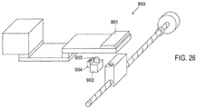
- Japanese Unexamined Patent Publication No. 2009-257988 discloses an examination apparatus 900 including an imaging unit 902 for imaging the flow path of a microchip 901, as shown in FIG. 26 .
- the imaging unit 902 includes a lens 903 and an illumination unit 904, and optically detects a sample flowing through the flow path of the microchip 901. In this way the sample passing through the monitoring area of the microchip 901 is subjected to image processing to analyze the liquid transfer state.
- Patent Document 1 Japanese Unexamined Patent Publication No. 2009-257988
- the imaging unit 902 images the sample flowing in the flow path of the microchip 901 to monitor the liquid transfer state in Japanese Unexamined Patent Publication No. 2009-257988 , it is difficult to image and monitor a highly transparent sample such as plasma or serum, or a liquid such as a reagent.
- the transfer purpose may not be achieved if a transfer failure such as a failure in the measured quantity of the liquid or a failure in transferring the liquid to a predetermined liquid holding portion occurs. Therefore, it is desirable to be able to monitor the liquid transfer state even with a highly transparent liquid that transmits light.
- the present invention allows monitoring of the transfer state of a liquid such as a highly transparent sample or reagent that transmits light.
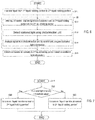
- the present invention is a liquid transfer monitoring method for monitoring the transfer state of a liquid (30) transferred in a flow path (10) having at least two liquid holding portions (20) and used in a sample measuring device, wherein the method includes a step of transferring the liquid (30) held in the first liquid holding portion (21) to a second liquid holding portion (22) connected to the first liquid holding portion (21), a step of acquiring information (40) related to scattered light intensity obtained by irradiating light (91) on an irregular inner surface (23) of at least one of the first liquid holding portion (21) and the second liquid holding portion (22) after the transfer of the liquid (30) is started; and a step of monitoring the liquid transfer to the second liquid holding portion (22) based on the information (40) related to the scattered light intensity.
- the light (91) is irradiated on the irregular inner surface of at least one of the first liquid holding portion (21) and the second liquid holding portion (22) to obtain information (40) related to the scattered light intensity.
- the irradiated irregular inner surface (23) scatters the irradiated light (91) in random directions.
- the irregularity of the inner surface (23) is covered with the liquid (30) and the difference in the refractive index is reduced and the light scattering is suppressed.
- the information (40) related to the scattered light intensity varies depending on the presence or absence of the liquid (30) as described above, it is possible to grasp whether the liquid (30) is being transferred to the liquid holding portion (20), and how far the liquid (30) is being transferred based on the obtained information (40) related to the scattered light intensity. In this way the liquid transfer state can be monitored even for liquids such as highly transparent samples and reagents that transmit light.
- the sample measuring device (100) is a sample measuring device that transfers a liquid (30) to a flow path (10) having at least two liquid holding portions (20) and performs measurement using the liquid (30), as shown in FIG. 1
- the sample measuring device (100) includes a liquid feeding unit (110) that applies an external force to the liquid (30) held in the first liquid holding portion (21) and transfers the liquid (30) to the second liquid holding portion (22) connected to the first liquid holding portion (21), an illumination unit (120) that irradiates light (91) on the irregular inner surface (23) of at least one of the first liquid holding portion (21) and the second liquid holding portion (22), a photodetection unit (130) for detecting scattered light (92) originating from light (91) irradiated on the inner surface (23), a control unit (140) for performing controls to acquire information (40) related to scattered light intensity based on signals from the photodetection unit (130) and determine a presence or absence of a liquid (30) within a liquid holding portion (20) based on
- the control unit (140) determines whether the liquid (30) is being transferred to the liquid holding portion (20), and how far the liquid (30) is being transferred based on the acquired information (40) related to the scattered light intensity, and this status can be grasped by a user. In this way the liquid transfer state can be monitored even for liquids such as highly transparent samples and reagents that transmit light.
- the liquid transfer state can be monitored even for liquids such as samples and reagents that have high transparency and transmit light.
- the liquid transfer monitoring method of the present embodiment is a method of monitoring the transfer state of a liquid 30 transferred in a flow path 10 having at least two liquid holding portions 20.
- the liquid 30 is a liquid used in the sample measuring device.
- the liquid can be a sample or reagent.
- the liquid 30 is, for example, a biological sample collected from a human being who is a subject.
- the liquid 30 may be blood, urine, bodily fluid, or other sample.
- the blood sample can be whole blood, serum, plasma and the like.
- the liquid 30 is mainly composed of a liquid and may include a solid component such as cells.
- the liquid 30 is, for example, a highly transparent liquid. Examples of such liquids are serum or plasma, urine, tissue fluid and the like.
- the liquid 30 may be a reagent used for measuring a sample.
- the reagent may be, for example, a labeling reagent, an enzyme reagent, a washing solution, a buffer solution or the like.
- the flow path 10 is a hollow space through which the liquid 30 can flow.
- the flow channel 10 has one or more inner surfaces and is formed in a tubular shape or a groove shape.
- the inner surface can be provided as a single surface if the flow channel 10 has a circular cross section, or provided as the same number of surfaces as the number of sides if the flow channel 10 has a polygonal shape.
- the liquid holding portion 20 is an empty space having a volume capable of containing a predetermined amount of liquid 30.
- the liquid holding portion 20 is a space in which the liquid 30 can be stored and has, for example, an inner bottom surface and one or more inner side surfaces.
- the liquid holding portion 20 also may be a space that has an inner upper surface and is closed off from the outside.
- the liquid holding portion 20 includes a first liquid holding portion 21 and a second liquid holding portion 22. The first liquid holding portion 21 and the second liquid holding portion 22 are in fluid communication with each other in the flow path 10.
- the first liquid holding portion 21 and the second liquid holding portion 22 includes the irregular inner surface 23.
- Both the first liquid holding portion 21 and the second liquid holding portion 22 also may have an inner surface 23 having irregularities.
- the inner surface 23 having irregularities is a roughened surface.
- the inner surface 23 is a surface including random fine irregularities.
- the irregular inner surface 23 is a surface that scatters light in random directions.
- the irregular inner surface 23 has a surface roughness of, for example, 1.3 ⁇ m or more and 6.9 ⁇ m or less.
- the surface roughness is an arithmetic mean roughness.
- the irregular inner surface 23 is formed by etching or the like when the hollow liquid holding portion 20 is formed on an object.
- the irregular inner surface 23 may be formed by a roughening treatment after the liquid holding portion 20 is formed.
- the irregular inner surface 23 may be any one of the inner bottom surface, the inner side surface, and the inner upper surface of the liquid holding portion 20, or may be the entire inner surface.
- the liquid delivery monitoring method of this embodiment includes the following steps S1 to S3.
- step S1 the liquid 30 moves in the flow path 10 by the action of an external force, for example.
- the external force is, for example, a capillary force.
- the external force is, for example, pressure.
- the pressure may be either air pressure or water pressure.
- the external force is, for example, centrifugal force.
- step S2 the illumination unit 120 irradiates a light 91 on the irregular inner surface 23.
- FIG. 1 shows an example in which the irregular inner surface 23 is formed on the second liquid holding portion 22, and the inner surface 23 of the second liquid holding portion 22 is irradiated with light 91.
- the irregular inner surface 23 also may be formed on the first liquid holding portion 21, and the inner surface 23 of the first liquid holding portion 21 may be irradiated with the light 91, or the first liquid holding portion 21 and the second liquid holding portion 22 such that the light 91 may be irradiated on both inner surfaces 23 of the liquid holding portions 21 and 22.
- the illumination unit 120 includes a light source such as an LED (light emitting diode), a laser light source, and other lamps.
- the photodetection unit 130 includes, for example, an optical sensor such as a photodiode and a photomultiplier tube, an image sensor, and the like. Information 40 related to the scattered light intensity is acquired from the signal of the light detection unit 130.
- the information 40 related to the scattered light intensity is information that allows the magnitude of the scattered light intensity to be comprehended.
- the information 40 related to the scattered light intensity may be the scattered light intensity itself.
- the information 40 related to the scattered light intensity also may be an index or an index that is acquired by analyzing the signal of the photodetection unit 130 and expresses the magnitude of the scattered light intensity.
- step S3 liquid transfer is monitored based on the information 40 related to the scattered light intensity.
- the monitoring of the liquid transfer is performed to collect information on the movement of the liquid 30.
- Monitoring the liquid transfer includes, for example, detecting the liquid 30 moving in the flow path 10.
- Monitoring the liquid transfer may include discovering undesirable conditions related to liquid transfer.
- the undesirable condition regarding the liquid transfer is, for example, the inclusion of air when the liquid 30 is metered, the liquid 30 remains in the flow path 10 and the like.
- Monitoring the liquid transfer includes, for example, monitoring the ratio of air originally mixed in the liquid 30.
- the monitoring of the liquid transfer includes, for example, monitoring the ratio of air mixed in the liquid 30 during the liquid transfer.
- Steps S2 and S3 can be performed during or after the liquid transfer in step S1.
- the monitoring of the liquid transfer is not only real-time monitoring during liquid transfer, but it also is possible to know afterwards that the liquid transfer was performed properly by comparing the information before and after the liquid transfer.
- the monitoring of the liquid transfer can be performed based on the difference in the information 40 related to the scattered light intensity. That is, as shown in FIG. 3 , when the liquid 30 is not present in the liquid holding portion 20 and the liquid holding portion 20 is filled with air, the irradiated light 91 is scattered by the irregular inner surface 23 to generated scattered light 92 in random directions. Therefore, the scattered light intensity is detected at a relatively high level.
- the irregularity of the inner surface 23 is covered with the liquid 30 and the difference in the refractive index is reduced, so that light scattering is suppressed. That is, the amount of light that is spectrally reflected by the surface of the liquid 30 that covers the inner surface 23, or is transmitted or absorbed without being scattered by the inner surface 23 even if it is transmitted through the surface of the liquid 30, increases and the intensity of scattered light decreases. Therefore, the scattered light intensity is detected at a relatively low level. As a result, it is possible to distinguish the region where the liquid 30 is present and the region where the liquid 30 is not present in the flow path 10.
- the relatively high or low here is the relative level when comparing the case where the liquid 30 does not exist in the liquid holding portion 20 and the case where the liquid holding portion 20 is filled with the liquid 30.
- the object in which the flow path 10 is formed is made of a resin material, metal, glass, or other substance, and has a refractive index different from the refractive index of air.
- the liquid 30 has a refractive index different from that of air. It is possible to monitor the liquid transfer even with a transparent liquid 30 by the difference in the information 40 on the scattered light intensity insofar as the refractive index is different.
- the material forming the flow path 10 is COP (cycloolefin polymer) and has a refractive index of about 1.50.
- the liquid 30 is, for example, blood plasma, and its refractive index can be considered to be equivalent to that of water, so that the refractive index is about 1.33.
- the refractive index of air is approximately 1.00.
- the light 91 is irradiated on the irregular inner surface 23 of at least one of the first liquid holding portion 21 and the second liquid holding portion 22 to obtain information 40 related to the scattered light intensity.
- the information 40 related to the scattered light intensity varies depending on the presence or absence of the liquid 30 as described above, it is possible to grasp whether the liquid 30 is being transferred to the liquid holding portion 20, and how far the liquid 30 is being transferred based on the obtained information 40 related to the scattered light intensity. In this way the liquid transfer state of the liquid 30 can be monitored even for liquids such as highly transparent samples and reagents that transmit light.
- the sample measuring device 100 is a sample measuring device that transfers the liquid 30 to the flow path 10 having at least two liquid holding portions 20 and performs measurement using the liquid 30.
- the sample measuring device 100 can monitor the transfer of the liquid 30 by executing the liquid transfer monitoring method of the present embodiment.
- the sample measurement device 100 includes a liquid transfer unit 110, an illumination unit 120, a photodetection unit 130, a control unit 140, and a measurement unit 145.
- the liquid transfer unit 110 applies an external force to the liquid 30 held by the first liquid holding portion 21, and transfers the liquid 30 to the second liquid holding portion 22 connected to the first liquid holding portion 21.
- the external force applied to the liquid 30 by the liquid transfer unit 110 is, for example, pressure or centrifugal force.
- the liquid transfer unit 110 includes, for example, a pump, and applies air pressure or water pressure to the liquid 30.
- the liquid transfer unit 110 includes, for example, a turntable, and rotates an object in which the flow path 10 is formed around a rotation axis.
- the liquid 30 in the first liquid holding portion 21 is moved toward the second liquid holding portion 22 by the centrifugal force.
- the liquid transfer unit 110 transfers the liquid 30 to the first liquid holding portion 21 by the centrifugal force.
- the liquid 30 contained in the first liquid holding portion 21 is transferred to the second liquid holding portion 22 by a capillary phenomenon.
- the object in which the flow path 10 is formed may be a container that contains the liquid 30, a part of a fluid circuit in the sample measuring device 100, or the like.
- the illumination unit 120 irradiates light 91 on the irregular inner surface 23 of at least one of the first liquid holding portion 21 and the second liquid holding portion 22.
- the photodetection unit 130 detects the scattered light 92 of the light 91 irradiating the inner surface 23.
- the photodetection unit 130 outputs a signal according to the detected light amount to the control unit 140.
- the control unit 140 acquires the information 40 related to the scattered light intensity based on the signal from the photodetection unit 130, and performs controls to determine the presence or absence of the liquid 30 in the liquid holding portion 20 based on the information 40 related to the scattered light intensity.
- the control unit 140 is a computer including a processor such as a CPU (Central Processing Unit), an FPGA (field-programmable gate array), and a storage unit such as a ROM (Read Only Memory) and a RAM (Random Access Memory).
- the control unit 140 executes controls for determining the presence or absence of the liquid 30 by the processor executing a program stored in the storage unit.
- the measurement unit 145 is configured to perform a measurement using the liquid 30.
- the measurement method is not particularly limited.
- the liquid 30 may be a sample used for measurement or a reagent mixed with the sample.
- the reagent reacts with the test substance in the sample to cause a directly or indirectly measurable change in the test substance.
- the reagent emits light depending on the amount of the test substance. Luminescence is, for example, chemiluminescence or fluorescence.
- the reagent includes, for example, a labeling substance that specifically binds to the test substance.
- the labeling substance produces a signal that can be measured by the measurement unit 145, for example. According to the measurement item, the presence or absence of the test substance, the amount or concentration of the test substance, and the size and shape of the particulate test substance can be measured by detecting the signal.
- the labeling substance includes a chemiluminescent substance or fluorescent substance, radioactive isotope and the like.
- the reagent also may be one that develops color according to the amount of the test substance, or one that causes turbidity depending on the amount of the test substance.
- the measurement unit 145 includes a photodetector such as a photomultiplier tube, a photocell, or a photodiode when detecting light emission.
- the measurement unit 145 includes a radiation detector such as a scintillation counter when detecting radiation.
- the measurement unit 145 includes a light source and a light receiving element when detecting fluorescence, color, or turbidity.
- the control unit 140 may simply determine the presence or absence of the liquid 30 in any of the liquid holding portions 20.
- the control unit 140 also may be configured to perform controls to monitor the liquid transfer to the second liquid holding portion 22 by determining the presence or absence of the liquid 30 based on the information 40 on the scattered light intensity. In this way, it is possible to monitor whether the liquid transfer from the first liquid holding portion 21 to the second liquid holding portion 22 is properly performed in the sample measurement.
- the control unit 140 transfers the liquid 30 by controlling the liquid transfer unit 110 in step S1 of FIG. 2 .
- the control unit 140 causes the illumination unit 120 to irradiate light 91 on the inner surface 23.
- the photodetection unit 130 detects the scattered light 92.
- the control unit 140 acquires a signal from the photodetection unit 130.
- the control unit 140 acquires the information 40 on the scattered light intensity based on the signal acquired from the photodetection unit 130.
- the control unit 140 monitors the liquid transfer to the second liquid holding portion 22 based on the information 40 related to the scattered light intensity.
- the details of the monitoring of the liquid transfer performed by the control unit 140 are the same as the above-mentioned liquid transfer monitoring method.
- the control unit 140 determines whether the liquid 30 is being transferred to the liquid holding portion 20, and how far the liquid 30 is being transferred based on the acquired information 40 related to the scattered light intensity, and this status can be grasped by a user. In this way the liquid transfer state of the liquid 30 can be monitored even for liquids such as highly transparent samples and reagents that transmit light.
- the information 40 related to the scattered light intensity is obtained by the photodetection unit 130 detecting the scattered light 92, and the control unit 140 connected to the photodetection unit 130 analyzing the signal from the photodetection unit 130.
- the scattered light 92 generated from the liquid holding portion 22 can be detected, and the information 40 related to the scattered light intensity can be acquired based on the detected signal.
- the light detection unit 130 includes an imaging unit 131 having an image sensor, for example.
- the control unit 140 (see FIG. 1 ) acquires and analyzes the captured image of a liquid holding portion 20 as a signal from the light detection unit 130.
- the analysis performed by the control unit 140 is image analysis.
- the control unit 140 acquires the information 40 related to the scattered light intensity by image analysis.
- the information 40 related to the scattered light intensity can be acquired from the image of the liquid holding portion 20.
- the distribution of the scattered light intensity corresponding to the position in the liquid holding portion 20 can be analyzed to acquire the information 40 related to the scattered light intensity which is suitable for monitoring the liquid 30.
- the irregular inner surface 23 is the inner bottom surface 24 of the liquid holding portion 20.
- the inner bottom surface 24 is the surface having the largest area. Therefore, since the surface that generates the scattered light 92 becomes large, the information 40 related to the scattered light intensity can be acquired more easily.
- step S2 (see FIG. 2 ) of obtaining the information 40 related to the scattered light intensity
- the inner irregular bottom surface 24 is obliquely irradiated with the light 91 and the scattered light 92 is detected by the imaging unit 131 at a position above the inner bottom surface 24. That is, the illumination unit 120 obliquely irradiates the irregular inner bottom surface 24 with the light 91, and the imaging unit 131 detects the scattered light 92 at a position above the inner bottom surface 24.
- the imaging unit 131 can substantially detect just the scattered light 92. Therefore, the information 40 related to the scattered light intensity can be acquired accurately.
- the illumination unit 120 is configured as dark-field illumination for the imaging unit 131.
- the illumination unit 120 irradiates the light 91 in an oblique direction so that the generated light 91 is not spectrally reflected and is not received by the imaging unit 131.
- the imaging unit 131 is arranged directly above the inner bottom surface 24 and captures an image facing downward.
- the irradiation angle 95 of the illumination unit 120 is set so that the reflected optical axis 94 that is spectrally reflected with respect to the outgoing optical axis 93 of the illumination unit 120 passes through the outside of the light receiving part of the imaging unit 131. In this way the spectrally reflected light is not substantially detected by the imaging unit 131, and substantially only the scattered light 92 is detected by the imaging unit 131.
- the liquid holding portion 20 also is formed so as to extend in the A direction.
- the illumination unit 120 is provided so as to emit the light 91 in the direction along the A direction in which the liquid holding portion 20 extends.
- FIG. 5 is a schematic view of the liquid holding portion 20 of FIG. 3 viewed from the A direction.
- the illumination unit 120A irradiates the liquid holding portion 20 with light 91 from above the extension line along the A direction to the irregular inner bottom surface 24 of the liquid holding portion 20.
- the broken line in FIG. 5 indicates the irradiation range of the light 91.
- the scattered light 92 can be generated by irradiating the wide area of the inner bottom surface 24 with the light 91 without causing a shadow due to the inner side surface 25 of the liquid holding portion 20.
- the illumination unit 120B of FIG. 5 irradiates the inner bottom surface 24 of the liquid holding portion 20 with light from an upper position which is displaced in the B direction orthogonal to the A direction relative to the liquid holding portion 20.
- the illumination unit 120 is provided so as to emit light in the direction along the direction A in which the liquid holding portion 20 extends.
- the liquid holding portion 20 is formed as a space capable of containing a liquid by covering a slot which has the inner bottom surface 24 and the pair of inner side surfaces 25 with the cover member 26 that has a light transmitting property.
- control unit 140 controls the liquid transfer unit 110 to transfer the liquid 30 in the first liquid holding portion 21 to the second liquid holding portion 22.
- the step S2 of acquiring the information 40 relating to the scattered light intensity of FIG. 2 specifically includes steps S12 to S14 of FIG. 6 .
- step S12 the control unit 140 causes the illumination unit 120 to irradiate the light 91 on the first liquid holding portion 21 and/or the second liquid holding portion 22.
- steps S12 to S14 for acquiring the information 40 related to the scattered light intensity the light 91 is irradiated on the irregular inner surface 23 after the transfer of the liquid 30 is completed.
- step S13 the control unit 140 causes the light detection unit 130 to detect scattered light.
- the control unit 140 acquires the detection signal of the scattered light 92 from the light detection unit 130.
- step S14 the control unit 140 acquires the information 40 related to the scattered light intensity.
- the pixel value of each pixel in the captured image reflects the scattered light intensity.
- the control unit 140 performs image processing on a region of the captured image in which the inner surface 23 of the first liquid holding portion 21 and/or the second liquid holding portion 22 is imaged to extract information 40 related to the scattered light intensity on the inner surface 23. Note that the relative position of the light detection unit 130 with respect to the inner surface 23 is known, and the coordinates of the inner surface 23 in the captured image are known. Step S2 of FIG. 2 is completed by the steps S12 to S14.
- the image analysis is locally performed on a region including at least one of the first liquid holding portion 21 and the second liquid holding portion 22.
- the control unit 140 extracts only the region including at least one of the first liquid holding portion 21 and the second liquid holding portion 22 from the captured image, and acquires the information 40 related to the scattered light intensity.
- the information 40 related to the scattered light intensity is, for example, the pixel value of the area where the inner surface 23 is imaged.
- the area where the inner surface 23 is imaged may be composed of a large number of pixels.
- the information 40 related to the scattered light intensity may be a representative value of the pixel values of the pixel group included in the region where the inner surface 23 is imaged.
- the representative value may be, for example, a total value, an average value, a median value, or the like of each pixel value.
- the information 40 related to the scattered light intensity may be the pixel value of each pixel in the region where the inner surface 23 is imaged.
- the information 40 related to the scattered light intensity is numerical information corresponding to the number of pixels in the area where the inner surface 23 is imaged.
- step S15 the control unit 140 determines whether there is a liquid supply abnormality to the second liquid holding portion 22 based on the information 40 related to the scattered light intensity acquired in step S14. That is, when the liquid 30 is transferred from the first liquid holding portion 21 to the second liquid holding portion 22, the control unit 140 determines whether a liquid transfer abnormality has occurred (that is, whether the liquid 30 has been normally transferred) .
- Step S15 corresponds to step S3 of FIG. 2 .
- the step of monitoring the liquid transfer may include the step of determining whether there is a liquid transfer abnormality.
- FIG. 7 shows an example of steps for determining the presence or absence of liquid transfer abnormality.
- step S21 of FIG. 7 the control unit 140 determines whether the scattered light intensity is less than or equal to a threshold value.
- the control unit 140 compares the representative value with a threshold value.
- the threshold value is set at a value between a relatively high level of scattered light intensity when the liquid holding portion 20 is filled with air without the liquid 30 and relatively low level of scattered light intensity when the liquid holding portion 20 filled with the liquid 30.
- step S21 When the scattered light intensity is less than or equal to a threshold value in step S21, the control unit 140 advances the processing to step S22 and determines that "no liquid transfer abnormality to the second liquid holding portion 22 has occurred". That is, since the detected scattered light intensity corresponds to the scattered light intensity of a relatively low level when the liquid holding portion 20 is filled with the liquid 30, it can be determined that the liquid 30 has been normally transferred to the second liquid holding portion 22.
- the control unit 140 advances the process to step S23, and determines the "liquid transfer to the second liquid holding portion 22 is abnormal". That is, since the detected scattered light intensity corresponds to a relatively high level of scattered light intensity when the liquid 30 is not present and the liquid holding portion 20 is filled with air, it can be determined that the liquid 30 has not normally transferred to the second liquid holding portion 22 and there is a region filled with air, or the entire second liquid holding portion 22 remains filled with air.
- FIG. 8 shows another example of the step of determining the presence/absence of liquid transfer abnormality.
- a property of the liquid 30 to be transferred is determined in addition to the presence/absence of liquid transfer abnormality.
- a property of the liquid 30 is different from the assumed state.
- the difference in a property of the liquid 30 may be that the optical characteristics of the liquid 30, such as turbidity of the liquid 30 and the refractive index thereof, is different from that which is expected.
- a property of the liquid 30 changes due to an abnormal property of the liquid 30 that is a sample collected from a patient due to a disease or the like, or a chemical change of the liquid 30 due to an external environmental factor.
- a property abnormality of the liquid 30 if the liquid 30 is plasma the the property abnormality may be chyle, hemolysis, jaundice, and the like.
- the property of the liquid 30 is determined based on the information 40 related to the scattered light intensity.
- the control unit 140 makes a determination based on a first threshold value and a second threshold value.
- the first threshold is set to a value between a relatively low level of scattered light intensity and an intermediate level of scattered light intensity.
- the second threshold is set to a value between a relatively high level of scattered light intensity and an intermediate level of scattered light intensity.
- step S31 of FIG. 8 the controller 140 determines whether the scattered light intensity is higher than the second threshold value.
- step S31 when the scattered light intensity is higher than the second threshold value, the control unit 140 advances the process to step S32 and determines that "there is a liquid transfer abnormality to the second liquid holding portion 22". That is, since the detected scattered light intensity corresponds to a relatively high level of scattered light intensity, it can be determined that the liquid transfer is abnormal, as in step S23 of FIG. 7 .
- step S31 when the scattered light intensity is less than or equal to the second threshold value in step S31, the control unit 140 proceeds to step S33 and determines whether the scattered light intensity is higher than the first threshold value.
- step S33 when the scattered light intensity is higher than the first threshold value, the control unit 140 advances the processing to step S34, and determines "there is no abnormality in the liquid transfer to the second liquid holding portion 22 and there is an abnormality in the liquid property. That is, since the detected scattered light intensity corresponds to an intermediate level between the first threshold value and the second threshold value, it can be determined that the property of the liquid 30 is abnormal. Since the scattered light intensity is less than or equal to the second threshold value, it also can be determined that the liquid 30 is normally transferred to the second liquid holding portion 22.
- the control unit 140 advances the process to step S35, and determines "there is no abnormality in the liquid transfer to the second liquid holding portion 22 (the liquid property is also abnormal)". That is, since the detected scattered light intensity corresponds to a relatively low level of scattered light intensity, it is determined that the liquid 30 has been transferred to the second liquid holding portion 22 without abnormality as in step S22 of FIG.7 . Then, since the detected scattered light intensity corresponds to a level lower than the intermediate level, it can be determined that the property of the liquid 30 is normal.
- steps S43 and S47 for acquiring information related to the scattered light intensity are performed before the liquid 30 is transferred to the second liquid holding portion 22 and after the liquid 30 is transferred.
- the information 40 related to the scattered light intensity before and after the transfer of the liquid 30 can be acquired. Therefore, it is possible to evaluate how the state of the second liquid holding portion 22 has changed due to the liquid transfer.
- step S41 the control unit 140 controls the illumination unit 120 to cause the light from the illumination unit 120 to irradiate the second liquid holding portion 22 before transfer.
- step S42 the control unit 140 causes the light detection unit 130 to detect scattered light.
- step S43 the control unit 140 acquires the information 41 related to the first scattered light intensity by analyzing the detected scattered light.
- the information 41 related to the first scattered light intensity before transfer is acquired from the second liquid holding portion 22.
- step S44 the control unit 140 controls the liquid transfer unit 110 to transfer the liquid 30 of the first liquid holding portion 21 to the second liquid holding portion 22 by an external force.
- step S45 the control unit 140 controls the illumination unit 120 to cause the light from the illumination unit 120 to irradiate the second liquid holding portion 22 after liquid transfer.
- step S46 the control unit 140 causes the light detection unit 130 to detect scattered light.
- step S47 the control unit 140 acquires the information 42 related to the second scattered light intensity by analyzing the detected scattered light.
- step S48 the control unit 140 determines the presence/absence of an abnormality during the liquid transfer to the second liquid holding portion 22 based on the information 41 on the first scattered light intensity acquired in step S43 and the information 42 on the second scattered light intensity acquired in step S47.
- the information 40 related to the scattered light intensities acquired before and after the transfer of the liquid 30 are compared to determine whether there is a liquid supply abnormality.
- the control unit 140 acquires the information 40 related the scattered light intensity before the liquid 30 is transferred to the second liquid holding portion 22 and after the liquid 30 is transferred, and determines the presence/absence if a liquid transfer abnormality by comparing information 40 relating to the scattered light intensities acquired before and after the liquid transfer.
- FIG. 10 shows an example of steps for determining the presence or absence of a liquid transfer abnormality.
- the control unit 140 determines whether the first scattered light intensity is higher than the second scattered light intensity.
- step S51 when the first scattered light intensity is higher than the second scattered light intensity, the control unit 140 advances the process to step S52, and determines there is "no abnormality in liquid transfer to the second liquid holding portion 22". That is, since the scattered light intensity detected after the liquid transfer is lower than that before the transfer, the second liquid holding portion 22 is filled with the air before the transfer, and it can be determined that the second liquid holding portion 22 has changed state to being filled with the liquid 30.
- the control unit 140 advances the process to step S53, and determines the"the liquid transfer to the second liquid holding portion 22 is abnormal". That is, since the scattered light intensity detected after the liquid transfer is equal to or higher than that before the transfer, the second liquid holding portion 22 is in the state filled with the air before the transfer, it can be determined that the liquid 30 has not been transferred since the state has not changed.
- the sample measuring device 100 is an immunoassay device that detects a test substance in a sample using an antigen-antibody reaction, and measures the test substance based on the detection result.
- the detection device 100 is, for example, a compact detection device for PoC (Point of Care) examination, and is configured to be able to execute a measurement operation by a simple operation.
- PoC Point of Care
- the sample measuring device 100 performs measurement using a cartridge 300 in which the flow path 10 is formed.
- the cartridge is a replaceable component that has the functions necessary for detecting the test substance contained in the sample.
- the sample measuring device 100 transfers the liquid 30 in the cartridge 300 as part of the measurement operation.
- the sample measuring device 100 monitors the liquid transfer of the liquid 30 in the cartridge 300.
- the cartridge 300 is a replaceable consumable item. That is, the cartridge 300 is discarded after being used for measurement a preset number of times.
- the cartridge 300 can be used once or several times.
- the type of reagent contained in the cartridge 300 differs depending on the measurement item. There may be a plurality of variations of the cartridge 300 for each measurement item.
- the cartridge 300 also may be capable of measuring a plurality of different measurement items.
- the cartridge 300 has, for example, a flat plate shape with a space formed inside.
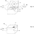
- FIG. 11 shows an example in which the cartridge 300 is a disk-shaped cartridge having a disc shape.
- the cartridge 300 includes a plurality of chambers capable of containing the liquid 30.
- the cartridge 300 includes the flow channel 10 having a plurality of liquid holding portions 20 as shown in FIG. 1 .
- the liquid 30 contained in the liquid holding portion 20 is a sample.
- the liquid holding portion 20 may store a reagent according to the measurement item of the sample.
- the sample measuring device 100 includes a housing 150 that can accommodate the cartridge 300.
- the housing 150 includes a main body 151 and a lid 152.
- the lid 152 is provided so as to cover substantially the entire upper surface of the main body 151.
- a placement unit 153 is provided on the upper surface of the main body 151 in which the cartridge 300 is placed.
- the lid 152 is provided so as to be oscillatable relative to the main body part 151 between a state in which the placement unit 153 shown in FIG. 11 is opened, and a state in which the placement unit 153 shown in FIG. 12 is covered.
- the control unit 140 starts the measurement operation.
- the disk-type cartridge may be installed by a slot loading method in which the cartridge 300 is inserted from an insertion opening formed in the housing 150, or a tray loading method in which the cartridge 300 is placed on a tray that moves inside or outside the housing 150.
- the internal structure of the sample measuring device 100 will be described with reference to FIG. 13 .
- a support member 154 that supports the cartridge 300 from below is arranged in the placement unit 153.
- the support member 154 is composed of, for example, a turntable.
- the support member 154 is provided on the upper end portion of a rotating shaft 112 of a rotating mechanism 111.
- the cover 152 is provided with a clamper 155.
- the clamper 155 rotatably supports the central portion of the upper surface of the cartridge 300 installed on the support member 154 when the lid 152 is closed.
- the cartridge 300 is supported by being interposed between the support member 154 and the clamper 155.
- the sample measurement device 100 includes a liquid transfer unit 110, an illumination unit 120, a light detection unit 130, a control unit 140, and a measurement unit 145 in a housing 150.
- the sample measuring device 100 includes a magnet drive unit 161, an opening unit 162, a heater 163, and a temperature sensor 164 in the housing 150.
- the liquid transfer unit 110 includes a rotation mechanism 111.
- the rotating mechanism 111 includes a rotating shaft 112 and a drive unit 113 including a motor.
- the rotation mechanism 111 drives the drive unit 113 to rotate the cartridge 300 installed on the support member 154 around the rotation shaft 112.
- the rotation mechanism 111 includes an encoder 114 for detecting the rotation angle of the drive unit 113, and an origin sensor 115 for detecting the origin position of the rotation angle. It is possible to move the cartridge 300 to an arbitrary rotation position by driving the drive unit 113 based on the detection angle of the encoder 114 with the detection position of the origin sensor 115 as a reference.
- the liquid transfer unit 110 transfers the liquid 30 by rotating the cartridge 300 around the rotation shaft 112.
- the liquid transfer unit 110 executes at least a part of the measurement process by the rotation mechanism 111.
- the rotation mechanism 111 rotates to centrifuge the blood sample, transfer the sample, and transfer reagent to the reaction chambers 314 to 319 (see FIG. 16 ) inside the cartridge 300; the reagent and the sample are stirred, and the magnetic particles are circumferentially transferred between the reaction chambers 314 to 319.
- the magnet drive unit 161 includes a magnet 161a and has a function of moving magnetic particles inside the cartridge 300 in the radial direction.
- the magnet drive unit 161 is arranged below the arrangement unit 153, and is configured to move the magnet 161a in the radial direction.
- the magnet drive unit 161 also is configured to move the magnet 161a in a direction of approaching or separating from the cartridge 300. By bringing the magnet 161a closer to the cartridge 300, the magnetic particles in the cartridge 300 are magnetized, and by moving the magnet 161a away from the cartridge 300, the magnetism of the magnetic particles is released.
- the opening unit 162 projects a pin member 162a that can be advanced and retracted toward the cartridge 300 from above the cartridge 300 arranged in the placement unit 153 so as to abut against the cartridge 300 and press a sealing member 350 inside the cartridge 300 (see FIG. 16 ). After opening, the opening unit 162 moves the pin member 162a away from the cartridge 300 to the retracted position at which the pin member 162a is in non-contact.
- a heater 163 is provided at a position directly below the cartridge 300 arranged in the placement unit 153 and a position immediately above the cartridge 300, respectively.
- the heater 163 heats the sample contained in the cartridge 300 to a predetermined reaction temperature to accelerate the reaction between the sample and the reagent.
- the temperature sensor 164 detects the temperature of the cartridge 300 by infrared rays.
- the measuring unit 145 includes a light receiving unit at a position facing the cartridge 300 arranged in the placement unit 153 through the opening formed in the main body 151. In this way the measuring unit 145 detects the light generated from the reaction chamber 319 (see FIG. 16 ) from the light receiving unit.
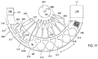
- the measurement unit 145 includes a detector 145a that measures the light derived from the test substance moved to the detection position 146 (see FIG. 17 ).
- the detector 145a is composed of, for example, a photomultiplier tube, a phototube, a photodiode, or the like.
- the detector 145a outputs a pulse waveform corresponding to the reception of light particles, that is, photons.
- the measurement unit 145 includes an internal circuit, counts photons at regular intervals based on the output signal of the detector 145a, and outputs the count value.
- the light detection unit 130 includes an imaging unit 131.
- the imaging unit 131 is provided so as to face the upper surface of the cartridge 300 installed on the support member 154.
- the imaging unit 131 acquires the image of the cartridge 300.
- the imaging unit 131 includes, for example, a CCD image sensor, a CMOS image sensor, and the like.
- the imaging unit 131 acquires, for example, a color image.
- the imaging unit 131 acquires an image in the form of a still image, for example.
- the illumination unit 120 has a light source including, for example, a light emitting diode.
- the illumination unit 120 generates illumination light when capturing an image.
- the illumination unit 120 is configured as dark-field illumination for the imaging unit 131.
- the imaging unit 131 and the illumination unit 120 are fixed to the lid 152.
- the imaging unit 131 directly faces the upper surface of the cartridge 300 via a hole provided in the lid 152.
- the illumination unit 120 also directly faces the upper surface of the cartridge 300 via a hole provided in the lid 152. Therefore, the imaging range 132 (see FIG. 17 ) of the imaging unit 131 does not move.
- Each unit such as the liquid holding portion 20 that is the monitoring target of the cartridge 300 is moved into the imaging range 132 by the rotation of the rotating mechanism 111.
- the imaging unit 131 may be movably provided in the housing 150.
- the imaging unit 131 also may be provided in the main body 151.
- the position of the imaging unit 131 is not particularly limited insofar as it can image the monitoring target.
- the sample measuring device 100 shown in FIG. 13 includes an operation unit 171 (see FIG. 12 ) that receives a user operation when opening the lid 152, a detection unit 172 that detects opening and closing of the lid 152, and a lock mechanism 173 that engages with and locks the lid 152.
- the lid 152 is biased in the opening direction by a force exerting member (not shown). When the lock of the lid 152 in the closed state is released, the lid 152 is opened by the exerted force.
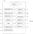
- FIG. 14 shows a controllable configuration of the sample measuring device 100.
- the sample measuring device 100 includes a control unit 140.
- the control unit 140 includes, for example, a processor and a memory.
- the processor is composed of, for example, a CPU, an MPU, and the like.
- the memory is composed of, for example, a ROM and a RAM.
- the control unit 140 receives a signal from each unit of the sample measuring device 100 and controls each part of the sample measuring unit 100.
- the sample measuring device 100 includes a storage unit 141.
- the storage unit 141 stores at least the image of the monitoring target captured by the imaging unit 131, and the measurement result data 405 (see FIG. 15 ).
- the storage unit 141 is composed of, for example, a flash memory, a hard disk, or the like.
- the control unit 140 analyzes the captured image.
- the control unit 140 acquires the information 40 related to the scattered light intensity by performing image analysis on the image of the liquid holding portion 20.
- the control unit 140 monitors the liquid transfer based on the acquired information 40 on the scattered light intensity.
- the control unit 140 may individually include a processor for controlling each unit of the sample measuring device 100 and a processor for image processing.
- the sample measuring device 100 includes a communication unit 142.
- the communication unit 142 can transmit information to an external device and receive information from the external device.
- the communication unit 142 includes, for example, a communication module and an interface for external connection.
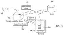
- the communication unit 142 is capable of performing wired or wireless communication with a terminal 500 capable of communicating with the sample measuring device 100 and with a server 600 via a network.
- the communication unit 142 may be capable of communicating in multiple types of communication methods.
- the connection to the network is, for example, a wired LAN or a wireless LAN.
- the connection with the terminal 500 may be made by a wired LAN, a wireless LAN, Bluetooth (registered trademark), another NFC (near field communication), or the like.
- the connection with the terminal 500 also may be performed by an interface for external connection such as USB.
- the server 600 is a server that manages the measurement result data 405.
- the control unit 140 can transmit the measurement result data 405 using the cartridge 300 to at least one of the terminal 500 and the server 600 by the communication unit 142.
- the user can browse the measurement results by accessing the server 600 with any device that can be connected to the network.
- the terminal 500 includes, for example, a tablet terminal, a mobile information terminal such as a smartphone, and an information terminal such as a PC (personal computer).
- the terminal 500 causes the display unit 510 to display the measurement result data 405.
- the terminal 500 also receives a user operation input via a user interface such as a button displayed on the display unit 510.
- the input operation is detected by a touch panel on a tablet terminal or a mobile information terminal such as a smartphone, and on a terminal such as a PC via a mouse, a keyboard or other input devices.
- the sample measuring device 100 includes a notification unit 143 (see FIG. 11 ) that notifies of the status of the device.
- the notification unit 143 notifies of the state of the device by at least one of the color of light, lighting of light, blinking of light, and sound. That is, the notification unit 143 may be an indicator that gives notification by light emission, a speaker or a buzzer that gives notification by sound. Note that the notification of the state of the device can be performed not only in the notification unit 143 but also in a mode in which the display unit 510 of the terminal 500 displays the information through communication via the communication unit 142.
- the cartridge 300 is a disk-type cartridge including a plate-shaped and disk-shaped substrate 301.
- Each part in the cartridge 300 is formed by bonding a through hole formed on the substrate 301 and a film (not shown) covering the entire surface including the through hole on both surfaces of the substrate 301 to each other.
- the film attached to the substrate 301 is formed of a light-transmitting member.
- the substrate 301 has a thickness such that the temperature of the cartridge 300 can be easily adjusted by the heater 163.
- the thickness of the substrate 101 is several millimeters, specifically, about 1.2 mm.
- a hole 302 and a flow path 10 are formed in the substrate 301.
- the hole 302 penetrates the substrate 301 at the center of the substrate 301.
- the cartridge 300 is installed in the sample measuring device 100 so that the center of the hole 302 coincides with the center of the rotating shaft 112.
- the radial direction and the circumferential direction of the circle having the hole 302 as the center are referred to as the "radial direction” and the “circumferential direction", respectively.
- the flow path 10 includes nine chambers 310, a plurality of passages 330, six storage units 341, one storage unit 342, and an port 343.
- the liquid 30 is injected into the port 343.
- the liquid 30 is a blood sample of whole blood collected from a subject.
- the passage 330 includes passages 331 to 336, and is configured to fluidly connect the plurality of chambers 310, the storage units 341 and 342, and the port 343. Some or all of these passageways 330 and chambers 310 have an inner surface 23 with irregularities.
- the surface of the substrate 301 other than the flow channel 10 is a smooth surface.
- the smooth surface here means that the surface roughness is significantly smaller than that of the inner surface 23 having irregularities.
- the chamber 310 is a space that can contain a liquid.
- the nine chambers 310 are arranged in the circumferential direction near the outer periphery of the substrate 301.
- the plurality of chambers 310 include liquid chambers 311-313 and reaction chambers 314-319.
- the liquid chamber 311 receives the supplied liquid 30.
- the liquid chamber 311 is connected to the port 343 via the passage 331.
- the blood sample injected from the port 343 is transferred to the liquid chamber 311 via the passage 331 by the centrifugal force generated by the rotation of the cartridge 300.
- the liquid chamber 312 receives an excess amount of the liquid 30 that exceeds a certain amount in the liquid chamber 311.
- the liquid chamber 312 is arranged radially outside the liquid chamber 311 and is connected to the liquid chamber 311 via a passage 332.
- the liquid 30 flowing into the liquid chamber 311 from the passage 331 is accumulated in order from the radially outer side by the centrifugal force, and the liquid surface position in the radial direction moves inward as the amount of stored liquid increases.
- the liquid surface position in the liquid chamber 311 reaches the passage 332, a larger amount of the liquid 30 is moved to the liquid chamber 312 by the action of centrifugal force. Therefore, the amount of the liquid 30 stored in the liquid chamber 311 can be quantified to a constant amount by previously injecting the liquid 30 in an amount exceeding the certain amount.
- the liquid component and the solid component contained in the liquid 30 in the liquid chamber 311 are centrifuged by rotating the cartridge 300.
- the liquid 30 in the liquid chamber 311 is separated into plasma, which is a liquid component, and blood cells and other non-liquid components, which are solid components, by centrifugation.
- the liquid 30 after the separation process is plasma.
- the plasma separated in the liquid chamber 311 moves to the passage 333 due to the capillary phenomenon.
- the width of the passage 333 is narrowed by the connecting portion 333b immediately before the reaction chamber 314, and the plasma fills the inside of the passage 333 until just before the reaction chamber 314.
- the passage 333 extends radially inward from the liquid chamber 311, bends at the bent portion 333a, extends radially outward, and is connected to the reaction chamber 314.
- the centrifugal force is applied by the rotation while the plasma fills the passage 333, the plasma in the region on the reaction chamber 314 side is transferred to the reaction chamber 314 with the bent portion 333a as a boundary.
- the volume of the passage 333 from the bent portion 333a to the tip determines a predetermined amount of plasma to be transferred to the reaction chamber 314.
- the liquid chamber 313 is provided to prevent the liquid 30 in the liquid chamber 311 after being transferred to the reaction chamber 314 from being transferred to the reaction chamber 314 again.
- the liquid chamber 313 is arranged radially outside the liquid chamber 311 and is connected to the liquid chamber 311 via a passage 334.
- passage 334 is also filled with liquid 30.
- the liquid 30 is transferred from the liquid chamber 311 to the liquid chamber 313 by the siphon principle until the liquid surface position reaches a balanced position. As a result, the amount of liquid in the liquid chamber 311 decreases, so that once the plasma has been transferred to the reaction chamber 314, the liquid 30 in the liquid chamber 311 is suppressed from being transferred to the reaction chamber 314.
- reaction chambers 314, 315, 316, 317, 318, 319 having substantially the same shape are arranged side by side in the circumferential direction so as to be adjacent to each other, and each is connected through a passage 335 extending in the circumferential direction.
- the test substance is sequentially transferred one by one from the one side (reaction chamber 314 side) to the other side (reaction chamber 319 side) via the passage 330.
- Reagents stored in the corresponding storage units 341 are transferred to the reaction chambers 314 to 319 via the passages 336.
- the liquid 30 containing the test substance also is transferred to the reaction chamber 314 via the passage 333.
- the liquid 30 containing the test substance is plasma centrifuged from whole blood.
- Magnetic particles MP are enclosed in the reaction chamber 314.
- the test substance contained in the liquid 30 is made into a complex with the magnetic particles MP. Therefore, after the reaction chamber 314, the test substance bound to the magnetic particles MP is transferred to the passage 335 and the other chamber 310 by the combination of the rotation of the cartridge 300 and the action of the magnetic force.
- the passage 335 includes six radial regions 335a extending in the radial direction and one arc-shaped circumferential region 335b extending in the circumferential direction.
- the circumferential region 335b is connected to the six radial regions 335a.
- the six radial regions 335a are connected to the reaction chambers 314 to 319, respectively.
- the six storage units 341 are connected to the passage 335 via a passage 336 in the radial direction.
- the six storage units 341 are arranged side by side in the radial direction with the corresponding reaction chambers 314 to 319.
- the housing 342 is connected to the reaction chamber 319 mainly via a passage 336 extending in the radial direction.
- a total of seven storage units 341 and 342 are arranged on the inner peripheral side of the cartridge 300, and a total of six reaction chambers 314 to 319 are arranged on the outer peripheral side of the cartridge 300.
- Each of the receiving unit 341 and the receiving unit 342 accommodates a reagent, and includes a sealing body 350 on the upper surface on the inner side in the radial direction.
- the sealing body 350 is configured to be opened by being pressed from above by the opening unit 162 (see FIG. 13 ) of the sample measuring device 100. Before the sealing body 350 is opened, the reagent in the container 341 does not flow into the passage 336. When the sealing body 350 is opened, the reagent in the container 341 can flow into the passage 336. When the cartridge 300 is rotated after the stopper is opened, the reagent moves to the corresponding reaction chambers 314 to 319 by the centrifugal force.
- the storage unit 341 and the storage unit 342 each accommodate a reagent that can be measured once. That is, the cartridge 300 is a one-time-use measurement cartridge capable of performing one-time measurement on the test substance.
- the measurement process includes a process of stirring the test substance and the reagent in the chamber by rotating the cartridge 300. That is, the rotation speed of the cartridge 300 is changed, and acceleration and deceleration are alternately repeated. By the acceleration/deceleration, the liquid is moved back and forth in the chamber 310 in the circumferential direction, and the complex is dispersed in the reagent.
- the test substance and the labeling substance are carried on the magnetic particles MP in the chamber 310, and the magnetic particles MP are sequentially transferred to a plurality of chambers, so that the reagent and the test substance are stirred in the respective reaction chambers 314 to 319. Finally, the magnetic particles carrying the test substance and the labeling substance are moved to the reaction chamber 319, and the labeling substance is detected by the sample measuring device 100, whereby the measurement is performed.
- the flow channel 10 in the example of FIG. 16 is formed only in a region of approximately one third of the substrate 301.
- the present invention is not limited to this, and two more channels 10 may be formed in the remaining two-thirds region of the substrate 301, and three channels 10 may be provided in the substrate 301.
- one flow path 10 may be formed over a region larger than a one-third region of the substrate 301.
- the measurement process of the same measurement item may be performed in each flow channel 10, or the measurement process of different measurement items may be performed.
- the numbers and shapes of the chambers 310 and the passages 330 also are not limited to those shown in FIG. 16 .
- the configuration of each part of the flow channel 10 is determined according to the content of the sample processing assay performed in the flow channel 10.
- the cartridge 400 is provided with the identifier 400.
- the identifier 400 is an information recording medium from which information can be read by imaging.
- the identifier 400 is a two-dimensional code.
- the identifier 400 is provided on the cartridge 300 by attaching a label on which a two-dimensional code is printed or by directly printing the two-dimensional code on the surface of the cartridge 300.
- the identifier 400 also may be a barcode.
- the control unit 140 reads the information recorded in the identifier 400 by acquiring the image of the identifier 400 with the imaging unit 131.
- the control unit 140 controls the measurement operation based on the read information.
- the identifier 400 includes at least one of information for specifying a measurement item that can be measured using the cartridge 300, information about a reagent contained in the cartridge 300, and identification information for specifying the cartridge 300.
- the imaging range 132 of the imaging unit 131 is arranged on the circumferential movement path of the monitoring target due to the rotation of the cartridge 300.
- nine chambers 310 can be moved to the imaging range 132.
- the imaging unit 131 can individually image each of the nine chambers 310. A part or all of the passage 330 can be moved to the imaging range 132.
- the imaging unit 131 can divide and image the passage 330 connected to the reaction chambers 314 to 319.
- the connection portion 333b between the passage 333 and the reaction chamber 314 can be moved to the imaging range 132.
- the imaging unit 131 can image the connection portion 333b between the passage 333 and the reaction chamber 314. That is, each of the nine chambers 310 and each passage 330 can be monitored.
- the monitoring target may be any one of these units, a plurality thereof, or all.
- the identifier 400 can be moved to the imaging range 132 in addition to the monitoring target.
- the identifier 400 is provided in advance at a predetermined position in the circumferential direction of the cartridge 300 so as to have a predetermined positional relationship with the flow path 10. That is, the relative rotation angle of each monitoring target is set in advance with reference to the reading position of the identifier 400.
- the control unit 140 controls the rotation position of the cartridge 300 based on the reading position and the relative rotation angle between each unit of the cartridge 300 and the reading position with the origin position detected by the origin sensor 115 as a reference.
- the identifier 400 not only records information, but also functions as a rotational position reference.
- the control unit 140 When transferring the liquid 30 in one of the chambers 310 or passages 330 of the cartridge 300 to another chamber or passage, the control unit 140 sets the chamber or passage serving as the transfer source as the first liquid holding portion 21, and the chamber or passage that is the transfer destination is the second liquid holding portion 22. Then, the control unit 140 monitors the liquid transfer from the first liquid holding portion 21 to the second liquid holding portion 22.
- the monitoring target here, the monitoring of liquid transfer from the liquid chamber 311 to the passage 333 shown in FIG. 16 will be described. That is, an example in which the liquid chamber 311 is the first liquid holding portion 21 and the passage 333 is the second liquid holding portion 22 will be described.
- the passage 333 has an inner bottom surface 24 having irregularities.
- the liquid 30 transferred to the passage 333 is transparent plasma.
- FIG. 18 shows an image 410 of the connection portion 333b between the passage 333 and the reaction chamber 314.
- the volume of the blood plasma to be transferred to the reaction chamber 314 is quantified by the volume from the bent portion 333a of the passage 333 to the connection portion 333b. Therefore, in the passage 333, when the liquid 30 is filled up to the connection portion 333b, it can be confirmed that the liquid transfer is normally performed.
- the liquid transfer abnormality occurs when the air existing in the passage 333 before the liquid transfer remains due to the formation of an air region not filled with the liquid 30 in the connection portion 333b. Therefore, the control unit 140 determines the presence or absence of a liquid transfer abnormality by analyzing the presence or absence of an air region in which the liquid 30 does not exist in the image 410 of the connection portion 333b.
- the pixel value becomes high level over substantially the entire inner bottom surface 24 .
- the image 411 is captured essentially as an image in which only a portion in which scattered light is generated.
- the dark field illumination also suppresses the pixel value of the inner bottom surface 24 to a level equivalent to the background in the image.
- the control unit 140 performs image analysis to acquire the information 40A related to the scattered light intensity.
- the image analysis includes a binarization process that divides the image into a region in which the scattered light intensity is smaller than a binarization threshold and a region in which the scattered light intensity is equal to or larger than the binarization threshold. In this way noise in the image can be removed, so that image analysis can be performed accurately.
- FIG. 18 shows a processed image 411a after the binarization process on the image 411, and a processed image 412a after the binarization process on the image 412.
- the entire inner bottom surface 24 in which scattered light is detected is equal to or greater than the binarization threshold, and therefore the pixel value of the inner bottom surface 24 in the processed image 411a becomes the upper limit value (255, white).
- the pixel value of the inner bottom surface 24 where the scattered light is detected has a pixel value smaller than the binarization threshold, so that the pixel value of the inner bottom surface 24 in the processed image 412a is the lower limit value (black).
- the information 40A related to the scattered light intensity is the area information of the region where the scattered light intensity is equal to or higher than the binarization threshold value, which is obtained by the binarization process. In this way it is possible to monitor for liquid transfer abnormality based on the area of the region where the scattered light 92 is detected. That is, the size of the region where the liquid 30 is present and the size of the region where the liquid 30 is not present and air exists can be quantitatively grasped.
- the control unit 140 extracts a region in which the connection portion 333b appears from the processed image 411a and the processed image 412a, and removes the background region other than the connection portion 333b.
- the area where the connection portion 333b appears in the image is known from the design information.
- the control unit 140 obtains the number of pixels having the high pixel value (255) included in the extraction regions of the processed image 411a and the processed image 412a.
- the calculated number of pixels represents the area of the region where the scattered light intensity is equal to or higher than the binarization threshold.
- FIG. 18 shows an extracted image 411b after the region extraction processing for the processed image 411a, and an extracted image 412b after the extraction processing for the processed image 412a.
- the area value in the extracted image 411b is "5558", which corresponds to the area of almost the entire connection portion 333b.
- the area value in the extracted image 412b is "0".
- the control unit 140 compares the area value of the region where the scattered light intensity is equal to or higher than the binarization threshold value with the area threshold value, and based on the comparison result, determines whether there is a liquid transfer abnormality to the liquid holding portion 22.
- the area threshold is set to a value between the area value in the extracted image 411b and the area value in the extracted image 412b.
- the presence or absence of a liquid transfer abnormality can be determined from the magnitude relationship between the area value and the area threshold value of the region in which the liquid 30 does not exist and air exists.
- the control unit 140 determines that "no liquid transfer abnormality" has occurred.
- the control unit 140 determines that there is a liquid transfer abnormality.
- connection portion 333b for convenience, a state in which the entire connection portion 333b is filled with air and a state after normal liquid transfer in which the entire connection portion 333b is filled with the liquid 30 are compared and described; however, the circumstance in which the liquid transfer abnormality occurs is most likely is when a part of the connection portion 333b is filled with the liquid 30, and a region partially filled with air is formed at the tip portion.
- a region partially filled with air is formed at the tip portion.
- about half is filled with air from the tapered tip side.
- the area threshold value is set to a predetermined value close to "0", which is the area value when the liquid is normally sent, in consideration of the actually permissible quantitative error tolerance range. Note that the area value (the number of pixels) shown here is merely an example. It is important that there is a significant difference between the area value when the solution is normally transferred and the area value when the solution is abnormally transferred.
- the control unit 140 determines whether a property of the liquid 30 transferred to the second liquid holding portion 22 is normal.
- the liquid 30 is plasma and the abnormality of the liquid 30 is chyle. In this way it is possible to determine whether the milky plasma is cloudy due to high lipid content in the blood. In this way it is possible to monitor the presence or absence of abnormality of the sample that affects the measurement.
- Plasma is usually a yellowish, transparent liquid. Milky plasma is cloudy plasma due to its high lipid content in blood. That is, lipids in plasma are bound to proteins to form spherical particles, and the spherical particles are dispersed in plasma to be suspended as a white color. Milky plasma becomes a factor that degrades the measurement accuracy in the immunoassay.
- FIG. 19 shows an image 421 of the connection portion 333b filled with air, and an image 422 of the connection portion 333b filled with milky plasma. Since chyle in plasma can be said to be a suspension of spherical particles, light is multiply scattered by the spherical particles in chyle plasma to generate scattered light 92. In this way, in the state filled with milky plasma, the scattered light intensity may reach a high level as in the state filled with air.
- control unit 140 acquires the information 40B regarding the scattered light intensity for determining the presence or absence of abnormality of the liquid 30 by image analysis.
- the image analysis includes a process of calculating an index value indicating dispersion in scattered light intensity in the area where the scattered light 92 is detected.
- the control unit 140 calculates an index value indicating the dispersion of scattered light intensity in the region where the scattered light 92 is detected.
- Enlarged images 421a and 422a in FIG. 19 are enlarged images of the rectangular areas shown in images 421 and 422, respectively. As can be seen by comparing the magnified images 421a and 422a, the scattered light intensity varies between the magnified image 421a filled with air and the magnified image 422a filled with chyle plasma.
- the scattered light intensity varies depending on the unevenness of the inner bottom surface 24.
- the scattered spherical particles cause multiple scattering in the whole milky blood plasma, so that the scattered light intensity becomes uniform.
- the scattered light intensity becomes substantially uniform in the entire liquid holding portion 20. That is, the scattered light intensity dispersion in the enlarged image 422a is significantly less than that in the enlarged image 421a.
- the process of calculating the index value indicating the dispersion in the scattered light intensity is, for example, the Sobel filter process.
- the Sobel filter calculates the non-uniformity of the pixel values of the neighboring pixels as the pixel value of the center pixel using the pixel values of the neighboring pixels centered on the center pixel.
- a pixel value in a region in the image where the variation in pixel value is large becomes relatively high in the pixel value by the filtering process.
- the pixel value becomes a relatively low level by the filtering process. Therefore, the pixel value of each pixel in the processed image after the Sobel filter process does not indicate the scattered light intensity but serves as an index value indicating the magnitude of the scattered light intensity dispersion.
- FIG. 19 shows processed images 421b and 422b after the Sobel filter processing on the enlarged images 421a and 422a.
- the scattered light intensity has a large dispersion, and thus in the processed image 421b after the filter processing, regions having a high pixel value (white regions) are distributed over the entire region.
- the scattered light intensity has a small variation
- the processed image 422b after the filter processing there is only a region with a low pixel value (black region), and there is no region with a high pixel value (white region). In this way the degree of dispersion in scattered light intensity can be evaluated from the processed image.
- the information 40B related to the scattered light intensity is the sum of the index values in the image. In this way it is possible to evaluate the degree of dispersion in scattered light intensity. It is possible to objectively evaluate whether the detected scattered light 92 is generated from the irregular inner surface 23 based on the degree of dispersion in the scattered light intensity.
- the control unit 140 extracts the region in which the connection portion 333b appears from the processed image 421b and the processed image 422b by the Sobel filter, and removes the background region other than the connection portion 333b. Then, the control unit 140 obtains the sum of pixel values included in the extraction regions of the processed image 421b and the processed image 422b.
- the sum of the pixel values of the image 421 after the filter processing is "63593"
- the sum of the pixel values of the image 422 after the filter processing is "3726”.
- the total sum of the pixel values included in the extraction region corresponds to the area of the region (white region of the processed image) in which the scattered light intensity has a large dispersion in the extraction region.
- the control unit 140 compares the sum of the index values with the threshold value of the sum, and based on the comparison result, determines the presence or absence of abnormality of the liquid 30 sent to the second liquid holding portion 22.
- the threshold value of the sum of the index values is set to a value between the sum in the processed image 421b and the sum in the processed image 422b.
- the control unit 140 determines that "there is a liquid abnormality" when the total sum of the index values acquired as the information 40B related to the scattered light intensity is equal to or less than the threshold value. When the total sum of the index values is larger than the threshold value, the control unit 140 determines that "there is no abnormality in the liquid”.
- the control unit 140 combines the information 40A and 40B related to the scattered light intensity to monitor the liquid transfer. Based on the information 40A related to the scattered light intensity and the information 40B related to the scattered light intensity, the control unit 140 determines (1) "no liquid transfer abnormality, no liquid abnormality", or (2) "no liquid transfer abnormality, liquid abnormality", or (3) "abnormal transfer”.
- the above-described analysis method of the image 410 is merely an example.
- the image analysis may be performed by any method and criteria.
- a Prewitt filter may be used instead of the Sobel filter in the process of calculating the index value indicating the dispersion in the scattered light intensity.
- the index value of the scattered light intensity dispersion may be the variance or standard deviation of the pixel values in the image.
- the sum of the pixel values may be acquired as the information 40A regarding the scattered light intensity.
- the information 40B regarding the scattered light intensity the number of pixels having an index value equal to or larger than the threshold value (that is, the area value) may be acquired instead of the total sum of the index values.
- FIG. 13 will be referred to for the structure of the sample measuring device 100.
- the structure of the cartridge 300 will be described with reference to FIG. 16 and FIG. 17 .
- the user injects the blood sample collected from the subject from the port 343 of the cartridge 300.
- the user injects a larger amount of sample than the predetermined amount that can be stored in the liquid chamber 311 from the injection port 343.
- a measurement example of hepatitis B surface antigen (HBsAg) is shown.
- the test substance in the blood sample contains an antigen.
- the antigen is hepatitis B surface antigen (HBsAg).
- the test substance may be one or more of an antigen, an antibody, or a protein.
- the measurement item may be prostate specific antigen (PSA), thyroid stimulating hormone (TSH), thyroid hormone (FT4), or the like.
- Predetermined reagents are stored in advance in the storage units 341 and 342 of the cartridge 300 and the reaction chamber 314.
- the R1 reagent is stored in the storage unit 341 located in the radial direction of the reaction chamber 314.
- the reaction chamber 314 contains the R2 reagent.
- the R3 reagent is stored in the storage unit 341 located in the radial direction of the reaction chamber 315.
- a cleaning liquid is stored in the storage unit 341 located in the radial direction of the reaction chambers 316 to 318.
- An R4 reagent is stored in the storage unit 341 located in the radial direction of the reaction chamber 319.
- the container 342 contains the R5 reagent.
- step S61 of FIG. 20 the control unit 140 executes an initial operation for starting measurement.
- control unit 140 determines whether lid 152 is closed. When the lid 152 is closed, the controller 140 causes the reading operation of the identifier 400. The control unit 140 causes the rotation mechanism 111 to rotate the cartridge 300 so that the identifier 400 is arranged within the imaging range 132 of the imaging unit 131. The control unit 140 causes the illumination unit 120 and the imaging unit 131 to photograph the two-dimensional code that is the identifier 400. The control unit 140 acquires the information recorded in the identifier 400 from the captured image. The control unit 140 also acquires the rotational position of each monitoring target based on the origin position detected by the origin sensor 115 and the reading position of the identifier 400.
- the control unit 140 starts the measurement processing by the sample measuring device 100 after step S62. In each step, when a part of the measurement process is executed in any of the monitoring targets, the control unit 140 positions the monitoring target in the imaging range 132 of the imaging unit 131 by the rotation mechanism 111, and the imaging unit 131 and captures an image. The control unit 140 monitors whether the measurement process is normally executed based on the captured image of the imaging unit 131.
- step S62 the control unit 140 performs a process of centrifuging the liquid 30 that is the sample and a process of transferring the liquid 30 after centrifugation to the passage 333.
- step S81 of FIG. 21 the control unit 140 causes the rotation mechanism 111 to rotate the cartridge 300 at high speed, and moves the liquid 30 from the passage 331 to the liquid chamber 311 by centrifugal force. At this time, the excess liquid 30 exceeding the predetermined amount moves to the liquid chamber 312. In the liquid chamber 311, the liquid 30 also is separated into a liquid component that is plasma and a solid component such as blood cells by the centrifugal force. The separated plasma moves into the passage 333 by capillary action and fills the passage 333.
- step S82 the control unit 140 captures an image of the monitoring target after centrifugation.
- the monitoring targets are the liquid chamber 311, the liquid chamber 312, and the connection portion 333b of the passage 333.
- the passage 331 is the first liquid holding portion 21 and the liquid chamber 311 is the second liquid holding portion 22.
- the liquid chamber 311 is the first liquid holding portion 21, and the liquid chamber 312 is the second liquid holding portion 22.
- the connection portion 333b is to be monitored, the liquid chamber 311 is the first liquid holding portion 21, and the connection portion 333b is the second liquid holding portion 22.
- the control unit 140 causes the rotation mechanism 111 to rotate the cartridge 300 to move the first liquid holding portion 21 and/or the second liquid holding portion 22 to the imaging range 132.
- the first liquid holding portion 21 and/or the second liquid holding portion 22 is positioned directly below the imaging unit 131.
- the control unit 140 causes the illumination unit 120 to emit light.
- the control unit 140 causes the imaging unit 131 to acquire the image 410 of the inner bottom surface 24.
- the control unit 140 determines whether there is a liquid transfer abnormality to the liquid chamber 311 based on the image 410.
- step S63 of FIG. 20 the control unit 140 performs a process of transferring the plasma in the passage 333 and the reagent in each storage unit 341.
- step S81 of FIG. 21 the control unit 140 causes the rotation mechanism 111 to rotate the cartridge 300, and positions the sealing body 350 of the storage unit 341 directly below the opening unit 162.
- the control unit 140 drives the opening unit 162 to open the sealing body 350 of the storage unit 341.
- the control unit 140 repeatedly performs the opening operation to open the sealing bodies 350 of the six storage units 341 located in the radial direction of the reaction chambers 314 to 319.
- the control unit 140 causes the rotation mechanism 111 to rotate the cartridge 300 and transfers the liquid by centrifugal force. That is, the plasma in the passage 333 is transferred from the passage 333 to the reaction chamber 314.
- the R1 reagent is transferred to the reaction chamber 314.
- the R3 reagent is transferred to the reaction chamber 315.
- the cleaning liquid is sent to each of the reaction chambers 316 to 318.
- the R4 reagent is sent to the reaction chamber 319.
- step S82 the control unit 140 causes the rotation mechanism 111 to rotate the cartridge 300 to move the first liquid holding portion 21 and/or the second liquid holding portion 22 to the imaging range 132, and the imaging unit 131 acquires an image 410.
- the control unit 140 acquires the image 410 of the connection portion 333b that is the first liquid holding portion 21 after the liquid has been sent.
- the control unit 140 determines, based on the image 410, whether there is a liquid transfer abnormality to each of the second liquid holding portions 22.
- control unit 140 After the transfer of the liquid, the control unit 140 performs a process of stirring the liquid in the chamber 310. That is, the control unit 140 causes the rotation mechanism 111 to rotate the cartridge 300 and repeats acceleration and deceleration during rotation. As a result, plasma, R1 reagent, and R2 reagent are mixed in the reaction chamber 314.
- the R1 reagent contains a capture substance that binds to the test substance.
- the capture substance includes, for example, an antibody that binds to the test substance.
- the antibody is, for example, a biotin-conjugated HBs monoclonal antibody.
- the R2 reagent contains magnetic particles.
- the magnetic particles are, for example, streptavidin-bonded magnetic particles whose surface is coated with avidin.
- step S64 the control unit 140 transfers the complex in the reaction chamber 314 from the reaction chamber 314 to the reaction chamber 315.
- the control unit 140 drives the magnet drive unit 161 to bring the magnet 161a closer to the cartridge 300 and collect the complex that disperses in the reaction chamber 314.
- the control unit 140 combines the radial movement of the magnet 161a driven by the magnet drive unit 161 and the circumferential movement of the cartridge 300 by the rotation mechanism 111 to move the complex along the passage 335. That is, the control unit 140 moves the complex from the inside of the reaction chamber 314 to the reaction chamber 315 in the order of radial inward movement of the route PT1, circumferential movement of the route PT2, and radial outward movement of the route PT3 in FIG. 16 .
- the control unit 140 performs the stirring process after moving the complex. Since the transfer of the complex to each of the reaction chambers 315 to 319 is performed by the same method, detailed description will be omitted.
- the R3 reagent contains a labeling substance.
- the labeling substance includes a capture substance that specifically binds to the test substance and a label.
- the labeling substance is a labeled antibody in which the antibody is used as a capture substance.
- step S65 the control unit 140 transfers the complex in the reaction chamber 315 from the reaction chamber 315 to the reaction chamber 316. In this way, the complex produced in the reaction chamber 315 and the cleaning liquid are mixed in the reaction chamber 316.
- the stirring process is performed in step S65, the complex and the unreacted substance are separated in the reaction chamber 316. That is, in the reaction chamber 316, unreacted substances are removed by cleaning.
- step S66 the control unit 140 transfers the complex in the reaction chamber 316 from the reaction chamber 316 to the reaction chamber 317. In this way unreacted substances are removed by cleaning in the reaction chamber 317.
- step S67 the control unit 140 transfers the complex in the reaction chamber 317 from the reaction chamber 317 to the reaction chamber 318. In this way unreacted substances are removed by cleaning in the reaction chamber 318.
- step S68 the control unit 140 transfers the complex in the reaction chamber 318 from the reaction chamber 318 to the reaction chamber 319.
- the complex produced in the reaction chamber 314 and the R4 reagent are mixed in the reaction chamber 319.
- the R4 reagent is a reagent for dispersing the complex.
- the R4 reagent is, for example, a buffer solution.
- step S69 the control unit 140 transfers the R5 reagent to the reaction chamber 319. Specifically, the control unit 140 opens the sealing body 350 of the storage unit 342, similarly to step S63. The control unit 140 causes the rotation mechanism 111 to rotate the cartridge 300, and transfers the R5 reagent accommodated in the storage unit 342 to the reaction chamber 319 by centrifugal force. In the reaction chamber 319, the R5 reagent is further mixed with the mixed liquid generated in step S68.
- the R5 reagent comprises a luminescent substrate that produces light upon reaction with the labeled antibody bound to the complex.
- a measurement sample is prepared.
- the measurement sample in the reaction chamber 319 emits chemiluminescence when the labeling substance bound to the complex reacts with the luminescent substrate.
- step S70 the control unit 140 causes the rotation mechanism 111 to rotate the cartridge 300 to position the reaction chamber 319 at the detection position 146 immediately above the detector 145a.
- the detector 145a detects the light emitted from the reaction chamber 319.
- step S71 the control unit 140 performs the measurement process related to immunity based on the light detected by the detector 145a.
- the measurement unit 145 counts photons and outputs a count value.
- the control unit 140 measures the presence/absence and amount of the test substance based on the count value output from the measurement unit 145 and the calibration curve, and generates a measurement result.
- step S72 the control unit 140 associates the measurement result with the information read from the identifier 400 and the measurement execution date and time at the time of measurement, and records the measurement result data 405 in the storage unit 141.
- the control unit 140 also transmits the measurement result data 405 to the terminal 500 and the server 600 via the communication unit 142.
- step S83 of FIG. 21 the determination process in step S83 of FIG. 21 will be described with reference to FIG. 21 .
- step S91 the control unit 140 acquires the information 40 on the scattered light intensity from the acquired image 410.
- the content of the analysis differs depending on the monitoring target to be imaged.
- the liquid transfer monitoring in the above-mentioned connection portion 333b will be described as an example.
- the control unit 140 acquires the information 40A related to the scattered light intensity and the information 40B related to the scattered light intensity.
- step S92 the control unit 140 determines whether the information 40A related to the scattered light intensity is equal to or less than the area threshold value. When the information 40A related to the scattered light intensity is equal to or smaller than the area threshold value, the control unit 140 proceeds to step S93, determines "no liquid transfer abnormality, no liquid abnormality", and ends the determination process. When the information 40A related to the scattered light intensity is larger than the area threshold, the control unit 140 advances the process to step S94.
- step S94 the control unit 140 determines whether the information 40B related to the scattered light intensity is less than or equal to the threshold value of the sum of the index values. When the information 40B related to the scattered light intensity is less than or equal to the threshold value, the control unit 140 proceeds to step S95 and determines "no liquid transfer abnormality, liquid abnormality". When the information 40B relayed to the scattered light intensity is larger than the threshold value, the control unit 140 proceeds to step S96 and determines that "liquid transfer abnormality".
- step S96 When it is determined in step S96 that there is a "liquid transfer abnormality", the control unit 140 stops the measurement in step S97.
- the control unit 140 suspends the processing operation and suspends the measurement.
- the control unit 140 also notifies the user that the error has occurred by the notification unit 143. If the measurement is stopped due to an abnormality, no measurement result is generated.
- step S95 When “no liquid transfer abnormality, liquid abnormality" is determined in step S95, the control unit 140 executes abnormality processing in step S98. Specific examples (1) to (3) of the abnormality processing are shown in FIG. 23 .
- control unit 140 executes steps (S97, S98) to suspend the measurement, notify the user during the measurement, or display that the measurement result is abnormal. In this way, when there is an abnormality in the liquid transfer, the user can know that there is an abnormality in the liquid transfer.
- step S83 The determination process of step S83 is performed as described above.
- chemiluminescence is light emitted by utilizing energy from a chemical reaction, for example, light emitted when a molecule is excited into a excited state by the chemical reaction and then returns to a ground state.
- Chemiluminescence can be generated by, for example, a reaction between an enzyme and a substrate, an electrochemical stimulus is given to a labeling substance, a LOCI method (Luminescent Oxygen Channeling Immunoassay), or bioluminescence.
- any chemiluminescence may occur.
- a complex may be formed by binding a substance that is excited by fluorescence when irradiated with light having a predetermined wavelength and a test substance.
- a light source for irradiating the reaction chamber 319 with light is arranged. The photodetector detects the fluorescence excited from the substance bound to the complex by the light from the light source.
- the magnetic particles may be particles that contain a magnetic material as a base material, and may be used for ordinary immunoassay.
- a magnetic material for example, magnetic particles using Fe2O3 and/or Fe3O4, cobalt, nickel, filite, magnetite or the like as the base material can be used.
- the magnetic particles also may be coated with a binding substance for binding to the test substance or may be bound to the test substance via a capture substance for binding the magnetic particles and the test substance.
- the capture substances are magnetic particles and antigens or antibodies which mutually bind to the test substance.
- the capture substance is not particularly limited insofar as it specifically binds to the test substance.
- a capture substance may bind to a test substance by an antigen-antibody reaction. More specifically, the capture substance may be an antibody, but when the test substance is an antibody, the capture substance may be an antigen of the antibody.
- the capture substance When the test substance is a nucleic acid, the capture substance may be a nucleic acid complementary to the test substance.
- an enzyme, a fluorescent substance, a radioactive isotope and the like can be mentioned. Examples of the enzyme include alkaline phosphatase (ALP), peroxidase, glucose oxidase, tyrosinase, acid phosphatase and the like.
- the label is not particularly limited insofar as it is a substance that emits light by electrochemical stimulation, for example, a ruthenium complex can be mentioned.
- fluorescent substances include fluorescein isothiocyanate (FITC), green fluorescent protein (GFP), luciferin and the like.
- fluorescent substances include fluorescein isothiocyanate (FITC), green fluorescent protein (GFP), luciferin and the like.
- radioactive isotopes include 1251, 14C, 32P and the liked.
- a known luminescent substrate may be appropriately selected according to the enzyme to be used as the luminescent substrate for the enzyme.
- useful luminescent substrates when alkaline phosphatase is used as an enzyme include chemiluminescent substrates such as CDP-Star (registered trademark), (4-Chloro-3- (methoxyspiro [1,2-dioxetane-3,2 '-(5'-chloro) triculo [3.3.13,7] decane] -4-yl) phenylphosphate disodium), CSPD (registered trademark) (3- (4-methoxyspiro [1,2-dioxetane-3,2- (5'-chloro) tricyclo [3.3.1.13,7] decane] -4-yl) phenyl disodium phosphate) and the like; luminescent substrates such as p-nitrophenyl phosphate, 5-bromo-4-chloro-3-indo
- the area of the inner surface 23 shown in the image may be detected regardless of the known information.
- the image analysis includes a process (refer to step S102) of extracting a region 440 (refer to FIG. 25 ) of the inner surface in the image 430 (refer to FIG. 25 ) based on the scattered light intensity and the uniformity of the scattered light intensity. Then, the information 40 related to the scattered light intensity is acquired from the extracted region 440 of the inner surface. In this way, even if the position of the liquid holding portion 20 slightly deviates from the design value due to an error factor, the region 440 of the inner surface in the actual image 430 can be acquired, and thus highly accurate image analysis becomes possible. In the actual image 430, there is a concern that noise 441 (see FIG.
- the position of the inner surface 23 including the noise 441 can be suitably detected based on the uniformity of the scattered light intensity from the significantly reduced dispersion of the scattered light intensity of the region 440 of the inner surface by the irregularity of the inner surface 23 on the one hand, and the reduced dispersion of the scattered light intensity in the noise 441.
- step S101 of FIG. 24 the control unit 140 acquires the image 430 (refer to FIG. 25 ) of the inner surface 23 using the imaging unit 131 and the illumination unit 120 before the liquid 30 is transferred to the second liquid holding portion 22.
- the position of the inner surface 23 in the image 430 may be slightly deviated from the design value due to a shape error of the cartridge 300, an error in rotation position control by the rotation mechanism 111, or the like.
- step S102 the control unit 140 executes a process of extracting the region 440 on the inner surface in the image 430 based on the scattered light intensity and the uniformity of the scattered light intensity.
- the details of the process of extracting the region 440 on the inner surface will be described with reference to FIG. 25 .
- the image 430 may include noise 441 due to the surface reflection of the substrate 301 outside the flow path 10 in which the inner surface 23 is formed.
- FIG. 25 shows an example in which the noise 441 surrounded by a dotted line is detected on the surface of the substrate near the tip of the connecting portion 333b. The presence of the noise 441 makes it difficult to distinguish the inner surface 23 from the substrate surface simply based on the scattered light intensity.
- the region 440 of the irregular inner surface and the outside of the flow channel 10 are distinguished by the uniformity of the scattered light intensity.
- the uniformity of scattered light intensity means that the difference in pixel value between the pixel of interest and its peripheral pixels is small.
- the substrate surface on which the noise 441 is detected is a smooth surface having a surface roughness smaller than that of the irregular inner surface 23. Therefore, in the area of the noise 441 shown in FIG. 25 , the pixel value is more uniform than in the region 440 on the inner surface.
- a coefficient of variation is adopted as an example of an index for evaluating the uniformity of scattered light intensity.
- the control unit 140 performs the CV filter process on the image 430 to acquire the variation coefficient for each pixel in the image 430.
- the coefficient of variation is calculated from each pixel value in the pixel group including the pixel of interest and its peripheral pixels.
- the pixel value of each pixel represents the value of the variation coefficient.
- the region 440 on the inner surface of the image 430 the scattered light intensity has a large variation, and thus the pixel value in the processed image 431 is high.
- the area of the noise 441 since the scattered light intensity has a small variation, the pixel value in the processed image 431 is low.
- the control unit 140 executes step S112 of performing binarization processing on the processed image 431 by the CV filter.
- the binarization threshold is set between the pixel value range in the region 440 on the inner surface and the pixel value range in the area of the noise 441.
- control unit 140 In addition to the processed image 431, the control unit 140 also performs the binarization process of the image 430 in step S113 to acquire the binarized image 433 based on the scattered light intensity.
- black regions scattered inside the inner surface region 440 remain in the region image 434.
- the control unit 140 executes a known correction process such as a morphological conversion to remove the scattered black regions, and acquires a region image 434 shown in FIG. 25 .
- the white area of the area image 434 becomes the region 440 on the inner surface.
- control unit 140 extracts the region 440 on the inner surface.
- the control unit 140 acquires the information 40 on the scattered light intensity from the extracted inner surface region 440.
- step S104 the control unit 140 acquires the image 410 (see FIG. 18 ) of the second liquid holding portion 22 by the imaging unit 131 and the illumination unit 120 after the liquid 30 is transferred to the second liquid holding portion 22.
- step S105 the control unit 140 extracts the range specified by the region 440 acquired in step S102 from the processed image 412a of the image 410 to acquire an extracted image 412b (see FIG. 18 ), and acquire the information 40 related to the light intensity.
- step S106 the control unit 140 monitors the liquid transfer to the second liquid holding portion 22 based on the information 40 related to the scattered light intensity.
Landscapes
- Health & Medical Sciences (AREA)
- Engineering & Computer Science (AREA)
- Chemical & Material Sciences (AREA)
- Physics & Mathematics (AREA)
- General Physics & Mathematics (AREA)
- Life Sciences & Earth Sciences (AREA)
- General Health & Medical Sciences (AREA)
- Analytical Chemistry (AREA)
- Immunology (AREA)
- Biochemistry (AREA)
- Pathology (AREA)
- Computer Vision & Pattern Recognition (AREA)
- Biomedical Technology (AREA)
- Theoretical Computer Science (AREA)
- Quality & Reliability (AREA)
- Hematology (AREA)
- Medical Informatics (AREA)
- Radiology & Medical Imaging (AREA)
- Biophysics (AREA)
- Nuclear Medicine, Radiotherapy & Molecular Imaging (AREA)
- Molecular Biology (AREA)
- Urology & Nephrology (AREA)
- Food Science & Technology (AREA)
- Medicinal Chemistry (AREA)
- Signal Processing (AREA)
- Dispersion Chemistry (AREA)
- Clinical Laboratory Science (AREA)
- Chemical Kinetics & Catalysis (AREA)
- Investigating Or Analysing Materials By Optical Means (AREA)
- Automatic Analysis And Handling Materials Therefor (AREA)
Abstract
Description
- This application claims priority from prior Japanese Patent Application(s) No.
2019-180011, filed on September 30, 2019 - The present invention relates to a liquid transfer monitoring method and a sample measuring device for monitoring the transfer state of a liquid transported in a flowpath.
- Japanese Unexamined Patent Publication No.
2009-257988 examination apparatus 900 including animaging unit 902 for imaging the flow path of amicrochip 901, as shown inFIG. 26 . Theimaging unit 902 includes alens 903 and anillumination unit 904, and optically detects a sample flowing through the flow path of themicrochip 901. In this way the sample passing through the monitoring area of themicrochip 901 is subjected to image processing to analyze the liquid transfer state. - Patent Document 1: Japanese Unexamined Patent Publication No.
2009-257988 - Although the
imaging unit 902 images the sample flowing in the flow path of themicrochip 901 to monitor the liquid transfer state in Japanese Unexamined Patent Publication No.2009-257988 - When transferring a liquid such as a highly transparent sample of plasma or serum, or a reagent through the flow path, the transfer purpose may not be achieved if a transfer failure such as a failure in the measured quantity of the liquid or a failure in transferring the liquid to a predetermined liquid holding portion occurs. Therefore, it is desirable to be able to monitor the liquid transfer state even with a highly transparent liquid that transmits light.
- The present invention allows monitoring of the transfer state of a liquid such as a highly transparent sample or reagent that transmits light.
- In order to achieve this goal, as shown in
FIG. 1 , the present invention is a liquid transfer monitoring method for monitoring the transfer state of a liquid (30) transferred in a flow path (10) having at least two liquid holding portions (20) and used in a sample measuring device, wherein the method includes a step of transferring the liquid (30) held in the first liquid holding portion (21) to a second liquid holding portion (22) connected to the first liquid holding portion (21), a step of acquiring information (40) related to scattered light intensity obtained by irradiating light (91) on an irregular inner surface (23) of at least one of the first liquid holding portion (21) and the second liquid holding portion (22) after the transfer of the liquid (30) is started; and a step of monitoring the liquid transfer to the second liquid holding portion (22) based on the information (40) related to the scattered light intensity. - In the liquid transfer monitoring method according to the present invention described above, the light (91) is irradiated on the irregular inner surface of at least one of the first liquid holding portion (21) and the second liquid holding portion (22) to obtain information (40) related to the scattered light intensity. When the liquid holding portion (20) is filled with air without the liquid (30), the irradiated irregular inner surface (23) scatters the irradiated light (91) in random directions. On the other hand, when the liquid holding portion (20) is filled with the liquid (30), the irregularity of the inner surface (23) is covered with the liquid (30) and the difference in the refractive index is reduced and the light scattering is suppressed. Since the information (40) related to the scattered light intensity varies depending on the presence or absence of the liquid (30) as described above, it is possible to grasp whether the liquid (30) is being transferred to the liquid holding portion (20), and how far the liquid (30) is being transferred based on the obtained information (40) related to the scattered light intensity. In this way the liquid transfer state can be monitored even for liquids such as highly transparent samples and reagents that transmit light.
- The sample measuring device (100) according to the present invention is a sample measuring device that transfers a liquid (30) to a flow path (10) having at least two liquid holding portions (20) and performs measurement using the liquid (30), as shown in
FIG. 1 , the sample measuring device (100) includes a liquid feeding unit (110) that applies an external force to the liquid (30) held in the first liquid holding portion (21) and transfers the liquid (30) to the second liquid holding portion (22) connected to the first liquid holding portion (21), an illumination unit (120) that irradiates light (91) on the irregular inner surface (23) of at least one of the first liquid holding portion (21) and the second liquid holding portion (22), a photodetection unit (130) for detecting scattered light (92) originating from light (91) irradiated on the inner surface (23), a control unit (140) for performing controls to acquire information (40) related to scattered light intensity based on signals from the photodetection unit (130) and determine a presence or absence of a liquid (30) within a liquid holding portion (20) based on the information (40) related to the scattered light, and a measurement unit (145) that performs measurement using the liquid (30). - In the sample measuring device (100) according to the present invention, since the information (40) regarding the scattered light intensity varies depending on the presence or absence of the liquid (30) in the liquid holding portion (20) similar to the above-described liquid transfer monitoring method, the control unit (140) determines whether the liquid (30) is being transferred to the liquid holding portion (20), and how far the liquid (30) is being transferred based on the acquired information (40) related to the scattered light intensity, and this status can be grasped by a user. In this way the liquid transfer state can be monitored even for liquids such as highly transparent samples and reagents that transmit light.
- According to the present invention, the liquid transfer state can be monitored even for liquids such as samples and reagents that have high transparency and transmit light.
-
-
FIG. 1 is a schematic diagram describing a liquid transfer monitoring method and a sample measuring device according to an embodiment; -
FIG. 2 is a flowchart illustrating a liquid transfer monitoring method; -
FIG. 3 is a schematic diagram showing a liquid holding portion in an empty state without liquid; -
FIG. 4 is a schematic diagram showing a liquid holding portion in a state of containing liquid; -
FIG. 5 is a schematic diagram showing a liquid holding portion as viewed from the direction A inFIG. 3 ; -
FIG. 6 is a flowchart showing an example of a liquid transfer monitoring method; -
FIG. 7 is a flowchart showing a first example of a method for determining the presence or absence of a liquid transfer abnormality; -
FIG. 8 is a flow chart showing a second example of the method for determining the presence or absence of liquid transfer abnormality; -
FIG. 9 is a flowchart showing yet another example of the liquid transfer monitoring method; -
FIG. 10 is a flowchart showing a method for determining presence or absence of a liquid transfer abnormality inFIG. 9 ; -
FIG. 11 is a perspective view showing a specific structural example of a sample measuring device; -
FIG. 12 is a perspective view showing the sample measuring device with a lid closed; -
FIG. 13 is a schematic cross-sectional view showing the internal structure of the sample measuring device; -
FIG. 14 is a block diagram of the sample measuring device; -
FIG. 15 is a diagram illustrating transmission of measurement result data by a sample measuring device; -
FIG. 16 is a plan view showing a cartridge in which a flow path is formed; -
FIG. 17 is a diagram showing a positional relationship between each unit of the cartridge and the imaging unit and the measurement unit; -
FIG. 18 is a diagram showing a captured image of a connection part acquired in liquid transfer monitoring; -
FIG. 19 is a diagram showing a captured image of a connection part illustrating a method of determining abnormality of a sample; -
FIG. 20 is a flowchart showing the measurement operation of the sample measuring device; -
FIG. 21 is a flowchart showing a liquid transfer monitoring process of the sample measuring device; -
FIG. 22 is a flowchart showing details of the determination process ofFIG. 21 ; -
FIG. 23 is a diagram showing an example of the abnormality process ofFIG. 22 ; -
FIG. 24 is a flowchart showing a liquid transfer monitoring process according to a modification; -
FIG. 25 is a diagram illustrating a process of extracting an inner surface area in an image; and -
FIG. 26 is a diagram illustrating a conventional technique. - Hereinafter, embodiments will be described with reference to the drawings.
- An summary of the liquid transfer monitoring method according to the present embodiment will be described with reference to
FIGS. 1 to 4 . - As shown in
FIG. 1 , the liquid transfer monitoring method of the present embodiment is a method of monitoring the transfer state of aliquid 30 transferred in aflow path 10 having at least twoliquid holding portions 20. - The
liquid 30 is a liquid used in the sample measuring device. The liquid can be a sample or reagent. When theliquid 30 is a sample, theliquid 30 is, for example, a biological sample collected from a human being who is a subject. Theliquid 30 may be blood, urine, bodily fluid, or other sample. The blood sample can be whole blood, serum, plasma and the like. Theliquid 30 is mainly composed of a liquid and may include a solid component such as cells. The liquid 30 is, for example, a highly transparent liquid. Examples of such liquids are serum or plasma, urine, tissue fluid and the like. The liquid 30 may be a reagent used for measuring a sample. The reagent may be, for example, a labeling reagent, an enzyme reagent, a washing solution, a buffer solution or the like. - The
flow path 10 is a hollow space through which the liquid 30 can flow. Theflow channel 10 has one or more inner surfaces and is formed in a tubular shape or a groove shape. Depending on the cross-sectional shape of theflow channel 10, the inner surface can be provided as a single surface if theflow channel 10 has a circular cross section, or provided as the same number of surfaces as the number of sides if theflow channel 10 has a polygonal shape. - The
liquid holding portion 20 is an empty space having a volume capable of containing a predetermined amount ofliquid 30. Theliquid holding portion 20 is a space in which the liquid 30 can be stored and has, for example, an inner bottom surface and one or more inner side surfaces. Theliquid holding portion 20 also may be a space that has an inner upper surface and is closed off from the outside. Theliquid holding portion 20 includes a first liquid holding portion 21 and a second liquid holding portion 22. The first liquid holding portion 21 and the second liquid holding portion 22 are in fluid communication with each other in theflow path 10. - In the present embodiment, at least one of the first liquid holding portion 21 and the second liquid holding portion 22 includes the irregular
inner surface 23. Both the first liquid holding portion 21 and the second liquid holding portion 22 also may have aninner surface 23 having irregularities. In other words, theinner surface 23 having irregularities is a roughened surface. Theinner surface 23 is a surface including random fine irregularities. In this specification, the irregularinner surface 23 is a surface that scatters light in random directions. The irregularinner surface 23 has a surface roughness of, for example, 1.3 µm or more and 6.9 µm or less. The surface roughness is an arithmetic mean roughness. - The irregular
inner surface 23 is formed by etching or the like when the hollowliquid holding portion 20 is formed on an object. The irregularinner surface 23 may be formed by a roughening treatment after theliquid holding portion 20 is formed. The irregularinner surface 23 may be any one of the inner bottom surface, the inner side surface, and the inner upper surface of theliquid holding portion 20, or may be the entire inner surface. - As shown in
FIG. 2 , the liquid delivery monitoring method of this embodiment includes the following steps S1 to S3. - (S1) A step of transferring a liquid 30 held in the first liquid holding portion 21 to a second liquid holding portion 22 connected to the first liquid holding portion 21.
- (S2) A step of acquiring information related to scattered light intensity obtained by irradiating
light 91 on an irregularinner surface 23 of at least one of the first liquid holding portion 21 and the second liquid holding portion 22 after the transfer of the liquid 30 is started; and - (S3) A step of monitoring the liquid transfer to the second liquid holding portion 22 based on the
information 40 related to the scattered light intensity. - In step S1, the liquid 30 moves in the
flow path 10 by the action of an external force, for example. The external force is, for example, a capillary force. The external force is, for example, pressure. The pressure may be either air pressure or water pressure. The external force is, for example, centrifugal force. - In step S2, the
illumination unit 120 irradiates a light 91 on the irregularinner surface 23.FIG. 1 shows an example in which the irregularinner surface 23 is formed on the second liquid holding portion 22, and theinner surface 23 of the second liquid holding portion 22 is irradiated withlight 91. The irregularinner surface 23 also may be formed on the first liquid holding portion 21, and theinner surface 23 of the first liquid holding portion 21 may be irradiated with the light 91, or the first liquid holding portion 21 and the second liquid holding portion 22 such that the light 91 may be irradiated on bothinner surfaces 23 of the liquid holding portions 21 and 22. -
Light 91 is scattered on the irregularinner surface 23, and thescattered light 92 generated from theinner surface 23 travels in random directions. The scattered light 92 from theinner surface 23 is detected by thephotodetection unit 130. Theillumination unit 120 includes a light source such as an LED (light emitting diode), a laser light source, and other lamps. Thephotodetection unit 130 includes, for example, an optical sensor such as a photodiode and a photomultiplier tube, an image sensor, and the like.Information 40 related to the scattered light intensity is acquired from the signal of thelight detection unit 130. - The
information 40 related to the scattered light intensity is information that allows the magnitude of the scattered light intensity to be comprehended. Theinformation 40 related to the scattered light intensity may be the scattered light intensity itself. Theinformation 40 related to the scattered light intensity also may be an index or an index that is acquired by analyzing the signal of thephotodetection unit 130 and expresses the magnitude of the scattered light intensity. - In step S3, liquid transfer is monitored based on the
information 40 related to the scattered light intensity. The monitoring of the liquid transfer is performed to collect information on the movement of the liquid 30. Monitoring the liquid transfer includes, for example, detecting the liquid 30 moving in theflow path 10. Monitoring the liquid transfer may include discovering undesirable conditions related to liquid transfer. The undesirable condition regarding the liquid transfer is, for example, the inclusion of air when the liquid 30 is metered, the liquid 30 remains in theflow path 10 and the like. Monitoring the liquid transfer includes, for example, monitoring the ratio of air originally mixed in the liquid 30. The monitoring of the liquid transfer includes, for example, monitoring the ratio of air mixed in the liquid 30 during the liquid transfer. - Steps S2 and S3 can be performed during or after the liquid transfer in step S1. The monitoring of the liquid transfer is not only real-time monitoring during liquid transfer, but it also is possible to know afterwards that the liquid transfer was performed properly by comparing the information before and after the liquid transfer.
- Specifically, the monitoring of the liquid transfer can be performed based on the difference in the
information 40 related to the scattered light intensity. That is, as shown inFIG. 3 , when the liquid 30 is not present in theliquid holding portion 20 and theliquid holding portion 20 is filled with air, theirradiated light 91 is scattered by the irregularinner surface 23 to generated scattered light 92 in random directions. Therefore, the scattered light intensity is detected at a relatively high level. - On the other hand, as shown in
FIG. 4 , when theliquid holding portion 20 is filled with the liquid 30, the irregularity of theinner surface 23 is covered with the liquid 30 and the difference in the refractive index is reduced, so that light scattering is suppressed. That is, the amount of light that is spectrally reflected by the surface of the liquid 30 that covers theinner surface 23, or is transmitted or absorbed without being scattered by theinner surface 23 even if it is transmitted through the surface of the liquid 30, increases and the intensity of scattered light decreases. Therefore, the scattered light intensity is detected at a relatively low level. As a result, it is possible to distinguish the region where the liquid 30 is present and the region where the liquid 30 is not present in theflow path 10. The relatively high or low here is the relative level when comparing the case where the liquid 30 does not exist in theliquid holding portion 20 and the case where theliquid holding portion 20 is filled with the liquid 30. - Note that the object in which the
flow path 10 is formed is made of a resin material, metal, glass, or other substance, and has a refractive index different from the refractive index of air. The liquid 30 has a refractive index different from that of air. It is possible to monitor the liquid transfer even with atransparent liquid 30 by the difference in theinformation 40 on the scattered light intensity insofar as the refractive index is different. - For example, the material forming the
flow path 10 is COP (cycloolefin polymer) and has a refractive index of about 1.50. The liquid 30 is, for example, blood plasma, and its refractive index can be considered to be equivalent to that of water, so that the refractive index is about 1.33. The refractive index of air is approximately 1.00. - In the liquid transfer monitoring method according to the present embodiment, the light 91 is irradiated on the irregular
inner surface 23 of at least one of the first liquid holding portion 21 and the second liquid holding portion 22 to obtaininformation 40 related to the scattered light intensity. At this time, since theinformation 40 related to the scattered light intensity varies depending on the presence or absence of the liquid 30 as described above, it is possible to grasp whether the liquid 30 is being transferred to theliquid holding portion 20, and how far the liquid 30 is being transferred based on the obtainedinformation 40 related to the scattered light intensity. In this way the liquid transfer state of the liquid 30 can be monitored even for liquids such as highly transparent samples and reagents that transmit light. - A summary of the sample measuring device according to the present embodiment will be described with reference to
FIG. 1 . - The
sample measuring device 100 is a sample measuring device that transfers the liquid 30 to theflow path 10 having at least twoliquid holding portions 20 and performs measurement using the liquid 30. Thesample measuring device 100 can monitor the transfer of the liquid 30 by executing the liquid transfer monitoring method of the present embodiment. - The
sample measurement device 100 includes aliquid transfer unit 110, anillumination unit 120, aphotodetection unit 130, acontrol unit 140, and ameasurement unit 145. - The
liquid transfer unit 110 applies an external force to the liquid 30 held by the first liquid holding portion 21, and transfers the liquid 30 to the second liquid holding portion 22 connected to the first liquid holding portion 21. The external force applied to the liquid 30 by theliquid transfer unit 110 is, for example, pressure or centrifugal force. Theliquid transfer unit 110 includes, for example, a pump, and applies air pressure or water pressure to the liquid 30. Theliquid transfer unit 110 includes, for example, a turntable, and rotates an object in which theflow path 10 is formed around a rotation axis. The liquid 30 in the first liquid holding portion 21 is moved toward the second liquid holding portion 22 by the centrifugal force. Also, for example, theliquid transfer unit 110 transfers the liquid 30 to the first liquid holding portion 21 by the centrifugal force. Then, the liquid 30 contained in the first liquid holding portion 21 is transferred to the second liquid holding portion 22 by a capillary phenomenon. Note that the object in which theflow path 10 is formed may be a container that contains the liquid 30, a part of a fluid circuit in thesample measuring device 100, or the like. - The
illumination unit 120 irradiates light 91 on the irregularinner surface 23 of at least one of the first liquid holding portion 21 and the second liquid holding portion 22. - The
photodetection unit 130 detects the scatteredlight 92 of the light 91 irradiating theinner surface 23. Thephotodetection unit 130 outputs a signal according to the detected light amount to thecontrol unit 140. - The
control unit 140 acquires theinformation 40 related to the scattered light intensity based on the signal from thephotodetection unit 130, and performs controls to determine the presence or absence of the liquid 30 in theliquid holding portion 20 based on theinformation 40 related to the scattered light intensity. Thecontrol unit 140 is a computer including a processor such as a CPU (Central Processing Unit), an FPGA (field-programmable gate array), and a storage unit such as a ROM (Read Only Memory) and a RAM (Random Access Memory). Thecontrol unit 140 executes controls for determining the presence or absence of the liquid 30 by the processor executing a program stored in the storage unit. - The
measurement unit 145 is configured to perform a measurement using the liquid 30. The measurement method is not particularly limited. The liquid 30 may be a sample used for measurement or a reagent mixed with the sample. The reagent reacts with the test substance in the sample to cause a directly or indirectly measurable change in the test substance. For example, the reagent emits light depending on the amount of the test substance. Luminescence is, for example, chemiluminescence or fluorescence. The reagent includes, for example, a labeling substance that specifically binds to the test substance. The labeling substance produces a signal that can be measured by themeasurement unit 145, for example. According to the measurement item, the presence or absence of the test substance, the amount or concentration of the test substance, and the size and shape of the particulate test substance can be measured by detecting the signal. - The labeling substance includes a chemiluminescent substance or fluorescent substance, radioactive isotope and the like. The reagent also may be one that develops color according to the amount of the test substance, or one that causes turbidity depending on the amount of the test substance. The
measurement unit 145 includes a photodetector such as a photomultiplier tube, a photocell, or a photodiode when detecting light emission. Themeasurement unit 145 includes a radiation detector such as a scintillation counter when detecting radiation. Themeasurement unit 145 includes a light source and a light receiving element when detecting fluorescence, color, or turbidity. - The
control unit 140 may simply determine the presence or absence of the liquid 30 in any of theliquid holding portions 20. Thecontrol unit 140 also may be configured to perform controls to monitor the liquid transfer to the second liquid holding portion 22 by determining the presence or absence of the liquid 30 based on theinformation 40 on the scattered light intensity. In this way, it is possible to monitor whether the liquid transfer from the first liquid holding portion 21 to the second liquid holding portion 22 is properly performed in the sample measurement. - In this case, the
control unit 140 transfers the liquid 30 by controlling theliquid transfer unit 110 in step S1 ofFIG. 2 . In step S2, thecontrol unit 140 causes theillumination unit 120 to irradiate light 91 on theinner surface 23. Thephotodetection unit 130 detects the scatteredlight 92. Thecontrol unit 140 acquires a signal from thephotodetection unit 130. Thecontrol unit 140 acquires theinformation 40 on the scattered light intensity based on the signal acquired from thephotodetection unit 130. In step S3, thecontrol unit 140 monitors the liquid transfer to the second liquid holding portion 22 based on theinformation 40 related to the scattered light intensity. The details of the monitoring of the liquid transfer performed by thecontrol unit 140 are the same as the above-mentioned liquid transfer monitoring method. - In the
sample measuring device 100 according to the present invention, since theinformation 40 regarding the scattered light intensity varies depending on the presence or absence of the liquid 30 in theliquid holding portion 20 similar to the above-described liquid transfer monitoring method, thecontrol unit 140 determines whether the liquid 30 is being transferred to theliquid holding portion 20, and how far the liquid 30 is being transferred based on the acquiredinformation 40 related to the scattered light intensity, and this status can be grasped by a user. In this way the liquid transfer state of the liquid 30 can be monitored even for liquids such as highly transparent samples and reagents that transmit light. - Next, a structural example of the photodetection unit and the illumination unit in the
sample measuring device 100 will be described. - In the example shown in
FIG. 1 , theinformation 40 related to the scattered light intensity is obtained by thephotodetection unit 130 detecting thescattered light 92, and thecontrol unit 140 connected to thephotodetection unit 130 analyzing the signal from thephotodetection unit 130. - In this way the
scattered light 92 generated from the liquid holding portion 22 can be detected, and theinformation 40 related to the scattered light intensity can be acquired based on the detected signal. - As shown in
FIGS. 3 and 4 , thelight detection unit 130 includes animaging unit 131 having an image sensor, for example. The control unit 140 (seeFIG. 1 ) acquires and analyzes the captured image of aliquid holding portion 20 as a signal from thelight detection unit 130. The analysis performed by thecontrol unit 140 is image analysis. Thecontrol unit 140 acquires theinformation 40 related to the scattered light intensity by image analysis. - In this way the
information 40 related to the scattered light intensity can be acquired from the image of theliquid holding portion 20. Unlike the case of detecting the simple light intensity, the distribution of the scattered light intensity corresponding to the position in theliquid holding portion 20 can be analyzed to acquire theinformation 40 related to the scattered light intensity which is suitable for monitoring the liquid 30. - In
FIGS. 3 and 4 , the irregularinner surface 23 is theinner bottom surface 24 of theliquid holding portion 20. Here, since the liquid moves along theinner bottom surface 24, the unevenness formed on theinner bottom surface 24 is reliably covered with the liquid 30. Therefore, the difference in the scattered light intensity depending on the presence or absence of the liquid 30 can be grasped with certainty. When a certain amount of volume is ensured in theliquid holding portion 20, theinner bottom surface 24 is the surface having the largest area. Therefore, since the surface that generates the scatteredlight 92 becomes large, theinformation 40 related to the scattered light intensity can be acquired more easily. - In the example of
FIGS. 3 and 4 , in step S2 (seeFIG. 2 ) of obtaining theinformation 40 related to the scattered light intensity, the innerirregular bottom surface 24 is obliquely irradiated with the light 91 and thescattered light 92 is detected by theimaging unit 131 at a position above theinner bottom surface 24. That is, theillumination unit 120 obliquely irradiates the irregularinner bottom surface 24 with the light 91, and theimaging unit 131 detects the scattered light 92 at a position above theinner bottom surface 24. - In this way the
imaging unit 131 can substantially detect just thescattered light 92. Therefore, theinformation 40 related to the scattered light intensity can be acquired accurately. In the example ofFIGS. 3 and 4 as described above, theillumination unit 120 is configured as dark-field illumination for theimaging unit 131. - More specifically, the
illumination unit 120 irradiates the light 91 in an oblique direction so that the generatedlight 91 is not spectrally reflected and is not received by theimaging unit 131. Theimaging unit 131 is arranged directly above theinner bottom surface 24 and captures an image facing downward. Theirradiation angle 95 of theillumination unit 120 is set so that the reflectedoptical axis 94 that is spectrally reflected with respect to the outgoingoptical axis 93 of theillumination unit 120 passes through the outside of the light receiving part of theimaging unit 131. In this way the spectrally reflected light is not substantially detected by theimaging unit 131, and substantially only the scatteredlight 92 is detected by theimaging unit 131. - In the examples of
FIGS. 3 and 4 , theliquid holding portion 20 also is formed so as to extend in the A direction. In this case, it is preferable that theillumination unit 120 is provided so as to emit the light 91 in the direction along the A direction in which theliquid holding portion 20 extends. - For example,
FIG. 5 is a schematic view of theliquid holding portion 20 ofFIG. 3 viewed from the A direction. Theillumination unit 120A irradiates theliquid holding portion 20 with light 91 from above the extension line along the A direction to the irregularinner bottom surface 24 of theliquid holding portion 20. The broken line inFIG. 5 indicates the irradiation range of the light 91. - In this case, the
scattered light 92 can be generated by irradiating the wide area of theinner bottom surface 24 with the light 91 without causing a shadow due to theinner side surface 25 of theliquid holding portion 20. On the other hand, theillumination unit 120B ofFIG. 5 irradiates theinner bottom surface 24 of theliquid holding portion 20 with light from an upper position which is displaced in the B direction orthogonal to the A direction relative to theliquid holding portion 20. In this case, since a part of the light traveling toward theinner bottom surface 24 is blocked by theinner side surface 25 of theliquid holding portion 20, the irradiation range of the light on theinner bottom surface 24 is narrowed. For this reason, it is preferable that theillumination unit 120 is provided so as to emit light in the direction along the direction A in which theliquid holding portion 20 extends. - Note that, in
FIG. 5 , theliquid holding portion 20 is formed as a space capable of containing a liquid by covering a slot which has theinner bottom surface 24 and the pair of inner side surfaces 25 with thecover member 26 that has a light transmitting property. - Next, a specific example of the liquid transfer monitoring method of the present embodiment performed in the
sample measuring device 100 will be described. - As shown in step S11 of
FIG. 6 , thecontrol unit 140 controls theliquid transfer unit 110 to transfer the liquid 30 in the first liquid holding portion 21 to the second liquid holding portion 22. - The step S2 of acquiring the
information 40 relating to the scattered light intensity ofFIG. 2 specifically includes steps S12 to S14 ofFIG. 6 . - In step S12, the
control unit 140 causes theillumination unit 120 to irradiate the light 91 on the first liquid holding portion 21 and/or the second liquid holding portion 22. In the example ofFIG. 6 , in steps S12 to S14 for acquiring theinformation 40 related to the scattered light intensity, the light 91 is irradiated on the irregularinner surface 23 after the transfer of the liquid 30 is completed. - In this way it is possible to monitor the state of the liquid 30 held in the liquid holding portion 22 after the transfer is completed. Therefore, for example, the amount of the liquid 30 in the liquid holding portion 22 after the transfer is completed, the holding position of the liquid 30, and the like can be confirmed. As a result, it is possible to monitor the quantitativeness of the liquid transfer and improve the accuracy of the liquid transfer process.
- In step S13, the
control unit 140 causes thelight detection unit 130 to detect scattered light. Thecontrol unit 140 acquires the detection signal of the scattered light 92 from thelight detection unit 130. - In step S14, the
control unit 140 acquires theinformation 40 related to the scattered light intensity. When the scatteredlight 92 is detected as a captured image, the pixel value of each pixel in the captured image reflects the scattered light intensity. Thecontrol unit 140 performs image processing on a region of the captured image in which theinner surface 23 of the first liquid holding portion 21 and/or the second liquid holding portion 22 is imaged to extractinformation 40 related to the scattered light intensity on theinner surface 23. Note that the relative position of thelight detection unit 130 with respect to theinner surface 23 is known, and the coordinates of theinner surface 23 in the captured image are known. Step S2 ofFIG. 2 is completed by the steps S12 to S14. - For example, the image analysis is locally performed on a region including at least one of the first liquid holding portion 21 and the second liquid holding portion 22. The
control unit 140 extracts only the region including at least one of the first liquid holding portion 21 and the second liquid holding portion 22 from the captured image, and acquires theinformation 40 related to the scattered light intensity. - By limiting the area in this way, the influence of noise from outside the area can be eliminated. The time required for analysis also can be shortened.
- The
information 40 related to the scattered light intensity is, for example, the pixel value of the area where theinner surface 23 is imaged. The area where theinner surface 23 is imaged may be composed of a large number of pixels. In that case, theinformation 40 related to the scattered light intensity may be a representative value of the pixel values of the pixel group included in the region where theinner surface 23 is imaged. The representative value may be, for example, a total value, an average value, a median value, or the like of each pixel value. Theinformation 40 related to the scattered light intensity may be the pixel value of each pixel in the region where theinner surface 23 is imaged. In this case, theinformation 40 related to the scattered light intensity is numerical information corresponding to the number of pixels in the area where theinner surface 23 is imaged. - In step S15, the
control unit 140 determines whether there is a liquid supply abnormality to the second liquid holding portion 22 based on theinformation 40 related to the scattered light intensity acquired in step S14. That is, when the liquid 30 is transferred from the first liquid holding portion 21 to the second liquid holding portion 22, thecontrol unit 140 determines whether a liquid transfer abnormality has occurred (that is, whether the liquid 30 has been normally transferred) . Step S15 corresponds to step S3 ofFIG. 2 . As described above, the step of monitoring the liquid transfer may include the step of determining whether there is a liquid transfer abnormality. -
FIG. 7 shows an example of steps for determining the presence or absence of liquid transfer abnormality. - In step S21 of
FIG. 7 , thecontrol unit 140 determines whether the scattered light intensity is less than or equal to a threshold value. When theinformation 40 related the scattered light intensity is a representative value of the pixel values, thecontrol unit 140 compares the representative value with a threshold value. The threshold value is set at a value between a relatively high level of scattered light intensity when theliquid holding portion 20 is filled with air without the liquid 30 and relatively low level of scattered light intensity when theliquid holding portion 20 filled with the liquid 30. - When the scattered light intensity is less than or equal to a threshold value in step S21, the
control unit 140 advances the processing to step S22 and determines that "no liquid transfer abnormality to the second liquid holding portion 22 has occurred". That is, since the detected scattered light intensity corresponds to the scattered light intensity of a relatively low level when theliquid holding portion 20 is filled with the liquid 30, it can be determined that the liquid 30 has been normally transferred to the second liquid holding portion 22. - On the other hand, when the scattered light intensity is neither less than nor equal to the threshold value (the scattered light intensity is higher than the threshold value) in step S21, the
control unit 140 advances the process to step S23, and determines the "liquid transfer to the second liquid holding portion 22 is abnormal". That is, since the detected scattered light intensity corresponds to a relatively high level of scattered light intensity when the liquid 30 is not present and theliquid holding portion 20 is filled with air, it can be determined that the liquid 30 has not normally transferred to the second liquid holding portion 22 and there is a region filled with air, or the entire second liquid holding portion 22 remains filled with air. -
FIG. 8 shows another example of the step of determining the presence/absence of liquid transfer abnormality. - In this example, a property of the liquid 30 to be transferred is determined in addition to the presence/absence of liquid transfer abnormality. At the time of liquid transfer, it is possible that a property of the liquid 30 is different from the assumed state. The difference in a property of the liquid 30 may be that the optical characteristics of the liquid 30, such as turbidity of the liquid 30 and the refractive index thereof, is different from that which is expected. For example, a property of the liquid 30 changes due to an abnormal property of the liquid 30 that is a sample collected from a patient due to a disease or the like, or a chemical change of the liquid 30 due to an external environmental factor. As a specific example of a property abnormality of the liquid 30, if the liquid 30 is plasma the the property abnormality may be chyle, hemolysis, jaundice, and the like.
- There may be a difference in the detected scattered light intensity depending on whether the property of the liquid 30 is normal and the property of the liquid 30 is abnormal. For example, when a property of the liquid 30 is abnormal,there may be a scattered light intensity of an intermediate level between the a relatively high level of scattered light intensity when the
liquid holding portion 20 is filled with air, and a relatively low level of scattered light intensity when theliquid holding portion 20 is filled with the liquid 30. Therefore, the property of the liquid 30 is determined based on theinformation 40 related to the scattered light intensity. - In order to identify a liquid transfer abnormality and a property abnormality, the
control unit 140 makes a determination based on a first threshold value and a second threshold value. The first threshold is set to a value between a relatively low level of scattered light intensity and an intermediate level of scattered light intensity. The second threshold is set to a value between a relatively high level of scattered light intensity and an intermediate level of scattered light intensity. - In step S31 of
FIG. 8 , thecontroller 140 determines whether the scattered light intensity is higher than the second threshold value. - In step S31, when the scattered light intensity is higher than the second threshold value, the
control unit 140 advances the process to step S32 and determines that "there is a liquid transfer abnormality to the second liquid holding portion 22". That is, since the detected scattered light intensity corresponds to a relatively high level of scattered light intensity, it can be determined that the liquid transfer is abnormal, as in step S23 ofFIG. 7 . - On the other hand, when the scattered light intensity is less than or equal to the second threshold value in step S31, the
control unit 140 proceeds to step S33 and determines whether the scattered light intensity is higher than the first threshold value. - In step S33, when the scattered light intensity is higher than the first threshold value, the
control unit 140 advances the processing to step S34, and determines "there is no abnormality in the liquid transfer to the second liquid holding portion 22 and there is an abnormality in the liquid property. That is, since the detected scattered light intensity corresponds to an intermediate level between the first threshold value and the second threshold value, it can be determined that the property of the liquid 30 is abnormal. Since the scattered light intensity is less than or equal to the second threshold value, it also can be determined that the liquid 30 is normally transferred to the second liquid holding portion 22. - When the scattered light intensity is equal to or lower than the first threshold value in step S33, the
control unit 140 advances the process to step S35, and determines "there is no abnormality in the liquid transfer to the second liquid holding portion 22 (the liquid property is also abnormal)". That is, since the detected scattered light intensity corresponds to a relatively low level of scattered light intensity, it is determined that the liquid 30 has been transferred to the second liquid holding portion 22 without abnormality as in step S22 ofFIG.7 . Then, since the detected scattered light intensity corresponds to a level lower than the intermediate level, it can be determined that the property of the liquid 30 is normal. - Next, in the example shown in
FIG. 9 , steps S43 and S47 for acquiring information related to the scattered light intensity are performed before the liquid 30 is transferred to the second liquid holding portion 22 and after the liquid 30 is transferred. - In this way the
information 40 related to the scattered light intensity before and after the transfer of the liquid 30 can be acquired. Therefore, it is possible to evaluate how the state of the second liquid holding portion 22 has changed due to the liquid transfer. - As shown in
FIG. 9 , in step S41, thecontrol unit 140 controls theillumination unit 120 to cause the light from theillumination unit 120 to irradiate the second liquid holding portion 22 before transfer. In step S42, thecontrol unit 140 causes thelight detection unit 130 to detect scattered light. In step S43, thecontrol unit 140 acquires theinformation 41 related to the first scattered light intensity by analyzing the detected scattered light. - Through these steps S41 to S43, the
information 41 related to the first scattered light intensity before transfer is acquired from the second liquid holding portion 22. - In step S44, the
control unit 140 controls theliquid transfer unit 110 to transfer the liquid 30 of the first liquid holding portion 21 to the second liquid holding portion 22 by an external force. - In step S45, the
control unit 140 controls theillumination unit 120 to cause the light from theillumination unit 120 to irradiate the second liquid holding portion 22 after liquid transfer. In step S46, thecontrol unit 140 causes thelight detection unit 130 to detect scattered light. In step S47, thecontrol unit 140 acquires theinformation 42 related to the second scattered light intensity by analyzing the detected scattered light. - Through these steps S45 to S47, the
information 42 related to the second scattered light intensity after liquid transfer is acquired from the second liquid holding portion 22. - In step S48, the
control unit 140 determines the presence/absence of an abnormality during the liquid transfer to the second liquid holding portion 22 based on theinformation 41 on the first scattered light intensity acquired in step S43 and theinformation 42 on the second scattered light intensity acquired in step S47. - As described above, in the example shown in
FIG. 9 , theinformation 40 related to the scattered light intensities acquired before and after the transfer of the liquid 30 are compared to determine whether there is a liquid supply abnormality. Thecontrol unit 140 acquires theinformation 40 related the scattered light intensity before the liquid 30 is transferred to the second liquid holding portion 22 and after the liquid 30 is transferred, and determines the presence/absence if a liquid transfer abnormality by comparinginformation 40 relating to the scattered light intensities acquired before and after the liquid transfer. - In this way it possible to determine the presence or absence of a liquid transfer abnormality on the basis of the empty state of the second liquid holding portion 22 before the transfer of the liquid 30. Therefore, it is possible to accurately determine the presence or absence of a liquid transfer abnormality.
-
FIG. 10 shows an example of steps for determining the presence or absence of a liquid transfer abnormality. In step S51 ofFIG. 10 , thecontrol unit 140 determines whether the first scattered light intensity is higher than the second scattered light intensity. - In step S51, when the first scattered light intensity is higher than the second scattered light intensity, the
control unit 140 advances the process to step S52, and determines there is "no abnormality in liquid transfer to the second liquid holding portion 22". That is, since the scattered light intensity detected after the liquid transfer is lower than that before the transfer, the second liquid holding portion 22 is filled with the air before the transfer, and it can be determined that the second liquid holding portion 22 has changed state to being filled with the liquid 30. - On the other hand, when the first scattered light intensity is less than or equal to the second scattered light intensity in step S51, the
control unit 140 advances the process to step S53, and determines the"the liquid transfer to the second liquid holding portion 22 is abnormal". That is, since the scattered light intensity detected after the liquid transfer is equal to or higher than that before the transfer, the second liquid holding portion 22 is in the state filled with the air before the transfer, it can be determined that the liquid 30 has not been transferred since the state has not changed. - A specific structural example of the
sample measuring device 100 will be described with reference toFIGS. 11 to 15 . In the examples shown inFIGS. 11 to 15 , thesample measuring device 100 is an immunoassay device that detects a test substance in a sample using an antigen-antibody reaction, and measures the test substance based on the detection result. Thedetection device 100 is, for example, a compact detection device for PoC (Point of Care) examination, and is configured to be able to execute a measurement operation by a simple operation. - The
sample measuring device 100 performs measurement using acartridge 300 in which theflow path 10 is formed. The cartridge is a replaceable component that has the functions necessary for detecting the test substance contained in the sample. Thesample measuring device 100 transfers the liquid 30 in thecartridge 300 as part of the measurement operation. Thesample measuring device 100 monitors the liquid transfer of the liquid 30 in thecartridge 300. - The
cartridge 300 is a replaceable consumable item. That is, thecartridge 300 is discarded after being used for measurement a preset number of times. Thecartridge 300 can be used once or several times. The type of reagent contained in thecartridge 300 differs depending on the measurement item. There may be a plurality of variations of thecartridge 300 for each measurement item. Thecartridge 300 also may be capable of measuring a plurality of different measurement items. - The
cartridge 300 has, for example, a flat plate shape with a space formed inside.FIG. 11 shows an example in which thecartridge 300 is a disk-shaped cartridge having a disc shape. Thecartridge 300 includes a plurality of chambers capable of containing the liquid 30. Thecartridge 300 includes theflow channel 10 having a plurality of liquid holdingportions 20 as shown inFIG. 1 . The liquid 30 contained in theliquid holding portion 20 is a sample. Theliquid holding portion 20 may store a reagent according to the measurement item of the sample. - The
sample measuring device 100 includes ahousing 150 that can accommodate thecartridge 300. Thehousing 150 includes amain body 151 and alid 152. Thelid 152 is provided so as to cover substantially the entire upper surface of themain body 151. On the upper surface of themain body 151, aplacement unit 153 is provided in which thecartridge 300 is placed. Thelid 152 is provided so as to be oscillatable relative to themain body part 151 between a state in which theplacement unit 153 shown inFIG. 11 is opened, and a state in which theplacement unit 153 shown inFIG. 12 is covered. - When the
cartridge 300 is set in theplacement unit 153 and thelid 152 is closed, thecontrol unit 140 starts the measurement operation. Note that the disk-type cartridge may be installed by a slot loading method in which thecartridge 300 is inserted from an insertion opening formed in thehousing 150, or a tray loading method in which thecartridge 300 is placed on a tray that moves inside or outside thehousing 150. - The internal structure of the
sample measuring device 100 will be described with reference toFIG. 13 . - A
support member 154 that supports thecartridge 300 from below is arranged in theplacement unit 153. Thesupport member 154 is composed of, for example, a turntable. Thesupport member 154 is provided on the upper end portion of arotating shaft 112 of arotating mechanism 111. - The
cover 152 is provided with aclamper 155. Theclamper 155 rotatably supports the central portion of the upper surface of thecartridge 300 installed on thesupport member 154 when thelid 152 is closed. Thecartridge 300 is supported by being interposed between thesupport member 154 and theclamper 155. - In the example of
FIG. 13 , thesample measurement device 100 includes aliquid transfer unit 110, anillumination unit 120, alight detection unit 130, acontrol unit 140, and ameasurement unit 145 in ahousing 150. Thesample measuring device 100 includes amagnet drive unit 161, anopening unit 162, aheater 163, and atemperature sensor 164 in thehousing 150. - The
liquid transfer unit 110 includes arotation mechanism 111. Therotating mechanism 111 includes arotating shaft 112 and adrive unit 113 including a motor. Therotation mechanism 111 drives thedrive unit 113 to rotate thecartridge 300 installed on thesupport member 154 around therotation shaft 112. Therotation mechanism 111 includes anencoder 114 for detecting the rotation angle of thedrive unit 113, and anorigin sensor 115 for detecting the origin position of the rotation angle. It is possible to move thecartridge 300 to an arbitrary rotation position by driving thedrive unit 113 based on the detection angle of theencoder 114 with the detection position of theorigin sensor 115 as a reference. - In the example of
FIG. 13 , theliquid transfer unit 110 transfers the liquid 30 by rotating thecartridge 300 around therotation shaft 112. Theliquid transfer unit 110 executes at least a part of the measurement process by therotation mechanism 111. As will be described later as a part of the measurement process, therotation mechanism 111 rotates to centrifuge the blood sample, transfer the sample, and transfer reagent to thereaction chambers 314 to 319 (seeFIG. 16 ) inside thecartridge 300; the reagent and the sample are stirred, and the magnetic particles are circumferentially transferred between thereaction chambers 314 to 319. - The
magnet drive unit 161 includes amagnet 161a and has a function of moving magnetic particles inside thecartridge 300 in the radial direction. Themagnet drive unit 161 is arranged below thearrangement unit 153, and is configured to move themagnet 161a in the radial direction. Themagnet drive unit 161 also is configured to move themagnet 161a in a direction of approaching or separating from thecartridge 300. By bringing themagnet 161a closer to thecartridge 300, the magnetic particles in thecartridge 300 are magnetized, and by moving themagnet 161a away from thecartridge 300, the magnetism of the magnetic particles is released. - The
opening unit 162 projects apin member 162a that can be advanced and retracted toward thecartridge 300 from above thecartridge 300 arranged in theplacement unit 153 so as to abut against thecartridge 300 and press a sealingmember 350 inside the cartridge 300 (seeFIG. 16 ). After opening, theopening unit 162 moves thepin member 162a away from thecartridge 300 to the retracted position at which thepin member 162a is in non-contact. - A
heater 163 is provided at a position directly below thecartridge 300 arranged in theplacement unit 153 and a position immediately above thecartridge 300, respectively. Theheater 163 heats the sample contained in thecartridge 300 to a predetermined reaction temperature to accelerate the reaction between the sample and the reagent. Thetemperature sensor 164 detects the temperature of thecartridge 300 by infrared rays. - The measuring
unit 145 includes a light receiving unit at a position facing thecartridge 300 arranged in theplacement unit 153 through the opening formed in themain body 151. In this way the measuringunit 145 detects the light generated from the reaction chamber 319 (seeFIG. 16 ) from the light receiving unit. Themeasurement unit 145 includes adetector 145a that measures the light derived from the test substance moved to the detection position 146 (seeFIG. 17 ). Thedetector 145a is composed of, for example, a photomultiplier tube, a phototube, a photodiode, or the like. Thedetector 145a outputs a pulse waveform corresponding to the reception of light particles, that is, photons. Themeasurement unit 145 includes an internal circuit, counts photons at regular intervals based on the output signal of thedetector 145a, and outputs the count value. - The
light detection unit 130 includes animaging unit 131. Theimaging unit 131 is provided so as to face the upper surface of thecartridge 300 installed on thesupport member 154. Theimaging unit 131 acquires the image of thecartridge 300. Theimaging unit 131 includes, for example, a CCD image sensor, a CMOS image sensor, and the like. Theimaging unit 131 acquires, for example, a color image. Theimaging unit 131 acquires an image in the form of a still image, for example. - The
illumination unit 120 has a light source including, for example, a light emitting diode. Theillumination unit 120 generates illumination light when capturing an image. Theillumination unit 120 is configured as dark-field illumination for theimaging unit 131. - In the structural example of
FIG. 13 , theimaging unit 131 and theillumination unit 120 are fixed to thelid 152. Theimaging unit 131 directly faces the upper surface of thecartridge 300 via a hole provided in thelid 152. Theillumination unit 120 also directly faces the upper surface of thecartridge 300 via a hole provided in thelid 152. Therefore, the imaging range 132 (seeFIG. 17 ) of theimaging unit 131 does not move. Each unit such as theliquid holding portion 20 that is the monitoring target of thecartridge 300 is moved into theimaging range 132 by the rotation of therotating mechanism 111. - The
imaging unit 131 may be movably provided in thehousing 150. Theimaging unit 131 also may be provided in themain body 151. The position of theimaging unit 131 is not particularly limited insofar as it can image the monitoring target. - In addition, the
sample measuring device 100 shown inFIG. 13 includes an operation unit 171 (seeFIG. 12 ) that receives a user operation when opening thelid 152, adetection unit 172 that detects opening and closing of thelid 152, and alock mechanism 173 that engages with and locks thelid 152. Thelid 152 is biased in the opening direction by a force exerting member (not shown). When the lock of thelid 152 in the closed state is released, thelid 152 is opened by the exerted force. -
FIG. 14 shows a controllable configuration of thesample measuring device 100. - The
sample measuring device 100 includes acontrol unit 140. Thecontrol unit 140 includes, for example, a processor and a memory. The processor is composed of, for example, a CPU, an MPU, and the like. The memory is composed of, for example, a ROM and a RAM. Thecontrol unit 140 receives a signal from each unit of thesample measuring device 100 and controls each part of thesample measuring unit 100. - The
sample measuring device 100 includes astorage unit 141. Thestorage unit 141 stores at least the image of the monitoring target captured by theimaging unit 131, and the measurement result data 405 (seeFIG. 15 ). Thestorage unit 141 is composed of, for example, a flash memory, a hard disk, or the like. - The
control unit 140 analyzes the captured image. Thecontrol unit 140 acquires theinformation 40 related to the scattered light intensity by performing image analysis on the image of theliquid holding portion 20. Thecontrol unit 140 monitors the liquid transfer based on the acquiredinformation 40 on the scattered light intensity. Note that thecontrol unit 140 may individually include a processor for controlling each unit of thesample measuring device 100 and a processor for image processing. - The
sample measuring device 100 includes acommunication unit 142. Thecommunication unit 142 can transmit information to an external device and receive information from the external device. Thecommunication unit 142 includes, for example, a communication module and an interface for external connection. As shown inFIG. 15 , thecommunication unit 142 is capable of performing wired or wireless communication with a terminal 500 capable of communicating with thesample measuring device 100 and with aserver 600 via a network. Thecommunication unit 142 may be capable of communicating in multiple types of communication methods. The connection to the network is, for example, a wired LAN or a wireless LAN. The connection with the terminal 500 may be made by a wired LAN, a wireless LAN, Bluetooth (registered trademark), another NFC (near field communication), or the like. The connection with the terminal 500 also may be performed by an interface for external connection such as USB. Theserver 600 is a server that manages themeasurement result data 405. - The
control unit 140 can transmit themeasurement result data 405 using thecartridge 300 to at least one of the terminal 500 and theserver 600 by thecommunication unit 142. The user can browse the measurement results by accessing theserver 600 with any device that can be connected to the network. - The terminal 500 includes, for example, a tablet terminal, a mobile information terminal such as a smartphone, and an information terminal such as a PC (personal computer). The terminal 500 causes the
display unit 510 to display themeasurement result data 405. The terminal 500 also receives a user operation input via a user interface such as a button displayed on thedisplay unit 510. The input operation is detected by a touch panel on a tablet terminal or a mobile information terminal such as a smartphone, and on a terminal such as a PC via a mouse, a keyboard or other input devices. - The
sample measuring device 100 includes a notification unit 143 (seeFIG. 11 ) that notifies of the status of the device. Thenotification unit 143 notifies of the state of the device by at least one of the color of light, lighting of light, blinking of light, and sound. That is, thenotification unit 143 may be an indicator that gives notification by light emission, a speaker or a buzzer that gives notification by sound. Note that the notification of the state of the device can be performed not only in thenotification unit 143 but also in a mode in which thedisplay unit 510 of the terminal 500 displays the information through communication via thecommunication unit 142. - Next, a specific structural example of the
cartridge 300 will be described with reference toFIG. 16 . - In the example of
FIG. 16 , thecartridge 300 is a disk-type cartridge including a plate-shaped and disk-shapedsubstrate 301. Each part in thecartridge 300 is formed by bonding a through hole formed on thesubstrate 301 and a film (not shown) covering the entire surface including the through hole on both surfaces of thesubstrate 301 to each other. The film attached to thesubstrate 301 is formed of a light-transmitting member. Thesubstrate 301 has a thickness such that the temperature of thecartridge 300 can be easily adjusted by theheater 163. For example, the thickness of the substrate 101 is several millimeters, specifically, about 1.2 mm. - A
hole 302 and aflow path 10 are formed in thesubstrate 301. Thehole 302 penetrates thesubstrate 301 at the center of thesubstrate 301. Thecartridge 300 is installed in thesample measuring device 100 so that the center of thehole 302 coincides with the center of therotating shaft 112. Hereinafter, the radial direction and the circumferential direction of the circle having thehole 302 as the center are referred to as the "radial direction" and the "circumferential direction", respectively. - The
flow path 10 includes ninechambers 310, a plurality ofpassages 330, sixstorage units 341, onestorage unit 342, and anport 343. The liquid 30 is injected into theport 343. The liquid 30 is a blood sample of whole blood collected from a subject. Thepassage 330 includespassages 331 to 336, and is configured to fluidly connect the plurality ofchambers 310, thestorage units port 343. Some or all of thesepassageways 330 andchambers 310 have aninner surface 23 with irregularities. The surface of thesubstrate 301 other than theflow channel 10 is a smooth surface. The smooth surface here means that the surface roughness is significantly smaller than that of theinner surface 23 having irregularities. - The
chamber 310 is a space that can contain a liquid. The ninechambers 310 are arranged in the circumferential direction near the outer periphery of thesubstrate 301. The plurality ofchambers 310 include liquid chambers 311-313 and reaction chambers 314-319. - The
liquid chamber 311 receives the suppliedliquid 30. Theliquid chamber 311 is connected to theport 343 via thepassage 331. The blood sample injected from theport 343 is transferred to theliquid chamber 311 via thepassage 331 by the centrifugal force generated by the rotation of thecartridge 300. - The
liquid chamber 312 receives an excess amount of the liquid 30 that exceeds a certain amount in theliquid chamber 311. Theliquid chamber 312 is arranged radially outside theliquid chamber 311 and is connected to theliquid chamber 311 via apassage 332. The liquid 30 flowing into theliquid chamber 311 from thepassage 331 is accumulated in order from the radially outer side by the centrifugal force, and the liquid surface position in the radial direction moves inward as the amount of stored liquid increases. When the liquid surface position in theliquid chamber 311 reaches thepassage 332, a larger amount of the liquid 30 is moved to theliquid chamber 312 by the action of centrifugal force. Therefore, the amount of the liquid 30 stored in theliquid chamber 311 can be quantified to a constant amount by previously injecting the liquid 30 in an amount exceeding the certain amount. - Note that the liquid component and the solid component contained in the liquid 30 in the
liquid chamber 311 are centrifuged by rotating thecartridge 300. The liquid 30 in theliquid chamber 311 is separated into plasma, which is a liquid component, and blood cells and other non-liquid components, which are solid components, by centrifugation. The liquid 30 after the separation process is plasma. The plasma separated in theliquid chamber 311 moves to thepassage 333 due to the capillary phenomenon. The width of thepassage 333 is narrowed by the connectingportion 333b immediately before thereaction chamber 314, and the plasma fills the inside of thepassage 333 until just before thereaction chamber 314. - The
passage 333 extends radially inward from theliquid chamber 311, bends at thebent portion 333a, extends radially outward, and is connected to thereaction chamber 314. When the centrifugal force is applied by the rotation while the plasma fills thepassage 333, the plasma in the region on thereaction chamber 314 side is transferred to thereaction chamber 314 with thebent portion 333a as a boundary. The volume of thepassage 333 from thebent portion 333a to the tip determines a predetermined amount of plasma to be transferred to thereaction chamber 314. - The
liquid chamber 313 is provided to prevent the liquid 30 in theliquid chamber 311 after being transferred to thereaction chamber 314 from being transferred to thereaction chamber 314 again. Theliquid chamber 313 is arranged radially outside theliquid chamber 311 and is connected to theliquid chamber 311 via apassage 334. When plasma is delivered toreaction chamber 314 viapassage 333,passage 334 is also filled withliquid 30. In thepassage 334, the liquid 30 is transferred from theliquid chamber 311 to theliquid chamber 313 by the siphon principle until the liquid surface position reaches a balanced position. As a result, the amount of liquid in theliquid chamber 311 decreases, so that once the plasma has been transferred to thereaction chamber 314, the liquid 30 in theliquid chamber 311 is suppressed from being transferred to thereaction chamber 314. - In
FIG. 16 , sixreaction chambers passage 335 extending in the circumferential direction. Among these sixreaction chambers 314 to 319, the test substance is sequentially transferred one by one from the one side (reaction chamber 314 side) to the other side (reaction chamber 319 side) via thepassage 330. - Reagents stored in the corresponding
storage units 341 are transferred to thereaction chambers 314 to 319 via thepassages 336. The liquid 30 containing the test substance also is transferred to thereaction chamber 314 via thepassage 333. The liquid 30 containing the test substance is plasma centrifuged from whole blood. Magnetic particles MP are enclosed in thereaction chamber 314. In thereaction chamber 314, the test substance contained in the liquid 30 is made into a complex with the magnetic particles MP. Therefore, after thereaction chamber 314, the test substance bound to the magnetic particles MP is transferred to thepassage 335 and theother chamber 310 by the combination of the rotation of thecartridge 300 and the action of the magnetic force. - The
passage 335 includes sixradial regions 335a extending in the radial direction and one arc-shapedcircumferential region 335b extending in the circumferential direction. Thecircumferential region 335b is connected to the sixradial regions 335a. The sixradial regions 335a are connected to thereaction chambers 314 to 319, respectively. The sixstorage units 341 are connected to thepassage 335 via apassage 336 in the radial direction. The sixstorage units 341 are arranged side by side in the radial direction with thecorresponding reaction chambers 314 to 319. Thehousing 342 is connected to thereaction chamber 319 mainly via apassage 336 extending in the radial direction. A total of sevenstorage units cartridge 300, and a total of sixreaction chambers 314 to 319 are arranged on the outer peripheral side of thecartridge 300. - Each of the receiving
unit 341 and the receivingunit 342 accommodates a reagent, and includes a sealingbody 350 on the upper surface on the inner side in the radial direction. The sealingbody 350 is configured to be opened by being pressed from above by the opening unit 162 (seeFIG. 13 ) of thesample measuring device 100. Before the sealingbody 350 is opened, the reagent in thecontainer 341 does not flow into thepassage 336. When the sealingbody 350 is opened, the reagent in thecontainer 341 can flow into thepassage 336. When thecartridge 300 is rotated after the stopper is opened, the reagent moves to thecorresponding reaction chambers 314 to 319 by the centrifugal force. - Note that the
storage unit 341 and thestorage unit 342 each accommodate a reagent that can be measured once. That is, thecartridge 300 is a one-time-use measurement cartridge capable of performing one-time measurement on the test substance. - The measurement process includes a process of stirring the test substance and the reagent in the chamber by rotating the
cartridge 300. That is, the rotation speed of thecartridge 300 is changed, and acceleration and deceleration are alternately repeated. By the acceleration/deceleration, the liquid is moved back and forth in thechamber 310 in the circumferential direction, and the complex is dispersed in the reagent. - In the
sample measuring device 100, the test substance and the labeling substance are carried on the magnetic particles MP in thechamber 310, and the magnetic particles MP are sequentially transferred to a plurality of chambers, so that the reagent and the test substance are stirred in therespective reaction chambers 314 to 319. Finally, the magnetic particles carrying the test substance and the labeling substance are moved to thereaction chamber 319, and the labeling substance is detected by thesample measuring device 100, whereby the measurement is performed. - Note that the
flow channel 10 in the example ofFIG. 16 is formed only in a region of approximately one third of thesubstrate 301. However, the present invention is not limited to this, and twomore channels 10 may be formed in the remaining two-thirds region of thesubstrate 301, and threechannels 10 may be provided in thesubstrate 301. Note that oneflow path 10 may be formed over a region larger than a one-third region of thesubstrate 301. - When a plurality of
flow channels 10 are provided, the measurement process of the same measurement item may be performed in eachflow channel 10, or the measurement process of different measurement items may be performed. - The numbers and shapes of the
chambers 310 and thepassages 330 also are not limited to those shown inFIG. 16 . The configuration of each part of theflow channel 10 is determined according to the content of the sample processing assay performed in theflow channel 10. - In the structural example of
FIG. 16 , thecartridge 400 is provided with theidentifier 400. Theidentifier 400 is an information recording medium from which information can be read by imaging. InFIG. 16 , theidentifier 400 is a two-dimensional code. Theidentifier 400 is provided on thecartridge 300 by attaching a label on which a two-dimensional code is printed or by directly printing the two-dimensional code on the surface of thecartridge 300. Theidentifier 400 also may be a barcode. - The
control unit 140 reads the information recorded in theidentifier 400 by acquiring the image of theidentifier 400 with theimaging unit 131. Thecontrol unit 140 controls the measurement operation based on the read information. Theidentifier 400 includes at least one of information for specifying a measurement item that can be measured using thecartridge 300, information about a reagent contained in thecartridge 300, and identification information for specifying thecartridge 300. - As shown in
FIG. 17 , theimaging range 132 of theimaging unit 131 is arranged on the circumferential movement path of the monitoring target due to the rotation of thecartridge 300. - In the structural example of
FIG. 17 , ninechambers 310 can be moved to theimaging range 132. Theimaging unit 131 can individually image each of the ninechambers 310. A part or all of thepassage 330 can be moved to theimaging range 132. Theimaging unit 131 can divide and image thepassage 330 connected to thereaction chambers 314 to 319. For example, theconnection portion 333b between thepassage 333 and thereaction chamber 314 can be moved to theimaging range 132. Theimaging unit 131 can image theconnection portion 333b between thepassage 333 and thereaction chamber 314. That is, each of the ninechambers 310 and eachpassage 330 can be monitored. The monitoring target may be any one of these units, a plurality thereof, or all. - Note that the
identifier 400 can be moved to theimaging range 132 in addition to the monitoring target. Theidentifier 400 is provided in advance at a predetermined position in the circumferential direction of thecartridge 300 so as to have a predetermined positional relationship with theflow path 10. That is, the relative rotation angle of each monitoring target is set in advance with reference to the reading position of theidentifier 400. Thecontrol unit 140 controls the rotation position of thecartridge 300 based on the reading position and the relative rotation angle between each unit of thecartridge 300 and the reading position with the origin position detected by theorigin sensor 115 as a reference. Theidentifier 400 not only records information, but also functions as a rotational position reference. - Next, a specific example of liquid transfer monitoring in the structural example shown in
FIGS. 11 to 17 will be described. - When transferring the liquid 30 in one of the
chambers 310 orpassages 330 of thecartridge 300 to another chamber or passage, thecontrol unit 140 sets the chamber or passage serving as the transfer source as the first liquid holding portion 21, and the chamber or passage that is the transfer destination is the second liquid holding portion 22. Then, thecontrol unit 140 monitors the liquid transfer from the first liquid holding portion 21 to the second liquid holding portion 22. - As an example of the monitoring target, here, the monitoring of liquid transfer from the
liquid chamber 311 to thepassage 333 shown inFIG. 16 will be described. That is, an example in which theliquid chamber 311 is the first liquid holding portion 21 and thepassage 333 is the second liquid holding portion 22 will be described. Thepassage 333 has aninner bottom surface 24 having irregularities. The liquid 30 transferred to thepassage 333 is transparent plasma. -
FIG. 18 shows an image 410 of theconnection portion 333b between thepassage 333 and thereaction chamber 314. As described above, the volume of the blood plasma to be transferred to thereaction chamber 314 is quantified by the volume from thebent portion 333a of thepassage 333 to theconnection portion 333b. Therefore, in thepassage 333, when the liquid 30 is filled up to theconnection portion 333b, it can be confirmed that the liquid transfer is normally performed. The liquid transfer abnormality occurs when the air existing in thepassage 333 before the liquid transfer remains due to the formation of an air region not filled with the liquid 30 in theconnection portion 333b. Therefore, thecontrol unit 140 determines the presence or absence of a liquid transfer abnormality by analyzing the presence or absence of an air region in which the liquid 30 does not exist in the image 410 of theconnection portion 333b. - Specifically, since the scattered light 92 (see
FIG. 3 ) from the irregularinner bottom surface 24 is detected in the image 411 of theconnection portion 333b in a state filled with air before liquid transfer, the pixel value becomes high level over substantially the entireinner bottom surface 24 . Note that due to the dark field illumination (seeFIGS. 3 and 4 ), spectrally reflected light from a portion of thecartridge 300 other than theinner bottom surface 24 having no irregularity is scarcely detected. Therefore, the image 411 is captured essentially as an image in which only a portion in which scattered light is generated. - In the image 412 of the
connection portion 333b that is filled with the liquid 30 after the liquid has been transferred, light scattering is suppressed, so that the pixel value becomes a low level in almost the entireinner bottom surface 24. In the example ofFIG. 18 , the dark field illumination also suppresses the pixel value of theinner bottom surface 24 to a level equivalent to the background in the image. - The
control unit 140 performs image analysis to acquire theinformation 40A related to the scattered light intensity. - The image analysis includes a binarization process that divides the image into a region in which the scattered light intensity is smaller than a binarization threshold and a region in which the scattered light intensity is equal to or larger than the binarization threshold. In this way noise in the image can be removed, so that image analysis can be performed accurately.
- The binarization threshold is a value between the distribution range of pixel values detected on the
inner bottom surface 24 of the image 411 and the distribution range of pixel values detected on theinner bottom surface 24 of the image 412. For example, assuming that the pixel value is represented by 256 gradations, in the binarization process the value of a pixel having a pixel value smaller than the binarization threshold value among the images 411 and 412 becomes the lower limit value (=0, black); that is, the value of a pixel having a pixel value equal to or greater than the binarization threshold becomes the upper limit value (=255, white). -
FIG. 18 shows a processedimage 411a after the binarization process on the image 411, and a processedimage 412a after the binarization process on the image 412. In the image 411, the entireinner bottom surface 24 in which scattered light is detected is equal to or greater than the binarization threshold, and therefore the pixel value of theinner bottom surface 24 in the processedimage 411a becomes the upper limit value (255, white). In the image 412, the pixel value of theinner bottom surface 24 where the scattered light is detected has a pixel value smaller than the binarization threshold, so that the pixel value of theinner bottom surface 24 in the processedimage 412a is the lower limit value (black). - The
information 40A related to the scattered light intensity is the area information of the region where the scattered light intensity is equal to or higher than the binarization threshold value, which is obtained by the binarization process. In this way it is possible to monitor for liquid transfer abnormality based on the area of the region where the scatteredlight 92 is detected. That is, the size of the region where the liquid 30 is present and the size of the region where the liquid 30 is not present and air exists can be quantitatively grasped. - Specifically, first, the
control unit 140 extracts a region in which theconnection portion 333b appears from the processedimage 411a and the processedimage 412a, and removes the background region other than theconnection portion 333b. The area where theconnection portion 333b appears in the image is known from the design information. Then, thecontrol unit 140 obtains the number of pixels having the high pixel value (255) included in the extraction regions of the processedimage 411a and the processedimage 412a. The calculated number of pixels represents the area of the region where the scattered light intensity is equal to or higher than the binarization threshold. -
FIG. 18 shows an extractedimage 411b after the region extraction processing for the processedimage 411a, and an extractedimage 412b after the extraction processing for the processedimage 412a. In the example ofFIG. 18 , the area value in the extractedimage 411b is "5558", which corresponds to the area of almost theentire connection portion 333b. On the other hand, the area value in the extractedimage 412b is "0". - In the present embodiment, in the step of monitoring the liquid 30, the
control unit 140 compares the area value of the region where the scattered light intensity is equal to or higher than the binarization threshold value with the area threshold value, and based on the comparison result, determines whether there is a liquid transfer abnormality to the liquid holding portion 22. The area threshold is set to a value between the area value in the extractedimage 411b and the area value in the extractedimage 412b. - In this way it is possible to determine the presence or absence of a liquid transfer abnormality by comparing the area value of the region where the scattered
light 92 is detected with the area threshold value. That is, the presence or absence of a liquid transfer abnormality can be determined from the magnitude relationship between the area value and the area threshold value of the region in which the liquid 30 does not exist and air exists. - When the area value acquired as the
information 40A regarding the scattered light intensity is equal to or less than the area threshold value, thecontrol unit 140 determines that "no liquid transfer abnormality" has occurred. When the area value is larger than the area threshold value, thecontrol unit 140 determines that there is a liquid transfer abnormality. - Note that, in
FIG. 18 , for convenience, a state in which theentire connection portion 333b is filled with air and a state after normal liquid transfer in which theentire connection portion 333b is filled with the liquid 30 are compared and described; however, the circumstance in which the liquid transfer abnormality occurs is most likely is when a part of theconnection portion 333b is filled with the liquid 30, and a region partially filled with air is formed at the tip portion.. For example, in the image 410 ofFIG. 18 , about half is filled with air from the tapered tip side. - Therefore, in reality, the area value in the case of the liquid transfer abnormality is lower than the above-mentioned "5558". The area threshold value is set to a predetermined value close to "0", which is the area value when the liquid is normally sent, in consideration of the actually permissible quantitative error tolerance range. Note that the area value (the number of pixels) shown here is merely an example. It is important that there is a significant difference between the area value when the solution is normally transferred and the area value when the solution is abnormally transferred.
- Next, the determination of the presence/absence of abnormality of the liquid 30 will be described.
- The
control unit 140 determines whether a property of the liquid 30 transferred to the second liquid holding portion 22 is normal. In the example shown inFIG. 19 , the liquid 30 is plasma and the abnormality of the liquid 30 is chyle. In this way it is possible to determine whether the milky plasma is cloudy due to high lipid content in the blood. In this way it is possible to monitor the presence or absence of abnormality of the sample that affects the measurement. - Plasma is usually a yellowish, transparent liquid. Milky plasma is cloudy plasma due to its high lipid content in blood. That is, lipids in plasma are bound to proteins to form spherical particles, and the spherical particles are dispersed in plasma to be suspended as a white color. Milky plasma becomes a factor that degrades the measurement accuracy in the immunoassay.
-
FIG. 19 shows an image 421 of theconnection portion 333b filled with air, and an image 422 of theconnection portion 333b filled with milky plasma. Since chyle in plasma can be said to be a suspension of spherical particles, light is multiply scattered by the spherical particles in chyle plasma to generatescattered light 92. In this way, in the state filled with milky plasma, the scattered light intensity may reach a high level as in the state filled with air. - Therefore, the
control unit 140 acquires theinformation 40B regarding the scattered light intensity for determining the presence or absence of abnormality of the liquid 30 by image analysis. - Specifically, the image analysis includes a process of calculating an index value indicating dispersion in scattered light intensity in the area where the scattered
light 92 is detected. Thecontrol unit 140 calculates an index value indicating the dispersion of scattered light intensity in the region where the scatteredlight 92 is detected. -
Enlarged images FIG. 19 are enlarged images of the rectangular areas shown in images 421 and 422, respectively. As can be seen by comparing the magnifiedimages image 421a filled with air and the magnifiedimage 422a filled with chyle plasma. - That is, in the
liquid holding portion 20 filled with air, only the irregularinner bottom surface 24 scatters light, so the scattered light intensity varies depending on the unevenness of theinner bottom surface 24. In contrast, in theliquid holding portion 20 filled with milky plasma, the scattered spherical particles cause multiple scattering in the whole milky blood plasma, so that the scattered light intensity becomes uniform. As a result, the scattered light intensity becomes substantially uniform in the entireliquid holding portion 20. That is, the scattered light intensity dispersion in theenlarged image 422a is significantly less than that in theenlarged image 421a. - The process of calculating the index value indicating the dispersion in the scattered light intensity is, for example, the Sobel filter process. The Sobel filter calculates the non-uniformity of the pixel values of the neighboring pixels as the pixel value of the center pixel using the pixel values of the neighboring pixels centered on the center pixel. According to the Sobel filter, a pixel value in a region in the image where the variation in pixel value is large becomes relatively high in the pixel value by the filtering process. In the area in which the dispersion in pixel value in the image is small, the pixel value becomes a relatively low level by the filtering process. Therefore, the pixel value of each pixel in the processed image after the Sobel filter process does not indicate the scattered light intensity but serves as an index value indicating the magnitude of the scattered light intensity dispersion.
-
FIG. 19 shows processedimages enlarged images enlarged image 421a, the scattered light intensity has a large dispersion, and thus in the processedimage 421b after the filter processing, regions having a high pixel value (white regions) are distributed over the entire region. On the other hand, in theenlarged image 422a, since the scattered light intensity has a small variation, in the processedimage 422b after the filter processing, there is only a region with a low pixel value (black region), and there is no region with a high pixel value (white region). In this way the degree of dispersion in scattered light intensity can be evaluated from the processed image. - The
information 40B related to the scattered light intensity is the sum of the index values in the image. In this way it is possible to evaluate the degree of dispersion in scattered light intensity. It is possible to objectively evaluate whether the detectedscattered light 92 is generated from the irregularinner surface 23 based on the degree of dispersion in the scattered light intensity. - Specifically, the
control unit 140 extracts the region in which theconnection portion 333b appears from the processedimage 421b and the processedimage 422b by the Sobel filter, and removes the background region other than theconnection portion 333b. Then, thecontrol unit 140 obtains the sum of pixel values included in the extraction regions of the processedimage 421b and the processedimage 422b. In the example ofFIG. 19 , the sum of the pixel values of the image 421 after the filter processing is "63593", and the sum of the pixel values of the image 422 after the filter processing is "3726". The total sum of the pixel values included in the extraction region corresponds to the area of the region (white region of the processed image) in which the scattered light intensity has a large dispersion in the extraction region. - In the step of monitoring the liquid 30, the
control unit 140 compares the sum of the index values with the threshold value of the sum, and based on the comparison result, determines the presence or absence of abnormality of the liquid 30 sent to the second liquid holding portion 22. The threshold value of the sum of the index values is set to a value between the sum in the processedimage 421b and the sum in the processedimage 422b. - In this way it is possible to determine whether there is an abnormality in the liquid 30 itself in addition to whether there is an abnormality in the liquid transfer of the liquid 30. That is, it can be determined from the index value of the scattered light intensity dispersion whether the detected
scattered light 92 is generated from the irregularinner surface 23 or multiple scattering in the liquid 30. Therefore, it is possible to determine whether an abnormal component causing multiple scattering is contained in the liquid 30. - The
control unit 140 determines that "there is a liquid abnormality" when the total sum of the index values acquired as theinformation 40B related to the scattered light intensity is equal to or less than the threshold value. When the total sum of the index values is larger than the threshold value, thecontrol unit 140 determines that "there is no abnormality in the liquid". - The
control unit 140 combines theinformation information 40A related to the scattered light intensity and theinformation 40B related to the scattered light intensity, thecontrol unit 140 determines (1) "no liquid transfer abnormality, no liquid abnormality", or (2) "no liquid transfer abnormality, liquid abnormality", or (3) "abnormal transfer". - In the above description, an example of liquid transfer monitoring in the
connection portion 333b of thepassage 333 has been shown, but the monitoring target is not limited to this. - The above-described analysis method of the image 410 is merely an example. The image analysis may be performed by any method and criteria. For example, a Prewitt filter may be used instead of the Sobel filter in the process of calculating the index value indicating the dispersion in the scattered light intensity. The index value of the scattered light intensity dispersion may be the variance or standard deviation of the pixel values in the image. Instead of the area value, the sum of the pixel values may be acquired as the
information 40A regarding the scattered light intensity. As theinformation 40B regarding the scattered light intensity, the number of pixels having an index value equal to or larger than the threshold value (that is, the area value) may be acquired instead of the total sum of the index values. - Next, the operation of the
sample measuring device 100 will be described with reference toFIG. 20 . In the following description,FIG. 13 will be referred to for the structure of thesample measuring device 100. The structure of thecartridge 300 will be described with reference toFIG. 16 andFIG. 17 . - First, as a preparation operation, the user injects the blood sample collected from the subject from the
port 343 of thecartridge 300. The user injects a larger amount of sample than the predetermined amount that can be stored in theliquid chamber 311 from theinjection port 343. As an example of measurement items of thecartridge 300, a measurement example of hepatitis B surface antigen (HBsAg) is shown. The test substance in the blood sample contains an antigen. As such, the antigen is hepatitis B surface antigen (HBsAg). The test substance may be one or more of an antigen, an antibody, or a protein. The measurement item may be prostate specific antigen (PSA), thyroid stimulating hormone (TSH), thyroid hormone (FT4), or the like. - Predetermined reagents are stored in advance in the
storage units cartridge 300 and thereaction chamber 314. Specifically, the R1 reagent is stored in thestorage unit 341 located in the radial direction of thereaction chamber 314. Thereaction chamber 314 contains the R2 reagent. The R3 reagent is stored in thestorage unit 341 located in the radial direction of thereaction chamber 315. A cleaning liquid is stored in thestorage unit 341 located in the radial direction of thereaction chambers 316 to 318. An R4 reagent is stored in thestorage unit 341 located in the radial direction of thereaction chamber 319. Thecontainer 342 contains the R5 reagent. - In step S61 of
FIG. 20 , thecontrol unit 140 executes an initial operation for starting measurement. - Specifically,
control unit 140 determines whetherlid 152 is closed. When thelid 152 is closed, thecontroller 140 causes the reading operation of theidentifier 400. Thecontrol unit 140 causes therotation mechanism 111 to rotate thecartridge 300 so that theidentifier 400 is arranged within theimaging range 132 of theimaging unit 131. Thecontrol unit 140 causes theillumination unit 120 and theimaging unit 131 to photograph the two-dimensional code that is theidentifier 400. Thecontrol unit 140 acquires the information recorded in theidentifier 400 from the captured image. Thecontrol unit 140 also acquires the rotational position of each monitoring target based on the origin position detected by theorigin sensor 115 and the reading position of theidentifier 400. - The
control unit 140 starts the measurement processing by thesample measuring device 100 after step S62. In each step, when a part of the measurement process is executed in any of the monitoring targets, thecontrol unit 140 positions the monitoring target in theimaging range 132 of theimaging unit 131 by therotation mechanism 111, and theimaging unit 131 and captures an image. Thecontrol unit 140 monitors whether the measurement process is normally executed based on the captured image of theimaging unit 131. - In step S62, the
control unit 140 performs a process of centrifuging the liquid 30 that is the sample and a process of transferring the liquid 30 after centrifugation to thepassage 333. - Specifically, in step S81 of
FIG. 21 , thecontrol unit 140 causes therotation mechanism 111 to rotate thecartridge 300 at high speed, and moves the liquid 30 from thepassage 331 to theliquid chamber 311 by centrifugal force. At this time, theexcess liquid 30 exceeding the predetermined amount moves to theliquid chamber 312. In theliquid chamber 311, the liquid 30 also is separated into a liquid component that is plasma and a solid component such as blood cells by the centrifugal force. The separated plasma moves into thepassage 333 by capillary action and fills thepassage 333. - In step S82, the
control unit 140 captures an image of the monitoring target after centrifugation. The monitoring targets are theliquid chamber 311, theliquid chamber 312, and theconnection portion 333b of thepassage 333. When theliquid chamber 311 is to be monitored, thepassage 331 is the first liquid holding portion 21 and theliquid chamber 311 is the second liquid holding portion 22. When theliquid chamber 312 is to be monitored, theliquid chamber 311 is the first liquid holding portion 21, and theliquid chamber 312 is the second liquid holding portion 22. As shown inFIGS. 18 and19 , when theconnection portion 333b is to be monitored, theliquid chamber 311 is the first liquid holding portion 21, and theconnection portion 333b is the second liquid holding portion 22. - The
control unit 140 causes therotation mechanism 111 to rotate thecartridge 300 to move the first liquid holding portion 21 and/or the second liquid holding portion 22 to theimaging range 132. The first liquid holding portion 21 and/or the second liquid holding portion 22 is positioned directly below theimaging unit 131. Thecontrol unit 140 causes theillumination unit 120 to emit light. Thecontrol unit 140 causes theimaging unit 131 to acquire the image 410 of theinner bottom surface 24. In step S83, thecontrol unit 140 determines whether there is a liquid transfer abnormality to theliquid chamber 311 based on the image 410. - In step S63 of
FIG. 20 , thecontrol unit 140 performs a process of transferring the plasma in thepassage 333 and the reagent in eachstorage unit 341. - Specifically, in step S81 of
FIG. 21 , thecontrol unit 140 causes therotation mechanism 111 to rotate thecartridge 300, and positions the sealingbody 350 of thestorage unit 341 directly below theopening unit 162. Thecontrol unit 140 drives theopening unit 162 to open the sealingbody 350 of thestorage unit 341. Thecontrol unit 140 repeatedly performs the opening operation to open the sealingbodies 350 of the sixstorage units 341 located in the radial direction of thereaction chambers 314 to 319. Thecontrol unit 140 causes therotation mechanism 111 to rotate thecartridge 300 and transfers the liquid by centrifugal force. That is, the plasma in thepassage 333 is transferred from thepassage 333 to thereaction chamber 314. The R1 reagent is transferred to thereaction chamber 314. The R3 reagent is transferred to thereaction chamber 315. The cleaning liquid is sent to each of thereaction chambers 316 to 318. The R4 reagent is sent to thereaction chamber 319. - In step S82, the
control unit 140 causes therotation mechanism 111 to rotate thecartridge 300 to move the first liquid holding portion 21 and/or the second liquid holding portion 22 to theimaging range 132, and theimaging unit 131 acquires an image 410. For example, when thereaction chamber 314 is to be monitored, thepassage 333 is the first liquid holding portion 21 and thereaction chamber 314 is the second liquid holding portion 22. Thecontrol unit 140 acquires the image 410 of theconnection portion 333b that is the first liquid holding portion 21 after the liquid has been sent. In the image 410 of theconnection portion 333b after the liquid transfer, if the area information of the region in which the liquid 30 exists is within the allowable range, it can be confirmed that substantially the entire amount of the liquid 30 quantified in thepassage 333 is transferred to thereaction chamber 314. In this way thecontrol unit 140 determines, based on the image 410, whether there is a liquid transfer abnormality to each of the second liquid holding portions 22. - After the transfer of the liquid, the
control unit 140 performs a process of stirring the liquid in thechamber 310. That is, thecontrol unit 140 causes therotation mechanism 111 to rotate thecartridge 300 and repeats acceleration and deceleration during rotation. As a result, plasma, R1 reagent, and R2 reagent are mixed in thereaction chamber 314. - The R1 reagent contains a capture substance that binds to the test substance. The capture substance includes, for example, an antibody that binds to the test substance. The antibody is, for example, a biotin-conjugated HBs monoclonal antibody. The R2 reagent contains magnetic particles. The magnetic particles are, for example, streptavidin-bonded magnetic particles whose surface is coated with avidin. When step S63 is performed, the test substance and the R1 reagent are bound by an antigen-antibody reaction. Then, due to the reaction between the antigen-antibody reactant and the magnetic particles, the test substance bound to the capturing substance of the R1 reagent binds to the magnetic particles via the capturing substance. As a result, a complex in which the test substance and the magnetic particles are bound is produced.
- Next, in step S64, the
control unit 140 transfers the complex in thereaction chamber 314 from thereaction chamber 314 to thereaction chamber 315. - During the transfer of the complex, the
control unit 140 drives themagnet drive unit 161 to bring themagnet 161a closer to thecartridge 300 and collect the complex that disperses in thereaction chamber 314. Thecontrol unit 140 combines the radial movement of themagnet 161a driven by themagnet drive unit 161 and the circumferential movement of thecartridge 300 by therotation mechanism 111 to move the complex along thepassage 335. That is, thecontrol unit 140 moves the complex from the inside of thereaction chamber 314 to thereaction chamber 315 in the order of radial inward movement of the route PT1, circumferential movement of the route PT2, and radial outward movement of the route PT3 inFIG. 16 . Thecontrol unit 140 performs the stirring process after moving the complex. Since the transfer of the complex to each of thereaction chambers 315 to 319 is performed by the same method, detailed description will be omitted. - By transferring the complex to the
reaction chamber 315, the complex produced in thereaction chamber 314 and the R3 reagent are mixed in thereaction chamber 315. Here, the R3 reagent contains a labeling substance. The labeling substance includes a capture substance that specifically binds to the test substance and a label. For example, the labeling substance is a labeled antibody in which the antibody is used as a capture substance. As a result of step S64, a complex in which the test substance, the capture antibody, the magnetic particles MP, and the labeled antibody are bound is produced in thereaction chamber 315. - In step S65, the
control unit 140 transfers the complex in thereaction chamber 315 from thereaction chamber 315 to thereaction chamber 316. In this way, the complex produced in thereaction chamber 315 and the cleaning liquid are mixed in thereaction chamber 316. When the stirring process is performed in step S65, the complex and the unreacted substance are separated in thereaction chamber 316. That is, in thereaction chamber 316, unreacted substances are removed by cleaning. - In step S66, the
control unit 140 transfers the complex in thereaction chamber 316 from thereaction chamber 316 to thereaction chamber 317. In this way unreacted substances are removed by cleaning in thereaction chamber 317. - In step S67, the
control unit 140 transfers the complex in thereaction chamber 317 from thereaction chamber 317 to thereaction chamber 318. In this way unreacted substances are removed by cleaning in thereaction chamber 318. - In step S68, the
control unit 140 transfers the complex in thereaction chamber 318 from thereaction chamber 318 to thereaction chamber 319. In this way, the complex produced in thereaction chamber 314 and the R4 reagent are mixed in thereaction chamber 319. Here, the R4 reagent is a reagent for dispersing the complex. The R4 reagent is, for example, a buffer solution. When the stirring process is performed in step S68, the complex generated in thereaction chamber 314 is dispersed in the R4 reagent in thereaction chamber 319. - In step S69, the
control unit 140 transfers the R5 reagent to thereaction chamber 319. Specifically, thecontrol unit 140 opens the sealingbody 350 of thestorage unit 342, similarly to step S63. Thecontrol unit 140 causes therotation mechanism 111 to rotate thecartridge 300, and transfers the R5 reagent accommodated in thestorage unit 342 to thereaction chamber 319 by centrifugal force. In thereaction chamber 319, the R5 reagent is further mixed with the mixed liquid generated in step S68. - Here, the R5 reagent comprises a luminescent substrate that produces light upon reaction with the labeled antibody bound to the complex. In step S69, a measurement sample is prepared. The measurement sample in the
reaction chamber 319 emits chemiluminescence when the labeling substance bound to the complex reacts with the luminescent substrate. - In step S70, the
control unit 140 causes therotation mechanism 111 to rotate thecartridge 300 to position thereaction chamber 319 at thedetection position 146 immediately above thedetector 145a. Thedetector 145a detects the light emitted from thereaction chamber 319. - In step S71, the
control unit 140 performs the measurement process related to immunity based on the light detected by thedetector 145a. Themeasurement unit 145 counts photons and outputs a count value. Thecontrol unit 140 measures the presence/absence and amount of the test substance based on the count value output from themeasurement unit 145 and the calibration curve, and generates a measurement result. - When the measurement result is obtained, in step S72 the
control unit 140 associates the measurement result with the information read from theidentifier 400 and the measurement execution date and time at the time of measurement, and records themeasurement result data 405 in thestorage unit 141. Thecontrol unit 140 also transmits themeasurement result data 405 to the terminal 500 and theserver 600 via thecommunication unit 142. - With the above, the measurement operation of the
sample measuring device 100 is completed. - Next, the determination process in step S83 of
FIG. 21 will be described with reference toFIG. 21 . - First, in step S91, the
control unit 140 acquires theinformation 40 on the scattered light intensity from the acquired image 410. The content of the analysis differs depending on the monitoring target to be imaged. Here, the liquid transfer monitoring in the above-mentionedconnection portion 333b will be described as an example. Thecontrol unit 140 acquires theinformation 40A related to the scattered light intensity and theinformation 40B related to the scattered light intensity. - In step S92, the
control unit 140 determines whether theinformation 40A related to the scattered light intensity is equal to or less than the area threshold value. When theinformation 40A related to the scattered light intensity is equal to or smaller than the area threshold value, thecontrol unit 140 proceeds to step S93, determines "no liquid transfer abnormality, no liquid abnormality", and ends the determination process. When theinformation 40A related to the scattered light intensity is larger than the area threshold, thecontrol unit 140 advances the process to step S94. - In step S94, the
control unit 140 determines whether theinformation 40B related to the scattered light intensity is less than or equal to the threshold value of the sum of the index values. When theinformation 40B related to the scattered light intensity is less than or equal to the threshold value, thecontrol unit 140 proceeds to step S95 and determines "no liquid transfer abnormality, liquid abnormality". When theinformation 40B relayed to the scattered light intensity is larger than the threshold value, thecontrol unit 140 proceeds to step S96 and determines that "liquid transfer abnormality". - When it is determined in step S96 that there is a "liquid transfer abnormality", the
control unit 140 stops the measurement in step S97. Thecontrol unit 140 suspends the processing operation and suspends the measurement. Thecontrol unit 140 also notifies the user that the error has occurred by thenotification unit 143. If the measurement is stopped due to an abnormality, no measurement result is generated. - When "no liquid transfer abnormality, liquid abnormality" is determined in step S95, the
control unit 140 executes abnormality processing in step S98. Specific examples (1) to (3) of the abnormality processing are shown inFIG. 23 . - (1) The
control unit 140 stops the measurement. That is, thecontrol unit 140 performs the same process as step S97. In this case, the measurement result is not output. - (2) The
control unit 140 notifies the user during measurement. Thecontrol unit 140 notifies the user that an abnormality is found in the liquid 30 while continuing the measurement operation. Thecontrol unit 140 notifies the user of the abnormality by, for example, thenotification unit 143. Thecontrol unit 140 causes thedisplay unit 510 of the terminal 500 to display that an abnormality has occurred. - (3) The
control unit 140 performs a process of displaying on thedisplay unit 510 that the measurement result is abnormal. For example, when chyle is found in plasma,control unit 140 records flag information indicating that chyle is found. When the flag information is recorded at the time the measurement result is acquired in step S71, thecontrol unit 140 generates themeasurement result data 405 including the information indicating that chyle is identified in the measurement result. In step S72, thecontrol unit 140 transmits the generatedmeasurement result data 405 to the terminal 500 and causes thedisplay unit 510 of the terminal 500 to display measurement result data. - As described above, when an abnormality is determined (S95, S96), the
control unit 140 executes steps (S97, S98) to suspend the measurement, notify the user during the measurement, or display that the measurement result is abnormal. In this way, when there is an abnormality in the liquid transfer, the user can know that there is an abnormality in the liquid transfer. - The determination process of step S83 is performed as described above.
- Note that in the above measurement operation, chemiluminescence is light emitted by utilizing energy from a chemical reaction, for example, light emitted when a molecule is excited into a excited state by the chemical reaction and then returns to a ground state. Chemiluminescence can be generated by, for example, a reaction between an enzyme and a substrate, an electrochemical stimulus is given to a labeling substance, a LOCI method (Luminescent Oxygen Channeling Immunoassay), or bioluminescence. In the first embodiment, any chemiluminescence may occur. A complex may be formed by binding a substance that is excited by fluorescence when irradiated with light having a predetermined wavelength and a test substance. In this case, a light source for irradiating the
reaction chamber 319 with light is arranged. The photodetector detects the fluorescence excited from the substance bound to the complex by the light from the light source. - Note that the magnetic particles may be particles that contain a magnetic material as a base material, and may be used for ordinary immunoassay. For example, magnetic particles using Fe2O3 and/or Fe3O4, cobalt, nickel, filite, magnetite or the like as the base material can be used. The magnetic particles also may be coated with a binding substance for binding to the test substance or may be bound to the test substance via a capture substance for binding the magnetic particles and the test substance. The capture substances are magnetic particles and antigens or antibodies which mutually bind to the test substance.
- The capture substance is not particularly limited insofar as it specifically binds to the test substance. For example, a capture substance may bind to a test substance by an antigen-antibody reaction. More specifically, the capture substance may be an antibody, but when the test substance is an antibody, the capture substance may be an antigen of the antibody. When the test substance is a nucleic acid, the capture substance may be a nucleic acid complementary to the test substance. As the label contained in the labeling substance, for example, an enzyme, a fluorescent substance, a radioactive isotope and the like can be mentioned. Examples of the enzyme include alkaline phosphatase (ALP), peroxidase, glucose oxidase, tyrosinase, acid phosphatase and the like. When performing electrochemiluminescence as the chemiluminescence, the label is not particularly limited insofar as it is a substance that emits light by electrochemical stimulation, for example, a ruthenium complex can be mentioned. Examples of fluorescent substances include fluorescein isothiocyanate (FITC), green fluorescent protein (GFP), luciferin and the like. Examples of radioactive isotopes include 1251, 14C, 32P and the liked.
- When the label is an enzyme, a known luminescent substrate may be appropriately selected according to the enzyme to be used as the luminescent substrate for the enzyme. Examples of useful luminescent substrates when alkaline phosphatase is used as an enzyme include chemiluminescent substrates such as CDP-Star (registered trademark), (4-Chloro-3- (methoxyspiro [1,2-dioxetane-3,2 '-(5'-chloro) triculo [3.3.13,7] decane] -4-yl) phenylphosphate disodium), CSPD (registered trademark) (3- (4-methoxyspiro [1,2-dioxetane-3,2- (5'-chloro) tricyclo [3.3.1.13,7] decane] -4-yl) phenyl disodium phosphate) and the like; luminescent substrates such as p-nitrophenyl phosphate, 5-bromo-4-chloro-3-indolyl phosphoric acid (BCIP), 4-nitro blue tetrazolium chloride (NBT), Iodonitrotetrazolium (INT) and the like; fluorescent substrates such as 4-methylum beryphenyl phosphate (4MUP) and the like; and chromogenic substrates such as 5-bromo-4-chloro-3-indolyl phosphoric acid (BCIP), disodium 5-bromo-6-chloro-indolyl phosphate, p-nitrophenyl phosphorus and the like.
- Note that the embodiments disclosed herein are examples in all respects and are not restrictive. The scope of the present invention is indicated not by the description of the above embodiments but by the scope of the claims, and includes meanings equivalent to the claims and all changes within the scope thereof.
- For example, in
FIG. 18 , a region in the image in which theconnection portion 333b (that is, the inner surface 23) in the image is known from the design information, and the region extraction process is performed based on the known information to obtain the extractedimages inner surface 23 shown in the image may be detected regardless of the known information. - That is, in the modified example shown in
FIG. 24 , the image analysis includes a process (refer to step S102) of extracting a region 440 (refer toFIG. 25 ) of the inner surface in the image 430 (refer toFIG. 25 ) based on the scattered light intensity and the uniformity of the scattered light intensity. Then, theinformation 40 related to the scattered light intensity is acquired from the extractedregion 440 of the inner surface. In this way, even if the position of theliquid holding portion 20 slightly deviates from the design value due to an error factor, theregion 440 of the inner surface in theactual image 430 can be acquired, and thus highly accurate image analysis becomes possible. In theactual image 430, there is a concern that noise 441 (seeFIG. 25 ) due to light from a portion other than theinner surface 23 may exist. In contrast, the position of theinner surface 23 including thenoise 441 can be suitably detected based on the uniformity of the scattered light intensity from the significantly reduced dispersion of the scattered light intensity of theregion 440 of the inner surface by the irregularity of theinner surface 23 on the one hand, and the reduced dispersion of the scattered light intensity in thenoise 441. - Specifically, in step S101 of
FIG. 24 , thecontrol unit 140 acquires the image 430 (refer toFIG. 25 ) of theinner surface 23 using theimaging unit 131 and theillumination unit 120 before the liquid 30 is transferred to the second liquid holding portion 22. At this time, the position of theinner surface 23 in theimage 430 may be slightly deviated from the design value due to a shape error of thecartridge 300, an error in rotation position control by therotation mechanism 111, or the like. - In step S102, the
control unit 140 executes a process of extracting theregion 440 on the inner surface in theimage 430 based on the scattered light intensity and the uniformity of the scattered light intensity. The details of the process of extracting theregion 440 on the inner surface will be described with reference toFIG. 25 . - Here, the
image 430 may includenoise 441 due to the surface reflection of thesubstrate 301 outside theflow path 10 in which theinner surface 23 is formed.FIG. 25 shows an example in which thenoise 441 surrounded by a dotted line is detected on the surface of the substrate near the tip of the connectingportion 333b. The presence of thenoise 441 makes it difficult to distinguish theinner surface 23 from the substrate surface simply based on the scattered light intensity. - Therefore, in the example of
FIG. 25 , theregion 440 of the irregular inner surface and the outside of theflow channel 10 are distinguished by the uniformity of the scattered light intensity. The uniformity of scattered light intensity means that the difference in pixel value between the pixel of interest and its peripheral pixels is small. The substrate surface on which thenoise 441 is detected is a smooth surface having a surface roughness smaller than that of the irregularinner surface 23. Therefore, in the area of thenoise 441 shown inFIG. 25 , the pixel value is more uniform than in theregion 440 on the inner surface. - Here, a coefficient of variation (CV) is adopted as an example of an index for evaluating the uniformity of scattered light intensity. In step S111, the
control unit 140 performs the CV filter process on theimage 430 to acquire the variation coefficient for each pixel in theimage 430. The coefficient of variation is calculated from each pixel value in the pixel group including the pixel of interest and its peripheral pixels. The variation coefficient CV of the pixel of interest is CV=(standard deviation of pixel value of pixel group)/(average value of pixel value of pixel group). In the processedimage 431 after the CV filter processing, the pixel value of each pixel represents the value of the variation coefficient. In the processedimage 431, the higher the pixel value, the more uneven the scattered light intensity, and the lower the pixel value, the more uniform the scattered light intensity. In theregion 440 on the inner surface of theimage 430, the scattered light intensity has a large variation, and thus the pixel value in the processedimage 431 is high. On the other hand, in the area of thenoise 441, since the scattered light intensity has a small variation, the pixel value in the processedimage 431 is low. - The
control unit 140 executes step S112 of performing binarization processing on the processedimage 431 by the CV filter. The binarization threshold is set between the pixel value range in theregion 440 on the inner surface and the pixel value range in the area of thenoise 441. By step S112, thebinarized image 432 in which the high pixel value area including theregion 440 on the inner surface is white (=255, upper limit value) and the area of thenoise 441 is black (=0, lower limit value) is obtained. - In addition to the processed
image 431, thecontrol unit 140 also performs the binarization process of theimage 430 in step S113 to acquire thebinarized image 433 based on the scattered light intensity. The binarization process in step S113 is the same as the binarization process shown inFIG. 18 , and thus description thereof will be omitted. Since thebinarized image 433 is simply binarized based on the scattered light intensity, when theimage 430 includes thenoise 441, not only theregion 440 on the inner surface but also the region of thenoise 441 is also white (=255). - In step S114, the
control unit 140 acquires aregion image 434 extracted from theregion 440 on the inner surface based on thebinarized image 433 derived from the scattered light intensity and thebinarized image 432 derived from the coefficient of variation. Specifically, thecontrol unit 140 obtains a logical product (AND) of thebinarized image 433 and thebinarized image 432. In this way only the region in which the pixel values of thebinarized image 433 and thebinarized image 432 are common (=255) becomes white (=255) in theregion image 434. - As a result of the logical operation, the region of the
noise 441 existing only in thebinarized image 433 is removed, and only the inner surface region 440 (that is, the inside of the flow channel 10) that is commonly present in thebinarized image 433 and thebinarized image 432 is extracted as an area having a white (=255) pixel value. Note that, to be more precise, when a logical product is calculated between thebinarized image 433 and thebinarized image 432 ofFIG. 25 , black regions scattered inside theinner surface region 440 remain in theregion image 434. Thecontrol unit 140 executes a known correction process such as a morphological conversion to remove the scattered black regions, and acquires aregion image 434 shown inFIG. 25 . The white area of thearea image 434 becomes theregion 440 on the inner surface. - Through the above steps S111 to S114, the
control unit 140 extracts theregion 440 on the inner surface. Thecontrol unit 140 acquires theinformation 40 on the scattered light intensity from the extractedinner surface region 440. - That is, as shown in
FIG. 24 , after extracting theregion 440 on the inner surface, thecontrol unit 140 performs the process of transferring the liquid of the first liquid holding portion 21 to the second liquid holding portion 22 in step S103. In step S104, thecontrol unit 140 acquires the image 410 (seeFIG. 18 ) of the second liquid holding portion 22 by theimaging unit 131 and theillumination unit 120 after the liquid 30 is transferred to the second liquid holding portion 22. Then, in step S105, thecontrol unit 140 extracts the range specified by theregion 440 acquired in step S102 from the processedimage 412a of the image 410 to acquire an extractedimage 412b (seeFIG. 18 ), and acquire theinformation 40 related to the light intensity. In step S106, thecontrol unit 140 monitors the liquid transfer to the second liquid holding portion 22 based on theinformation 40 related to the scattered light intensity. The processes of steps S103 to S106 are as already described, and thus detailed description thereof will be omitted. - 10: flow path, 20: liquid holding portion, 21: first liquid holding portion, 22: second liquid holding portion, 23: inner surface, 24: inner bottom surface, 30: liquid, 40, 40A, 40B, 41 , 42: information related to scattered light intensity, 91: light, 92: scattered light, 100: sample measuring device, 110: liquid transfer unit, 120, 120A, 120B: illumination unit, 130: light detecting unit, 131: imaging unit, 140: control unit, 145: measurement unit, 410, 411, 412, 421, 422: image, 510: display unit
Claims (15)
- A method for monitoring the transfer state of a liquid used in a sample measuring device as a liquid is transferred in a flow path having at least two liquid holding portions, the method comprising:transferring a liquid held in a first liquid holding portion to a second liquid holding portion connected to the first liquid holding portion;acquiring information related to scattered light intensity obtained by irradiating light on an irregular inner surface of at least one of the first liquid holding portion and the second liquid holding portion after the transfer of the liquid is started; andmonitoring the liquid transfer to the second liquid holding portion based on the information related to the scattered light intensity.
- The liquid transfer monitoring method according to claim 1, wherein
in the step of acquiring information related to the scattered light intensity, light is irradiated on an inner surface having irregularities after the transfer of the liquid is completed. - The liquid transfer monitoring method according to claim 2, wherein
the information related to the scattered light intensity is acquired by a photodetector detecting scattered light, and a controller connected to the photodetector analyzing the signal from the photodetector. - The liquid transfer monitoring method according to claim 3, whereinthe photodetection unit comprises an imaging unit; andthe analysis performed by the control unit is an image analysis.
- The liquid transfer monitoring method according to claim 4, wherein
the irregular inner surface is an inner bottom surface of the liquid holding portion. - The liquid transfer monitoring method according to claim 5, wherein
in the step of acquiring information related to the scattered light intensity, light is obliquely irradiated on the irregular inner bottom surface and the scattered light is detected by the imaging unit at a position above the inner bottom surface. - The liquid transfer monitoring method according to any one of claims 4 to 6, wherein
the image analysis is locally performed on an area including at least one of the first liquid holding portion and the second liquid holding portion. - The liquid transfer monitoring method according to any one of claims 4 to 7, wherein
the image analysis comprises a binarization process that divides the image into a region in which the scattered light intensity is less than a binarization threshold value and a region in which the scattered light intensity is equal to or higher than the binarization threshold value. - The liquid transfer monitoring method according to claim 8, wherein
the information relating to the scattered light intensity is area information of a region in which the scattered light intensity is equal to or more than a binarization threshold value obtained by the binarization process. - The liquid transfer monitoring method according to claim 9, wherein
in the step of monitoring a liquid transfer, the presence or absence of an anomaly in the liquid transfer to the second liquid holding portion is determined based on a comparison result of comparing the and area threshold value and an area value of a region in which the scattered light intensity is equal to or greater than a binarization threshold value. - The liquid transfer monitoring method according to any one of claims 4 to 10, whereinthe image analysis comprises a process of calculating an index value indicating the dispersion of scattered light intensity in the region in which the scattered light is detected; andthe information about the scattered light intensity is a total sum of the index values in the image.
- The liquid transfer monitoring method according to claim 11, wherein
in the step of monitoring the liquid transfer, the sum of the index values is compared with a threshold value of the sum, and whether there is an abnormality in the liquid transferred to the second liquid holding portion is determined based on the comparison result. - The liquid transfer monitoring method according to claim 12, wherein
the liquid is plasma, and the abnormality of the liquid is chyle. - The liquid transfer monitoring method according to any one of claims 1 to 13, wherein
the step of acquiring the information related to the scattered light intensity is performed before the transfer of the liquid to the second liquid holding portion and after the transfer of the liquid. - A sample measuring device that transfers a liquid to a flow path having at least two liquid holding portions and performs measurement using the liquid, the measuring device comprising:a liquid feeding unit that applies an external force to the liquid held in the first liquid holding portion and transfers the liquid to the second liquid holding portion connected to the first liquid holding portion;an illumination unit that irradiates light on the irregular inner surface of at least one of the first liquid holding portion and the second liquid holding portion;a photodetection unit for detecting scattered light originating from light irradiated on the inner surface;a control unit for performing controls to acquire information related to scattered light based on signals from the photodetection unit, and determine a presence or absence of a liquid within a liquid holding portion based on the information related to the scattered light; anda measurement unit that performs measurement using the liquid.
Applications Claiming Priority (1)
| Application Number | Priority Date | Filing Date | Title |
|---|---|---|---|
| JP2019180011A JP7368161B2 (en) | 2019-09-30 | 2019-09-30 | Liquid feeding monitoring method and sample measuring device |
Publications (1)
| Publication Number | Publication Date |
|---|---|
| EP3798613A1 true EP3798613A1 (en) | 2021-03-31 |
Family
ID=72603413
Family Applications (1)
| Application Number | Title | Priority Date | Filing Date |
|---|---|---|---|
| EP20197182.7A Pending EP3798613A1 (en) | 2019-09-30 | 2020-09-21 | Liquid transfer monitoring method and sample measuring device |
Country Status (4)
| Country | Link |
|---|---|
| US (1) | US11835454B2 (en) |
| EP (1) | EP3798613A1 (en) |
| JP (1) | JP7368161B2 (en) |
| CN (1) | CN112578135A (en) |
Families Citing this family (1)
| Publication number | Priority date | Publication date | Assignee | Title |
|---|---|---|---|---|
| CN113237799B (en) * | 2021-06-03 | 2024-09-10 | 浙江盛域医疗技术有限公司 | A blood testing microfluidic chip |
Citations (3)
| Publication number | Priority date | Publication date | Assignee | Title |
|---|---|---|---|---|
| JP2009257988A (en) | 2008-04-18 | 2009-11-05 | Konica Minolta Medical & Graphic Inc | Inspection device |
| WO2015151240A1 (en) * | 2014-04-02 | 2015-10-08 | 株式会社日立製作所 | Analysis method and analysis device for detection of abnormal analyte |
| US20180207634A1 (en) * | 2017-01-23 | 2018-07-26 | Testo SE & Co. KGaA | Method for characterizing a liquid transport of a transparent liquid, corresponding liquid transport characterization apparatus and corresponding substrate material |
Family Cites Families (16)
| Publication number | Priority date | Publication date | Assignee | Title |
|---|---|---|---|---|
| JPS57149949A (en) * | 1981-03-11 | 1982-09-16 | Fujitsu Ltd | Raindrop sensor |
| US4756884A (en) * | 1985-08-05 | 1988-07-12 | Biotrack, Inc. | Capillary flow device |
| JPH07181126A (en) * | 1993-12-22 | 1995-07-21 | Hitachi Ltd | Particle analyzer |
| TW438973B (en) * | 1995-12-19 | 2001-06-07 | Sysmex Corp | Apparatus and method for analyzing solid components in urine |
| JP2002228428A (en) * | 2001-02-02 | 2002-08-14 | Nikon Corp | Foreign object detection device and exposure device |
| JP2003004752A (en) | 2001-06-15 | 2003-01-08 | Minolta Co Ltd | Microchip and inspection apparatus using the same |
| JP2004340702A (en) * | 2003-05-15 | 2004-12-02 | Aida Eng Ltd | Microchip and liquid detection method |
| JP2008003074A (en) | 2006-05-26 | 2008-01-10 | Furuido:Kk | Micro fluid device, measuring device, and micro fluid stirring method |
| JP5057922B2 (en) * | 2006-12-28 | 2012-10-24 | 株式会社堀場製作所 | Correlator |
| JP5259305B2 (en) * | 2007-10-03 | 2013-08-07 | シスメックス株式会社 | Cell analysis apparatus and cell analysis method |
| JP2011137673A (en) | 2009-12-28 | 2011-07-14 | Panasonic Corp | Analyzing device, analysis apparatus using the same, and analysis method |
| EP2397859B1 (en) | 2010-06-15 | 2020-02-05 | F. Hoffmann-La Roche AG | Optical surveillance of mixing and separation |
| US8977044B2 (en) | 2011-02-18 | 2015-03-10 | Fuji Xerox Co., Ltd. | Image processing apparatus for area separation of images, image processing method, and computer readable medium |
| EP3324189B1 (en) | 2016-11-16 | 2021-01-06 | Roche Diagnostics GmbH | Rotatable cartridge with multiple metering chambers |
| JP2018109526A (en) * | 2016-12-28 | 2018-07-12 | セイコーエプソン株式会社 | Magnetic field measurement device |
| JP6434114B1 (en) * | 2017-11-30 | 2018-12-05 | シスメックス株式会社 | Measuring method and measuring device |
-
2019
- 2019-09-30 JP JP2019180011A patent/JP7368161B2/en active Active
-
2020
- 2020-09-21 EP EP20197182.7A patent/EP3798613A1/en active Pending
- 2020-09-24 CN CN202011015954.1A patent/CN112578135A/en active Pending
- 2020-09-30 US US17/038,431 patent/US11835454B2/en active Active
Patent Citations (3)
| Publication number | Priority date | Publication date | Assignee | Title |
|---|---|---|---|---|
| JP2009257988A (en) | 2008-04-18 | 2009-11-05 | Konica Minolta Medical & Graphic Inc | Inspection device |
| WO2015151240A1 (en) * | 2014-04-02 | 2015-10-08 | 株式会社日立製作所 | Analysis method and analysis device for detection of abnormal analyte |
| US20180207634A1 (en) * | 2017-01-23 | 2018-07-26 | Testo SE & Co. KGaA | Method for characterizing a liquid transport of a transparent liquid, corresponding liquid transport characterization apparatus and corresponding substrate material |
Also Published As
| Publication number | Publication date |
|---|---|
| US11835454B2 (en) | 2023-12-05 |
| JP2021056116A (en) | 2021-04-08 |
| JP7368161B2 (en) | 2023-10-24 |
| US20210096072A1 (en) | 2021-04-01 |
| CN112578135A (en) | 2021-03-30 |
Similar Documents
| Publication | Publication Date | Title |
|---|---|---|
| US10852299B2 (en) | Optical assay device with pneumatic sample actuation | |
| EP2795328B1 (en) | Integrated test device for optical and electrochemical assays | |
| US9488585B2 (en) | Reader devices for optical and electrochemical test devices | |
| US9140693B2 (en) | Integrated test device for optical detection of microarrays | |
| US12339233B2 (en) | Optical detection of a substance in fluid | |
| JP6434114B1 (en) | Measuring method and measuring device | |
| AU2016201032A1 (en) | Systems and methods for sample use maximization | |
| US11835454B2 (en) | Liquid transfer monitoring method and sample measuring device | |
| JP4695025B2 (en) | Biological and chemical reaction analysis kit | |
| US8938103B2 (en) | Apparatus and method for detecting and measuring biomolecular interactions | |
| EP3715827B1 (en) | Cartridge and detection method |
Legal Events
| Date | Code | Title | Description |
|---|---|---|---|
| PUAI | Public reference made under article 153(3) epc to a published international application that has entered the european phase |
Free format text: ORIGINAL CODE: 0009012 |
|
| STAA | Information on the status of an ep patent application or granted ep patent |
Free format text: STATUS: THE APPLICATION HAS BEEN PUBLISHED |
|
| AK | Designated contracting states |
Kind code of ref document: A1 Designated state(s): AL AT BE BG CH CY CZ DE DK EE ES FI FR GB GR HR HU IE IS IT LI LT LU LV MC MK MT NL NO PL PT RO RS SE SI SK SM TR |
|
| AX | Request for extension of the european patent |
Extension state: BA ME |
|
| STAA | Information on the status of an ep patent application or granted ep patent |
Free format text: STATUS: REQUEST FOR EXAMINATION WAS MADE |
|
| 17P | Request for examination filed |
Effective date: 20210927 |
|
| RBV | Designated contracting states (corrected) |
Designated state(s): AL AT BE BG CH CY CZ DE DK EE ES FI FR GB GR HR HU IE IS IT LI LT LU LV MC MK MT NL NO PL PT RO RS SE SI SK SM TR |
|
| STAA | Information on the status of an ep patent application or granted ep patent |
Free format text: STATUS: EXAMINATION IS IN PROGRESS |
|
| 17Q | First examination report despatched |
Effective date: 20220825 |