EP3798531A1 - A water guide and a water heater comprising the water guide - Google Patents
A water guide and a water heater comprising the water guide Download PDFInfo
- Publication number
- EP3798531A1 EP3798531A1 EP20196211.5A EP20196211A EP3798531A1 EP 3798531 A1 EP3798531 A1 EP 3798531A1 EP 20196211 A EP20196211 A EP 20196211A EP 3798531 A1 EP3798531 A1 EP 3798531A1
- Authority
- EP
- European Patent Office
- Prior art keywords
- water
- inlet
- water tank
- outlet
- base
- Prior art date
- Legal status (The legal status is an assumption and is not a legal conclusion. Google has not performed a legal analysis and makes no representation as to the accuracy of the status listed.)
- Granted
Links
- XLYOFNOQVPJJNP-UHFFFAOYSA-N water Substances O XLYOFNOQVPJJNP-UHFFFAOYSA-N 0.000 title claims abstract description 319
- 238000010438 heat treatment Methods 0.000 claims abstract description 16
- 238000007599 discharging Methods 0.000 description 1
Images


Classifications
-
- F—MECHANICAL ENGINEERING; LIGHTING; HEATING; WEAPONS; BLASTING
- F28—HEAT EXCHANGE IN GENERAL
- F28D—HEAT-EXCHANGE APPARATUS, NOT PROVIDED FOR IN ANOTHER SUBCLASS, IN WHICH THE HEAT-EXCHANGE MEDIA DO NOT COME INTO DIRECT CONTACT
- F28D20/00—Heat storage plants or apparatus in general; Regenerative heat-exchange apparatus not covered by groups F28D17/00 or F28D19/00
- F28D20/0034—Heat storage plants or apparatus in general; Regenerative heat-exchange apparatus not covered by groups F28D17/00 or F28D19/00 using liquid heat storage material
- F28D20/0039—Heat storage plants or apparatus in general; Regenerative heat-exchange apparatus not covered by groups F28D17/00 or F28D19/00 using liquid heat storage material with stratification of the heat storage material
-
- F—MECHANICAL ENGINEERING; LIGHTING; HEATING; WEAPONS; BLASTING
- F24—HEATING; RANGES; VENTILATING
- F24H—FLUID HEATERS, e.g. WATER OR AIR HEATERS, HAVING HEAT-GENERATING MEANS, e.g. HEAT PUMPS, IN GENERAL
- F24H9/00—Details
- F24H9/12—Arrangements for connecting heaters to circulation pipes
- F24H9/13—Arrangements for connecting heaters to circulation pipes for water heaters
- F24H9/133—Storage heaters
-
- Y—GENERAL TAGGING OF NEW TECHNOLOGICAL DEVELOPMENTS; GENERAL TAGGING OF CROSS-SECTIONAL TECHNOLOGIES SPANNING OVER SEVERAL SECTIONS OF THE IPC; TECHNICAL SUBJECTS COVERED BY FORMER USPC CROSS-REFERENCE ART COLLECTIONS [XRACs] AND DIGESTS
- Y02—TECHNOLOGIES OR APPLICATIONS FOR MITIGATION OR ADAPTATION AGAINST CLIMATE CHANGE
- Y02E—REDUCTION OF GREENHOUSE GAS [GHG] EMISSIONS, RELATED TO ENERGY GENERATION, TRANSMISSION OR DISTRIBUTION
- Y02E60/00—Enabling technologies; Technologies with a potential or indirect contribution to GHG emissions mitigation
- Y02E60/14—Thermal energy storage
Definitions
- the present invention relates to water heaters, especially to a water guide, which directs the water coming from a cold water inlet of a water tank comprised by water heaters so that it does not mix with the hot water contained in the water tank, and to a water heater comprising the water guide.
- water heaters are used in various fields, which comprise water tanks in which cold water is received and heated such that ready-to-use hot water is stored and preserved.
- Said water heaters further comprise a water inlet for receiving cold water into the water tank, which is located at a lower part of the water tank close to a base thereof; a heating apparatus (e.g. a resistance) for heating the cold water received; and a water outlet for discharging the water that is heated by the heating apparatus.
- the water outlet is located at an upper part of the tank or a hot water delivery unit enables the hot water contained in the upper part of the tank to be discharged through the water outlet, for example, by means of a hot water pipe.
- a user can discharge a desired amount of water through the water outlet, in which case cold water is introduced to the water tank through the water inlet in return for the discharged water.
- the cold water received accumulates at the lower part of the water tank due to the density while the hot water is contained in the upper part.
- hot water in the upper part of the water tank does not mix with the cold water received as much as possible and it is not affected by the cold water received.
- electric water heaters comprising a water tank
- the water inlet located at the base of the water tank introduces water into the water tank in vertical direction and with high flow rate, hot water and cold water cannot be prevented from mixing with each other.
- a water guide suitable for use in a water heater which comprises at least one water tank having at least one base, at least one roof and at least one side wall; at least one water inlet located at the base of the water tank and introducing cold water into the water tank at a first flow rate; at least one heating apparatus for heating cold water received into the water tank, which is mounted to the base of the water tank; and at least one water outlet for receiving water from an upper part of the water tank close to the roof thereof so that the water is discharged.
- Said water guide comprises at least one inlet pipe comprising at least a first inlet opening and at least a first outlet opening, and suitable for being connected to the water inlet through the first inlet opening so as to extend perpendicularly from the base towards the inner side of the water tank, wherein diameters of the first inlet opening and the first outlet opening are equal to each other; at least one outlet pipe comprising a second inlet opening and a second outlet opening, wherein diameter of the second outlet opening is higher than the second inlet opening and thus the outlet pipe enables the water introduced through the second inlet opening and passing through the outlet pipe to exit through the second outlet opening such that its flow rate is reduced; and at least one neck which connects the first outlet opening and second inlet opening to each other such that a first angle less than 90° is provided between the inlet pipe and the outlet pipe, and thus, enables the water from the water inlet to be directed to the base of the water tank at a second flow rate lower than first flow rate.
- a water heater comprising the water
- the water guide of present invention slows down the outlet speed of the water thanks to the outlet pipe having a widening diameter, and directs the cold water towards the base of the water tank such that it is directed parallel to the side wall and with a single flow passage, thanks to the neck. Therefore, it is enabled that hot water contained in the water tank and the cold water received into the water tank are separate from each other and do not mix with each other.
- An object of the present invention is to provide a water guide and a water heater comprising the water guide, wherein the water guide is suitable for being connected to a water inlet of water heaters comprising a water tank and enables the cold water received into the water tank through the water inlet to be directed into the base of the water tank.
- Another object of the present invention is to provide a water guide and a water heater comprising the water guide, wherein the water guide enables the cold water received into the water tank through the water inlet to be directed into the base of the water tank such that its flow rate is reduced.
- a further object of the present invention is to provide a water guide and a water heater comprising the water guide, wherein the water guide allows cold water received into the water tank to spread to the base of the water tank through a single opening.
- Yet a further object of the present invention is to provide a water guide and a water heater comprising the water guide, wherein the water guide enables the cold water received into the water tank to perform a radial movement around the heater provided in the water tank, thus preventing the cold water from moving upwards.
- Another object of the present invention is to provide a cost-effective, easy-to-use, practical and reliable water guide and a water heater comprising the water guide.
- Water heaters may comprise water tanks in which cold water is received, heated and stored; and a user can discharge a desired amount of hot water from the water tank. Cold water is introduced into the water tank in return for the discharged hot water. In order to use hot water stored in the water tank effectively, it is desirable that the cold water received into the water tank does not mix with the hot water contained in the water tank. However, since the water inlet located at the base of the water tank provides water flow towards the upper part of the water tank with a high flow rate, it is not possible to keep hot water at the upper part of the water tank without mixing with cold water.
- a water guide and a water heater comprising the water guide, which eliminates abovementioned problems.
- the water guide (6) is suitable for use in a water heater which comprises at least one water tank (1) having at least one base (1a), at least one roof (1b) and at least one side wall (1c); at least one water inlet (2) located at the base (1a) of the water tank (1) and introducing cold water into the water tank (1) at a first flow rate; at least one heating apparatus (5), e.g.
- the water guide (6) comprises at least one inlet pipe (6a) comprising at least a first inlet opening (6d) and at least a first outlet opening (not illustrated in the figures), and suitable for being connected to the water inlet (2) through the first inlet opening (6d) so as to extend perpendicularly from the base (1a) towards the inner side of the water tank (1), wherein diameters of the first inlet opening (6d) and the first outlet opening are equal to each other; at least one outlet pipe (6c) comprising a second inlet opening (not illustrated in the figures) and a second outlet opening (6e), wherein diameter of the second outlet opening (6e) is higher than the second inlet opening and thus the outlet pipe (6c) enables the water introduced through the second inlet opening and passing through the
- the water heater heats the cold water, which is received from the water inlet (2) located at the base (1a) of the water tank (1), by means of the heating apparatus (5). Heated water moves upward such that there is water at a ready-to-use temperature in the upper part (8) of the water tank (1) while the relatively cold water is contained in the lower part (7) of the water tank (1).
- the water outlet (3) provides water discharge from the upper part (8) of the water tank (1) close to the roof (1b), so that the hot water contained in the water tank (1) can be discharged by the user.
- the lower part (7) close to the base may be defined as the area between a middle part and the base (1a) of the water tank (1) or the area up to a few centimetres above the base (1a) or the area up to a maximum of 30 centimetres above the base (1a), depending on dimensions of the water tank (1).
- the upper part (8) of the water tank (1) close to the roof (1b) may be defined as the area between a middle part and the roof (1b) of the water tank (1) or the area up to a few centimetres below the roof (1 b) or the area up to a maximum of 30 centimetres below the roof (1b), depending on dimensions of the water tank (1).
- the water guide (6) is connected to the water inlet (2), which is located at the base (1a) of the water tank (1), through the first inlet opening (6d).
- the water inlet (2) may be, for example, an opening or a pipe that is connected to a water supply line and enables mains water to be introduced into the water tank (1).
- the water coming from the water inlet (2) at a first flow rate is introduced into the inlet pipe (6a) through the first inlet opening (6d).
- the inlet pipe (6a) has a cylindrical form and is connected to the water inlet (2) so as to extend perpendicularly to the inner side of the water tank (1).
- the water After moving through the inlet pipe (6a), the water then passes through the first outlet opening into the neck (6b), where the direction of the water changes and thus the water introduced into the water tank (1) in the vertical direction is directed towards the base (1a). Water leaving the neck (6b) then reaches the outlet pipe (6c) by passing through the second inlet opening.
- the outlet pipe (6c) has a conical structure and a widening diameter, so that a flow rate of water introduced through the second inlet opening is reduced and the water exits through the second outlet opening (6e) at a second flow rate lower than the first flow rate such that it moves towards the base (1a) as a single water passage.
- the diameter of the first outlet opening is equal to the diameter of the second inlet opening.
- the water passing through the neck (6b) is directed without changing its flow rate.
- the neck (6b) and the outlet pipe (6c) are integral.
- the integral part comprising the neck (6b) and the outlet pipe (6c) is connected to the first outlet opening of the inlet pipe (6a).
- the water inlet pipe (6a) and the neck (6b) are integral; and in said embodiment, the outlet pipe (6c) is connected to the outlet of the integral part which is connected to the water inlet (2) through the first inlet opening (6d) and comprises the water inlet pipe (6a) and the neck (6b).
- the inlet pipe (6a), the neck (6b) and the outlet pipe (6c) are integral.
- a water heater comprising the water guide (6).
- a preferred embodiment of the invention is illustrated in Figure 3 ; and in said embodiment, the side wall (1c) has a cylindrical structure and the water guide (6) is mounted to the water inlet (2) such that the water exiting through the second outlet opening (6e) is directed parallel to the side wall (1c). Therefore, the cold water is enabled to move in a circular flow direction (9) and parallel to the side wall (1c), so that it is prevented from moving upwards.
- the heating apparatus (5) is located at the centre (13) of the base (1a), so that the cold water is enabled to move circularly around the heating apparatus (5).
- the water outlet (3) may be located at an upper part (8) of the water tank (1) close the roof (1b) thereof or at the roof (1b) thereof, so that the hot water contained at the upper part (8) of the water tank (1) is discharged.
- the water outlet (3) may be located at the base (1a) of the water tank (1) or at the lower part (7) thereof close to the base (1a), in which case at least one hot water pipe (4) enables the hot water contained in the upper part (8) of the water tank (1) to be delivered to the water outlet (3) such that it is discharged by the user if desired, wherein one end of the hot water pipe (4) is connected to the water outlet (3) and another end thereof communicates into the upper part (8) of the water tank (1) close to the roof (1b).
- the water guide (6) of the present invention slows down the outlet speed of the water thanks to the outlet pipe (6c) having a widening diameter, and directs the cold water towards the base (1a) of the water tank (1) such that it is directed parallel to the side wall (1c) and with a single flow passage, thanks to the neck (6b). Therefore, it is enabled that hot water contained in the water tank (1) and the cold water received into the water tank (1) are separate from each other and do not mix with each other.
Abstract
Description
- The present invention relates to water heaters, especially to a water guide, which directs the water coming from a cold water inlet of a water tank comprised by water heaters so that it does not mix with the hot water contained in the water tank, and to a water heater comprising the water guide.
- Currently, water heaters are used in various fields, which comprise water tanks in which cold water is received and heated such that ready-to-use hot water is stored and preserved. Said water heaters further comprise a water inlet for receiving cold water into the water tank, which is located at a lower part of the water tank close to a base thereof; a heating apparatus (e.g. a resistance) for heating the cold water received; and a water outlet for discharging the water that is heated by the heating apparatus. The water outlet is located at an upper part of the tank or a hot water delivery unit enables the hot water contained in the upper part of the tank to be discharged through the water outlet, for example, by means of a hot water pipe. A user can discharge a desired amount of water through the water outlet, in which case cold water is introduced to the water tank through the water inlet in return for the discharged water. The cold water received accumulates at the lower part of the water tank due to the density while the hot water is contained in the upper part. Thus, it is ensured that hot water in the upper part of the water tank does not mix with the cold water received as much as possible and it is not affected by the cold water received. In electric water heaters comprising a water tank, in order to use stored hot water effectively, it is desirable that the cold water received into the water tank when the hot water is discharged from the water tank does not mix with the hot water remaining in the water tank. However, since the water inlet located at the base of the water tank introduces water into the water tank in vertical direction and with high flow rate, hot water and cold water cannot be prevented from mixing with each other.
- According to the present invention, there is provided a water guide suitable for use in a water heater which comprises at least one water tank having at least one base, at least one roof and at least one side wall; at least one water inlet located at the base of the water tank and introducing cold water into the water tank at a first flow rate; at least one heating apparatus for heating cold water received into the water tank, which is mounted to the base of the water tank; and at least one water outlet for receiving water from an upper part of the water tank close to the roof thereof so that the water is discharged. Said water guide comprises at least one inlet pipe comprising at least a first inlet opening and at least a first outlet opening, and suitable for being connected to the water inlet through the first inlet opening so as to extend perpendicularly from the base towards the inner side of the water tank, wherein diameters of the first inlet opening and the first outlet opening are equal to each other; at least one outlet pipe comprising a second inlet opening and a second outlet opening, wherein diameter of the second outlet opening is higher than the second inlet opening and thus the outlet pipe enables the water introduced through the second inlet opening and passing through the outlet pipe to exit through the second outlet opening such that its flow rate is reduced; and at least one neck which connects the first outlet opening and second inlet opening to each other such that a first angle less than 90° is provided between the inlet pipe and the outlet pipe, and thus, enables the water from the water inlet to be directed to the base of the water tank at a second flow rate lower than first flow rate. According to the present invention, there is also provided a water heater comprising the water guide.
- The water guide of present invention slows down the outlet speed of the water thanks to the outlet pipe having a widening diameter, and directs the cold water towards the base of the water tank such that it is directed parallel to the side wall and with a single flow passage, thanks to the neck. Therefore, it is enabled that hot water contained in the water tank and the cold water received into the water tank are separate from each other and do not mix with each other.
- An object of the present invention is to provide a water guide and a water heater comprising the water guide, wherein the water guide is suitable for being connected to a water inlet of water heaters comprising a water tank and enables the cold water received into the water tank through the water inlet to be directed into the base of the water tank.
- Another object of the present invention is to provide a water guide and a water heater comprising the water guide, wherein the water guide enables the cold water received into the water tank through the water inlet to be directed into the base of the water tank such that its flow rate is reduced.
- A further object of the present invention is to provide a water guide and a water heater comprising the water guide, wherein the water guide allows cold water received into the water tank to spread to the base of the water tank through a single opening.
- Yet a further object of the present invention is to provide a water guide and a water heater comprising the water guide, wherein the water guide enables the cold water received into the water tank to perform a radial movement around the heater provided in the water tank, thus preventing the cold water from moving upwards.
- Another object of the present invention is to provide a cost-effective, easy-to-use, practical and reliable water guide and a water heater comprising the water guide.
- Exemplary embodiments of the water guide and a water heater comprising the water guide according to the present invention are illustrated in the attached drawings, in which:
-
Figure 1 is a perspective view of the water guide according to the invention. -
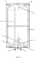
Figure 2 is a sectional view of the water heater comprising the water guide according to the invention. -
Figure 3 is top sectional view of the water heater comprising the water guide according to the invention. - All the parts illustrated in figures are individually assigned a reference numeral and the corresponding terms of these numbers are listed below:
Water tank (1) Base (1a) Roof (1b) Side wall (1c) Water inlet (2) Water outlet (3) Hot water pipe (4) Heating apparatus (5) Water guide (6) Inlet pipe (6a) Neck (6b) Outlet pipe (6c) First inlet opening (6d) Second outlet opening (6e) Lower part (7) Upper part (8) Flow direction (9) First angle (10) Second angle (11) Middle axis (12) Centre (13) Line (14) - Water heaters may comprise water tanks in which cold water is received, heated and stored; and a user can discharge a desired amount of hot water from the water tank. Cold water is introduced into the water tank in return for the discharged hot water. In order to use hot water stored in the water tank effectively, it is desirable that the cold water received into the water tank does not mix with the hot water contained in the water tank. However, since the water inlet located at the base of the water tank provides water flow towards the upper part of the water tank with a high flow rate, it is not possible to keep hot water at the upper part of the water tank without mixing with cold water. Within this context, according to the present invention, there is provided a water guide and a water heater comprising the water guide, which eliminates abovementioned problems.
- The water guide (6) according to the present invention, as illustrated in
Figures 1-3 , is suitable for use in a water heater which comprises at least one water tank (1) having at least one base (1a), at least one roof (1b) and at least one side wall (1c); at least one water inlet (2) located at the base (1a) of the water tank (1) and introducing cold water into the water tank (1) at a first flow rate; at least one heating apparatus (5), e.g. a resistance, for heating cold water received into the water tank (1), which is mounted to the base (1a) of the water tank (1); and at least one water outlet (3) for receiving water from an upper part (8) of the water tank (1) close to the roof (1b) thereof so that the water is discharged, wherein the water guide (6) comprises at least one inlet pipe (6a) comprising at least a first inlet opening (6d) and at least a first outlet opening (not illustrated in the figures), and suitable for being connected to the water inlet (2) through the first inlet opening (6d) so as to extend perpendicularly from the base (1a) towards the inner side of the water tank (1), wherein diameters of the first inlet opening (6d) and the first outlet opening are equal to each other; at least one outlet pipe (6c) comprising a second inlet opening (not illustrated in the figures) and a second outlet opening (6e), wherein diameter of the second outlet opening (6e) is higher than the second inlet opening and thus the outlet pipe (6c) enables the water introduced through the second inlet opening and passing through the outlet pipe (6c) to exit through the second outlet opening (6e) such that its flow rate is reduced; and at least one neck (6b) which connects the first outlet opening and second inlet opening to each other such that a first angle (10) less than 90° is provided between the inlet pipe (6a) and the outlet pipe (6c), and thus, enables the water from the water inlet (2) to be directed to the base (1a) of the water tank (1) at a second flow rate lower than first flow rate. - In an exemplary embodiment of the invention, the water heater heats the cold water, which is received from the water inlet (2) located at the base (1a) of the water tank (1), by means of the heating apparatus (5). Heated water moves upward such that there is water at a ready-to-use temperature in the upper part (8) of the water tank (1) while the relatively cold water is contained in the lower part (7) of the water tank (1). The water outlet (3) provides water discharge from the upper part (8) of the water tank (1) close to the roof (1b), so that the hot water contained in the water tank (1) can be discharged by the user. Here, the lower part (7) close to the base may be defined as the area between a middle part and the base (1a) of the water tank (1) or the area up to a few centimetres above the base (1a) or the area up to a maximum of 30 centimetres above the base (1a), depending on dimensions of the water tank (1). Likewise, the upper part (8) of the water tank (1) close to the roof (1b) may be defined as the area between a middle part and the roof (1b) of the water tank (1) or the area up to a few centimetres below the roof (1 b) or the area up to a maximum of 30 centimetres below the roof (1b), depending on dimensions of the water tank (1). The water guide (6) is connected to the water inlet (2), which is located at the base (1a) of the water tank (1), through the first inlet opening (6d). The water inlet (2) may be, for example, an opening or a pipe that is connected to a water supply line and enables mains water to be introduced into the water tank (1). The water coming from the water inlet (2) at a first flow rate is introduced into the inlet pipe (6a) through the first inlet opening (6d). The inlet pipe (6a) has a cylindrical form and is connected to the water inlet (2) so as to extend perpendicularly to the inner side of the water tank (1). After moving through the inlet pipe (6a), the water then passes through the first outlet opening into the neck (6b), where the direction of the water changes and thus the water introduced into the water tank (1) in the vertical direction is directed towards the base (1a). Water leaving the neck (6b) then reaches the outlet pipe (6c) by passing through the second inlet opening. The outlet pipe (6c) has a conical structure and a widening diameter, so that a flow rate of water introduced through the second inlet opening is reduced and the water exits through the second outlet opening (6e) at a second flow rate lower than the first flow rate such that it moves towards the base (1a) as a single water passage. By reducing the flow rate of water and directing it as a single water passage towards the base (1a) of the water tank, it is ensured that the hot water contained in the water tank (1) and the cold water introduced into the water tank (1) do not mix with each other or mix at a minimum level.
- In a preferred embodiment of the invention, the diameter of the first outlet opening is equal to the diameter of the second inlet opening. In said embodiment, the water passing through the neck (6b) is directed without changing its flow rate. In a preferred embodiment of the invention, the neck (6b) and the outlet pipe (6c) are integral. In said embodiment, the integral part comprising the neck (6b) and the outlet pipe (6c) is connected to the first outlet opening of the inlet pipe (6a). In another preferred embodiment of the invention, the water inlet pipe (6a) and the neck (6b) are integral; and in said embodiment, the outlet pipe (6c) is connected to the outlet of the integral part which is connected to the water inlet (2) through the first inlet opening (6d) and comprises the water inlet pipe (6a) and the neck (6b). Yet in another preferred embodiment of the invention, the inlet pipe (6a), the neck (6b) and the outlet pipe (6c) are integral.
- According to the present invention, there is also provided a water heater comprising the water guide (6). A preferred embodiment of the invention is illustrated in
Figure 3 ; and in said embodiment, the side wall (1c) has a cylindrical structure and the water guide (6) is mounted to the water inlet (2) such that the water exiting through the second outlet opening (6e) is directed parallel to the side wall (1c). Therefore, the cold water is enabled to move in a circular flow direction (9) and parallel to the side wall (1c), so that it is prevented from moving upwards. In said embodiment, there is a second angle (11) higher than 45° and lower than 90° between a middle axis (12) of the outlet pipe (6c) and a line (14) extending from the centre (13) of the water tank towards the water inlet (2). In another preferred embodiment of the invention, the heating apparatus (5) is located at the centre (13) of the base (1a), so that the cold water is enabled to move circularly around the heating apparatus (5). - In a preferred embodiment of the invention, the water outlet (3) may be located at an upper part (8) of the water tank (1) close the roof (1b) thereof or at the roof (1b) thereof, so that the hot water contained at the upper part (8) of the water tank (1) is discharged. In another preferred embodiment of the invention, the water outlet (3) may be located at the base (1a) of the water tank (1) or at the lower part (7) thereof close to the base (1a), in which case at least one hot water pipe (4) enables the hot water contained in the upper part (8) of the water tank (1) to be delivered to the water outlet (3) such that it is discharged by the user if desired, wherein one end of the hot water pipe (4) is connected to the water outlet (3) and another end thereof communicates into the upper part (8) of the water tank (1) close to the roof (1b).
- The water guide (6) of the present invention slows down the outlet speed of the water thanks to the outlet pipe (6c) having a widening diameter, and directs the cold water towards the base (1a) of the water tank (1) such that it is directed parallel to the side wall (1c) and with a single flow passage, thanks to the neck (6b). Therefore, it is enabled that hot water contained in the water tank (1) and the cold water received into the water tank (1) are separate from each other and do not mix with each other.
Claims (9)
- A water guide (6) suitable for use in a water heater which comprises at least one water tank (1) having at least one base (1a), at least one roof (1b) and at least one side wall (1c); at least one water inlet (2) located at the base (1a) of the water tank (1) and introducing cold water into the water tank (1) at a first flow rate; at least one heating apparatus (5) for heating cold water received into the water tank (1), which is mounted to the base (1a) of the water tank (1); and at least one water outlet (3) for receiving water from an upper part (8) of the water tank (1) close to the roof (1b) thereof so that the water is discharged, characterized by comprising at least one inlet pipe (6a) comprising at least a first inlet opening (6d) and at least a first outlet opening whose diameters are equal to each other, and suitable for being connected to the water inlet (2) through the first inlet opening (6d) so as to extend perpendicularly from the base (1a) towards the inner side of the water tank (1); at least one outlet pipe (6c) comprising a second inlet opening and a second outlet opening (6e) whose diameter is higher than the second inlet opening, and thus enabling the flow rate of water passing through the outlet pipe (6c) to be reduced; and at least one neck (6b) which connects the first outlet opening and second inlet opening to each other such that a first angle (10) less than 90° is provided between the inlet pipe (6a) and the outlet pipe (6c), and thus, enables the water from the water inlet (2) to be directed to the base (1a) of the water tank (1) at a second flow rate lower than first flow rate.
- A water guide according to claim 1, characterized in that the diameter of the first outlet opening and the diameter of the second inlet opening are equal to each other.
- A water guide (6) according to claim 1, characterized in that the neck (6b) and the outlet pipe (6c) are integral.
- A water guide (6) according to claim 1, characterized in that the water inlet pipe (6a) and the neck (6b) are integral.
- A water guide (6) according to claim 1, characterized in that the inlet pipe (6a), the neck (6b) and the outlet pipe (6c) are integral.
- A water heater comprising a water guide (6) according to any of the preceding claims.
- A water heater according to claim 6, characterized in that the side wall (1c) has a cylindrical structure and the water guide (6) is mounted to the water inlet (2) such that the water exiting through the second outlet opening (6e) is directed parallel to the side wall (1c).
- A water heater according any of the claims 6 or 7, characterized in that the heating apparatus (5) is located at the centre (13) of the base (1a).
- A water heater according to any of the claims 6 to 8, characterized by comprising at least one hot water pipe (4), one end of which is connected to the water outlet (3) and another end of which communicates into the upper part (8) of the water tank (1) close to the roof (1b).
Applications Claiming Priority (1)
| Application Number | Priority Date | Filing Date | Title |
|---|---|---|---|
| TR2019/14500A TR201914500A2 (en) | 2019-09-24 | 2019-09-24 | A kettle comprising a water diverter and said water diverter. |
Publications (2)
| Publication Number | Publication Date |
|---|---|
| EP3798531A1 true EP3798531A1 (en) | 2021-03-31 |
| EP3798531B1 EP3798531B1 (en) | 2023-10-18 |
Family
ID=72708983
Family Applications (1)
| Application Number | Title | Priority Date | Filing Date |
|---|---|---|---|
| EP20196211.5A Active EP3798531B1 (en) | 2019-09-24 | 2020-09-15 | Water heater comprising a water guide |
Country Status (2)
| Country | Link |
|---|---|
| EP (1) | EP3798531B1 (en) |
| TR (1) | TR201914500A2 (en) |
Citations (4)
| Publication number | Priority date | Publication date | Assignee | Title |
|---|---|---|---|---|
| DE9200824U1 (en) * | 1992-01-24 | 1992-03-12 | Terbrack, Erich, 4441 Wettringen, De | |
| DE4301725A1 (en) * | 1992-01-24 | 1993-09-09 | Solar Diamant Syst | Cold water supply for upright thermosyphonic stratified storage cylinder - enters upper cylinder at right angles and is then bent down and outwards with second horizontal and inwards bed at lower end |
| DE19754586A1 (en) * | 1997-12-09 | 1998-07-09 | Harald Trillitzsch | Backflow lifting automatic for hot water boiler |
| WO2019110996A1 (en) * | 2017-12-08 | 2019-06-13 | Mixergy Limited | A hot water storage tank and a diffuser |
-
2019
- 2019-09-24 TR TR2019/14500A patent/TR201914500A2/en unknown
-
2020
- 2020-09-15 EP EP20196211.5A patent/EP3798531B1/en active Active
Patent Citations (4)
| Publication number | Priority date | Publication date | Assignee | Title |
|---|---|---|---|---|
| DE9200824U1 (en) * | 1992-01-24 | 1992-03-12 | Terbrack, Erich, 4441 Wettringen, De | |
| DE4301725A1 (en) * | 1992-01-24 | 1993-09-09 | Solar Diamant Syst | Cold water supply for upright thermosyphonic stratified storage cylinder - enters upper cylinder at right angles and is then bent down and outwards with second horizontal and inwards bed at lower end |
| DE19754586A1 (en) * | 1997-12-09 | 1998-07-09 | Harald Trillitzsch | Backflow lifting automatic for hot water boiler |
| WO2019110996A1 (en) * | 2017-12-08 | 2019-06-13 | Mixergy Limited | A hot water storage tank and a diffuser |
Also Published As
| Publication number | Publication date |
|---|---|
| TR201914500A2 (en) | 2021-04-21 |
| EP3798531B1 (en) | 2023-10-18 |
Similar Documents
| Publication | Publication Date | Title |
|---|---|---|
| US6161469A (en) | Espresso machine | |
| US9668452B2 (en) | Device for production of dairy products, especially milk foam | |
| US6526872B2 (en) | Coffee making machine | |
| US7634976B2 (en) | Apparatus and method for delivering water into a water heater | |
| CN106488727B (en) | Instant tube heater with uniform temperature control | |
| US20110072977A1 (en) | Coffee/espresso machine comprising a milk foam generating device for cappuccino | |
| CN109952049A (en) | Beverage maker including mixing chamber | |
| PL191076B1 (en) | Vessel and wort processing method for producing beer | |
| US9134037B2 (en) | Equipment for producing domestic hot water | |
| CN110312452B (en) | Device for heating milk or milk foam | |
| CN110446445A (en) | It is used to prepare the brewing device and correlation technique of hot drink | |
| EP3798531A1 (en) | A water guide and a water heater comprising the water guide | |
| CN102036590B (en) | Device, component and method for admixing a fluid to a beverage | |
| CA2521319C (en) | Method and device for brewing beer | |
| US2265108A (en) | Controlled circulation water heating system | |
| CN103237481B (en) | With the home appliance for the preparation of the beverage based on hot water of twin containers | |
| EP0727167A1 (en) | Steam nozzle for espresso machines | |
| US3581057A (en) | Hot water heater | |
| EP2848874A1 (en) | Water heating apparatus | |
| DE10033910B4 (en) | stratified storage | |
| US20050118047A1 (en) | Device for dispensing water in portions | |
| CN108291181A (en) | One kind wheat juice heat-treating methods and container in Beer Brewage or beverage production | |
| CN210184234U (en) | A discharging pipe and fodder scattering ware for fodder scattering ware | |
| CH698188B1 (en) | Apparatus for heating and frothing liquids. | |
| JP6593775B2 (en) | Instant hot water system |
Legal Events
| Date | Code | Title | Description |
|---|---|---|---|
| PUAI | Public reference made under article 153(3) epc to a published international application that has entered the european phase |
Free format text: ORIGINAL CODE: 0009012 |
|
| STAA | Information on the status of an ep patent application or granted ep patent |
Free format text: STATUS: THE APPLICATION HAS BEEN PUBLISHED |
|
| AK | Designated contracting states |
Kind code of ref document: A1 Designated state(s): AL AT BE BG CH CY CZ DE DK EE ES FI FR GB GR HR HU IE IS IT LI LT LU LV MC MK MT NL NO PL PT RO RS SE SI SK SM TR |
|
| AX | Request for extension of the european patent |
Extension state: BA ME |
|
| STAA | Information on the status of an ep patent application or granted ep patent |
Free format text: STATUS: REQUEST FOR EXAMINATION WAS MADE |
|
| 17P | Request for examination filed |
Effective date: 20210923 |
|
| RBV | Designated contracting states (corrected) |
Designated state(s): AL AT BE BG CH CY CZ DE DK EE ES FI FR GB GR HR HU IE IS IT LI LT LU LV MC MK MT NL NO PL PT RO RS SE SI SK SM TR |
|
| REG | Reference to a national code |
Ref country code: DE Ref legal event code: R079 Ref document number: 602020019361 Country of ref document: DE Free format text: PREVIOUS MAIN CLASS: F24H0009120000 Ipc: F24H0009130000 Ref country code: DE Ref legal event code: R079 Free format text: PREVIOUS MAIN CLASS: F24H0009120000 Ipc: F24H0009130000 |
|
| GRAP | Despatch of communication of intention to grant a patent |
Free format text: ORIGINAL CODE: EPIDOSNIGR1 |
|
| STAA | Information on the status of an ep patent application or granted ep patent |
Free format text: STATUS: GRANT OF PATENT IS INTENDED |
|
| RIC1 | Information provided on ipc code assigned before grant |
Ipc: F28D 20/00 20060101ALI20230425BHEP Ipc: F24H 9/13 20220101AFI20230425BHEP |
|
| INTG | Intention to grant announced |
Effective date: 20230515 |
|
| GRAS | Grant fee paid |
Free format text: ORIGINAL CODE: EPIDOSNIGR3 |
|
| GRAA | (expected) grant |
Free format text: ORIGINAL CODE: 0009210 |
|
| STAA | Information on the status of an ep patent application or granted ep patent |
Free format text: STATUS: THE PATENT HAS BEEN GRANTED |
|
| AK | Designated contracting states |
Kind code of ref document: B1 Designated state(s): AL AT BE BG CH CY CZ DE DK EE ES FI FR GB GR HR HU IE IS IT LI LT LU LV MC MK MT NL NO PL PT RO RS SE SI SK SM TR |
|
| REG | Reference to a national code |
Ref country code: GB Ref legal event code: FG4D |
|
| REG | Reference to a national code |
Ref country code: CH Ref legal event code: EP |
|
| REG | Reference to a national code |
Ref country code: IE Ref legal event code: FG4D |
|
| REG | Reference to a national code |
Ref country code: DE Ref legal event code: R096 Ref document number: 602020019361 Country of ref document: DE |
|
| REG | Reference to a national code |
Ref country code: LT Ref legal event code: MG9D |
|
| REG | Reference to a national code |
Ref country code: NL Ref legal event code: MP Effective date: 20231018 |
|
| REG | Reference to a national code |
Ref country code: AT Ref legal event code: MK05 Ref document number: 1622786 Country of ref document: AT Kind code of ref document: T Effective date: 20231018 |
|
| PG25 | Lapsed in a contracting state [announced via postgrant information from national office to epo] |
Ref country code: NL Free format text: LAPSE BECAUSE OF FAILURE TO SUBMIT A TRANSLATION OF THE DESCRIPTION OR TO PAY THE FEE WITHIN THE PRESCRIBED TIME-LIMIT Effective date: 20231018 |
|
| PG25 | Lapsed in a contracting state [announced via postgrant information from national office to epo] |
Ref country code: GR Free format text: LAPSE BECAUSE OF FAILURE TO SUBMIT A TRANSLATION OF THE DESCRIPTION OR TO PAY THE FEE WITHIN THE PRESCRIBED TIME-LIMIT Effective date: 20240119 |
|
| PG25 | Lapsed in a contracting state [announced via postgrant information from national office to epo] |
Ref country code: IS Free format text: LAPSE BECAUSE OF FAILURE TO SUBMIT A TRANSLATION OF THE DESCRIPTION OR TO PAY THE FEE WITHIN THE PRESCRIBED TIME-LIMIT Effective date: 20240218 |
|
| PG25 | Lapsed in a contracting state [announced via postgrant information from national office to epo] |
Ref country code: LT Free format text: LAPSE BECAUSE OF FAILURE TO SUBMIT A TRANSLATION OF THE DESCRIPTION OR TO PAY THE FEE WITHIN THE PRESCRIBED TIME-LIMIT Effective date: 20231018 |