EP3798529A1 - Indicator generating method and predictive maintenance method for failure prediction for a water heating system, such water heating system, and beverage maker - Google Patents
Indicator generating method and predictive maintenance method for failure prediction for a water heating system, such water heating system, and beverage maker Download PDFInfo
- Publication number
- EP3798529A1 EP3798529A1 EP19210271.3A EP19210271A EP3798529A1 EP 3798529 A1 EP3798529 A1 EP 3798529A1 EP 19210271 A EP19210271 A EP 19210271A EP 3798529 A1 EP3798529 A1 EP 3798529A1
- Authority
- EP
- European Patent Office
- Prior art keywords
- water
- indicator
- reheating
- power consumption
- heating system
- Prior art date
- Legal status (The legal status is an assumption and is not a legal conclusion. Google has not performed a legal analysis and makes no representation as to the accuracy of the status listed.)
- Granted
Links
Images


Classifications
-
- F—MECHANICAL ENGINEERING; LIGHTING; HEATING; WEAPONS; BLASTING
- F24—HEATING; RANGES; VENTILATING
- F24H—FLUID HEATERS, e.g. WATER OR AIR HEATERS, HAVING HEAT-GENERATING MEANS, e.g. HEAT PUMPS, IN GENERAL
- F24H9/00—Details
- F24H9/20—Arrangement or mounting of control or safety devices
- F24H9/2007—Arrangement or mounting of control or safety devices for water heaters
- F24H9/2014—Arrangement or mounting of control or safety devices for water heaters using electrical energy supply
- F24H9/2021—Storage heaters
-
- F—MECHANICAL ENGINEERING; LIGHTING; HEATING; WEAPONS; BLASTING
- F24—HEATING; RANGES; VENTILATING
- F24H—FLUID HEATERS, e.g. WATER OR AIR HEATERS, HAVING HEAT-GENERATING MEANS, e.g. HEAT PUMPS, IN GENERAL
- F24H1/00—Water heaters, e.g. boilers, continuous-flow heaters or water-storage heaters
-
- A—HUMAN NECESSITIES
- A47—FURNITURE; DOMESTIC ARTICLES OR APPLIANCES; COFFEE MILLS; SPICE MILLS; SUCTION CLEANERS IN GENERAL
- A47J—KITCHEN EQUIPMENT; COFFEE MILLS; SPICE MILLS; APPARATUS FOR MAKING BEVERAGES
- A47J31/00—Apparatus for making beverages
- A47J31/44—Parts or details or accessories of beverage-making apparatus
- A47J31/60—Cleaning devices
-
- F—MECHANICAL ENGINEERING; LIGHTING; HEATING; WEAPONS; BLASTING
- F24—HEATING; RANGES; VENTILATING
- F24H—FLUID HEATERS, e.g. WATER OR AIR HEATERS, HAVING HEAT-GENERATING MEANS, e.g. HEAT PUMPS, IN GENERAL
- F24H15/00—Control of fluid heaters
- F24H15/10—Control of fluid heaters characterised by the purpose of the control
- F24H15/104—Inspection; Diagnosis; Trial operation
-
- F—MECHANICAL ENGINEERING; LIGHTING; HEATING; WEAPONS; BLASTING
- F24—HEATING; RANGES; VENTILATING
- F24H—FLUID HEATERS, e.g. WATER OR AIR HEATERS, HAVING HEAT-GENERATING MEANS, e.g. HEAT PUMPS, IN GENERAL
- F24H15/00—Control of fluid heaters
- F24H15/10—Control of fluid heaters characterised by the purpose of the control
- F24H15/144—Measuring or calculating energy consumption
- F24H15/148—Assessing the current energy consumption
-
- F—MECHANICAL ENGINEERING; LIGHTING; HEATING; WEAPONS; BLASTING
- F24—HEATING; RANGES; VENTILATING
- F24H—FLUID HEATERS, e.g. WATER OR AIR HEATERS, HAVING HEAT-GENERATING MEANS, e.g. HEAT PUMPS, IN GENERAL
- F24H15/00—Control of fluid heaters
- F24H15/20—Control of fluid heaters characterised by control inputs
-
- F—MECHANICAL ENGINEERING; LIGHTING; HEATING; WEAPONS; BLASTING
- F24—HEATING; RANGES; VENTILATING
- F24H—FLUID HEATERS, e.g. WATER OR AIR HEATERS, HAVING HEAT-GENERATING MEANS, e.g. HEAT PUMPS, IN GENERAL
- F24H15/00—Control of fluid heaters
- F24H15/20—Control of fluid heaters characterised by control inputs
- F24H15/212—Temperature of the water
- F24H15/223—Temperature of the water in the water storage tank
-
- F—MECHANICAL ENGINEERING; LIGHTING; HEATING; WEAPONS; BLASTING
- F24—HEATING; RANGES; VENTILATING
- F24H—FLUID HEATERS, e.g. WATER OR AIR HEATERS, HAVING HEAT-GENERATING MEANS, e.g. HEAT PUMPS, IN GENERAL
- F24H15/00—Control of fluid heaters
- F24H15/20—Control of fluid heaters characterised by control inputs
- F24H15/238—Flow rate
-
- F—MECHANICAL ENGINEERING; LIGHTING; HEATING; WEAPONS; BLASTING
- F24—HEATING; RANGES; VENTILATING
- F24H—FLUID HEATERS, e.g. WATER OR AIR HEATERS, HAVING HEAT-GENERATING MEANS, e.g. HEAT PUMPS, IN GENERAL
- F24H15/00—Control of fluid heaters
- F24H15/20—Control of fluid heaters characterised by control inputs
- F24H15/254—Room temperature
-
- F—MECHANICAL ENGINEERING; LIGHTING; HEATING; WEAPONS; BLASTING
- F24—HEATING; RANGES; VENTILATING
- F24H—FLUID HEATERS, e.g. WATER OR AIR HEATERS, HAVING HEAT-GENERATING MEANS, e.g. HEAT PUMPS, IN GENERAL
- F24H15/00—Control of fluid heaters
- F24H15/20—Control of fluid heaters characterised by control inputs
- F24H15/269—Time, e.g. hour or date
-
- F—MECHANICAL ENGINEERING; LIGHTING; HEATING; WEAPONS; BLASTING
- F24—HEATING; RANGES; VENTILATING
- F24H—FLUID HEATERS, e.g. WATER OR AIR HEATERS, HAVING HEAT-GENERATING MEANS, e.g. HEAT PUMPS, IN GENERAL
- F24H15/00—Control of fluid heaters
- F24H15/30—Control of fluid heaters characterised by control outputs; characterised by the components to be controlled
- F24H15/305—Control of valves
- F24H15/31—Control of valves of valves having only one inlet port and one outlet port, e.g. flow rate regulating valves
-
- F—MECHANICAL ENGINEERING; LIGHTING; HEATING; WEAPONS; BLASTING
- F24—HEATING; RANGES; VENTILATING
- F24H—FLUID HEATERS, e.g. WATER OR AIR HEATERS, HAVING HEAT-GENERATING MEANS, e.g. HEAT PUMPS, IN GENERAL
- F24H15/00—Control of fluid heaters
- F24H15/30—Control of fluid heaters characterised by control outputs; characterised by the components to be controlled
- F24H15/355—Control of heat-generating means in heaters
- F24H15/37—Control of heat-generating means in heaters of electric heaters
-
- F—MECHANICAL ENGINEERING; LIGHTING; HEATING; WEAPONS; BLASTING
- F24—HEATING; RANGES; VENTILATING
- F24H—FLUID HEATERS, e.g. WATER OR AIR HEATERS, HAVING HEAT-GENERATING MEANS, e.g. HEAT PUMPS, IN GENERAL
- F24H15/00—Control of fluid heaters
- F24H15/30—Control of fluid heaters characterised by control outputs; characterised by the components to be controlled
- F24H15/395—Information to users, e.g. alarms
-
- F—MECHANICAL ENGINEERING; LIGHTING; HEATING; WEAPONS; BLASTING
- F24—HEATING; RANGES; VENTILATING
- F24H—FLUID HEATERS, e.g. WATER OR AIR HEATERS, HAVING HEAT-GENERATING MEANS, e.g. HEAT PUMPS, IN GENERAL
- F24H15/00—Control of fluid heaters
- F24H15/40—Control of fluid heaters characterised by the type of controllers
- F24H15/414—Control of fluid heaters characterised by the type of controllers using electronic processing, e.g. computer-based
-
- F—MECHANICAL ENGINEERING; LIGHTING; HEATING; WEAPONS; BLASTING
- F24—HEATING; RANGES; VENTILATING
- F24H—FLUID HEATERS, e.g. WATER OR AIR HEATERS, HAVING HEAT-GENERATING MEANS, e.g. HEAT PUMPS, IN GENERAL
- F24H15/00—Control of fluid heaters
- F24H15/40—Control of fluid heaters characterised by the type of controllers
- F24H15/414—Control of fluid heaters characterised by the type of controllers using electronic processing, e.g. computer-based
- F24H15/45—Control of fluid heaters characterised by the type of controllers using electronic processing, e.g. computer-based remotely accessible
-
- G—PHYSICS
- G01—MEASURING; TESTING
- G01K—MEASURING TEMPERATURE; MEASURING QUANTITY OF HEAT; THERMALLY-SENSITIVE ELEMENTS NOT OTHERWISE PROVIDED FOR
- G01K13/00—Thermometers specially adapted for specific purposes
-
- G—PHYSICS
- G01—MEASURING; TESTING
- G01M—TESTING STATIC OR DYNAMIC BALANCE OF MACHINES OR STRUCTURES; TESTING OF STRUCTURES OR APPARATUS, NOT OTHERWISE PROVIDED FOR
- G01M99/00—Subject matter not provided for in other groups of this subclass
- G01M99/005—Testing of complete machines, e.g. washing-machines or mobile phones
-
- G—PHYSICS
- G01—MEASURING; TESTING
- G01R—MEASURING ELECTRIC VARIABLES; MEASURING MAGNETIC VARIABLES
- G01R21/00—Arrangements for measuring electric power or power factor
-
- F—MECHANICAL ENGINEERING; LIGHTING; HEATING; WEAPONS; BLASTING
- F24—HEATING; RANGES; VENTILATING
- F24H—FLUID HEATERS, e.g. WATER OR AIR HEATERS, HAVING HEAT-GENERATING MEANS, e.g. HEAT PUMPS, IN GENERAL
- F24H15/00—Control of fluid heaters
- F24H15/10—Control of fluid heaters characterised by the purpose of the control
- F24H15/12—Preventing or detecting fluid leakage
-
- G—PHYSICS
- G01—MEASURING; TESTING
- G01F—MEASURING VOLUME, VOLUME FLOW, MASS FLOW OR LIQUID LEVEL; METERING BY VOLUME
- G01F1/00—Measuring the volume flow or mass flow of fluid or fluent solid material wherein the fluid passes through a meter in a continuous flow
Definitions
- the invention relates to a method and device for generating an indicator which is suitable for maintenance prediction of a water heating system. Furthermore the invention relates to a water heating system e.g. beverage maker.
- US 2011 / 0 095 010 A1 discloses a water heating system with a resistive heating element.
- a control is connected for monitoring a resistance parameter of the resistive heating element, wherein the control is configured to output a fault signal if the monitored resistance parameter exceeds a set threshold.
- the invention provides an indicator generating method for generating an indicator which is suitable for maintenance prediction of a water heating system, the water heating system comprising a water tank containing water to be heated by a heating device, a power state indication device and a monitoring device, the method comprising:
- the power state indication device includes a power measurement device which measures the power consumption of the heating device and generates the high power consumption signal, if the power consumption exceeds a predetermined high power threshold, and/or generates the low power consumption signal, if the power consumption drops below a predetermined low power threshold.
- the high power threshold and the low power threshold are set to be equal.
- the power state indicator device includes a communication interface which outputs the current water heating system state to an inter-device communications network, from which the monitoring device is able to obtain the water heating system state.
- the monitoring device determines a reheating time, which is the time duration of the high power consumption signal, and outputs the reheating time as a condition-based degradation indicator.
- the time duration is determined by certain states of the water heating system.
- the monitoring device determines a condition-based degradation indicator also based on the time interval between two subsequent high power consumption signals.
- the monitoring device determines the presence of a reheating cycle at least based on the time interval between two subsequent high power consumption signals.
- the monitoring device determines a reheating frequency, which is the time interval between two subsequent high power consumption signals, and additionally outputs reheating frequency as a condition-based degradation indicator.
- the water heating system comprises one or more additional sensors, which measure additional physical quantities, and the monitoring device additionally processes the measured quantities for generating the indicator.
- the water heating system comprises an ambient temperature sensor, which measures the ambient temperature, and the monitoring device additionally processes the measured ambient temperature for generating the indicator.
- the water heating system comprises a water quality sensor for obtaining a water quality, the water quality sensor being configured for measuring physical parameters indicative of the specific heat capacity, and the monitoring device additionally processes the obtained water quality for generating the indicator.
- the water quality sensor is configured for measuring total dissolved solids in water.
- the monitoring device determines a usage-based indicator based on sensor data and/or state information available on an inter-device communications network.
- the usage-based indicator includes the number of operation cycles, heating times, water quality, and/or water flows.
- the water heating system comprises a water flow sensor, which measures the presence of water flow to or from the tank, and the monitoring device discards the high power consumption signal input, preferably as a reheating cycle, if the water flow sensor detects presence of a water flow, and/or the monitoring device additionally outputs the water flow sensor data as a usage-based indicator.
- the water heating system comprises a water quality sensor, which measures the quality of the water and the monitoring device corrects the reheating times and/or reheating frequency based on the specific heat capacity, and/or the monitoring device additionally outputs the water quality sensor data as a usage-based indicator.
- a water quality sensor which measures the quality of the water and the monitoring device corrects the reheating times and/or reheating frequency based on the specific heat capacity, and/or the monitoring device additionally outputs the water quality sensor data as a usage-based indicator.
- the water quality sensor comprises a total dissolved solids sensors (TDS sensor).
- TDS sensor total dissolved solids sensors
- the invention provides a predictive maintenance method for generating a maintenance signal, which indicates that a water heating system monitored by a predictive maintenance device requires maintenance, the water heating system comprising a water tank containing water to be heated by a heating device, a power state indication device and a monitoring device, the method comprising:
- condition-based degradation indicator includes a reheating time
- the predictive maintenance device determines the remaining useful lifetime such that the remaining useful lifetime decreases, if the reheating time increases.
- condition-based degradation indicator includes a reheating frequency
- the predictive maintenance device determines the remaining useful lifetime such that the remaining useful lifetime decreases, if the reheating frequency increases.
- condition-based degradation indicator includes an ambient temperature and/or water quality
- the predictive maintenance device determines the remaining useful lifetime such that the remaining useful lifetime decreases, if the predictive maintenance device determines that the reheating time is larger than and/or the reheating frequency is higher than an expected value for the reheating time and/or reheating frequency, wherein preferably the expected value is determined based on the ambient temperature and/or water quality.
- the invention provides a water heating system for a beverage maker of an aircraft galley, the water heating system configured for heating water and comprising a water tank suitable to hold water to be heated, a heating device configured for heating the water within the water tank, a power state indication device configured for generating at least a low power consumption signal or a high power consumption signal based on the power consumption of the heating device; and a monitoring device configured for performing a preferred indicator generating method or a preferred predictive maintenance method.
- the invention provides a beverage maker, in particular coffee maker or tea maker, for an aircraft galley comprising a preferred water heating system.
- the invention provides a data medium containing instructions for a computer system, which, when executed by the computer system, perform a preferred method according to the invention.
- the idea is in the field of predictive maintenance for heated water tank equipment, especially beverage makers in aircraft galleys.
- the invention may allow for improved (i.e. minimized) observability requirements and technical solution for their implementation.
- Results of the measures may be offered as a digital service in a predictive maintenance framework and/or for maintenance services of flight hour services in order to allow prediction improved spares ability.
- An approach to observe a heating system degradation of a water tank includes measuring input tank temperatures, water flow, and electrical power.
- the invention is based on the idea that these observability requirements may be reduced to a few features that can be approximately derived from a single sensor, e.g. a power sensor.
- the invention may avoid the installation of additional sensors, take into account available data from modern aircraft communication protocols such as ARINC 812, and allow application to aircraft already in service.
- the focus here are beverage makers for aircraft galleys. It should be noted that the invention may be applicable to other devices having water heating systems with a closed tank that is kept at a certain temperature.
- the invention may derive degradation patterns from evaluation of a minimum set of measured data.
- a minimized set of features is used for predictive maintenance of e.g. beverage makers.
- This preferably includes condition-based indicators describing the actual condition of the equipment and/or usage-based indicators which may be correlated with equipment condition. These indicators may be derived from existing data for smart devices and/or a single sensor for legacy devices.
- the "reheating time” feature describes the time duration it regularly takes to keep the water in the equipment tank within a temperature range.
- the temperature range can be predetermined by an upper and a lower threshold without in- and outflow of water (i.e. no mixing problem).
- This features usually shows an increasing trend covering degradations typically caused by limescale, heater degradation, thermostat degradation, etc.
- ⁇ heater c ⁇ m ⁇ ⁇ T + Q flow + Q dissipation
- P heater_nominal ⁇ t c ⁇ m ⁇ ⁇ T P heater_nominal ⁇ 1 t reheating
- ⁇ heater C heated_tank ⁇ 1 t reheating wherein C heated_tank is an equipment specific constant.
- the invention allows to observe a degrading heat efficiency if a relative increase in time for which the heater is turned on during reheating cycles is measured. Thus the "reheating time" is measured.
- the reheating frequency describes the time between two consecutive reheating cycles and is determined by the heat loss from the temperature set point to the lower threshold when the next reheating cycle starts.
- This heat loss is nominally caused by the temperature drop between the hot water within the tank and the lower ambient temperature and covers failure cases like a degrading tank insulation or hot water leakage.
- Usage-based indicators may be correlated to other failure types. Usage-based indicators include operating cycles, heating times and water flows to be cumulated.
- the method according to the invention requires at least the duration of the reheating time as input.
- two main categories of beverage maker are distinguished: legacy equipment without a communication interface and "smart" equipment implementing e.g. the ARINC 812 standard.
- Smart beverage makers may be ARINC 812 enabled, for example.
- the ARINC 812 standard defines a STATE_MESSAGE whereby e.g. a beverage maker can communicate their state, and especially requests to a power management function for a certain power budget for a certain time. This time is decremented every second from a certain starting value in a REMAINING_TIME field.
- the reheating cycles can be identified by any of their regular occurrence, the relatively short power request duration (such as 60 seconds), and the relatively short actual heating duration (about 10 seconds). Further parameters will ease and improve the feature extraction. Thus, those embodiments are preferred. They may include water flow values, ambient temperature, and water quality.
- the invention for this part thus may include technical means for feature extraction based on ARINC 812 data, especially power request budgets and timers.
- Legacy beverage makers i.e. older beverage maker types, do not include a communication interface.
- a power measurement can be implemented upstream of the input of the beverage maker. This measurement does merely need to distinguish between normal (e.g. stand-by) and increased power consumption (heating) and their respective durations.
- Further parameters may ease and improve the feature extraction. They include water flow values, ambient temperature, and/or water quality. They can be installed as external sensors upstream of the equipment comparable to the power measurement.
- the invention thus includes technical means for feature extraction comprising of one or more retrofittable sensors, in particular upstream of the equipment without requiring an equipment modification.
- the basic principles for feature extraction is based on the availability of data such as "used power", e.g. the duration of high power inflows. Additional data e.g. the "remaining time” field in the ARINC 812 data or a flow sensor value can make the feature extraction more precise.
- a beverage maker 10 is depicted.
- the beverage maker 10 is configured for a galley of an aircraft.
- the beverage maker 10 comprises a brewing assembly 12 for preparing hot beverages 14 from hot water.
- the brewing assembly 12 may be configured for preparing coffee or tea, for example.
- the beverage maker 10 includes a water heating system 16 which is configured for heating water.
- the water heating system 16 is configured to keep the heated water within a predetermined temperature range.
- the water heating system 16 comprises a water tank 18 which is able to hold water 20 to be heated.
- the water tank 18 may have a thermal insulation so as to reduce heat dissipation from the water tank 18 to the environment.
- the water heating system 16 comprises a heating device 22.
- the heating device 22 is arranged within the water tank 18 so as to be able to heat the water 20.
- the water heating system 16 comprises a thermal sensor 24 for measuring the temperature of the water 20.
- the thermal sensor 24 can be integrated into the heating device 22. It is also possible that the thermal sensor 24 is configured separately or integrated in another suitable component of the water heating system 16.
- the water heating system 16 includes an inlet valve 26 which controls the inlet of fresh water into the water tank 18. Furthermore, the water heating system 16 includes an outlet valve 28 which controls the outlet of hot water to the brewing assembly 12.
- the water heating system 16 comprises one or more additional sensors 30.
- the additional sensor 30 may be select from a group containing ambient temperature sensors, water flow sensors, and water quality sensors.
- the water quality sensors may be configured for obtaining a water quality, by measuring physical parameters of the water 30, the physical parameters being indicative of the specific heat capacityof the water 30.
- the water quality sensor may be a TDS Sensor which measures the amount of total dissolved solids in the water 30.
- Two additional sensors 30 may be water flow sensors arranged close to or integrated in the inlet valve 26 and outlet valve 28, so as to be able to measure inflow and/or outflow.
- the water heating system 16 comprises a power supply line 32 with which the water heating system 16 is connected to a power supply 34.
- the power supply 34 is preferably provided by an aircraft on board power grid, for example.
- the water heating system 16 also includes a power state indication device 36, which is configured to generate a low power consumption signal LOPC and a high power consumption signal HIPC based on the power consumed by the water heating system 16, in particular the heating device 22.
- the power state indication device 36 comprises a power measurement device 38, such as a power clamp 40 which is suitable for measuring power consumption without direct electrical contact to the power supply line 32.
- the low power consumption signal LOPC indicates that the heating device 22 is off
- the high power consumption signal HIPC indicates that the heating device 22 is active and heating the water 20.
- the water heating system 16 comprises a monitoring device 42.
- the monitoring device 42 is configured to monitor the water heating system 16.
- the monitoring device 42 may be implemented as a computer or microcontroller of some sort and perform various methods described below.
- the monitoring device 42 is connected to the power measurement device 38.
- the monitoring device 42 may be configured as a separate module. Furthermore, the monitoring device 42 need not be integrated into the beverage maker 10 or the water heating system 16. It is also possible for the monitoring device 42 to be arranged at a different location within the aircraft. The monitoring device 42 may be part of the power state indication device 36.
- the water heating system 16 comprises a control device 43.
- the control device 43 is configured to control the water heating system 16 and possibly the beverage maker 10.
- the control device 43 is connected to the heating device 22 so as to switch the heating device 22 on and off to keep the water 20 within a known temperature range.
- the control device 43 is also connected to the inlet and outlet valves 26, 28 as well as the additional sensors 30.
- the monitoring device 42 and the control device 43 are presently described as being integrated into a single unit. It should be noted that the devices may be separate and not even within the vicinity of each other.
- control device 43 fills the water tank 18 via inlet valve 26 if necessary and activates the heating device 22 so as to heat the water 20.
- the control device 43 measures the water temperature of the water 20 using thermal sensor 24. If the water temperature drops below a lower threshold, the heating device 22 is activated until the water temperature exceeds an upper threshold. Thus, the water temperature is kept within a predetermined temperature range. The process between two such subsequent activations of the heating device 22 is called a reheating cycle 44.
- the time duration for which the heating device 22 is activated i.e. the high power consumption signal HIPC is active, is the reheating time 46.
- the reheating time 46 is determined by the monitoring device 42 by storing a first timestamp, when the power state indication device 36 changes from the low power consumption signal LOPC to the high power consumption signal HIPC, and a second time stamp, when the power state indication device 36 changes from the high power consumption signal HIPC to the low power consumption signal LOPC.
- the reheating time 46 is then determined by subtracting the first timestamp from the second time stamp.
- a timer may be used to measure the relevant time intervals instead of the timestamps.
- the reheating time 46 is stored as a condition-based degradation indicator for further processing. Alternatively or additionally, the reheating time 46 may be processed further directly.
- the monitoring device 42 may also determine the time interval between two subsequent reheating cycles 44. This time interval is called reheating frequency 48.
- the reheating frequency 48 is also stored as a condition-based degradation indicator for further processing. Alternatively or additionally, the reheating frequency 48 may be processed further directly.
- the water heating system 16 may also comprise a predictive maintenance device 50.
- the predictive maintenance device 50 may be formed as a single unit or by plurality of components. Furthermore, the predictive maintenance device 50 may be part of the beverage maker 10 or water heating system 16 or an external component.
- the predictive maintenance device 50 is configured to output a maintenance signal, which indicates that the water heating system 16 requires maintenance.
- the predictive maintenance device 50 may be integral with the monitoring device 42 or a separate device.
- the predictive maintenance device 50 determines an estimate remaining useful lifetime using a predictive maintenance model.
- the maintenance signal is output, if the remaining useful lifetime or the condition based indicator or the usage based indicator drops below a predetermined threshold. For example, the maintenance signal is output, if an increasing reheating time causes the remaining useful lifetime to drop below a number of hours that are smaller than the next flight segment. Furthermore, the maintenance signal may be output, if the reheating frequency drops below a predetermined reheating frequency threshold.
- the maintenance signal may also be configured to have different levels of urgency, e.g. "good for one more flight segment” and/or "out of order/maintenance required”.
- the maintenance signal may also include information about the type of expected fault, such as issues with the heating element 22 or insulation of the water tank 18 or possible leakage.
- the predictive maintenance device 50 may hence include a predictive maintenance model of the beverage maker 10 or the water heating system 16.
- Fig. 2 depicts another embodiment of a beverage maker 52 which is adapted for a modern inter-device communications network that is governed by a protocol such as ARINC 812.
- the beverage maker 52 therefore comprises a communication interface 54.
- the communication interface 54 is configured to process all kinds of state-related data communicated by the inter-device communications network.
- the beverage maker 52 more precisely the power state indication device 36, comprises a heater state communication interface 56.
- the heater state communication interface 56 outputs the state of the heating device 22 via the inter-device network. Thus no additional power measurement is necessary. Rather the heater state communication interface 56 is giving the current state (on or off) of the heating device 22.
- the monitoring device 42 may e.g. store timestamps (and/or time intervals) accordingly in order to determine the reheating time and/or reheating frequency.
- Further useful data such as the tap flow etc. may be obtained via the communication interface 54, if available.
- the features obtained by the above outlined methods can serve as an input for prediction modelling methods either individually or in combination, e.g. the reheating time and frequency. Also, a cleaning of the feature data could be done, e.g. for removal of outliers.
Landscapes
- Engineering & Computer Science (AREA)
- Physics & Mathematics (AREA)
- Mechanical Engineering (AREA)
- General Engineering & Computer Science (AREA)
- Thermal Sciences (AREA)
- Chemical & Material Sciences (AREA)
- Combustion & Propulsion (AREA)
- General Physics & Mathematics (AREA)
- Computer Hardware Design (AREA)
- Fluid Mechanics (AREA)
- Health & Medical Sciences (AREA)
- Biomedical Technology (AREA)
- Power Engineering (AREA)
- Food Science & Technology (AREA)
- Heat-Pump Type And Storage Water Heaters (AREA)
Abstract
Description
- The invention relates to a method and device for generating an indicator which is suitable for maintenance prediction of a water heating system. Furthermore the invention relates to a water heating system e.g. beverage maker.
-
US 2011 / 0 095 010 A1 discloses a water heating system with a resistive heating element. A control is connected for monitoring a resistance parameter of the resistive heating element, wherein the control is configured to output a fault signal if the monitored resistance parameter exceeds a set threshold. - It is the object of the invention to improve water heating systems with respect to maintenance.
- The object is achieved by the subject-matter of the independent claims. Advantageous embodiments are subject-matter of the dependent claims.
- The invention provides an indicator generating method for generating an indicator which is suitable for maintenance prediction of a water heating system, the water heating system comprising a water tank containing water to be heated by a heating device, a power state indication device and a monitoring device, the method comprising:
- the power state indication device generating at least a low power consumption signal or a high power consumption signal based on the power consumption of the heating device;
- the monitoring device determining a condition-based degradation indicator based on the time duration of the high power consumption signal which may be included in some water heating system state information;
- wherein the monitoring device outputs the condition-based degradation indicator for further processing in a predictive maintenance device.
- Preferably, the power state indication device includes a power measurement device which measures the power consumption of the heating device and generates the high power consumption signal, if the power consumption exceeds a predetermined high power threshold, and/or generates the low power consumption signal, if the power consumption drops below a predetermined low power threshold.
- Preferably, the high power threshold and the low power threshold are set to be equal.
- Preferably, the power state indicator device includes a communication interface which outputs the current water heating system state to an inter-device communications network, from which the monitoring device is able to obtain the water heating system state.
- Preferably, the monitoring device determines a reheating time, which is the time duration of the high power consumption signal, and outputs the reheating time as a condition-based degradation indicator.
- Preferably, the time duration is determined by certain states of the water heating system.
- Preferably, the monitoring device determines a condition-based degradation indicator also based on the time interval between two subsequent high power consumption signals.
- Preferably, the monitoring device determines the presence of a reheating cycle at least based on the time interval between two subsequent high power consumption signals.
- Preferably, the monitoring device determines a reheating frequency, which is the time interval between two subsequent high power consumption signals, and additionally outputs reheating frequency as a condition-based degradation indicator.
- Preferably, the water heating system comprises one or more additional sensors, which measure additional physical quantities, and the monitoring device additionally processes the measured quantities for generating the indicator.
- Preferably, the water heating system comprises an ambient temperature sensor, which measures the ambient temperature, and the monitoring device additionally processes the measured ambient temperature for generating the indicator.
- Preferably, the water heating system comprises a water quality sensor for obtaining a water quality, the water quality sensor being configured for measuring physical parameters indicative of the specific heat capacity, and the monitoring device additionally processes the obtained water quality for generating the indicator.
- Preferably the water quality sensor is configured for measuring total dissolved solids in water.
- Preferably, the monitoring device determines a usage-based indicator based on sensor data and/or state information available on an inter-device communications network.
- Preferably, the usage-based indicator includes the number of operation cycles, heating times, water quality, and/or water flows.
- Preferably, the water heating system comprises a water flow sensor, which measures the presence of water flow to or from the tank, and the monitoring device discards the high power consumption signal input, preferably as a reheating cycle, if the water flow sensor detects presence of a water flow, and/or the monitoring device additionally outputs the water flow sensor data as a usage-based indicator.
- Preferably, the water heating system comprises a water quality sensor, which measures the quality of the water and the monitoring device corrects the reheating times and/or reheating frequency based on the specific heat capacity, and/or the monitoring device additionally outputs the water quality sensor data as a usage-based indicator.
- Preferably, the water quality sensor comprises a total dissolved solids sensors (TDS sensor).
- The invention provides a predictive maintenance method for generating a maintenance signal, which indicates that a water heating system monitored by a predictive maintenance device requires maintenance, the water heating system comprising a water tank containing water to be heated by a heating device, a power state indication device and a monitoring device, the method comprising:
- performing a preferred indicator generating method, so as to generate at least a condition-based degradation indicator;
- the predictive maintenance device determining a remaining useful lifetime based on the indicator from the previous step;
- the predictive maintenance device outputting the maintenance signal, if the remaining useful lifetime or the condition based indicator or the usage based indicator drops below a predetermined threshold.
- Preferably, the condition-based degradation indicator includes a reheating time, and the predictive maintenance device determines the remaining useful lifetime such that the remaining useful lifetime decreases, if the reheating time increases.
- Preferably, the condition-based degradation indicator includes a reheating frequency, and the predictive maintenance device determines the remaining useful lifetime such that the remaining useful lifetime decreases, if the reheating frequency increases.
- Preferably, wherein the condition-based degradation indicator includes an ambient temperature and/or water quality, and the predictive maintenance device determines the remaining useful lifetime such that the remaining useful lifetime decreases, if the predictive maintenance device determines that the reheating time is larger than and/or the reheating frequency is higher than an expected value for the reheating time and/or reheating frequency, wherein preferably the expected value is determined based on the ambient temperature and/or water quality.
- The invention provides a water heating system for a beverage maker of an aircraft galley, the water heating system configured for heating water and comprising a water tank suitable to hold water to be heated, a heating device configured for heating the water within the water tank, a power state indication device configured for generating at least a low power consumption signal or a high power consumption signal based on the power consumption of the heating device; and a monitoring device configured for performing a preferred indicator generating method or a preferred predictive maintenance method.
- The invention provides a beverage maker, in particular coffee maker or tea maker, for an aircraft galley comprising a preferred water heating system.
- The invention provides a data medium containing instructions for a computer system, which, when executed by the computer system, perform a preferred method according to the invention.
- The idea is in the field of predictive maintenance for heated water tank equipment, especially beverage makers in aircraft galleys.
- With the invention certain failures of such equipment may be detected:
- condition-based degradation of the heating system including heater degradation and limescale
- condition-based degradation of heat loss including tank insulation degradation or leakage of hot water
- usage-based information that might be correlated to equipment failures
- Furthermore, the invention may allow for improved (i.e. minimized) observability requirements and technical solution for their implementation.
- Results of the measures may be offered as a digital service in a predictive maintenance framework and/or for maintenance services of flight hour services in order to allow prediction improved spares ability.
- An approach to observe a heating system degradation of a water tank includes measuring input tank temperatures, water flow, and electrical power. However, the invention is based on the idea that these observability requirements may be reduced to a few features that can be approximately derived from a single sensor, e.g. a power sensor.
- In contrast to the known methods and devices, the invention may avoid the installation of additional sensors, take into account available data from modern aircraft communication protocols such as ARINC 812, and allow application to aircraft already in service.
- The focus here are beverage makers for aircraft galleys. It should be noted that the invention may be applicable to other devices having water heating systems with a closed tank that is kept at a certain temperature.
- From a customer's point of view, the beverage makers in aircraft are among the top most devices for which predictive maintenance is requested. Economically, the costs of operational interruption due to untimely maintenance of this equipment and removal amount to a significant potential for improvement.
- The invention may derive degradation patterns from evaluation of a minimum set of measured data.
- A minimized set of features is used for predictive maintenance of e.g. beverage makers. This preferably includes condition-based indicators describing the actual condition of the equipment and/or usage-based indicators which may be correlated with equipment condition. These indicators may be derived from existing data for smart devices and/or a single sensor for legacy devices.
- One possibility is the so called "reheating time". The "reheating time" feature describes the time duration it regularly takes to keep the water in the equipment tank within a temperature range. The temperature range can be predetermined by an upper and a lower threshold without in- and outflow of water (i.e. no mixing problem). This features usually shows an increasing trend covering degradations typically caused by limescale, heater degradation, thermostat degradation, etc.
- The basic relation for the heating process is

- The heat quantity can be split into its components


- Within the context of the invention, heating efficiency is assumed to be a good indicator for the heating system degradation. Isolating the heating efficiency gives the following relation:

- According to the invention, the following applies to beverage makers:
- c is the specific heat capacity and is approximately constant for all water qualities;
- Pheater_nominal is the nominal electrical power of the heating element and is considered constant.
- Furthermore, during a reheating cycle also the following applies:
- ΔT is the temperature delta and is considered constant for each reheating cycle, as a water tank will switch on the heater at a lower threshold and switch off the heater when the set point is reached;
- m is the water mass to be heated and is considered constant as no water flow is present and the steady state filling level is considered approximately constant;
- Qflow is the heat loss due to outflowing hot water and is set 0 during the reheating cycle;
- Qdissipation is the heat loss of the tank by dissipation and is considered to be much smaller than Qheater and is therefore set to 0 during the reheating cycle.
- Thus for the reheating cycle the following holds:


- Consequently, the invention allows to observe a degrading heat efficiency if a relative increase in time for which the heater is turned on during reheating cycles is measured. Thus the "reheating time" is measured.
- Another condition-based indicator is the reheating frequency. The reheating frequency describes the time between two consecutive reheating cycles and is determined by the heat loss from the temperature set point to the lower threshold when the next reheating cycle starts.
- This heat loss is nominally caused by the temperature drop between the hot water within the tank and the lower ambient temperature and covers failure cases like a degrading tank insulation or hot water leakage.
- As the ambient temperature is usually not constant, a measurement of this value is preferred to easily distinguish between nominal heat loss and heat loss due to degradation.
- Usage-based indicators may be correlated to other failure types. Usage-based indicators include operating cycles, heating times and water flows to be cumulated.
- The method according to the invention requires at least the duration of the reheating time as input. For the implementation of this input, two main categories of beverage maker are distinguished: legacy equipment without a communication interface and "smart" equipment implementing e.g. the ARINC 812 standard.
- Smart beverage makers may be ARINC 812 enabled, for example. The ARINC 812 standard defines a STATE_MESSAGE whereby e.g. a beverage maker can communicate their state, and especially requests to a power management function for a certain power budget for a certain time. This time is decremented every second from a certain starting value in a REMAINING_TIME field.
- In this case, it is easily possible to extract the "reheating time" input. The reheating cycles can be identified by any of their regular occurrence, the relatively short power request duration (such as 60 seconds), and the relatively short actual heating duration (about 10 seconds). Further parameters will ease and improve the feature extraction. Thus, those embodiments are preferred. They may include water flow values, ambient temperature, and water quality.
- They could be included in future equipment modifications or implemented as external sensors upstream of the equipment. The invention for this part thus may include technical means for feature extraction based on ARINC 812 data, especially power request budgets and timers.
- Legacy beverage makers, i.e. older beverage maker types, do not include a communication interface. In order to obtain the same features, a power measurement can be implemented upstream of the input of the beverage maker. This measurement does merely need to distinguish between normal (e.g. stand-by) and increased power consumption (heating) and their respective durations.
- It is not required - though possible and preferred - to measure further characteristics of the electrical flow like exact values, its spectrum etc.
- Implementation options are for example:
- circuit breakers e.g. on SSPC basis supplying power to the equipment could measure the required data; and/or
- non-intrusive power measurement clamps could measure the required data on the equipment's power supply line.
- Further parameters may ease and improve the feature extraction. They include water flow values, ambient temperature, and/or water quality. They can be installed as external sensors upstream of the equipment comparable to the power measurement.
- The invention thus includes technical means for feature extraction comprising of one or more retrofittable sensors, in particular upstream of the equipment without requiring an equipment modification.
- As with this embodiment no timer values but only the power profile is available, a distinction between "reheating time" and other types of heating (e.g. during or following a water outflow and subsequent inflow of colder water) requires a bit more effort.
- The basic principles for feature extraction is based on the availability of data such as "used power", e.g. the duration of high power inflows. Additional data e.g. the "remaining time" field in the ARINC 812 data or a flow sensor value can make the feature extraction more precise.
- Embodiments of the invention are described in more detail with reference to the accompanying schematic drawings. Therein:
- Fig. 1
- depicts an embodiment of a beverage maker according to the invention;
- Fig. 2
- depicts another embodiment of a beverage maker according to the invention; and
- Fig. 3
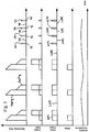
- a diagram of different indicators.
- Referring to
Fig. 1 and3 , a beverage maker 10 is depicted. The beverage maker 10 is configured for a galley of an aircraft. - The beverage maker 10 comprises a
brewing assembly 12 for preparinghot beverages 14 from hot water. Thebrewing assembly 12 may be configured for preparing coffee or tea, for example. - Furthermore, the beverage maker 10 includes a
water heating system 16 which is configured for heating water. Preferably, thewater heating system 16 is configured to keep the heated water within a predetermined temperature range. - The
water heating system 16 comprises awater tank 18 which is able to holdwater 20 to be heated. Thewater tank 18 may have a thermal insulation so as to reduce heat dissipation from thewater tank 18 to the environment. - The
water heating system 16 comprises aheating device 22. Theheating device 22 is arranged within thewater tank 18 so as to be able to heat thewater 20. - The
water heating system 16 comprises athermal sensor 24 for measuring the temperature of thewater 20. Thethermal sensor 24 can be integrated into theheating device 22. It is also possible that thethermal sensor 24 is configured separately or integrated in another suitable component of thewater heating system 16. - The
water heating system 16 includes an inlet valve 26 which controls the inlet of fresh water into thewater tank 18. Furthermore, thewater heating system 16 includes anoutlet valve 28 which controls the outlet of hot water to thebrewing assembly 12. - The
water heating system 16 comprises one or moreadditional sensors 30. Theadditional sensor 30 may be select from a group containing ambient temperature sensors, water flow sensors, and water quality sensors. - The water quality sensors may be configured for obtaining a water quality, by measuring physical parameters of the
water 30, the physical parameters being indicative of the specific heat capacityof thewater 30. As an example, the water quality sensor may be a TDS Sensor which measures the amount of total dissolved solids in thewater 30. - Two
additional sensors 30 may be water flow sensors arranged close to or integrated in the inlet valve 26 andoutlet valve 28, so as to be able to measure inflow and/or outflow. - The
water heating system 16 comprises apower supply line 32 with which thewater heating system 16 is connected to apower supply 34. Thepower supply 34 is preferably provided by an aircraft on board power grid, for example. - The
water heating system 16 also includes a powerstate indication device 36, which is configured to generate a low power consumption signal LOPC and a high power consumption signal HIPC based on the power consumed by thewater heating system 16, in particular theheating device 22. - The power
state indication device 36 comprises a power measurement device 38, such as a power clamp 40 which is suitable for measuring power consumption without direct electrical contact to thepower supply line 32. - Thus, the low power consumption signal LOPC indicates that the
heating device 22 is off, while the high power consumption signal HIPC indicates that theheating device 22 is active and heating thewater 20. - The
water heating system 16 comprises amonitoring device 42. Themonitoring device 42 is configured to monitor thewater heating system 16. Themonitoring device 42 may be implemented as a computer or microcontroller of some sort and perform various methods described below. - Furthermore, the
monitoring device 42 is connected to the power measurement device 38. - The
monitoring device 42 may be configured as a separate module. Furthermore, themonitoring device 42 need not be integrated into the beverage maker 10 or thewater heating system 16. It is also possible for themonitoring device 42 to be arranged at a different location within the aircraft. Themonitoring device 42 may be part of the powerstate indication device 36. - The
water heating system 16 comprises acontrol device 43. Thecontrol device 43 is configured to control thewater heating system 16 and possibly the beverage maker 10. Thecontrol device 43 is connected to theheating device 22 so as to switch theheating device 22 on and off to keep thewater 20 within a known temperature range. - The
control device 43 is also connected to the inlet andoutlet valves 26, 28 as well as theadditional sensors 30. - The
monitoring device 42 and thecontrol device 43 are presently described as being integrated into a single unit. It should be noted that the devices may be separate and not even within the vicinity of each other. - At the beginning of operation of the
water heating system 16 or the beverage maker 10, thecontrol device 43 fills thewater tank 18 via inlet valve 26 if necessary and activates theheating device 22 so as to heat thewater 20. - After this initial heating, the
control device 43 measures the water temperature of thewater 20 usingthermal sensor 24. If the water temperature drops below a lower threshold, theheating device 22 is activated until the water temperature exceeds an upper threshold. Thus, the water temperature is kept within a predetermined temperature range. The process between two such subsequent activations of theheating device 22 is called a reheatingcycle 44. - The time duration for which the
heating device 22 is activated, i.e. the high power consumption signal HIPC is active, is the reheating time 46. The reheating time 46 is determined by themonitoring device 42 by storing a first timestamp, when the powerstate indication device 36 changes from the low power consumption signal LOPC to the high power consumption signal HIPC, and a second time stamp, when the powerstate indication device 36 changes from the high power consumption signal HIPC to the low power consumption signal LOPC. The reheating time 46 is then determined by subtracting the first timestamp from the second time stamp. As an alternative, a timer may be used to measure the relevant time intervals instead of the timestamps. - The reheating time 46 is stored as a condition-based degradation indicator for further processing. Alternatively or additionally, the reheating time 46 may be processed further directly.
- In addition, the
monitoring device 42 may also determine the time interval between two subsequent reheating cycles 44. This time interval is called reheatingfrequency 48. - The
reheating frequency 48 is also stored as a condition-based degradation indicator for further processing. Alternatively or additionally, thereheating frequency 48 may be processed further directly. - The following pseudo code outlines the principles of the determination in case that only a power based signal, e.g. in case of minimum instrumentation of legacy beverage makers, such as beverage maker 10, is available.
- This method is an approximation as the distinction between operating cycles and subsequent heating is not easily possible, unless e.g. with additional water flow data, which can be acquired from a sensor integrated in the
outlet valve 28 for example.
 // condition-based indicators
 list<time, float> reheating_times
 list<time, float> reheating_frequency

 // usage-based indicators
 list<time, int> brew_cycles
 list<time, int> tapping_cycles
 list<time, float> heating_time
 list<time, float> water_flow

 // constants to be defined per equipment model
 REHEATING_THRESHOLD
 BREW_CYCLE_TIME
 BREW_CYCLE_FLOW
 TAPPING_FLOW

 // feature extraction method for power
 foreach timestep i

   // identify start of HIGH power consumption
   if (POWER_STATE(i-1) == LOW && POWER_STATE(i) == HIGH)
   start_time = current_time(i)

   // identify time between two consecutive reheating cycles
   if (last_cycle_type == 'REHEATING')
     add reheating_frequency(start_time, (start_time-
     stop_time))

   // identify end of HIGH power consumption
   if (POWER_STATE (i-1) == HIGH && POWER_STATE(i) == LOW)
    stop_time = current_time(i)

     // identify duration of heating cycle
     cycle_time = stop_time - start_time
     add heating_time(start_time, cycle_time)

     // identify reheating cycles
     if (cycle_time < REHEATING_THRESHOLD)
     last_cycle_type = 'REHEATING'
     add reheating_times(start_time, cycle_time)

     // identify brew cycles (incl. subsequent heating) else
     if (cycle_time > BREW_CYCLE_TIME)
     last_cycle_type = 'BREW'
     add brew_cycles(start_time, 1)
     add water_flow(start_time, BREW_CYCLE_FLOW)

     // identify tapping cycles (incl. subsequent heating)
     else if (cycle_time < BREW_CYCLE_TIME)
        last_cycle_type = 'TAPPING'
        add tapping_cycles(start_time, 1)
        add water_flow (start_time, TAPPING_FLOW * cycle_time)
 // condition-based indicators
 list<time, float> reheating_times
 list<time, float> reheating_frequency

 // usage-based indicators
 list<time, int> brew_cycles
 list<time, int> tapping_cycles
 list<time, float> heating_time
 list<time, float> water_flow

 // constants to be defined per equipment model
 MINIMUM_TIME_VALUE_FOR_PBR
 CATERING_TIME_VALUE_FOR_PBR
 REHEATING_THRESHOLD
 BREW_CYCLE_TIME
 BREW_CYCLE_FLOW
 TAPPING_FLOW

 // feature extraction algorithm for ARINC 812
 foreach timestep i

   // identify start of heating cycle
   if (HEATER_STATE (i-1) == 'STANDBY_ON' && HEATER_STATE (i)
   == 'ON')
   start_time = current_time(i)
   timer_for_pbr = current_timer_value(i)

     // identify time between two consecutive reheating cycles
     if (last_cycle_type == 'REHEATING')
     add reheating_frequency(start_time, (start_time -
     stop_time))

   // identify end of heating cycle
   if (HEATER_STATE (i-1) == 'ON' && HEATER_STATE (i) ==
   'FINISHED')
     stop_time = current_time(i)

     // identify duration of heating cycle
     cycle_time = stop_time - start_time
     add heating_time(start_time, cycle_time)

     // identify reheating cycles
     if (timer_for_pbr == MINIMUM_TIME_VALUE_FOR_PBR && cy-
     cle_time < REHEATING_THRESHOLD)
     last_cycle_type = 'REHEATING'
     add reheating_times(start_time, cycle_time)

     // identify heating cycle following brew and/or tapping
     cycle
     if (last_cycle_type == 'BREW' || last_cycle_type ==
      'TAPPING' || last_cycle_type == 'BREW/TAPPING')
     last_cycle_type = 'HEATING-UP'

     // could be used to reverse calculate water inflow tem-
     perature etc.

     // identify brew cycles (excl. subsequent heating)
     else if (timer_for_pbr == CATERING_TIME_VALUE_FOR_PBR &&
     cycle_time ∼ = BREW_CYCLE_TIME)
     last_cycle_type = 'BREW'
     add brew_cycles(start_time, 1)
     add water_flow(start_time, BREW_CYCLE_FLOW)

     // identify tapping cycles (excl. subsequent heating)
     else if (timer_for_pbr == CATERING_TIME_VALUE_FOR_PBR &&
     cycle_time < BREW_CYCLE_TIME)
     last_cycle_type = 'TAPPING'
     add tapping_cycles(start_time, 1)
     add water_flow (start_time, TAPPING_FLOW * cycle_time)

     // identify combined brew and tapping cycles (excl. sub-
     sequent heating)
     else if (timer_for_pbr == CATERING_TIME_VALUE_FOR_PBR &&
     cycle_time > BREW_CYCLE_TIME)
     last_cycle_type = 'BREW/TAPPING'
     add brew_cycles(start_time, 1)
     add tapping_cycles(start_time, 1)
     add water_flow(start_time, BREW_CYCLE_FLOW + (TAP-
     PING_FLOW * (cycle_time - BREW_CYCLE_TIME))
- 10
- beverage maker
- 12
- brewing assembly
- 14
- hot beverage
- 16
- water heating system
- 18
- water tank
- 20
- water
- 22
- heating device
- 24
- thermal sensor
- 26
- inlet valve
- 28
- outlet valve
- 30
- additional sensor
- 32
- power supply line
- 34
- power supply
- 36
- power state indication device
- 38
- power measurement device
- 40
- power clamp
- 42
- monitoring device
- 43
- control device
- 44
- reheating cycle
- 46
- reheating time
- 48
- reheating frequency
- 50
- predictive maintenance device
- 52
- beverage maker
- 54
- communication interface
- 56
- heater state communication interface
Claims (15)
- Indicator generating method for generating an indicator which is suitable for maintenance prediction of a water heating system (16), the water heating system (16) comprising a water tank (18) containing water (20) to be heated by a heating device (22), a power state indication device (36) and a monitoring device (42), the method comprising:the power state indication device (36) generating at least a low power consumption signal or a high power consumption signal based on the power consumption of the heating device (22);the monitoring device (42) determining a condition-based degradation indicator based on the time duration of the high power consumption signal;wherein the monitoring device (42) outputs the condition-based degradation indicator for further processing in a predictive maintenance device (50).
- Method according to any of the preceding claims, wherein the power state indication device (36) includes a power measurement device (38) which measures the power consumption caused by the heating device (22) and generates the high power consumption signal, if the power consumption exceeds a predetermined high power threshold, and/or generates the low power consumption signal, if the power consumption drops below a predetermined low power threshold.
- Method according to any of the preceding claims, wherein the power state indicator device (36) includes a communication interface (56) which outputs the current water heating system state to an inter-device communications network, from which the monitoring device (42) is able to obtain the water heating system state and able to generate the low power consumption signal and/or high power consumption signal depending on the obtained heater state.
- Method according to any of the preceding claims, wherein the monitoring device (42) determines a reheating time (46), which is the time duration of the high power consumption signal, and outputs the reheating time as a condition-based degradation indicator.
- Method according to any of the preceding claims, wherein the monitoring device (42) determines a condition-based degradation indicator also based on the time interval between two subsequent high power consumption signals.
- Method according to any of the preceding claims, wherein the monitoring device (42) determines a reheating frequency (48), which is the time interval between two subsequent high power consumption signals, and additionally outputs reheating frequency (44) as a condition-based degradation indicator.
- Method according to any of the preceding claims, wherein the water heating system (16) comprises at least one additional sensor (30), wherein each additional sensor (30) is configured for measuring at least one of an additional physical quantity and the ambient temperature, wherein the monitoring device (42) additionally processes the measured quantity or temperature for generating the indicator.
- Method according to any of the preceding claims, wherein the monitoring device (42) determines a usage-based indicator based on sensor data and/or state information available on an inter-device communications network or the additional sensor (30).
- Method according to any of the preceding claims, wherein the usage-based indicator includes the number of operation cycles, heating times, water quality, and/or water flows.
- Method according to any of the preceding claims, wherein the water heating system (16) comprises a water flow sensor, which measures the presence of water flow to or from the tank, and the monitoring device (42) discards high power consumption signals as reheating cycle, if the water flow sensor detects presence of a water flow, and/or the monitoring device additionally outputs the water flow sensor data as the usage-based indicator.
- Predictive maintenance method for generating a maintenance signal, which indicates that a water heating system (16) monitored by a predictive maintenance device (50) requires maintenance, the water heating system (16) comprising a water tank (18) containing water (20) to be heated by a heating device (22), a power state indication device (36) and a monitoring device (42), the method comprising:performing an indicator generating method according to any of the preceding claims, so as to generate at least a condition-based degradation indicator;the predictive maintenance device determining a remaining useful lifetime based on the indicator from the previous step, preferably by processing the condition-based degradation indicator and/or other indicators using a predictive maintenance model;the predictive maintenance device (50) outputting the maintenance signal, if the remaining useful lifetime or the condition based indicator or the usage based indicator drops below a predetermined threshold.
- Method according to claim 11, wherein- the condition-based degradation indicator includes a reheating time (46), and the predictive maintenance device (50) determines the remaining useful lifetime such that the remaining useful lifetime decreases, if the reheating time (46) increases; and/or- the condition-based degradation indicator includes a reheating frequency (48), and the predictive maintenance device (50) determines the remaining useful lifetime such that the remaining useful lifetime decreases, if the reheating frequency (48) decreases; and/or- the condition-based degradation indicator includes an ambient temperature and/or water quality, and the predictive maintenance device (50) determines the remaining useful lifetime such that the remaining useful lifetime decreases, if the predictive maintenance device (50) determines that the reheating time (46) is larger than and/or the reheating frequency (48) is smaller than an expected value for the reheating time (46) and/or reheating frequency (48), wherein preferably the expected value is determined based on the ambient temperature and/or water quality.
- Water heating system (16) for a beverage maker (10, 52) of an aircraft galley, the water heating system (16) configured for heating water and comprising a water tank (18) suitable to hold water (20) to be heated, a heating device (22) configured for heating the water (20) within the water tank (18), a power state indication device (36) configured for generating at least a low power consumption signal or a high power consumption signal based on the power consumption of the heating device (22); and a monitoring device (42) configured for performing an indicator generating method according to any of the claims 1 to 10 or a predictive maintenance method according to any of the claims 11 or 12.
- Beverage maker (10, 52), in particular coffee maker or tea maker, for an aircraft galley comprising a water heating system (16) according to claim 13.
- Data medium containing instructions for a computer system (42), which, when executed by the computer system (42), perform a method according to any of the claims 1 to 14.
Applications Claiming Priority (1)
| Application Number | Priority Date | Filing Date | Title |
|---|---|---|---|
| IN201911039534 | 2019-09-30 |
Publications (2)
| Publication Number | Publication Date |
|---|---|
| EP3798529A1 true EP3798529A1 (en) | 2021-03-31 |
| EP3798529B1 EP3798529B1 (en) | 2023-07-12 |
Family
ID=68621143
Family Applications (1)
| Application Number | Title | Priority Date | Filing Date |
|---|---|---|---|
| EP19210271.3A Active EP3798529B1 (en) | 2019-09-30 | 2019-11-20 | Indicator generating method and predictive maintenance method for failure prediction for a water heating system, such water heating system, and beverage maker |
Country Status (2)
| Country | Link |
|---|---|
| US (1) | US11519613B2 (en) |
| EP (1) | EP3798529B1 (en) |
Families Citing this family (16)
| Publication number | Priority date | Publication date | Assignee | Title |
|---|---|---|---|---|
| US12622889B2 (en) | 2016-04-19 | 2026-05-12 | Axcess Global Sciences, Llc | S-β-hydroxybutyrate esters for improving metabolic function |
| US12109182B2 (en) | 2016-04-19 | 2024-10-08 | Axcess Global Sciences, Llc | Administration of R-beta-hydroxybutyrate and related compounds in humans |
| US12599579B2 (en) | 2016-04-19 | 2026-04-14 | Axcess Global Sciences, Llc | Compositions and compounds containing ketone bodies and/or ketone body precursors and one or more amino acids |
| US12496283B2 (en) | 2016-04-19 | 2025-12-16 | Axcess Global Sciences, Llc | Administration of R-beta-hydroxybutyrate and related compounds in humans |
| US12533346B2 (en) | 2016-04-19 | 2026-01-27 | Axcess Global Sciences, Llc | Administration of berberine metabolites |
| US20230346721A1 (en) | 2018-04-18 | 2023-11-02 | Axcess Global Sciences, Llc | Beta-hydroxybutyric acid compositions and methods for delivery of ketone bodies |
| US12521378B2 (en) | 2016-04-19 | 2026-01-13 | Axcess Global Sciences, Llc | Administration of R-beta-hydroxybutyrate salt blend and related compounds in humans |
| US12329734B2 (en) | 2017-12-19 | 2025-06-17 | Axcess Global Sciences, Llc | Use of S-beta-hydroxybutyrate compounds for induction and maintenance of flow |
| US10925843B2 (en) | 2018-04-18 | 2021-02-23 | Axcess Global Sciences, Llc | Compositions and methods for keto stacking with beta-hydroxybutyrate and acetoacetate |
| US12090129B2 (en) | 2017-11-22 | 2024-09-17 | Axcess Global Sciences, Llc | Non-racemic beta-hydroxybutyrate compounds and compositions enriched with the R-enantiomer and methods of use |
| US20210247295A1 (en) * | 2020-02-06 | 2021-08-12 | B/E Aerospace, Inc. | System and Method for Detecting Limescale Buildup in Aircraft Brewing Apparatuses |
| US12472200B2 (en) | 2019-05-15 | 2025-11-18 | Axcess Global Sciences, Llc | Autobiotic compositions and method for promoting healthy gut microbiome |
| US11969430B1 (en) | 2023-03-10 | 2024-04-30 | Axcess Global Sciences, Llc | Compositions containing paraxanthine and beta-hydroxybutyrate or precursor for increasing neurological and physiological performance |
| US12167993B2 (en) | 2019-06-21 | 2024-12-17 | Axcess Global Sciences, Llc | Non-vasoconstricting energy-promoting compositions containing ketone bodies |
| US12186297B2 (en) | 2020-08-26 | 2025-01-07 | Axcess Global Sciences, Llc | Compositions and methods for increasing lean-to-fat mass ratio |
| EP4151527A1 (en) * | 2021-09-17 | 2023-03-22 | Airbus Operations GmbH | A galley unit with hot water supply |
Citations (6)
| Publication number | Priority date | Publication date | Assignee | Title |
|---|---|---|---|---|
| JP2007132599A (en) * | 2005-11-10 | 2007-05-31 | Corona Corp | Controller for storage water heater |
| US20100193593A1 (en) * | 2007-02-06 | 2010-08-05 | Rheem Manufacturing Company | Water Heater Monitor/Diagnostic Display Apparatus |
| US20110095010A1 (en) | 2009-10-23 | 2011-04-28 | Bondarowicz Frank A | Water tank heater with predictive heater failure feature |
| JP2012255568A (en) * | 2011-06-07 | 2012-12-27 | Mitsubishi Heavy Ind Ltd | Storage type water heater |
| FR2995982A1 (en) * | 2012-09-27 | 2014-03-28 | Schneider Electric Ind Sas | Method for controlling degradation of electric water heater in home, involves generating degradation alarm if result of comparison of degradation coefficient of resistor with reference degradation coefficient value exceeds preset threshold |
| US20160178221A1 (en) * | 2014-12-22 | 2016-06-23 | Battelle Memorial Institute | Estimation of unknown states for an electric water heater with thermal stratification and use of same in demand response and condition-based maintenance |
Family Cites Families (1)
| Publication number | Priority date | Publication date | Assignee | Title |
|---|---|---|---|---|
| CA2865710A1 (en) * | 2012-03-13 | 2013-09-19 | Driessen Aerospace Group N.V. | Power management for galley with fuel cell |
-
2019
- 2019-11-20 EP EP19210271.3A patent/EP3798529B1/en active Active
-
2020
- 2020-09-28 US US17/034,275 patent/US11519613B2/en active Active
Patent Citations (6)
| Publication number | Priority date | Publication date | Assignee | Title |
|---|---|---|---|---|
| JP2007132599A (en) * | 2005-11-10 | 2007-05-31 | Corona Corp | Controller for storage water heater |
| US20100193593A1 (en) * | 2007-02-06 | 2010-08-05 | Rheem Manufacturing Company | Water Heater Monitor/Diagnostic Display Apparatus |
| US20110095010A1 (en) | 2009-10-23 | 2011-04-28 | Bondarowicz Frank A | Water tank heater with predictive heater failure feature |
| JP2012255568A (en) * | 2011-06-07 | 2012-12-27 | Mitsubishi Heavy Ind Ltd | Storage type water heater |
| FR2995982A1 (en) * | 2012-09-27 | 2014-03-28 | Schneider Electric Ind Sas | Method for controlling degradation of electric water heater in home, involves generating degradation alarm if result of comparison of degradation coefficient of resistor with reference degradation coefficient value exceeds preset threshold |
| US20160178221A1 (en) * | 2014-12-22 | 2016-06-23 | Battelle Memorial Institute | Estimation of unknown states for an electric water heater with thermal stratification and use of same in demand response and condition-based maintenance |
Also Published As
| Publication number | Publication date |
|---|---|
| US11519613B2 (en) | 2022-12-06 |
| US20210095867A1 (en) | 2021-04-01 |
| EP3798529B1 (en) | 2023-07-12 |
Similar Documents
| Publication | Publication Date | Title |
|---|---|---|
| EP3798529B1 (en) | Indicator generating method and predictive maintenance method for failure prediction for a water heating system, such water heating system, and beverage maker | |
| EP3183510B1 (en) | System for determining scaling in a boiler | |
| US20160178221A1 (en) | Estimation of unknown states for an electric water heater with thermal stratification and use of same in demand response and condition-based maintenance | |
| EP4009266A1 (en) | System and method for operating unmanned cafe | |
| US11006778B2 (en) | Electrically operated beverage maker (preferably coffee machine) having dynamic maintenance plan generation | |
| CN103534556B (en) | Flow measurement device | |
| EP3358317B1 (en) | Meter and meter system | |
| EP2369233A1 (en) | Gas shut-off device | |
| EP3259414B1 (en) | Pump monitoring system and method | |
| US11596288B2 (en) | System for determining an operating state of a dishwasher and an according method | |
| EP2383513A1 (en) | Gas shutoff device | |
| US20100070213A1 (en) | Method for Monitoring the Electrical Energy Quality in an Electrical Energy Supply System, Power Quality Field Device and Power Quality System | |
| CN101614554A (en) | Continuous physical measuring device and method | |
| EP2743602B1 (en) | Detection of anomalies in a system for supplying hot water | |
| JP2006039786A (en) | Plant data estimation system and method, condenser vacuum monitoring method, data mining method, and program | |
| US20240182289A1 (en) | Beverage dispensing machine network | |
| WO2020242851A1 (en) | Estimation of temperature states for an electric water heater from inferred resistance measurement | |
| CN113418304B (en) | Control method, device, equipment and computer-readable storage medium for water heater | |
| CN111928486A (en) | Heat pump water heater and electricity saving amount determining method and device thereof and storage medium | |
| CA3004773C (en) | Detecting an error condition by monitoring a resource flow at a premises | |
| EP3677879B1 (en) | Flow rate measurement device | |
| KR101537357B1 (en) | Method and apparatus for monitoring semiconductor process and recording medium thereof | |
| US11215487B2 (en) | Flow rate measurement device | |
| CN113358192B (en) | Detecting abnormal metering drift in flow meters | |
| WO2021144902A1 (en) | Energy use amount calculation device, used power amount monitoring system and program |
Legal Events
| Date | Code | Title | Description |
|---|---|---|---|
| PUAI | Public reference made under article 153(3) epc to a published international application that has entered the european phase |
Free format text: ORIGINAL CODE: 0009012 |
|
| STAA | Information on the status of an ep patent application or granted ep patent |
Free format text: STATUS: THE APPLICATION HAS BEEN PUBLISHED |
|
| AK | Designated contracting states |
Kind code of ref document: A1 Designated state(s): AL AT BE BG CH CY CZ DE DK EE ES FI FR GB GR HR HU IE IS IT LI LT LU LV MC MK MT NL NO PL PT RO RS SE SI SK SM TR |
|
| AX | Request for extension of the european patent |
Extension state: BA ME |
|
| STAA | Information on the status of an ep patent application or granted ep patent |
Free format text: STATUS: REQUEST FOR EXAMINATION WAS MADE |
|
| 17P | Request for examination filed |
Effective date: 20210930 |
|
| RBV | Designated contracting states (corrected) |
Designated state(s): AL AT BE BG CH CY CZ DE DK EE ES FI FR GB GR HR HU IE IS IT LI LT LU LV MC MK MT NL NO PL PT RO RS SE SI SK SM TR |
|
| GRAP | Despatch of communication of intention to grant a patent |
Free format text: ORIGINAL CODE: EPIDOSNIGR1 |
|
| STAA | Information on the status of an ep patent application or granted ep patent |
Free format text: STATUS: GRANT OF PATENT IS INTENDED |
|
| INTG | Intention to grant announced |
Effective date: 20220914 |
|
| GRAJ | Information related to disapproval of communication of intention to grant by the applicant or resumption of examination proceedings by the epo deleted |
Free format text: ORIGINAL CODE: EPIDOSDIGR1 |
|
| STAA | Information on the status of an ep patent application or granted ep patent |
Free format text: STATUS: REQUEST FOR EXAMINATION WAS MADE |
|
| GRAP | Despatch of communication of intention to grant a patent |
Free format text: ORIGINAL CODE: EPIDOSNIGR1 |
|
| STAA | Information on the status of an ep patent application or granted ep patent |
Free format text: STATUS: GRANT OF PATENT IS INTENDED |
|
| INTC | Intention to grant announced (deleted) | ||
| INTG | Intention to grant announced |
Effective date: 20230131 |
|
| GRAS | Grant fee paid |
Free format text: ORIGINAL CODE: EPIDOSNIGR3 |
|
| GRAA | (expected) grant |
Free format text: ORIGINAL CODE: 0009210 |
|
| STAA | Information on the status of an ep patent application or granted ep patent |
Free format text: STATUS: THE PATENT HAS BEEN GRANTED |
|
| AK | Designated contracting states |
Kind code of ref document: B1 Designated state(s): AL AT BE BG CH CY CZ DE DK EE ES FI FR GB GR HR HU IE IS IT LI LT LU LV MC MK MT NL NO PL PT RO RS SE SI SK SM TR |
|
| REG | Reference to a national code |
Ref country code: CH Ref legal event code: EP |
|
| REG | Reference to a national code |
Ref country code: IE Ref legal event code: FG4D |
|
| REG | Reference to a national code |
Ref country code: DE Ref legal event code: R096 Ref document number: 602019032467 Country of ref document: DE |
|
| REG | Reference to a national code |
Ref country code: LT Ref legal event code: MG9D |
|
| REG | Reference to a national code |
Ref country code: NL Ref legal event code: MP Effective date: 20230712 |
|
| REG | Reference to a national code |
Ref country code: AT Ref legal event code: MK05 Ref document number: 1587568 Country of ref document: AT Kind code of ref document: T Effective date: 20230712 |
|
| PG25 | Lapsed in a contracting state [announced via postgrant information from national office to epo] |
Ref country code: NL Free format text: LAPSE BECAUSE OF FAILURE TO SUBMIT A TRANSLATION OF THE DESCRIPTION OR TO PAY THE FEE WITHIN THE PRESCRIBED TIME-LIMIT Effective date: 20230712 |
|
| PG25 | Lapsed in a contracting state [announced via postgrant information from national office to epo] |
Ref country code: GR Free format text: LAPSE BECAUSE OF FAILURE TO SUBMIT A TRANSLATION OF THE DESCRIPTION OR TO PAY THE FEE WITHIN THE PRESCRIBED TIME-LIMIT Effective date: 20231013 |
|
| PG25 | Lapsed in a contracting state [announced via postgrant information from national office to epo] |
Ref country code: ES Free format text: LAPSE BECAUSE OF FAILURE TO SUBMIT A TRANSLATION OF THE DESCRIPTION OR TO PAY THE FEE WITHIN THE PRESCRIBED TIME-LIMIT Effective date: 20230712 |
|
| PG25 | Lapsed in a contracting state [announced via postgrant information from national office to epo] |
Ref country code: IS Free format text: LAPSE BECAUSE OF FAILURE TO SUBMIT A TRANSLATION OF THE DESCRIPTION OR TO PAY THE FEE WITHIN THE PRESCRIBED TIME-LIMIT Effective date: 20231112 |
|
| PG25 | Lapsed in a contracting state [announced via postgrant information from national office to epo] |
Ref country code: SE Free format text: LAPSE BECAUSE OF FAILURE TO SUBMIT A TRANSLATION OF THE DESCRIPTION OR TO PAY THE FEE WITHIN THE PRESCRIBED TIME-LIMIT Effective date: 20230712 Ref country code: RS Free format text: LAPSE BECAUSE OF FAILURE TO SUBMIT A TRANSLATION OF THE DESCRIPTION OR TO PAY THE FEE WITHIN THE PRESCRIBED TIME-LIMIT Effective date: 20230712 Ref country code: PT Free format text: LAPSE BECAUSE OF FAILURE TO SUBMIT A TRANSLATION OF THE DESCRIPTION OR TO PAY THE FEE WITHIN THE PRESCRIBED TIME-LIMIT Effective date: 20231113 Ref country code: NO Free format text: LAPSE BECAUSE OF FAILURE TO SUBMIT A TRANSLATION OF THE DESCRIPTION OR TO PAY THE FEE WITHIN THE PRESCRIBED TIME-LIMIT Effective date: 20231012 Ref country code: LV Free format text: LAPSE BECAUSE OF FAILURE TO SUBMIT A TRANSLATION OF THE DESCRIPTION OR TO PAY THE FEE WITHIN THE PRESCRIBED TIME-LIMIT Effective date: 20230712 Ref country code: LT Free format text: LAPSE BECAUSE OF FAILURE TO SUBMIT A TRANSLATION OF THE DESCRIPTION OR TO PAY THE FEE WITHIN THE PRESCRIBED TIME-LIMIT Effective date: 20230712 Ref country code: IS Free format text: LAPSE BECAUSE OF FAILURE TO SUBMIT A TRANSLATION OF THE DESCRIPTION OR TO PAY THE FEE WITHIN THE PRESCRIBED TIME-LIMIT Effective date: 20231112 Ref country code: HR Free format text: LAPSE BECAUSE OF FAILURE TO SUBMIT A TRANSLATION OF THE DESCRIPTION OR TO PAY THE FEE WITHIN THE PRESCRIBED TIME-LIMIT Effective date: 20230712 Ref country code: GR Free format text: LAPSE BECAUSE OF FAILURE TO SUBMIT A TRANSLATION OF THE DESCRIPTION OR TO PAY THE FEE WITHIN THE PRESCRIBED TIME-LIMIT Effective date: 20231013 Ref country code: FI Free format text: LAPSE BECAUSE OF FAILURE TO SUBMIT A TRANSLATION OF THE DESCRIPTION OR TO PAY THE FEE WITHIN THE PRESCRIBED TIME-LIMIT Effective date: 20230712 Ref country code: ES Free format text: LAPSE BECAUSE OF FAILURE TO SUBMIT A TRANSLATION OF THE DESCRIPTION OR TO PAY THE FEE WITHIN THE PRESCRIBED TIME-LIMIT Effective date: 20230712 Ref country code: AT Free format text: LAPSE BECAUSE OF FAILURE TO SUBMIT A TRANSLATION OF THE DESCRIPTION OR TO PAY THE FEE WITHIN THE PRESCRIBED TIME-LIMIT Effective date: 20230712 |
|
| PG25 | Lapsed in a contracting state [announced via postgrant information from national office to epo] |
Ref country code: PL Free format text: LAPSE BECAUSE OF FAILURE TO SUBMIT A TRANSLATION OF THE DESCRIPTION OR TO PAY THE FEE WITHIN THE PRESCRIBED TIME-LIMIT Effective date: 20230712 |
|
| REG | Reference to a national code |
Ref country code: DE Ref legal event code: R097 Ref document number: 602019032467 Country of ref document: DE |
|
| PG25 | Lapsed in a contracting state [announced via postgrant information from national office to epo] |
Ref country code: SM Free format text: LAPSE BECAUSE OF FAILURE TO SUBMIT A TRANSLATION OF THE DESCRIPTION OR TO PAY THE FEE WITHIN THE PRESCRIBED TIME-LIMIT Effective date: 20230712 Ref country code: RO Free format text: LAPSE BECAUSE OF FAILURE TO SUBMIT A TRANSLATION OF THE DESCRIPTION OR TO PAY THE FEE WITHIN THE PRESCRIBED TIME-LIMIT Effective date: 20230712 Ref country code: EE Free format text: LAPSE BECAUSE OF FAILURE TO SUBMIT A TRANSLATION OF THE DESCRIPTION OR TO PAY THE FEE WITHIN THE PRESCRIBED TIME-LIMIT Effective date: 20230712 Ref country code: DK Free format text: LAPSE BECAUSE OF FAILURE TO SUBMIT A TRANSLATION OF THE DESCRIPTION OR TO PAY THE FEE WITHIN THE PRESCRIBED TIME-LIMIT Effective date: 20230712 Ref country code: CZ Free format text: LAPSE BECAUSE OF FAILURE TO SUBMIT A TRANSLATION OF THE DESCRIPTION OR TO PAY THE FEE WITHIN THE PRESCRIBED TIME-LIMIT Effective date: 20230712 Ref country code: SK Free format text: LAPSE BECAUSE OF FAILURE TO SUBMIT A TRANSLATION OF THE DESCRIPTION OR TO PAY THE FEE WITHIN THE PRESCRIBED TIME-LIMIT Effective date: 20230712 |
|
| PLBE | No opposition filed within time limit |
Free format text: ORIGINAL CODE: 0009261 |
|
| STAA | Information on the status of an ep patent application or granted ep patent |
Free format text: STATUS: NO OPPOSITION FILED WITHIN TIME LIMIT |
|
| PG25 | Lapsed in a contracting state [announced via postgrant information from national office to epo] |
Ref country code: IT Free format text: LAPSE BECAUSE OF FAILURE TO SUBMIT A TRANSLATION OF THE DESCRIPTION OR TO PAY THE FEE WITHIN THE PRESCRIBED TIME-LIMIT Effective date: 20230712 |
|
| 26N | No opposition filed |
Effective date: 20240415 |
|
| REG | Reference to a national code |
Ref country code: CH Ref legal event code: PL |
|
| PG25 | Lapsed in a contracting state [announced via postgrant information from national office to epo] |
Ref country code: MC Free format text: LAPSE BECAUSE OF FAILURE TO SUBMIT A TRANSLATION OF THE DESCRIPTION OR TO PAY THE FEE WITHIN THE PRESCRIBED TIME-LIMIT Effective date: 20230712 |
|
| PG25 | Lapsed in a contracting state [announced via postgrant information from national office to epo] |
Ref country code: LU Free format text: LAPSE BECAUSE OF NON-PAYMENT OF DUE FEES Effective date: 20231120 |
|
| PG25 | Lapsed in a contracting state [announced via postgrant information from national office to epo] |
Ref country code: CH Free format text: LAPSE BECAUSE OF NON-PAYMENT OF DUE FEES Effective date: 20231130 |
|
| PG25 | Lapsed in a contracting state [announced via postgrant information from national office to epo] |
Ref country code: MC Free format text: LAPSE BECAUSE OF FAILURE TO SUBMIT A TRANSLATION OF THE DESCRIPTION OR TO PAY THE FEE WITHIN THE PRESCRIBED TIME-LIMIT Effective date: 20230712 Ref country code: LU Free format text: LAPSE BECAUSE OF NON-PAYMENT OF DUE FEES Effective date: 20231120 Ref country code: CH Free format text: LAPSE BECAUSE OF NON-PAYMENT OF DUE FEES Effective date: 20231130 Ref country code: SI Free format text: LAPSE BECAUSE OF FAILURE TO SUBMIT A TRANSLATION OF THE DESCRIPTION OR TO PAY THE FEE WITHIN THE PRESCRIBED TIME-LIMIT Effective date: 20230712 |
|
| REG | Reference to a national code |
Ref country code: BE Ref legal event code: MM Effective date: 20231130 |
|
| REG | Reference to a national code |
Ref country code: IE Ref legal event code: MM4A |
|
| PG25 | Lapsed in a contracting state [announced via postgrant information from national office to epo] |
Ref country code: IE Free format text: LAPSE BECAUSE OF NON-PAYMENT OF DUE FEES Effective date: 20231120 |
|
| PG25 | Lapsed in a contracting state [announced via postgrant information from national office to epo] |
Ref country code: BE Free format text: LAPSE BECAUSE OF NON-PAYMENT OF DUE FEES Effective date: 20231130 |
|
| PG25 | Lapsed in a contracting state [announced via postgrant information from national office to epo] |
Ref country code: IE Free format text: LAPSE BECAUSE OF NON-PAYMENT OF DUE FEES Effective date: 20231120 Ref country code: BE Free format text: LAPSE BECAUSE OF NON-PAYMENT OF DUE FEES Effective date: 20231130 |
|
| PG25 | Lapsed in a contracting state [announced via postgrant information from national office to epo] |
Ref country code: BG Free format text: LAPSE BECAUSE OF FAILURE TO SUBMIT A TRANSLATION OF THE DESCRIPTION OR TO PAY THE FEE WITHIN THE PRESCRIBED TIME-LIMIT Effective date: 20230712 |
|
| PG25 | Lapsed in a contracting state [announced via postgrant information from national office to epo] |
Ref country code: BG Free format text: LAPSE BECAUSE OF FAILURE TO SUBMIT A TRANSLATION OF THE DESCRIPTION OR TO PAY THE FEE WITHIN THE PRESCRIBED TIME-LIMIT Effective date: 20230712 |
|
| PG25 | Lapsed in a contracting state [announced via postgrant information from national office to epo] |
Ref country code: CY Free format text: LAPSE BECAUSE OF FAILURE TO SUBMIT A TRANSLATION OF THE DESCRIPTION OR TO PAY THE FEE WITHIN THE PRESCRIBED TIME-LIMIT; INVALID AB INITIO Effective date: 20191120 |
|
| PG25 | Lapsed in a contracting state [announced via postgrant information from national office to epo] |
Ref country code: HU Free format text: LAPSE BECAUSE OF FAILURE TO SUBMIT A TRANSLATION OF THE DESCRIPTION OR TO PAY THE FEE WITHIN THE PRESCRIBED TIME-LIMIT; INVALID AB INITIO Effective date: 20191120 |
|
| PG25 | Lapsed in a contracting state [announced via postgrant information from national office to epo] |
Ref country code: TR Free format text: LAPSE BECAUSE OF FAILURE TO SUBMIT A TRANSLATION OF THE DESCRIPTION OR TO PAY THE FEE WITHIN THE PRESCRIBED TIME-LIMIT Effective date: 20230712 |
|
| PGFP | Annual fee paid to national office [announced via postgrant information from national office to epo] |
Ref country code: DE Payment date: 20251119 Year of fee payment: 7 |
|
| PGFP | Annual fee paid to national office [announced via postgrant information from national office to epo] |
Ref country code: GB Payment date: 20251121 Year of fee payment: 7 |
|
| PGFP | Annual fee paid to national office [announced via postgrant information from national office to epo] |
Ref country code: FR Payment date: 20251126 Year of fee payment: 7 |