EP3798505A1 - Illuminating lighting fixture - Google Patents
Illuminating lighting fixture Download PDFInfo
- Publication number
- EP3798505A1 EP3798505A1 EP19898802.4A EP19898802A EP3798505A1 EP 3798505 A1 EP3798505 A1 EP 3798505A1 EP 19898802 A EP19898802 A EP 19898802A EP 3798505 A1 EP3798505 A1 EP 3798505A1
- Authority
- EP
- European Patent Office
- Prior art keywords
- light source
- snap
- lighting fixture
- lens unit
- source panel
- Prior art date
- Legal status (The legal status is an assumption and is not a legal conclusion. Google has not performed a legal analysis and makes no representation as to the accuracy of the status listed.)
- Pending
Links
Images



Classifications
-
- F—MECHANICAL ENGINEERING; LIGHTING; HEATING; WEAPONS; BLASTING
- F21—LIGHTING
- F21V—FUNCTIONAL FEATURES OR DETAILS OF LIGHTING DEVICES OR SYSTEMS THEREOF; STRUCTURAL COMBINATIONS OF LIGHTING DEVICES WITH OTHER ARTICLES, NOT OTHERWISE PROVIDED FOR
- F21V17/00—Fastening of component parts of lighting devices, e.g. shades, globes, refractors, reflectors, filters, screens, grids or protective cages
- F21V17/06—Fastening of component parts of lighting devices, e.g. shades, globes, refractors, reflectors, filters, screens, grids or protective cages the fastening being onto or by the lampholder
-
- F—MECHANICAL ENGINEERING; LIGHTING; HEATING; WEAPONS; BLASTING
- F21—LIGHTING
- F21S—NON-PORTABLE LIGHTING DEVICES; SYSTEMS THEREOF; VEHICLE LIGHTING DEVICES SPECIALLY ADAPTED FOR VEHICLE EXTERIORS
- F21S8/00—Lighting devices intended for fixed installation
- F21S8/08—Lighting devices intended for fixed installation with a standard
- F21S8/085—Lighting devices intended for fixed installation with a standard of high-built type, e.g. street light
-
- F—MECHANICAL ENGINEERING; LIGHTING; HEATING; WEAPONS; BLASTING
- F21—LIGHTING
- F21V—FUNCTIONAL FEATURES OR DETAILS OF LIGHTING DEVICES OR SYSTEMS THEREOF; STRUCTURAL COMBINATIONS OF LIGHTING DEVICES WITH OTHER ARTICLES, NOT OTHERWISE PROVIDED FOR
- F21V17/00—Fastening of component parts of lighting devices, e.g. shades, globes, refractors, reflectors, filters, screens, grids or protective cages
- F21V17/10—Fastening of component parts of lighting devices, e.g. shades, globes, refractors, reflectors, filters, screens, grids or protective cages characterised by specific fastening means or way of fastening
- F21V17/16—Fastening of component parts of lighting devices, e.g. shades, globes, refractors, reflectors, filters, screens, grids or protective cages characterised by specific fastening means or way of fastening by deformation of parts; Snap action mounting
-
- F—MECHANICAL ENGINEERING; LIGHTING; HEATING; WEAPONS; BLASTING
- F21—LIGHTING
- F21V—FUNCTIONAL FEATURES OR DETAILS OF LIGHTING DEVICES OR SYSTEMS THEREOF; STRUCTURAL COMBINATIONS OF LIGHTING DEVICES WITH OTHER ARTICLES, NOT OTHERWISE PROVIDED FOR
- F21V17/00—Fastening of component parts of lighting devices, e.g. shades, globes, refractors, reflectors, filters, screens, grids or protective cages
- F21V17/10—Fastening of component parts of lighting devices, e.g. shades, globes, refractors, reflectors, filters, screens, grids or protective cages characterised by specific fastening means or way of fastening
- F21V17/16—Fastening of component parts of lighting devices, e.g. shades, globes, refractors, reflectors, filters, screens, grids or protective cages characterised by specific fastening means or way of fastening by deformation of parts; Snap action mounting
- F21V17/164—Fastening of component parts of lighting devices, e.g. shades, globes, refractors, reflectors, filters, screens, grids or protective cages characterised by specific fastening means or way of fastening by deformation of parts; Snap action mounting the parts being subjected to bending, e.g. snap joints
-
- F—MECHANICAL ENGINEERING; LIGHTING; HEATING; WEAPONS; BLASTING
- F21—LIGHTING
- F21V—FUNCTIONAL FEATURES OR DETAILS OF LIGHTING DEVICES OR SYSTEMS THEREOF; STRUCTURAL COMBINATIONS OF LIGHTING DEVICES WITH OTHER ARTICLES, NOT OTHERWISE PROVIDED FOR
- F21V31/00—Gas-tight or water-tight arrangements
- F21V31/03—Gas-tight or water-tight arrangements with provision for venting
-
- F—MECHANICAL ENGINEERING; LIGHTING; HEATING; WEAPONS; BLASTING
- F21—LIGHTING
- F21V—FUNCTIONAL FEATURES OR DETAILS OF LIGHTING DEVICES OR SYSTEMS THEREOF; STRUCTURAL COMBINATIONS OF LIGHTING DEVICES WITH OTHER ARTICLES, NOT OTHERWISE PROVIDED FOR
- F21V5/00—Refractors for light sources
- F21V5/007—Array of lenses or refractors for a cluster of light sources, e.g. for arrangement of multiple light sources in one plane
-
- F—MECHANICAL ENGINEERING; LIGHTING; HEATING; WEAPONS; BLASTING
- F21—LIGHTING
- F21V—FUNCTIONAL FEATURES OR DETAILS OF LIGHTING DEVICES OR SYSTEMS THEREOF; STRUCTURAL COMBINATIONS OF LIGHTING DEVICES WITH OTHER ARTICLES, NOT OTHERWISE PROVIDED FOR
- F21V3/00—Globes; Bowls; Cover glasses
-
- F—MECHANICAL ENGINEERING; LIGHTING; HEATING; WEAPONS; BLASTING
- F21—LIGHTING
- F21V—FUNCTIONAL FEATURES OR DETAILS OF LIGHTING DEVICES OR SYSTEMS THEREOF; STRUCTURAL COMBINATIONS OF LIGHTING DEVICES WITH OTHER ARTICLES, NOT OTHERWISE PROVIDED FOR
- F21V31/00—Gas-tight or water-tight arrangements
- F21V31/005—Sealing arrangements therefor
-
- F—MECHANICAL ENGINEERING; LIGHTING; HEATING; WEAPONS; BLASTING
- F21—LIGHTING
- F21W—INDEXING SCHEME ASSOCIATED WITH SUBCLASSES F21K, F21L, F21S and F21V, RELATING TO USES OR APPLICATIONS OF LIGHTING DEVICES OR SYSTEMS
- F21W2131/00—Use or application of lighting devices or systems not provided for in codes F21W2102/00-F21W2121/00
- F21W2131/10—Outdoor lighting
- F21W2131/103—Outdoor lighting of streets or roads
-
- F—MECHANICAL ENGINEERING; LIGHTING; HEATING; WEAPONS; BLASTING
- F21—LIGHTING
- F21Y—INDEXING SCHEME ASSOCIATED WITH SUBCLASSES F21K, F21L, F21S and F21V, RELATING TO THE FORM OR THE KIND OF THE LIGHT SOURCES OR OF THE COLOUR OF THE LIGHT EMITTED
- F21Y2105/00—Planar light sources
- F21Y2105/10—Planar light sources comprising a two-dimensional [2D] array of point-like light-generating elements
- F21Y2105/14—Planar light sources comprising a two-dimensional [2D] array of point-like light-generating elements characterised by the overall shape of the two-dimensional [2D] array
- F21Y2105/16—Planar light sources comprising a two-dimensional [2D] array of point-like light-generating elements characterised by the overall shape of the two-dimensional [2D] array square or rectangular, e.g. for light panels
-
- F—MECHANICAL ENGINEERING; LIGHTING; HEATING; WEAPONS; BLASTING
- F21—LIGHTING
- F21Y—INDEXING SCHEME ASSOCIATED WITH SUBCLASSES F21K, F21L, F21S and F21V, RELATING TO THE FORM OR THE KIND OF THE LIGHT SOURCES OR OF THE COLOUR OF THE LIGHT EMITTED
- F21Y2115/00—Light-generating elements of semiconductor light sources
- F21Y2115/10—Light-emitting diodes [LED]
Definitions
- the application adopts the following technical scheme.
- a lighting fixture comprising a housing, a light source assembly, a lens cover, and an anti-deformation assembly, wherein the housing and the lens cover are connected and form a mounting space;
- the light source assembly is mounted in the mounting space and includes a light source panel, and a connection through-hole is provided in the light source panel;
- the lens cover includes a cover body and a lens unit on the cover body; and a part of the anti-deformation assembly is in the connection through-hole, and the anti-deformation assembly is connected to the lens unit to apply an action force to the lens unit to enable the lens unit to fit the light source panel.
- the light source panel is provided with the connection through-hole for the part of the anti-deformation assembly to penetrate.
- the anti-deformation assembly is connected to the lens unit to apply the action force to the lens unit to enable the lens unit to fit the light source panel.
- deformations of the light source panel and the lens unit may be limited, to enable a relative position relationship between components, such as the light-emitting units and the lens unit, to be more stable, thereby improving the lighting effect of the lighting fixture.
- an embodiment of the present application discloses a lighting fixture that may be a street lamp, including a housing 100, a light source assembly 200, a lens cover 300, an anti-deformation assembly 400, and a driver 500.
- the housing 100 and the lens cover 300 are connected and form a mounting space, specifically, the housing 100 and the lens cover 300 may be connected through threaded fasteners 700, thereby facilitating disassembly and maintenance of the lighting fixture.
- the light source assembly 200 is mounted in the mounting space and specifically includes a light source panel 210 and a light-emitting unit (not shown in the figures) arranged on the light source panel 210, and the light source panel 210 is provided with a connection through-hole 211.
- the lens cover 300 includes a cover body 310 and a lens unit 320 arranged on the cover body 310, the lens unit 320 may cover the light-emitting unit, and light from the light-emitting unit is emitted through the lens unit 320.
- a part of the anti-deformation assembly 400 is located in the connection through-hole 211, and the anti-deformation assembly 400 is connected to the lens unit 320 to apply an action force to the lens unit 320 to enable the lens unit to fit the light source panel 210.
- the driver 500 may be mounted in the mounting space mentioned above, and is electrically connected to the light source panel 210 to drive the light-emitting unit to emit light.
- connection rib 410 and the elastic clip 420 are in snap fit correspondingly, the elastic clip 420 is abutted against the light source panel 210 so that the position of the elastic clip 420 relative to the light source panel 210 is limited to further limit the position of the connection rib 410, so as to apply an action force to the lens unit 320 to enable the lens unit 320 to fit the light source panel 210.
- the connection between the connection rib 410 and the elastic clip 420 is reliable, thereby resulting in a more reliable fitting between the lens unit 320 and the light source panel 210.
- the first snap-fit portion 422 and the second snap-fit portion 423 may deform appropriately to allow the connection rib 410 to be locked in the snap-fit gap easily, in a process of locking the connection rib 410 in the snap-fit gap. After the connection rib 410 is locked in place, the first snap-fit portion 422 and the second snap-fit 423 are reset, to reliably prevent the connection rib 410 from releasing from the snap-fit gap.
- the structure of the edge of the first snap-fit portion 422 and the structure of the edge of the second snap-fit portion 423 may be flexibly arranged.
- the edge of the first snap-fit portion 422 and the edge of the second snap-fit portion 423 are set as strip edges, while the fastening surface 412a is set as a strip surface that extends along a direction parallel to extension directions of the strip edges.
- both the first snap-fit portion 422 and the second snap-fit portion 423 may be of plate structures, which form a V-shaped structure.
- the strip body portion 421 may be of a U-shaped structure.
- the first snap-fit portion 422 and the second snap-fit portion 423 may be located inside the strip body portion421.
- each accommodating groove 110 has a top wall 111 facing the light source panel 210; the top wall 111 may be of a planer structure; and a top of the strip body portion 421 is abutted against the top wall 111.
- an abutting area between the elastic clip 420 and the housing 100 is large, and the housing 100 may assist in limiting a deformation amplitude of the elastic clip 420, to prevent the elastic clip 420 from being separated from the corresponding connection rib 410 due to excessive deformation after being stressed.
- the anti-deformation assembly further includes a connection rib 410 and an elastic clamping member 430.
- the elastic clamping member 430 has a clamping gap.
- One end of the connection rib 410 is connected to the lens unit 320, the other end of the connection rib 410 penetrates the connection through-hole 211, and is inserted into the clamping gap.
- the elastic clamping member 430 is abutted against the light source panel 210, and applies a clamping force to the connection rib 410.
- the anti-deformation assembly 400 and the connection rib 410 keep connected by a frictional force therebetween.
- the connection mode may meet requirements for the connection strength on one hand, and on the other hand, may simplify the structure of the anti-deformation assembly 400.
- the first clamping piece 432 and the second clamping piece 433 have a certain elasticity; in a process of inserting the connection rib 410 into the clamping gap, the connection rib 410 applies the enough action force to the first clamping piece 432 and the second clamping piece 433 to deform them, so that the connection rib 410 may be inserted into the clamping gap therebetween.
- the first clamping piece 432 and the second clamping piece 433 deform to apply reaction forces to the connection rib 410 to increase a frictional force between the two clamping pieces and the connection rib 410, thereby achieving an effect of improving a reliability in connection.
- the first clamping piece 432 and the second clamping piece 433 may be in staggered arrangement. As shown in FIG. 7 , taking the arrangement of two first clamping pieces 432 and one second clamping piece 433 as an example, the second clamping piece 433 is arranged in a gap between the two first clamping pieces 432, thereby achieving a structural form in staggered arrangement.
- a lateral dimension of the clamping gap is gradually reduced in a direction gradually away from the light source panel 210. It should be noted that the lateral direction is parallel to the direction in which the first clamping piece 432 and the second clamping piece 433 face each other. With the arrangement, the matching between the first clamping piece 432 and the second clamping piece 433, and the connection rib 410 is much smooth, to facilitate an assembling operation of the lighting fixture.
- the sealing rib 130 applies an action force to the first sealing protrusion 620 to deform the first sealing protrusion 620, so that a high pressing force is formed between the sealing rib 130 and the first sealing protrusion 620, and the airtightness therebetween is improved.
- the lens cover 300 has a second sealing groove 330.
- the seal 600 is arranged in the second sealing groove 330.
- a second sealing protrusion 630 is arranged on an outer surface of the seal 600, and is abutted against a wall of the second sealing groove 330.
- the sealing rib 130 pushes the seal 600, the second sealing protrusion 630 is pressed to the wall of the second sealing groove 330, and a close fit between the second sealing protrusion 630 and the second sealing groove 330 may be achieved, thereby improving the airtightness of the lighting fixture.
- the amount of at least one of the group consisting of the first sealing protrusion 620 and the second sealing protrusion 630 may be multiple.
- the multiple first sealing protrusions 620 and/or the multiple second sealing protrusions 630 are arranged along an extension direction of the sealing rib 130.
- a vent hole 340 running through to a top edge of the second sealing groove 330, may be formed in the wall of the second sealing groove 330. Air in the second sealing groove 330 may be exhausted through the vent hole 340.
- a size of the vent hole 340 should not be too large or too small; if the size is too large, an adverse effect will be caused on the final sealing effect, and if the size is too small, an exhaust effect will be weakened.
Landscapes
- Engineering & Computer Science (AREA)
- General Engineering & Computer Science (AREA)
- Securing Globes, Refractors, Reflectors Or The Like (AREA)
- Non-Portable Lighting Devices Or Systems Thereof (AREA)
Abstract
Description
- The present application relates to the technical field of lighting devices, and particularly, to a lighting fixture.
- Performances of lighting fixtures have been greatly improved as people have higher requirements for ambient lighting. Currently, there are many types of lighting fixtures. Taking street lamps as an example, a traditional street lamp mainly includes a housing, a light source assembly, a driver and a lens cover. The housing and the lens cover are mounted together, and a mounting space for mounting the light source assembly and the driver is formed therebetween. The light source assembly includes components, such as a light source panel, light-emitting units, and a light distribution element, etc.. The light distribution element covers the light-emitting units to realize the scattering emission of light.
- However, during working of the street lamp, the components, such as the light-emitting units and the driver, may generate heat, the components, such as the light source panel and the light distribution element, are easy to deform under an action of the heat, to cause changes in relative positions of the light-emitting units and the light distribution element, thereby resulting in unsatisfactory lighting effects of the lighting fixture.
- The present application discloses a lighting fixture to improve the lighting effect of the lighting fixture.
- In order to solve the above problems, the application adopts the following technical scheme.
- A lighting fixture, comprising a housing, a light source assembly, a lens cover, and an anti-deformation assembly,
wherein the housing and the lens cover are connected and form a mounting space; the light source assembly is mounted in the mounting space and includes a light source panel, and a connection through-hole is provided in the light source panel; the lens cover includes a cover body and a lens unit on the cover body; and a part of the anti-deformation assembly is in the connection through-hole, and the anti-deformation assembly is connected to the lens unit to apply an action force to the lens unit to enable the lens unit to fit the light source panel. - Technical solutions adopted in the present application can achieve the following beneficial effects.
- In the lighting fixture disclosed in the present application, the light source panel is provided with the connection through-hole for the part of the anti-deformation assembly to penetrate. The anti-deformation assembly is connected to the lens unit to apply the action force to the lens unit to enable the lens unit to fit the light source panel. When the light source panel or the lens unit trends to deform under the heat, relative positions of the lens unit and the light source panel are not easy to change due to an effect of the anti-deformation assembly; thus, deformations of the light source panel and the lens unit may be limited, to enable a relative position relationship between components, such as the light-emitting units and the lens unit, to be more stable, thereby improving the lighting effect of the lighting fixture.
- The drawings described here are used to provide a further understanding of the present application and constitute a part of the present application. The illustrative embodiments of the present application and the description thereof are used to explain the present application and do not constitute an improper limitation of the present application. In the drawings:
-
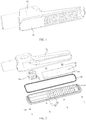
FIG. 1 is a structure schematic diagram of a lighting fixture disclosed in an embodiment of the present application; -
FIG. 2 is an exploded view of the lighting fixture disclosed in an embodiment of the present application; -
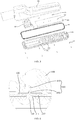
FIG. 3 is a partial sectional view of the structure as shown inFIG. 2 ; -
FIG. 4 is a structure schematic diagram of an elastic clip of the lighting fixture disclosed in an embodiment of the present application; -
FIG. 5 is an exploded view of a lighting fixture disclosed in another embodiment of the present application; -
FIG. 6 is a partial sectional view of the structure as shown inFIG. 5 ; -
FIG. 7 is a structure schematic diagram of an elastic clamping member in the structure as shown inFIG. 5 ; -
FIG. 8 is a partial sectional view of the lighting fixture disclosed in an embodiment of the present application; and -
FIG. 9 is a structure schematic diagram of a vent hole of the lighting fixture disclosed in an embodiment of the present application. - 100-housing, 110-accommodating groove, 111-top wall, 120-limiting groove, 130-sealing rib, 200-light source assembly, 210-light source panel, 211-connection through-hole, 300-lens cover, 310-cover body, 320-lens unit, 330-second sealing groove, 340-vent hole, 400-anti-deformation assembly, 410-connection rib, 411-connection portion, 412-fastening portion, 412a-fastening surface, 412b-V-shaped guide surface, 420-elastic clip, 421-strip body portion, 422-first snap-fit portion, 423-second snap-fit portion, 430-elastic clamping member, 431-mounting piece, 432-first clamping piece, 433-second clamping piece, 500-driver, 600-seal, 610-first sealing groove, 620-first sealing protrusion, 630-second sealing protrusion, and 700-threaded fastener.
- To make the objects, technical solutions and advantages of the present application clearer, the technical solutions of the present application will be clearly and completely described below in conjunction with specific embodiments and corresponding accompanying drawings of the present application. Obviously, the described embodiments are merely a part of the embodiments of the present application, rather than all the embodiments. Based on the embodiments of the present application, all other embodiments obtained by those of ordinary skill in the art without creative effort belong to the protection scope of the present application.
- The technical solutions disclosed in various embodiments of the present application will be described below in detail with reference to the accompanying drawings.
- As shown in
FIG. 1 to FIG. 9 , an embodiment of the present application discloses a lighting fixture that may be a street lamp, including ahousing 100, alight source assembly 200, alens cover 300, ananti-deformation assembly 400, and adriver 500. Thehousing 100 and thelens cover 300 are connected and form a mounting space, specifically, thehousing 100 and thelens cover 300 may be connected through threadedfasteners 700, thereby facilitating disassembly and maintenance of the lighting fixture. Thelight source assembly 200 is mounted in the mounting space and specifically includes alight source panel 210 and a light-emitting unit (not shown in the figures) arranged on thelight source panel 210, and thelight source panel 210 is provided with a connection through-hole 211. Thelens cover 300 includes acover body 310 and alens unit 320 arranged on thecover body 310, thelens unit 320 may cover the light-emitting unit, and light from the light-emitting unit is emitted through thelens unit 320. A part of theanti-deformation assembly 400 is located in the connection through-hole 211, and theanti-deformation assembly 400 is connected to thelens unit 320 to apply an action force to thelens unit 320 to enable the lens unit to fit thelight source panel 210. Thedriver 500 may be mounted in the mounting space mentioned above, and is electrically connected to thelight source panel 210 to drive the light-emitting unit to emit light. - By adopting the above structure, when the
light source panel 210 or thelens unit 320 trends to deform under the heat, relative positions of thelens unit 320 and thelight source panel 210 are not easy to change due to an effect of theanti-deformation assembly 400; thus, deformations of thelight source panel 210 and thelens unit 320 may be limited, to enable a relative position relationship between the components, such as the light-emitting units and the lens unit, to be more stable, thereby improving the lighting effects of the lighting fixture. - As shown in
FIG. 2 to FIG. 4 , in an embodiment, theanti-deformation assembly 400 includes aconnection rib 410 and anelastic clip 420. One end of theconnection rib 410 is connected to thelens unit 320, and the other end of theconnection rib 410 penetrates the connection through-hole 211, and is in snap-fit with theelastic clip 420. In order to improve a connection strength of theanti-deformation assembly 400 and thelens unit 320, theconnection rib 410 may be integrally formed with thelens unit 320. After theconnection rib 410 and theelastic clip 420 are in snap fit correspondingly, theelastic clip 420 is abutted against thelight source panel 210 so that the position of theelastic clip 420 relative to thelight source panel 210 is limited to further limit the position of theconnection rib 410, so as to apply an action force to thelens unit 320 to enable thelens unit 320 to fit thelight source panel 210. In such an embodiment, the connection between theconnection rib 410 and theelastic clip 420 is reliable, thereby resulting in a more reliable fitting between thelens unit 320 and thelight source panel 210. - Specifically, the
housing 100 may be provided with anaccommodating groove 110, theelastic clip 420 is located in theaccommodating groove 110, correspondingly, so that the structure of the lighting fixture is more compact. Besides, in the matching process of theconnection rib 410 and theelastic clip 420, theaccommodating groove 110 may assist in limiting the position of theelastic clip 420 to achieve the more reliable matching between theconnection rib 410 and theelastic clip 420. - Alternatively, the
elastic clip 420 includes astrip body portion 421, a first snap-fit portion 422, and a second snap-fit portion 423, the first snap-fit portion 422 and the second snap-fit portion 423 are respectively arranged at two ends of thestrip body portion 421; the first snap-fit portion 422 and the second snap-fit portion 423 are in opposite arrangement to form a snap-fit gap therebetween; theconnection rib 410 is locked in the snap-fit gap; and both a joint between thestrip body portion 421 and the first snap-fit portion 422 and a joint between thestrip body portion 421 and the second snap-fit portion 423 are abutted against thelight source panel 210. As thestrip body portion 421 has a certain elasticity, the first snap-fit portion 422 and the second snap-fit portion 423 may deform appropriately to allow theconnection rib 410 to be locked in the snap-fit gap easily, in a process of locking theconnection rib 410 in the snap-fit gap. After theconnection rib 410 is locked in place, the first snap-fit portion 422 and the second snap-fit 423 are reset, to reliably prevent theconnection rib 410 from releasing from the snap-fit gap. In addition, because abutting portions of theelastic clip 420 and thelight source panel 210 are distributed on two opposite sides of theconnection rib 410, theelastic clip 420 has a high stability in position relative to thelight source panel 210, thereby effectively overcoming an action force generated by reasons, such as heating of the components, to guarantee the lighting effects of the lighting fixture. - To facilitate operators to connect the
connection rib 410 and theelastic clip 420 together, theconnection rib 410 includes aconnection portion 411 and afastening portion 412. Thefastening portion 412 is connected to thelens unit 320 through theconnection portion 411, and has afastening surface 412a protruding relative to theconnection portion 411 and a V-shaped guide surface 412b connected to thefastening surface 412. Thefastening surface 412a is abutted against the first snap-fit portion 422 and the second snap-fit portion 423, and the V-shaped guide surface 412b is located at a side, away from thelight source panel 210, of thefastening surface 412a. In the process of locking theconnection rib 410 in the corresponding snap-fit gap, the V-shaped guide surface 412b is in slide fit with the first snap-fit portion 422 and the second snap-fit portion 423. Because a dimension of a part of the V-shaped guide surface 412b matched with the first snap-fit portion 422 and the second snap-fit portion 423 is small, the first snap-fit portion 422 and the second snap-fit portion 423 are easy to be opened. In addition, a bonding force between the first snap-fit portion 422 and the second snap-fit portion 423 is high, which improves a snap-fit reliability to a certain degree. - The structure of the edge of the first snap-
fit portion 422 and the structure of the edge of the second snap-fit portion 423 may be flexibly arranged. In order to expand an action area between the first snap-fit portion 422 and the second snap-fit portion 423 and thefastening portion 412, to improve the connection strength, the edge of the first snap-fit portion 422 and the edge of the second snap-fit portion 423 are set as strip edges, while thefastening surface 412a is set as a strip surface that extends along a direction parallel to extension directions of the strip edges. - Alternatively, a lateral dimension of the snap-fit gap mentioned above is gradually reduced in a direction gradually away from the
light source panel 210. It should be noted that the lateral direction is parallel to a direction in which the first snap-fit portion 422 and the second snap-fit portion 423 face each other. With the arrangement, the matching between the first snap-fit portion 422 and the second snap-fit portion 423 and thefastening portion 412 is much smooth, to facilitate an assembling operation of the lighting fixture. - In order to simplify the structure of the
elastic clip 420, both the first snap-fit portion 422 and the second snap-fit portion 423 may be of plate structures, which form a V-shaped structure. - In addition, to simplify the structure of the
elastic clip 420, thestrip body portion 421 may be of a U-shaped structure. The first snap-fit portion 422 and the second snap-fit portion 423 may be located inside the strip body portion421. Further, eachaccommodating groove 110 has atop wall 111 facing thelight source panel 210; thetop wall 111 may be of a planer structure; and a top of thestrip body portion 421 is abutted against thetop wall 111. In such a structure, an abutting area between theelastic clip 420 and thehousing 100 is large, and thehousing 100 may assist in limiting a deformation amplitude of theelastic clip 420, to prevent theelastic clip 420 from being separated from thecorresponding connection rib 410 due to excessive deformation after being stressed. - As shown in
FIG. 5 to FIG. 7 , in another embodiment, the anti-deformation assembly further includes aconnection rib 410 and anelastic clamping member 430. Theelastic clamping member 430 has a clamping gap. One end of theconnection rib 410 is connected to thelens unit 320, the other end of theconnection rib 410 penetrates the connection through-hole 211, and is inserted into the clamping gap. Theelastic clamping member 430 is abutted against thelight source panel 210, and applies a clamping force to theconnection rib 410. Also, theanti-deformation assembly 400 and theconnection rib 410 keep connected by a frictional force therebetween. The connection mode may meet requirements for the connection strength on one hand, and on the other hand, may simplify the structure of theanti-deformation assembly 400. - Further, in order to prevent the
elastic clamping member 430 from moving along a direction away from thelight source panel 210 during a process of inserting theconnection rib 410 into the clamping gap, a limitinggroove 120 may be formed in thehousing 100, and at least a part of theelastic clamping member 430 is located in the limitinggroove 120. When theelastic clamping member 430 has a moving trend mentioned above, an inner surface of the limitinggroove 120 may prevent theelastic clamping member 430 moving, thereby allowing theconnection rib 410 to be reliably inserted into the clamping gap. - In the embodiment of the present application, the
elastic clamping member 430 may include a mountingpiece 431, and afirst clamping piece 432 and asecond clamping piece 433 which are arranged on the mountingpiece 431. The mountingpiece 431 is abutted against thelight source panel 210, both thefirst clamping piece 432 and thesecond clamping piece 433 protrude towards a direction away from thelight source panel 210 relative to the mountingpiece 431, and the clamping gap is formed between thefirst clamping piece 432 and thesecond clamping piece 433. Thefirst clamping piece 432 and thesecond clamping piece 433 have a certain elasticity; in a process of inserting theconnection rib 410 into the clamping gap, theconnection rib 410 applies the enough action force to thefirst clamping piece 432 and thesecond clamping piece 433 to deform them, so that theconnection rib 410 may be inserted into the clamping gap therebetween. Thefirst clamping piece 432 and thesecond clamping piece 433 deform to apply reaction forces to theconnection rib 410 to increase a frictional force between the two clamping pieces and theconnection rib 410, thereby achieving an effect of improving a reliability in connection. - An amount of the
first clamping piece 432 and thesecond clamping piece 433 may be one, and abutting positions of thefirst clamping piece 432 and thesecond clamping piece 433 and theconnection rib 410 are opposite to a thickness direction of theconnection rib 410, thereby applying an effective action force. To further increase the action force, the amount of at least one of the group consisting of thefirst clamping piece 432 and thesecond clamping piece 433 may be multiple; thus, a clamping force formed between thefirst clamping piece 432 and thesecond clamping piece 433 and theconnection rib 410 may be increased by increasing joint points. - To further improve the clamping force formed between the
first clamping piece 432 and thesecond clamping piece 433 and theconnection rib 410, thefirst clamping piece 432 and thesecond clamping piece 433 may be in staggered arrangement. As shown inFIG. 7 , taking the arrangement of twofirst clamping pieces 432 and onesecond clamping piece 433 as an example, thesecond clamping piece 433 is arranged in a gap between the twofirst clamping pieces 432, thereby achieving a structural form in staggered arrangement. - Alternatively, a lateral dimension of the clamping gap is gradually reduced in a direction gradually away from the
light source panel 210. It should be noted that the lateral direction is parallel to the direction in which thefirst clamping piece 432 and thesecond clamping piece 433 face each other. With the arrangement, the matching between thefirst clamping piece 432 and thesecond clamping piece 433, and theconnection rib 410 is much smooth, to facilitate an assembling operation of the lighting fixture. - To guarantee an airtightness of the lighting fixture, a
seal 600 may be arranged between thehousing 100 and thelens cover 300. As shown inFIG. 8 , theseal 600 has afirst sealing groove 610, and afirst sealing protrusion 620 is provided on a wall of thefirst sealing groove 610; thehousing 100 is provided with a sealingrib 130 that is inserted into thefirst sealing groove 610, and a surface of the sealingrib 130 is abutted against thefirst sealing protrusion 620. With the arrangement of thefirst sealing protrusion 620, in a process of inserting the sealingrib 130 into thefirst sealing groove 610, the sealingrib 130 applies an action force to thefirst sealing protrusion 620 to deform thefirst sealing protrusion 620, so that a high pressing force is formed between the sealingrib 130 and thefirst sealing protrusion 620, and the airtightness therebetween is improved. - Similarly, the
lens cover 300 has asecond sealing groove 330. Theseal 600 is arranged in thesecond sealing groove 330. Asecond sealing protrusion 630 is arranged on an outer surface of theseal 600, and is abutted against a wall of thesecond sealing groove 330. In the process of inserting the sealingrib 130 into thefirst sealing groove 610, the sealingrib 130 pushes theseal 600, thesecond sealing protrusion 630 is pressed to the wall of thesecond sealing groove 330, and a close fit between thesecond sealing protrusion 630 and thesecond sealing groove 330 may be achieved, thereby improving the airtightness of the lighting fixture. - To further improve a sealing effect, the amount of at least one of the group consisting of the
first sealing protrusion 620 and thesecond sealing protrusion 630 may be multiple. The multiple first sealingprotrusions 620 and/or the multiple second sealingprotrusions 630 are arranged along an extension direction of the sealingrib 130. - In the case of assembling of the lighting fixture, there is air in the
second sealing groove 330, after air in thesecond sealing groove 330 is quickly exhausted, theseal 600 may be quickly assembled, while the airtightness between theseal 600 and thelens cover 300 may be guaranteed. Thus, as shown inFIG. 9 , avent hole 340, running through to a top edge of thesecond sealing groove 330, may be formed in the wall of thesecond sealing groove 330. Air in thesecond sealing groove 330 may be exhausted through thevent hole 340. A size of thevent hole 340 should not be too large or too small; if the size is too large, an adverse effect will be caused on the final sealing effect, and if the size is too small, an exhaust effect will be weakened. - The above embodiments of the present application focus on descriptions of differences among various embodiments. The different optimization features among the various embodiments may be combined to form a more optimal embodiment as long as they are not contradictory. Considering the conciseness in writing, it will not be repeated here.
- The above descriptions are only specific embodiments of the present application and are not intended to limit the present application. Any modification, equivalent replacement, improvement, etc. made within the spirit and principle of the present application shall be included in the protection scope of the present application.
Claims (13)
- A lighting fixture, comprising a housing (100), a light source assembly (200), a lens cover (300), and an anti-deformation assembly (400),
wherein the housing (100) and the lens cover (300) are connected and form a mounting space; the light source assembly (200) is mounted in the mounting space and comprises a light source panel (210), and a connection through-hole (211) is provided in the light source panel (210); the lens cover (300) comprises a cover body (310) and a lens unit (320) on the cover body (310); and a part of the anti-deformation assembly (400) is in the connection through-hole (211), and the anti-deformation assembly (400) is connected to the lens unit (320) to apply an action force to the lens unit (320) to enable the lens unit (320) to fit the light source panel (210). - The lighting fixture according to claim 1, wherein the anti-deformation assembly (400) comprises a connection rib (410) and an elastic clip (420); one end of the connection rib (410) is connected to the lens unit (320), and the other end of the connection rib (410) penetrates the connection through-hole (211) and is in snap fit with the elastic clip (420); and the elastic clip (420) is abutted against the light source panel (210).
- The lighting fixture according to claim 2, wherein the elastic clip (420) comprises a strip body portion (421), and a first snap-fit portion (422) and a second snap-fit portion (423) which are respectively at two ends of the strip body portion (421); the first snap-fit portion (422) and the second snap-fit portion (423) are opposite to each other to form a snap-fit gap therebetween; the connection rib (410) is locked in the snap-fit gap; and both a joint between the strip body portion (421) and the first snap-fit portion (422) and a joint between the strip body portion (421) and the second snap-fit portion (423) are abutted against the light source panel (210).
- The lighting fixture according to claim 3, wherein the connection rib (410) comprises a connection portion (411) and a fastening portion (412); the fastening portion (412) is connected to the lens unit (320) through the connection portion (411), and has a fastening surface (412a) protruding relative to the connection portion (411) and a V-shaped guide surface (412b) connected to the fastening surface (412a); the fastening surface (412a) is abutted against the first snap-fit portion (422) and the second snap-fit portion (423); and the V-shaped guide surface (412b) is on a side, away from the light source panel (210), of the fastening surface (412a).
- The lighting fixture according to claim 3, wherein a lateral dimension of the snap-fit gap is gradually reduced in a direction gradually away from the light source panel (210), and the lateral direction is parallel to a direction in which the first snap-fit portion (422) and the second snap-fit portion (423) face each other.
- The lighting fixture according to claim 3, wherein the strip body portion (421) is of a U-shaped structure.
- The lighting fixture according to claim 2, wherein the anti-deformation assembly (400) further comprises a connection rib (410) and an elastic clamping member (430); the elastic clamping member (430) comprises a clamping gap; one end of the connection rib (410) is connected to the lens unit (320), and the other end of the connection rib (410) penetrates the connection through-hole (211) and is inserted into the clamping gap; and the elastic clamping member (430) is abutted against the light source panel (210) and applies a clamping force to the connection rib (410).
- The lighting fixture according to claim 7, wherein the elastic clamping member (430) comprises a mounting piece (431), and a first clamping piece (432) and a second clamping piece (433) provided on the mounting piece (431); the mounting piece (431) is abutted against the light source panel (210); both the first clamping piece (432) and the second clamping piece (433) protrude towards a direction away from the light source panel (210) relative to the mounting piece (431); and the clamping gap is formed between the first clamping piece (432) and the second clamping piece (433).
- The lighting fixture according to claim 8, wherein an amount of at least one of the group consisting of the first clamping piece (432) and the second clamping piece (433) is multiple.
- The lighting fixture according to claim 9, wherein the first clamping piece (432) and the second clamping piece (433) are in staggered arrangement.
- The lighting fixture according to claim 8, wherein a lateral dimension of the clamping gap is gradually reduced in a direction gradually away from the light source panel (210), and the lateral direction is parallel to a direction in which the first clamping piece (432) and the second clamping piece (433) face each other.
- The lighting fixture according to any one of claims 1 to 11, wherein a seal (600) is between the housing (100) and the lens cover (300); the lens cover (300) is provided with a second sealing groove (330), the seal (600) is in the second sealing groove (330), and a vent hole (340) is in a wall of the second sealing groove (330), and runs through to a top edge of the second sealing groove (330).
- The lighting fixture according to any one of claims 1 to 11, wherein the lighting fixture comprises a street lamp.
Applications Claiming Priority (2)
| Application Number | Priority Date | Filing Date | Title |
|---|---|---|---|
| CN201822118050.6U CN209012945U (en) | 2018-12-17 | 2018-12-17 | Illuminator |
| PCT/CN2019/126053 WO2020125641A1 (en) | 2018-12-17 | 2019-12-17 | Illuminating lighting fixture |
Publications (2)
| Publication Number | Publication Date |
|---|---|
| EP3798505A1 true EP3798505A1 (en) | 2021-03-31 |
| EP3798505A4 EP3798505A4 (en) | 2021-10-20 |
Family
ID=66843923
Family Applications (1)
| Application Number | Title | Priority Date | Filing Date |
|---|---|---|---|
| EP19898802.4A Pending EP3798505A4 (en) | 2018-12-17 | 2019-12-17 | LIGHTING DEVICE |
Country Status (4)
| Country | Link |
|---|---|
| US (1) | US11262050B2 (en) |
| EP (1) | EP3798505A4 (en) |
| CN (1) | CN209012945U (en) |
| WO (1) | WO2020125641A1 (en) |
Families Citing this family (3)
| Publication number | Priority date | Publication date | Assignee | Title |
|---|---|---|---|---|
| CN209012945U (en) * | 2018-12-17 | 2019-06-21 | 欧普照明股份有限公司 | Illuminator |
| CN210891503U (en) * | 2019-12-16 | 2020-06-30 | 欧普照明股份有限公司 | lamps |
| GB2633391A (en) * | 2023-09-08 | 2025-03-12 | Thorpe F W Plc | A luminaire for exterior lighting |
Family Cites Families (19)
| Publication number | Priority date | Publication date | Assignee | Title |
|---|---|---|---|---|
| US4158222A (en) * | 1977-09-26 | 1979-06-12 | Gulf & Western Industries, Inc. | Limited visibility signal device |
| TWI293702B (en) * | 2005-03-17 | 2008-02-21 | Au Optronics Corp | Backlight modules |
| TWM366024U (en) * | 2009-04-03 | 2009-10-01 | Genius Electronic Optical Co Ltd | Lamp holder having heat-dissipation fins |
| JP5409217B2 (en) * | 2009-09-07 | 2014-02-05 | 株式会社小糸製作所 | Vehicle lighting |
| DE102009049016A1 (en) * | 2009-10-10 | 2011-04-14 | Hella Kgaa Hueck & Co. | Lighting unit for vehicles |
| US8419217B2 (en) * | 2011-01-21 | 2013-04-16 | Hergy Lighting Technology Corp. | LED lamp |
| US20120300456A1 (en) * | 2011-05-26 | 2012-11-29 | Phillips Iii William E | Reflectors optimized for led lighting fixture |
| KR101310365B1 (en) * | 2012-03-16 | 2013-09-23 | 주식회사 포스코엘이디 | Light emitting module and illuminating apparatus comprising the same |
| TWM448626U (en) * | 2012-10-26 | 2013-03-11 | Jin-Sheng Wang | Integrated LED lamp tray |
| WO2014153754A1 (en) * | 2013-03-28 | 2014-10-02 | 东莞华明灯具有限公司 | Connecting device for lamps |
| US9464778B2 (en) * | 2014-01-21 | 2016-10-11 | Cree, Inc. | Lighting device utilizing a double fresnel lens |
| RS56061B1 (en) * | 2015-01-26 | 2017-10-31 | Schreder | IMPROVEMENTS IN OR RELATING TO LENS LEVELS |
| DE202016102265U1 (en) * | 2016-04-28 | 2017-07-31 | Zumtobel Lighting Gmbh | Fastener for connection between an LED board and a luminaire component |
| CN106224905A (en) * | 2016-08-24 | 2016-12-14 | 厦门兴恒隆股份有限公司 | A kind of light source module that can freely convert light illumination mode |
| CN206191529U (en) * | 2016-10-27 | 2017-05-24 | 绍兴康赛浦照明电器有限公司 | A electricity is connected from locking -type structure for LED light |
| CN206449529U (en) * | 2016-11-01 | 2017-08-29 | 深圳市利思达光电科技有限公司 | A kind of high-cooling property flying saucer bulkhead lamp |
| CN207146077U (en) * | 2017-05-25 | 2018-03-27 | 欧普照明股份有限公司 | A kind of light fixture |
| US10704765B2 (en) * | 2018-04-30 | 2020-07-07 | Honeywell International Inc. | Composite optical element |
| CN209012945U (en) * | 2018-12-17 | 2019-06-21 | 欧普照明股份有限公司 | Illuminator |
-
2018
- 2018-12-17 CN CN201822118050.6U patent/CN209012945U/en not_active Expired - Fee Related
-
2019
- 2019-12-17 WO PCT/CN2019/126053 patent/WO2020125641A1/en not_active Ceased
- 2019-12-17 EP EP19898802.4A patent/EP3798505A4/en active Pending
-
2020
- 2020-12-29 US US17/136,599 patent/US11262050B2/en active Active
Also Published As
| Publication number | Publication date |
|---|---|
| CN209012945U (en) | 2019-06-21 |
| WO2020125641A1 (en) | 2020-06-25 |
| US11262050B2 (en) | 2022-03-01 |
| EP3798505A4 (en) | 2021-10-20 |
| US20210116105A1 (en) | 2021-04-22 |
Similar Documents
| Publication | Publication Date | Title |
|---|---|---|
| EP3798505A1 (en) | Illuminating lighting fixture | |
| US10935230B2 (en) | Luminaire | |
| CN211853591U (en) | Lamp fitting | |
| CN111998273A (en) | Downlight body and downlight | |
| US10073216B2 (en) | LED panel light | |
| CN212226844U (en) | Down lamp body and down lamp | |
| JP5630885B1 (en) | lighting equipment | |
| CN211738708U (en) | A LED strip light | |
| CN211853884U (en) | Lamp fitting | |
| CN205956935U (en) | LED line lamp | |
| KR20250080682A (en) | Fixing devicel for lighting lamp and lighting apparatus using the same | |
| KR20120004628U (en) | Indirect lighting device using luminescent diode | |
| CN223076807U (en) | Spotlight line lamp | |
| CN210891232U (en) | lighting fixtures | |
| CN220287218U (en) | Car light PCB joint structure | |
| CN210532308U (en) | Mounting assembly applied to lamp and lamp thereof | |
| TWM586334U (en) | Recessed lamp assembly structure | |
| CN219607021U (en) | Waterproof panel light | |
| CN224003624U (en) | Lampshade and lighting lamp with same | |
| KR200497864Y1 (en) | Assembly for lighing device of ceiling | |
| CN219063260U (en) | Lamp adhesive tape and lamp | |
| CN220601364U (en) | Profile lamp | |
| CN212390152U (en) | Direct type lamp panel lamp | |
| CN205299227U (en) | Light -emitting diode (LED) panel lamp | |
| CN217899658U (en) | Floodlight and lighting system |
Legal Events
| Date | Code | Title | Description |
|---|---|---|---|
| STAA | Information on the status of an ep patent application or granted ep patent |
Free format text: STATUS: THE INTERNATIONAL PUBLICATION HAS BEEN MADE |
|
| PUAI | Public reference made under article 153(3) epc to a published international application that has entered the european phase |
Free format text: ORIGINAL CODE: 0009012 |
|
| STAA | Information on the status of an ep patent application or granted ep patent |
Free format text: STATUS: REQUEST FOR EXAMINATION WAS MADE |
|
| 17P | Request for examination filed |
Effective date: 20201222 |
|
| AK | Designated contracting states |
Kind code of ref document: A1 Designated state(s): AL AT BE BG CH CY CZ DE DK EE ES FI FR GB GR HR HU IE IS IT LI LT LU LV MC MK MT NL NO PL PT RO RS SE SI SK SM TR |
|
| AX | Request for extension of the european patent |
Extension state: BA ME |
|
| A4 | Supplementary search report drawn up and despatched |
Effective date: 20210916 |
|
| RIC1 | Information provided on ipc code assigned before grant |
Ipc: F21Y 115/10 20160101ALN20210910BHEP Ipc: F21Y 105/16 20160101ALN20210910BHEP Ipc: F21W 131/103 20060101ALN20210910BHEP Ipc: F21V 31/00 20060101ALN20210910BHEP Ipc: F21V 5/00 20180101ALI20210910BHEP Ipc: F21V 31/03 20060101ALI20210910BHEP Ipc: F21V 3/00 20150101ALI20210910BHEP Ipc: F21V 17/16 20060101ALI20210910BHEP Ipc: F21S 8/00 20060101AFI20210910BHEP |
|
| DAV | Request for validation of the european patent (deleted) | ||
| DAX | Request for extension of the european patent (deleted) | ||
| STAA | Information on the status of an ep patent application or granted ep patent |
Free format text: STATUS: EXAMINATION IS IN PROGRESS |
|
| 17Q | First examination report despatched |
Effective date: 20230616 |
|
| GRAP | Despatch of communication of intention to grant a patent |
Free format text: ORIGINAL CODE: EPIDOSNIGR1 |
|
| RIC1 | Information provided on ipc code assigned before grant |
Ipc: F21S 8/00 20060101AFI20260212BHEP Ipc: F21V 17/16 20060101ALI20260212BHEP Ipc: F21V 3/00 20150101ALI20260212BHEP Ipc: F21V 31/03 20060101ALI20260212BHEP Ipc: F21V 5/00 20180101ALI20260212BHEP Ipc: F21V 31/00 20060101ALN20260212BHEP Ipc: F21W 131/103 20060101ALN20260212BHEP Ipc: F21Y 105/16 20160101ALN20260212BHEP Ipc: F21Y 115/10 20160101ALN20260212BHEP |
|
| STAA | Information on the status of an ep patent application or granted ep patent |
Free format text: STATUS: GRANT OF PATENT IS INTENDED |
|
| GRAS | Grant fee paid |
Free format text: ORIGINAL CODE: EPIDOSNIGR3 |
|
| INTG | Intention to grant announced |
Effective date: 20260318 |