EP3798504A1 - Rail light - Google Patents
Rail light Download PDFInfo
- Publication number
- EP3798504A1 EP3798504A1 EP19840257.0A EP19840257A EP3798504A1 EP 3798504 A1 EP3798504 A1 EP 3798504A1 EP 19840257 A EP19840257 A EP 19840257A EP 3798504 A1 EP3798504 A1 EP 3798504A1
- Authority
- EP
- European Patent Office
- Prior art keywords
- conductive
- terminal
- elastic
- track
- cable
- Prior art date
- Legal status (The legal status is an assumption and is not a legal conclusion. Google has not performed a legal analysis and makes no representation as to the accuracy of the status listed.)
- Granted
Links
Images



Classifications
-
- F—MECHANICAL ENGINEERING; LIGHTING; HEATING; WEAPONS; BLASTING
- F21—LIGHTING
- F21S—NON-PORTABLE LIGHTING DEVICES; SYSTEMS THEREOF; VEHICLE LIGHTING DEVICES SPECIALLY ADAPTED FOR VEHICLE EXTERIORS
- F21S8/00—Lighting devices intended for fixed installation
- F21S8/03—Lighting devices intended for fixed installation of surface-mounted type
- F21S8/038—Lighting devices intended for fixed installation of surface-mounted type intended to be mounted on a light track
-
- F—MECHANICAL ENGINEERING; LIGHTING; HEATING; WEAPONS; BLASTING
- F21—LIGHTING
- F21S—NON-PORTABLE LIGHTING DEVICES; SYSTEMS THEREOF; VEHICLE LIGHTING DEVICES SPECIALLY ADAPTED FOR VEHICLE EXTERIORS
- F21S8/00—Lighting devices intended for fixed installation
- F21S8/04—Lighting devices intended for fixed installation intended only for mounting on a ceiling or the like overhead structures
- F21S8/06—Lighting devices intended for fixed installation intended only for mounting on a ceiling or the like overhead structures by suspension
- F21S8/066—Lighting devices intended for fixed installation intended only for mounting on a ceiling or the like overhead structures by suspension from a light track
-
- F—MECHANICAL ENGINEERING; LIGHTING; HEATING; WEAPONS; BLASTING
- F21—LIGHTING
- F21V—FUNCTIONAL FEATURES OR DETAILS OF LIGHTING DEVICES OR SYSTEMS THEREOF; STRUCTURAL COMBINATIONS OF LIGHTING DEVICES WITH OTHER ARTICLES, NOT OTHERWISE PROVIDED FOR
- F21V21/00—Supporting, suspending, or attaching arrangements for lighting devices; Hand grips
- F21V21/08—Devices for easy attachment to any desired place, e.g. clip, clamp, magnet
- F21V21/088—Clips; Clamps
-
- F—MECHANICAL ENGINEERING; LIGHTING; HEATING; WEAPONS; BLASTING
- F21—LIGHTING
- F21V—FUNCTIONAL FEATURES OR DETAILS OF LIGHTING DEVICES OR SYSTEMS THEREOF; STRUCTURAL COMBINATIONS OF LIGHTING DEVICES WITH OTHER ARTICLES, NOT OTHERWISE PROVIDED FOR
- F21V21/00—Supporting, suspending, or attaching arrangements for lighting devices; Hand grips
- F21V21/08—Devices for easy attachment to any desired place, e.g. clip, clamp, magnet
- F21V21/096—Magnetic devices
-
- F—MECHANICAL ENGINEERING; LIGHTING; HEATING; WEAPONS; BLASTING
- F21—LIGHTING
- F21V—FUNCTIONAL FEATURES OR DETAILS OF LIGHTING DEVICES OR SYSTEMS THEREOF; STRUCTURAL COMBINATIONS OF LIGHTING DEVICES WITH OTHER ARTICLES, NOT OTHERWISE PROVIDED FOR
- F21V21/00—Supporting, suspending, or attaching arrangements for lighting devices; Hand grips
- F21V21/34—Supporting elements displaceable along a guiding element
- F21V21/35—Supporting elements displaceable along a guiding element with direct electrical contact between the supporting element and electric conductors running along the guiding element
-
- F—MECHANICAL ENGINEERING; LIGHTING; HEATING; WEAPONS; BLASTING
- F21—LIGHTING
- F21V—FUNCTIONAL FEATURES OR DETAILS OF LIGHTING DEVICES OR SYSTEMS THEREOF; STRUCTURAL COMBINATIONS OF LIGHTING DEVICES WITH OTHER ARTICLES, NOT OTHERWISE PROVIDED FOR
- F21V23/00—Arrangement of electric circuit elements in or on lighting devices
- F21V23/001—Arrangement of electric circuit elements in or on lighting devices the elements being electrical wires or cables
- F21V23/002—Arrangements of cables or conductors inside a lighting device, e.g. means for guiding along parts of the housing or in a pivoting arm
-
- F—MECHANICAL ENGINEERING; LIGHTING; HEATING; WEAPONS; BLASTING
- F21—LIGHTING
- F21V—FUNCTIONAL FEATURES OR DETAILS OF LIGHTING DEVICES OR SYSTEMS THEREOF; STRUCTURAL COMBINATIONS OF LIGHTING DEVICES WITH OTHER ARTICLES, NOT OTHERWISE PROVIDED FOR
- F21V23/00—Arrangement of electric circuit elements in or on lighting devices
- F21V23/003—Arrangement of electric circuit elements in or on lighting devices the elements being electronics drivers or controllers for operating the light source, e.g. for a LED array
-
- F—MECHANICAL ENGINEERING; LIGHTING; HEATING; WEAPONS; BLASTING
- F21—LIGHTING
- F21V—FUNCTIONAL FEATURES OR DETAILS OF LIGHTING DEVICES OR SYSTEMS THEREOF; STRUCTURAL COMBINATIONS OF LIGHTING DEVICES WITH OTHER ARTICLES, NOT OTHERWISE PROVIDED FOR
- F21V23/00—Arrangement of electric circuit elements in or on lighting devices
- F21V23/06—Arrangement of electric circuit elements in or on lighting devices the elements being coupling devices, e.g. connectors
-
- F—MECHANICAL ENGINEERING; LIGHTING; HEATING; WEAPONS; BLASTING
- F21—LIGHTING
- F21V—FUNCTIONAL FEATURES OR DETAILS OF LIGHTING DEVICES OR SYSTEMS THEREOF; STRUCTURAL COMBINATIONS OF LIGHTING DEVICES WITH OTHER ARTICLES, NOT OTHERWISE PROVIDED FOR
- F21V17/00—Fastening of component parts of lighting devices, e.g. shades, globes, refractors, reflectors, filters, screens, grids or protective cages
- F21V17/10—Fastening of component parts of lighting devices, e.g. shades, globes, refractors, reflectors, filters, screens, grids or protective cages characterised by specific fastening means or way of fastening
- F21V17/105—Fastening of component parts of lighting devices, e.g. shades, globes, refractors, reflectors, filters, screens, grids or protective cages characterised by specific fastening means or way of fastening using magnets
-
- F—MECHANICAL ENGINEERING; LIGHTING; HEATING; WEAPONS; BLASTING
- F21—LIGHTING
- F21V—FUNCTIONAL FEATURES OR DETAILS OF LIGHTING DEVICES OR SYSTEMS THEREOF; STRUCTURAL COMBINATIONS OF LIGHTING DEVICES WITH OTHER ARTICLES, NOT OTHERWISE PROVIDED FOR
- F21V19/00—Fastening of light sources or lamp holders
- F21V19/001—Fastening of light sources or lamp holders the light sources being semiconductors devices, e.g. LEDs
- F21V19/003—Fastening of light source holders, e.g. of circuit boards or substrates holding light sources
- F21V19/0035—Fastening of light source holders, e.g. of circuit boards or substrates holding light sources the fastening means being capable of simultaneously attaching of an other part, e.g. a housing portion or an optical component
Definitions
- the present application relates to a technical field of lighting, in particular, to a track light.
- the track light in the prior art mainly aims at satisfying the convenience of mechanical installation, but is relatively complicated in structure in terms of electric connection and particularly a structure of electric connection between the driving power source and a track, and therefore, relatively long time is spent on assembly.
- Embodiments of the present application provide a track light to solve the above problems.
- the accommodating cavity comprises a cavity bottom opposite to the connection opening in the thickness direction and two cavity walls close to the connection opening which are oppositely disposed in the width direction
- the conductive cable is located at a side of the accommodating cavity along the width direction
- the elastic conductive terminal is only capable of being popped out of the driving housing along the width direction.
- the track light further comprises an insulating member fixed in the accommodating cavity, a side of the insulating member facing away from the cavity wall is provided with a cable slot, and the conductive cable is fixed in the cable slot.
- the cable slot and/or the elastic conductive terminal are provided with guide surface(s), when the driving power source is into the accommodating cavity through the connection opening, the elastic conductive terminal is capable of retracting towards an inside of the driving housing under the guide of the guide surface(s), and the elastic conductive terminal is capable of extending into the cable slot along the width direction after crossing the guide surface(s) and is electrically connected with the conductive cable.
- the conductive cable comprises a first conductive cable and a second conductive cable with opposite electric properties, the first conductive cable and the second conductive cable are mutually staggered in the thickness direction, the elastic conductive terminal comprises a first elastic conductive terminal and a second elastic conductive terminal, the first elastic conductive terminal and the second elastic conductive terminal are mutually staggered in the thickness direction, the first elastic conductive terminal is electrically connected with the first conductive cable, and the second elastic conductive terminal is electrically connected with the second conductive cable.
- two of the first conductive cables and two of the second conductive cables are provided, the two of the first conductive cables are oppositely disposed along the width direction, and the two of the second conductive cables are oppositely disposed along the width direction; two of the first elastic conductive terminals and two of the second elastic conductive terminals are provided, the two of the first elastic conductive terminals are disposed back to back along the width direction and are electrically connected with the different first conductive cables respectively, and the two second elastic conductive terminals are disposed back to back along the width direction and are electrically connected with the different second conductive cables respectively.
- a terminal guide slot extending along the width direction is provided inside the driving housing, and the elastic conductive terminal is disposed in the terminal guide slot.
- the elastic conductive terminal comprises a conductive pin, an elastic member and a conductive sheet;
- the conductive pin is configured to extend out of the driving housing and electrically connect with the conductive cable, the conductive pin is further provided with an abutting part, two ends of the elastic member is abutted with the abutting part and the terminal guide slot respectively, and the elastic member applies an acting force to make the conductive pin extend out of the driving housing, the conductive sheet is disposed at a side of the abutting part facing away from the elastic member and abutted with the abutting part when the conductive pin is electrically connected with the conductive cable, and the output terminal is electrically connected with the conductive sheet.
- the conductive sheet is provided with an assembly gap, and the conductive pin extends in through the assembly gap.
- the terminal guide slot is provided with a clamping connection opening, and the conductive sheet is clamped into the clamping connection opening.
- the cavity wall is provided with a first clamping slot, and the insulating member is in clamping connected in the first clamping slot.
- the guide track comprises a first magnetic member fixed on the cavity bottom
- the driving power source comprises a second magnetic member fixed at a side of the power source housing facing away from the output terminal
- the first magnetic member and the second magnetic member are capable of being fixedly connected by magnetic adsorption.
- the cavity bottom is provided with a second clamping slot, and the first magnetic member is fixed in the second clamping slot.
- the first magnetic member is a magnetic metal plate
- the second magnetic member is a magnet
- the light source module further comprises a lens covering the connection opening and in clamping connection with the accommodating cavity, and the light emitting component is fixedly connected with the lens.
- the track light disclosed in the embodiments of the present application is capable of achieving automatic electric connection between an elastic conductive terminal and a conductive cable when the driving power source enters into an accommodating cavity from a connection opening, thereby saving the assembly time.
- An embodiment of the present application discloses a track light, as shown in Fig. 1 to Fig. 6 , including a track 1, a driving power source 2 and a light source module 3.
- the track light is of a strip-shaped structure.
- the track light is defined by adopting a length direction X, a width direction Y and a thickness direction Z in the present embodiment.
- the guide track 1 is used as a basic structure of the track light and is configured for fixing the driving power source 2 and the light source module 3; and meanwhile, the guide track 1 also provides power for the driving power source 2.
- the guide track 1 includes a track housing 10, insulating members 12 and conductive cables 14, which extend in the length direction X.
- the track housing 10 is generally an aluminum extruded housing which is good in appearance, high in structural strength, favorable in molding process and relatively good in overall performances.
- An accommodating cavity 10a is formed by being surrounded by the track housing 10; the accommodating cavity 10a includes a connection opening 100 in the thickness direction Z and a cavity bottom 102 opposite to the connection opening 100; the accommodating cavity 10a further includes two cavity walls 104 adjacent to the connection opening 100 in the width direction Y and oppositely disposed.
- the insulating members 12 are configured for fixing the conductive cables 14 and isolating electric energy to avoid short circuits.
- the insulating members 12 are fixedly disposed in the accommodating cavity 10a; in this case, the insulating members 12 can be fixedly disposed on the cavity bottom 102; the insulating members 12 can also be fixedly disposed on the cavity walls 104.
- the side, facing to the center of the accommodating cavity 10a, of the insulating members 12 are provided with cable slot 120, and the conductive cables 14 are fixedly disposed in the cable slot 120.
- the conductive cable 14 itself is provided with exposed conductive surface extending in the length direction X, and electric energy can be transmitted at any point on the conductive surface.
- the track housing 10 is made of an insulating material; in this case, it is possible that the insulating members 12 are directly fixed on the track housing 10, without provision of the conductive cables 14.
- the driving power source 2 is configured for obtaining electric energy from the guide track and transmit electric energy to the light source module 3.
- the driving power source 2 includes a driving housing 20, elastic conductive terminals 22 and an output terminal 24, and in addition, generally further includes a driving board 28.
- Terminal guide slots 200 can be provided inside the driving housing 20, for guiding the elastic conductive terminals 22; the elastic conductive terminals 22 are disposed in the terminal guide slots 200 and can only be popped out of the driving housing 20 along the terminal guide slots 200. According to different positions of the conductive cables 14, extension directions of the terminal guide slots 200 are different.
- the terminal guide slots 200 are also disposed along the thickness direction Z; and when the conductive cables 14 are disposed at one side of the cavity wall 104 along the width direction Y, the terminal guide slots 200 are also disposed along the width direction Y.
- the driving board 28 is also mounted in the driving housing 20 and is configured for switching and controlling the power source.
- the driving housing 20 in the present embodiment can be divided into two parts, that is, an upper housing 20a and a lower housing 20b; and the two parts are connected by a structure such as a screw and a buckle.
- the light source module 3 generally includes a light emitting component 30 and an input terminal 32; and the light emitting component 30 is electrically connected with the input terminal 32.
- An electric connection process of the light source module 3 can be realized by connecting the input terminal 32 of the light source module 3 to the output terminal 24 after the driving power source 2 is mounted.
- the input terminal 32 and the output terminal 24 can adopt a male and female terminal structure or a pin and elastic metal sheet matched structure and can further adopt various connection structures such as a golden finger connection structure, a pin connection structure and even a welded structure.
- the cable slots 120 and the elastic conductive terminals 22 can be provided with guide surfaces for cooperation.
- the elastic conductive terminals 22 are capable of retracting towards the inside of the driving housing 20 under the guide of the guide surfaces; and the elastic conductive terminals 22, by virtue of its elasticity, can be re-popped out and extend into the cable slots 120 in the width direction Y after crossing the guide surfaces, to electrically connected with the conductive cables 14.
- the process of electric connection between the driving power source 2 and the guide track 1 is very simple, so that the assembly time is greatly shortened.
- the output terminal 24 is disposed at one side of the driving housing 20 in the thickness direction Z and is electrically connected with the elastic conductive terminals 22.
- the elastic conductive terminals 22 and the output terminal 24 are electrically connected with the driving board 25 at the same time.
- the elastic conductive terminals 22 in the present embodiment can include conductive pins 220, elastic members 222 and conductive sheets 224.
- the conductive pins 220 are configured to extend out of the driving housing 10 and are electrically connected with the conductive cables 14.
- the conductive pins 220 are provided with abutting parts 220a.
- the elastic members 222 can adopt various elastic structures such as spring and elastic sheet.
- the conductive sheet 224 is disposed at a side of the abutting part 220a facing away from the elastic member 222, and is abutted with the abutting part 220a when the conductive pin 220 is electrically connected with the conductive cables 14.
- the output terminal 24 can be electrically connected with the conductive sheets 224 so as to achieve a stable electric connection structure.
- the conductive sheets 224 may be provided with assembly gaps 224a, and the conductive pins 220 extend into the assembly gaps 224a, in this way, the conductive sheets 224 can be at least abutted and matched with the abutting parts 220a from two sides of the conductive pin 220; and therefore, the stability of electric connection can be improved.
- the terminal guide slots 200 can be provided with clamping connection openings 200a; and the conductive sheet 224 is in clamping connection with and fixedly disposed in the clamping connection opening 200a.
- two ends of the conductive sheet 224 can also be bent or folded, so that the conductive sheet 224 become into a three-dimensional structure from a sheet to further improve the stability.
- the guide surfaces can be disposed in the cable slots 120 only; for example, edges of clamping hooks of the cable slots 120 are designed to be first guide surfaces 120a which are arc-shaped or obliquely extend.
- the guide surfaces can also be disposed on the elastic conductive terminals 22 only; for example, ends of the conductive pins 220 are designed to be second guide surfaces 220b which are arc-shaped.
- ends of the conductive pins 220 are designed to be second guide surfaces 220b which are arc-shaped.
- the specific shapes of the guide surfaces in the present embodiment are not particularly limited as long as a guide function is achieved.
- a circuit is required to be formed for electric connection; and therefore, two electrodes with opposite electric properties are generally required to be connected at the same time.
- the conductive cables 14 in the present embodiment include first conductive cables 14a and second conductive cables 14b which have opposite electric properties; the first conductive cable 14a and the second conductive cable 14b are required to be mutually staggered in the thickness direction Z; that is, they are different in distance from the connection opening 100.
- the elastic conductive terminals 22 also include first elastic conductive terminals 22a and second elastic conductive terminals 22b; the first elastic conductive terminal 22a and the second elastic conductive terminal 22b can have the identical structure, but are also required to be mutually staggered in the thickness direction Z.
- the first elastic conductive terminals 22a are electrically connected with the first conductive cables 14a
- the second elastic conductive terminals 22b are electrically connected with the second conductive cables 14b, so that a connection circuit is formed.
- two first conductive cables 14a and two second conductive cables 14b can be disposed at the same time in the present embodiment, the two first conductive cables 14a are oppositely disposed in the width direction Y, and the two second conductive cables 14b are also oppositely disposed in the width direction Y.
- the number of the first elastic conductive terminals 22a and the number of the second elastic conductive terminals 22b are both two; the two first elastic conductive terminals 22a are disposed back to back in the width direction Y and are electrically connected with different first conductive cables 14a respectively; the two second elastic conductive terminals 22b are also disposed back to back in the width direction Y and are electrically connected with different second conductive cables 14b respectively.
- Structures for fixing the elastic conductive terminals 22 at two sides can be identical or different as long as there are no substantial influences to electric connection property.
- the elastic conductive terminals 22 can be fixedly disposed by the insulating members 12 respectively disposed at two sides.
- the driving power source 2 can be electrically connected with the two separately disposed elastic conductive terminals 22 at the same time when extending into the accommodating cavity 10a, which is equivalent to that two circuits connected in parallel are formed; therefore, the safety can be increased exponentially.
- the insulating members 12 can be fixed on the cavity walls 104 in a clamping connection way; for example, the walls 104 are provided with first clamping slots 104a, and the insulating members 12 are clamped inside the first clamping slots 104a.
- the cavity bottom 102 of the guide track 1 can be provided with first magnetic members 16. Similar to the way of fixing the insulating members 12, the first magnetic members 16 can be clamped and fixed on the cavity bottom 102 by the second clamping slots 102a provided on the cavity bottom 102. Meanwhile, second magnetic members 26 are provided inside the driving power source 2; the second magnetic members 26 can be fixed at the side of the power source housing 20 facing away from the output terminal 24.
- the first magnetic members 16 and the second magnetic members 26 are capable of generating magnetic adsorption effects so as to be rapidly close to each other and finally fixedly connected together.
- electric connection between each of the elastic conductive terminals 22 and each of the conductive cables 14 can also be automatically completed.
- both the first magnetic members 16 and the second magnetic members 26 can be magnets; however, the cost is relatively high.
- the first magnetic member 16 can adopt magnetic metal plate such as iron plate; and the magnetic metal plate can extend to any position of the guide track 1 in the length direction X; and the second magnetic members 26 adopt magnet such as magnetic stone; and the magnetic metal plate is adsorbed by the magnets.
- the magnetic metal plate is low in price; and therefore, the cost can be effectively reduced.
- the magnets can be fixed on the driving housing 20 by structure such as clamping hook.
- the light source module 3 can adopt a spotlight, a downlight and the like or adopt a linear module; the light source module 3 of linear module generally further includes a lens 34 configured for distributing light for the light emitting component 30.
- structures such as clamping bars 104b can be disposed on the cavity walls 104 to clamp and fix the lens 34; and the lens 34 can cover the connection opening 100 after being fixed.
- the light emitting component 30 can be fixedly connected with the lens 34, so that the structural stability of the light emitting component 30 and the lens 34 is improved.
- the assembly time can be saved.
Landscapes
- Engineering & Computer Science (AREA)
- General Engineering & Computer Science (AREA)
- Microelectronics & Electronic Packaging (AREA)
- Arrangement Of Elements, Cooling, Sealing, Or The Like Of Lighting Devices (AREA)
- Planar Illumination Modules (AREA)
- Non-Portable Lighting Devices Or Systems Thereof (AREA)
Abstract
Description
- The present application relates to a technical field of lighting, in particular, to a track light.
- With the more and more obvious diversity and differentiation of lighting demands of people, the demands of the people have not been satisfied by a track light with a fixed structure, and on this premise, a track light of which a light source module and a driving power source can be arbitrarily regulated on positions appears.
- However, when connecting the light source module and the driving power source, the track light in the prior art mainly aims at satisfying the convenience of mechanical installation, but is relatively complicated in structure in terms of electric connection and particularly a structure of electric connection between the driving power source and a track, and therefore, relatively long time is spent on assembly.
- Embodiments of the present application provide a track light to solve the above problems.
- The embodiment of the present application adopts the following technical solutions:
- An embodiment of the present application provides a track light, with a length direction, a width direction and a thickness direction, characterized in that , the track light comprises a guide track, a driving power source and a light source module;
- the guide track comprises a track housing and a conductive cable extending along the length direction; the track housing comprises an accommodating cavity, the accommodating cavity comprises a connection opening located in the thickness direction, and the conductive cable is fixed in the accommodating cavity;
- the driving power source comprises a driving housing, an elastic conductive terminal and an output terminal, the elastic conductive terminal is capable of being popped out of the driving housing, and the output terminal is disposed at a side of the driving housing and is electrically connected with the elastic conductive terminal;
- the light source module comprises a light emitting component and an input terminal, the light emitting component is electrically connected with the input terminal, and the input terminal is connected with the output terminal;
- when the driving power source and the light source module are into the accommodating cavity through the connection opening, the elastic conductive terminal is capable of being electrically connected with the conductive cable.
- Preferably, in the above described track light, the accommodating cavity comprises a cavity bottom opposite to the connection opening in the thickness direction and two cavity walls close to the connection opening which are oppositely disposed in the width direction, the conductive cable is located at a side of the accommodating cavity along the width direction, and the elastic conductive terminal is only capable of being popped out of the driving housing along the width direction.
- Preferably, in the above described track light, the track light further comprises an insulating member fixed in the accommodating cavity, a side of the insulating member facing away from the cavity wall is provided with a cable slot, and the conductive cable is fixed in the cable slot.
- Preferably, in the above described track light, the cable slot and/or the elastic conductive terminal are provided with guide surface(s), when the driving power source is into the accommodating cavity through the connection opening, the elastic conductive terminal is capable of retracting towards an inside of the driving housing under the guide of the guide surface(s), and the elastic conductive terminal is capable of extending into the cable slot along the width direction after crossing the guide surface(s) and is electrically connected with the conductive cable.
- Preferably, in the above described track light, the conductive cable comprises a first conductive cable and a second conductive cable with opposite electric properties, the first conductive cable and the second conductive cable are mutually staggered in the thickness direction, the elastic conductive terminal comprises a first elastic conductive terminal and a second elastic conductive terminal, the first elastic conductive terminal and the second elastic conductive terminal are mutually staggered in the thickness direction, the first elastic conductive terminal is electrically connected with the first conductive cable, and the second elastic conductive terminal is electrically connected with the second conductive cable.
- Preferably, in the above described track light, two of the first conductive cables and two of the second conductive cables are provided, the two of the first conductive cables are oppositely disposed along the width direction, and the two of the second conductive cables are oppositely disposed along the width direction;
two of the first elastic conductive terminals and two of the second elastic conductive terminals are provided, the two of the first elastic conductive terminals are disposed back to back along the width direction and are electrically connected with the different first conductive cables respectively, and the two second elastic conductive terminals are disposed back to back along the width direction and are electrically connected with the different second conductive cables respectively. - Preferably, in the above described track light, a terminal guide slot extending along the width direction is provided inside the driving housing, and the elastic conductive terminal is disposed in the terminal guide slot.
- Preferably, in the above described track light, the elastic conductive terminal comprises a conductive pin, an elastic member and a conductive sheet; the conductive pin is configured to extend out of the driving housing and electrically connect with the conductive cable, the conductive pin is further provided with an abutting part, two ends of the elastic member is abutted with the abutting part and the terminal guide slot respectively, and the elastic member applies an acting force to make the conductive pin extend out of the driving housing, the conductive sheet is disposed at a side of the abutting part facing away from the elastic member and abutted with the abutting part when the conductive pin is electrically connected with the conductive cable, and the output terminal is electrically connected with the conductive sheet.
- Preferably, in the above described track light, the conductive sheet is provided with an assembly gap, and the conductive pin extends in through the assembly gap.
- Preferably, in the above described track light, the terminal guide slot is provided with a clamping connection opening, and the conductive sheet is clamped into the clamping connection opening.
- Preferably, in the above described track light, the cavity wall is provided with a first clamping slot, and the insulating member is in clamping connected in the first clamping slot.
- Preferably, in the above described track light, the guide track comprises a first magnetic member fixed on the cavity bottom, the driving power source comprises a second magnetic member fixed at a side of the power source housing facing away from the output terminal, and the first magnetic member and the second magnetic member are capable of being fixedly connected by magnetic adsorption.
- Preferably, in the above described track light, the cavity bottom is provided with a second clamping slot, and the first magnetic member is fixed in the second clamping slot.
- Preferably, in the above described track light, the first magnetic member is a magnetic metal plate, and the second magnetic member is a magnet.
- Preferably, in the above described track light, the light source module further comprises a lens covering the connection opening and in clamping connection with the accommodating cavity, and the light emitting component is fixedly connected with the lens.
- At least one of the above-mentioned technical solutions adopted in the embodiments of the present application can achieve the following beneficial effects:
- The track light disclosed in the embodiments of the present application is capable of achieving automatic electric connection between an elastic conductive terminal and a conductive cable when the driving power source enters into an accommodating cavity from a connection opening, thereby saving the assembly time.
- The drawings described here are used to provide a further understanding of the present application and constitute a part of the present application. The illustrative embodiments and descriptions thereof are used to explain the present application, without constituting an improper limitation of the present application. In the drawings:
-
Fig. 1 is an exploded view of a track light disclosed in an embodiment of the present application; -
Fig. 2 is an bottom and exploded view of a driving power source disclosed in the embodiment of the present application; -
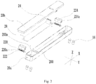
Fig. 3 is a sectional view of an upper housing, in an assembly state, of the driving power source as shown inFig. 2 ; -
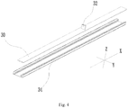
Fig. 4 is an exploded view of a light source module disclosed in the embodiment of the present application; -
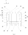
Fig. 5 is a side view of the track light disclosed in the embodiment of the present application; and -
Fig. 6 is a side view of the track light with a partial sectional structure disclosed in the embodiment of the present application. - 1-guide track, 10-track housing, 10a-accommodating cavity, 100-connection opening, 102-cavity bottom, 102a-second clamping slot, 104-cavity wall, 104a-first clamping slot, 104b-clamping bar, 12-insulating member, 120-cable slot, 120a-first guide surface, 14-conductive cable, 14a-first conductive cable, 14b-second conductive cable, 16-first magnetic member, 2-driving power source, 20-driving housing, 20a-upper housing, 20b-lower housing, 200-terminal guide slot, 200a-, 22-elastic conductive terminal, 22a-first elastic conductive terminal, 22b-second elastic conductive terminal, 220-conductive pin, 220a-abutting member, 220b-second guide surface, 222-elastic member, 224-conducting sheet, 224a-assembly gap, 24-output terminal, 26-second magnetic member, 28-driving board, 3-light source module, 30-light emitting component, 32-input terminal, and 34-lens.
- In order to make purpose, technical scheme and advantages of the present application clearer, the technical solutions of the present application will be described clearly and completely with reference to specific embodiments of the present application and corresponding drawings. Obviously, the described embodiments are only a part, not all, of the embodiments of the present application. Based on the embodiments in the present application, all other embodiments obtained by those skilled in the art without creative work belong to the protection scope of the present application.
- The technical solutions provided by each embodiment of the present application will be described in detail with reference to the attached drawings.
- An embodiment of the present application discloses a track light, as shown in
Fig. 1 to Fig. 6 , including atrack 1, adriving power source 2 and a light source module 3. Generally, the track light is of a strip-shaped structure. In order to facilitate describing the structure, the track light is defined by adopting a length direction X, a width direction Y and a thickness direction Z in the present embodiment. - The
guide track 1 is used as a basic structure of the track light and is configured for fixing thedriving power source 2 and the light source module 3; and meanwhile, theguide track 1 also provides power for thedriving power source 2. In particular, as shown inFig. 1 ,Fig. 5 andFig. 6 , theguide track 1 includes atrack housing 10, insulatingmembers 12 andconductive cables 14, which extend in the length direction X. - Herein, the
track housing 10 is generally an aluminum extruded housing which is good in appearance, high in structural strength, favorable in molding process and relatively good in overall performances. Anaccommodating cavity 10a is formed by being surrounded by thetrack housing 10; theaccommodating cavity 10a includes a connection opening 100 in the thickness direction Z and acavity bottom 102 opposite to the connection opening 100; theaccommodating cavity 10a further includes twocavity walls 104 adjacent to the connection opening 100 in the width direction Y and oppositely disposed. The insulatingmembers 12 are configured for fixing theconductive cables 14 and isolating electric energy to avoid short circuits. In particular, the insulatingmembers 12 are fixedly disposed in theaccommodating cavity 10a; in this case, the insulatingmembers 12 can be fixedly disposed on thecavity bottom 102; theinsulating members 12 can also be fixedly disposed on thecavity walls 104. The side, facing to the center of theaccommodating cavity 10a, of theinsulating members 12 are provided withcable slot 120, and theconductive cables 14 are fixedly disposed in thecable slot 120. Theconductive cable 14 itself is provided with exposed conductive surface extending in the length direction X, and electric energy can be transmitted at any point on the conductive surface. It should be noted that, in some embodiments, it is possible that thetrack housing 10 is made of an insulating material; in this case, it is possible that the insulatingmembers 12 are directly fixed on thetrack housing 10, without provision of theconductive cables 14. - In the present embodiment, the
driving power source 2 is configured for obtaining electric energy from the guide track and transmit electric energy to the light source module 3. In particular, as shown inFig. 2 ,Fig. 3 ,Fig. 5 andFig. 6 , thedriving power source 2 includes adriving housing 20, elasticconductive terminals 22 and anoutput terminal 24, and in addition, generally further includes adriving board 28.Terminal guide slots 200 can be provided inside thedriving housing 20, for guiding the elasticconductive terminals 22; the elasticconductive terminals 22 are disposed in theterminal guide slots 200 and can only be popped out of thedriving housing 20 along theterminal guide slots 200. According to different positions of theconductive cables 14, extension directions of theterminal guide slots 200 are different. For example, when theconductive cables 14 are disposed at one side of thecavity bottom 102 along the thickness direction Z, theterminal guide slots 200 are also disposed along the thickness direction Z; and when theconductive cables 14 are disposed at one side of thecavity wall 104 along the width direction Y, theterminal guide slots 200 are also disposed along the width direction Y. - The
driving board 28 is also mounted in thedriving housing 20 and is configured for switching and controlling the power source. In order to conveniently mount the elasticconductive terminals 22 and the drivingboard 28 into the drivinghousing 20, the drivinghousing 20 in the present embodiment can be divided into two parts, that is, anupper housing 20a and alower housing 20b; and the two parts are connected by a structure such as a screw and a buckle. - As shown in
Fig. 3 , the light source module 3 generally includes alight emitting component 30 and aninput terminal 32; and thelight emitting component 30 is electrically connected with theinput terminal 32. An electric connection process of the light source module 3 can be realized by connecting theinput terminal 32 of the light source module 3 to theoutput terminal 24 after the drivingpower source 2 is mounted. Theinput terminal 32 and theoutput terminal 24 can adopt a male and female terminal structure or a pin and elastic metal sheet matched structure and can further adopt various connection structures such as a golden finger connection structure, a pin connection structure and even a welded structure. - The present embodiment, the
cable slots 120 and the elasticconductive terminals 22 can be provided with guide surfaces for cooperation. When the drivingpower source 2 is placed into theaccommodating cavity 10a through theconnection opening 100, with the gradual deepening of the drivingpower source 2 into theaccommodating cavity 10a, the elasticconductive terminals 22 are capable of retracting towards the inside of the drivinghousing 20 under the guide of the guide surfaces; and the elasticconductive terminals 22, by virtue of its elasticity, can be re-popped out and extend into thecable slots 120 in the width direction Y after crossing the guide surfaces, to electrically connected with theconductive cables 14. The process of electric connection between the drivingpower source 2 and theguide track 1 is very simple, so that the assembly time is greatly shortened. - The
output terminal 24 is disposed at one side of the drivinghousing 20 in the thickness direction Z and is electrically connected with the elasticconductive terminals 22. For example, the elasticconductive terminals 22 and theoutput terminal 24 are electrically connected with the driving board 25 at the same time. - As shown in
Fig. 2 ,Fig. 3 andFig. 6 , the elasticconductive terminals 22 in the present embodiment can includeconductive pins 220,elastic members 222 andconductive sheets 224. Theconductive pins 220 are configured to extend out of the drivinghousing 10 and are electrically connected with theconductive cables 14. Theconductive pins 220 are provided with abuttingparts 220a. When the elastic conductive terminal 22 is disposed in theterminal guide slot 200, two ends of theelastic member 222 are respectively abutted with theabutting part 220a and theterminal guide slot 200 and apply an acting force for extending out of the drivinghousing 10 to theconductive pin 220. Theelastic members 222 can adopt various elastic structures such as spring and elastic sheet. Theconductive sheet 224 is disposed at a side of theabutting part 220a facing away from theelastic member 222, and is abutted with theabutting part 220a when theconductive pin 220 is electrically connected with theconductive cables 14. In this case, theoutput terminal 24 can be electrically connected with theconductive sheets 224 so as to achieve a stable electric connection structure. - The
conductive sheets 224 may be provided withassembly gaps 224a, and theconductive pins 220 extend into theassembly gaps 224a, in this way, theconductive sheets 224 can be at least abutted and matched with the abuttingparts 220a from two sides of theconductive pin 220; and therefore, the stability of electric connection can be improved. In order to fix theconductive sheets 224, theterminal guide slots 200 can be provided withclamping connection openings 200a; and theconductive sheet 224 is in clamping connection with and fixedly disposed in theclamping connection opening 200a. In addition, two ends of theconductive sheet 224 can also be bent or folded, so that theconductive sheet 224 become into a three-dimensional structure from a sheet to further improve the stability. - In the present embodiment, the guide surfaces can be disposed in the
cable slots 120 only; for example, edges of clamping hooks of thecable slots 120 are designed to be first guide surfaces 120a which are arc-shaped or obliquely extend. The guide surfaces can also be disposed on the elasticconductive terminals 22 only; for example, ends of theconductive pins 220 are designed to be second guide surfaces 220b which are arc-shaped. Of course, it is possible that thefirst guide surfaces 120a and the second guide surfaces 220b present at the same time, so that a more excellent guide effect is provided. Moreover, the specific shapes of the guide surfaces in the present embodiment are not particularly limited as long as a guide function is achieved. - A circuit is required to be formed for electric connection; and therefore, two electrodes with opposite electric properties are generally required to be connected at the same time. In the present embodiment, in order to improve the safety, a single one
conductive cable 14 can be only used as one electrode. Therefore, in order to form the circuit, theconductive cables 14 in the present embodiment include firstconductive cables 14a and secondconductive cables 14b which have opposite electric properties; the firstconductive cable 14a and the secondconductive cable 14b are required to be mutually staggered in the thickness direction Z; that is, they are different in distance from theconnection opening 100. The elasticconductive terminals 22 also include first elasticconductive terminals 22a and second elasticconductive terminals 22b; the first elastic conductive terminal 22a and the second elastic conductive terminal 22b can have the identical structure, but are also required to be mutually staggered in the thickness direction Z. When the drivingpower source 2 is mounted at a preset position, the first elasticconductive terminals 22a are electrically connected with the firstconductive cables 14a, and the second elasticconductive terminals 22b are electrically connected with the secondconductive cables 14b, so that a connection circuit is formed. - Furthermore, in order to improve the stability of electric connection, two first
conductive cables 14a and two secondconductive cables 14b can be disposed at the same time in the present embodiment, the two firstconductive cables 14a are oppositely disposed in the width direction Y, and the two secondconductive cables 14b are also oppositely disposed in the width direction Y. - Meanwhile, on the driving
power source 2, the number of the first elasticconductive terminals 22a and the number of the second elasticconductive terminals 22b are both two; the two first elasticconductive terminals 22a are disposed back to back in the width direction Y and are electrically connected with different firstconductive cables 14a respectively; the two second elasticconductive terminals 22b are also disposed back to back in the width direction Y and are electrically connected with different secondconductive cables 14b respectively. Structures for fixing the elasticconductive terminals 22 at two sides can be identical or different as long as there are no substantial influences to electric connection property. For example, the elasticconductive terminals 22 can be fixedly disposed by the insulatingmembers 12 respectively disposed at two sides. - In this way, the driving
power source 2 can be electrically connected with the two separately disposed elasticconductive terminals 22 at the same time when extending into theaccommodating cavity 10a, which is equivalent to that two circuits connected in parallel are formed; therefore, the safety can be increased exponentially. The insulatingmembers 12 can be fixed on thecavity walls 104 in a clamping connection way; for example, thewalls 104 are provided withfirst clamping slots 104a, and the insulatingmembers 12 are clamped inside thefirst clamping slots 104a. - In the present embodiment, in order to rapidly mount the driving
power source 2, thecavity bottom 102 of theguide track 1 can be provided with firstmagnetic members 16. Similar to the way of fixing the insulatingmembers 12, the firstmagnetic members 16 can be clamped and fixed on thecavity bottom 102 by thesecond clamping slots 102a provided on thecavity bottom 102. Meanwhile, secondmagnetic members 26 are provided inside the drivingpower source 2; the secondmagnetic members 26 can be fixed at the side of thepower source housing 20 facing away from theoutput terminal 24. - When the driving
power source 2 is placed into theguide track 1 through theconnection opening 100, the firstmagnetic members 16 and the secondmagnetic members 26 are capable of generating magnetic adsorption effects so as to be rapidly close to each other and finally fixedly connected together. During magnetic adsorption, electric connection between each of the elasticconductive terminals 22 and each of theconductive cables 14 can also be automatically completed. When the position of the drivingpower source 2 is required to be moved, it can be realized just by pulling the drivingpower source 2 against friction force. In the present embodiment, both the firstmagnetic members 16 and the secondmagnetic members 26 can be magnets; however, the cost is relatively high. Preferably, the firstmagnetic member 16 can adopt magnetic metal plate such as iron plate; and the magnetic metal plate can extend to any position of theguide track 1 in the length direction X; and the secondmagnetic members 26 adopt magnet such as magnetic stone; and the magnetic metal plate is adsorbed by the magnets. The magnetic metal plate is low in price; and therefore, the cost can be effectively reduced. The magnets can be fixed on the drivinghousing 20 by structure such as clamping hook. - The light source module 3 can adopt a spotlight, a downlight and the like or adopt a linear module; the light source module 3 of linear module generally further includes a
lens 34 configured for distributing light for thelight emitting component 30. In order to fix the lens, structures such as clampingbars 104b can be disposed on thecavity walls 104 to clamp and fix thelens 34; and thelens 34 can cover theconnection opening 100 after being fixed. In this case, thelight emitting component 30 can be fixedly connected with thelens 34, so that the structural stability of thelight emitting component 30 and thelens 34 is improved. - By using the track light provided by the embodiment of the present application, the assembly time can be saved.
- In the above embodiments of the present application, the differences among the respective embodiments are particularly described; different optimization features among the respective embodiments can be combined to form a better embodiment as long as they are not contradictory. Considering the brevity of description, they will not be repeated herein.
- The above described is only embodiments of the present application, and is not intended to limit the present application. For those skilled in the art, various modifications and variations are possible. Any modification, equivalent substitution, improvement, and the like made within the spirit and principle of the present application shall be included within the scope of the claims of the present application.
Claims (15)
- A track light, with a length direction, a width direction and a thickness direction, characterized in that, the track light comprises a guide track, a driving power source and a light source module;
the guide track comprises a track housing and a conductive cable extending along the length direction; the track housing comprises an accommodating cavity, the accommodating cavity comprises a connection opening located in the thickness direction, and the conductive cable is fixed in the accommodating cavity;
the driving power source comprises a driving housing, an elastic conductive terminal and an output terminal, the elastic conductive terminal is capable of being popped out of the driving housing, and the output terminal is disposed at a side of the driving housing and is electrically connected with the elastic conductive terminal;
the light source module comprises a light emitting component and an input terminal, the light emitting component is electrically connected with the input terminal, and the input terminal is connected with the output terminal;
when the driving power source and the light source module are into the accommodating cavity through the connection opening, the elastic conductive terminal is capable of being electrically connected with the conductive cable. - The track light according to claim 1, characterized in that, the accommodating cavity comprises a cavity bottom opposite to the connection opening in the thickness direction and two cavity walls close to the connection opening which are oppositely disposed along the width direction, the conductive cable is located at a side of the accommodating cavity in the width direction, and the elastic conductive terminal is only capable of being popped out of the driving housing along the width direction.
- The track light according to claim 2, characterized in that, the track light further comprises an insulating member fixed in the accommodating cavity, a side of the insulating member facing away from the cavity wall is provided with a cable slot, and the conductive cable is fixed in the cable slot.
- The track light according to claim 3, characterized in that, the cable slot and/or the elastic conductive terminal are provided with guide surface(s), when the driving power source is into the accommodating cavity through the connection opening, the elastic conductive terminal is capable of retracting towards an inside of the driving housing under the guide of the guide surface(s), and the elastic conductive terminal is capable of extending into the cable slot along the width direction after crossing the guide surface(s) and is electrically connected with the conductive cable.
- The track light according to claim 4, characterized in that, the conductive cable comprises a first conductive cable and a second conductive cable with opposite electric properties, the first conductive cable and the second conductive cable are mutually staggered in the thickness direction, the elastic conductive terminal comprises a first elastic conductive terminal and a second elastic conductive terminal, the first elastic conductive terminal and the second elastic conductive terminal are mutually staggered in the thickness direction, the first elastic conductive terminal is electrically connected with the first conductive cable, and the second elastic conductive terminal is electrically connected with the second conductive cable.
- The track light according to claim 5, characterized in that, two of the first conductive cables and two of the second conductive cables are provided, the two of the first conductive cables are oppositely disposed along the width direction, and the two of the second conductive cables are oppositely disposed along the width direction;
two of the first elastic conductive terminals and two of the second elastic conductive terminals are provided, the two of the first elastic conductive terminals are disposed back to back along the width direction and are electrically connected with the different first conductive cables respectively, and the two second elastic conductive terminals are disposed back to back along the width direction and are electrically connected with the different second conductive cables respectively. - The track light according to any one of claims 2 to 6, characterized in that, a terminal guide slot extending along the width direction is provided inside the driving housing, and the elastic conductive terminal is disposed in the terminal guide slot.
- The track light according to claim 7, characterized in that, the elastic conductive terminal comprises a conductive pin, an elastic member and a conductive sheet; the conductive pin is configured to extend out of the driving housing and electrically connect with the conductive cable, the conductive pin is further provided with an abutting part, two ends of the elastic member is abutted with the abutting part and the terminal guide slot respectively, and the elastic member applies an acting force to make the conductive pin extend out of the driving housing, the conductive sheet is disposed at a side of the abutting part facing away from the elastic member and abutted with the abutting part when the conductive pin is electrically connected with the conductive cable, and the output terminal is electrically connected with the conductive sheet.
- The track light according to claim 8, characterized in that, the conductive sheet is provided with an assembly gap, and the conductive pin extends in through the assembly gap.
- The track light according to claim 8, characterized in that, the terminal guide slot is provided with a clamping connection opening, and the conductive sheet is clamped into the clamping connection opening.
- The track light according to any one of claims 3 to 6, characterized in that, the cavity wall is provided with a first clamping slot, and the insulating member is in clamping connected in the first clamping slot.
- The track light according to any one of claims 2 to 6, characterized in that, the guide track comprises a first magnetic member fixed on the cavity bottom, the driving power source comprises a second magnetic member fixed at a side of the power source housing facing away from the output terminal, and the first magnetic member and the second magnetic member are capable of being fixedly connected by magnetic adsorption.
- The track light according to claim 12, characterized in that, the cavity bottom is provided with a second clamping slot, and the first magnetic member is fixed in the second clamping slot.
- The track light according to claim 12, characterized in that, the first magnetic member is a magnetic metal plate, and the second magnetic member is a magnet.
- The track light according to any one of claims 1 to 6, characterized in that, the light source module further comprises a lens covering the connection opening and in clamping connection with the accommodating cavity, and the light emitting component is fixedly connected with the lens.
Applications Claiming Priority (3)
| Application Number | Priority Date | Filing Date | Title |
|---|---|---|---|
| CN201810825743.0A CN108826114A (en) | 2018-07-25 | 2018-07-25 | track lamp |
| CN201821187374.9U CN208620128U (en) | 2018-07-25 | 2018-07-25 | Track lamp |
| PCT/CN2019/097133 WO2020020104A1 (en) | 2018-07-25 | 2019-07-22 | Rail light |
Publications (3)
| Publication Number | Publication Date |
|---|---|
| EP3798504A1 true EP3798504A1 (en) | 2021-03-31 |
| EP3798504A4 EP3798504A4 (en) | 2021-06-30 |
| EP3798504B1 EP3798504B1 (en) | 2023-05-10 |
Family
ID=69180307
Family Applications (1)
| Application Number | Title | Priority Date | Filing Date |
|---|---|---|---|
| EP19840257.0A Active EP3798504B1 (en) | 2018-07-25 | 2019-07-22 | Rail light |
Country Status (3)
| Country | Link |
|---|---|
| US (1) | US11236898B2 (en) |
| EP (1) | EP3798504B1 (en) |
| WO (1) | WO2020020104A1 (en) |
Families Citing this family (8)
| Publication number | Priority date | Publication date | Assignee | Title |
|---|---|---|---|---|
| CN111412441A (en) * | 2020-03-25 | 2020-07-14 | 广东科谷电源股份有限公司 | Track lamp power pack structure |
| USD955035S1 (en) * | 2020-05-27 | 2022-06-14 | Lumenture, Inc. | Lighting track |
| US11199300B1 (en) * | 2020-06-11 | 2021-12-14 | Elemental LED, Inc. | Channels and lenses for linear lighting |
| CN113154291B (en) * | 2021-04-25 | 2025-05-23 | 欧普照明股份有限公司 | A magnetic conductive track and lighting equipment |
| CN114857553B (en) * | 2022-05-31 | 2024-02-13 | 公牛集团股份有限公司 | Lamp and assembly method |
| CN115064911B (en) * | 2022-06-30 | 2025-10-28 | 欧普照明股份有限公司 | Tracks, adapters and electrical systems |
| CN115218164B (en) * | 2022-07-25 | 2026-01-30 | 惠州市西顿光电有限公司 | Power drive structure, track linear lighting system and lighting fixtures |
| CN116180964B (en) * | 2023-04-28 | 2023-06-23 | 中国建筑第五工程局有限公司 | A large-space multifunctional ceiling assembly |
Family Cites Families (28)
| Publication number | Priority date | Publication date | Assignee | Title |
|---|---|---|---|---|
| FR2809159A1 (en) * | 2000-03-06 | 2001-11-23 | Alain Minville | Lighting cable conduit system in which wiring is run to connect with lamps illuminating wall mounted pictures or other objects |
| US7632004B2 (en) * | 2004-07-06 | 2009-12-15 | Tseng-Lu Chien | LED night light with more than 1 optics means |
| US7306359B2 (en) * | 2004-05-11 | 2007-12-11 | Harwood Ronald P | Recessed adjustable low voltage track lighting |
| DE202004020011U1 (en) * | 2004-12-27 | 2005-03-17 | Hidde Gregor | Configurable current and light rail system for current supply and data transfer for electric loads such as lighting systems |
| US8061865B2 (en) * | 2005-05-23 | 2011-11-22 | Philips Solid-State Lighting Solutions, Inc. | Methods and apparatus for providing lighting via a grid system of a suspended ceiling |
| US7762821B2 (en) * | 2006-10-17 | 2010-07-27 | Worthington Armstrong Venture | Electrified ceiling framework |
| US8915609B1 (en) * | 2008-03-20 | 2014-12-23 | Cooper Technologies Company | Systems, methods, and devices for providing a track light and portable light |
| US8348492B2 (en) * | 2008-05-06 | 2013-01-08 | Koninklijke Philips Electronics N.V. | Movable LED track luminaire |
| CN201599752U (en) * | 2009-12-21 | 2010-10-06 | 东莞华明灯具有限公司 | Magnetic track lamp |
| TWM389208U (en) * | 2010-04-01 | 2010-09-21 | Lebensstil Technology Co Ltd | Assembled structure of illumination lamp |
| CN201925881U (en) * | 2010-12-08 | 2011-08-10 | 林万炯 | Slide rail lamp with lamp holders capable of being increased or decreased at random |
| CN201983038U (en) * | 2011-01-24 | 2011-09-21 | 林万炯 | Slide rail lamp |
| US9673582B2 (en) * | 2012-01-17 | 2017-06-06 | Joseph Guilmette | Modular housing and track assemblies for tubular lamps |
| US9097411B2 (en) * | 2012-01-17 | 2015-08-04 | Joseph Guilmette | Multiple-mode integrated track fixture for high efficiency tubular lamps |
| DE202014100627U1 (en) * | 2013-02-13 | 2014-05-12 | Elive Llc | LED lighting rail |
| KR101351358B1 (en) * | 2013-03-05 | 2014-01-23 | 주식회사 린노 | Line-type lighting apparatus |
| CN104235686B (en) * | 2014-08-19 | 2017-01-18 | 苏州市琳珂照明科技有限公司 | LED (light-emitting diode) lamp |
| CN204187403U (en) * | 2014-10-08 | 2015-03-04 | 中山市尚有科技照明有限公司 | A magnetic track light |
| WO2016127288A1 (en) * | 2015-02-09 | 2016-08-18 | 鲁周波 | Guide rail type led lamp |
| CN204513291U (en) * | 2015-04-15 | 2015-07-29 | 伍必胜 | Magnetic mounting structure for track lamps |
| US9759403B2 (en) * | 2015-09-21 | 2017-09-12 | Generation Brands Llc | Recessed lighting system for direct and indirect lighting |
| KR101710281B1 (en) * | 2015-10-22 | 2017-03-06 | 주식회사 린노 | Linear lighting device capable of wire-communication |
| US20170184290A1 (en) * | 2015-12-29 | 2017-06-29 | Davinci Opto Corp. | Track system |
| US9923341B1 (en) * | 2016-05-16 | 2018-03-20 | Instorescreen, Llc | Track power supply system |
| CN107388108A (en) * | 2017-08-29 | 2017-11-24 | 中山市乐派光电科技有限公司 | A kind of four trajectory lamps |
| US20190249854A1 (en) * | 2018-02-11 | 2019-08-15 | Giotto's Ind.Inc. | Rail Structure And Rail Lighting Structure |
| CN108826114A (en) * | 2018-07-25 | 2018-11-16 | 苏州欧普照明有限公司 | track lamp |
| CN208620128U (en) * | 2018-07-25 | 2019-03-19 | 苏州欧普照明有限公司 | Track lamp |
-
2019
- 2019-07-22 EP EP19840257.0A patent/EP3798504B1/en active Active
- 2019-07-22 WO PCT/CN2019/097133 patent/WO2020020104A1/en not_active Ceased
-
2020
- 2020-12-30 US US17/138,883 patent/US11236898B2/en active Active
Also Published As
| Publication number | Publication date |
|---|---|
| US20210116120A1 (en) | 2021-04-22 |
| US11236898B2 (en) | 2022-02-01 |
| EP3798504A4 (en) | 2021-06-30 |
| WO2020020104A1 (en) | 2020-01-30 |
| EP3798504B1 (en) | 2023-05-10 |
Similar Documents
| Publication | Publication Date | Title |
|---|---|---|
| US11236898B2 (en) | Track light | |
| US10976012B2 (en) | Light source apparatus and lighting device | |
| CN108826114A (en) | track lamp | |
| US9318831B2 (en) | Connector | |
| CN113154291B (en) | A magnetic conductive track and lighting equipment | |
| EP4310390A1 (en) | Magnetic conductive track and lighting device | |
| CN113708133B (en) | Removable function modules and sockets | |
| CN208620128U (en) | Track lamp | |
| US10520180B1 (en) | Lamp | |
| EP3979274A1 (en) | Inductive framework, inductive device, and lamp | |
| CN217882024U (en) | Electrical connection device and track lamp assembly | |
| CN115064890A (en) | Electrical connection device and track lamp assembly | |
| WO2025201402A1 (en) | Electronic module of modular industrial control device | |
| EP3974703A1 (en) | Magnetic attraction conductive track, adapter, electrical device and electrical system | |
| CN209930489U (en) | Earphone with detachable microphone | |
| CN102592888A (en) | Connecting device adaptable to different contactors | |
| CN214840317U (en) | A magnetically attracted conductive track and lighting equipment | |
| CN219655963U (en) | Spliced office lamp | |
| FI832953A0 (en) | STOPPING REQUIREMENTS FOR ELECTRIC SHOCKING | |
| CN219140694U (en) | Guide rail and guide rail assembly using same | |
| CN222051660U (en) | A circuit breaker mounting assembly | |
| CN218033054U (en) | Relay connector and relay connection structure of LED wire slot lamp | |
| GB2456132A (en) | A low-profile planar transformer with a particular insulation arrangement | |
| CN207455508U (en) | A kind of modular lighting lamps and lanterns and its connector | |
| CN219535004U (en) | Novel connecting piece and office lamp |
Legal Events
| Date | Code | Title | Description |
|---|---|---|---|
| STAA | Information on the status of an ep patent application or granted ep patent |
Free format text: STATUS: THE INTERNATIONAL PUBLICATION HAS BEEN MADE |
|
| PUAI | Public reference made under article 153(3) epc to a published international application that has entered the european phase |
Free format text: ORIGINAL CODE: 0009012 |
|
| STAA | Information on the status of an ep patent application or granted ep patent |
Free format text: STATUS: REQUEST FOR EXAMINATION WAS MADE |
|
| 17P | Request for examination filed |
Effective date: 20201223 |
|
| AK | Designated contracting states |
Kind code of ref document: A1 Designated state(s): AL AT BE BG CH CY CZ DE DK EE ES FI FR GB GR HR HU IE IS IT LI LT LU LV MC MK MT NL NO PL PT RO RS SE SI SK SM TR |
|
| AX | Request for extension of the european patent |
Extension state: BA ME |
|
| A4 | Supplementary search report drawn up and despatched |
Effective date: 20210528 |
|
| RIC1 | Information provided on ipc code assigned before grant |
Ipc: F21S 8/00 20060101AFI20210521BHEP Ipc: F21V 21/35 20060101ALI20210521BHEP Ipc: F21V 23/00 20150101ALI20210521BHEP Ipc: F21V 23/06 20060101ALI20210521BHEP Ipc: F21V 5/04 20060101ALI20210521BHEP Ipc: F21V 19/00 20060101ALI20210521BHEP Ipc: F21V 17/10 20060101ALN20210521BHEP |
|
| DAV | Request for validation of the european patent (deleted) | ||
| DAX | Request for extension of the european patent (deleted) | ||
| RIC1 | Information provided on ipc code assigned before grant |
Ipc: F21V 17/10 20060101ALN20220927BHEP Ipc: F21V 19/00 20060101ALI20220927BHEP Ipc: F21V 5/04 20060101ALI20220927BHEP Ipc: F21V 23/06 20060101ALI20220927BHEP Ipc: F21V 23/00 20150101ALI20220927BHEP Ipc: F21V 21/35 20060101ALI20220927BHEP Ipc: F21S 8/00 20060101AFI20220927BHEP |
|
| RIC1 | Information provided on ipc code assigned before grant |
Ipc: F21V 17/10 20060101ALN20221003BHEP Ipc: F21V 19/00 20060101ALI20221003BHEP Ipc: F21V 5/04 20060101ALI20221003BHEP Ipc: F21V 23/06 20060101ALI20221003BHEP Ipc: F21V 23/00 20150101ALI20221003BHEP Ipc: F21V 21/35 20060101ALI20221003BHEP Ipc: F21S 8/00 20060101AFI20221003BHEP |
|
| GRAP | Despatch of communication of intention to grant a patent |
Free format text: ORIGINAL CODE: EPIDOSNIGR1 |
|
| STAA | Information on the status of an ep patent application or granted ep patent |
Free format text: STATUS: GRANT OF PATENT IS INTENDED |
|
| RIC1 | Information provided on ipc code assigned before grant |
Ipc: F21V 17/10 20060101ALN20221020BHEP Ipc: F21V 19/00 20060101ALI20221020BHEP Ipc: F21V 5/04 20060101ALI20221020BHEP Ipc: F21V 23/06 20060101ALI20221020BHEP Ipc: F21V 23/00 20150101ALI20221020BHEP Ipc: F21V 21/35 20060101ALI20221020BHEP Ipc: F21S 8/00 20060101AFI20221020BHEP |
|
| INTG | Intention to grant announced |
Effective date: 20221121 |
|
| GRAS | Grant fee paid |
Free format text: ORIGINAL CODE: EPIDOSNIGR3 |
|
| GRAA | (expected) grant |
Free format text: ORIGINAL CODE: 0009210 |
|
| STAA | Information on the status of an ep patent application or granted ep patent |
Free format text: STATUS: THE PATENT HAS BEEN GRANTED |
|
| AK | Designated contracting states |
Kind code of ref document: B1 Designated state(s): AL AT BE BG CH CY CZ DE DK EE ES FI FR GB GR HR HU IE IS IT LI LT LU LV MC MK MT NL NO PL PT RO RS SE SI SK SM TR |
|
| REG | Reference to a national code |
Ref country code: GB Ref legal event code: FG4D |
|
| REG | Reference to a national code |
Ref country code: AT Ref legal event code: REF Ref document number: 1566975 Country of ref document: AT Kind code of ref document: T Effective date: 20230515 Ref country code: CH Ref legal event code: EP |
|
| REG | Reference to a national code |
Ref country code: DE Ref legal event code: R096 Ref document number: 602019028887 Country of ref document: DE |
|
| REG | Reference to a national code |
Ref country code: IE Ref legal event code: FG4D |
|
| REG | Reference to a national code |
Ref country code: NL Ref legal event code: FP |
|
| REG | Reference to a national code |
Ref country code: LT Ref legal event code: MG9D |
|
| REG | Reference to a national code |
Ref country code: AT Ref legal event code: MK05 Ref document number: 1566975 Country of ref document: AT Kind code of ref document: T Effective date: 20230510 |
|
| PG25 | Lapsed in a contracting state [announced via postgrant information from national office to epo] |
Ref country code: SE Free format text: LAPSE BECAUSE OF FAILURE TO SUBMIT A TRANSLATION OF THE DESCRIPTION OR TO PAY THE FEE WITHIN THE PRESCRIBED TIME-LIMIT Effective date: 20230510 Ref country code: PT Free format text: LAPSE BECAUSE OF FAILURE TO SUBMIT A TRANSLATION OF THE DESCRIPTION OR TO PAY THE FEE WITHIN THE PRESCRIBED TIME-LIMIT Effective date: 20230911 Ref country code: NO Free format text: LAPSE BECAUSE OF FAILURE TO SUBMIT A TRANSLATION OF THE DESCRIPTION OR TO PAY THE FEE WITHIN THE PRESCRIBED TIME-LIMIT Effective date: 20230810 Ref country code: ES Free format text: LAPSE BECAUSE OF FAILURE TO SUBMIT A TRANSLATION OF THE DESCRIPTION OR TO PAY THE FEE WITHIN THE PRESCRIBED TIME-LIMIT Effective date: 20230510 Ref country code: AT Free format text: LAPSE BECAUSE OF FAILURE TO SUBMIT A TRANSLATION OF THE DESCRIPTION OR TO PAY THE FEE WITHIN THE PRESCRIBED TIME-LIMIT Effective date: 20230510 |
|
| PG25 | Lapsed in a contracting state [announced via postgrant information from national office to epo] |
Ref country code: RS Free format text: LAPSE BECAUSE OF FAILURE TO SUBMIT A TRANSLATION OF THE DESCRIPTION OR TO PAY THE FEE WITHIN THE PRESCRIBED TIME-LIMIT Effective date: 20230510 Ref country code: PL Free format text: LAPSE BECAUSE OF FAILURE TO SUBMIT A TRANSLATION OF THE DESCRIPTION OR TO PAY THE FEE WITHIN THE PRESCRIBED TIME-LIMIT Effective date: 20230510 Ref country code: LV Free format text: LAPSE BECAUSE OF FAILURE TO SUBMIT A TRANSLATION OF THE DESCRIPTION OR TO PAY THE FEE WITHIN THE PRESCRIBED TIME-LIMIT Effective date: 20230510 Ref country code: LT Free format text: LAPSE BECAUSE OF FAILURE TO SUBMIT A TRANSLATION OF THE DESCRIPTION OR TO PAY THE FEE WITHIN THE PRESCRIBED TIME-LIMIT Effective date: 20230510 Ref country code: IS Free format text: LAPSE BECAUSE OF FAILURE TO SUBMIT A TRANSLATION OF THE DESCRIPTION OR TO PAY THE FEE WITHIN THE PRESCRIBED TIME-LIMIT Effective date: 20230910 Ref country code: HR Free format text: LAPSE BECAUSE OF FAILURE TO SUBMIT A TRANSLATION OF THE DESCRIPTION OR TO PAY THE FEE WITHIN THE PRESCRIBED TIME-LIMIT Effective date: 20230510 Ref country code: GR Free format text: LAPSE BECAUSE OF FAILURE TO SUBMIT A TRANSLATION OF THE DESCRIPTION OR TO PAY THE FEE WITHIN THE PRESCRIBED TIME-LIMIT Effective date: 20230811 |
|
| PG25 | Lapsed in a contracting state [announced via postgrant information from national office to epo] |
Ref country code: FI Free format text: LAPSE BECAUSE OF FAILURE TO SUBMIT A TRANSLATION OF THE DESCRIPTION OR TO PAY THE FEE WITHIN THE PRESCRIBED TIME-LIMIT Effective date: 20230510 |
|
| PG25 | Lapsed in a contracting state [announced via postgrant information from national office to epo] |
Ref country code: SK Free format text: LAPSE BECAUSE OF FAILURE TO SUBMIT A TRANSLATION OF THE DESCRIPTION OR TO PAY THE FEE WITHIN THE PRESCRIBED TIME-LIMIT Effective date: 20230510 |
|
| PG25 | Lapsed in a contracting state [announced via postgrant information from national office to epo] |
Ref country code: SM Free format text: LAPSE BECAUSE OF FAILURE TO SUBMIT A TRANSLATION OF THE DESCRIPTION OR TO PAY THE FEE WITHIN THE PRESCRIBED TIME-LIMIT Effective date: 20230510 Ref country code: SK Free format text: LAPSE BECAUSE OF FAILURE TO SUBMIT A TRANSLATION OF THE DESCRIPTION OR TO PAY THE FEE WITHIN THE PRESCRIBED TIME-LIMIT Effective date: 20230510 Ref country code: RO Free format text: LAPSE BECAUSE OF FAILURE TO SUBMIT A TRANSLATION OF THE DESCRIPTION OR TO PAY THE FEE WITHIN THE PRESCRIBED TIME-LIMIT Effective date: 20230510 Ref country code: EE Free format text: LAPSE BECAUSE OF FAILURE TO SUBMIT A TRANSLATION OF THE DESCRIPTION OR TO PAY THE FEE WITHIN THE PRESCRIBED TIME-LIMIT Effective date: 20230510 Ref country code: DK Free format text: LAPSE BECAUSE OF FAILURE TO SUBMIT A TRANSLATION OF THE DESCRIPTION OR TO PAY THE FEE WITHIN THE PRESCRIBED TIME-LIMIT Effective date: 20230510 Ref country code: CZ Free format text: LAPSE BECAUSE OF FAILURE TO SUBMIT A TRANSLATION OF THE DESCRIPTION OR TO PAY THE FEE WITHIN THE PRESCRIBED TIME-LIMIT Effective date: 20230510 |
|
| REG | Reference to a national code |
Ref country code: DE Ref legal event code: R097 Ref document number: 602019028887 Country of ref document: DE |
|
| PG25 | Lapsed in a contracting state [announced via postgrant information from national office to epo] |
Ref country code: MC Free format text: LAPSE BECAUSE OF FAILURE TO SUBMIT A TRANSLATION OF THE DESCRIPTION OR TO PAY THE FEE WITHIN THE PRESCRIBED TIME-LIMIT Effective date: 20230510 |
|
| PG25 | Lapsed in a contracting state [announced via postgrant information from national office to epo] |
Ref country code: MC Free format text: LAPSE BECAUSE OF FAILURE TO SUBMIT A TRANSLATION OF THE DESCRIPTION OR TO PAY THE FEE WITHIN THE PRESCRIBED TIME-LIMIT Effective date: 20230510 |
|
| REG | Reference to a national code |
Ref country code: CH Ref legal event code: PL |
|
| PLBE | No opposition filed within time limit |
Free format text: ORIGINAL CODE: 0009261 |
|
| STAA | Information on the status of an ep patent application or granted ep patent |
Free format text: STATUS: NO OPPOSITION FILED WITHIN TIME LIMIT |
|
| PG25 | Lapsed in a contracting state [announced via postgrant information from national office to epo] |
Ref country code: LU Free format text: LAPSE BECAUSE OF NON-PAYMENT OF DUE FEES Effective date: 20230722 |
|
| PG25 | Lapsed in a contracting state [announced via postgrant information from national office to epo] |
Ref country code: LU Free format text: LAPSE BECAUSE OF NON-PAYMENT OF DUE FEES Effective date: 20230722 |
|
| 26N | No opposition filed |
Effective date: 20240213 |
|
| REG | Reference to a national code |
Ref country code: IE Ref legal event code: MM4A |
|
| PG25 | Lapsed in a contracting state [announced via postgrant information from national office to epo] |
Ref country code: CH Free format text: LAPSE BECAUSE OF NON-PAYMENT OF DUE FEES Effective date: 20230731 |
|
| PG25 | Lapsed in a contracting state [announced via postgrant information from national office to epo] |
Ref country code: SI Free format text: LAPSE BECAUSE OF FAILURE TO SUBMIT A TRANSLATION OF THE DESCRIPTION OR TO PAY THE FEE WITHIN THE PRESCRIBED TIME-LIMIT Effective date: 20230510 |
|
| PG25 | Lapsed in a contracting state [announced via postgrant information from national office to epo] |
Ref country code: SI Free format text: LAPSE BECAUSE OF FAILURE TO SUBMIT A TRANSLATION OF THE DESCRIPTION OR TO PAY THE FEE WITHIN THE PRESCRIBED TIME-LIMIT Effective date: 20230510 Ref country code: IT Free format text: LAPSE BECAUSE OF FAILURE TO SUBMIT A TRANSLATION OF THE DESCRIPTION OR TO PAY THE FEE WITHIN THE PRESCRIBED TIME-LIMIT Effective date: 20230510 |
|
| PG25 | Lapsed in a contracting state [announced via postgrant information from national office to epo] |
Ref country code: IE Free format text: LAPSE BECAUSE OF NON-PAYMENT OF DUE FEES Effective date: 20230722 |
|
| PG25 | Lapsed in a contracting state [announced via postgrant information from national office to epo] |
Ref country code: IE Free format text: LAPSE BECAUSE OF NON-PAYMENT OF DUE FEES Effective date: 20230722 |
|
| PGFP | Annual fee paid to national office [announced via postgrant information from national office to epo] |
Ref country code: FR Payment date: 20240619 Year of fee payment: 6 |
|
| PGFP | Annual fee paid to national office [announced via postgrant information from national office to epo] |
Ref country code: BE Payment date: 20240726 Year of fee payment: 6 |
|
| PG25 | Lapsed in a contracting state [announced via postgrant information from national office to epo] |
Ref country code: BG Free format text: LAPSE BECAUSE OF FAILURE TO SUBMIT A TRANSLATION OF THE DESCRIPTION OR TO PAY THE FEE WITHIN THE PRESCRIBED TIME-LIMIT Effective date: 20230510 |
|
| PG25 | Lapsed in a contracting state [announced via postgrant information from national office to epo] |
Ref country code: BG Free format text: LAPSE BECAUSE OF FAILURE TO SUBMIT A TRANSLATION OF THE DESCRIPTION OR TO PAY THE FEE WITHIN THE PRESCRIBED TIME-LIMIT Effective date: 20230510 |
|
| PGFP | Annual fee paid to national office [announced via postgrant information from national office to epo] |
Ref country code: NL Payment date: 20250630 Year of fee payment: 7 |
|
| PG25 | Lapsed in a contracting state [announced via postgrant information from national office to epo] |
Ref country code: CY Free format text: LAPSE BECAUSE OF FAILURE TO SUBMIT A TRANSLATION OF THE DESCRIPTION OR TO PAY THE FEE WITHIN THE PRESCRIBED TIME-LIMIT; INVALID AB INITIO Effective date: 20190722 |
|
| PG25 | Lapsed in a contracting state [announced via postgrant information from national office to epo] |
Ref country code: HU Free format text: LAPSE BECAUSE OF FAILURE TO SUBMIT A TRANSLATION OF THE DESCRIPTION OR TO PAY THE FEE WITHIN THE PRESCRIBED TIME-LIMIT; INVALID AB INITIO Effective date: 20190722 |
|
| PGFP | Annual fee paid to national office [announced via postgrant information from national office to epo] |
Ref country code: DE Payment date: 20250711 Year of fee payment: 7 |
|
| PGFP | Annual fee paid to national office [announced via postgrant information from national office to epo] |
Ref country code: GB Payment date: 20250723 Year of fee payment: 7 |
|
| PG25 | Lapsed in a contracting state [announced via postgrant information from national office to epo] |
Ref country code: TR Free format text: LAPSE BECAUSE OF FAILURE TO SUBMIT A TRANSLATION OF THE DESCRIPTION OR TO PAY THE FEE WITHIN THE PRESCRIBED TIME-LIMIT Effective date: 20230510 |
|
| REG | Reference to a national code |
Ref country code: BE Ref legal event code: MM Effective date: 20250731 |
|
| PG25 | Lapsed in a contracting state [announced via postgrant information from national office to epo] |
Ref country code: BE Free format text: LAPSE BECAUSE OF NON-PAYMENT OF DUE FEES Effective date: 20250731 |
|
| PG25 | Lapsed in a contracting state [announced via postgrant information from national office to epo] |
Ref country code: FR Free format text: LAPSE BECAUSE OF NON-PAYMENT OF DUE FEES Effective date: 20250731 |