EP3798488A1 - Fitting nut, fitting, fluid pressure device, and fluid control system, and nut turning tool and fitting nut turning method - Google Patents
Fitting nut, fitting, fluid pressure device, and fluid control system, and nut turning tool and fitting nut turning method Download PDFInfo
- Publication number
- EP3798488A1 EP3798488A1 EP20198267.5A EP20198267A EP3798488A1 EP 3798488 A1 EP3798488 A1 EP 3798488A1 EP 20198267 A EP20198267 A EP 20198267A EP 3798488 A1 EP3798488 A1 EP 3798488A1
- Authority
- EP
- European Patent Office
- Prior art keywords
- tube portion
- nut
- diameter tube
- diameter
- fitting
- Prior art date
- Legal status (The legal status is an assumption and is not a legal conclusion. Google has not performed a legal analysis and makes no representation as to the accuracy of the status listed.)
- Granted
Links
Images









Classifications
-
- F—MECHANICAL ENGINEERING; LIGHTING; HEATING; WEAPONS; BLASTING
- F16—ENGINEERING ELEMENTS AND UNITS; GENERAL MEASURES FOR PRODUCING AND MAINTAINING EFFECTIVE FUNCTIONING OF MACHINES OR INSTALLATIONS; THERMAL INSULATION IN GENERAL
- F16L—PIPES; JOINTS OR FITTINGS FOR PIPES; SUPPORTS FOR PIPES, CABLES OR PROTECTIVE TUBING; MEANS FOR THERMAL INSULATION IN GENERAL
- F16L33/00—Arrangements for connecting hoses to rigid members; Rigid hose-connectors, i.e. single members engaging both hoses
- F16L33/24—Arrangements for connecting hoses to rigid members; Rigid hose-connectors, i.e. single members engaging both hoses with parts screwed directly on or into the hose
-
- F—MECHANICAL ENGINEERING; LIGHTING; HEATING; WEAPONS; BLASTING
- F16—ENGINEERING ELEMENTS AND UNITS; GENERAL MEASURES FOR PRODUCING AND MAINTAINING EFFECTIVE FUNCTIONING OF MACHINES OR INSTALLATIONS; THERMAL INSULATION IN GENERAL
- F16L—PIPES; JOINTS OR FITTINGS FOR PIPES; SUPPORTS FOR PIPES, CABLES OR PROTECTIVE TUBING; MEANS FOR THERMAL INSULATION IN GENERAL
- F16L33/00—Arrangements for connecting hoses to rigid members; Rigid hose-connectors, i.e. single members engaging both hoses
- F16L33/22—Arrangements for connecting hoses to rigid members; Rigid hose-connectors, i.e. single members engaging both hoses with means not mentioned in the preceding groups for gripping the hose between inner and outer parts
- F16L33/223—Arrangements for connecting hoses to rigid members; Rigid hose-connectors, i.e. single members engaging both hoses with means not mentioned in the preceding groups for gripping the hose between inner and outer parts the sealing surfaces being pressed together by means of a member, e.g. a swivel nut, screwed on or into one of the joint parts
-
- F—MECHANICAL ENGINEERING; LIGHTING; HEATING; WEAPONS; BLASTING
- F16—ENGINEERING ELEMENTS AND UNITS; GENERAL MEASURES FOR PRODUCING AND MAINTAINING EFFECTIVE FUNCTIONING OF MACHINES OR INSTALLATIONS; THERMAL INSULATION IN GENERAL
- F16L—PIPES; JOINTS OR FITTINGS FOR PIPES; SUPPORTS FOR PIPES, CABLES OR PROTECTIVE TUBING; MEANS FOR THERMAL INSULATION IN GENERAL
- F16L19/00—Joints in which sealing surfaces are pressed together by means of a member, e.g. a swivel nut, screwed on, or into, one of the joint parts
- F16L19/02—Pipe ends provided with collars or flanges, integral with the pipe or not, pressed together by a screwed member
-
- B—PERFORMING OPERATIONS; TRANSPORTING
- B25—HAND TOOLS; PORTABLE POWER-DRIVEN TOOLS; MANIPULATORS
- B25B—TOOLS OR BENCH DEVICES NOT OTHERWISE PROVIDED FOR, FOR FASTENING, CONNECTING, DISENGAGING, OR HOLDING
- B25B13/00—Spanners; Wrenches
- B25B13/02—Spanners; Wrenches with rigid jaws
- B25B13/08—Spanners; Wrenches with rigid jaws of open jaw type
-
- B—PERFORMING OPERATIONS; TRANSPORTING
- B25—HAND TOOLS; PORTABLE POWER-DRIVEN TOOLS; MANIPULATORS
- B25B—TOOLS OR BENCH DEVICES NOT OTHERWISE PROVIDED FOR, FOR FASTENING, CONNECTING, DISENGAGING, OR HOLDING
- B25B13/00—Spanners; Wrenches
- B25B13/48—Spanners; Wrenches for special purposes
- B25B13/50—Spanners; Wrenches for special purposes for operating on work of special profile, e.g. pipes
- B25B13/5008—Spanners; Wrenches for special purposes for operating on work of special profile, e.g. pipes for operating on pipes or cylindrical objects
- B25B13/5016—Spanners; Wrenches for special purposes for operating on work of special profile, e.g. pipes for operating on pipes or cylindrical objects by externally gripping the pipe
- B25B13/5025—Spanners; Wrenches for special purposes for operating on work of special profile, e.g. pipes for operating on pipes or cylindrical objects by externally gripping the pipe using a pipe wrench type tool
- B25B13/5033—Spanners; Wrenches for special purposes for operating on work of special profile, e.g. pipes for operating on pipes or cylindrical objects by externally gripping the pipe using a pipe wrench type tool with fixed jaws
-
- F—MECHANICAL ENGINEERING; LIGHTING; HEATING; WEAPONS; BLASTING
- F16—ENGINEERING ELEMENTS AND UNITS; GENERAL MEASURES FOR PRODUCING AND MAINTAINING EFFECTIVE FUNCTIONING OF MACHINES OR INSTALLATIONS; THERMAL INSULATION IN GENERAL
- F16L—PIPES; JOINTS OR FITTINGS FOR PIPES; SUPPORTS FOR PIPES, CABLES OR PROTECTIVE TUBING; MEANS FOR THERMAL INSULATION IN GENERAL
- F16L47/00—Connecting arrangements or other fittings specially adapted to be made of plastics or to be used with pipes made of plastics
- F16L47/04—Connecting arrangements or other fittings specially adapted to be made of plastics or to be used with pipes made of plastics with a swivel nut or collar engaging the pipe
- F16L47/041—Connecting arrangements or other fittings specially adapted to be made of plastics or to be used with pipes made of plastics with a swivel nut or collar engaging the pipe the plastic pipe end being flared either before or during the making of the connection
-
- F—MECHANICAL ENGINEERING; LIGHTING; HEATING; WEAPONS; BLASTING
- F16—ENGINEERING ELEMENTS AND UNITS; GENERAL MEASURES FOR PRODUCING AND MAINTAINING EFFECTIVE FUNCTIONING OF MACHINES OR INSTALLATIONS; THERMAL INSULATION IN GENERAL
- F16L—PIPES; JOINTS OR FITTINGS FOR PIPES; SUPPORTS FOR PIPES, CABLES OR PROTECTIVE TUBING; MEANS FOR THERMAL INSULATION IN GENERAL
- F16L55/00—Devices or appurtenances for use in, or in connection with, pipes or pipe systems
-
- F—MECHANICAL ENGINEERING; LIGHTING; HEATING; WEAPONS; BLASTING
- F16—ENGINEERING ELEMENTS AND UNITS; GENERAL MEASURES FOR PRODUCING AND MAINTAINING EFFECTIVE FUNCTIONING OF MACHINES OR INSTALLATIONS; THERMAL INSULATION IN GENERAL
- F16B—DEVICES FOR FASTENING OR SECURING CONSTRUCTIONAL ELEMENTS OR MACHINE PARTS TOGETHER, e.g. NAILS, BOLTS, CIRCLIPS, CLAMPS, CLIPS OR WEDGES; JOINTS OR JOINTING
- F16B23/00—Specially shaped nuts or heads of bolts or screws for rotations by a tool
- F16B23/0061—Specially shaped nuts or heads of bolts or screws for rotations by a tool with grooves, notches or splines on the external peripheral surface designed for tools engaging in radial direction
Definitions
- the present invention relates to a fitting nut for connecting a joint body and a pipe member for sending a fluid, a fitting including the joint body and the fitting nut, a fluid pressure device including the fitting, and a fluid control system including a plurality of the fluid pressure devices, and to a nut turning tool suitable to turn the fitting nut, and a method for turning the fitting nut.
- Apparatuses for manufacturing semiconductors, medical products, etc. or for processing foods etc. for example, are supplied with high-purity medical fluids, ultrapure water, etc. from supply sources.
- a flow rate control valve which is one type of a fluid pressure device, is interposed in the piping.
- a fluid supply pipe is interposed between the supply source and the flow rate control valve, while a fluid discharge pipe is interposed between the flow rate control valve and the manufacturing or processing apparatus etc.
- the fluid supply pipe or fluid discharge pipe and the flow rate control valve are connected together through a fitting.
- the fitting is formed by engaging a female thread formed on the inner periphery of a first joint member with a male thread formed on the outer periphery of a second joint member.
- the male screw is screwed into the female screw by turning the first joint member or the second joint member by means of a suitable tool, like a spanner, wrench, or the like.
- a plurality of flow rate control valves may be arranged in a concentrated manner in order to make the manufacturing apparatus etc. compact.
- the fittings of the individual flow rate control valves are disposed densely.
- Japanese Laid-Open Patent Publication No. 2019-148319 proposes a screwed joint (fitting) for solving the above problem.
- the screwed joint includes a female nut as the first joint member and a male nut as the second joint member.
- the female nut includes a torque-applied portion shaped in a regular hexagon when seen in plan view from a direction perpendicular to its axial direction, and a cylindrical, maximum outer diameter portion having a female thread formed on its inner periphery.
- the male nut includes a cylindrical portion having a male thread formed on its outer periphery and a fixed portion shaped in a regular hexagon when seen in plan view from the direction perpendicular to its axial direction. The distance between the opposing sides of the torque-applied portion and that of the fixed portion are set shorter than the outer diameter of the maximum outer diameter portion.
- a passage pipe in which fluid flows is passed through sleeves individually accommodated in the female nut and the male nut.
- the pitch between adjacent torque-applied portions or between adjacent fixed portions is larger than the pitch between the maximum outer diameter portions. This is because, as mentioned above, the distance between the opposing sides of the torque-applied portion and that of the fixed portion are shorter than the outer diameter of the maximum outer diameter portion. It is therefore possible to turn the female nut or the male nut by holding the torque-applied portion or the fixed portion with a tool and turning the tool (by applying torque to the torque-applied portion or the fixed portion). The male thread and the female thread can be engaged together or released from engagement in either case.
- supply/discharge pipes for supplying and discharging pilot fluids to open and close the flow rate control valves are provided in areas entirely different from the areas where the fluid supply pipes and fluid discharge pipes are provided.
- a supply/discharge pipe and a fluid supply pipe, or a supply/discharge pipe and a fluid discharge pipe may be arranged in a row.
- the supply/discharge pipes are unavoidably arranged densely if the flow rate control valves are arranged in a concentrated manner. Consequently, the tool, which is turned as mentioned above, is likely to be interfered with by a supply/discharge pipe. It is then difficult to further turn, in other words, to tighten the female nut or male nut.
- a main object of the present invention is to provide a fitting nut that can be tightened even in a small space, for example when supply/discharge pipes etc. are arranged in rows or when some members are disposed close to and opposite to the end surfaces thereof, a fitting including the same, a fluid pressure device to which a pipe member is connected through the fittings, and a fluid control system including a plurality of the fluid pressure devices, and a nut turning tool suitable to turn and tighten the fitting nut, and a fitting nut turning method using the same.
- An embodiment of the present invention provides a fitting nut made of a resin material and having a female thread that is engaged with a male thread formed on an outer peripheral wall of a joint body made of a resin material, the fitting nut including:
- Another embodiment of the present invention provides a fitting including a fitting nut configured as described above.
- a still another embodiment of the present invention provides a fluid pressure device in which at least one of a fluid supply pipe or a fluid discharge pipe in which a fluid flows, or a pilot fluid passage pipe through which a pilot fluid flows, is connected through a fitting configured as described above.
- a still another embodiment of the present invention provides a fluid control system including a plurality of fluid pressure devices that are arranged in a row and provided with fitting nuts configured as described above.
- a still another embodiment of the present invention provides a nut turning tool for turning a nut, the nut turning tool including:
- a still another embodiment of the present invention provides a fitting nut turning method for turning a fitting nut using a nut turning tool configured as described above to thereby engage the fitting nut with a joint body or to release the engagement with the joint body, the fitting nut turning method including:
- the small-diameter tube portion having a smaller diameter than the large-diameter tube portion is formed contiguous to the large-diameter tube portion. Since the plurality of engagement grooves are formed around the small-diameter tube portion, a worker who turns the fitting nut can apply torque to the small-diameter tube portion by engaging the claws of the nut turning tool with the engagement grooves and turning the nut turning tool. The fitting nut can thus be turned easily.
- the arc-shaped attachment portion of the nut tuning tool exhibits such elasticity as to act in the direction in which the opening is closed after being expanded. Accordingly, when attaching the arc-shaped attachment portion to a nut such as a fitting nut, the nut can be inserted in the arc-shaped attachment portion while the opening is expanded. It is thus possible to easily attach the arc-shaped attachment portion to the nut even in a small space.
- the fluid control system 10 includes first to third air-operated valves 14a to 14c that are positioned and fixed on a base 12.
- the first to third air-operated valves 14a to 14c are air pressure devices (fluid pressure devices) that operate using compressed air as pilot fluid, and function as flow rate control valves for controlling the flow rates of fluids such as high-purity medical fluids, ultrapure water, etc.
- the first to third air-operated valves 14a to 14c are configured as so-called normally-closed valves that are closed when pilot pressure does not act.
- the first to third air-operated valves 14a to 14c are in an opened state, the fluids flow from the A1 side to the A2 side.
- the direction from A1 to A2 will hereinafter be referred to also as "flow direction”. Accordingly, the wording "the upstream side of the flow direction" indicates the A1 side and "the downstream side of the flow direction" indicates the A2 side.
- the first air-operated valve 14a includes an end plate 20 (positioning and fixing member), a valve body 22, a first housing 24, and a second housing 26 in this order from the side of the base 12 (certain member).
- the first air-operated valve 14a has a vertically oriented, substantially rectangular parallelepiped shape, in which the end plate 20, the valve body 22, the first housing 24, and the second housing 26 are connected on the same axis line.
- the end plate 20, the valve body 22, the first housing 24, and the second housing 26 are all made of resin material.
- the resin material include chemical-resistant and heat-resistant fluorine compound resins, such as polytetrafluoroethylene, polyvinylidene fluoride, perfluoroalkoxy alkane, etc.
- one side surface of the end plate 20 of the first air-operated valve 14a has a first tab 28 protruding along a B1 direction that is perpendicular to the flow direction.
- the first tab 28 is provided integrally with the end plate 20 in a position shifted to the A2 side.
- the other side surface on the back of that one surface has a second tab 30 protruding along a B2 direction that is opposite to the B1 direction.
- the second tab 30 is provided integrally with the end plate 20 in a position shifted to the A1 side. That is, the first tab 28 and the second tab 30 protrude in the opposite directions in point-symmetrical positions of the end plate 20.
- the first tabs 28 and the second tabs 30 are thus arranged in a so-called zigzag fashion.
- the first tab 28 and the second tab 30 respectively have a first elongated hole 32 and a second elongated hole 34 as through holes extending along their thickness direction. Threaded portions of mounting screws 36 are passed respectively through the first elongated hole 32 and the second elongated hole 34, and the threaded portions are screwed into threaded holes formed in the base 12, whereby the first air-operated valve 14a is positioned and fixed on the base 12.
- a first nut 40 and a second nut 42 being the fitting nuts of the embodiment, are attached respectively to the A1-side end surface and A2-side end surface of the valve body 22, thereby forming a first fitting portion 44 and a second fitting portion 46 (both are fittings).
- the first fitting portion 44 and the second fitting portion 46 will be described later.
- FIG. 4 is a schematic longitudinal cross section of the first air-operated valve 14a
- FIG. 5 is a schematic perspective view of important part illustrating a state where the first nut 40 has been removed from the valve body 22.
- the valve body 22 has a first joint body 48 protruding from its A1-side end surface and a second joint body 50 protruding from its A2-side end surface.
- the first joint body 48 extends on the A1 side and the second joint body 50 extends on the A2 side. That is, the first joint body 48 and the second joint body 50 extend along the flow direction.
- the first joint body 48 and the second joint body 50 are formed integrally with the valve body 22.
- the first joint body 48 and the second joint body 50 are part of the valve body 22 and therefore made of resin material.
- an inlet passage 52, a valve chamber 54, and an outlet passage 56 are formed in the interior of the valve body 22.
- the inlet passage 52 extends from the end of the first joint body 48 on the A1 side to the valve chamber 54, and is opened into the valve chamber 54.
- a valve seat 58 is provided in the vicinity of the opening.
- the outlet passage 56 extends from the valve chamber 54 to the end of the second joint body 50 on the A2 side. That is, the inlet passage 52 and the outlet passage 56 communicate with each other through the valve chamber 54.
- a ring-shaped groove 64 is formed between the first tube wall 60 and the second tube wall 62.
- the outer edge of a diaphragm 66 is inserted in the ring-shaped groove 64.
- a valve portion 68 protrudes toward the valve seat 58, from a radially central area of the lower surface of the diaphragm 66.
- the communication between the inlet passage 52 and the valve chamber 54 is cut off.
- a substantially cylindrical engaging protrusion 70 protrudes toward the first housing 24.
- the A1-side end and the A2-side end of the outer peripheral walls of the second tube wall 62 integrally connect to the outer walls of the valve body 22 that form a substantially rectangular shape.
- a ring-shaped protrusion 72 protrudes in a position opposite to the first tube wall 60.
- the ring-shaped protrusion 72 is inserted inside the second tube wall 62 and holds the outer edge of the diaphragm 66 together with the first tube wall 60. By this, the diaphragm 66 is held by the valve body 22 and the first housing 24.
- a ring-shaped engagement portion 74 having a larger diameter than the ring-shaped protrusion 72 protrudes.
- the first housing 24 is a hollow body and its inner chamber is sectioned by a partition 76 into a lower chamber 80 and an upper chamber 82.
- the horizontal cross sections of the lower chamber 80 and the upper chamber 82, taken along the flow direction, are substantially perfect circles, and the upper chamber 82 has a larger diameter than the lower chamber 80.
- the lower chamber 80 and the valve chamber 54 are divided by the diaphragm 66. In other words, the diaphragm 66 cuts off the communication between the lower chamber 80 and the valve chamber 54.
- a breathing port 84 communicating with the lower chamber 80 is formed in the A2-side end surface of the first housing 24.
- a first pilot port 86 communicating with the upper chamber 82 is formed in the A1-side end surface of the first housing 24.
- a first guide tube portion 88 is integrally formed with the partition 76, the lower and upper ends of the first guide tube portion 88 protruding in the lower chamber 80 and the upper chamber 82, respectively.
- the first guide tube portion 88 is a cylindrical portion having a first guide hole 90 extending therethrough along its axial direction.
- a second guide tube portion 92 and a third tube wall 94 protrude into the second housing 26 from the inner surface of the ceiling wall of the second housing 26.
- a ring-shaped first recess 96 is formed between the second guide tube portion 92 and the third tube wall 94.
- a ring-shaped second recess 98 is formed between the third tube wall 94 and the substantially rectangular outer walls of the second housing 26.
- Most part of a return spring 100 is accommodated in the first recess 96.
- the ring-shaped engagement portion 74 is inserted in the second recess 98.
- a second pilot port 102 is formed in the A1-side end surface of the second housing 26. The first recess 96 and the second pilot port 102 communicate with each other through a communication passage 104 passing through the third tube wall 94.
- the first housing 24 and the second housing 26 accommodate a valve rod 110 that is integrally formed with a piston portion 108.
- the lower end of the return spring 100 rests on the upper end surface of the piston portion 108, to thereby resiliently bias the valve rod 110 in the direction toward the valve seat 58 at all times.
- the valve rod 110 is displaced as the piston portion 108 receives pressure (pilot pressure) of the pilot fluid.
- the valve rod 110 includes a first shaft portion 112 protruding from the lower end surface of the piston portion 108, a second shaft portion 114 protruding from the upper end surface of the piston portion 108, and a third shaft portion 116 having a smaller diameter, connected to the second shaft portion 114 and extending to the ceiling wall of the second housing 26.
- the first shaft portion 112 has an engaging hole 118 that is depressed toward the piston portion 108.
- the above-mentioned engaging protrusion 70 as part of the diaphragm 66 is fitted in the engaging hole 118. This fitting allows the diaphragm 66 to be held by the valve rod 110 through the engaging protrusion 70.
- the first shaft portion 112 is inserted in the first guide hole 90 formed in the first guide tube portion 88 that is part of the first housing 24.
- the second shaft portion 114 and the third shaft portion 116 are inserted in a second guide hole 120 formed in the second guide tube portion 92 that is part of the second housing 26. Since the second guide hole 120 is opened in the ceiling wall of the second housing 26, a worker or user who operates the fluid control system 10 can visually recognize the third shaft portion 116 in the second guide hole 120 when he or she views the first air-operated valve 14a in plan view (see FIG. 3 ).
- the first air-operated valve 14a When the first air-operated valve 14a is in the closed state, the top surface of the third shaft portion 116 and the top surface of the ceiling wall of the second housing 26 are substantially flush with each other.
- the valve rod 110 is displaced with the first shaft portion 112 being held by the first guide tube portion 88 and with the second shaft portion 114 being held by the second guide tube portion 92.
- the side wall of the piston portion 108 extends along the inner peripheral wall of the upper chamber 82 in a large area, and the clearance between the two walls is small. It is therefore possible to avoid the situation where the axial direction of the valve rod 110 is inclined with respect to the axial direction of the first air-operated valve 14a. Needless to say, when the valve rod 110 is displaced, the first shaft portion 112 is guided by the first guide tube portion 88 and the second shaft portion 114 is guided by the second guide tube portion 92.
- the engaging protrusion 70 of the diaphragm 66 is pushed or pulled by the first shaft portion 112.
- the diaphragm 66 is therefore displaced in the same direction as the valve rod 110.
- the valve portion 68 of the diaphragm 66 is seated on or separated from the valve seat 58. That is, the inlet passage 52 and the valve chamber 54 are cut off from each other or made to communicate with each other, and the first air-operated valve 14a is brought into the closed state or the opened state.
- Reference numerals 122, 124, 126, 128, 130 shown in FIG. 4 indicate ring-shaped seal members.
- the end plate 20 has screw tightening holes (not shown) formed in its four corners
- the valve body 22, the first housing 24, and the second housing 26 have rod insertion holes (not shown) formed in their four corners. Tie rods (not shown) are inserted from the rod insertion holes of the second housing 26, and threaded portions of the tie rods are screwed into the screw tightening holes.
- the end plate 20, the valve body 22, the first housing 24, and the second housing 26 are thus fastened together.
- Rubber caps 134 are press fitted in the rod insertion holes of the second housing 26.
- the rubber caps 134 prevent entry of foreign matter, such as dust, liquid, etc., into the rod insertion holes and the screw tightening holes.
- the tie rods made of metal are sealed by the rubber caps 134, the tie rods are protected from moisture and liquid. That is, this effectively prevents corrosion of the tie rods due to adhesion of moisture or liquid.
- the foreign matter is sealed in the rod insertion holes by the rubber caps 134. This eliminates the fear of mixing of the foreign matter into the fluid etc.
- a first supply/discharge pipe 144 and a second supply/discharge pipe 146 are connected to the first pilot port 86 and the second pilot port 102 through a first joint 140 and a second joint 142, respectively.
- the first pilot port 86 and the second pilot port 102 each have a female thread formed on the inner peripheral wall thereof
- the first joint 140 and the second joint 142 each have a male thread formed on the outer peripheral wall thereof. The male thread is engaged with the female thread, whereby the first supply/discharge pipe 144 and the second supply/discharge pipe 146 are held by the first housing 24 and the second housing 26 through the first joint 140 and the second joint 142, respectively.
- first to third air-operated valves 14a to 14c are configured as normally-closed valves as described above, it is not essential to attach the second supply/discharge pipes 146 to the second pilot ports 102.
- the second pilot ports 102 may be closed by plug members.
- the first fitting portion 44 includes the first joint body 48 protruding from the A1-side end surface of the valve body 22, and the first nut 40, where the first joint body 48 and the first nut 40 hold a fluid supply pipe 150 (pipe member) therebetween. Needless to say, the interior of the fluid supply pipe 150 communicates with the inlet passage 52 in the first joint body 48.
- the first joint body 48 includes a cylindrical proximal portion 152 having a relatively large diameter and integrally connected to the valve body 22.
- a male thread 154 is formed on the outer peripheral wall of the proximal portion 152.
- the first joint body 48 further includes a cylindrical extended shaft portion 156 having a relatively small diameter and protruding to the A1 side from the proximal portion 152.
- a tapered surface 158 whose diameter gradually expands from the A1 side toward the A2 side is formed at the end of the extended shaft portion 156.
- a plurality of ring-shaped protrusions 164 are formed in an area on the A2 side of the tapered surface 158, the ring-shaped protrusions 164 abutting on the inner wall surface of a diameter-increased portion 150a of the fluid supply pipe 150.
- the plurality of ring-shaped protrusions 164 each have a top having a substantially triangular cross section, and are arranged at certain intervals along the axial direction of the extended shaft portion 156.
- the ring-shaped protrusions 164 have substantially the same height.
- 5 and 6 show an example in which five ring-shaped protrusions 164 are provided, but the number of the ring-shaped protrusions 164 is not particularly limited to this. Only a single ring-shaped protrusion 164 may be provided, for example.
- the first nut 40 includes a large-diameter tube portion 170 having a relatively large diameter, and a small-diameter tube portion 172 that is contiguous to the large-diameter tube portion 170 and that protrudes to the A1 side.
- the small-diameter tube portion 172 has a smaller diameter than the large-diameter tube portion 170.
- the large-diameter tube portion 170 and the small-diameter tube portion 172 are both formed as hollow tubes. Accordingly, the large-diameter tube portion 170 has a first inner hole 174 therein and the small-diameter tube portion 172 has a second inner hole 176 therein.
- the inner diameter of the first inner hole 174 is set larger than that of the second inner hole 176.
- the inner peripheral wall forming the first inner hole 174 of the large-diameter portion 170 has formed thereon a female thread 178 that engages with the male thread 154 of the first joint body 48.
- the outer peripheral wall of the large-diameter tube portion 170 has formed thereon a plurality of engagement protrusions 180 protruding outward in the diameter direction of the large-diameter tube portion 170 (see FIGS. 1 to 3 ). Accordingly, the maximum outer diameter portion of the first nut 40, where its outer diameter defined as the distance from the center to the outer circumference is maximum, is the area where each of the engagement protrusions 180 is formed.
- Each engagement protrusion 180 extends along a direction orthogonal to the diameter direction, i.e., along the longitudinal direction (flow direction) of the large-diameter tube portion 170.
- six engagement protrusions 180 are provided and spaced apart from each other at substantially equal intervals.
- An insertion hole 182 having a circular cross section is formed in the A1-side end surface (end surface) of the small-diameter tube portion 172, and the fluid supply pipe 150 is inserted in the insertion hole 182. Further, a ring-shaped pressing portion 184, which forms an acute angle in cross section, is formed on the inner peripheral wall of the small-diameter tube portion 172. When the first nut 40 is tightened on the first joint body 48, the ring-shaped pressing portion 184 presses the inclined outer peripheral surface of the fluid supply pipe 150 against the tapered surface 158.
- the second inner hole 176 has a larger diameter than the insertion hole 182.
- the inner peripheral wall forming the second inner hole 176 is spaced apart at a certain interval from the ring-shaped protrusions 164 on the extended shaft portion 156 of the first joint body 48.
- the distance between the tops of the ring-shaped protrusions 164 and the inner peripheral wall is smaller than the thickness of the diameter-increased portion 150a of the fluid supply pipe 150 at the time of the formation of the diameter-increased portion 150a.
- a plurality of ridges protrude outward in the diameter direction of the small-diameter tube portion 172.
- the number of the ridges is larger than the number of the engagement protrusions 180 on the outer peripheral wall of the large-diameter tube portion 170.
- Each ridge extends along the longitudinal direction (flow direction) that is orthogonal to the diameter direction of the small-diameter tube portion 172.
- engagement grooves 186 which are depressed inwardly in the diameter direction of the small-diameter tube portion 172 and extend along the longitudinal direction orthogonal to the diameter direction, are formed between adjacent ridges.
- the ridges and the engagement grooves 186 alternate along the circumferential direction of the small-diameter tube portion 172, so that the outer peripheral wall of the small-diameter tube portion 172 is formed like so-called straight teeth.
- the first nut 40 constructed as described above is made of a resin material like the valve body 22 (joint body).
- the fluid supply pipe 150 is also made of a resin material.
- Preferred examples of the resin materials include fluorine compound resins listed earlier.
- the second fitting portion 46 disposed in the A2-side end surface of the valve body 22 includes the second joint body 50, the second nut 42, and a fluid discharge pipe 188 that are configured in the same manner respectively as the first joint body 48, the first nut 40, and the fluid supply pipe 150.
- the second fitting portion 46 will therefore be not described in detail.
- Concerning the second joint body 50 and the second nut 42, "A1" in the description of the first joint body 48 and the first nut 40 is replaced by "A2".
- the diameter-increased portion of the fluid discharge pipe 188 is labeled with reference numeral 188a (see FIG. 6 ).
- the remaining second and third air-operated valves 14b and 14c are constructed in the same manner as the first air-operated valve 14a. Accordingly, the same constituent components are labeled with the same reference numerals and will not be described in detail.
- FIG. 7 shows a first tool 200, which is a nut turning tool according to the embodiment, and applies torque to the small-diameter tube portion 172 to turn the first nut 40 (or the second nut 42).
- the first tool 200 includes a small handle 202 as a shaft, and a small semicircular ring 204 (arc-shaped attachment portion) which is formed of an arc-shaped, thin, curved plate and has a substantially semicircular form.
- the small handle 202 has larger rigidity than the small semicircular ring 204.
- the small semicircular ring 204 has a shape such that a ring body is cut into a substantially semicircular shape, i.e., an arc-like shape. An opening 205 is therefore formed in the small semicircular ring 204. Further, the small semicircular ring 204, formed of a thin curved plate, has superior elasticity. That is, when an external force acts on the opening 205 and the opening 205 is expanded, the opening 205 easily closes when the external force disappears. That is, the small semicircular ring 204 returns to its original shape.
- the inner wall of the small semicircular ring 204 has formed thereon three engagement claws 206 (claws) protruding inwardly in the diameter direction, i.e., toward the first nut 40 (or the second nut 42).
- the inner diameter of the small semicircular ring 204 substantially matches the outer diameter of the small-diameter tube portion 172 of the first nut 40 and the second nut 42.
- the pitch or phase difference between adjacent engagement claws 206 is substantially equal to the pitch or phase difference between adjacent engagement grooves 186.
- the three engagement claws 206 can thus engage with three engagement grooves 186.
- FIG. 7 shows an example in which three engagement claws 206 are provided, but the number of the engagement claws 206 is not particularly limited to this, so long as it is one or more. That is, two or less engagement claws 206, or four or more engagement claws 206 may be provided.
- FIG. 8 shows a second tool 210 that can apply torque to the large-diameter tube portion 170.
- the second tool 210 includes a large handle 212 that is thicker and longer than the small handle 202, and a large semicircular ring 214 whose inner diameter is larger than that of the small semicircular ring 204 and that is somewhat longer than the semicircle.
- the large semicircular ring 214 has an opening 215, and includes five engagement recesses 216 formed in its inner wall and depressed outward in its diameter direction.
- the inner diameter of the large semicircular ring 214 substantially matches the outer diameter of the large-diameter tube portions 170 of the first nut 40 and the second nut 42.
- the pitch or phase difference between adjacent engagement recesses 216 is substantially equal to the pitch or phase difference between adjacent engagement protrusions 180. Accordingly, the five engagement recesses 216 can engage with five engagement protrusions 180.
- FIG. 8 shows an example in which the number of the engagement protrusions 180 is six (the phase difference between the engagement protrusions 180 is about 60°) and the number of the engagement recesses 216 is five
- the numbers of the engagement protrusions 180 and the engagement recesses 216 are not particularly limited to this example. For instance, even if six engagement protrusions 180 are provided as in this example, four or less engagement recesses 216 may be provided. Further, five or less, or six or more engagement protrusions 180 may be provided, with four or less, or six or more engagement recesses 216.
- the first tool 200 and the second tool 210 are both made of resin material.
- the resin material include fluorine compound resins, such as polytetrafluoroethylene, polyvinylidene fluoride, perfluoroalkoxy alkane, etc., but may be other resin material.
- specific examples of other resin material include polypropylene, polyethylene, etc.
- the first nut 40 and the second nut 42 (fitting nuts), the first fitting portion 44 and the second fitting portion 46, the first to third air-operated valves 14a to 14c (fluid pressure devices), the fluid control system 10 including the same, and the first tool 200, are constructed basically as described so far. Next, their functions and effects will be described in connection with a method for turning the fitting nuts (the first nut 40 and the second nut 42) that is performed in the process of assembling the fluid control system 10.
- the first to third air-operated valves 14a to 14c are positioned and fixed on the base 12.
- the threaded portions of the mounting screws 36 are inserted respectively in the first elongated holes 32 of the first tabs 28 and the second elongated holes 34 of the second tabs 30 of the first to third air-operated valves 14a to 14c, and the threaded portions are temporarily screwed respectively into the threaded holes formed in the base 12.
- the first to third air-operated valves 14a to 14c can be displaced along the longitudinal direction of the first elongated holes 32 and the second elongated holes 34. That is, the positions of the first to third air-operated valves 14a to 14c can be adjusted.
- the mounting screws 36 are retightened (made tighter).
- the second tab 30 of the first air-operated valve 14a and the first tab 28 of the second air-operated valve 14b are arranged in a row on the upstream side (A1 side) and the downstream side (A2 side) of the flow direction. That is, the second tab 30 of the first air-operated valve 14a is not arranged in a row along the B1 direction or B2 direction with the first tab 28 or the second tab 30 of the second air-operated valve 14b.
- the distance between the valve bodies 22 of the first and second air-operated valves 14a and 14b is substantially equal to the protruding length of the second tab 30 of the first air-operated valve 14a in the B2 direction (or the protruding length of the first tab 28 of the second air-operated valve 14b in the B1 direction).
- the first air-operated valve 14a and the second air-operated valve 14b can be located most closely.
- the fluid control system 10 can be made compact for this reason.
- the side of the first to third air-operated valves 14a to 14c on which the first pilot ports 86 and the second pilot ports 102 are located is the fluid inlet side, and the other side is the fluid outlet side, but this is merely an example.
- a configuration may be adopted in which, in at least one of the first to third air-operated valves 14a to 14c, the side on which the first pilot port 86 and the second pilot port 102 are located is the fluid outlet side and the other side is the fluid inlet side.
- first supply/discharge pipe 144 is connected into the first pilot port 86 through the first joint 140
- second supply/discharge pipe 146 is connected into the second pilot port 102 through the second joint 142.
- the first supply/discharge pipe 144 and the second supply/discharge pipe 146 may be connected respectively into the first pilot port 86 and the second pilot port 102 before positioning and fixing the first to third air-operated valves 14a to 14c on the base 12.
- the first fitting portion 44 is assembled. Specifically, first, the end of the fluid supply pipe 150 is inserted into the insertion hole 182 of the first nut 40, and the end of the fluid supply pipe 150 is pulled by a given length to the large-diameter tube portion 170 side. Then, the first joint body 48 is inserted into the hollow interior of the end.
- the extended shaft portion 156 of the first joint body 48 is inserted into the large-diameter tube portion 170 of the first nut 40, and the female thread 178 of the first nut 40 is screwed along the male thread 154 of the first joint body 48. That is, the first nut 40 is tightened.
- the first nut 40 may be first manually tightened by the worker and then retightened after that, for example.
- the diameter of the fluid supply pipe 150 is expanded gradually from the end along the tapered surface 158 of the extended shaft portion 156.
- the inner peripheral wall of the small-diameter tube portion 172 of the first nut 40 and the extended shaft portion 156 of the first joint body 48 gradually overlap along the axial direction.
- the plurality of ring-shaped protrusions 164 on the extended shaft portion 156 gradually face the inner peripheral wall forming the second inner hole 176 of the small-diameter tube portion 172, starting from the side close to the tapered surface 158.
- the inner peripheral wall facing the ring-shaped protrusions 164 presses the outer wall surface of the expanded fluid supply pipe 150 against the ring-shaped protrusions 164.
- the fluid supply pipe 150 is first expanded by the extended shaft portion 156 and then deformed while being squeezed sequentially from the side close to the tapered surface 158.
- the inner peripheral wall of the diameter-increased portion 150a is compressed in the areas thereof in contact with the ring-shaped protrusions 164, while being swelled inwardly in the diameter direction on both sides thereof and entering the spaces between adjacent ring-shaped protrusions 164.
- the diameter-increased portion 150a of the fluid supply pipe 150 is formed in this way, and the diameter-increased portion 150a is thus held between the plurality of ring-shaped protrusions 164 of the extended shaft portion 156 and the inner peripheral wall of the small-diameter tube portion 172 of the first nut 40. That is, the inner peripheral wall of the diameter-increased portion 150a comes in close contact with the plurality of ring-shaped protrusions 164. A seal is thus provided between the ends of the ring-shaped protrusions 164 and the inner wall surface of the diameter-increased portion 150a.
- the fluid supply pipe 150 is pinched and pressed between the tapered surface 158 of the extended shaft portion 156 and the ring-shaped pressing portion 184 of the first nut 40.
- the tapered surface 158 comes in close contact with the inclined inner wall surface of the fluid supply pipe 150 that is pressed by the inner peripheral wall of the small-diameter tube portion 172.
- a seal is thus provided also between the tapered surface 158 and the inclined inner wall surface of the fluid supply pipe 150.
- FIGS. 8 and 9 show fitting nuts 230 according to a conventional technique, one of which is being retightened.
- FIG. 8 omits the valve bodies 22, first housings 24, etc., and the engagement protrusions 180 are labeled with the same reference numeral as the engagement protrusions 180 of the first nut 40.
- the outer diameter of the fitting nuts 230 is the same as the outer diameter of the large-diameter tube portion 170 of the first nut 40 and substantially constant along the longitudinal direction of the fitting nut 230.
- the first to third air-operated valves 14a to 14c are arranged in a row. Accordingly, the fitting nuts 230 of the first to third air-operated valves 14a to 14c are arranged in a row from the B1 side to the B2 side.
- FIGS. 8 and 9 show an example in which the fitting nut 230 of the second air-operated valve 14b is retightened by the second tool 210.
- engaging the engagement recesses 216 of the second tool 210 with the engagement protrusions 180 and turning the fitting nut 230 requires that a pitch P1 between the adjacent fitting nuts 230 be set not less than the sum of the tool width and the outer diameter of the maximum outer diameter portion of the fitting nut 230 (the distance from the center of the fitting nut 230 to the outer circumferential surfaces of the engagement protrusions 180). This is because, if the pitch P1 is less than the sum, the fitting nuts 230 interfere with the large semicircular ring 214 as the second tool 210 is moved along the longitudinal direction of the fitting nuts 230.
- the first air-operated valve 14a and the second air-operated valve 14b, and the second air-operated valve 14b and the third air-operated valve 14c cannot be located so close that the pitch P1 becomes less than the sum of the outer diameter of the maximum outer diameter portion of the fitting nut 230 and the tool width. That is, in this case, it is difficult to locate the first to third air-operated valves 14a to 14c most closely as explained earlier.
- the first joint 140 and the first supply/discharge pipe 144 interfere with the large handle 212 of the second tool 210 while a turning angle ⁇ 1 is relatively small.
- the large semicircular ring 214 is once removed from the fitting nut 230, the large handle 212 is returned to the position before being turned, and the engagement recesses 216 is engaged with the engagement protrusions 180 again to turn the fitting nut 230 again.
- the retightening work will be troublesome if this work has to be repeated many times.
- the fitting nut 230 of the first air-operated valve 14a may interfere with the large handle 212 when engaging the engagement recesses 216 with the engagement protrusions 180 again. In this case, engaging the engagement recesses 216 with the engagement protrusions 180 again itself is difficult.
- the small-diameter tube portions 172 are smaller in diameter than the large-diameter tube portions 170, relatively large clearance is formed between adjacent small-diameter tube portions 172 even when the large-diameter tube portions 170 of the first nuts 40 are located most closely.
- the worker retightens the first nut 40 of the second air-operated valve 14b, the worker inserts the small semicircular ring 204 of the first tool 200 into the clearance and then causes the small-diameter tube portion 172 to enter the opening 205 of the small semicircular ring 204. Since the small semicircular ring 204 has superior elasticity, the opening 205 of the small semicircular ring 204 is easily expanded. It is thus easy to cause the small-diameter tube portion 172 to enter the opening 205.
- the expanded opening 205 closes due to the elasticity of the small semicircular ring 204.
- the three engagement claws 206 formed on the inner wall of the small semicircular ring 204 are engaged respectively with three of the engagement grooves 186.
- the first tool 200 is thus attached to (fitted around) the small-diameter tube portion 172 without coming off from the small-diameter tube portion 172.
- the worker turns the small handle 202 to apply torque to the small-diameter tube portion 172, to thereby integrally turn the small-diameter tube portion 172 and the large-diameter tube portion 170 that is continuous to the small-diameter tube portion 172. Since the rigidity of the small handle 202 is larger than that of the small semicircular ring 204, the torque is efficiently transmitted from the small handle 202 to the small-diameter tube portion 172.
- the first nut 40 can be turned even when the large-diameter tube portions 170 are located most closely. That is, depending on the circumstances, particularly as shown in FIGS. 16 and 18 , a pitch P2 between adjacent first nuts 40 can be set substantially equal to the outer diameter of the maximum outer diameter portion of the first nut 40 (the distance from the center of the large-diameter tube portion 170 to the outer surfaces of the engagement protrusions 180). Consequently, the first to third air-operated valves 14a to 14c can be arranged in a row most closely as has been explained above.
- the turning angle ⁇ 2 from the position at which turning of the small-diameter tube portion 172 of the first nut 40 is started to the position at which the first joint 140 and the first supply/discharge pipe 144 interfere with the small handle 202 of the first tool 200, is larger than the turning angle ⁇ 1.
- the first nut 40 can be turned through a larger angle by applying torque to the small-diameter tube portion 172 one time.
- the small semicircular ring 204 is once removed from the small-diameter tube portion 172, the small handle 202 is returned to the position before being turned, and the engagement claws 206 are engaged with the engagement grooves 186 again, to turn the first nut 40 again.
- the turning angle ⁇ 2 in one turning of the first nut 40 can be made larger, the first nut 40 can be tightened by turning it a reduced number of times.
- the pitch or phase difference between adjacent engagement grooves 186 is smaller, it is possible to effectively avoid the situation where the first nut 40 of the first air-operated valve 14a interferes with the small handle 202 during reengagement of the engagement claws 206 with the engagement grooves 186.
- the engagement claws 206 can thus be re-engaged with the engagement grooves 186 easily. For these reasons, the work of retightening can be easily achieved even if the turning angle ⁇ 2 is small.
- the second fitting portion 46 can be assembled by tightening the second nut 42 around the second joint body 50 in the same manner. Since the first pilot port 86 and the second pilot port 102 are not provided on the side of the second fitting portion 46 (on the A2 side), there is no fear that the first tool 200 or the second tool 210 is interfered with by the first joint 140, the first supply/discharge pipe 144, etc., whichever of the first tool 200 and the second tool 210 is used. In such a case, the second nut 42 may be turned by using the second tool 210.
- the five engagement recesses 216 formed in the inner wall of the large semicircular ring 214 of the second tool 210 are engaged with five of the engagement protrusions 180 formed on the outer peripheral wall of the large-diameter tube portion 170 of the second nut 42 in the same manner as shown in FIG. 8 .
- Torque is then applied to the large-diameter tube portion 170 through the large handle 212.
- the large-diameter tube portion 170 and the small-diameter tube portion 172 that is continuous to the large-diameter tube portion 170 are thus turned integrally.
- the first nut 40 and the second nut 42 can not only be turned through the application of torque to the small-diameter tube portion 172 by means of the first tool 200, but can also be turned through the application of torque to the large-diameter tube portion 170 by means of the second tool 210. In the latter case, larger torque can be applied compared to when the small-diameter tube portion 172 is turned.
- This provides the advantage that the retightening work of the first nuts 40 and the second nuts 42 can be achieved easily in situations where the pipe members or the like are not provided densely and the second tool 210 can be easily turned.
- the formation of the engagement grooves 186 around the small-diameter tube portion 172 and the engagement protrusions 180 around the large-diameter tube portion 170 enables selective use of the first tool 200 and the second tool 210.
- the first tool 200 can be used to reliably turn the small-diameter tube portion 172 even in a small space, while the second tool 210 can be used to apply larger torque to the large-diameter tube portion 170 when there is no fear that supply/discharge pipes etc. interfere with the second tool 210.
- some fluid control device may be disposed on the upstream side (or the downstream side) of the first to third air-operated valves 14a to 14c.
- the fitting nuts 230 of the fluid control device are positioned opposite to the fitting nuts 230 of the first to third air-operated valves 14a to 14c.
- the second tool 210 is thick and has a large tool width, its elasticity (flexibility) is poor.
- the opening of the large semicircular ring 214 is therefore hardly expandable. Hence, in this state, it is difficult to fit the large semicircular ring 214 directly around the fitting nut 230 of the second air-operated valve 14b, for example.
- the large semicircular ring 214 is put around the fluid supply pipe 150 that is exposed between the fitting nut 230 of the fluid control device and the opposite fitting nut 230 of the second air-operated valve 14b. Subsequently, as shown in FIG. 13 , the second tool 210 has to be moved to the fitting nut 230 (to the A2 side) of the second air-operated valve 14b. The engagement recesses 216 of the second tool 210 thus engage with the engagement protrusions 180 of the fitting nut 230.
- the fluid control device includes the second nuts 42 and the first to third air-operated valves 14a to 14c include the first nuts 40
- the fluid control device and the first to third air-operated valves 14a to 14c are located close to each other along the flow direction
- the small-diameter tube portions 172 of the second nuts 42 and the small-diameter tube portions 172 of the first nuts 40 face each other.
- the first tool 200 is thin and has a smaller tool width, its elasticity (flexibility) is relatively large. Accordingly, the opening 205 of the small semicircular ring 204 easily expands when fitting the small semicircular ring 204 around the small-diameter tube portion 172. It is therefore easy to cause the small-diameter tube portion 172 to enter the opening 205.
- the opening 205 closes due to its elasticity.
- the engagement claws 206 engage with the engagement grooves 186.
- the first tool 200 is thus attached to the small-diameter tube portion 172. It is thus possible to fit the small semicircular ring 204 directly around the small-diameter tube portion 172 of the first nut 40 of the second air-operated valve 14b and then to turn the first nut 40 by applying torque to the small-diameter tube portion 172.
- the first to third air-operated valves 14a to 14c operate as follows to control the flow rates of fluids.
- pilot air is supplied from the first supply/discharge pipe 144 into the upper chamber 82 through the first pilot port 86.
- This increases the internal pressure in the upper chamber 82, and the piston portion 108 of the valve rod 110 is pressed by the pilot air from its lower surface.
- the valve rod 110 is displaced to the second housing 26 side (i.e., upward in FIGS. 4 and 15 ) by the amount corresponding to the pilot pressure of the pilot air.
- first shaft portion 112 and the second shaft portion 114 forming the valve rod 110 and protruding from the piston portion 108 are guided by the inner peripheral walls of the first guide hole 90 and the second guide hole 120. Further, the outer peripheral wall of the piston portion 108 slides along the inner peripheral wall of the upper chamber 82. Further, the return spring 100 is pressed by the piston portion 108 and compressed.
- the diaphragm 66 As the valve rod 110 is displaced upward, the diaphragm 66, whose engaging protrusion 70 is fitted in the engaging hole 118 of the first shaft portion 112, is displaced in the same direction as the valve rod 110 (i.e., upward). The valve portion 68 of the diaphragm 66 thus separates away from the valve seat 58. As the diaphragm 66 is displaced upward, the internal volume of the lower chamber 80 decreases and so the air in the lower chamber 80 is discharged from the breathing port 84.
- the inlet passage 52 and the valve chamber 54 communicate with each other, and the inlet passage 52 and the outlet passage 56 also communicate with each other through the valve chamber 54. Then, the fluid that has reached the inlet passage 52 through the fluid supply pipe 150 is introduced into the valve chamber 54 and flows into the fluid discharge pipe 188 from the valve chamber 54 through the outlet passage 56.
- the high-purity medical fluid or ultrapure water is thus supplied to the manufacturing apparatus, processing apparatus, or the like.
- the upper end of the third shaft portion 116 is exposed from the second guide hole 120.
- the worker or user visually recognizes the exposed third shaft portion 116 to know that the first to third air-operated valves 14a to 14c are in the opened state.
- the valve portion 68 When stopping the flow of the fluid like high-purity medical fluid, ultrapure water, etc., the valve portion 68 is seated on the valve seat 58. That is, the supply of pilot air from the first supply/discharge pipe 144 is stopped. Further, the pilot air in the upper chamber 82 is discharged through the first pilot port 86. The discharge reduces the internal pressure in the upper chamber 82, and then the resilient force of the return spring 100 exceeds the internal pressure in the upper chamber 82. As a result, the return spring 100 stretches to resiliently bias the piston portion 108 toward the first housing 24. The valve rod 110 including the piston portion 108 is thus displaced downward to return to the original position.
- the second pilot port 102 may be configured to function as a breathing port. In this case, it is not particularly necessary to attach the second supply/discharge pipe 146 to the second pilot port 102. Needless to say, the first shaft portion 112 and the second shaft portion 114 are guided by the inner peripheral walls of the first guide hole 90 and the second guide hole 120 also when the valve rod 110 is displaced downward.
- valve rod 110 As the valve rod 110 is returned to the original position (is displaced downward), the diaphragm 66 is displaced downward integrally with the valve rod 110 and the valve portion 68 thereof is seated on the valve seat 58. This cuts off the communication between the inlet passage 52 and the outlet passage 56 through the valve chamber 54. That is, the fluid in the inlet passage 52 is prevented from flowing downstream past the valve chamber 54.
- the upper end of the third shaft portion 116 returns into the second guide hole 120.
- the worker or user visually recognizes that the top surface of the third shaft portion 116 has become substantially flush with the top surface of the ceiling wall of the second housing 26, to know that the first to third air-operated valves 14a to 14c have returned to the closed state.
- the present invention is not particularly limited to the embodiments described above and can be modified in various manners without departing from the essence and gist of the present invention.
- the fluid pressure device may be configured to use working oil as pilot fluid.
- the fluid pressure device may be a device other than a flow rate control valve, such as an actuator, etc.
- the fittings for connecting the pipe members in which the fluid subjected to flow rate control flows include the first nuts 40 and the second nuts 42
- the fittings for connecting the first supply/discharge pipe 144 and the second supply/discharge pipe 146 to the first pilot port 86 and the second pilot port 102 may include the first nuts 40 and the second nuts 42.
- first pilot port 86 and the second pilot port 102 may be arranged in a row with the second joint body 50.
- an end plate 250 may be constructed without the first tab 28 and the second tab 30.
- threaded holes are formed in the lower surface of the end plate 250 and elongated holes (not shown) are formed through the base 12, and mounting screws (not shown) are inserted respectively into the elongated holes and screwed in the threaded holes.
- the absence of the first tab 28 and the second tab 30 allows the first air-operated valve 14a and the second air-operated valve 14b, and the second air-operated valve 14b and the third air-operated valve 14c, to be located closer.
- a pitch P1' between adjacent fitting nuts 230 can be set smaller than the pitch P1 in FIG. 8 .
- the pitch P1' is not less than the sum of the outer diameter of the fitting nut 230 (the outer diameter of the large-diameter tube portion 170) and the tool width of the second tool 210. Accordingly, it may be not possible to most closely locate the first air-operated valve 14a and the second air-operated valve 14b, and the second air-operated valve 14b and the third air-operated valve 14c.
- a pitch P2' between adjacent first nuts 40 or adjacent second nuts 42
- the first nut 40 (or the second nut 42) can be easily tightened by engaging the engagement claws 206 of the first tool 200 with the engagement grooves 186 formed around the small-diameter tube portion 172 of the first nut 40 (or the second nut 42).
- the first to third air-operated valves 14a to 14c may be constructed as normally-opened valves.
- the return spring 100 is provided on the lower surface side of the piston portion 108 so as to resiliently bias the piston portion 108 toward the second housing 26. While the second supply/discharge pipe 146 is attached to the second pilot port 102, the first pilot port 86 may be closed by a plug member.
- the first to third air-operated valves 14a to 14c may be constructed as so-called double-acting valves.
- the first to third air-operated valves 14a to 14c are brought into the opened state by supplying pilot fluid from the first pilot port 86 into the upper chamber 82, while the first to third air-operated valves 14a to 14c are brought into the closed state by supplying pilot fluid into the second housing 26 from the second pilot port 102. It is therefore not particularly necessary to incorporate the return spring 100 in this configuration.
Landscapes
- Engineering & Computer Science (AREA)
- General Engineering & Computer Science (AREA)
- Mechanical Engineering (AREA)
- Valve Housings (AREA)
- Joints With Pressure Members (AREA)
Abstract
Description
- The present invention relates to a fitting nut for connecting a joint body and a pipe member for sending a fluid, a fitting including the joint body and the fitting nut, a fluid pressure device including the fitting, and a fluid control system including a plurality of the fluid pressure devices, and to a nut turning tool suitable to turn the fitting nut, and a method for turning the fitting nut. Description of the Related Art:
Apparatuses for manufacturing semiconductors, medical products, etc. or for processing foods etc., for example, are supplied with high-purity medical fluids, ultrapure water, etc. from supply sources. A flow rate control valve, which is one type of a fluid pressure device, is interposed in the piping. A fluid supply pipe is interposed between the supply source and the flow rate control valve, while a fluid discharge pipe is interposed between the flow rate control valve and the manufacturing or processing apparatus etc. The fluid supply pipe or fluid discharge pipe and the flow rate control valve are connected together through a fitting. - The fitting is formed by engaging a female thread formed on the inner periphery of a first joint member with a male thread formed on the outer periphery of a second joint member. As is well known, the male screw is screwed into the female screw by turning the first joint member or the second joint member by means of a suitable tool, like a spanner, wrench, or the like.
- Recently, a plurality of flow rate control valves may be arranged in a concentrated manner in order to make the manufacturing apparatus etc. compact. In such a case, the fittings of the individual flow rate control valves are disposed densely. Under such circumstances, if a tool is turned to attach a fluid supply pipe or a fluid discharge pipe to the flow rate control valve, then the tool will be interfered with by another fitting. Then, it will be difficult to further turn, in other words, to tighten the female nut or male nut. It is also difficult, for the same reason, to turn the female nut or male nut in the reverse direction to release the engagement therebetween.
- Japanese Laid-Open Patent Publication No.
2019-148319 - With this configuration, even when fittings are arranged densely, the pitch between adjacent torque-applied portions or between adjacent fixed portions is larger than the pitch between the maximum outer diameter portions. This is because, as mentioned above, the distance between the opposing sides of the torque-applied portion and that of the fixed portion are shorter than the outer diameter of the maximum outer diameter portion. It is therefore possible to turn the female nut or the male nut by holding the torque-applied portion or the fixed portion with a tool and turning the tool (by applying torque to the torque-applied portion or the fixed portion). The male thread and the female thread can be engaged together or released from engagement in either case.
- As can be seen by referring to
FIGS. 1 ,2 ,9 and10 of Japanese Laid-Open Patent Publication No.2019-148319 2019-148319 - A main object of the present invention is to provide a fitting nut that can be tightened even in a small space, for example when supply/discharge pipes etc. are arranged in rows or when some members are disposed close to and opposite to the end surfaces thereof, a fitting including the same, a fluid pressure device to which a pipe member is connected through the fittings, and a fluid control system including a plurality of the fluid pressure devices, and a nut turning tool suitable to turn and tighten the fitting nut, and a fitting nut turning method using the same.
- An embodiment of the present invention provides a fitting nut made of a resin material and having a female thread that is engaged with a male thread formed on an outer peripheral wall of a joint body made of a resin material, the fitting nut including:
- a large-diameter tube portion that is hollow and includes the female thread formed on an inner peripheral wall thereof; and
- a small-diameter tube portion that is continuous to the large-diameter tube portion, has a hollow cylindrical shape with a smaller diameter than the large-diameter tube portion and includes, in an end surface thereof, an insertion hole in which a pipe member is inserted,
- wherein the small-diameter tube portion includes a plurality of engagement grooves formed in an outer peripheral wall thereof, the plurality of engagement grooves being depressed inwardly in a diameter direction of the small-diameter tube portion and extending along a longitudinal direction that is orthogonal to the diameter direction.
- Another embodiment of the present invention provides a fitting including a fitting nut configured as described above.
- A still another embodiment of the present invention provides a fluid pressure device in which at least one of a fluid supply pipe or a fluid discharge pipe in which a fluid flows, or a pilot fluid passage pipe through which a pilot fluid flows, is connected through a fitting configured as described above.
- A still another embodiment of the present invention provides a fluid control system including a plurality of fluid pressure devices that are arranged in a row and provided with fitting nuts configured as described above.
- A still another embodiment of the present invention provides a nut turning tool for turning a nut, the nut turning tool including:
- an arc-shaped attachment portion shaped like an arc with an opening, the arc-shaped attachment portion being attached to the nut; and
- a shaft portion continuous to the arc-shaped attachment portion and extending linearly,
- wherein the arc-shaped attachment portion includes, on an inner surface thereof, one or more claws protruding toward the nut, and
- the arc-shaped attachment portion exhibits elasticity in a direction in which the opening is closed after being expanded.
- A still another embodiment of the present invention provides a fitting nut turning method for turning a fitting nut using a nut turning tool configured as described above to thereby engage the fitting nut with a joint body or to release the engagement with the joint body, the fitting nut turning method including:
- causing the fitting nut to enter an opening formed in an arc-shaped attachment portion of the nut turning tool, while expanding the opening with the fitting nut;
- engaging a claw formed on an inner wall of the arc-shaped attachment portion with an engagement groove formed in an outer peripheral wall of the fitting nut, while, when the entry of the fitting nut into the opening ends, closing the opening by elasticity of the arc-shaped attachment portion to attach the arc-shaped attachment portion to the fitting nut; and
- applying thereafter torque to the fitting nut through a shaft portion of the nut turning tool to turn the fitting nut.
- According to the present invention, the small-diameter tube portion having a smaller diameter than the large-diameter tube portion is formed contiguous to the large-diameter tube portion. Since the plurality of engagement grooves are formed around the small-diameter tube portion, a worker who turns the fitting nut can apply torque to the small-diameter tube portion by engaging the claws of the nut turning tool with the engagement grooves and turning the nut turning tool. The fitting nut can thus be turned easily.
- Even in an area where the large-diameter tube portions are arranged adjacent to each other closely, relatively large clearance is formed between the small-diameter tube portions having a smaller diameter than the large-diameter tube portions. The nut turning tool can be easily inserted from the clearance so that the nut turning tool is fitted around the small-diameter tube portion and engaged therewith. It is thus possible to apply torque to the small-diameter tube portion to turn the fitting nut even in a small space. As a result, it is possible to firmly screw the female thread and the male thread together and to release the engagement between the female thread and the male thread.
- Furthermore, the arc-shaped attachment portion of the nut tuning tool exhibits such elasticity as to act in the direction in which the opening is closed after being expanded. Accordingly, when attaching the arc-shaped attachment portion to a nut such as a fitting nut, the nut can be inserted in the arc-shaped attachment portion while the opening is expanded. It is thus possible to easily attach the arc-shaped attachment portion to the nut even in a small space.
- The above and other objects, features, and advantages of the present invention will become more apparent from the following description when taken in conjunction with the accompanying drawings, in which a preferred embodiment of the present invention is shown by way of illustrative example.
-
-
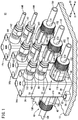
FIG. 1 is a schematic perspective view showing the entirety of a fluid control system; -
FIG. 2 is a schematic perspective view of the entirety of a first air-operated valve of the fluid control system; -
FIG. 3 is a schematic plan view of the fluid control system; -
FIG. 4 is a schematic longitudinal cross section of the first air-operated valve; -
FIG. 5 is a schematic perspective view of important part in a state where a first nut has been removed from a valve body; -
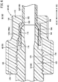
FIG. 6 is an enlarged view showing important part ofFIG. 4 ; -
FIG. 7 is a schematic perspective view of important part illustrating a nut turning tool (first tool), in a state where its arc-shaped attachment portion (small semicircular ring) for applying torque to a small-diameter tube portion is to be fitted around the small-diameter tube portion; -
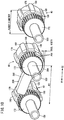
FIG. 8 is a schematic perspective view of important part, in a state where a second tool is being used to tighten (retighten or make tighter) a fitting nut of a conventional technique whose outer diameter is substantially constant along its longitudinal direction; -
FIG. 9 is a schematic front view of important part illustrating the state ofFIG. 8 ; -
FIG. 10 is a schematic perspective view of important part, in a state where a fitting nut (first nut) of an embodiment of the invention is being tightened (retightened or made tighter); -
FIG. 11 is a schematic front view of important part showing the state ofFIG. 10 ; -
FIG. 12 is a schematic perspective view of important part, in a state where, with the conventional fitting nuts located opposite each other, the second tool for turning is put around a pipe member between fitting nuts; -
FIG. 13 is a schematic perspective view of important part, in a state where, from the state ofFIG. 12 , the second tool has been moved and fitted around a fitting nut on one side; -
FIG. 14 is a schematic perspective view of important part, in a state where, with the fitting nuts (first nuts and second nuts) of the embodiment located opposite each other, a fitting nut (first nut) on one side is being turned; -
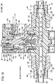
FIG. 15 is a schematic longitudinal cross section illustrating the first air-operated valve, where the first air-operate valve has been brought from the state ofFIG. 4 to an opened state by a valve portion separating from a valve seat; -
FIG. 16 is a schematic perspective view illustrating the entirety of a fluid control system including positioning and fixing members (end plates) having no tabs; -
FIG. 17 is a front view of important part, in a state where, in the structure shown inFIG. 16 , the fitting nuts shown inFIG. 8 are used and the fitting nut in the center is being turned by the second tool; and -
FIG. 18 is a front view of important part, in a state where, in the structure shown inFIG. 16 , the first nuts are used and the first nut in the center is being turned by the first tool. - Now, the fluid pressure device and the fluid control system according to the present invention will be described in detail referring to the accompanying drawings, in connection with preferred embodiments illustrating the fittings including the fitting nuts and attached to the fluid pressure device, the nut turning tool for turning the fitting nut, and the fitting nut turning method using the same. It should be noted that, in the description below, terms like "downward" and "upward", which particularly correspond to the downward direction and upward direction in
FIGS. 4 and15 , are used only for convenience in order to facilitate understanding. Such terms are not intended to specify directions in practical use of the fluid pressure device. It should also be noted that the pipes in which fluid or pilot fluid flows are all shown in cross section. - First, a
fluid control system 10 shown inFIG. 1 will be described. Thefluid control system 10 includes first to third air-operatedvalves 14a to 14c that are positioned and fixed on abase 12. The first to third air-operatedvalves 14a to 14c are air pressure devices (fluid pressure devices) that operate using compressed air as pilot fluid, and function as flow rate control valves for controlling the flow rates of fluids such as high-purity medical fluids, ultrapure water, etc. - The first to third air-operated
valves 14a to 14c are configured as so-called normally-closed valves that are closed when pilot pressure does not act. When the first to third air-operatedvalves 14a to 14c are in an opened state, the fluids flow from the A1 side to the A2 side. The direction from A1 to A2 will hereinafter be referred to also as "flow direction". Accordingly, the wording "the upstream side of the flow direction" indicates the A1 side and "the downstream side of the flow direction" indicates the A2 side. - The first air-operated
valve 14a will now be described. As shown in the overall schematic perspective view ofFIG. 2 , the first air-operatedvalve 14a includes an end plate 20 (positioning and fixing member), avalve body 22, afirst housing 24, and asecond housing 26 in this order from the side of the base 12 (certain member). The first air-operatedvalve 14a has a vertically oriented, substantially rectangular parallelepiped shape, in which theend plate 20, thevalve body 22, thefirst housing 24, and thesecond housing 26 are connected on the same axis line. Theend plate 20, thevalve body 22, thefirst housing 24, and thesecond housing 26 are all made of resin material. Preferred examples of the resin material include chemical-resistant and heat-resistant fluorine compound resins, such as polytetrafluoroethylene, polyvinylidene fluoride, perfluoroalkoxy alkane, etc. - As shown in
FIG. 3 that is a schematic plan view of thefluid control system 10, one side surface of theend plate 20 of the first air-operatedvalve 14a has afirst tab 28 protruding along a B1 direction that is perpendicular to the flow direction. Thefirst tab 28 is provided integrally with theend plate 20 in a position shifted to the A2 side. Further, the other side surface on the back of that one surface has asecond tab 30 protruding along a B2 direction that is opposite to the B1 direction. Thesecond tab 30 is provided integrally with theend plate 20 in a position shifted to the A1 side. That is, thefirst tab 28 and thesecond tab 30 protrude in the opposite directions in point-symmetrical positions of theend plate 20. Thefirst tabs 28 and thesecond tabs 30 are thus arranged in a so-called zigzag fashion. - The
first tab 28 and thesecond tab 30 respectively have a firstelongated hole 32 and a secondelongated hole 34 as through holes extending along their thickness direction. Threaded portions of mountingscrews 36 are passed respectively through the firstelongated hole 32 and the secondelongated hole 34, and the threaded portions are screwed into threaded holes formed in thebase 12, whereby the first air-operatedvalve 14a is positioned and fixed on thebase 12. - A
first nut 40 and asecond nut 42, being the fitting nuts of the embodiment, are attached respectively to the A1-side end surface and A2-side end surface of thevalve body 22, thereby forming a firstfitting portion 44 and a second fitting portion 46 (both are fittings). The firstfitting portion 44 and the secondfitting portion 46 will be described later. -
FIG. 4 is a schematic longitudinal cross section of the first air-operatedvalve 14a, andFIG. 5 is a schematic perspective view of important part illustrating a state where thefirst nut 40 has been removed from thevalve body 22. As shown inFIGS. 4 and5 , thevalve body 22 has a firstjoint body 48 protruding from its A1-side end surface and a secondjoint body 50 protruding from its A2-side end surface. The firstjoint body 48 extends on the A1 side and the secondjoint body 50 extends on the A2 side. That is, the firstjoint body 48 and the secondjoint body 50 extend along the flow direction. Needless to say, the firstjoint body 48 and the secondjoint body 50 are formed integrally with thevalve body 22. In other words, the firstjoint body 48 and the secondjoint body 50 are part of thevalve body 22 and therefore made of resin material. - As shown in
FIG. 4 , aninlet passage 52, avalve chamber 54, and anoutlet passage 56 are formed in the interior of thevalve body 22. Theinlet passage 52 extends from the end of the firstjoint body 48 on the A1 side to thevalve chamber 54, and is opened into thevalve chamber 54. Avalve seat 58 is provided in the vicinity of the opening. On the other hand, theoutlet passage 56 extends from thevalve chamber 54 to the end of the secondjoint body 50 on the A2 side. That is, theinlet passage 52 and theoutlet passage 56 communicate with each other through thevalve chamber 54. - In the interior of the
valve body 22, afirst tube wall 60 surrounding thevalve seat 58 to form thevalve chamber 54, and asecond tube wall 62 surrounding thefirst tube wall 60, extend toward thefirst housing 24. A ring-shapedgroove 64 is formed between thefirst tube wall 60 and thesecond tube wall 62. The outer edge of adiaphragm 66 is inserted in the ring-shapedgroove 64. Avalve portion 68 protrudes toward thevalve seat 58, from a radially central area of the lower surface of thediaphragm 66. When thevalve portion 68 is seated on thevalve seat 58, the communication between theinlet passage 52 and thevalve chamber 54 is cut off. Further, from the radially central area of the upper surface of thediaphragm 66, a substantially cylindrical engagingprotrusion 70 protrudes toward thefirst housing 24. - The A1-side end and the A2-side end of the outer peripheral walls of the
second tube wall 62 integrally connect to the outer walls of thevalve body 22 that form a substantially rectangular shape. - From the lower surface of the
first housing 24, which faces thevalve body 22, a ring-shapedprotrusion 72 protrudes in a position opposite to thefirst tube wall 60. The ring-shapedprotrusion 72 is inserted inside thesecond tube wall 62 and holds the outer edge of thediaphragm 66 together with thefirst tube wall 60. By this, thediaphragm 66 is held by thevalve body 22 and thefirst housing 24. On the other hand, from the upper surface of thefirst housing 24 that faces thesecond housing 26, a ring-shapedengagement portion 74 having a larger diameter than the ring-shapedprotrusion 72 protrudes. - The
first housing 24 is a hollow body and its inner chamber is sectioned by apartition 76 into alower chamber 80 and anupper chamber 82. The horizontal cross sections of thelower chamber 80 and theupper chamber 82, taken along the flow direction, are substantially perfect circles, and theupper chamber 82 has a larger diameter than thelower chamber 80. Thelower chamber 80 and thevalve chamber 54 are divided by thediaphragm 66. In other words, thediaphragm 66 cuts off the communication between thelower chamber 80 and thevalve chamber 54. A breathingport 84 communicating with thelower chamber 80 is formed in the A2-side end surface of thefirst housing 24. On the other hand, in the A1-side end surface of thefirst housing 24, afirst pilot port 86 communicating with theupper chamber 82 is formed. - A first
guide tube portion 88 is integrally formed with thepartition 76, the lower and upper ends of the firstguide tube portion 88 protruding in thelower chamber 80 and theupper chamber 82, respectively. The firstguide tube portion 88 is a cylindrical portion having afirst guide hole 90 extending therethrough along its axial direction. - A second
guide tube portion 92 and athird tube wall 94 protrude into thesecond housing 26 from the inner surface of the ceiling wall of thesecond housing 26. A ring-shapedfirst recess 96 is formed between the secondguide tube portion 92 and thethird tube wall 94. Further, a ring-shapedsecond recess 98 is formed between thethird tube wall 94 and the substantially rectangular outer walls of thesecond housing 26. Most part of areturn spring 100 is accommodated in thefirst recess 96. On the other hand, the ring-shapedengagement portion 74 is inserted in thesecond recess 98. Further, asecond pilot port 102 is formed in the A1-side end surface of thesecond housing 26. Thefirst recess 96 and thesecond pilot port 102 communicate with each other through acommunication passage 104 passing through thethird tube wall 94. - The
first housing 24 and thesecond housing 26 accommodate avalve rod 110 that is integrally formed with apiston portion 108. The lower end of thereturn spring 100 rests on the upper end surface of thepiston portion 108, to thereby resiliently bias thevalve rod 110 in the direction toward thevalve seat 58 at all times. As will be described later, thevalve rod 110 is displaced as thepiston portion 108 receives pressure (pilot pressure) of the pilot fluid. Some clearance is formed between the relatively long side wall of thepiston portion 108 and the inner wall of theupper chamber 82, but the clearance between the two walls is sealed by a ring-shapedseal member 126. - The
valve rod 110 includes afirst shaft portion 112 protruding from the lower end surface of thepiston portion 108, asecond shaft portion 114 protruding from the upper end surface of thepiston portion 108, and athird shaft portion 116 having a smaller diameter, connected to thesecond shaft portion 114 and extending to the ceiling wall of thesecond housing 26. Thefirst shaft portion 112 has anengaging hole 118 that is depressed toward thepiston portion 108. The above-mentionedengaging protrusion 70 as part of thediaphragm 66 is fitted in the engaginghole 118. This fitting allows thediaphragm 66 to be held by thevalve rod 110 through the engagingprotrusion 70. - The
first shaft portion 112 is inserted in thefirst guide hole 90 formed in the firstguide tube portion 88 that is part of thefirst housing 24. On the other hand, thesecond shaft portion 114 and thethird shaft portion 116 are inserted in asecond guide hole 120 formed in the secondguide tube portion 92 that is part of thesecond housing 26. Since thesecond guide hole 120 is opened in the ceiling wall of thesecond housing 26, a worker or user who operates thefluid control system 10 can visually recognize thethird shaft portion 116 in thesecond guide hole 120 when he or she views the first air-operatedvalve 14a in plan view (seeFIG. 3 ). When the first air-operatedvalve 14a is in the closed state, the top surface of thethird shaft portion 116 and the top surface of the ceiling wall of thesecond housing 26 are substantially flush with each other. - The
valve rod 110 is displaced with thefirst shaft portion 112 being held by the firstguide tube portion 88 and with thesecond shaft portion 114 being held by the secondguide tube portion 92. In addition, the side wall of thepiston portion 108 extends along the inner peripheral wall of theupper chamber 82 in a large area, and the clearance between the two walls is small. It is therefore possible to avoid the situation where the axial direction of thevalve rod 110 is inclined with respect to the axial direction of the first air-operatedvalve 14a. Needless to say, when thevalve rod 110 is displaced, thefirst shaft portion 112 is guided by the firstguide tube portion 88 and thesecond shaft portion 114 is guided by the secondguide tube portion 92. - As the
valve rod 110 is displaced, the engagingprotrusion 70 of thediaphragm 66 is pushed or pulled by thefirst shaft portion 112. Thediaphragm 66 is therefore displaced in the same direction as thevalve rod 110. With the displacement, thevalve portion 68 of thediaphragm 66 is seated on or separated from thevalve seat 58. That is, theinlet passage 52 and thevalve chamber 54 are cut off from each other or made to communicate with each other, and the first air-operatedvalve 14a is brought into the closed state or the opened state. -
Reference numerals FIG. 4 indicate ring-shaped seal members. Further, theend plate 20 has screw tightening holes (not shown) formed in its four corners, and thevalve body 22, thefirst housing 24, and thesecond housing 26 have rod insertion holes (not shown) formed in their four corners. Tie rods (not shown) are inserted from the rod insertion holes of thesecond housing 26, and threaded portions of the tie rods are screwed into the screw tightening holes. Theend plate 20, thevalve body 22, thefirst housing 24, and thesecond housing 26 are thus fastened together. - Rubber caps 134 (see
FIGS. 1 to 3 ) are press fitted in the rod insertion holes of thesecond housing 26. By the rubber caps 134, the rod insertion holes and the screw tightening holes are closed and kept gas-tight or liquid-tight. That is, the rubber caps 134 prevent entry of foreign matter, such as dust, liquid, etc., into the rod insertion holes and the screw tightening holes. Further, since the tie rods made of metal are sealed by the rubber caps 134, the tie rods are protected from moisture and liquid. That is, this effectively prevents corrosion of the tie rods due to adhesion of moisture or liquid. In addition, even if foreign matter like corrosion powder, metal powder, etc. generates from the tie rods, the foreign matter is sealed in the rod insertion holes by the rubber caps 134. This eliminates the fear of mixing of the foreign matter into the fluid etc. - As shown in
FIG. 1 , a first supply/discharge pipe 144 and a second supply/discharge pipe 146 (both are pilot fluid passage pipes) are connected to thefirst pilot port 86 and thesecond pilot port 102 through a first joint 140 and a second joint 142, respectively. Specifically, thefirst pilot port 86 and thesecond pilot port 102 each have a female thread formed on the inner peripheral wall thereof, and the first joint 140 and the second joint 142 each have a male thread formed on the outer peripheral wall thereof. The male thread is engaged with the female thread, whereby the first supply/discharge pipe 144 and the second supply/discharge pipe 146 are held by thefirst housing 24 and thesecond housing 26 through the first joint 140 and the second joint 142, respectively. - When the first to third air-operated
valves 14a to 14c are configured as normally-closed valves as described above, it is not essential to attach the second supply/discharge pipes 146 to thesecond pilot ports 102. For example, thesecond pilot ports 102 may be closed by plug members. - Next, the first
fitting portion 44 and the secondfitting portion 46 provided in thevalve body 22 will be described. - As shown in
FIG. 5 , andFIG. 6 which is an enlarged view of important part inFIG. 4 , the firstfitting portion 44 includes the firstjoint body 48 protruding from the A1-side end surface of thevalve body 22, and thefirst nut 40, where the firstjoint body 48 and thefirst nut 40 hold a fluid supply pipe 150 (pipe member) therebetween. Needless to say, the interior of thefluid supply pipe 150 communicates with theinlet passage 52 in the firstjoint body 48. - The first
joint body 48 includes a cylindricalproximal portion 152 having a relatively large diameter and integrally connected to thevalve body 22. Amale thread 154 is formed on the outer peripheral wall of theproximal portion 152. - The first
joint body 48 further includes a cylindricalextended shaft portion 156 having a relatively small diameter and protruding to the A1 side from theproximal portion 152. Atapered surface 158 whose diameter gradually expands from the A1 side toward the A2 side is formed at the end of theextended shaft portion 156. - On the outer peripheral surface of the
extended shaft portion 156, a plurality of ring-shapedprotrusions 164 are formed in an area on the A2 side of the taperedsurface 158, the ring-shapedprotrusions 164 abutting on the inner wall surface of a diameter-increasedportion 150a of thefluid supply pipe 150. The plurality of ring-shapedprotrusions 164 each have a top having a substantially triangular cross section, and are arranged at certain intervals along the axial direction of theextended shaft portion 156. The ring-shapedprotrusions 164 have substantially the same height.FIGS. 5 and6 show an example in which five ring-shapedprotrusions 164 are provided, but the number of the ring-shapedprotrusions 164 is not particularly limited to this. Only a single ring-shapedprotrusion 164 may be provided, for example. - On the other hand, the
first nut 40 includes a large-diameter tube portion 170 having a relatively large diameter, and a small-diameter tube portion 172 that is contiguous to the large-diameter tube portion 170 and that protrudes to the A1 side. Needless to say, the small-diameter tube portion 172 has a smaller diameter than the large-diameter tube portion 170. The large-diameter tube portion 170 and the small-diameter tube portion 172 are both formed as hollow tubes. Accordingly, the large-diameter tube portion 170 has a firstinner hole 174 therein and the small-diameter tube portion 172 has a secondinner hole 176 therein. The inner diameter of the firstinner hole 174 is set larger than that of the secondinner hole 176. - Then, the inner peripheral wall forming the first
inner hole 174 of the large-diameter portion 170 has formed thereon afemale thread 178 that engages with themale thread 154 of the firstjoint body 48. The outer peripheral wall of the large-diameter tube portion 170 has formed thereon a plurality ofengagement protrusions 180 protruding outward in the diameter direction of the large-diameter tube portion 170 (seeFIGS. 1 to 3 ). Accordingly, the maximum outer diameter portion of thefirst nut 40, where its outer diameter defined as the distance from the center to the outer circumference is maximum, is the area where each of theengagement protrusions 180 is formed. Eachengagement protrusion 180 extends along a direction orthogonal to the diameter direction, i.e., along the longitudinal direction (flow direction) of the large-diameter tube portion 170. In this case, sixengagement protrusions 180 are provided and spaced apart from each other at substantially equal intervals. - An
insertion hole 182 having a circular cross section is formed in the A1-side end surface (end surface) of the small-diameter tube portion 172, and thefluid supply pipe 150 is inserted in theinsertion hole 182. Further, a ring-shapedpressing portion 184, which forms an acute angle in cross section, is formed on the inner peripheral wall of the small-diameter tube portion 172. When thefirst nut 40 is tightened on the firstjoint body 48, the ring-shapedpressing portion 184 presses the inclined outer peripheral surface of thefluid supply pipe 150 against the taperedsurface 158. - The second
inner hole 176 has a larger diameter than theinsertion hole 182. The inner peripheral wall forming the secondinner hole 176 is spaced apart at a certain interval from the ring-shapedprotrusions 164 on theextended shaft portion 156 of the firstjoint body 48. The distance between the tops of the ring-shapedprotrusions 164 and the inner peripheral wall is smaller than the thickness of the diameter-increasedportion 150a of thefluid supply pipe 150 at the time of the formation of the diameter-increasedportion 150a. - On the outer peripheral wall of the small-
diameter tube portion 172, a plurality of ridges protrude outward in the diameter direction of the small-diameter tube portion 172. The number of the ridges is larger than the number of theengagement protrusions 180 on the outer peripheral wall of the large-diameter tube portion 170. Each ridge extends along the longitudinal direction (flow direction) that is orthogonal to the diameter direction of the small-diameter tube portion 172. Accordingly,engagement grooves 186, which are depressed inwardly in the diameter direction of the small-diameter tube portion 172 and extend along the longitudinal direction orthogonal to the diameter direction, are formed between adjacent ridges. The ridges and theengagement grooves 186 alternate along the circumferential direction of the small-diameter tube portion 172, so that the outer peripheral wall of the small-diameter tube portion 172 is formed like so-called straight teeth. - The
first nut 40 constructed as described above is made of a resin material like the valve body 22 (joint body). In the same way, thefluid supply pipe 150 is also made of a resin material. Preferred examples of the resin materials include fluorine compound resins listed earlier. - The second
fitting portion 46 disposed in the A2-side end surface of thevalve body 22 includes the secondjoint body 50, thesecond nut 42, and afluid discharge pipe 188 that are configured in the same manner respectively as the firstjoint body 48, thefirst nut 40, and thefluid supply pipe 150. The secondfitting portion 46 will therefore be not described in detail. Concerning the secondjoint body 50 and thesecond nut 42, "A1" in the description of the firstjoint body 48 and thefirst nut 40 is replaced by "A2". The diameter-increased portion of thefluid discharge pipe 188 is labeled withreference numeral 188a (seeFIG. 6 ). - The remaining second and third air-operated
valves valve 14a. Accordingly, the same constituent components are labeled with the same reference numerals and will not be described in detail. -
FIG. 7 shows afirst tool 200, which is a nut turning tool according to the embodiment, and applies torque to the small-diameter tube portion 172 to turn the first nut 40 (or the second nut 42). Thefirst tool 200 includes asmall handle 202 as a shaft, and a small semicircular ring 204 (arc-shaped attachment portion) which is formed of an arc-shaped, thin, curved plate and has a substantially semicircular form. Thesmall handle 202 has larger rigidity than the smallsemicircular ring 204. - The small
semicircular ring 204 has a shape such that a ring body is cut into a substantially semicircular shape, i.e., an arc-like shape. Anopening 205 is therefore formed in the smallsemicircular ring 204. Further, the smallsemicircular ring 204, formed of a thin curved plate, has superior elasticity. That is, when an external force acts on theopening 205 and theopening 205 is expanded, theopening 205 easily closes when the external force disappears. That is, the smallsemicircular ring 204 returns to its original shape. - Further, the inner wall of the small
semicircular ring 204 has formed thereon three engagement claws 206 (claws) protruding inwardly in the diameter direction, i.e., toward the first nut 40 (or the second nut 42). The inner diameter of the smallsemicircular ring 204 substantially matches the outer diameter of the small-diameter tube portion 172 of thefirst nut 40 and thesecond nut 42. The pitch or phase difference betweenadjacent engagement claws 206 is substantially equal to the pitch or phase difference betweenadjacent engagement grooves 186. The threeengagement claws 206 can thus engage with threeengagement grooves 186. -
FIG. 7 shows an example in which threeengagement claws 206 are provided, but the number of theengagement claws 206 is not particularly limited to this, so long as it is one or more. That is, two orless engagement claws 206, or four ormore engagement claws 206 may be provided. -
FIG. 8 shows asecond tool 210 that can apply torque to the large-diameter tube portion 170. Thesecond tool 210 includes alarge handle 212 that is thicker and longer than thesmall handle 202, and a largesemicircular ring 214 whose inner diameter is larger than that of the smallsemicircular ring 204 and that is somewhat longer than the semicircle. The largesemicircular ring 214 has anopening 215, and includes fiveengagement recesses 216 formed in its inner wall and depressed outward in its diameter direction. The inner diameter of the largesemicircular ring 214 substantially matches the outer diameter of the large-diameter tube portions 170 of thefirst nut 40 and thesecond nut 42. The pitch or phase difference between adjacent engagement recesses 216 is substantially equal to the pitch or phase difference betweenadjacent engagement protrusions 180. Accordingly, the fiveengagement recesses 216 can engage with fiveengagement protrusions 180. - While
FIG. 8 shows an example in which the number of theengagement protrusions 180 is six (the phase difference between theengagement protrusions 180 is about 60°) and the number of the engagement recesses 216 is five, the numbers of theengagement protrusions 180 and the engagement recesses 216 are not particularly limited to this example. For instance, even if sixengagement protrusions 180 are provided as in this example, four or less engagement recesses 216 may be provided. Further, five or less, or six ormore engagement protrusions 180 may be provided, with four or less, or six or more engagement recesses 216. - The
first tool 200 and thesecond tool 210 are both made of resin material. Examples of the resin material include fluorine compound resins, such as polytetrafluoroethylene, polyvinylidene fluoride, perfluoroalkoxy alkane, etc., but may be other resin material. Specific examples of other resin material include polypropylene, polyethylene, etc. - According to the embodiment, the
first nut 40 and the second nut 42 (fitting nuts), the firstfitting portion 44 and the secondfitting portion 46, the first to third air-operatedvalves 14a to 14c (fluid pressure devices), thefluid control system 10 including the same, and thefirst tool 200, are constructed basically as described so far. Next, their functions and effects will be described in connection with a method for turning the fitting nuts (thefirst nut 40 and the second nut 42) that is performed in the process of assembling thefluid control system 10. - In order to fabricate the
fluid control system 10, first, the first to third air-operatedvalves 14a to 14c are positioned and fixed on thebase 12. For this purpose, the threaded portions of the mountingscrews 36 are inserted respectively in the firstelongated holes 32 of thefirst tabs 28 and the secondelongated holes 34 of thesecond tabs 30 of the first to third air-operatedvalves 14a to 14c, and the threaded portions are temporarily screwed respectively into the threaded holes formed in thebase 12. At this stage, the first to third air-operatedvalves 14a to 14c can be displaced along the longitudinal direction of the firstelongated holes 32 and the second elongated holes 34. That is, the positions of the first to third air-operatedvalves 14a to 14c can be adjusted. After that, the mountingscrews 36 are retightened (made tighter). - Since the
first tabs 28 and thesecond tabs 30 are arranged in a zigzag fashion (seeFIG. 3 ), thesecond tab 30 of the first air-operatedvalve 14a and thefirst tab 28 of the second air-operatedvalve 14b, for example, are arranged in a row on the upstream side (A1 side) and the downstream side (A2 side) of the flow direction. That is, thesecond tab 30 of the first air-operatedvalve 14a is not arranged in a row along the B1 direction or B2 direction with thefirst tab 28 or thesecond tab 30 of the second air-operatedvalve 14b. Accordingly, it is possible to set the distance between thevalve bodies 22 of the first and second air-operatedvalves second tab 30 of the first air-operatedvalve 14a in the B2 direction (or the protruding length of thefirst tab 28 of the second air-operatedvalve 14b in the B1 direction). - Consequently, the first air-operated
valve 14a and the second air-operatedvalve 14b can be located most closely. The same applies to the second air-operatedvalve 14b and the third air-operatedvalve 14c. Thefluid control system 10 can be made compact for this reason. - In
FIG. 3 , the side of the first to third air-operatedvalves 14a to 14c on which thefirst pilot ports 86 and thesecond pilot ports 102 are located is the fluid inlet side, and the other side is the fluid outlet side, but this is merely an example. A configuration may be adopted in which, in at least one of the first to third air-operatedvalves 14a to 14c, the side on which thefirst pilot port 86 and thesecond pilot port 102 are located is the fluid outlet side and the other side is the fluid inlet side. - Next, the first supply/
discharge pipe 144 is connected into thefirst pilot port 86 through the first joint 140, and the second supply/discharge pipe 146 is connected into thesecond pilot port 102 through thesecond joint 142. The first supply/discharge pipe 144 and the second supply/discharge pipe 146 may be connected respectively into thefirst pilot port 86 and thesecond pilot port 102 before positioning and fixing the first to third air-operatedvalves 14a to 14c on thebase 12. - Next, the first
fitting portion 44 is assembled. Specifically, first, the end of thefluid supply pipe 150 is inserted into theinsertion hole 182 of thefirst nut 40, and the end of thefluid supply pipe 150 is pulled by a given length to the large-diameter tube portion 170 side. Then, the firstjoint body 48 is inserted into the hollow interior of the end. - The
extended shaft portion 156 of the firstjoint body 48 is inserted into the large-diameter tube portion 170 of thefirst nut 40, and thefemale thread 178 of thefirst nut 40 is screwed along themale thread 154 of the firstjoint body 48. That is, thefirst nut 40 is tightened. Thefirst nut 40 may be first manually tightened by the worker and then retightened after that, for example. - As the
first nut 40 is tightened, the diameter of thefluid supply pipe 150 is expanded gradually from the end along the taperedsurface 158 of theextended shaft portion 156. Also, the inner peripheral wall of the small-diameter tube portion 172 of thefirst nut 40 and theextended shaft portion 156 of the firstjoint body 48 gradually overlap along the axial direction. As a result, the plurality of ring-shapedprotrusions 164 on theextended shaft portion 156 gradually face the inner peripheral wall forming the secondinner hole 176 of the small-diameter tube portion 172, starting from the side close to the taperedsurface 158. The inner peripheral wall facing the ring-shapedprotrusions 164 presses the outer wall surface of the expandedfluid supply pipe 150 against the ring-shapedprotrusions 164. - That is, the
fluid supply pipe 150 is first expanded by theextended shaft portion 156 and then deformed while being squeezed sequentially from the side close to the taperedsurface 158. In this way, the inner peripheral wall of the diameter-increasedportion 150a is compressed in the areas thereof in contact with the ring-shapedprotrusions 164, while being swelled inwardly in the diameter direction on both sides thereof and entering the spaces between adjacent ring-shapedprotrusions 164. - The diameter-increased
portion 150a of thefluid supply pipe 150 is formed in this way, and the diameter-increasedportion 150a is thus held between the plurality of ring-shapedprotrusions 164 of theextended shaft portion 156 and the inner peripheral wall of the small-diameter tube portion 172 of thefirst nut 40. That is, the inner peripheral wall of the diameter-increasedportion 150a comes in close contact with the plurality of ring-shapedprotrusions 164. A seal is thus provided between the ends of the ring-shapedprotrusions 164 and the inner wall surface of the diameter-increasedportion 150a. - Then, as the
first nut 40 is further screwed by manual tightening or retightening, thefluid supply pipe 150 is pinched and pressed between thetapered surface 158 of theextended shaft portion 156 and the ring-shapedpressing portion 184 of thefirst nut 40. As a result, thetapered surface 158 comes in close contact with the inclined inner wall surface of thefluid supply pipe 150 that is pressed by the inner peripheral wall of the small-diameter tube portion 172. A seal is thus provided also between thetapered surface 158 and the inclined inner wall surface of thefluid supply pipe 150. - Now,
FIGS. 8 and9 show fitting nuts 230 according to a conventional technique, one of which is being retightened. In order to facilitate visual recognition and understanding,FIG. 8 omits thevalve bodies 22,first housings 24, etc., and theengagement protrusions 180 are labeled with the same reference numeral as theengagement protrusions 180 of thefirst nut 40. Also, the outer diameter of thefitting nuts 230 is the same as the outer diameter of the large-diameter tube portion 170 of thefirst nut 40 and substantially constant along the longitudinal direction of thefitting nut 230. - As explained earlier, the first to third air-operated
valves 14a to 14c are arranged in a row. Accordingly, thefitting nuts 230 of the first to third air-operatedvalves 14a to 14c are arranged in a row from the B1 side to the B2 side. -
FIGS. 8 and9 show an example in which thefitting nut 230 of the second air-operatedvalve 14b is retightened by thesecond tool 210. In this case, as can be seen also referring toFIG. 17 , engaging the engagement recesses 216 of thesecond tool 210 with theengagement protrusions 180 and turning thefitting nut 230 requires that a pitch P1 between the adjacentfitting nuts 230 be set not less than the sum of the tool width and the outer diameter of the maximum outer diameter portion of the fitting nut 230 (the distance from the center of thefitting nut 230 to the outer circumferential surfaces of the engagement protrusions 180). This is because, if the pitch P1 is less than the sum, thefitting nuts 230 interfere with the largesemicircular ring 214 as thesecond tool 210 is moved along the longitudinal direction of the fitting nuts 230. - Hence, the first air-operated
valve 14a and the second air-operatedvalve 14b, and the second air-operatedvalve 14b and the third air-operatedvalve 14c, cannot be located so close that the pitch P1 becomes less than the sum of the outer diameter of the maximum outer diameter portion of thefitting nut 230 and the tool width. That is, in this case, it is difficult to locate the first to third air-operatedvalves 14a to 14c most closely as explained earlier. - Furthermore, as shown in
FIG. 9 , when thefitting nut 230 is turned, the first joint 140 and the first supply/discharge pipe 144 interfere with thelarge handle 212 of thesecond tool 210 while a turning angle θ1 is relatively small. In this case, the largesemicircular ring 214 is once removed from thefitting nut 230, thelarge handle 212 is returned to the position before being turned, and the engagement recesses 216 is engaged with theengagement protrusions 180 again to turn thefitting nut 230 again. However, the retightening work will be troublesome if this work has to be repeated many times. - Furthermore, if the turning angle θ1 is less than the phase difference between adjacent engagement protrusions 180 (60° in the example in which the six
engagement protrusions 180 are provided), then thefitting nut 230 of the first air-operatedvalve 14a may interfere with thelarge handle 212 when engaging the engagement recesses 216 with theengagement protrusions 180 again. In this case, engaging the engagement recesses 216 with theengagement protrusions 180 again itself is difficult. - In contrast, in the embodiment, as shown in
FIGS. 10 and11 , since the small-diameter tube portions 172 are smaller in diameter than the large-diameter tube portions 170, relatively large clearance is formed between adjacent small-diameter tube portions 172 even when the large-diameter tube portions 170 of thefirst nuts 40 are located most closely. When the worker retightens thefirst nut 40 of the second air-operatedvalve 14b, the worker inserts the smallsemicircular ring 204 of thefirst tool 200 into the clearance and then causes the small-diameter tube portion 172 to enter theopening 205 of the smallsemicircular ring 204. Since the smallsemicircular ring 204 has superior elasticity, theopening 205 of the smallsemicircular ring 204 is easily expanded. It is thus easy to cause the small-diameter tube portion 172 to enter theopening 205. - At substantially the same time as the small-
diameter tube portion 172 enters theopening 205, the expandedopening 205 closes due to the elasticity of the smallsemicircular ring 204. At substantially the same time or before that, the threeengagement claws 206 formed on the inner wall of the smallsemicircular ring 204 are engaged respectively with three of theengagement grooves 186. Thefirst tool 200 is thus attached to (fitted around) the small-diameter tube portion 172 without coming off from the small-diameter tube portion 172. In this state, the worker turns thesmall handle 202 to apply torque to the small-diameter tube portion 172, to thereby integrally turn the small-diameter tube portion 172 and the large-diameter tube portion 170 that is continuous to the small-diameter tube portion 172. Since the rigidity of thesmall handle 202 is larger than that of the smallsemicircular ring 204, the torque is efficiently transmitted from thesmall handle 202 to the small-diameter tube portion 172. - In this way, according to the embodiment in which the
first nut 40 has the small-diameter tube portion 172, thefirst nut 40 can be turned even when the large-diameter tube portions 170 are located most closely. That is, depending on the circumstances, particularly as shown inFIGS. 16 and18 , a pitch P2 between adjacentfirst nuts 40 can be set substantially equal to the outer diameter of the maximum outer diameter portion of the first nut 40 (the distance from the center of the large-diameter tube portion 170 to the outer surfaces of the engagement protrusions 180). Consequently, the first to third air-operatedvalves 14a to 14c can be arranged in a row most closely as has been explained above. - Furthermore, as shown in
FIG. 11 , because the outer diameter of the small-diameter tube portion 172 is smaller than that of the large-diameter tube portion 170, the turning angle θ2, from the position at which turning of the small-diameter tube portion 172 of thefirst nut 40 is started to the position at which the first joint 140 and the first supply/discharge pipe 144 interfere with thesmall handle 202 of thefirst tool 200, is larger than the turning angle θ1. Thus, thefirst nut 40 can be turned through a larger angle by applying torque to the small-diameter tube portion 172 one time. When the first joint 140 and the first supply/discharge pipe 144 interfere with thesmall handle 202, the smallsemicircular ring 204 is once removed from the small-diameter tube portion 172, thesmall handle 202 is returned to the position before being turned, and theengagement claws 206 are engaged with theengagement grooves 186 again, to turn thefirst nut 40 again. Thus, because the turning angle θ2 in one turning of thefirst nut 40 can be made larger, thefirst nut 40 can be tightened by turning it a reduced number of times. - Furthermore, because the pitch or phase difference between
adjacent engagement grooves 186 is smaller, it is possible to effectively avoid the situation where thefirst nut 40 of the first air-operatedvalve 14a interferes with thesmall handle 202 during reengagement of theengagement claws 206 with theengagement grooves 186. Theengagement claws 206 can thus be re-engaged with theengagement grooves 186 easily. For these reasons, the work of retightening can be easily achieved even if the turning angle θ2 is small. - The second
fitting portion 46 can be assembled by tightening thesecond nut 42 around the secondjoint body 50 in the same manner. Since thefirst pilot port 86 and thesecond pilot port 102 are not provided on the side of the second fitting portion 46 (on the A2 side), there is no fear that thefirst tool 200 or thesecond tool 210 is interfered with by the first joint 140, the first supply/discharge pipe 144, etc., whichever of thefirst tool 200 and thesecond tool 210 is used. In such a case, thesecond nut 42 may be turned by using thesecond tool 210. - Specifically, the five
engagement recesses 216 formed in the inner wall of the largesemicircular ring 214 of thesecond tool 210 are engaged with five of theengagement protrusions 180 formed on the outer peripheral wall of the large-diameter tube portion 170 of thesecond nut 42 in the same manner as shown inFIG. 8 . Torque is then applied to the large-diameter tube portion 170 through thelarge handle 212. The large-diameter tube portion 170 and the small-diameter tube portion 172 that is continuous to the large-diameter tube portion 170 are thus turned integrally. - In this way, because of the formation of the
engagement protrusions 180 on the outer peripheral walls of the large-diameter tube portions 170 of thefirst nut 40 and thesecond nut 42, thefirst nut 40 and thesecond nut 42 can not only be turned through the application of torque to the small-diameter tube portion 172 by means of thefirst tool 200, but can also be turned through the application of torque to the large-diameter tube portion 170 by means of thesecond tool 210. In the latter case, larger torque can be applied compared to when the small-diameter tube portion 172 is turned. This provides the advantage that the retightening work of thefirst nuts 40 and the second nuts 42 can be achieved easily in situations where the pipe members or the like are not provided densely and thesecond tool 210 can be easily turned. - That is, the formation of the
engagement grooves 186 around the small-diameter tube portion 172 and theengagement protrusions 180 around the large-diameter tube portion 170 enables selective use of thefirst tool 200 and thesecond tool 210. Hence, when supply/discharge pipes etc. interfere with thesecond tool 210, then thefirst tool 200 can be used to reliably turn the small-diameter tube portion 172 even in a small space, while thesecond tool 210 can be used to apply larger torque to the large-diameter tube portion 170 when there is no fear that supply/discharge pipes etc. interfere with thesecond tool 210. - Incidentally, some fluid control device may be disposed on the upstream side (or the downstream side) of the first to third air-operated
valves 14a to 14c. As shown inFIG. 12 , according to conventional techniques, if the fluid control device is located close to the first to third air-operatedvalves 14a to 14c along the flow direction, then thefitting nuts 230 of the fluid control device are positioned opposite to thefitting nuts 230 of the first to third air-operatedvalves 14a to 14c. Since thesecond tool 210 is thick and has a large tool width, its elasticity (flexibility) is poor. The opening of the largesemicircular ring 214 is therefore hardly expandable. Hence, in this state, it is difficult to fit the largesemicircular ring 214 directly around thefitting nut 230 of the second air-operatedvalve 14b, for example. - Accordingly, when retightening the
fitting nut 230 of the second air-operatedvalve 14b, first (seeFIG. 12 ), the largesemicircular ring 214 is put around thefluid supply pipe 150 that is exposed between thefitting nut 230 of the fluid control device and the oppositefitting nut 230 of the second air-operatedvalve 14b. Subsequently, as shown inFIG. 13 , thesecond tool 210 has to be moved to the fitting nut 230 (to the A2 side) of the second air-operatedvalve 14b. The engagement recesses 216 of thesecond tool 210 thus engage with theengagement protrusions 180 of thefitting nut 230. - In contrast, as shown in
FIG. 14 , when the fluid control device includes thesecond nuts 42 and the first to third air-operatedvalves 14a to 14c include thefirst nuts 40, and the fluid control device and the first to third air-operatedvalves 14a to 14c are located close to each other along the flow direction, then the small-diameter tube portions 172 of thesecond nuts 42 and the small-diameter tube portions 172 of thefirst nuts 40 face each other. Since thefirst tool 200 is thin and has a smaller tool width, its elasticity (flexibility) is relatively large. Accordingly, theopening 205 of the smallsemicircular ring 204 easily expands when fitting the smallsemicircular ring 204 around the small-diameter tube portion 172. It is therefore easy to cause the small-diameter tube portion 172 to enter theopening 205. - Furthermore, after the small
semicircular ring 204 has been fitted around the small-diameter tube portion 172, theopening 205 closes due to its elasticity. Also, theengagement claws 206 engage with theengagement grooves 186. Thefirst tool 200 is thus attached to the small-diameter tube portion 172. It is thus possible to fit the smallsemicircular ring 204 directly around the small-diameter tube portion 172 of thefirst nut 40 of the second air-operatedvalve 14b and then to turn thefirst nut 40 by applying torque to the small-diameter tube portion 172. - It is therefore not necessary to expose the
fluid supply pipe 150 between thesecond nut 42 attached to the fluid control device and the oppositefirst nut 40 of the second air-operatedvalve 14b. Depending on the circumstances, the downstream end surfaces of thesecond nuts 42 and the upstream end surfaces of thefirst nuts 40 can be abutted against each other. This allows the fluid control device and the first to third air-operatedvalves 14a to 14c to be located closer to each other, which enables thefluid control system 10 to be made further compact, or in other words to be more integrated. - The first to third air-operated
valves 14a to 14c operate as follows to control the flow rates of fluids. - When bringing the first air-operated
valve 14a (or the second air-operatedvalve 14b or the third air-operatedvalve 14c) into the opened state to cause high-purity medical fluid or ultrapure water to flow, pilot air is supplied from the first supply/discharge pipe 144 into theupper chamber 82 through thefirst pilot port 86. This increases the internal pressure in theupper chamber 82, and thepiston portion 108 of thevalve rod 110 is pressed by the pilot air from its lower surface. As a result, as shown inFIG. 15 , thevalve rod 110 is displaced to thesecond housing 26 side (i.e., upward inFIGS. 4 and15 ) by the amount corresponding to the pilot pressure of the pilot air. At this time, thefirst shaft portion 112 and thesecond shaft portion 114 forming thevalve rod 110 and protruding from thepiston portion 108 are guided by the inner peripheral walls of thefirst guide hole 90 and thesecond guide hole 120. Further, the outer peripheral wall of thepiston portion 108 slides along the inner peripheral wall of theupper chamber 82. Further, thereturn spring 100 is pressed by thepiston portion 108 and compressed. - As the
valve rod 110 is displaced upward, thediaphragm 66, whose engagingprotrusion 70 is fitted in the engaginghole 118 of thefirst shaft portion 112, is displaced in the same direction as the valve rod 110 (i.e., upward). Thevalve portion 68 of thediaphragm 66 thus separates away from thevalve seat 58. As thediaphragm 66 is displaced upward, the internal volume of thelower chamber 80 decreases and so the air in thelower chamber 80 is discharged from the breathingport 84. - As the
valve portion 68 separates away from thevalve seat 58, theinlet passage 52 and thevalve chamber 54 communicate with each other, and theinlet passage 52 and theoutlet passage 56 also communicate with each other through thevalve chamber 54. Then, the fluid that has reached theinlet passage 52 through thefluid supply pipe 150 is introduced into thevalve chamber 54 and flows into thefluid discharge pipe 188 from thevalve chamber 54 through theoutlet passage 56. The high-purity medical fluid or ultrapure water is thus supplied to the manufacturing apparatus, processing apparatus, or the like. - When the first to third air-operated
valves 14a to 14c are in the opened state, the upper end of thethird shaft portion 116 is exposed from thesecond guide hole 120. The worker or user visually recognizes the exposedthird shaft portion 116 to know that the first to third air-operatedvalves 14a to 14c are in the opened state. - When stopping the flow of the fluid like high-purity medical fluid, ultrapure water, etc., the
valve portion 68 is seated on thevalve seat 58. That is, the supply of pilot air from the first supply/discharge pipe 144 is stopped. Further, the pilot air in theupper chamber 82 is discharged through thefirst pilot port 86. The discharge reduces the internal pressure in theupper chamber 82, and then the resilient force of thereturn spring 100 exceeds the internal pressure in theupper chamber 82. As a result, thereturn spring 100 stretches to resiliently bias thepiston portion 108 toward thefirst housing 24. Thevalve rod 110 including thepiston portion 108 is thus displaced downward to return to the original position. - This displacement increases the internal volume of the
lower chamber 80, causing the air to be introduced into thelower chamber 80 through the breathingport 84. Alternatively, thesecond pilot port 102 may be configured to function as a breathing port. In this case, it is not particularly necessary to attach the second supply/discharge pipe 146 to thesecond pilot port 102. Needless to say, thefirst shaft portion 112 and thesecond shaft portion 114 are guided by the inner peripheral walls of thefirst guide hole 90 and thesecond guide hole 120 also when thevalve rod 110 is displaced downward. - As the
valve rod 110 is returned to the original position (is displaced downward), thediaphragm 66 is displaced downward integrally with thevalve rod 110 and thevalve portion 68 thereof is seated on thevalve seat 58. This cuts off the communication between theinlet passage 52 and theoutlet passage 56 through thevalve chamber 54. That is, the fluid in theinlet passage 52 is prevented from flowing downstream past thevalve chamber 54. - When the first to third air-operated
valves 14a to 14c are brought into the closed state, the upper end of thethird shaft portion 116 returns into thesecond guide hole 120. The worker or user visually recognizes that the top surface of thethird shaft portion 116 has become substantially flush with the top surface of the ceiling wall of thesecond housing 26, to know that the first to third air-operatedvalves 14a to 14c have returned to the closed state. - The present invention is not particularly limited to the embodiments described above and can be modified in various manners without departing from the essence and gist of the present invention.
- For example, the fluid pressure device may be configured to use working oil as pilot fluid. The fluid pressure device may be a device other than a flow rate control valve, such as an actuator, etc.
- Further, while in this embodiment, the fittings for connecting the pipe members in which the fluid subjected to flow rate control flows include the
first nuts 40 and the second nuts 42, the fittings for connecting the first supply/discharge pipe 144 and the second supply/discharge pipe 146 to thefirst pilot port 86 and thesecond pilot port 102 may include thefirst nuts 40 and the second nuts 42. - Further, the
first pilot port 86 and thesecond pilot port 102 may be arranged in a row with the secondjoint body 50. - Furthermore, as shown in
FIG. 16 , anend plate 250 may be constructed without thefirst tab 28 and thesecond tab 30. In this case, threaded holes (not shown) are formed in the lower surface of theend plate 250 and elongated holes (not shown) are formed through thebase 12, and mounting screws (not shown) are inserted respectively into the elongated holes and screwed in the threaded holes. In this case, the absence of thefirst tab 28 and thesecond tab 30 allows the first air-operatedvalve 14a and the second air-operatedvalve 14b, and the second air-operatedvalve 14b and the third air-operatedvalve 14c, to be located closer. - With this configuration, as shown in
FIG. 17 , when thefitting nuts 230 of the conventional technique are used, a pitch P1' between adjacentfitting nuts 230 can be set smaller than the pitch P1 inFIG. 8 . However, in this case, too, it is necessary to ensure that the pitch P1' is not less than the sum of the outer diameter of the fitting nut 230 (the outer diameter of the large-diameter tube portion 170) and the tool width of thesecond tool 210. Accordingly, it may be not possible to most closely locate the first air-operatedvalve 14a and the second air-operatedvalve 14b, and the second air-operatedvalve 14b and the third air-operatedvalve 14c. - In contrast, as shown in
FIG. 18 , when the first nuts 40 (or the second nuts 42) are used, relatively large clearance is formed between adjacent small-diameter tube portions 172. When turning the first nut 40 (or the second nut 42), the smallsemicircular ring 204 of thefirst tool 200 can be inserted in the clearance and fitted around the small-diameter tube portion 172 as explained earlier. - Accordingly, in this case, too, it is possible to set a pitch P2' between adjacent first nuts 40 (or adjacent second nuts 42) to be substantially equivalent to the outer diameter of the large-
diameter tube portion 170. It is therefore possible to make thefluid control system 10 compact by omitting thefirst tab 28 and thesecond tab 30 and most closely locating the first air-operatedvalve 14a and the second air-operatedvalve 14b, and the second air-operatedvalve 14b and the third air-operatedvalve 14c. - Needless to say, in the configuration shown in
FIG. 18 , the first nut 40 (or the second nut 42) can be easily tightened by engaging theengagement claws 206 of thefirst tool 200 with theengagement grooves 186 formed around the small-diameter tube portion 172 of the first nut 40 (or the second nut 42). - The first to third air-operated
valves 14a to 14c may be constructed as normally-opened valves. In this case, thereturn spring 100 is provided on the lower surface side of thepiston portion 108 so as to resiliently bias thepiston portion 108 toward thesecond housing 26. While the second supply/discharge pipe 146 is attached to thesecond pilot port 102, thefirst pilot port 86 may be closed by a plug member. - Alternatively, the first to third air-operated
valves 14a to 14c may be constructed as so-called double-acting valves. In this case, the first to third air-operatedvalves 14a to 14c are brought into the opened state by supplying pilot fluid from thefirst pilot port 86 into theupper chamber 82, while the first to third air-operatedvalves 14a to 14c are brought into the closed state by supplying pilot fluid into thesecond housing 26 from thesecond pilot port 102. It is therefore not particularly necessary to incorporate thereturn spring 100 in this configuration.
Claims (18)
- A fitting nut (40, 42) made of a resin material and having a female thread (178) that is engaged with a male thread (154) formed on an outer peripheral wall of a joint body (48, 50) made of a resin material, the fitting nut comprising:a large-diameter tube portion (170) that is hollow and includes the female thread formed on an inner peripheral wall thereof; anda small-diameter tube portion (172) that is continuous to the large-diameter tube portion, has a hollow cylindrical shape with a smaller diameter than the large-diameter tube portion and includes, in an end surface thereof, an insertion hole (182) in which a pipe member (150) is inserted,wherein the small-diameter tube portion includes a plurality of engagement grooves (186) formed in an outer peripheral wall thereof, the plurality of engagement grooves being depressed inwardly in a diameter direction of the small-diameter tube portion and extending along a longitudinal direction that is orthogonal to the diameter direction.
- The fitting nut according to claim 1, wherein the large-diameter tube portion has a plurality of engagement protrusions (180) formed on an outer peripheral wall thereof, the plurality of engagement protrusions protruding outwardly in a diameter direction of the large-diameter tube portion and extending along a longitudinal direction that is orthogonal to the diameter direction.
- A fitting (44, 46) comprising:a fitting nut (40, 42) made of a resin material and having a female thread (178) formed thereon; anda joint body (48, 50) made of a resin material and having, on an outer peripheral wall thereof, a male thread (154) that is engaged with the female thread,wherein the fitting nut includesa large-diameter tube portion (170) that is hollow and includes the female thread formed on an inner peripheral wall thereof, anda small-diameter tube portion (172) that is continuous to the large-diameter tube portion, has a hollow cylindrical shape with a smaller diameter than the large-diameter tube portion and includes, in an end surface thereof, an insertion hole (182) in which a pipe member (150) is inserted, andthe small-diameter tube portion includes a plurality of engagement grooves (186) formed in an outer peripheral wall thereof, the plurality of engagement grooves being depressed inwardly in a diameter direction of the small-diameter tube portion and extending along a longitudinal direction that is orthogonal to the diameter direction.
- The fitting according to claim 3, wherein the large-diameter tube portion of the fitting nut includes a plurality of engagement protrusions (180) formed on an outer peripheral wall thereof, the plurality of engagement protrusions protruding outwardly in a diameter direction of the large-diameter tube portion and extending along a longitudinal direction that is orthogonal to the diameter direction.
- A fluid pressure device (14a to 14c) in which a fluid supply pipe (150) configured to supply a fluid, a fluid discharge pipe (188) configured to discharge the fluid, and a pilot fluid passage pipe (144, 146) configured to allow a pilot fluid to flow therethrough, are connected respectively through fittings (44, 46),
wherein at least one of the fittings includes a fitting nut (40, 42) made of a resin material and having a female thread (178) formed thereon, and a joint body (48, 50) made of a resin material and having, on an outer peripheral wall thereof, a male thread (154) that is engaged with the female thread,
the fitting nut includes
a large-diameter tube portion (170) that is hollow and includes the female thread formed on an inner peripheral wall thereof, and
a small-diameter tube portion (172) that is continuous to the large-diameter tube portion, has a hollow cylindrical shape with a smaller diameter than the large-diameter tube portion and includes, in an end surface thereof, an insertion hole (182) in which the fluid supply pipe, the fluid discharge pipe, or the pilot fluid passage pipe is inserted, and
the small-diameter tube portion includes a plurality of engagement grooves (186) formed in an outer peripheral wall thereof, the plurality of engagement grooves being depressed inwardly in a diameter direction of the small-diameter tube portion and extending along a longitudinal direction that is orthogonal to the diameter direction. - The fluid pressure device according to claim 5, wherein the large-diameter tube portion of the fitting nut includes a plurality of engagement protrusions (180) formed on an outer peripheral wall thereof, the plurality of engagement protrusions protruding outwardly in a diameter direction of the large-diameter tube portion and extending along a longitudinal direction that is orthogonal to the diameter direction.
- The fluid pressure device according to claim 5 or 6, wherein the fluid supply pipe or the fluid discharge pipe, and the pilot fluid passage pipe are arranged in a row.
- The fluid pressure device according to any one of claims 5 to 7, further comprising a positioning and fixing member (20) that is positioned and fixed on a certain member,
wherein the positioning and fixing member includes, on point-symmetrical positions thereof, a first tab (28) and a second tab (30) protruding in opposite directions and each having a through hole formed along a thickness direction thereof. - A fluid control system (10) comprising at least two fluid pressure devices (14a to 14c) that are arranged adjacent to each other in a row,
wherein, in each of the fluid pressure devices, a fluid supply pipe (150) configured to supply a fluid, a fluid discharge pipe (188) configured to discharge the fluid, and a pilot fluid passage pipe (144, 146) configured to allow a pilot fluid to flow therethrough, are connected respectively through fittings (44, 46),
at least one of the fittings includes a fitting nut (40, 42) made of a resin material and having a female thread (178) formed thereon, and a joint body (48, 50) made of a resin material and having, on an outer peripheral wall thereof, a male thread (154) that is engaged with the female thread,
the fitting nut includes
a large-diameter tube portion (170) that is hollow and includes the female thread formed on an inner peripheral wall thereof, and
a small-diameter tube portion (172) that is continuous to the large-diameter tube portion, has a hollow cylindrical shape with a smaller diameter than the large-diameter tube portion and includes, in an end surface thereof, an insertion hole (182) in which the fluid supply pipe, the fluid discharge pipe, or the pilot fluid passage pipe is inserted, and
the small-diameter tube portion includes a plurality of engagement grooves (186) formed in an outer peripheral wall thereof, the plurality of engagement grooves being depressed inwardly in a diameter direction of the small-diameter tube portion and extending along a longitudinal direction that is orthogonal to the diameter direction. - The fluid control system according to claim 9, wherein the large-diameter tube portion of each of the fitting nuts includes a plurality of engagement protrusions (180) formed on an outer peripheral wall thereof, the plurality of engagement protrusions protruding outwardly in a diameter direction of the large-diameter tube portion and extending along a longitudinal direction that is orthogonal to the diameter direction.
- The fluid control system according to claim 9 or 10, wherein, in each of the fluid pressure devices, the fluid supply pipe or the fluid discharge pipe, and the pilot fluid passage pipe are arranged in a row.
- The fluid control system according to any one of claims 9 to 11, wherein each of the fluid pressure devices further include a positioning and fixing member (20) that is positioned and fixed on a certain member, and
the positioning and fixing member includes, on point-symmetrical positions thereof, a first tab (28) and a second tab (30) protruding in opposite directions and each having a through hole formed along a thickness direction thereof. - The fluid control system according to any one of claims 9 to 12, wherein a pitch between the fitting nut of one of the fluid pressure devices and the fitting nut of another of the fluid pressure devices that is adjacent to the one fluid pressure device is substantially equivalent to an outer diameter of a maximum outer diameter portion of the fitting nuts.
- A nut turning tool (200) for turning a nut (40, 42), the nut turning tool comprising:an arc-shaped attachment portion (204) shaped like an arc with an opening (205), the arc-shaped attachment portion being attached to the nut; anda shaft portion (202) continuous to the arc-shaped attachment portion and extending linearly,wherein the arc-shaped attachment portion includes, on an inner surface thereof, one or more claws (206) protruding toward the nut, andthe arc-shaped attachment portion exhibits elasticity in a direction in which the opening is closed after being expanded.
- The nut turning tool according to claim 14, wherein the arc-shaped attachment portion is formed of a curved plate.
- The nut turning tool according to claim 14 or 15, wherein the shaft portion has larger rigidity than the arc-shaped attachment portion.
- A fitting nut turning method for turning a fitting nut (40, 42) using a nut turning tool (200) to thereby engage the fitting nut with a joint body (48, 50) or to release the engagement with the joint body,
wherein the nut turning tool used includes
an arc-shaped attachment portion (204) shaped like an arc with an opening (205), the arc-shaped attachment portion being attached to the fitting nut, and
a shaft portion (202) continuous to the arc-shaped attachment portion and extending linearly,
the arc-shaped attachment portion includes, on an inner surface thereof, one or more claws (206) protruding toward the nut, and
the arc-shaped attachment portion exhibits elasticity in a direction in which the opening is closed after being expanded,
the fitting nut turning method comprising:causing the fitting nut to enter the opening while expanding the opening with the fitting nut;engaging the claw with an engagement groove (186) formed in an outer peripheral wall of the fitting nut, while, when the entry of the fitting nut into the opening ends, closing the opening by the elasticity of the arc-shaped attachment portion to attach the arc-shaped attachment portion to the fitting nut; andapplying thereafter torque to the fitting nut through the shaft portion to turn the fitting nut. - The fitting nut turning method according to claim 17, wherein in a case where the fitting nut includes a large-diameter tube portion (170) and a small-diameter tube portion (172), the engagement groove is formed around the small-diameter tube portion, at least two fluid pressure devices (14a to 14c) each including the fitting nut are located adjacent to each other and the fitting nuts thereof are placed adjacent to each other, and a pitch between the fitting nuts is substantially equivalent to an outer diameter of the large-diameter tube portion, then the arc-shaped attachment portion is inserted from between the small-diameter tube portions that are adjacent to each other.
Applications Claiming Priority (1)
| Application Number | Priority Date | Filing Date | Title |
|---|---|---|---|
| JP2019178168A JP7243961B2 (en) | 2019-09-30 | 2019-09-30 | Pipe joint nut, pipe joint, fluid pressure device, fluid control system, jig for nut rotation, and screwing method for pipe joint nut |
Publications (3)
| Publication Number | Publication Date |
|---|---|
| EP3798488A1 true EP3798488A1 (en) | 2021-03-31 |
| EP3798488B1 EP3798488B1 (en) | 2025-10-29 |
| EP3798488B9 EP3798488B9 (en) | 2026-02-25 |
Family
ID=72659094
Family Applications (1)
| Application Number | Title | Priority Date | Filing Date |
|---|---|---|---|
| EP20198267.5A Active EP3798488B9 (en) | 2019-09-30 | 2020-09-25 | Fitting nut, fitting, fluid pressure device, and fluid control system, and nut turning tool and fitting nut turning method |
Country Status (6)
| Country | Link |
|---|---|
| US (2) | US12565953B2 (en) |
| EP (1) | EP3798488B9 (en) |
| JP (1) | JP7243961B2 (en) |
| KR (1) | KR102799651B1 (en) |
| CN (2) | CN112576825B (en) |
| TW (1) | TWI846956B (en) |
Citations (3)
| Publication number | Priority date | Publication date | Assignee | Title |
|---|---|---|---|---|
| JP2014145396A (en) * | 2013-01-28 | 2014-08-14 | Nippon Pillar Packing Co Ltd | Pipe joint nut |
| JP2014145397A (en) * | 2013-01-28 | 2014-08-14 | Nippon Pillar Packing Co Ltd | Pipe connection device |
| JP2019148319A (en) | 2018-02-28 | 2019-09-05 | 株式会社フジキン | Screw-in joint and fluid supply system using the same |
Family Cites Families (37)
| Publication number | Priority date | Publication date | Assignee | Title |
|---|---|---|---|---|
| US2685219A (en) | 1952-03-31 | 1954-08-03 | Diebold Fritz | Open-end wrench jaws having thrust and pull surfaces of different curvature |
| US3059513A (en) | 1959-01-26 | 1962-10-23 | Dwight O Ness | Wrench |
| GB1178845A (en) * | 1966-08-18 | 1970-01-21 | Lillian Johnson | Improvements in or relating to Spanners |
| IL64379A (en) * | 1981-11-26 | 1989-01-31 | Plasson Maagan Michael Ind Ltd | Tube connection fittings |
| JPS60500096A (en) * | 1982-12-30 | 1985-01-24 | コ−ルダ− プロダクツ カンパニ− | Attachment for soft tube |
| USD329788S (en) * | 1990-05-23 | 1992-09-29 | Peter Andrew | Combination wrench for lock nuts |
| US5200575A (en) * | 1991-01-25 | 1993-04-06 | Sheehan Robert K | Connector assembly for conduit |
| JPH09189385A (en) | 1995-09-28 | 1997-07-22 | Masaru Kogyo Kk | Fittings and grip rings for fittings |
| JP4081620B2 (en) * | 1997-03-05 | 2008-04-30 | Smc株式会社 | Suck back valve |
| EP1022504B1 (en) * | 1999-01-25 | 2005-08-17 | JRG Gunzenhauser AG | Threaded coupling for pipes |
| USD461107S1 (en) * | 2001-05-21 | 2002-08-06 | Edmond Lee Pitt | Wrench for fastener |
| JP2003108261A (en) | 2001-09-27 | 2003-04-11 | Toshiba Corp | Electronic device and support leg device applied to the electronic device |
| JP4142883B2 (en) * | 2002-03-20 | 2008-09-03 | シーケーディ株式会社 | Chemical valve |
| US6745648B2 (en) * | 2002-09-23 | 2004-06-08 | Specialty Welding & Fabricating Of New York, Inc. | Lock-nut wrench |
| JP3947971B2 (en) * | 2002-11-25 | 2007-07-25 | Smc株式会社 | Pipe fitting |
| US20050150332A1 (en) * | 2004-01-13 | 2005-07-14 | Russell Lynn R. | Toilet ballcock valve wrench |
| US7340939B2 (en) * | 2004-08-25 | 2008-03-11 | Jansen's Aircraft Systems Controls, Inc. | Emissions sampling valve |
| JP2007002902A (en) * | 2005-06-22 | 2007-01-11 | Ckd Corp | Manifold structure and valve unit using the same |
| JP2008023623A (en) * | 2006-07-19 | 2008-02-07 | Sekisui Jushi Co Ltd | Wrench |
| US20080061551A1 (en) * | 2006-09-12 | 2008-03-13 | Simmons Tom M | Coupling nuts, coupling assembly including a coupling nut, and method of forming a coupling nut |
| JP4253026B2 (en) * | 2007-08-23 | 2009-04-08 | 日本ピラー工業株式会社 | Resin pipe joint and manufacturing method thereof |
| DE202008008213U1 (en) | 2008-06-20 | 2008-08-14 | Hansatronic Gmbh | key tool |
| JP4885201B2 (en) | 2008-12-01 | 2012-02-29 | 日本ピラー工業株式会社 | Resin pipe fitting |
| KR101322576B1 (en) * | 2008-12-01 | 2013-10-28 | 니폰 필라고교 가부시키가이샤 | Resin pipe joint |
| JP5297406B2 (en) | 2010-03-17 | 2013-09-25 | Ckd株式会社 | Fluid control valve |
| JP5612906B2 (en) * | 2010-05-28 | 2014-10-22 | サーパス工業株式会社 | Flow control valve |
| US9452511B2 (en) | 2010-11-24 | 2016-09-27 | Last Tool Factory Llc | Combination ER wrench |
| US8459698B2 (en) * | 2010-12-23 | 2013-06-11 | North American Specialty Products Llc | Riser cap and irrigation piping system using same |
| JP5717569B2 (en) * | 2011-07-19 | 2015-05-13 | Ckd株式会社 | Pilot type solenoid valve and solenoid valve block body |
| CN102661460A (en) * | 2012-05-22 | 2012-09-12 | 重庆界石仪表有限公司 | Pipeline corner connector and application method thereof |
| KR102094045B1 (en) * | 2013-01-28 | 2020-03-26 | 니혼삐라아코오교오카부시키가이샤 | Tube connecting device |
| CN203202479U (en) * | 2013-04-09 | 2013-09-18 | 成都工投电子设备有限公司 | Union convenient to rapidly disassemble and assemble and union spanner |
| JP5891537B2 (en) | 2014-07-07 | 2016-03-23 | Smc株式会社 | Pipe fitting |
| CN106969219A (en) * | 2017-05-18 | 2017-07-21 | 海信(山东)空调有限公司 | Pipeline connection component, spanner and air conditioner |
| CN207901011U (en) * | 2018-01-12 | 2018-09-25 | 张少东 | Combination wrench |
| CN209354827U (en) * | 2018-12-30 | 2019-09-06 | 上海文依电气股份有限公司 | Reinforced high intensity snap ring-type locks waterproof hose connector |
| EP4619944A1 (en) | 2022-11-18 | 2025-09-24 | Siemens Healthcare Diagnostics Inc. | Systems and methods for classifying blood cells |
-
2019
- 2019-09-30 JP JP2019178168A patent/JP7243961B2/en active Active
-
2020
- 2020-09-21 US US17/026,396 patent/US12565953B2/en active Active
- 2020-09-24 TW TW109133129A patent/TWI846956B/en active
- 2020-09-25 EP EP20198267.5A patent/EP3798488B9/en active Active
- 2020-09-28 CN CN202011038931.2A patent/CN112576825B/en active Active
- 2020-09-28 KR KR1020200125846A patent/KR102799651B1/en active Active
- 2020-09-28 CN CN202311429003.2A patent/CN117307837A/en active Pending
-
2024
- 2024-04-11 US US18/632,692 patent/US12553553B2/en active Active
Patent Citations (3)
| Publication number | Priority date | Publication date | Assignee | Title |
|---|---|---|---|---|
| JP2014145396A (en) * | 2013-01-28 | 2014-08-14 | Nippon Pillar Packing Co Ltd | Pipe joint nut |
| JP2014145397A (en) * | 2013-01-28 | 2014-08-14 | Nippon Pillar Packing Co Ltd | Pipe connection device |
| JP2019148319A (en) | 2018-02-28 | 2019-09-05 | 株式会社フジキン | Screw-in joint and fluid supply system using the same |
Also Published As
| Publication number | Publication date |
|---|---|
| CN112576825B (en) | 2024-04-26 |
| CN112576825A (en) | 2021-03-30 |
| KR20210038365A (en) | 2021-04-07 |
| US20210095801A1 (en) | 2021-04-01 |
| US20240255082A1 (en) | 2024-08-01 |
| EP3798488B1 (en) | 2025-10-29 |
| KR102799651B1 (en) | 2025-04-28 |
| JP2021055724A (en) | 2021-04-08 |
| US12565953B2 (en) | 2026-03-03 |
| US12553553B2 (en) | 2026-02-17 |
| TWI846956B (en) | 2024-07-01 |
| TW202122703A (en) | 2021-06-16 |
| EP3798488B9 (en) | 2026-02-25 |
| CN117307837A (en) | 2023-12-29 |
| JP7243961B2 (en) | 2023-03-22 |
Similar Documents
| Publication | Publication Date | Title |
|---|---|---|
| CN105276307B (en) | Pipe joint | |
| KR102204817B1 (en) | Pipe joint made of synthetic resin | |
| US11493156B2 (en) | Hammerless and torqueless union connection | |
| TW201727126A (en) | Non-terminating double closure fittings | |
| IL259255A (en) | Flow control valve and complementary adjustment tool set | |
| US12553553B2 (en) | Nut turning tool and fitting nut turning method | |
| JP2006161873A (en) | Connection structure of integrated panel with fluid device | |
| EP1803983A1 (en) | Structure for connection between integrated panel and fluid device | |
| EP1909001A1 (en) | Connection structure between integrated panel and fluid device | |
| JP2006083972A (en) | Connection structure of mutual flange pipes and connection construction of flange pipe and fluid apparatus | |
| EP1881253A1 (en) | Structure for connection between integrated panel and fluid device | |
| EP1909017A1 (en) | Connection structure of stack panel to fluid device | |
| JP4393472B2 (en) | Connection structure between fluid devices | |
| JP4324576B2 (en) | Connection structure between fluid devices | |
| JP2002048416A (en) | Bathtub piping connection device | |
| WO2020044727A1 (en) | Flow passage joint structure | |
| JP4654013B2 (en) | Connection structure between integrated panel and fluidic device | |
| JP4512526B2 (en) | Connection structure between integrated panel and fluidic device | |
| JP2006161830A (en) | Connection structure between flange piping and connection structure between flange piping and fluid equipment | |
| KR200255541Y1 (en) | pipe for liquid connecting device of ball valve | |
| CN101027517A (en) | Structure for connection between integrated panel and fluid device | |
| JP4557932B2 (en) | Connection structure between fluid devices | |
| JP7175701B2 (en) | Flow joint structure | |
| CN101171450A (en) | Connection structure of integrated board and fluidic device | |
| JPH0875071A (en) | Fixed structure of cartridge type port joint of supply / discharge port |
Legal Events
| Date | Code | Title | Description |
|---|---|---|---|
| PUAI | Public reference made under article 153(3) epc to a published international application that has entered the european phase |
Free format text: ORIGINAL CODE: 0009012 |
|
| STAA | Information on the status of an ep patent application or granted ep patent |
Free format text: STATUS: THE APPLICATION HAS BEEN PUBLISHED |
|
| AK | Designated contracting states |
Kind code of ref document: A1 Designated state(s): AL AT BE BG CH CY CZ DE DK EE ES FI FR GB GR HR HU IE IS IT LI LT LU LV MC MK MT NL NO PL PT RO RS SE SI SK SM TR |
|
| AX | Request for extension of the european patent |
Extension state: BA ME |
|
| STAA | Information on the status of an ep patent application or granted ep patent |
Free format text: STATUS: REQUEST FOR EXAMINATION WAS MADE |
|
| 17P | Request for examination filed |
Effective date: 20210929 |
|
| RBV | Designated contracting states (corrected) |
Designated state(s): AL AT BE BG CH CY CZ DE DK EE ES FI FR GB GR HR HU IE IS IT LI LT LU LV MC MK MT NL NO PL PT RO RS SE SI SK SM TR |
|
| STAA | Information on the status of an ep patent application or granted ep patent |
Free format text: STATUS: EXAMINATION IS IN PROGRESS |
|
| 17Q | First examination report despatched |
Effective date: 20221011 |
|
| GRAP | Despatch of communication of intention to grant a patent |
Free format text: ORIGINAL CODE: EPIDOSNIGR1 |
|
| STAA | Information on the status of an ep patent application or granted ep patent |
Free format text: STATUS: GRANT OF PATENT IS INTENDED |
|
| RAP3 | Party data changed (applicant data changed or rights of an application transferred) |
Owner name: SMC CORPORATION |
|
| INTG | Intention to grant announced |
Effective date: 20250521 |
|
| GRAS | Grant fee paid |
Free format text: ORIGINAL CODE: EPIDOSNIGR3 |
|
| GRAA | (expected) grant |
Free format text: ORIGINAL CODE: 0009210 |
|
| STAA | Information on the status of an ep patent application or granted ep patent |
Free format text: STATUS: THE PATENT HAS BEEN GRANTED |
|
| AK | Designated contracting states |
Kind code of ref document: B1 Designated state(s): AL AT BE BG CH CY CZ DE DK EE ES FI FR GB GR HR HU IE IS IT LI LT LU LV MC MK MT NL NO PL PT RO RS SE SI SK SM TR |
|
| REG | Reference to a national code |
Ref country code: CH Ref legal event code: F10 Free format text: ST27 STATUS EVENT CODE: U-0-0-F10-F00 (AS PROVIDED BY THE NATIONAL OFFICE) Effective date: 20251029 Ref country code: GB Ref legal event code: FG4D |
|
| REG | Reference to a national code |
Ref country code: IE Ref legal event code: FG4D |
|
| REG | Reference to a national code |
Ref country code: DE Ref legal event code: R096 Ref document number: 602020061130 Country of ref document: DE |
|
| REG | Reference to a national code |
Ref country code: CH Ref legal event code: Q17 Free format text: ST27 STATUS EVENT CODE: U-0-0-Q10-Q17 (AS PROVIDED BY THE NATIONAL OFFICE) Effective date: 20260128 |
|
| REG | Reference to a national code |
Ref country code: NL Ref legal event code: MP Effective date: 20251029 |
|
| PG25 | Lapsed in a contracting state [announced via postgrant information from national office to epo] |
Ref country code: ES Free format text: LAPSE BECAUSE OF FAILURE TO SUBMIT A TRANSLATION OF THE DESCRIPTION OR TO PAY THE FEE WITHIN THE PRESCRIBED TIME-LIMIT Effective date: 20251029 |
|
| REG | Reference to a national code |
Ref country code: LT Ref legal event code: MG9D |
|
| PG25 | Lapsed in a contracting state [announced via postgrant information from national office to epo] |
Ref country code: NO Free format text: LAPSE BECAUSE OF FAILURE TO SUBMIT A TRANSLATION OF THE DESCRIPTION OR TO PAY THE FEE WITHIN THE PRESCRIBED TIME-LIMIT Effective date: 20260129 |
|
| PG25 | Lapsed in a contracting state [announced via postgrant information from national office to epo] |
Ref country code: HR Free format text: LAPSE BECAUSE OF FAILURE TO SUBMIT A TRANSLATION OF THE DESCRIPTION OR TO PAY THE FEE WITHIN THE PRESCRIBED TIME-LIMIT Effective date: 20251029 Ref country code: AT Free format text: LAPSE BECAUSE OF FAILURE TO SUBMIT A TRANSLATION OF THE DESCRIPTION OR TO PAY THE FEE WITHIN THE PRESCRIBED TIME-LIMIT Effective date: 20251029 Ref country code: FI Free format text: LAPSE BECAUSE OF FAILURE TO SUBMIT A TRANSLATION OF THE DESCRIPTION OR TO PAY THE FEE WITHIN THE PRESCRIBED TIME-LIMIT Effective date: 20251029 |
|
| REG | Reference to a national code |
Ref country code: AT Ref legal event code: MK05 Ref document number: 1851877 Country of ref document: AT Kind code of ref document: T Effective date: 20251029 |
|
| PG25 | Lapsed in a contracting state [announced via postgrant information from national office to epo] |
Ref country code: NL Free format text: LAPSE BECAUSE OF FAILURE TO SUBMIT A TRANSLATION OF THE DESCRIPTION OR TO PAY THE FEE WITHIN THE PRESCRIBED TIME-LIMIT Effective date: 20251029 |
|
| PG25 | Lapsed in a contracting state [announced via postgrant information from national office to epo] |
Ref country code: RS Free format text: LAPSE BECAUSE OF FAILURE TO SUBMIT A TRANSLATION OF THE DESCRIPTION OR TO PAY THE FEE WITHIN THE PRESCRIBED TIME-LIMIT Effective date: 20260129 |
|
| PG25 | Lapsed in a contracting state [announced via postgrant information from national office to epo] |
Ref country code: IS Free format text: LAPSE BECAUSE OF FAILURE TO SUBMIT A TRANSLATION OF THE DESCRIPTION OR TO PAY THE FEE WITHIN THE PRESCRIBED TIME-LIMIT Effective date: 20260228 |
|
| PG25 | Lapsed in a contracting state [announced via postgrant information from national office to epo] |
Ref country code: PT Free format text: LAPSE BECAUSE OF FAILURE TO SUBMIT A TRANSLATION OF THE DESCRIPTION OR TO PAY THE FEE WITHIN THE PRESCRIBED TIME-LIMIT Effective date: 20260302 |
|
| PG25 | Lapsed in a contracting state [announced via postgrant information from national office to epo] |
Ref country code: PL Free format text: LAPSE BECAUSE OF FAILURE TO SUBMIT A TRANSLATION OF THE DESCRIPTION OR TO PAY THE FEE WITHIN THE PRESCRIBED TIME-LIMIT Effective date: 20251029 |
|
| PG25 | Lapsed in a contracting state [announced via postgrant information from national office to epo] |
Ref country code: LV Free format text: LAPSE BECAUSE OF FAILURE TO SUBMIT A TRANSLATION OF THE DESCRIPTION OR TO PAY THE FEE WITHIN THE PRESCRIBED TIME-LIMIT Effective date: 20251029 |
|
| PG25 | Lapsed in a contracting state [announced via postgrant information from national office to epo] |
Ref country code: BG Free format text: LAPSE BECAUSE OF FAILURE TO SUBMIT A TRANSLATION OF THE DESCRIPTION OR TO PAY THE FEE WITHIN THE PRESCRIBED TIME-LIMIT Effective date: 20251029 |