EP3798478B1 - Method to control the execution of a downshift with a released accelerator pedal in a drivetrain provided with a dual-clutch, servo-assisted transmission - Google Patents
Method to control the execution of a downshift with a released accelerator pedal in a drivetrain provided with a dual-clutch, servo-assisted transmission Download PDFInfo
- Publication number
- EP3798478B1 EP3798478B1 EP20199328.4A EP20199328A EP3798478B1 EP 3798478 B1 EP3798478 B1 EP 3798478B1 EP 20199328 A EP20199328 A EP 20199328A EP 3798478 B1 EP3798478 B1 EP 3798478B1
- Authority
- EP
- European Patent Office
- Prior art keywords
- instant
- clutch
- internal combustion
- combustion engine
- gear
- Prior art date
- Legal status (The legal status is an assumption and is not a legal conclusion. Google has not performed a legal analysis and makes no representation as to the accuracy of the status listed.)
- Active
Links
- 230000005540 biological transmission Effects 0.000 title claims description 33
- 238000000034 method Methods 0.000 title claims description 28
- 238000002485 combustion reaction Methods 0.000 claims description 67
- 230000003213 activating effect Effects 0.000 claims 1
- 230000001133 acceleration Effects 0.000 description 12
- 230000007423 decrease Effects 0.000 description 4
- 238000010586 diagram Methods 0.000 description 4
- 230000003247 decreasing effect Effects 0.000 description 2
- 239000002184 metal Substances 0.000 description 2
- 230000002829 reductive effect Effects 0.000 description 2
- 230000004044 response Effects 0.000 description 2
- 230000001934 delay Effects 0.000 description 1
- 230000000694 effects Effects 0.000 description 1
- 238000009434 installation Methods 0.000 description 1
- 230000000670 limiting effect Effects 0.000 description 1
- 230000036961 partial effect Effects 0.000 description 1
- 230000004043 responsiveness Effects 0.000 description 1
- 230000002441 reversible effect Effects 0.000 description 1
- 230000001360 synchronised effect Effects 0.000 description 1
Images


Classifications
-
- B—PERFORMING OPERATIONS; TRANSPORTING
- B60—VEHICLES IN GENERAL
- B60W—CONJOINT CONTROL OF VEHICLE SUB-UNITS OF DIFFERENT TYPE OR DIFFERENT FUNCTION; CONTROL SYSTEMS SPECIALLY ADAPTED FOR HYBRID VEHICLES; ROAD VEHICLE DRIVE CONTROL SYSTEMS FOR PURPOSES NOT RELATED TO THE CONTROL OF A PARTICULAR SUB-UNIT
- B60W30/00—Purposes of road vehicle drive control systems not related to the control of a particular sub-unit, e.g. of systems using conjoint control of vehicle sub-units, or advanced driver assistance systems for ensuring comfort, stability and safety or drive control systems for propelling or retarding the vehicle
- B60W30/18—Propelling the vehicle
- B60W30/19—Improvement of gear change, e.g. by synchronisation or smoothing gear shift
-
- F—MECHANICAL ENGINEERING; LIGHTING; HEATING; WEAPONS; BLASTING
- F16—ENGINEERING ELEMENTS AND UNITS; GENERAL MEASURES FOR PRODUCING AND MAINTAINING EFFECTIVE FUNCTIONING OF MACHINES OR INSTALLATIONS; THERMAL INSULATION IN GENERAL
- F16H—GEARING
- F16H61/00—Control functions within control units of change-speed- or reversing-gearings for conveying rotary motion ; Control of exclusively fluid gearing, friction gearing, gearings with endless flexible members or other particular types of gearing
- F16H61/68—Control functions within control units of change-speed- or reversing-gearings for conveying rotary motion ; Control of exclusively fluid gearing, friction gearing, gearings with endless flexible members or other particular types of gearing specially adapted for stepped gearings
- F16H61/684—Control functions within control units of change-speed- or reversing-gearings for conveying rotary motion ; Control of exclusively fluid gearing, friction gearing, gearings with endless flexible members or other particular types of gearing specially adapted for stepped gearings without interruption of drive
- F16H61/688—Control functions within control units of change-speed- or reversing-gearings for conveying rotary motion ; Control of exclusively fluid gearing, friction gearing, gearings with endless flexible members or other particular types of gearing specially adapted for stepped gearings without interruption of drive with two inputs, e.g. selection of one of two torque-flow paths by clutches
-
- B—PERFORMING OPERATIONS; TRANSPORTING
- B60—VEHICLES IN GENERAL
- B60W—CONJOINT CONTROL OF VEHICLE SUB-UNITS OF DIFFERENT TYPE OR DIFFERENT FUNCTION; CONTROL SYSTEMS SPECIALLY ADAPTED FOR HYBRID VEHICLES; ROAD VEHICLE DRIVE CONTROL SYSTEMS FOR PURPOSES NOT RELATED TO THE CONTROL OF A PARTICULAR SUB-UNIT
- B60W10/00—Conjoint control of vehicle sub-units of different type or different function
- B60W10/02—Conjoint control of vehicle sub-units of different type or different function including control of driveline clutches
-
- B—PERFORMING OPERATIONS; TRANSPORTING
- B60—VEHICLES IN GENERAL
- B60W—CONJOINT CONTROL OF VEHICLE SUB-UNITS OF DIFFERENT TYPE OR DIFFERENT FUNCTION; CONTROL SYSTEMS SPECIALLY ADAPTED FOR HYBRID VEHICLES; ROAD VEHICLE DRIVE CONTROL SYSTEMS FOR PURPOSES NOT RELATED TO THE CONTROL OF A PARTICULAR SUB-UNIT
- B60W10/00—Conjoint control of vehicle sub-units of different type or different function
- B60W10/04—Conjoint control of vehicle sub-units of different type or different function including control of propulsion units
- B60W10/06—Conjoint control of vehicle sub-units of different type or different function including control of propulsion units including control of combustion engines
-
- B—PERFORMING OPERATIONS; TRANSPORTING
- B60—VEHICLES IN GENERAL
- B60W—CONJOINT CONTROL OF VEHICLE SUB-UNITS OF DIFFERENT TYPE OR DIFFERENT FUNCTION; CONTROL SYSTEMS SPECIALLY ADAPTED FOR HYBRID VEHICLES; ROAD VEHICLE DRIVE CONTROL SYSTEMS FOR PURPOSES NOT RELATED TO THE CONTROL OF A PARTICULAR SUB-UNIT
- B60W10/00—Conjoint control of vehicle sub-units of different type or different function
- B60W10/10—Conjoint control of vehicle sub-units of different type or different function including control of change-speed gearings
- B60W10/11—Stepped gearings
- B60W10/113—Stepped gearings with two input flow paths, e.g. double clutch transmission selection of one of the torque flow paths by the corresponding input clutch
-
- F—MECHANICAL ENGINEERING; LIGHTING; HEATING; WEAPONS; BLASTING
- F16—ENGINEERING ELEMENTS AND UNITS; GENERAL MEASURES FOR PRODUCING AND MAINTAINING EFFECTIVE FUNCTIONING OF MACHINES OR INSTALLATIONS; THERMAL INSULATION IN GENERAL
- F16D—COUPLINGS FOR TRANSMITTING ROTATION; CLUTCHES; BRAKES
- F16D48/00—External control of clutches
- F16D48/06—Control by electric or electronic means, e.g. of fluid pressure
-
- F—MECHANICAL ENGINEERING; LIGHTING; HEATING; WEAPONS; BLASTING
- F16—ENGINEERING ELEMENTS AND UNITS; GENERAL MEASURES FOR PRODUCING AND MAINTAINING EFFECTIVE FUNCTIONING OF MACHINES OR INSTALLATIONS; THERMAL INSULATION IN GENERAL
- F16H—GEARING
- F16H61/00—Control functions within control units of change-speed- or reversing-gearings for conveying rotary motion ; Control of exclusively fluid gearing, friction gearing, gearings with endless flexible members or other particular types of gearing
- F16H61/04—Smoothing ratio shift
-
- F—MECHANICAL ENGINEERING; LIGHTING; HEATING; WEAPONS; BLASTING
- F16—ENGINEERING ELEMENTS AND UNITS; GENERAL MEASURES FOR PRODUCING AND MAINTAINING EFFECTIVE FUNCTIONING OF MACHINES OR INSTALLATIONS; THERMAL INSULATION IN GENERAL
- F16H—GEARING
- F16H61/00—Control functions within control units of change-speed- or reversing-gearings for conveying rotary motion ; Control of exclusively fluid gearing, friction gearing, gearings with endless flexible members or other particular types of gearing
- F16H61/26—Generation or transmission of movements for final actuating mechanisms
- F16H61/28—Generation or transmission of movements for final actuating mechanisms with at least one movement of the final actuating mechanism being caused by a non-mechanical force, e.g. power-assisted
- F16H61/2807—Generation or transmission of movements for final actuating mechanisms with at least one movement of the final actuating mechanism being caused by a non-mechanical force, e.g. power-assisted using electric control signals for shift actuators, e.g. electro-hydraulic control therefor
-
- F—MECHANICAL ENGINEERING; LIGHTING; HEATING; WEAPONS; BLASTING
- F16—ENGINEERING ELEMENTS AND UNITS; GENERAL MEASURES FOR PRODUCING AND MAINTAINING EFFECTIVE FUNCTIONING OF MACHINES OR INSTALLATIONS; THERMAL INSULATION IN GENERAL
- F16H—GEARING
- F16H63/00—Control outputs from the control unit to change-speed- or reversing-gearings for conveying rotary motion or to other devices than the final output mechanism
- F16H63/40—Control outputs from the control unit to change-speed- or reversing-gearings for conveying rotary motion or to other devices than the final output mechanism comprising signals other than signals for actuating the final output mechanisms
- F16H63/50—Signals to an engine or motor
- F16H63/502—Signals to an engine or motor for smoothing gear shifts
-
- B—PERFORMING OPERATIONS; TRANSPORTING
- B60—VEHICLES IN GENERAL
- B60W—CONJOINT CONTROL OF VEHICLE SUB-UNITS OF DIFFERENT TYPE OR DIFFERENT FUNCTION; CONTROL SYSTEMS SPECIALLY ADAPTED FOR HYBRID VEHICLES; ROAD VEHICLE DRIVE CONTROL SYSTEMS FOR PURPOSES NOT RELATED TO THE CONTROL OF A PARTICULAR SUB-UNIT
- B60W2540/00—Input parameters relating to occupants
- B60W2540/10—Accelerator pedal position
-
- B—PERFORMING OPERATIONS; TRANSPORTING
- B60—VEHICLES IN GENERAL
- B60W—CONJOINT CONTROL OF VEHICLE SUB-UNITS OF DIFFERENT TYPE OR DIFFERENT FUNCTION; CONTROL SYSTEMS SPECIALLY ADAPTED FOR HYBRID VEHICLES; ROAD VEHICLE DRIVE CONTROL SYSTEMS FOR PURPOSES NOT RELATED TO THE CONTROL OF A PARTICULAR SUB-UNIT
- B60W2540/00—Input parameters relating to occupants
- B60W2540/30—Driving style
-
- B—PERFORMING OPERATIONS; TRANSPORTING
- B60—VEHICLES IN GENERAL
- B60W—CONJOINT CONTROL OF VEHICLE SUB-UNITS OF DIFFERENT TYPE OR DIFFERENT FUNCTION; CONTROL SYSTEMS SPECIALLY ADAPTED FOR HYBRID VEHICLES; ROAD VEHICLE DRIVE CONTROL SYSTEMS FOR PURPOSES NOT RELATED TO THE CONTROL OF A PARTICULAR SUB-UNIT
- B60W2710/00—Output or target parameters relating to a particular sub-units
- B60W2710/02—Clutches
- B60W2710/021—Clutch engagement state
-
- B—PERFORMING OPERATIONS; TRANSPORTING
- B60—VEHICLES IN GENERAL
- B60W—CONJOINT CONTROL OF VEHICLE SUB-UNITS OF DIFFERENT TYPE OR DIFFERENT FUNCTION; CONTROL SYSTEMS SPECIALLY ADAPTED FOR HYBRID VEHICLES; ROAD VEHICLE DRIVE CONTROL SYSTEMS FOR PURPOSES NOT RELATED TO THE CONTROL OF A PARTICULAR SUB-UNIT
- B60W2710/00—Output or target parameters relating to a particular sub-units
- B60W2710/06—Combustion engines, Gas turbines
- B60W2710/0605—Throttle position
-
- B—PERFORMING OPERATIONS; TRANSPORTING
- B60—VEHICLES IN GENERAL
- B60W—CONJOINT CONTROL OF VEHICLE SUB-UNITS OF DIFFERENT TYPE OR DIFFERENT FUNCTION; CONTROL SYSTEMS SPECIALLY ADAPTED FOR HYBRID VEHICLES; ROAD VEHICLE DRIVE CONTROL SYSTEMS FOR PURPOSES NOT RELATED TO THE CONTROL OF A PARTICULAR SUB-UNIT
- B60W2710/00—Output or target parameters relating to a particular sub-units
- B60W2710/06—Combustion engines, Gas turbines
- B60W2710/0644—Engine speed
-
- B—PERFORMING OPERATIONS; TRANSPORTING
- B60—VEHICLES IN GENERAL
- B60W—CONJOINT CONTROL OF VEHICLE SUB-UNITS OF DIFFERENT TYPE OR DIFFERENT FUNCTION; CONTROL SYSTEMS SPECIALLY ADAPTED FOR HYBRID VEHICLES; ROAD VEHICLE DRIVE CONTROL SYSTEMS FOR PURPOSES NOT RELATED TO THE CONTROL OF A PARTICULAR SUB-UNIT
- B60W2710/00—Output or target parameters relating to a particular sub-units
- B60W2710/06—Combustion engines, Gas turbines
- B60W2710/0666—Engine torque
-
- B—PERFORMING OPERATIONS; TRANSPORTING
- B60—VEHICLES IN GENERAL
- B60W—CONJOINT CONTROL OF VEHICLE SUB-UNITS OF DIFFERENT TYPE OR DIFFERENT FUNCTION; CONTROL SYSTEMS SPECIALLY ADAPTED FOR HYBRID VEHICLES; ROAD VEHICLE DRIVE CONTROL SYSTEMS FOR PURPOSES NOT RELATED TO THE CONTROL OF A PARTICULAR SUB-UNIT
- B60W2710/00—Output or target parameters relating to a particular sub-units
- B60W2710/10—Change speed gearings
- B60W2710/1005—Transmission ratio engaged
-
- F—MECHANICAL ENGINEERING; LIGHTING; HEATING; WEAPONS; BLASTING
- F16—ENGINEERING ELEMENTS AND UNITS; GENERAL MEASURES FOR PRODUCING AND MAINTAINING EFFECTIVE FUNCTIONING OF MACHINES OR INSTALLATIONS; THERMAL INSULATION IN GENERAL
- F16H—GEARING
- F16H59/00—Control inputs to control units of change-speed-, or reversing-gearings for conveying rotary motion
- F16H59/02—Selector apparatus
- F16H2059/0239—Up- and down-shift or range or mode selection by repeated movement
- F16H2059/0247—Up- and down-shift or range or mode selection by repeated movement with lever or paddle behind steering wheel
-
- F—MECHANICAL ENGINEERING; LIGHTING; HEATING; WEAPONS; BLASTING
- F16—ENGINEERING ELEMENTS AND UNITS; GENERAL MEASURES FOR PRODUCING AND MAINTAINING EFFECTIVE FUNCTIONING OF MACHINES OR INSTALLATIONS; THERMAL INSULATION IN GENERAL
- F16H—GEARING
- F16H61/00—Control functions within control units of change-speed- or reversing-gearings for conveying rotary motion ; Control of exclusively fluid gearing, friction gearing, gearings with endless flexible members or other particular types of gearing
- F16H2061/0075—Control functions within control units of change-speed- or reversing-gearings for conveying rotary motion ; Control of exclusively fluid gearing, friction gearing, gearings with endless flexible members or other particular types of gearing characterised by a particular control method
- F16H2061/0087—Adaptive control, e.g. the control parameters adapted by learning
-
- F—MECHANICAL ENGINEERING; LIGHTING; HEATING; WEAPONS; BLASTING
- F16—ENGINEERING ELEMENTS AND UNITS; GENERAL MEASURES FOR PRODUCING AND MAINTAINING EFFECTIVE FUNCTIONING OF MACHINES OR INSTALLATIONS; THERMAL INSULATION IN GENERAL
- F16H—GEARING
- F16H61/00—Control functions within control units of change-speed- or reversing-gearings for conveying rotary motion ; Control of exclusively fluid gearing, friction gearing, gearings with endless flexible members or other particular types of gearing
- F16H61/04—Smoothing ratio shift
- F16H2061/0425—Bridging torque interruption
- F16H2061/0429—Bridging torque interruption by torque supply with a clutch in parallel torque path
-
- F—MECHANICAL ENGINEERING; LIGHTING; HEATING; WEAPONS; BLASTING
- F16—ENGINEERING ELEMENTS AND UNITS; GENERAL MEASURES FOR PRODUCING AND MAINTAINING EFFECTIVE FUNCTIONING OF MACHINES OR INSTALLATIONS; THERMAL INSULATION IN GENERAL
- F16H—GEARING
- F16H2306/00—Shifting
- F16H2306/40—Shifting activities
- F16H2306/48—Synchronising of new gear
-
- F—MECHANICAL ENGINEERING; LIGHTING; HEATING; WEAPONS; BLASTING
- F16—ENGINEERING ELEMENTS AND UNITS; GENERAL MEASURES FOR PRODUCING AND MAINTAINING EFFECTIVE FUNCTIONING OF MACHINES OR INSTALLATIONS; THERMAL INSULATION IN GENERAL
- F16H—GEARING
- F16H2708/00—Control devices for speed-changing geared mechanisms, e.g. specially adapted couplings for synchronising devices, devices to simplify control, control of auxiliary gearboxes
- F16H2708/16—Control devices for speed-changing geared mechanisms, e.g. specially adapted couplings for synchronising devices, devices to simplify control, control of auxiliary gearboxes wherein the gearing is not described or not essential
- F16H2708/22—Control devices for speed-changing geared mechanisms, e.g. specially adapted couplings for synchronising devices, devices to simplify control, control of auxiliary gearboxes wherein the gearing is not described or not essential the control being electric
-
- F—MECHANICAL ENGINEERING; LIGHTING; HEATING; WEAPONS; BLASTING
- F16—ENGINEERING ELEMENTS AND UNITS; GENERAL MEASURES FOR PRODUCING AND MAINTAINING EFFECTIVE FUNCTIONING OF MACHINES OR INSTALLATIONS; THERMAL INSULATION IN GENERAL
- F16H—GEARING
- F16H59/00—Control inputs to control units of change-speed-, or reversing-gearings for conveying rotary motion
- F16H59/14—Inputs being a function of torque or torque demand
- F16H59/18—Inputs being a function of torque or torque demand dependent on the position of the accelerator pedal
Definitions
- the invention relates to a method to control the execution of a downshift with a released accelerator pedal in a drivetrain provided with a dual-clutch, servo-assisted transmission (namely, a gear shift in which the following or incoming gear is lower than the previous or outgoing gear).
- a drivetrain provided with a dual-clutch, servo-assisted transmission comprises a pair of primary shafts, which are coaxial to one another, are independent of one another and are inserted inside one another; two coaxial clutches, each designed to connect a respective primary shaft to a drive shaft of an internal combustion engine; and at least one secondary shaft, which transmits the motion to the drive wheels and can be coupled to the primary shafts by means of respective gear trains, each defining a gear.
- the current gear couples the secondary shaft to a primary shaft, while the following gear couples the secondary shaft to the other primary shaft; as a consequence, the gear shift takes place by crossing the two clutches, namely by opening the clutch associated with the current gear and by simultaneously closing the clutch associated with the following gear.
- a downshift with a released accelerator pedal entails opening the outgoing clutch (namely, the clutch associated with the previous gear), increasing the rotation speed of the internal combustion engine by turning on the internal combustion engine (namely, by having the internal combustion engine generate a positive torque determining an acceleration of the drive shaft) and, finally, closing the incoming clutch (namely, the clutch associated with the following gear).
- the synchronization (increase) of the rotation speed of the internal combustion engine with the speed imposed by the following gear namely, by the incoming clutch
- takes place when both clutches are open thus causing the internal combustion engine to generate a positive torque (whereas, for the remaining time, the internal combustion engine is in cut-off condition and operates as engine brake, generating a resisting, namely braking torque).
- this gear shift execution mode generates a certain metal noise (which can generally be perceived by drivers, especially at a low rpm), since the simultaneous opening of the two clutches determines an unloading of the drivetrain with a subsequent restoring of backlashes when the incoming clutch is closed.
- Patent application EP3139070A1 describes a method to control the execution of a downshift while an accelerator pedal is released in a drivetrain provided with a dual-clutch, servo-assisted transmission.
- the method comprises the following steps: in a first instant, opening an outgoing clutch associated with the current gear and closing an incoming clutch associated with the following gear; in a second instant, completing the opening of the outgoing clutch and completing the closing of the incoming clutch; synchronizing, between the second instant and a third instant, a rotation speed of the internal combustion engine with a rotation speed of the incoming clutch, namely with the rotation speed imposed by the gear ratio of the following gear; and controlling the incoming clutch between the second instant and the third instant so as to have the incoming clutch temporarily transmit a greater torque than the braking torque of the internal combustion engine in order to accelerate the internal combustion engine using the kinetic energy owned by the road vehicle.
- the object of the invention is to provide a method to control the execution of a downshift with a released accelerator pedal in a drivetrain provided with a dual-clutch, servo-assisted transmission, said method not suffering from the drawbacks discussed above and, at the same time, being easy and economic to be implemented.
- number 1 indicates, as a whole, a road vehicle (in particular, a car) provided with two front driven (namely, non-drive) wheels 2 and with two rear drive wheels 3.
- an internal combustion engine 4 which is provided with a drive shaft 5, which produces a torque T E , which is transmitted to the drive wheels 3 by means of a drivetrain 6.
- the drivetrain 6 comprises a dual-clutch, servo-assisted transmission 7 arranged in the rear-wheel-drive assembly and a transmission shaft 8, which connects the drive shaft 5 to an input of the dual-clutch, servo-assisted transmission 7.
- the dual-clutch, servo-assisted transmission 7 is connected, in a train-like manner, to a self-locking differential 9, from which a pair of axle shafts 10 start, each integral to a drive wheel 3.
- the road vehicle 1 comprises a control unit 11 of the internal combustion engine 4, which controls the internal combustion engine 4, a control unit 12 of the drivetrain 6, which controls the drivetrain 6, and a BUS line 13, which is manufactured, for example, according to the CAN (Car Area Network) protocol, extends to the entire road vehicle 1 and allows the two control units 11 and 12 to communicate with one another.
- the control unit 11 of the internal combustion engine 4 and the control unit 12 of the drivetrain 6 are connected to the BUS line 13 and, therefore, can communicate with one another by means of messages sent through the BUS line 13.
- control unit 11 of the internal combustion engine 4 and the control unit 12 of the drivetrain 6 can be directly connected to one another by means of a dedicated synchronization cable 14, which is capable of directly transmitting a signal from the control unit 12 of the drivetrain 6 to the control unit 11 of the internal combustion engine 4 without the delays caused by the BUS line 13.
- the synchronization cable 14 could be absent and all communications between the two control units 11 and 12 could be exchanged using the BUS line 13.
- the dual-clutch, servo-assisted transmission 7 comprises a pair of primary shafts 15, which are coaxial to one another, independent of one another and inserted inside one another. Furthermore, the dual-clutch, servo-assisted transmission 7 comprises two coaxial clutches 16, each designed to connect a respective primary shaft 15 to the drive shaft 5 of the internal combustion engine 4 through the interposition of the transmission shaft 8; each clutch 16 is an oil bath clutch and, hence, is pressure-controlled (i.e. the degree of opening/closing of the clutch 16 is determined by the pressure of the oil inside the clutch 16); according to an alternative embodiment, each clutch 16 is a dry clutch and, hence, is position-controlled (i.e.
- the dual-clutch, servo-assisted transmission 7 comprises one single secondary shaft 17 connected to the differential 9 that transmits the motion to the drive wheels 3; according to an alternative and equivalent embodiment, the dual-clutch, servo-assisted transmission 7 comprises two secondary shafts 17, both connected to the differential 9.
- the dual-clutch, servo-assisted transmission 7 has seven forward gears indicated with Roman numerals (first gear I, second gear II, third gear III, fourth gear IV, fifth gear V, sixth gear VI and seventh gear VII) and a reverse gear (indicated with R).
- the primary shaft 15 and the secondary shaft 17 are mechanically coupled to one another by a plurality of gear trains, each defining a respective gear and comprising a primary gear wheel 18 fitted on the primary shaft 15 and a secondary gear wheel 19 fitted on the secondary shaft 17.
- each primary gear wheel 18 is splined to a respective primary shaft 15, so as to always rotate with the primary shaft 15 in an integral manner, and permanently meshes with the respective secondary gear wheel 19; on the other hand, each secondary gear wheel 19 is mounted on the secondary shaft 17 in an idle manner.
- the dual-clutch, servo-assisted transmission 7 comprises four synchronizers 20, each mounted coaxial to the secondary shaft 17, arranged between two secondary gear wheels 19 and designed to be operated so as to alternatively fit the two respective secondary gear wheels 19 to the secondary shaft 17 (i.e. so as to alternatively cause the two respective secondary gear wheels 19 to become angularly integral to the secondary shaft 17).
- each synchronizer 20 can be moved in one direction to fit a secondary gear wheel 19 to the secondary shaft 17 or can be moved in the other direction to fit the other secondary gear wheel 19 to the secondary shaft 17.
- the dual-clutch transmission 7 comprises one single secondary shaft 17 connected to the differential 9 that transmits the motion to the drive wheels 3; according to an alternative and equivalent embodiment, the dual-clutch transmission 7 comprises two secondary shafts 17, both connected to the differential 9.
- the road vehicle 1 comprises a passenger compartment housing a driving position for the driver; the driving position comprises a seat (which is not shown), a steering wheel 21, an accelerator pedal 22, a brake pedal 23 and two paddle shifters 24 and 25, which control the dual-clutch, servo-assisted transmission 7 and are connected to the opposite sides of the steering wheel 21.
- the upshift paddle shifter 24 is operated by the driver (by means of a short pressure) in order to request an upshift (namely, the engagement of a new gear, which is higher than the current gear and contiguous with the current gear), whereas the downshift paddle shifter 25 is operated by the driver (by means of short pressure) in order to request a downshift (namely, the engagement of a new gear, which is lower than the current gear and is contiguous with the current gear).
- an outgoing clutch 16B is closed in order to transmit the motion to a primary shaft 15A, which, in turn, transmits the motion to the secondary shaft 17 through the current gear A, which is engaged; an incoming clutch 16B, on the other hand, is open and, hence isolates a primary shaft 15B from the transmission shaft 8.
- the gear shift is carried out by opening the outgoing clutch 16A in order to disconnect the primary shaft 15A (hence, the gear A) from the transmission shaft 8 (i.e.
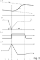
- Figure 3 shows the ways in which a shift to a lower gear is carried out, the driver sending the downshift command by acting upon the downshift paddle shifter 25 while the accelerator pedal 22 is released.
- Figure 3 shows, starting from the top:
- the control unit 12 of the drivetrain 6 As soon as the control unit 12 of the drivetrain 6 receives the gear shift command from the driver (instant to), the control unit 12 of the drivetrain immediately starts filling the incoming clutch 16B, namely it immediately starts feeding oil under pressure into the incoming clutch 16B; indeed, the incoming clutch 16B associated with the following gear B can transmit a significant torque to the rear drive wheels 3 only when the filling with oil under pressure has been completed and, hence, the oil under pressure, for it cannot occupy further volume inside the incoming clutch 16B, exerts a thrust that packs the discs of the incoming clutch 16B.
- the incoming clutch 16B associated with the following gear B can actually start transmitting a significant torque to the rear drive wheels 3, it is necessary to wait for a given delay time interval (typically ranging from 80 to 220 thousandths of second), during which the filling of the incoming clutch 16B with oil is completed.
- the completion of the filling of the incoming clutch 16B is normally monitored through a pressure sensor, which detects the pressure of the oil inside the incoming clutch 16B: when the pressure of the oil inside the incoming clutch 16B exceeds a predetermined threshold, this means that the inner volume of the incoming clutch 16B was completely filled and, hence, the oil inside the clutch 16B starts compressing.
- the incoming clutch 16B starts transmitting a torque T B (namely, the torque T B starts increasing) and, at the same time, the outgoing clutch 16A is ordered to open (namely, the torque T A starts decreasing); it should be pointed out that the opening of the outgoing clutch 16A associated with the current gear A takes place with no delay as the outgoing clutch 16A is already filled with oil under pressure and, in this phase, it simply needs to be emptied from part of the oil by opening a solenoid valve (whose action, thus, is instantaneous).
- the torque transmitted by the outgoing clutch 16A progressively decreases (the outgoing clutch 16A is opened by means of a linear ramp) and, at the same time, the torque transmitted by the incoming clutch 16B progressively increases (the incoming clutch 16B is closed by means of a linear ramp), thus determining a crossing between the two clutches 16A and 16B.
- the clutches 16A and 16B are opened and closed by means of linear ramps, namely the respective torques T A and T B change over time (decreasing and increasing) with linear variation laws.
- the outgoing clutch 16A is completely opened in the same amount of time needed to completely close the incoming clutch 16B, so as to obtain a symmetric crossing.
- the outgoing clutch 16A is completely open (hence, it does not transmit any torque any longer), whereas the incoming clutch 16B transmits the entire torque T E of the internal combustion engine 4.
- the rotation speed ⁇ E of the internal combustion engine 4 is equal to the rotation speed ⁇ A imposed by the gear ratio of the current gear A before the gear shift until the instant t 3 , it progressively increases towards the rotation speed ⁇ B imposed by the gear ratio of the following gear during the gear shift and is equal to the rotation speed ⁇ B after the gear shift.
- the rotation speed ⁇ E of the internal combustion engine 4 is equal (corresponds) to the rotation speed ⁇ A imposed by the gear ratio of the current gear A associated with the outgoing clutch 16A; as a consequence, the rotation speed ⁇ E of the internal combustion engine 4 is increased only after the outgoing clutch 16A has been completely opened.
- the internal combustion engine 4 In order to increase the rotation speed ⁇ E of the internal combustion engine 4 after the complete opening of the incoming clutch 16A, between the instants t 2 and t 4 the internal combustion engine 4 is turned on so as to have it generate a positive torque T E (namely, a drive torque and not a braking torque); i.e. the internal combustion engine 4 is turned on in the instant t 2 and is turned off in the instant t 4 .
- T E generated by the internal combustion engine 4 is temporarily increased (so that, between the instants t 2 and t 4 , it becomes a drive torque and is not a braking torque any longer).
- the longitudinal acceleration ⁇ of the road vehicle 1 is approximately constant and equal to the value ⁇ A (which is negative, since the vehicle is slowing down) immediately before the gear shift and is approximately constant and equal to the value ⁇ B (which is negative, since the vehicle is slowing down, and greater than the value ⁇ A in absolute value) immediately after the gear shift.
- the longitudinal acceleration of the vehicle 1 progressively decreases from the initial value ⁇ A to the final value ⁇ B .
- the advance of the complete opening of the outgoing clutch 16A relative to the complete transfer (which takes place in the instant t 3 ) of the entire torque T E of the internal combustion engine 4 to the incoming clutch 16B is zero, namely the outgoing clutch 16A is completely opened in the instant t 3 in which the transfer of the entire torque T E of the internal combustion engine 4 to the incoming clutch 16B is completed; said advance is identified in figure 3 with the term AMT indx and is zero (namely, minimal).
- the downshift takes place in the same ways shown in figure 3 and described above, with the sole difference that the advance AMT indx of the complete opening of the outgoing clutch 16A relative to the complete transfer of the entire torque T E of the internal combustion engine 4 to the incoming clutch 16B is no longer zero (on a scale from 0 to 100 it is approximately 40), namely the outgoing clutch 16A is completely opened before the complete transfer (which takes place in the instant t 3 ) of the entire torque T E of the internal combustion engine 4 to the incoming clutch 16B; in other words, the outgoing clutch 16A is completely opened in advance relative to the instant t 3 in which the transfer of the entire torque T E of the internal combustion engine 4 to the incoming clutch 16B is completed.
- the downshift takes place in the same ways shown in figure 3 and described above, with the sole difference that the advance AMT indx of the complete opening of the outgoing clutch 16A relative to the complete transfer of the entire torque T E of the internal combustion engine 4 to the incoming clutch 16B is no longer zero, but is maximum (on a scale from 0 to 100 it is 100), namely the outgoing clutch 16A is completely opened in the instant t 2 , long before the complete transfer (which takes place in the instant t 3 ) of the entire torque T E of the internal combustion engine 4 to the incoming clutch 16B; in other words, the outgoing clutch 16A is completely opened in the instant t 2 , significantly in advance relative to the instant t 3 in which the transfer of the entire torque T E of the internal combustion engine 4 to the incoming clutch 16B is completed.
- the advance AMT indx indicates the extent to which the complete opening of the outgoing clutch 16A is advanced relative to the complete transfer (which takes place in the instant t 3 ) of the entire torque T E of the internal combustion engine 4 to the incoming clutch 16B and ranges from a minimum of zero (the complete opening of the outgoing clutch 16A takes place in the same instant t 3 as the complete transfer of the entire torque T E of the internal combustion engine 4 to the incoming clutch 16B, like in the embodiment shown in figure 3 ) to a maximum of 100 (the complete opening of the outgoing clutch 16A takes place in the instant t 2 , like in the embodiment shown in figure 5 ).
- the control unit 12 of the drivetrain 6 can act upon the advance AMT indx so as to obtain different downshifts depending on the desires expressed by the driver (who could act upon a selector known as " hand lever " to choose the preferred driving style, namely a more comfort-oriented style or more fun/sports oriented style).
- the time profile of the longitudinal deceleration ⁇ of the road vehicle 1 changes.
- the internal combustion engine 4 is in cut-off condition before the downshift (hence, it operates as engine brake generating a braking torque T E ) and continues being in a cut-off condition even after the downshift; namely, before, during and after the downshift the driver keeps the accelerator pedal 22 completely released.
- control unit 12 of the drivetrain 6 must anyway complete the downshift that has already started, but can try and give an immediate response to the new (and unpredicted) request of the driver, so as to give the driver a feeling of extreme responsiveness; as a consequence, starting from the instant t 6 , the control unit 12 of the drivetrain 6 requests that the control unit 11 of the internal combustion engine 4 increases the torque T E generated by the internal combustion engine 4 (according to the request of the driver, who pressed the accelerator pedal 22) and, at the same time, accelerates the closing of the incoming clutch 16B (namely, makes the closing of the incoming clutch 16B faster), which, obviously, now has to transmit, as a whole, a greater torque T B due to the fact that the internal combustion engine 4 was turned on.
- control method described above has different advantages.
- the method to control the execution of a shift to a lower gear with a released accelerator pedal described above is very comfortable, as, since the transmission of the torque to the drive wheels 3 is never interrupted, it determines a comfortable longitudinal acceleration profile of the road vehicle: indeed, the longitudinal acceleration of the road vehicle gradually shifts, without gradient inversion, from an initial deceleration to a final deceleration, which is greater than the previous one (in the downshift the gear ratio gets shorter and, therefore, the engine brake has a more incisive effect on the dynamic of the road vehicle 1); in this way, the driver always has a feeling of continuous deceleration.
- the method to control the execution of a shift to a lower gear with a released accelerator pedal described above does not generate any perceivable metal noise, as the two clutches 16A and 16B never are both open at the same time and, hence, the drivetrain 6 always is " under stress "; namely, backlashes are significantly reduced and, as a consequence, so are noises, since the gear trains of the drivetrain 6 always are " under stress " .
- the method to control the execution of a shift to a lower gear with a released accelerator pedal described above also allows for the implementation of a new strategy (also called “ change of mind "), which allows the torque T B of the incoming clutch 16B to be adjusted if, during the downshift, the driver presses the accelerator pedal 22, thus allowing for a more prompt and quick response of the road vehicle 1 to the commands of the driver.
- a new strategy also called “ change of mind "
- the method to control the execution of a shift to a lower gear with a released accelerator pedal described above allows for a customization of the time profile of the longitudinal acceleration ⁇ of the road vehicle 1 based on the preferences of the driver, with a simple adjustment of the advance AMT indx of the complete opening of the outgoing clutch 16A relative to the complete transfer of the entire torque T E of the internal combustion engine 4 to the incoming clutch 16B.
- control method described above is easy and economic to be implemented, since it does not require the installation of additional physical components and does not call for an expansion of the control unit 12 of the drivetrain 6, since no additional calculation ability is needed.
Description
- The invention relates to a method to control the execution of a downshift with a released accelerator pedal in a drivetrain provided with a dual-clutch, servo-assisted transmission (namely, a gear shift in which the following or incoming gear is lower than the previous or outgoing gear).
- A drivetrain provided with a dual-clutch, servo-assisted transmission comprises a pair of primary shafts, which are coaxial to one another, are independent of one another and are inserted inside one another; two coaxial clutches, each designed to connect a respective primary shaft to a drive shaft of an internal combustion engine; and at least one secondary shaft, which transmits the motion to the drive wheels and can be coupled to the primary shafts by means of respective gear trains, each defining a gear.
- During a gear shift, the current gear couples the secondary shaft to a primary shaft, while the following gear couples the secondary shaft to the other primary shaft; as a consequence, the gear shift takes place by crossing the two clutches, namely by opening the clutch associated with the current gear and by simultaneously closing the clutch associated with the following gear.
- Currently, a downshift with a released accelerator pedal entails opening the outgoing clutch (namely, the clutch associated with the previous gear), increasing the rotation speed of the internal combustion engine by turning on the internal combustion engine (namely, by having the internal combustion engine generate a positive torque determining an acceleration of the drive shaft) and, finally, closing the incoming clutch (namely, the clutch associated with the following gear). In this way, the synchronization (increase) of the rotation speed of the internal combustion engine with the speed imposed by the following gear (namely, by the incoming clutch) takes place when both clutches are open, thus causing the internal combustion engine to generate a positive torque (whereas, for the remaining time, the internal combustion engine is in cut-off condition and operates as engine brake, generating a resisting, namely braking torque).
- This mode of execution a downshift with a released accelerator pedal is "fun" (namely, appreciated by drivers, since it provides a feeling of sports-driving also thanks to the sound produced by the internal combustion engine during the synchronization of its own rotation speed), but, on the other hand, it is not very comfortable, since, because of the interruption in the transmission of the torque to the drive wheels, it determines an uncomfortable longitudinal acceleration profile of the road vehicle: indeed, the longitudinal acceleration of the road vehicle suddenly shifts from an initial deceleration to a zero acceleration in order to then quickly go back to a final deceleration, which is greater than the previous one (the feeling resulting from this is a quick backward pull and a subsequent forward pull, which, as a whole, are not very comfortable).
- Furthermore, this gear shift execution mode generates a certain metal noise (which can generally be perceived by drivers, especially at a low rpm), since the simultaneous opening of the two clutches determines an unloading of the drivetrain with a subsequent restoring of backlashes when the incoming clutch is closed.
- Patent application
EP3139070A1 describes a method to control the execution of a downshift while an accelerator pedal is released in a drivetrain provided with a dual-clutch, servo-assisted transmission. The method comprises the following steps: in a first instant, opening an outgoing clutch associated with the current gear and closing an incoming clutch associated with the following gear; in a second instant, completing the opening of the outgoing clutch and completing the closing of the incoming clutch; synchronizing, between the second instant and a third instant, a rotation speed of the internal combustion engine with a rotation speed of the incoming clutch, namely with the rotation speed imposed by the gear ratio of the following gear; and controlling the incoming clutch between the second instant and the third instant so as to have the incoming clutch temporarily transmit a greater torque than the braking torque of the internal combustion engine in order to accelerate the internal combustion engine using the kinetic energy owned by the road vehicle. - The object of the invention is to provide a method to control the execution of a downshift with a released accelerator pedal in a drivetrain provided with a dual-clutch, servo-assisted transmission, said method not suffering from the drawbacks discussed above and, at the same time, being easy and economic to be implemented.
- According to the invention there is provided a method to control the execution of a downshift with a released accelerator pedal in a drivetrain provided with a dual-clutch, servo-assisted transmission, according to the appended claims.
- The invention will now be described with reference to the accompanying drawings, showing a non-limiting embodiment thereof, wherein:
-
figure 1 is a schematic plan view of a rear-wheel drive road vehicle provided with a drivetrain with a dual-clutch, servo-assisted transmission, which is controlled according to the control method of the invention; -
figure 2 is a schematic view of the drivetrain offigure 1 ; and -
figures 3-6 show the time development of the torques transmitted by the two clutches of the dual-clutch transmission, of the rotation speed of a drive shaft of the internal combustion engine, of the longitudinal deceleration of the road vehicle and of the torque generated by the internal combustion engine during respective downshifts carried out with the control method according to the invention. - In
figure 1 ,number 1 indicates, as a whole, a road vehicle (in particular, a car) provided with two front driven (namely, non-drive)wheels 2 and with tworear drive wheels 3. In a front position there is aninternal combustion engine 4, which is provided with adrive shaft 5, which produces a torque TE, which is transmitted to thedrive wheels 3 by means of adrivetrain 6. Thedrivetrain 6 comprises a dual-clutch, servo-assistedtransmission 7 arranged in the rear-wheel-drive assembly and atransmission shaft 8, which connects thedrive shaft 5 to an input of the dual-clutch, servo-assistedtransmission 7. The dual-clutch, servo-assistedtransmission 7 is connected, in a train-like manner, to a self-lockingdifferential 9, from which a pair ofaxle shafts 10 start, each integral to adrive wheel 3. - The
road vehicle 1 comprises acontrol unit 11 of theinternal combustion engine 4, which controls theinternal combustion engine 4, acontrol unit 12 of thedrivetrain 6, which controls thedrivetrain 6, and aBUS line 13, which is manufactured, for example, according to the CAN (Car Area Network) protocol, extends to theentire road vehicle 1 and allows the twocontrol units control unit 11 of theinternal combustion engine 4 and thecontrol unit 12 of thedrivetrain 6 are connected to theBUS line 13 and, therefore, can communicate with one another by means of messages sent through theBUS line 13. Furthermore, thecontrol unit 11 of theinternal combustion engine 4 and thecontrol unit 12 of thedrivetrain 6 can be directly connected to one another by means of a dedicated synchronization cable 14, which is capable of directly transmitting a signal from thecontrol unit 12 of thedrivetrain 6 to thecontrol unit 11 of theinternal combustion engine 4 without the delays caused by theBUS line 13. Alternatively, the synchronization cable 14 could be absent and all communications between the twocontrol units BUS line 13. - According to
figure 2 , the dual-clutch, servo-assistedtransmission 7 comprises a pair ofprimary shafts 15, which are coaxial to one another, independent of one another and inserted inside one another. Furthermore, the dual-clutch, servo-assistedtransmission 7 comprises two coaxial clutches 16, each designed to connect a respectiveprimary shaft 15 to thedrive shaft 5 of theinternal combustion engine 4 through the interposition of thetransmission shaft 8; each clutch 16 is an oil bath clutch and, hence, is pressure-controlled (i.e. the degree of opening/closing of the clutch 16 is determined by the pressure of the oil inside the clutch 16); according to an alternative embodiment, each clutch 16 is a dry clutch and, hence, is position-controlled (i.e. the degree of opening/closing of the clutch 16 is determined by the position of a movable element of the clutch 16). The dual-clutch, servo-assistedtransmission 7 comprises one singlesecondary shaft 17 connected to thedifferential 9 that transmits the motion to thedrive wheels 3; according to an alternative and equivalent embodiment, the dual-clutch, servo-assistedtransmission 7 comprises twosecondary shafts 17, both connected to thedifferential 9. - The dual-clutch, servo-assisted
transmission 7 has seven forward gears indicated with Roman numerals (first gear I, second gear II, third gear III, fourth gear IV, fifth gear V, sixth gear VI and seventh gear VII) and a reverse gear (indicated with R). Theprimary shaft 15 and thesecondary shaft 17 are mechanically coupled to one another by a plurality of gear trains, each defining a respective gear and comprising aprimary gear wheel 18 fitted on theprimary shaft 15 and asecondary gear wheel 19 fitted on thesecondary shaft 17. In order to allow for a correct operation of the dual-clutch, servo-assistedtransmission 7, all odd gears (first gear I, third gear III, fifth gear V, seventh gear VII) are coupled to a sameprimary shaft 15, whereas all even gears (second gear II, fourth gear IV and sixth gear VI) are coupled to the otherprimary shaft 15. - Each
primary gear wheel 18 is splined to a respectiveprimary shaft 15, so as to always rotate with theprimary shaft 15 in an integral manner, and permanently meshes with the respectivesecondary gear wheel 19; on the other hand, eachsecondary gear wheel 19 is mounted on thesecondary shaft 17 in an idle manner. Furthermore, the dual-clutch, servo-assistedtransmission 7 comprises foursynchronizers 20, each mounted coaxial to thesecondary shaft 17, arranged between twosecondary gear wheels 19 and designed to be operated so as to alternatively fit the two respectivesecondary gear wheels 19 to the secondary shaft 17 (i.e. so as to alternatively cause the two respectivesecondary gear wheels 19 to become angularly integral to the secondary shaft 17). In other words, eachsynchronizer 20 can be moved in one direction to fit asecondary gear wheel 19 to thesecondary shaft 17 or can be moved in the other direction to fit the othersecondary gear wheel 19 to thesecondary shaft 17. - The dual-
clutch transmission 7 comprises one singlesecondary shaft 17 connected to thedifferential 9 that transmits the motion to thedrive wheels 3; according to an alternative and equivalent embodiment, the dual-clutch transmission 7 comprises twosecondary shafts 17, both connected to thedifferential 9. - According to
figure 1 , theroad vehicle 1 comprises a passenger compartment housing a driving position for the driver; the driving position comprises a seat (which is not shown), asteering wheel 21, anaccelerator pedal 22, abrake pedal 23 and twopaddle shifters transmission 7 and are connected to the opposite sides of thesteering wheel 21. Theupshift paddle shifter 24 is operated by the driver (by means of a short pressure) in order to request an upshift (namely, the engagement of a new gear, which is higher than the current gear and contiguous with the current gear), whereas thedownshift paddle shifter 25 is operated by the driver (by means of short pressure) in order to request a downshift (namely, the engagement of a new gear, which is lower than the current gear and is contiguous with the current gear). - Hereinafter there is a description of the modes of execution of a downshift with a released
accelerator pedal 22 from a current, higher gear A to a following, lower gear B (when theaccelerator pedal 22 is released, theinternal combustion engine 4 operates in cut-off condition and acts as engine brake); namely, the current gear A has a greater gear ratio than the following gear B (hence, given the same speed of theroad vehicle 1, the current gear A causes theinternal combustion engine 4 to run more slowly than the following gear B). - In an initial situation (i.e. before the gear shift), an
outgoing clutch 16B is closed in order to transmit the motion to a primary shaft 15A, which, in turn, transmits the motion to thesecondary shaft 17 through the current gear A, which is engaged; anincoming clutch 16B, on the other hand, is open and, hence isolates aprimary shaft 15B from thetransmission shaft 8. Before beginning the upshift, the following gear B is engaged in order to connect, through the gear B, theprimary shaft 15B to thesecondary shaft 17. When the driver sends the gear shift command, the gear shift is carried out by opening theoutgoing clutch 16A in order to disconnect the primary shaft 15A (hence, the gear A) from the transmission shaft 8 (i.e. from thedrive shaft 5 of the internal combustion engine 4) and, (more or less) simultaneously, by closing theincoming clutch 16B in order to connect theprimary shaft 15B (hence, the gear B) to the transmission shaft 8 (i.e. to thedrive shaft 5 of the internal combustion engine 4). -
Figure 3 shows the ways in which a shift to a lower gear is carried out, the driver sending the downshift command by acting upon thedownshift paddle shifter 25 while theaccelerator pedal 22 is released.Figure 3 shows, starting from the top: - a first diagram showing the time development of the rotation speed ωE of the
internal combustion engine 4, the rotation speed ωA of theoutgoing clutch 16A and the rotation speed ωB of theincoming clutch 16B; - a second diagram showing the time development of the torques TA and TB transmitted by the two
clutches - a third diagram showing the time development of the torque TE generated by the internal combustion engine 4 (before and after the downshift the
internal combustion engine 4 is in cut-off condition and, hence, operates in engine braking mode generating a negative torque TE); and - a fourth diagram showing the time development of the longitudinal acceleration α of the vehicle 1 (it should be pointed out that the longitudinal acceleration α of the
vehicle 1 always is negative, namely thevehicle 1 is slowing down as theinternal combustion engine 4 is substantially generating a negative torque TE, namely is braking, thus operating in engine braking mode). - As soon as the
control unit 12 of thedrivetrain 6 receives the gear shift command from the driver (instant to), thecontrol unit 12 of the drivetrain immediately starts filling theincoming clutch 16B, namely it immediately starts feeding oil under pressure into theincoming clutch 16B; indeed, theincoming clutch 16B associated with the following gear B can transmit a significant torque to therear drive wheels 3 only when the filling with oil under pressure has been completed and, hence, the oil under pressure, for it cannot occupy further volume inside theincoming clutch 16B, exerts a thrust that packs the discs of theincoming clutch 16B. As a consequence, before theincoming clutch 16B associated with the following gear B can actually start transmitting a significant torque to therear drive wheels 3, it is necessary to wait for a given delay time interval (typically ranging from 80 to 220 thousandths of second), during which the filling of theincoming clutch 16B with oil is completed. The completion of the filling of theincoming clutch 16B is normally monitored through a pressure sensor, which detects the pressure of the oil inside theincoming clutch 16B: when the pressure of the oil inside theincoming clutch 16B exceeds a predetermined threshold, this means that the inner volume of theincoming clutch 16B was completely filled and, hence, the oil inside theclutch 16B starts compressing. As a consequence, the instant t1 in which (after the delay time has elapsed) theincoming clutch 16B is filled with oil and is ready to transit a significant torque is established when the pressure of the oil inside theincoming clutch 16B exceeds the predetermined threshold. - From the instant t0, in which the
control unit 12 of the drivetrain immediately starts closing theincoming clutch 16B, to the instant t1, in which, after the delay time has elapsed, theincoming clutch 16B is filled with oil and is ready to transmit a significant torque, nothing happens to the dynamic of theroad vehicle 1, i.e. the entire torque TE generated by the internal combustion engine 4 (which is a negative torque TE, namely a braking torque TE, since theinternal combustion engine 4 is in cut-off condition and, hence, operates as engine brake) is entirely transmitted by theoutgoing clutch 16A, like before the beginning of the gear shift. In the instant t1, theincoming clutch 16B starts transmitting a torque TB (namely, the torque TB starts increasing) and, at the same time, theoutgoing clutch 16A is ordered to open (namely, the torque TA starts decreasing); it should be pointed out that the opening of theoutgoing clutch 16A associated with the current gear A takes place with no delay as theoutgoing clutch 16A is already filled with oil under pressure and, in this phase, it simply needs to be emptied from part of the oil by opening a solenoid valve (whose action, thus, is instantaneous). - Between the instants t1 and t2 there is a partial and reduced transfer of torque between the two
clutches outgoing clutch 16A decreases in a step-like manner and, at the time, the torque transmitted by theincoming clutch 16B increases in a step-like manner and by the same quantity. Subsequently, between the instants t2 and t3 there is the complete transfer of torque between the twoclutches outgoing clutch 16A progressively decreases (theoutgoing clutch 16A is opened by means of a linear ramp) and, at the same time, the torque transmitted by theincoming clutch 16B progressively increases (theincoming clutch 16B is closed by means of a linear ramp), thus determining a crossing between the twoclutches clutches - In the embodiment shown in
figure 3 , theoutgoing clutch 16A is completely opened in the same amount of time needed to completely close theincoming clutch 16B, so as to obtain a symmetric crossing. In the instant t3, theoutgoing clutch 16A is completely open (hence, it does not transmit any torque any longer), whereas theincoming clutch 16B transmits the entire torque TE of theinternal combustion engine 4. Between the instants t1 and t3 there is the shifting time, during which the torque transmitted by theoutgoing clutch 16A decreases until it becomes zero and, simultaneously, the torque transmitted by theincoming clutch 16B increases until it reaches the torque TE generated by the internal combustion engine 4 (as already mentioned above, theinternal combustion engine 4 is in cut-off condition and, hence, operates as engine brake, thus generating a negative torque TE), namely during which theoutgoing clutch 16A separates itself from thedrive wheels 3 and theincoming clutch 16B gets connected to thedrive wheels 3. - The rotation speed ωE of the
internal combustion engine 4 is equal to the rotation speed ωA imposed by the gear ratio of the current gear A before the gear shift until the instant t3, it progressively increases towards the rotation speed ωB imposed by the gear ratio of the following gear during the gear shift and is equal to the rotation speed ωB after the gear shift. According tofigure 3 , until the instant t3 theclutch 16A is not completely open yet and, therefore, the rotation speed ωE of theinternal combustion engine 4 is equal (corresponds) to the rotation speed ωA imposed by the gear ratio of the current gear A associated with theoutgoing clutch 16A; as a consequence, the rotation speed ωE of theinternal combustion engine 4 is increased only after theoutgoing clutch 16A has been completely opened. - Between the instants t3 and t4 there is the synchronization time, during which the rotation speed ωE of the
internal combustion engine 4 increases from the rotation speed ωA imposed by the gear ratio of the current gear A to the rotation speed ωB imposed by the gear ratio of the following gear B, namely the rotation speed ωE is synchronized with the rotation speed ωB. - In order to increase the rotation speed ωE of the
internal combustion engine 4 after the complete opening of the incoming clutch 16A, between the instants t2 and t4 theinternal combustion engine 4 is turned on so as to have it generate a positive torque TE (namely, a drive torque and not a braking torque); i.e. theinternal combustion engine 4 is turned on in the instant t2 and is turned off in the instant t4. In other words, in order to synchronize the rotation speed ωE of theinternal combustion engine 4 with the rotation speed ωB of the incoming clutch 16B, the torque TE generated by theinternal combustion engine 4 is temporarily increased (so that, between the instants t2 and t4, it becomes a drive torque and is not a braking torque any longer). - The longitudinal acceleration α of the
road vehicle 1 is approximately constant and equal to the value αA (which is negative, since the vehicle is slowing down) immediately before the gear shift and is approximately constant and equal to the value αB (which is negative, since the vehicle is slowing down, and greater than the value αA in absolute value) immediately after the gear shift. During the gear shift, the longitudinal acceleration of thevehicle 1 progressively decreases from the initial value αA to the final value αB. - In the embodiment shown in
figure 3 , the advance of the complete opening of the outgoing clutch 16A relative to the complete transfer (which takes place in the instant t3) of the entire torque TE of theinternal combustion engine 4 to the incoming clutch 16B is zero, namely the outgoing clutch 16A is completely opened in the instant t3 in which the transfer of the entire torque TE of theinternal combustion engine 4 to the incoming clutch 16B is completed; said advance is identified infigure 3 with the term AMTindx and is zero (namely, minimal). In the variant shown infigure 4 , the downshift takes place in the same ways shown infigure 3 and described above, with the sole difference that the advance AMTindx of the complete opening of the outgoing clutch 16A relative to the complete transfer of the entire torque TE of theinternal combustion engine 4 to the incoming clutch 16B is no longer zero (on a scale from 0 to 100 it is approximately 40), namely the outgoing clutch 16A is completely opened before the complete transfer (which takes place in the instant t3) of the entire torque TE of theinternal combustion engine 4 to the incoming clutch 16B; in other words, the outgoing clutch 16A is completely opened in advance relative to the instant t3 in which the transfer of the entire torque TE of theinternal combustion engine 4 to the incoming clutch 16B is completed. In the further variant shown infigure 5 , the downshift takes place in the same ways shown infigure 3 and described above, with the sole difference that the advance AMTindx of the complete opening of the outgoing clutch 16A relative to the complete transfer of the entire torque TE of theinternal combustion engine 4 to the incoming clutch 16B is no longer zero, but is maximum (on a scale from 0 to 100 it is 100), namely the outgoing clutch 16A is completely opened in the instant t2, long before the complete transfer (which takes place in the instant t3) of the entire torque TE of theinternal combustion engine 4 to the incoming clutch 16B; in other words, the outgoing clutch 16A is completely opened in the instant t2, significantly in advance relative to the instant t3 in which the transfer of the entire torque TE of theinternal combustion engine 4 to the incoming clutch 16B is completed. - In other words, the advance AMTindx indicates the extent to which the complete opening of the outgoing clutch 16A is advanced relative to the complete transfer (which takes place in the instant t3) of the entire torque TE of the
internal combustion engine 4 to theincoming clutch 16B and ranges from a minimum of zero (the complete opening of the outgoing clutch 16A takes place in the same instant t3 as the complete transfer of the entire torque TE of theinternal combustion engine 4 to the incoming clutch 16B, like in the embodiment shown infigure 3 ) to a maximum of 100 (the complete opening of the outgoing clutch 16A takes place in the instant t2, like in the embodiment shown infigure 5 ). - By changing the advance AMTindx, the mode of execution of the downshift is changed as well; as a consequence, the
control unit 12 of thedrivetrain 6 can act upon the advance AMTindx so as to obtain different downshifts depending on the desires expressed by the driver (who could act upon a selector known as "hand lever" to choose the preferred driving style, namely a more comfort-oriented style or more fun/sports oriented style). Indeed, it should be pointed out that, in the embodiments shown infigures 3 ,4 and5 , the time profile of the longitudinal deceleration α of theroad vehicle 1 changes. - In the embodiments shown in
figures 3 ,4 and5 , theinternal combustion engine 4 is in cut-off condition before the downshift (hence, it operates as engine brake generating a braking torque TE) and continues being in a cut-off condition even after the downshift; namely, before, during and after the downshift the driver keeps theaccelerator pedal 22 completely released. However, it can happen that the driver, after having requested the downshift (namely, after the instant to), decides to press theaccelerator pedal 22, thus requesting that theinternal combustion engine 4 generates a positive torque TE (namely, a drive torque); this situation is present in the embodiment shown infigure 6 , in which in the instant t6 (for example placed between the instant t2 and the instant t3) the driver, after having requested the downshift (namely, after the instant to), presses theaccelerator pedal 22. Obviously, thecontrol unit 12 of thedrivetrain 6 must anyway complete the downshift that has already started, but can try and give an immediate response to the new (and unpredicted) request of the driver, so as to give the driver a feeling of extreme responsiveness; as a consequence, starting from the instant t6, thecontrol unit 12 of thedrivetrain 6 requests that thecontrol unit 11 of theinternal combustion engine 4 increases the torque TE generated by the internal combustion engine 4 (according to the request of the driver, who pressed the accelerator pedal 22) and, at the same time, accelerates the closing of the incoming clutch 16B (namely, makes the closing of theincoming clutch 16B faster), which, obviously, now has to transmit, as a whole, a greater torque TB due to the fact that theinternal combustion engine 4 was turned on. - The control method described above has different advantages.
- First of all, the method to control the execution of a shift to a lower gear with a released accelerator pedal described above is very comfortable, as, since the transmission of the torque to the
drive wheels 3 is never interrupted, it determines a comfortable longitudinal acceleration profile of the road vehicle: indeed, the longitudinal acceleration of the road vehicle gradually shifts, without gradient inversion, from an initial deceleration to a final deceleration, which is greater than the previous one (in the downshift the gear ratio gets shorter and, therefore, the engine brake has a more incisive effect on the dynamic of the road vehicle 1); in this way, the driver always has a feeling of continuous deceleration. - Furthermore, the method to control the execution of a shift to a lower gear with a released accelerator pedal described above does not generate any perceivable metal noise, as the two
clutches drivetrain 6 always is "under stress"; namely, backlashes are significantly reduced and, as a consequence, so are noises, since the gear trains of thedrivetrain 6 always are "under stress". - The method to control the execution of a shift to a lower gear with a released accelerator pedal described above also allows for the implementation of a new strategy (also called "change of mind"), which allows the torque TB of the incoming clutch 16B to be adjusted if, during the downshift, the driver presses the
accelerator pedal 22, thus allowing for a more prompt and quick response of theroad vehicle 1 to the commands of the driver. - The method to control the execution of a shift to a lower gear with a released accelerator pedal described above allows for a customization of the time profile of the longitudinal acceleration α of the
road vehicle 1 based on the preferences of the driver, with a simple adjustment of the advance AMTindx of the complete opening of the outgoing clutch 16A relative to the complete transfer of the entire torque TE of theinternal combustion engine 4 to the incoming clutch 16B. - Finally, the control method described above is easy and economic to be implemented, since it does not require the installation of additional physical components and does not call for an expansion of the
control unit 12 of thedrivetrain 6, since no additional calculation ability is needed. -
- 1
- road vehicle
- 2
- front wheels
- 3
- rear wheels
- 4
- engine
- 5
- drive shaft
- 6
- drivetrain
- 7
- transmission
- 8
- transmission shaft
- 9
- differential
- 10
- axle shafts
- 11
- engine control unit
- 12
- drivetrain control unit
- 13
- BUS line
- 14
- synchronization cable
- 15
- primary shafts
- 16
- clutches
- 17
- secondary shaft
- 18
- primary gear wheel
- 19
- secondary gear wheel
- 20
- synchronizers
- 21
- steering wheel
- 22
- accelerator pedal
- 23
- brake pedal
- 24
- upshift paddle shifter
- 25
- downshift paddle shifter
- ωE
- rotation speed
- ωA
- rotation speed
- ωB
- rotation speed
- TE
- torque
- TA
- torque
- TB
- torque
- α
- acceleration
- to
- time instant
- t1
- time instant
- t2
- time instant
- t3
- time instant
- t4
- time instant
- t5
- time instant
- t6
- time instant
- AMTindx
- advance of the complete opening
Claims (11)
- A method to control the execution of a downshift with a released accelerator pedal (22) in a drivetrain (6) provided with a dual-clutch, servo-assisted transmission (7), so as to shift from a current gear (A) to a following gear (B), which has a shorter transmission ratio than the current gear (A); wherein the drivetrain (6) belongs to a road vehicle (1) driven by a driver and provided also with an internal combustion engine (4) and with the accelerator pedal (22) ;the drivetrain (6) comprises a dual-clutch, servo-assisted transmission (7) having two primary shafts (15); at least one secondary shaft (17) connected to drive wheels (3); and two clutches (16A, 16B), each interposed between a drive shaft (5) of the internal combustion engine (4) and a corresponding primary shaft (15);the control method comprises the steps of:opening, in a first instant (t1), an outgoing clutch (16A) associated with the current gear (A);closing, in the first instant (t1), an incoming clutch (16B) associated with the following gear (B);completing the opening of the outgoing clutch (16A) by means of a first linear ramp in a second instant;closing the incoming clutch (16B) by means of a second linear ramp starting from a third instant (t2), which is prior to or coincides with the second instant;synchronizing, between the second instant and a fourth instant (t4), a rotation speed (ωE) of the internal combustion engine (4) with a rotation speed (ωB) of the incoming clutch (16B), namely with the rotation speed (ωB) imposed by the gear ratio of the following gear (B); andcompleting the closing of the incoming clutch (16B) in a fifth instant (t3), which coincides with or is subsequent to the second instant;the control method is characterized in that it comprises the further step of activating the internal combustion engine (4) so as to generate a torque (TE) between the third instant (t2) and the fourth instant (t4) in order to increase the rotation speed (ωE) of the internal combustion engine (4).
- The control method according to claim 1, wherein the fifth instant (t3) coincides with the second instant.
- The control method according to claim 1, wherein the fifth instant (t3) is subsequent to the second instant.
- The control method according to claim 1, 2 or 3, wherein the third instant (t2) is prior to the second instant.
- The control method according to claim 1, 2 or 3, wherein the third instant (t2) coincides with the second instant.
- The control method according to one of the claims from 1 to 5, wherein a longitudinal deceleration (α) of the road vehicle (1) increases between the fourth instant (t2) and the fifth instant (t3).
- The control method according to one of the claims from 1 to 6 and comprising the further steps of:detecting a preference of the driver; andchanging, based on the preference of the driver, an advance (AMTindx) of the complete opening of the outgoing clutch (16A) relative to a complete transfer of the entire torque (TE) of the internal combustion engine (4) to the incoming clutch (16B).
- The control method according to claim 7, wherein the advance (AMTindx) of the complete opening of the outgoing clutch (16A) relative to the complete transfer of the entire torque (TE) of the internal combustion engine (4) to the incoming clutch (16B) is variable between a minimum, when the outgoing clutch (16A) is completely opened in the fifth instant (t3), and a maximum, when the outgoing clutch (16A) is completely opened in the fourth instant (t2).
- The control method according to one of the claims from 1 to 8, wherein the internal combustion engine (4) is in cut-off condition before the downshift and is in cut-off condition also after the downshift.
- The control method according to claim 9, wherein, before, during and after the downshift, the driver keeps the accelerator pedal (22) completely released.
- The control method according to one of the claims from 1 to 9 and comprising the further steps of:detecting a pressing of the accelerator pedal (22) exerted by the driver during the downshift;increasing, in case the accelerator pedal (22) is pressed by the driver during a downshift, the torque (TE) generated by the internal combustion engine (4); andaccelerating, in case the accelerator pedal (22) is pressed by the driver during a downshift, the closing of the incoming clutch (16B).
Applications Claiming Priority (1)
| Application Number | Priority Date | Filing Date | Title |
|---|---|---|---|
| IT102019000017528A IT201900017528A1 (en) | 2019-09-30 | 2019-09-30 | METHOD OF CONTROL FOR PERFORMING A DOWN SHIFT WITH THROTTLE PEDAL RELEASED IN A TRANSMISSION FITTED WITH A DOUBLE CLUTCH POWER ASSISTED TRANSMISSION |
Publications (2)
| Publication Number | Publication Date |
|---|---|
| EP3798478A1 EP3798478A1 (en) | 2021-03-31 |
| EP3798478B1 true EP3798478B1 (en) | 2022-07-13 |
Family
ID=69743639
Family Applications (1)
| Application Number | Title | Priority Date | Filing Date |
|---|---|---|---|
| EP20199328.4A Active EP3798478B1 (en) | 2019-09-30 | 2020-09-30 | Method to control the execution of a downshift with a released accelerator pedal in a drivetrain provided with a dual-clutch, servo-assisted transmission |
Country Status (5)
| Country | Link |
|---|---|
| US (1) | US11214260B2 (en) |
| EP (1) | EP3798478B1 (en) |
| JP (1) | JP2021055843A (en) |
| CN (1) | CN112572446A (en) |
| IT (1) | IT201900017528A1 (en) |
Families Citing this family (1)
| Publication number | Priority date | Publication date | Assignee | Title |
|---|---|---|---|---|
| US11767015B2 (en) * | 2020-12-16 | 2023-09-26 | Guangzhou Automobile Group Co., Ltd. | System, vehicle, method and non-transitory computer readable storage medium for improving driving safety |
Family Cites Families (6)
| Publication number | Priority date | Publication date | Assignee | Title |
|---|---|---|---|---|
| DE4204401A1 (en) * | 1992-02-14 | 1993-08-19 | Bosch Gmbh Robert | DEVICE FOR CONTROLLING THE OUTPUT TORQUE OF AN AUTOMATIC MANUAL TRANSMISSION |
| JP3988428B2 (en) * | 2001-10-09 | 2007-10-10 | 株式会社日立製作所 | Automatic transmissions, control devices, and automobiles |
| US8328688B2 (en) * | 2010-01-25 | 2012-12-11 | Ford Global Technologies, Llc | Ratio shift control system and method for a multiple-ratio automatic transmission |
| WO2014045357A1 (en) * | 2012-09-19 | 2014-03-27 | ヤマハ発動機株式会社 | Vehicle control device, vehicle, and engine |
| US10167952B2 (en) * | 2014-04-29 | 2019-01-01 | Hyundai Motor Company | Clutch torque control method for DCT vehicle |
| ITUB20153377A1 (en) * | 2015-09-03 | 2017-03-03 | Ferrari Spa | CONTROL METHOD FOR THE EXECUTION OF A GEAR CHANGE IN A TRANSMISSION PROVIDED WITH A DOUBLE CLUTCH CHANGE |
-
2019
- 2019-09-30 IT IT102019000017528A patent/IT201900017528A1/en unknown
-
2020
- 2020-09-21 US US17/026,691 patent/US11214260B2/en active Active
- 2020-09-23 JP JP2020158638A patent/JP2021055843A/en active Pending
- 2020-09-27 CN CN202011029957.0A patent/CN112572446A/en active Pending
- 2020-09-30 EP EP20199328.4A patent/EP3798478B1/en active Active
Also Published As
| Publication number | Publication date |
|---|---|
| EP3798478A1 (en) | 2021-03-31 |
| IT201900017528A1 (en) | 2021-03-30 |
| US11214260B2 (en) | 2022-01-04 |
| CN112572446A (en) | 2021-03-30 |
| US20210094549A1 (en) | 2021-04-01 |
| JP2021055843A (en) | 2021-04-08 |
Similar Documents
| Publication | Publication Date | Title |
|---|---|---|
| US10046769B2 (en) | Control method for carrying out a gear shift in a transmission provided with a dual-clutch gearbox | |
| US8257225B2 (en) | Control method for carrying out a gear upshifting in an automatic manual transmission having a dual-clutch gearbox | |
| EP3798478B1 (en) | Method to control the execution of a downshift with a released accelerator pedal in a drivetrain provided with a dual-clutch, servo-assisted transmission | |
| EP3798479B1 (en) | Method to control the execution of an upshift with a released accelerator pedal in a drivetrain provided with a dual-clutch, servo-assisted transmission | |
| US5624348A (en) | Process for determining the shifting time for a transmission ratio change in an infinitely variable transmission | |
| EP3798477B1 (en) | Method to control the execution of a downshift while an accelerator pedal is released in a drivetrain provided with a dual-clutch, servo-assisted transmission | |
| EP1436162B1 (en) | Control apparatus and method for shifting gears | |
| US9896110B2 (en) | Control method for carrying out a gear shift in a transmission provided with a dual-clutch gearbox | |
| EP3798476B1 (en) | Method to control a road vehicle for the execution of a multiple downshift in a drivetrain provided with a servo-assisted transmission | |
| EP3798472B1 (en) | Method to automatically control a drivetrain provided with a servo-assisted transmission | |
| EP3798473B1 (en) | Method to control a road vehicle provided with a servo-assisted transmission during a slowing-down phase | |
| JP3633142B2 (en) | Shift control device for automatic transmission |
Legal Events
| Date | Code | Title | Description |
|---|---|---|---|
| PUAI | Public reference made under article 153(3) epc to a published international application that has entered the european phase |
Free format text: ORIGINAL CODE: 0009012 |
|
| STAA | Information on the status of an ep patent application or granted ep patent |
Free format text: STATUS: THE APPLICATION HAS BEEN PUBLISHED |
|
| AK | Designated contracting states |
Kind code of ref document: A1 Designated state(s): AL AT BE BG CH CY CZ DE DK EE ES FI FR GB GR HR HU IE IS IT LI LT LU LV MC MK MT NL NO PL PT RO RS SE SI SK SM TR |
|
| AX | Request for extension of the european patent |
Extension state: BA ME |
|
| STAA | Information on the status of an ep patent application or granted ep patent |
Free format text: STATUS: REQUEST FOR EXAMINATION WAS MADE |
|
| 17P | Request for examination filed |
Effective date: 20210929 |
|
| GRAP | Despatch of communication of intention to grant a patent |
Free format text: ORIGINAL CODE: EPIDOSNIGR1 |
|
| STAA | Information on the status of an ep patent application or granted ep patent |
Free format text: STATUS: GRANT OF PATENT IS INTENDED |
|
| RIC1 | Information provided on ipc code assigned before grant |
Ipc: F16H 61/00 20060101ALN20220106BHEP Ipc: F16H 59/02 20060101ALN20220106BHEP Ipc: F16H 59/18 20060101ALN20220106BHEP Ipc: F16H 63/50 20060101ALI20220106BHEP Ipc: F16H 61/688 20060101ALI20220106BHEP Ipc: F16H 61/04 20060101AFI20220106BHEP |
|
| INTG | Intention to grant announced |
Effective date: 20220204 |
|
| GRAS | Grant fee paid |
Free format text: ORIGINAL CODE: EPIDOSNIGR3 |
|
| GRAA | (expected) grant |
Free format text: ORIGINAL CODE: 0009210 |
|
| STAA | Information on the status of an ep patent application or granted ep patent |
Free format text: STATUS: THE PATENT HAS BEEN GRANTED |
|
| AK | Designated contracting states |
Kind code of ref document: B1 Designated state(s): AL AT BE BG CH CY CZ DE DK EE ES FI FR GB GR HR HU IE IS IT LI LT LU LV MC MK MT NL NO PL PT RO RS SE SI SK SM TR |
|
| REG | Reference to a national code |
Ref country code: CH Ref legal event code: EP |
|
| REG | Reference to a national code |
Ref country code: DE Ref legal event code: R096 Ref document number: 602020003979 Country of ref document: DE |
|
| REG | Reference to a national code |
Ref country code: AT Ref legal event code: REF Ref document number: 1504445 Country of ref document: AT Kind code of ref document: T Effective date: 20220815 |
|
| REG | Reference to a national code |
Ref country code: IE Ref legal event code: FG4D |
|
| REG | Reference to a national code |
Ref country code: LT Ref legal event code: MG9D |
|
| REG | Reference to a national code |
Ref country code: NL Ref legal event code: MP Effective date: 20220713 |
|
| PG25 | Lapsed in a contracting state [announced via postgrant information from national office to epo] |
Ref country code: SE Free format text: LAPSE BECAUSE OF FAILURE TO SUBMIT A TRANSLATION OF THE DESCRIPTION OR TO PAY THE FEE WITHIN THE PRESCRIBED TIME-LIMIT Effective date: 20220713 Ref country code: RS Free format text: LAPSE BECAUSE OF FAILURE TO SUBMIT A TRANSLATION OF THE DESCRIPTION OR TO PAY THE FEE WITHIN THE PRESCRIBED TIME-LIMIT Effective date: 20220713 Ref country code: PT Free format text: LAPSE BECAUSE OF FAILURE TO SUBMIT A TRANSLATION OF THE DESCRIPTION OR TO PAY THE FEE WITHIN THE PRESCRIBED TIME-LIMIT Effective date: 20221114 Ref country code: NO Free format text: LAPSE BECAUSE OF FAILURE TO SUBMIT A TRANSLATION OF THE DESCRIPTION OR TO PAY THE FEE WITHIN THE PRESCRIBED TIME-LIMIT Effective date: 20221013 Ref country code: NL Free format text: LAPSE BECAUSE OF FAILURE TO SUBMIT A TRANSLATION OF THE DESCRIPTION OR TO PAY THE FEE WITHIN THE PRESCRIBED TIME-LIMIT Effective date: 20220713 Ref country code: LV Free format text: LAPSE BECAUSE OF FAILURE TO SUBMIT A TRANSLATION OF THE DESCRIPTION OR TO PAY THE FEE WITHIN THE PRESCRIBED TIME-LIMIT Effective date: 20220713 Ref country code: LT Free format text: LAPSE BECAUSE OF FAILURE TO SUBMIT A TRANSLATION OF THE DESCRIPTION OR TO PAY THE FEE WITHIN THE PRESCRIBED TIME-LIMIT Effective date: 20220713 Ref country code: FI Free format text: LAPSE BECAUSE OF FAILURE TO SUBMIT A TRANSLATION OF THE DESCRIPTION OR TO PAY THE FEE WITHIN THE PRESCRIBED TIME-LIMIT Effective date: 20220713 Ref country code: ES Free format text: LAPSE BECAUSE OF FAILURE TO SUBMIT A TRANSLATION OF THE DESCRIPTION OR TO PAY THE FEE WITHIN THE PRESCRIBED TIME-LIMIT Effective date: 20220713 |
|
| REG | Reference to a national code |
Ref country code: AT Ref legal event code: MK05 Ref document number: 1504445 Country of ref document: AT Kind code of ref document: T Effective date: 20220713 |
|
| PG25 | Lapsed in a contracting state [announced via postgrant information from national office to epo] |
Ref country code: PL Free format text: LAPSE BECAUSE OF FAILURE TO SUBMIT A TRANSLATION OF THE DESCRIPTION OR TO PAY THE FEE WITHIN THE PRESCRIBED TIME-LIMIT Effective date: 20220713 Ref country code: IS Free format text: LAPSE BECAUSE OF FAILURE TO SUBMIT A TRANSLATION OF THE DESCRIPTION OR TO PAY THE FEE WITHIN THE PRESCRIBED TIME-LIMIT Effective date: 20221113 Ref country code: HR Free format text: LAPSE BECAUSE OF FAILURE TO SUBMIT A TRANSLATION OF THE DESCRIPTION OR TO PAY THE FEE WITHIN THE PRESCRIBED TIME-LIMIT Effective date: 20220713 Ref country code: GR Free format text: LAPSE BECAUSE OF FAILURE TO SUBMIT A TRANSLATION OF THE DESCRIPTION OR TO PAY THE FEE WITHIN THE PRESCRIBED TIME-LIMIT Effective date: 20221014 |
|
| REG | Reference to a national code |
Ref country code: DE Ref legal event code: R097 Ref document number: 602020003979 Country of ref document: DE |
|
| PG25 | Lapsed in a contracting state [announced via postgrant information from national office to epo] |
Ref country code: SM Free format text: LAPSE BECAUSE OF FAILURE TO SUBMIT A TRANSLATION OF THE DESCRIPTION OR TO PAY THE FEE WITHIN THE PRESCRIBED TIME-LIMIT Effective date: 20220713 Ref country code: RO Free format text: LAPSE BECAUSE OF FAILURE TO SUBMIT A TRANSLATION OF THE DESCRIPTION OR TO PAY THE FEE WITHIN THE PRESCRIBED TIME-LIMIT Effective date: 20220713 Ref country code: MC Free format text: LAPSE BECAUSE OF FAILURE TO SUBMIT A TRANSLATION OF THE DESCRIPTION OR TO PAY THE FEE WITHIN THE PRESCRIBED TIME-LIMIT Effective date: 20220713 Ref country code: DK Free format text: LAPSE BECAUSE OF FAILURE TO SUBMIT A TRANSLATION OF THE DESCRIPTION OR TO PAY THE FEE WITHIN THE PRESCRIBED TIME-LIMIT Effective date: 20220713 Ref country code: CZ Free format text: LAPSE BECAUSE OF FAILURE TO SUBMIT A TRANSLATION OF THE DESCRIPTION OR TO PAY THE FEE WITHIN THE PRESCRIBED TIME-LIMIT Effective date: 20220713 Ref country code: AT Free format text: LAPSE BECAUSE OF FAILURE TO SUBMIT A TRANSLATION OF THE DESCRIPTION OR TO PAY THE FEE WITHIN THE PRESCRIBED TIME-LIMIT Effective date: 20220713 |
|
| PLBE | No opposition filed within time limit |
Free format text: ORIGINAL CODE: 0009261 |
|
| STAA | Information on the status of an ep patent application or granted ep patent |
Free format text: STATUS: NO OPPOSITION FILED WITHIN TIME LIMIT |
|
| REG | Reference to a national code |
Ref country code: BE Ref legal event code: MM Effective date: 20220930 |
|
| PG25 | Lapsed in a contracting state [announced via postgrant information from national office to epo] |
Ref country code: SK Free format text: LAPSE BECAUSE OF FAILURE TO SUBMIT A TRANSLATION OF THE DESCRIPTION OR TO PAY THE FEE WITHIN THE PRESCRIBED TIME-LIMIT Effective date: 20220713 Ref country code: EE Free format text: LAPSE BECAUSE OF FAILURE TO SUBMIT A TRANSLATION OF THE DESCRIPTION OR TO PAY THE FEE WITHIN THE PRESCRIBED TIME-LIMIT Effective date: 20220713 |
|
| 26N | No opposition filed |
Effective date: 20230414 |
|
| PG25 | Lapsed in a contracting state [announced via postgrant information from national office to epo] |
Ref country code: LU Free format text: LAPSE BECAUSE OF NON-PAYMENT OF DUE FEES Effective date: 20220930 Ref country code: AL Free format text: LAPSE BECAUSE OF FAILURE TO SUBMIT A TRANSLATION OF THE DESCRIPTION OR TO PAY THE FEE WITHIN THE PRESCRIBED TIME-LIMIT Effective date: 20220713 |
|
| P01 | Opt-out of the competence of the unified patent court (upc) registered |
Effective date: 20230525 |
|
| PG25 | Lapsed in a contracting state [announced via postgrant information from national office to epo] |
Ref country code: IE Free format text: LAPSE BECAUSE OF NON-PAYMENT OF DUE FEES Effective date: 20220930 |
|
| PG25 | Lapsed in a contracting state [announced via postgrant information from national office to epo] |
Ref country code: SI Free format text: LAPSE BECAUSE OF FAILURE TO SUBMIT A TRANSLATION OF THE DESCRIPTION OR TO PAY THE FEE WITHIN THE PRESCRIBED TIME-LIMIT Effective date: 20220713 |
|
| PG25 | Lapsed in a contracting state [announced via postgrant information from national office to epo] |
Ref country code: BE Free format text: LAPSE BECAUSE OF NON-PAYMENT OF DUE FEES Effective date: 20220930 |
|
| PGFP | Annual fee paid to national office [announced via postgrant information from national office to epo] |
Ref country code: FR Payment date: 20230926 Year of fee payment: 4 Ref country code: DE Payment date: 20230928 Year of fee payment: 4 |
|
| PGFP | Annual fee paid to national office [announced via postgrant information from national office to epo] |
Ref country code: IT Payment date: 20230930 Year of fee payment: 4 |