EP3798474A1 - Method to control a road vehicle provided with a dual-clutch, servo-assisted transmission and standing still with the internal combustion engine turned on - Google Patents
Method to control a road vehicle provided with a dual-clutch, servo-assisted transmission and standing still with the internal combustion engine turned on Download PDFInfo
- Publication number
- EP3798474A1 EP3798474A1 EP20199357.3A EP20199357A EP3798474A1 EP 3798474 A1 EP3798474 A1 EP 3798474A1 EP 20199357 A EP20199357 A EP 20199357A EP 3798474 A1 EP3798474 A1 EP 3798474A1
- Authority
- EP
- European Patent Office
- Prior art keywords
- torque
- clutch
- transmission
- control method
- rotation speed
- Prior art date
- Legal status (The legal status is an assumption and is not a legal conclusion. Google has not performed a legal analysis and makes no representation as to the accuracy of the status listed.)
- Granted
Links
Images



Classifications
-
- F—MECHANICAL ENGINEERING; LIGHTING; HEATING; WEAPONS; BLASTING
- F16—ENGINEERING ELEMENTS AND UNITS; GENERAL MEASURES FOR PRODUCING AND MAINTAINING EFFECTIVE FUNCTIONING OF MACHINES OR INSTALLATIONS; THERMAL INSULATION IN GENERAL
- F16H—GEARING
- F16H61/00—Control functions within control units of change-speed- or reversing-gearings for conveying rotary motion ; Control of exclusively fluid gearing, friction gearing, gearings with endless flexible members or other particular types of gearing
- F16H61/68—Control functions within control units of change-speed- or reversing-gearings for conveying rotary motion ; Control of exclusively fluid gearing, friction gearing, gearings with endless flexible members or other particular types of gearing specially adapted for stepped gearings
- F16H61/684—Control functions within control units of change-speed- or reversing-gearings for conveying rotary motion ; Control of exclusively fluid gearing, friction gearing, gearings with endless flexible members or other particular types of gearing specially adapted for stepped gearings without interruption of drive
- F16H61/688—Control functions within control units of change-speed- or reversing-gearings for conveying rotary motion ; Control of exclusively fluid gearing, friction gearing, gearings with endless flexible members or other particular types of gearing specially adapted for stepped gearings without interruption of drive with two inputs, e.g. selection of one of two torque-flow paths by clutches
-
- F—MECHANICAL ENGINEERING; LIGHTING; HEATING; WEAPONS; BLASTING
- F16—ENGINEERING ELEMENTS AND UNITS; GENERAL MEASURES FOR PRODUCING AND MAINTAINING EFFECTIVE FUNCTIONING OF MACHINES OR INSTALLATIONS; THERMAL INSULATION IN GENERAL
- F16H—GEARING
- F16H57/00—General details of gearing
- F16H57/12—Arrangements for adjusting or for taking-up backlash not provided for elsewhere
-
- B—PERFORMING OPERATIONS; TRANSPORTING
- B60—VEHICLES IN GENERAL
- B60W—CONJOINT CONTROL OF VEHICLE SUB-UNITS OF DIFFERENT TYPE OR DIFFERENT FUNCTION; CONTROL SYSTEMS SPECIALLY ADAPTED FOR HYBRID VEHICLES; ROAD VEHICLE DRIVE CONTROL SYSTEMS FOR PURPOSES NOT RELATED TO THE CONTROL OF A PARTICULAR SUB-UNIT
- B60W30/00—Purposes of road vehicle drive control systems not related to the control of a particular sub-unit, e.g. of systems using conjoint control of vehicle sub-units
- B60W30/18—Propelling the vehicle
- B60W30/18009—Propelling the vehicle related to particular drive situations
- B60W30/18054—Propelling the vehicle related to particular drive situations at stand still, e.g. engine in idling state
-
- B—PERFORMING OPERATIONS; TRANSPORTING
- B60—VEHICLES IN GENERAL
- B60W—CONJOINT CONTROL OF VEHICLE SUB-UNITS OF DIFFERENT TYPE OR DIFFERENT FUNCTION; CONTROL SYSTEMS SPECIALLY ADAPTED FOR HYBRID VEHICLES; ROAD VEHICLE DRIVE CONTROL SYSTEMS FOR PURPOSES NOT RELATED TO THE CONTROL OF A PARTICULAR SUB-UNIT
- B60W10/00—Conjoint control of vehicle sub-units of different type or different function
- B60W10/02—Conjoint control of vehicle sub-units of different type or different function including control of driveline clutches
-
- B—PERFORMING OPERATIONS; TRANSPORTING
- B60—VEHICLES IN GENERAL
- B60W—CONJOINT CONTROL OF VEHICLE SUB-UNITS OF DIFFERENT TYPE OR DIFFERENT FUNCTION; CONTROL SYSTEMS SPECIALLY ADAPTED FOR HYBRID VEHICLES; ROAD VEHICLE DRIVE CONTROL SYSTEMS FOR PURPOSES NOT RELATED TO THE CONTROL OF A PARTICULAR SUB-UNIT
- B60W10/00—Conjoint control of vehicle sub-units of different type or different function
- B60W10/10—Conjoint control of vehicle sub-units of different type or different function including control of change-speed gearings
-
- B—PERFORMING OPERATIONS; TRANSPORTING
- B60—VEHICLES IN GENERAL
- B60W—CONJOINT CONTROL OF VEHICLE SUB-UNITS OF DIFFERENT TYPE OR DIFFERENT FUNCTION; CONTROL SYSTEMS SPECIALLY ADAPTED FOR HYBRID VEHICLES; ROAD VEHICLE DRIVE CONTROL SYSTEMS FOR PURPOSES NOT RELATED TO THE CONTROL OF A PARTICULAR SUB-UNIT
- B60W30/00—Purposes of road vehicle drive control systems not related to the control of a particular sub-unit, e.g. of systems using conjoint control of vehicle sub-units
- B60W30/18—Propelling the vehicle
- B60W30/18009—Propelling the vehicle related to particular drive situations
-
- F—MECHANICAL ENGINEERING; LIGHTING; HEATING; WEAPONS; BLASTING
- F16—ENGINEERING ELEMENTS AND UNITS; GENERAL MEASURES FOR PRODUCING AND MAINTAINING EFFECTIVE FUNCTIONING OF MACHINES OR INSTALLATIONS; THERMAL INSULATION IN GENERAL
- F16D—COUPLINGS FOR TRANSMITTING ROTATION; CLUTCHES; BRAKES
- F16D25/00—Fluid-actuated clutches
- F16D25/10—Clutch systems with a plurality of fluid-actuated clutches
-
- F—MECHANICAL ENGINEERING; LIGHTING; HEATING; WEAPONS; BLASTING
- F16—ENGINEERING ELEMENTS AND UNITS; GENERAL MEASURES FOR PRODUCING AND MAINTAINING EFFECTIVE FUNCTIONING OF MACHINES OR INSTALLATIONS; THERMAL INSULATION IN GENERAL
- F16H—GEARING
- F16H57/00—General details of gearing
- F16H57/0006—Vibration-damping or noise reducing means specially adapted for gearings
-
- F—MECHANICAL ENGINEERING; LIGHTING; HEATING; WEAPONS; BLASTING
- F16—ENGINEERING ELEMENTS AND UNITS; GENERAL MEASURES FOR PRODUCING AND MAINTAINING EFFECTIVE FUNCTIONING OF MACHINES OR INSTALLATIONS; THERMAL INSULATION IN GENERAL
- F16H—GEARING
- F16H61/00—Control functions within control units of change-speed- or reversing-gearings for conveying rotary motion ; Control of exclusively fluid gearing, friction gearing, gearings with endless flexible members or other particular types of gearing
- F16H61/02—Control functions within control units of change-speed- or reversing-gearings for conveying rotary motion ; Control of exclusively fluid gearing, friction gearing, gearings with endless flexible members or other particular types of gearing characterised by the signals used
- F16H61/0202—Control functions within control units of change-speed- or reversing-gearings for conveying rotary motion ; Control of exclusively fluid gearing, friction gearing, gearings with endless flexible members or other particular types of gearing characterised by the signals used the signals being electric
-
- F—MECHANICAL ENGINEERING; LIGHTING; HEATING; WEAPONS; BLASTING
- F16—ENGINEERING ELEMENTS AND UNITS; GENERAL MEASURES FOR PRODUCING AND MAINTAINING EFFECTIVE FUNCTIONING OF MACHINES OR INSTALLATIONS; THERMAL INSULATION IN GENERAL
- F16H—GEARING
- F16H63/00—Control outputs from the control unit to change-speed- or reversing-gearings for conveying rotary motion or to other devices than the final output mechanism
- F16H63/40—Control outputs from the control unit to change-speed- or reversing-gearings for conveying rotary motion or to other devices than the final output mechanism comprising signals other than signals for actuating the final output mechanisms
- F16H63/46—Signals to a clutch outside the gearbox
-
- B—PERFORMING OPERATIONS; TRANSPORTING
- B60—VEHICLES IN GENERAL
- B60W—CONJOINT CONTROL OF VEHICLE SUB-UNITS OF DIFFERENT TYPE OR DIFFERENT FUNCTION; CONTROL SYSTEMS SPECIALLY ADAPTED FOR HYBRID VEHICLES; ROAD VEHICLE DRIVE CONTROL SYSTEMS FOR PURPOSES NOT RELATED TO THE CONTROL OF A PARTICULAR SUB-UNIT
- B60W2510/00—Input parameters relating to a particular sub-units
- B60W2510/10—Change speed gearings
- B60W2510/1005—Transmission ratio engaged
-
- B—PERFORMING OPERATIONS; TRANSPORTING
- B60—VEHICLES IN GENERAL
- B60W—CONJOINT CONTROL OF VEHICLE SUB-UNITS OF DIFFERENT TYPE OR DIFFERENT FUNCTION; CONTROL SYSTEMS SPECIALLY ADAPTED FOR HYBRID VEHICLES; ROAD VEHICLE DRIVE CONTROL SYSTEMS FOR PURPOSES NOT RELATED TO THE CONTROL OF A PARTICULAR SUB-UNIT
- B60W2510/00—Input parameters relating to a particular sub-units
- B60W2510/10—Change speed gearings
- B60W2510/104—Output speed
-
- B—PERFORMING OPERATIONS; TRANSPORTING
- B60—VEHICLES IN GENERAL
- B60W—CONJOINT CONTROL OF VEHICLE SUB-UNITS OF DIFFERENT TYPE OR DIFFERENT FUNCTION; CONTROL SYSTEMS SPECIALLY ADAPTED FOR HYBRID VEHICLES; ROAD VEHICLE DRIVE CONTROL SYSTEMS FOR PURPOSES NOT RELATED TO THE CONTROL OF A PARTICULAR SUB-UNIT
- B60W2530/00—Input parameters relating to vehicle conditions or values, not covered by groups B60W2510/00 or B60W2520/00
-
- F—MECHANICAL ENGINEERING; LIGHTING; HEATING; WEAPONS; BLASTING
- F16—ENGINEERING ELEMENTS AND UNITS; GENERAL MEASURES FOR PRODUCING AND MAINTAINING EFFECTIVE FUNCTIONING OF MACHINES OR INSTALLATIONS; THERMAL INSULATION IN GENERAL
- F16D—COUPLINGS FOR TRANSMITTING ROTATION; CLUTCHES; BRAKES
- F16D2300/00—Special features for couplings or clutches
-
- F—MECHANICAL ENGINEERING; LIGHTING; HEATING; WEAPONS; BLASTING
- F16—ENGINEERING ELEMENTS AND UNITS; GENERAL MEASURES FOR PRODUCING AND MAINTAINING EFFECTIVE FUNCTIONING OF MACHINES OR INSTALLATIONS; THERMAL INSULATION IN GENERAL
- F16H—GEARING
- F16H61/00—Control functions within control units of change-speed- or reversing-gearings for conveying rotary motion ; Control of exclusively fluid gearing, friction gearing, gearings with endless flexible members or other particular types of gearing
- F16H2061/0043—Cleaning of hydraulic parts, e.g. removal of an orifice clogging
-
- F—MECHANICAL ENGINEERING; LIGHTING; HEATING; WEAPONS; BLASTING
- F16—ENGINEERING ELEMENTS AND UNITS; GENERAL MEASURES FOR PRODUCING AND MAINTAINING EFFECTIVE FUNCTIONING OF MACHINES OR INSTALLATIONS; THERMAL INSULATION IN GENERAL
- F16H—GEARING
- F16H61/00—Control functions within control units of change-speed- or reversing-gearings for conveying rotary motion ; Control of exclusively fluid gearing, friction gearing, gearings with endless flexible members or other particular types of gearing
- F16H2061/0075—Control functions within control units of change-speed- or reversing-gearings for conveying rotary motion ; Control of exclusively fluid gearing, friction gearing, gearings with endless flexible members or other particular types of gearing characterised by a particular control method
- F16H2061/0078—Linear control, e.g. PID, state feedback or Kalman
-
- F—MECHANICAL ENGINEERING; LIGHTING; HEATING; WEAPONS; BLASTING
- F16—ENGINEERING ELEMENTS AND UNITS; GENERAL MEASURES FOR PRODUCING AND MAINTAINING EFFECTIVE FUNCTIONING OF MACHINES OR INSTALLATIONS; THERMAL INSULATION IN GENERAL
- F16H—GEARING
- F16H2200/00—Transmissions for multiple ratios
- F16H2200/003—Transmissions for multiple ratios characterised by the number of forward speeds
- F16H2200/0056—Transmissions for multiple ratios characterised by the number of forward speeds the gear ratios comprising seven forward speeds
-
- F—MECHANICAL ENGINEERING; LIGHTING; HEATING; WEAPONS; BLASTING
- F16—ENGINEERING ELEMENTS AND UNITS; GENERAL MEASURES FOR PRODUCING AND MAINTAINING EFFECTIVE FUNCTIONING OF MACHINES OR INSTALLATIONS; THERMAL INSULATION IN GENERAL
- F16H—GEARING
- F16H59/00—Control inputs to control units of change-speed- or reversing-gearings for conveying rotary motion
- F16H59/36—Inputs being a function of speed
- F16H59/38—Inputs being a function of speed of gearing elements
- F16H59/40—Output shaft speed
-
- F—MECHANICAL ENGINEERING; LIGHTING; HEATING; WEAPONS; BLASTING
- F16—ENGINEERING ELEMENTS AND UNITS; GENERAL MEASURES FOR PRODUCING AND MAINTAINING EFFECTIVE FUNCTIONING OF MACHINES OR INSTALLATIONS; THERMAL INSULATION IN GENERAL
- F16H—GEARING
- F16H59/00—Control inputs to control units of change-speed- or reversing-gearings for conveying rotary motion
- F16H59/50—Inputs being a function of the status of the machine, e.g. position of doors or safety belts
Definitions
- the invention relates to a method to control a road vehicle provided with a dual-clutch, servo-assisted transmission and standing still with the internal combustion engine turned on.
- a drivetrain provided with a dual-clutch, servo-assisted transmission comprises a pair of primary shafts, which are coaxial to one another, are independent of one another and are inserted inside one another; two coaxial clutches, each designed to connect a respective primary shaft to a drive shaft of an internal combustion engine; and at least one secondary shaft, which transmits the motion to the drive wheels and can be coupled to the primary shafts by means of respective gear trains, each defining a gear.
- the current gear couples the secondary shaft to a primary shaft, while the following gear couples the secondary shaft to the other primary shaft; as a consequence, the gear shift takes place by crossing the two clutches, namely by opening the clutch associated with the current gear and by simultaneously closing the clutch associated with the following gear.
- the internal combustion engine When the road vehicle is standing still with the internal combustion engine turned on (for example, immediately after having turned on the internal combustion engine or, more frequently, during standstills caused by traffic), the internal combustion engine has a very low rotation speed (namely, it "idles” ) and can feature combustion irregularities (especially when the internal combustion engine is designed to generate a very large maximum power at a very high rotation speed). Combustion irregularities taking place when the internal combustion engine has a very low rotation speed generate torque/speed oscillations that are sometimes amplified by resonance phenomena that can lead to a mechanical noise (often identified with the expression "cobbled sound” ) that can perceived by the driver (also because there are no other noises that can "cover", since the road vehicle is standing still and the internal combustion engine has a very low rotation speed).
- a mechanical noise often identified with the expression "cobbled sound”
- Patent application US2011284336A1 describes a method to reduce the noise generated in the drivetrain of a motor vehicle when in neutral, in particular when the transmission shaft is connected to the drive shaft by means of a spline connection having a certain clearance.
- the object of the invention is to provide a method to control a road vehicle provided with a dual-clutch, servo-assisted transmission and standing still with the internal combustion engine turned on, said method avoiding the generation of the mechanical noise described above and, at the same time, being easy and economic to be implemented.
- number 1 indicates, as a whole, a road vehicle (in particular, a car) provided with two front driven (namely, non-drive) wheels 2 and with two rear drive wheels 3.
- a road vehicle in particular, a car
- the drivetrain 6 comprises a dual-clutch, servo-assisted transmission 7 arranged in the rear-wheel-drive assembly and a transmission shaft 8, which connects the drive shaft 5 to an input of the dual-clutch, servo-assisted transmission 7.
- the dual-clutch, servo-assisted transmission 7 is connected, in a train-like manner, to a self-locking differential 9, from which a pair of axle shafts 10 start, each integral to a drive wheel 3.
- the road vehicle 1 comprises a control unit 11 of the engine 4, which controls the engine 4, a control unit 12 of the drivetrain 6, which controls the drivetrain 6, and a BUS line 13, which is manufactured, for example, according to the CAN (Car Area Network) protocol, extends to the entire road vehicle 1 and allows the two control units 11 and 12 to communicate with one another.
- the control unit 11 of the engine 4 and the control unit 12 of the drivetrain 6 are connected to the BUS line 13 and, therefore, can communicate with one another by means of messages sent through the BUS line 13.
- control unit 11 of the engine 4 and the control unit 12 of the drivetrain 6 can be directly connected to one another by means of a dedicated synchronization cable 14, which is capable of directly transmitting a signal from the control unit 12 of the drivetrain 6 to the control unit 11 of the engine 4 without the delays caused by the BUS line 13.
- the synchronization cable 14 could be absent and all communications between the two control units 11 and 12 could be exchanged using the BUS line 13.
- the dual-clutch, servo-assisted transmission 7 comprises a pair of primary shafts 15, which are coaxial to one another, independent of one another and inserted inside one another. Furthermore, the dual-clutch, servo-assisted transmission 7 comprises two coaxial clutches 16, each designed to connect a respective primary shaft 15 to the drive shaft 5 of the internal combustion engine 4 through the interposition of the transmission shaft 8; each clutch 16 is an oil bath clutch and, hence, is pressure-controlled (i.e. the degree of opening/closing of the clutch 16 is determined by the pressure of the oil inside the clutch 16); according to an alternative embodiment, each clutch 16 is a dry clutch and, hence, is position-controlled (i.e.
- the dual-clutch, servo-assisted transmission 7 comprises one single secondary shaft 17 connected to the differential 9 that transmits the motion to the drive wheels 3; according to an alternative and equivalent embodiment, the dual-clutch, servo-assisted transmission 7 comprises two secondary shafts 17, both connected to the differential 9.
- the dual-clutch, servo-assisted transmission 7 has seven forward gears indicated with Roman numerals (first gear I, second gear II, third gear III, fourth gear IV, fifth gear V, sixth gear VI and seventh gear VII) and a reverse gear (indicated with R).
- the primary shaft 15 and the secondary shaft 17 are mechanically coupled to one another by a plurality of gear trains, each defining a respective gear and comprising a primary gear wheel 18 fitted on the primary shaft 15 and a secondary gear wheel 19 fitted on the secondary shaft 17.
- each primary gear wheel 18 is splined to a respective primary shaft 15, so as to always rotate with the primary shaft 15 in an integral manner, and permanently meshes with the respective secondary gear wheel 19; on the other hand, each secondary gear wheel 19 is mounted on the secondary shaft 17 in an idle manner.
- the dual-clutch, servo-assisted transmission 7 comprises four synchronizers 20, each mounted coaxial to the secondary shaft 17, arranged between two secondary gear wheels 19 and designed to be operated so as to alternatively fit the two respective secondary gear wheels 19 to the secondary shaft 17 (i.e. so as to alternatively cause the two respective secondary gear wheels 19 to become angularly integral to the secondary shaft 17).
- each synchronizer 20 can be moved in one direction to fit a secondary gear wheel 19 to the secondary shaft 17 or can be moved in the other direction to fit the other secondary gear wheel 19 to the secondary shaft 17.
- the dual-clutch transmission 7 comprises one single secondary shaft 17 connected to the differential 9 that transmits the motion to the drive wheels 3; according to an alternative and equivalent embodiment, the dual-clutch transmission 7 comprises two secondary shafts 17, both connected to the differential 9.
- the road vehicle 1 comprises a passenger compartment housing a driving position for the driver; the driving position comprises a seat (which is not shown), a steering wheel 21, an accelerator pedal 22, a brake pedal 23 and two paddle shifters 24 and 25, which control the dual-clutch, servo-assisted transmission 7 and are connected to the opposite sides of the steering wheel 21.
- the upshift paddle shifter 24 is operated by the driver (by means of a short pressure) in order to request an upshift (namely, the engagement of a new gear, which is higher than the current gear and contiguous with the current gear), whereas the downshift paddle shifter 25 is operated by the driver (by means of short pressure) in order to request a downshift (namely, the engagement of a new gear, which is lower than the current gear and is contiguous with the current gear).
- the control unit 12 of the drivetrain 6 detects when the road vehicle 1 is standing still with the internal combustion engine 4 turned on and, in this condition (and only in this condition), the control unit 12 of the drivetrain 6 engages a forward gear (normally the first gear I) that is associated with the clutch 16A (associated with all odd gears), engages the reverse gear R associated with the clutch 16B (associated with all even gears), which is different from and independent of the clutch 16A; subsequently, like figure 3 schematically shows, when the road vehicle 1 is standing still with the internal combustion engine 4 turned on, the control unit 12 of the drivetrain 6 closes the clutch 16A so as to cause the clutch 16A to transmit a torque T A and closes the clutch 16B so as to cause the clutch 16B to transmit a torque T B , which is equal to the torque T A multiplied by the quotient between a gear ratio of the reverse gear R and a gear ratio of the forward gear (namely, of the first gear I) . In this way, the secondary shaft 17 of the transmission 7 is subjecte
- the torque T A ranges from 3 to 7 Nm, namely the torque T A ranges from 0.4% to 0.9% of a maximum torque of the internal combustion engine 4; as a consequence, the torque T A (and also the torque T B , which is similar to the torque T A , since the gear ratio of the reverse gear R is similar to the gear ratio of the first gear I) is very small.
- the function of the torques T A and T B transmitted by the two clutches 16A and 16B is not that of moving the road vehicle 1 (which, instead, must remain still), but is that of closing the different mechanical clearances, thus allowing the drivetrain 6 to avoid the generation of the mechanical noises.
- the moderate increase in the torque to be generated by the internal combustion engine 4 in order to continue idling moves the engine point to more favourable work conditions, which decrease combustion irregularities and, hence, decrease those mechanical stresses that can produce mechanical noises.
- both clutches 16A and 16B operate in slip mode, since, in each clutch, a driving disc 26 (which is schematically shown in figure 2 ) rotates at the same rotation speed ⁇ E as the internal combustion engine 4 and a driven disc 27 (which is schematically shown in figure 2 ) is still (since the road vehicle 1 must remain still).
- a driving disc 26 which is schematically shown in figure 2
- a driven disc 27 which is schematically shown in figure 2
- the heat dissipation taking place in the clutches 16A and 16B due to the slip mode is modest and not significant.
- the control unit 12 of the drivetrain 6 detects a rotation speed ⁇ 2 of a secondary shaft 17 of the transmission 7 (for example by means of a sensor 28, which is directly or indirectly connected to the secondary shaft 17 of the transmission 7) and modulates the torque T A and/or the torque T B based on the rotation speed ⁇ 2 of the secondary shaft 17 of the transmission 7 and so as to cause the rotation speed ⁇ 2 of the secondary shaft 17 of the transmission 7 to remain zero.
- control unit 12 of the drivetrain 6 modulates the torque T A and/or the torque T B so as to cause the rotation speed ⁇ 2 of the secondary shaft 17 of the transmission 7 to become (and remain) zero (since, as already mentioned above, the road vehicle 1 does not need to move) .
- the control unit 12 of the drivetrain 6 implements a feedback control to modulate the torque T A and/or the torque T B ; in the feedback control, the control error ⁇ is equal to the difference between zero (which represents the target value) and the rotation speed ⁇ 2 of the secondary shaft 17 of the transmission 7.
- the feedback control entails the use of a subtracter block 29, which calculates the control error ⁇ by determining the difference between zero (which represents the target value) and the rotation speed ⁇ 2 of the secondary shaft 17 of the transmission 7, and also entails the use of a PID controller 30, which receives, as an input, the control error ⁇ and produces, as an output, the torque T A and the torque T B with which to control the clutch 16A and the clutch 16B, respectively.
- the PID controller 30 also receives an initial torque To (other than zero) and, at first, the torque T A is assumed to be equal to the initial torque T 0 (the torque T B is calculated accordingly depending on the gear ratios of the gears involved); subsequently and if necessary, the PID controller 30 changes the value of the torque T A (initially equal to the value of the initial torque To) and/or the value of the torque T B (initially derived from the value of the initial torque To through the gear ratios of the gears involved) based on the control error ⁇ .
- control error ⁇ always is (substantially) zero, then the value of the torque T A remains equal to the value of the initial torque T 0 and the value of the torque T B remains derived from the value of the initial torque To (through the gear ratios of the gears involved).
- the torque T A or T B acting in the same direction as the rotation speed ⁇ 2 of the secondary shaft 17 of the transmission 7 is decreased (rather than increasing the torque T A or T B acting in an opposite direction relative to the rotation speed ⁇ 2 of the secondary shaft 17 of the transmission 7); in this way, the torques T A and T B , which always have to remain small, are prevented from excessively increasing.
- the control unit 12 of the drivetrain 6 opens both clutches 16A and 16B if the rotation speed ⁇ 2 of the secondary shaft 17 of the transmission 7 exceeds, in absolute value, a safety threshold, since it is preferable to have a mechanical noise rather than causing a movement of the road vehicle 1 that can be perceived by the driver (who, on the contrary, expects the road vehicle 1 to remain still).
- control modes described above with reference to the rotation speed ⁇ 2 of the secondary shaft 17 of the transmission 7 can be implemented, as an alternative, not using the rotation speed ⁇ 2 of the secondary shaft 17 of the transmission 7, but using, instead of that, the angular position of the secondary shaft 17 of the transmission 7 (which is the time integral of the rotation speed ⁇ 2 of the secondary shaft 17 of the transmission 7 and, hence, simply is the rotation speed ⁇ 2 of the secondary shaft 17 of the transmission 7 in another form, namely is a transform of the rotation speed ⁇ 2 of the secondary shaft 17 of the transmission 7).
- control unit 12 of the drivetrain 6 opens both clutches 16A and 16B if a door of the road vehicle 1 is opened, since, due to evident personal safety reasons, when someone is getting into or out of the road vehicle 1, there has to be no possibility at all that the road vehicle 1 moves.
- control unit 12 of the drivetrain 6 cyclically and after a given amount of time (for example 20-30 seconds) has elapsed since the closing of the clutches 16A and 16B, opens for some instants (for example less than a second) both clutches 16A and 16B, quickly and repeatedly opens and closes, when both clutches 16A and 16B are open, control valves 32 controlling the feeding of oil to the clutches 16A and 16B, so as to clean the control valves 32, and finally closes the clutches 16A and 16B again after having cleaned the control valves 32.
- a given amount of time for example 20-30 seconds
- the half-closed position of the control valves 32 if it lasts for a long time, can cause the control valves 32 to block or jam; therefore, at regular time intervals, the control valves 32 are shaken so as to ensure that they can be controlled.
- control method described above has different advantages.
- the control method described above avoids the generation of a mechanical noise (often identified with the expression "cobbled sound” ) that can be perceived by the driver when the road vehicle 1 is standing still with the internal combustion engine 4 turned on.
- This result is obtained thanks to the fact that the entire drivetrain 6 downstream of the clutches 16A and 16B is subjected to the torques T A and T B transmitted by the clutches 16A and 16B, thus making up for all mechanical clearances.
- control method described above is easy and economic to be implemented as its execution requires a limited memory space and a reduced calculation ability.
Landscapes
- Engineering & Computer Science (AREA)
- General Engineering & Computer Science (AREA)
- Mechanical Engineering (AREA)
- Transportation (AREA)
- Chemical & Material Sciences (AREA)
- Combustion & Propulsion (AREA)
- Automation & Control Theory (AREA)
- Control Of Transmission Device (AREA)
- Hydraulic Clutches, Magnetic Clutches, Fluid Clutches, And Fluid Joints (AREA)
- Control Of Vehicle Engines Or Engines For Specific Uses (AREA)
- Control Of Driving Devices And Active Controlling Of Vehicle (AREA)
Abstract
Description
- This patent application claims priority from Italian patent application no.
102019000017504 filed on September 30, 2019 - The invention relates to a method to control a road vehicle provided with a dual-clutch, servo-assisted transmission and standing still with the internal combustion engine turned on.
- A drivetrain provided with a dual-clutch, servo-assisted transmission comprises a pair of primary shafts, which are coaxial to one another, are independent of one another and are inserted inside one another; two coaxial clutches, each designed to connect a respective primary shaft to a drive shaft of an internal combustion engine; and at least one secondary shaft, which transmits the motion to the drive wheels and can be coupled to the primary shafts by means of respective gear trains, each defining a gear.
- During a gear shift, the current gear couples the secondary shaft to a primary shaft, while the following gear couples the secondary shaft to the other primary shaft; as a consequence, the gear shift takes place by crossing the two clutches, namely by opening the clutch associated with the current gear and by simultaneously closing the clutch associated with the following gear.
- When the road vehicle is standing still with the internal combustion engine turned on (for example, immediately after having turned on the internal combustion engine or, more frequently, during standstills caused by traffic), the internal combustion engine has a very low rotation speed (namely, it "idles") and can feature combustion irregularities (especially when the internal combustion engine is designed to generate a very large maximum power at a very high rotation speed). Combustion irregularities taking place when the internal combustion engine has a very low rotation speed generate torque/speed oscillations that are sometimes amplified by resonance phenomena that can lead to a mechanical noise (often identified with the expression "cobbled sound") that can perceived by the driver (also because there are no other noises that can "cover", since the road vehicle is standing still and the internal combustion engine has a very low rotation speed).
- Patent application
US2011284336A1 describes a method to reduce the noise generated in the drivetrain of a motor vehicle when in neutral, in particular when the transmission shaft is connected to the drive shaft by means of a spline connection having a certain clearance. - The object of the invention is to provide a method to control a road vehicle provided with a dual-clutch, servo-assisted transmission and standing still with the internal combustion engine turned on, said method avoiding the generation of the mechanical noise described above and, at the same time, being easy and economic to be implemented.
- According to the invention there is provided a method to control a road vehicle provided with a dual-clutch, servo-assisted transmission and standing still with the internal combustion engine turned on, according to the appended claims.
- The appended claims describe preferred embodiments of the invention and form an integral part of the description.
- The invention will now be described with reference to the accompanying drawings, showing a non-limiting embodiment thereof, wherein:
-
figure 1 is a schematic plan view of a rear-wheel drive road vehicle provided with a drivetrain with a dual-clutch, servo-assisted transmission, which is controlled according to the control method of the invention; -
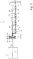
figure 2 is a schematic view of the drivetrain offigure 1 ; -
figure 3 is a schematic view of the drivetrain offigure 1 , highlighting the path of two distinct torques transmitted by the two clutches; and -
figure 4 is a block diagram of a control logic implemented in a control unit of the drivetrain. - In
figure 1 ,number 1 indicates, as a whole, a road vehicle (in particular, a car) provided with two front driven (namely, non-drive)wheels 2 and with tworear drive wheels 3. In a front position there is aninternal combustion engine 4, which is provided with adrive shaft 5, which produces a torque, which is transmitted to thedrive wheels 3 by means of a drivetrain 6. The drivetrain 6 comprises a dual-clutch, servo-assisted transmission 7 arranged in the rear-wheel-drive assembly and atransmission shaft 8, which connects thedrive shaft 5 to an input of the dual-clutch, servo-assisted transmission 7. The dual-clutch, servo-assisted transmission 7 is connected, in a train-like manner, to a self-lockingdifferential 9, from which a pair ofaxle shafts 10 start, each integral to adrive wheel 3. - The
road vehicle 1 comprises acontrol unit 11 of theengine 4, which controls theengine 4, acontrol unit 12 of the drivetrain 6, which controls the drivetrain 6, and aBUS line 13, which is manufactured, for example, according to the CAN (Car Area Network) protocol, extends to theentire road vehicle 1 and allows the twocontrol units control unit 11 of theengine 4 and thecontrol unit 12 of the drivetrain 6 are connected to theBUS line 13 and, therefore, can communicate with one another by means of messages sent through theBUS line 13. Furthermore, thecontrol unit 11 of theengine 4 and thecontrol unit 12 of the drivetrain 6 can be directly connected to one another by means of a dedicated synchronization cable 14, which is capable of directly transmitting a signal from thecontrol unit 12 of the drivetrain 6 to thecontrol unit 11 of theengine 4 without the delays caused by theBUS line 13. Alternatively, the synchronization cable 14 could be absent and all communications between the twocontrol units BUS line 13. - According to
figure 2 , the dual-clutch, servo-assisted transmission 7 comprises a pair of primary shafts 15, which are coaxial to one another, independent of one another and inserted inside one another. Furthermore, the dual-clutch, servo-assisted transmission 7 comprises two coaxial clutches 16, each designed to connect a respective primary shaft 15 to thedrive shaft 5 of theinternal combustion engine 4 through the interposition of thetransmission shaft 8; each clutch 16 is an oil bath clutch and, hence, is pressure-controlled (i.e. the degree of opening/closing of the clutch 16 is determined by the pressure of the oil inside the clutch 16); according to an alternative embodiment, each clutch 16 is a dry clutch and, hence, is position-controlled (i.e. the degree of opening/closing of the clutch 16 is determined by the position of a movable element of the clutch 16). The dual-clutch, servo-assisted transmission 7 comprises one singlesecondary shaft 17 connected to thedifferential 9 that transmits the motion to thedrive wheels 3; according to an alternative and equivalent embodiment, the dual-clutch, servo-assisted transmission 7 comprises twosecondary shafts 17, both connected to thedifferential 9. - The dual-clutch, servo-assisted transmission 7 has seven forward gears indicated with Roman numerals (first gear I, second gear II, third gear III, fourth gear IV, fifth gear V, sixth gear VI and seventh gear VII) and a reverse gear (indicated with R). The primary shaft 15 and the
secondary shaft 17 are mechanically coupled to one another by a plurality of gear trains, each defining a respective gear and comprising aprimary gear wheel 18 fitted on the primary shaft 15 and asecondary gear wheel 19 fitted on thesecondary shaft 17. In order to allow for a correct operation of the dual-clutch, servo-assisted transmission 7, all odd gears (first gear I, third gear III, fifth gear V, seventh gear VII) are coupled to a same primary shaft 15, whereas all even gears (second gear II, fourth gear IV and sixth gear VI) are coupled to the other primary shaft 15. - Each
primary gear wheel 18 is splined to a respective primary shaft 15, so as to always rotate with the primary shaft 15 in an integral manner, and permanently meshes with the respectivesecondary gear wheel 19; on the other hand, eachsecondary gear wheel 19 is mounted on thesecondary shaft 17 in an idle manner. Furthermore, the dual-clutch, servo-assisted transmission 7 comprises foursynchronizers 20, each mounted coaxial to thesecondary shaft 17, arranged between twosecondary gear wheels 19 and designed to be operated so as to alternatively fit the two respectivesecondary gear wheels 19 to the secondary shaft 17 (i.e. so as to alternatively cause the two respectivesecondary gear wheels 19 to become angularly integral to the secondary shaft 17). In other words, eachsynchronizer 20 can be moved in one direction to fit asecondary gear wheel 19 to thesecondary shaft 17 or can be moved in the other direction to fit the othersecondary gear wheel 19 to thesecondary shaft 17. - The dual-clutch transmission 7 comprises one single
secondary shaft 17 connected to thedifferential 9 that transmits the motion to thedrive wheels 3; according to an alternative and equivalent embodiment, the dual-clutch transmission 7 comprises twosecondary shafts 17, both connected to thedifferential 9. - According to
figure 1 , theroad vehicle 1 comprises a passenger compartment housing a driving position for the driver; the driving position comprises a seat (which is not shown), asteering wheel 21, anaccelerator pedal 22, abrake pedal 23 and twopaddle shifters steering wheel 21. Theupshift paddle shifter 24 is operated by the driver (by means of a short pressure) in order to request an upshift (namely, the engagement of a new gear, which is higher than the current gear and contiguous with the current gear), whereas thedownshift paddle shifter 25 is operated by the driver (by means of short pressure) in order to request a downshift (namely, the engagement of a new gear, which is lower than the current gear and is contiguous with the current gear). - In use, the
control unit 12 of the drivetrain 6 detects when theroad vehicle 1 is standing still with theinternal combustion engine 4 turned on and, in this condition (and only in this condition), thecontrol unit 12 of the drivetrain 6 engages a forward gear (normally the first gear I) that is associated with theclutch 16A (associated with all odd gears), engages the reverse gear R associated with theclutch 16B (associated with all even gears), which is different from and independent of theclutch 16A; subsequently, likefigure 3 schematically shows, when theroad vehicle 1 is standing still with theinternal combustion engine 4 turned on, thecontrol unit 12 of the drivetrain 6 closes theclutch 16A so as to cause theclutch 16A to transmit a torque TA and closes theclutch 16B so as to cause theclutch 16B to transmit a torque TB, which is equal to the torque TA multiplied by the quotient between a gear ratio of the reverse gear R and a gear ratio of the forward gear (namely, of the first gear I) . In this way, thesecondary shaft 17 of the transmission 7 is subjected, as a whole, to a zero torque, since, in thesecondary shaft 17, the two torques TA and TB have the same absolute values and opposite directions so that, therefore, they cancel one another out. - By way of example, the torque TA ranges from 3 to 7 Nm, namely the torque TA ranges from 0.4% to 0.9% of a maximum torque of the
internal combustion engine 4; as a consequence, the torque TA (and also the torque TB, which is similar to the torque TA, since the gear ratio of the reverse gear R is similar to the gear ratio of the first gear I) is very small. Indeed, the function of the torques TA and TB transmitted by the twoclutches internal combustion engine 4 in order to continue idling moves the engine point to more favourable work conditions, which decrease combustion irregularities and, hence, decrease those mechanical stresses that can produce mechanical noises. - It is evident that, in these conditions, both
clutches figure 2 ) rotates at the same rotation speed ωE as theinternal combustion engine 4 and a driven disc 27 (which is schematically shown infigure 2 ) is still (since theroad vehicle 1 must remain still). However, since the rotation speed ωE of theinternal combustion engine 4 is moderate (theinternal combustion engine 4 idles) and the torques TA and TB transmitted by the twoclutches clutches - According to a preferred embodiment schematically shown in
figure 4 , thecontrol unit 12 of the drivetrain 6 detects a rotation speed ω2 of asecondary shaft 17 of the transmission 7 (for example by means of asensor 28, which is directly or indirectly connected to thesecondary shaft 17 of the transmission 7) and modulates the torque TA and/or the torque TB based on the rotation speed ω2 of thesecondary shaft 17 of the transmission 7 and so as to cause the rotation speed ω2 of thesecondary shaft 17 of the transmission 7 to remain zero. In other words, thecontrol unit 12 of the drivetrain 6 modulates the torque TA and/or the torque TB so as to cause the rotation speed ω2 of thesecondary shaft 17 of the transmission 7 to become (and remain) zero (since, as already mentioned above, theroad vehicle 1 does not need to move) . - According to a preferred embodiment shown in
figure 4 , thecontrol unit 12 of the drivetrain 6 implements a feedback control to modulate the torque TA and/or the torque TB; in the feedback control, the control error ε is equal to the difference between zero (which represents the target value) and the rotation speed ω2 of thesecondary shaft 17 of the transmission 7. In particular, the feedback control entails the use of asubtracter block 29, which calculates the control error ε by determining the difference between zero (which represents the target value) and the rotation speed ω2 of thesecondary shaft 17 of the transmission 7, and also entails the use of aPID controller 30, which receives, as an input, the control error ε and produces, as an output, the torque TA and the torque TB with which to control theclutch 16A and theclutch 16B, respectively. - The
PID controller 30 also receives an initial torque To (other than zero) and, at first, the torque TA is assumed to be equal to the initial torque T0 (the torque TB is calculated accordingly depending on the gear ratios of the gears involved); subsequently and if necessary, thePID controller 30 changes the value of the torque TA (initially equal to the value of the initial torque To) and/or the value of the torque TB (initially derived from the value of the initial torque To through the gear ratios of the gears involved) based on the control error ε. If the control error ε always is (substantially) zero, then the value of the torque TA remains equal to the value of the initial torque T0 and the value of the torque TB remains derived from the value of the initial torque To (through the gear ratios of the gears involved). - According to a preferred embodiment, when the rotation speed ω2 of the
secondary shaft 17 of the transmission 7 is not zero, the torque TA or TB acting in the same direction as the rotation speed ω2 of thesecondary shaft 17 of the transmission 7 is decreased (rather than increasing the torque TA or TB acting in an opposite direction relative to the rotation speed ω2 of thesecondary shaft 17 of the transmission 7); in this way, the torques TA and TB, which always have to remain small, are prevented from excessively increasing. - According to a preferred embodiment, the
control unit 12 of the drivetrain 6 opens bothclutches secondary shaft 17 of the transmission 7 exceeds, in absolute value, a safety threshold, since it is preferable to have a mechanical noise rather than causing a movement of theroad vehicle 1 that can be perceived by the driver (who, on the contrary, expects theroad vehicle 1 to remain still). - The control modes described above with reference to the rotation speed ω2 of the
secondary shaft 17 of the transmission 7 can be implemented, as an alternative, not using the rotation speed ω2 of thesecondary shaft 17 of the transmission 7, but using, instead of that, the angular position of thesecondary shaft 17 of the transmission 7 (which is the time integral of the rotation speed ω2 of thesecondary shaft 17 of the transmission 7 and, hence, simply is the rotation speed ω2 of thesecondary shaft 17 of the transmission 7 in another form, namely is a transform of the rotation speed ω2 of thesecondary shaft 17 of the transmission 7). - According to a preferred embodiment, the
control unit 12 of the drivetrain 6 opens bothclutches road vehicle 1 is opened, since, due to evident personal safety reasons, when someone is getting into or out of theroad vehicle 1, there has to be no possibility at all that theroad vehicle 1 moves. - According to a preferred embodiment, the
control unit 12 of the drivetrain 6, cyclically and after a given amount of time (for example 20-30 seconds) has elapsed since the closing of theclutches clutches clutches control valves 32 controlling the feeding of oil to theclutches control valves 32, and finally closes theclutches control valves 32. Indeed, when thecontrol valves 32 remain almost closed for a long time (namely, when they remain half-open, which is necessary when theclutches clutches control valves 32 by means of a shake of thecontrol valves 32. In other words, the half-closed position of thecontrol valves 32, if it lasts for a long time, can cause thecontrol valves 32 to block or jam; therefore, at regular time intervals, thecontrol valves 32 are shaken so as to ensure that they can be controlled. - The embodiments described herein can be combined with one another, without for this reason going beyond the scope of protection of the invention.
- The control method described above has different advantages.
- First of all, the control method described above avoids the generation of a mechanical noise (often identified with the expression "cobbled sound") that can be perceived by the driver when the
road vehicle 1 is standing still with theinternal combustion engine 4 turned on. This result is obtained thanks to the fact that the entire drivetrain 6 downstream of theclutches clutches - Furthermore, the control method described above is easy and economic to be implemented as its execution requires a limited memory space and a reduced calculation ability.
-
- 1
- road vehicle
- 2
- front wheels
- 3
- rear wheels
- 4
- engine
- 5
- drive shaft
- 6
- drivetrain
- 7
- transmission
- 8
- transmission shaft
- 9
- differential
- 10
- axle shafts
- 11
- engine control unit
- 12
- drivetrain control unit
- 13
- BUS line
- 14
- synchronization cable
- 15
- primary shafts
- 16
- clutches
- 17
- secondary shaft
- 18
- primary gear wheel
- 19
- secondary gear wheel
- 20
- synchronizers
- 21
- steering wheel
- 22
- accelerator pedal
- 23
- brake pedal
- 24
- upshift paddle shifter
- 25
- downshift paddle shifter
- 26
- driving disc
- 27
- driven disc
- 28
- sensor
- 29
- subtracter block
- 30
- PID controlled
- 31
- calculation block
- 32
- control valves
- ωE
- rotation speed
- ω2
- rotation speed
- T0
- initial torque
- TA
- torque
- TB
- torque
- ε
- control error
Claims (12)
- A method to control a road vehicle (1) provided with a dual-clutch, servo-assisted transmission (7) and standing still with the internal combustion engine (4) turned on; the control method comprises, when the road vehicle (1) is standing still with the internal combustion engine (4) turned on, the steps of:engaging a forward gear associated with a first clutch (16A) ;engaging a reverse gear (R) associated with a second clutch (16B), which is different from and independent of the first clutch (16A);closing the first clutch (16A) so as to cause the first clutch (16A) to transmit a first torque (TA); andclosing the second clutch (16B) so as to cause the second clutch (16B) to transmit a second torque (TB), which is equal to the first torque (TA) multiplied by the quotient between a gear ratio of the reverse gear (R) and a gear ratio of the forward gear;the control method is characterized in that it comprises the further steps of:detecting a rotation speed (ω2) of a secondary shaft (17) of the transmission (7); andmodulating the first torque (TA) and/or the second torque (TB) depending on the rotation speed (ω2) of the secondary shaft (17) of the transmission (7).
- The control method according to claim 1, wherein the first torque (TA) ranges from 3 to 7 Nm.
- The control method according to claim 1 or 2, wherein the first torque (TA) ranges from 0.4% to 0.9% of a maximum torque of the internal combustion engine (4).
- The control method according to claim 1, 2 or 3, wherein both clutches (16A, 16B) operate in slip mode, as, in each clutch, a driving disc (26) rotates at the same rotation speed (ωE) as the internal combustion engine (4) and a driven disc (27) is still.
- The control method according to one of the claims from 1 to 4, wherein the rotation speed (ω2) of the secondary shaft (17) of the transmission (7) is measured by a sensor (28) connected to the secondary shaft (17).
- The control method according to one of the claims from 1 to 5, wherein the first torque (TA) and/or the second torque (TB) are modulated so as to cause the rotation speed (ω2) of the secondary shaft (17) of the transmission (7) to be zero.
- The control method according to claim 6, wherein the first torque (TA) and/or the second torque (TB) are modulated by means of a feedback control in which a control error (ε) is the difference between zero and the rotation speed (ω2) of the secondary shaft (17) of the transmission (7).
- The control method according to claim 7, wherein the first torque (TA) and/or the second torque (TB) are modulated by a PID controller (30) which receives, as an input, the control error (ε).
- The control method according to one of the claims from 1 to 8, wherein, when the rotation speed (ω2) of the secondary shaft (17) of the transmission (7) is not zero, the torque (TA, TB) acting in the same direction as the rotation speed (ω2) of the secondary shaft (17) of the transmission (7) is decreased.
- The control method according to one of the claims from 1 to 9, wherein, if the rotation speed (ω2) of the secondary shaft (17) of the transmission (7) exceeds, in absolute value, a safety threshold, both clutches (16A, 16B) are opened.
- The control method according to one of the claims from 1 to 10, wherein, if a door of the road vehicle (1) is opened, both clutches (16A, 16B) are opened.
- The control method according to one of the claims from 1 to 11 and comprising, cyclically and after a given amount of time has elapsed since the closing of the clutches (16A, 16B), the further steps of:opening both clutches (16A, 16B);quickly and repeatedly opening and closing, when both clutches (16A, 16B) are open, control valves (32) controlling the feeding of oil to the clutches (16A, 16B), so as to clean the control valves (32); andclosing the clutches (16A, 16B) again after having cleaned the control valves (32).
Applications Claiming Priority (1)
| Application Number | Priority Date | Filing Date | Title |
|---|---|---|---|
| IT102019000017504A IT201900017504A1 (en) | 2019-09-30 | 2019-09-30 | METHOD OF CONTROL OF A ROAD VEHICLE EQUIPPED WITH A POWER-ASSISTED TRANSMISSION WITH DOUBLE CLUTCH AND STOPPING WITH THE INTERNAL COMBUSTION ENGINE ON |
Publications (2)
| Publication Number | Publication Date |
|---|---|
| EP3798474A1 true EP3798474A1 (en) | 2021-03-31 |
| EP3798474B1 EP3798474B1 (en) | 2022-04-20 |
Family
ID=69701243
Family Applications (1)
| Application Number | Title | Priority Date | Filing Date |
|---|---|---|---|
| EP20199357.3A Active EP3798474B1 (en) | 2019-09-30 | 2020-09-30 | Method to control a road vehicle provided with a dual-clutch, servo-assisted transmission and standing still with the internal combustion engine turned on |
Country Status (5)
| Country | Link |
|---|---|
| US (1) | US11173908B2 (en) |
| EP (1) | EP3798474B1 (en) |
| JP (1) | JP7506569B2 (en) |
| CN (1) | CN112576740B (en) |
| IT (1) | IT201900017504A1 (en) |
Citations (2)
| Publication number | Priority date | Publication date | Assignee | Title |
|---|---|---|---|---|
| DE102007056767A1 (en) * | 2007-11-23 | 2009-05-28 | Gertrag Ford Transmissions Gmbh | Method for operating pressure control valve of pressure system for actuating clutch, involves modulating pressure in temporally variable manner during operation of clutch in which clutch has constant torsional capacity |
| US20110284336A1 (en) | 2009-02-20 | 2011-11-24 | Bayerische Motoren Werke Aktiengesellschaft | Method for Reducing the Noise in the Drive Train of a Motor Vehicle |
Family Cites Families (14)
| Publication number | Priority date | Publication date | Assignee | Title |
|---|---|---|---|---|
| SE524662C2 (en) * | 2003-01-14 | 2004-09-14 | Volvo Lastvagnar Ab | Changeover procedure for vehicles with coupled coupling dependent power take-off |
| JP2007192322A (en) | 2006-01-19 | 2007-08-02 | Hitachi Ltd | Control device and control method for automatic transmission |
| JP2007315475A (en) | 2006-05-25 | 2007-12-06 | Toyota Motor Corp | Hydraulic control device for vehicle transmission |
| EP1995144B1 (en) * | 2007-05-21 | 2013-05-01 | Magneti Marelli S.p.A. | Method and system for controlling a vehicle provided with a servo mechanical gear-change |
| JP5109929B2 (en) | 2008-10-23 | 2012-12-26 | トヨタ自動車株式会社 | Internal combustion engine start control device |
| ITBO20090159A1 (en) * | 2009-03-18 | 2010-09-19 | Ferrari Spa | CONTROL METHOD FOR THE PERFORMANCE OF AN ASCENDING GEAR SHIFT IN AN AUTOMATIC MANUAL TRANSMISSION PROVIDED WITH A DOUBLE CLUTCH CHANGE |
| KR101132454B1 (en) * | 2009-12-14 | 2012-03-30 | 강명구 | Operating mechanism of a triple clutch transmission |
| US8600633B2 (en) * | 2010-07-29 | 2013-12-03 | GM Global Technology Operations LLC | Gear preselect systems for a dual clutch transmission |
| JP6088726B2 (en) | 2011-07-04 | 2017-03-01 | いすゞ自動車株式会社 | Dual clutch transmission control method, dual clutch transmission and vehicle equipped with the same |
| JP5787703B2 (en) * | 2011-10-04 | 2015-09-30 | アイシン・エーアイ株式会社 | Dual clutch automatic transmission |
| JP5847521B2 (en) * | 2011-10-05 | 2016-01-20 | アイシン・エーアイ株式会社 | Dual clutch automatic transmission |
| JP6114128B2 (en) * | 2013-07-05 | 2017-04-12 | 本田技研工業株式会社 | Automatic transmission |
| JP6197842B2 (en) * | 2015-09-02 | 2017-09-20 | トヨタ自動車株式会社 | Vehicle control device |
| US10377365B2 (en) * | 2017-11-13 | 2019-08-13 | Iseki & Co., Ltd. | Work vehicle |
-
2019
- 2019-09-30 IT IT102019000017504A patent/IT201900017504A1/en unknown
-
2020
- 2020-09-09 US US17/015,351 patent/US11173908B2/en active Active
- 2020-09-23 JP JP2020158620A patent/JP7506569B2/en active Active
- 2020-09-29 CN CN202011053528.7A patent/CN112576740B/en active Active
- 2020-09-30 EP EP20199357.3A patent/EP3798474B1/en active Active
Patent Citations (2)
| Publication number | Priority date | Publication date | Assignee | Title |
|---|---|---|---|---|
| DE102007056767A1 (en) * | 2007-11-23 | 2009-05-28 | Gertrag Ford Transmissions Gmbh | Method for operating pressure control valve of pressure system for actuating clutch, involves modulating pressure in temporally variable manner during operation of clutch in which clutch has constant torsional capacity |
| US20110284336A1 (en) | 2009-02-20 | 2011-11-24 | Bayerische Motoren Werke Aktiengesellschaft | Method for Reducing the Noise in the Drive Train of a Motor Vehicle |
Also Published As
| Publication number | Publication date |
|---|---|
| CN112576740A (en) | 2021-03-30 |
| IT201900017504A1 (en) | 2021-03-30 |
| JP7506569B2 (en) | 2024-06-26 |
| US11173908B2 (en) | 2021-11-16 |
| US20210094545A1 (en) | 2021-04-01 |
| EP3798474B1 (en) | 2022-04-20 |
| JP2021055837A (en) | 2021-04-08 |
| CN112576740B (en) | 2023-12-08 |
Similar Documents
| Publication | Publication Date | Title |
|---|---|---|
| EP1209015B1 (en) | Apparatus for determining the clutch engagement state in a hybrid vehicle and gear shift control using the same apparatus | |
| JP7278040B2 (en) | Method for controlling gearshift phases in hybrid vehicles provided with automated manual transmissions and corresponding transmission systems for hybrid vehicles | |
| CN112572441B (en) | Method for controlling a road vehicle to perform a static start | |
| EP2226230B1 (en) | Control method of shifting gear in an automatic manual transmission | |
| US7721834B2 (en) | Prevention of inadvertent inertial engagement of a transfer case clutch | |
| EP3798474B1 (en) | Method to control a road vehicle provided with a dual-clutch, servo-assisted transmission and standing still with the internal combustion engine turned on | |
| US8825325B2 (en) | Control method for closing a clutch in an automatic manual transmission | |
| US11248667B2 (en) | Method to control a road vehicle with a microslip of the clutch | |
| JP7651284B2 (en) | Method for controlling a road vehicle with a servo-assisted transmission during a deceleration phase - Patents.com | |
| CN112572448B (en) | Method for controlling a road vehicle by performing a multi-step downshift in a powertrain having a servo-assisted gearbox | |
| CN112572447A (en) | Method for controlling a shift to a higher gear with the accelerator pedal released | |
| US11215279B2 (en) | Method to automatically control a drivetrain provided with a servo-assisted transmission |
Legal Events
| Date | Code | Title | Description |
|---|---|---|---|
| PUAI | Public reference made under article 153(3) epc to a published international application that has entered the european phase |
Free format text: ORIGINAL CODE: 0009012 |
|
| STAA | Information on the status of an ep patent application or granted ep patent |
Free format text: STATUS: THE APPLICATION HAS BEEN PUBLISHED |
|
| AK | Designated contracting states |
Kind code of ref document: A1 Designated state(s): AL AT BE BG CH CY CZ DE DK EE ES FI FR GB GR HR HU IE IS IT LI LT LU LV MC MK MT NL NO PL PT RO RS SE SI SK SM TR |
|
| AX | Request for extension of the european patent |
Extension state: BA ME |
|
| STAA | Information on the status of an ep patent application or granted ep patent |
Free format text: STATUS: REQUEST FOR EXAMINATION WAS MADE |
|
| 17P | Request for examination filed |
Effective date: 20210825 |
|
| GRAP | Despatch of communication of intention to grant a patent |
Free format text: ORIGINAL CODE: EPIDOSNIGR1 |
|
| STAA | Information on the status of an ep patent application or granted ep patent |
Free format text: STATUS: GRANT OF PATENT IS INTENDED |
|
| RIC1 | Information provided on ipc code assigned before grant |
Ipc: F16H 59/50 20060101ALN20210916BHEP Ipc: F16H 59/40 20060101ALN20210916BHEP Ipc: F16H 57/00 20120101ALI20210916BHEP Ipc: F16H 61/688 20060101ALI20210916BHEP Ipc: F16H 61/00 20060101AFI20210916BHEP |
|
| INTG | Intention to grant announced |
Effective date: 20211018 |
|
| GRAS | Grant fee paid |
Free format text: ORIGINAL CODE: EPIDOSNIGR3 |
|
| GRAA | (expected) grant |
Free format text: ORIGINAL CODE: 0009210 |
|
| STAA | Information on the status of an ep patent application or granted ep patent |
Free format text: STATUS: THE PATENT HAS BEEN GRANTED |
|
| AK | Designated contracting states |
Kind code of ref document: B1 Designated state(s): AL AT BE BG CH CY CZ DE DK EE ES FI FR GB GR HR HU IE IS IT LI LT LU LV MC MK MT NL NO PL PT RO RS SE SI SK SM TR |
|
| REG | Reference to a national code |
Ref country code: GB Ref legal event code: FG4D |
|
| REG | Reference to a national code |
Ref country code: CH Ref legal event code: EP |
|
| REG | Reference to a national code |
Ref country code: IE Ref legal event code: FG4D |
|
| REG | Reference to a national code |
Ref country code: DE Ref legal event code: R096 Ref document number: 602020002755 Country of ref document: DE |
|
| REG | Reference to a national code |
Ref country code: AT Ref legal event code: REF Ref document number: 1485383 Country of ref document: AT Kind code of ref document: T Effective date: 20220515 |
|
| REG | Reference to a national code |
Ref country code: LT Ref legal event code: MG9D |
|
| REG | Reference to a national code |
Ref country code: NL Ref legal event code: MP Effective date: 20220420 |
|
| REG | Reference to a national code |
Ref country code: AT Ref legal event code: MK05 Ref document number: 1485383 Country of ref document: AT Kind code of ref document: T Effective date: 20220420 |
|
| PG25 | Lapsed in a contracting state [announced via postgrant information from national office to epo] |
Ref country code: NL Free format text: LAPSE BECAUSE OF FAILURE TO SUBMIT A TRANSLATION OF THE DESCRIPTION OR TO PAY THE FEE WITHIN THE PRESCRIBED TIME-LIMIT Effective date: 20220420 |
|
| PG25 | Lapsed in a contracting state [announced via postgrant information from national office to epo] |
Ref country code: SE Free format text: LAPSE BECAUSE OF FAILURE TO SUBMIT A TRANSLATION OF THE DESCRIPTION OR TO PAY THE FEE WITHIN THE PRESCRIBED TIME-LIMIT Effective date: 20220420 Ref country code: PT Free format text: LAPSE BECAUSE OF FAILURE TO SUBMIT A TRANSLATION OF THE DESCRIPTION OR TO PAY THE FEE WITHIN THE PRESCRIBED TIME-LIMIT Effective date: 20220822 Ref country code: NO Free format text: LAPSE BECAUSE OF FAILURE TO SUBMIT A TRANSLATION OF THE DESCRIPTION OR TO PAY THE FEE WITHIN THE PRESCRIBED TIME-LIMIT Effective date: 20220720 Ref country code: LT Free format text: LAPSE BECAUSE OF FAILURE TO SUBMIT A TRANSLATION OF THE DESCRIPTION OR TO PAY THE FEE WITHIN THE PRESCRIBED TIME-LIMIT Effective date: 20220420 Ref country code: HR Free format text: LAPSE BECAUSE OF FAILURE TO SUBMIT A TRANSLATION OF THE DESCRIPTION OR TO PAY THE FEE WITHIN THE PRESCRIBED TIME-LIMIT Effective date: 20220420 Ref country code: GR Free format text: LAPSE BECAUSE OF FAILURE TO SUBMIT A TRANSLATION OF THE DESCRIPTION OR TO PAY THE FEE WITHIN THE PRESCRIBED TIME-LIMIT Effective date: 20220721 Ref country code: FI Free format text: LAPSE BECAUSE OF FAILURE TO SUBMIT A TRANSLATION OF THE DESCRIPTION OR TO PAY THE FEE WITHIN THE PRESCRIBED TIME-LIMIT Effective date: 20220420 Ref country code: ES Free format text: LAPSE BECAUSE OF FAILURE TO SUBMIT A TRANSLATION OF THE DESCRIPTION OR TO PAY THE FEE WITHIN THE PRESCRIBED TIME-LIMIT Effective date: 20220420 Ref country code: BG Free format text: LAPSE BECAUSE OF FAILURE TO SUBMIT A TRANSLATION OF THE DESCRIPTION OR TO PAY THE FEE WITHIN THE PRESCRIBED TIME-LIMIT Effective date: 20220720 Ref country code: AT Free format text: LAPSE BECAUSE OF FAILURE TO SUBMIT A TRANSLATION OF THE DESCRIPTION OR TO PAY THE FEE WITHIN THE PRESCRIBED TIME-LIMIT Effective date: 20220420 |
|
| PG25 | Lapsed in a contracting state [announced via postgrant information from national office to epo] |
Ref country code: RS Free format text: LAPSE BECAUSE OF FAILURE TO SUBMIT A TRANSLATION OF THE DESCRIPTION OR TO PAY THE FEE WITHIN THE PRESCRIBED TIME-LIMIT Effective date: 20220420 Ref country code: PL Free format text: LAPSE BECAUSE OF FAILURE TO SUBMIT A TRANSLATION OF THE DESCRIPTION OR TO PAY THE FEE WITHIN THE PRESCRIBED TIME-LIMIT Effective date: 20220420 Ref country code: LV Free format text: LAPSE BECAUSE OF FAILURE TO SUBMIT A TRANSLATION OF THE DESCRIPTION OR TO PAY THE FEE WITHIN THE PRESCRIBED TIME-LIMIT Effective date: 20220420 Ref country code: IS Free format text: LAPSE BECAUSE OF FAILURE TO SUBMIT A TRANSLATION OF THE DESCRIPTION OR TO PAY THE FEE WITHIN THE PRESCRIBED TIME-LIMIT Effective date: 20220820 |
|
| REG | Reference to a national code |
Ref country code: DE Ref legal event code: R097 Ref document number: 602020002755 Country of ref document: DE |
|
| PG25 | Lapsed in a contracting state [announced via postgrant information from national office to epo] |
Ref country code: SM Free format text: LAPSE BECAUSE OF FAILURE TO SUBMIT A TRANSLATION OF THE DESCRIPTION OR TO PAY THE FEE WITHIN THE PRESCRIBED TIME-LIMIT Effective date: 20220420 Ref country code: SK Free format text: LAPSE BECAUSE OF FAILURE TO SUBMIT A TRANSLATION OF THE DESCRIPTION OR TO PAY THE FEE WITHIN THE PRESCRIBED TIME-LIMIT Effective date: 20220420 Ref country code: RO Free format text: LAPSE BECAUSE OF FAILURE TO SUBMIT A TRANSLATION OF THE DESCRIPTION OR TO PAY THE FEE WITHIN THE PRESCRIBED TIME-LIMIT Effective date: 20220420 Ref country code: EE Free format text: LAPSE BECAUSE OF FAILURE TO SUBMIT A TRANSLATION OF THE DESCRIPTION OR TO PAY THE FEE WITHIN THE PRESCRIBED TIME-LIMIT Effective date: 20220420 Ref country code: DK Free format text: LAPSE BECAUSE OF FAILURE TO SUBMIT A TRANSLATION OF THE DESCRIPTION OR TO PAY THE FEE WITHIN THE PRESCRIBED TIME-LIMIT Effective date: 20220420 Ref country code: CZ Free format text: LAPSE BECAUSE OF FAILURE TO SUBMIT A TRANSLATION OF THE DESCRIPTION OR TO PAY THE FEE WITHIN THE PRESCRIBED TIME-LIMIT Effective date: 20220420 |
|
| PLBE | No opposition filed within time limit |
Free format text: ORIGINAL CODE: 0009261 |
|
| STAA | Information on the status of an ep patent application or granted ep patent |
Free format text: STATUS: NO OPPOSITION FILED WITHIN TIME LIMIT |
|
| 26N | No opposition filed |
Effective date: 20230123 |
|
| PG25 | Lapsed in a contracting state [announced via postgrant information from national office to epo] |
Ref country code: AL Free format text: LAPSE BECAUSE OF FAILURE TO SUBMIT A TRANSLATION OF THE DESCRIPTION OR TO PAY THE FEE WITHIN THE PRESCRIBED TIME-LIMIT Effective date: 20220420 |
|
| PG25 | Lapsed in a contracting state [announced via postgrant information from national office to epo] |
Ref country code: MC Free format text: LAPSE BECAUSE OF FAILURE TO SUBMIT A TRANSLATION OF THE DESCRIPTION OR TO PAY THE FEE WITHIN THE PRESCRIBED TIME-LIMIT Effective date: 20220420 |
|
| REG | Reference to a national code |
Ref country code: BE Ref legal event code: MM Effective date: 20220930 |
|
| PG25 | Lapsed in a contracting state [announced via postgrant information from national office to epo] |
Ref country code: SI Free format text: LAPSE BECAUSE OF FAILURE TO SUBMIT A TRANSLATION OF THE DESCRIPTION OR TO PAY THE FEE WITHIN THE PRESCRIBED TIME-LIMIT Effective date: 20220420 |
|
| PG25 | Lapsed in a contracting state [announced via postgrant information from national office to epo] |
Ref country code: LU Free format text: LAPSE BECAUSE OF NON-PAYMENT OF DUE FEES Effective date: 20220930 |
|
| P01 | Opt-out of the competence of the unified patent court (upc) registered |
Effective date: 20230525 |
|
| PG25 | Lapsed in a contracting state [announced via postgrant information from national office to epo] |
Ref country code: IE Free format text: LAPSE BECAUSE OF NON-PAYMENT OF DUE FEES Effective date: 20220930 |
|
| PG25 | Lapsed in a contracting state [announced via postgrant information from national office to epo] |
Ref country code: BE Free format text: LAPSE BECAUSE OF NON-PAYMENT OF DUE FEES Effective date: 20220930 |
|
| PG25 | Lapsed in a contracting state [announced via postgrant information from national office to epo] |
Ref country code: CY Free format text: LAPSE BECAUSE OF FAILURE TO SUBMIT A TRANSLATION OF THE DESCRIPTION OR TO PAY THE FEE WITHIN THE PRESCRIBED TIME-LIMIT Effective date: 20220420 |
|
| REG | Reference to a national code |
Ref country code: CH Ref legal event code: PL |
|
| PG25 | Lapsed in a contracting state [announced via postgrant information from national office to epo] |
Ref country code: MK Free format text: LAPSE BECAUSE OF FAILURE TO SUBMIT A TRANSLATION OF THE DESCRIPTION OR TO PAY THE FEE WITHIN THE PRESCRIBED TIME-LIMIT Effective date: 20220420 |
|
| PG25 | Lapsed in a contracting state [announced via postgrant information from national office to epo] |
Ref country code: TR Free format text: LAPSE BECAUSE OF FAILURE TO SUBMIT A TRANSLATION OF THE DESCRIPTION OR TO PAY THE FEE WITHIN THE PRESCRIBED TIME-LIMIT Effective date: 20220420 |
|
| PG25 | Lapsed in a contracting state [announced via postgrant information from national office to epo] |
Ref country code: CH Free format text: LAPSE BECAUSE OF NON-PAYMENT OF DUE FEES Effective date: 20230930 |
|
| PG25 | Lapsed in a contracting state [announced via postgrant information from national office to epo] |
Ref country code: HU Free format text: LAPSE BECAUSE OF FAILURE TO SUBMIT A TRANSLATION OF THE DESCRIPTION OR TO PAY THE FEE WITHIN THE PRESCRIBED TIME-LIMIT; INVALID AB INITIO Effective date: 20200930 Ref country code: CH Free format text: LAPSE BECAUSE OF NON-PAYMENT OF DUE FEES Effective date: 20230930 |
|
| PG25 | Lapsed in a contracting state [announced via postgrant information from national office to epo] |
Ref country code: MT Free format text: LAPSE BECAUSE OF FAILURE TO SUBMIT A TRANSLATION OF THE DESCRIPTION OR TO PAY THE FEE WITHIN THE PRESCRIBED TIME-LIMIT Effective date: 20220420 |
|
| PG25 | Lapsed in a contracting state [announced via postgrant information from national office to epo] |
Ref country code: BG Free format text: LAPSE BECAUSE OF FAILURE TO SUBMIT A TRANSLATION OF THE DESCRIPTION OR TO PAY THE FEE WITHIN THE PRESCRIBED TIME-LIMIT Effective date: 20220420 |
|
| PG25 | Lapsed in a contracting state [announced via postgrant information from national office to epo] |
Ref country code: BG Free format text: LAPSE BECAUSE OF FAILURE TO SUBMIT A TRANSLATION OF THE DESCRIPTION OR TO PAY THE FEE WITHIN THE PRESCRIBED TIME-LIMIT Effective date: 20220420 |
|
| PGFP | Annual fee paid to national office [announced via postgrant information from national office to epo] |
Ref country code: DE Payment date: 20250926 Year of fee payment: 6 |
|
| PGFP | Annual fee paid to national office [announced via postgrant information from national office to epo] |
Ref country code: IT Payment date: 20250908 Year of fee payment: 6 |
|
| PGFP | Annual fee paid to national office [announced via postgrant information from national office to epo] |
Ref country code: GB Payment date: 20250923 Year of fee payment: 6 |
|
| PGFP | Annual fee paid to national office [announced via postgrant information from national office to epo] |
Ref country code: FR Payment date: 20250925 Year of fee payment: 6 |