EP3798417A1 - Multi-flow cooling circuit for gas turbine engine flowpath component - Google Patents
Multi-flow cooling circuit for gas turbine engine flowpath component Download PDFInfo
- Publication number
- EP3798417A1 EP3798417A1 EP20196540.7A EP20196540A EP3798417A1 EP 3798417 A1 EP3798417 A1 EP 3798417A1 EP 20196540 A EP20196540 A EP 20196540A EP 3798417 A1 EP3798417 A1 EP 3798417A1
- Authority
- EP
- European Patent Office
- Prior art keywords
- vane
- internal cooling
- vanes
- gas turbine
- cooling
- Prior art date
- Legal status (The legal status is an assumption and is not a legal conclusion. Google has not performed a legal analysis and makes no representation as to the accuracy of the status listed.)
- Pending
Links
Images


Classifications
-
- F—MECHANICAL ENGINEERING; LIGHTING; HEATING; WEAPONS; BLASTING
- F01—MACHINES OR ENGINES IN GENERAL; ENGINE PLANTS IN GENERAL; STEAM ENGINES
- F01D—NON-POSITIVE DISPLACEMENT MACHINES OR ENGINES, e.g. STEAM TURBINES
- F01D5/00—Blades; Blade-carrying members; Heating, heat-insulating, cooling or antivibration means on the blades or the members
- F01D5/12—Blades
- F01D5/14—Form or construction
- F01D5/18—Hollow blades, i.e. blades with cooling or heating channels or cavities; Heating, heat-insulating or cooling means on blades
- F01D5/187—Convection cooling
-
- F—MECHANICAL ENGINEERING; LIGHTING; HEATING; WEAPONS; BLASTING
- F01—MACHINES OR ENGINES IN GENERAL; ENGINE PLANTS IN GENERAL; STEAM ENGINES
- F01D—NON-POSITIVE DISPLACEMENT MACHINES OR ENGINES, e.g. STEAM TURBINES
- F01D5/00—Blades; Blade-carrying members; Heating, heat-insulating, cooling or antivibration means on the blades or the members
- F01D5/12—Blades
- F01D5/14—Form or construction
- F01D5/18—Hollow blades, i.e. blades with cooling or heating channels or cavities; Heating, heat-insulating or cooling means on blades
- F01D5/186—Film cooling
-
- F—MECHANICAL ENGINEERING; LIGHTING; HEATING; WEAPONS; BLASTING
- F01—MACHINES OR ENGINES IN GENERAL; ENGINE PLANTS IN GENERAL; STEAM ENGINES
- F01D—NON-POSITIVE DISPLACEMENT MACHINES OR ENGINES, e.g. STEAM TURBINES
- F01D5/00—Blades; Blade-carrying members; Heating, heat-insulating, cooling or antivibration means on the blades or the members
- F01D5/12—Blades
- F01D5/14—Form or construction
- F01D5/18—Hollow blades, i.e. blades with cooling or heating channels or cavities; Heating, heat-insulating or cooling means on blades
- F01D5/187—Convection cooling
- F01D5/188—Convection cooling with an insert in the blade cavity to guide the cooling fluid, e.g. forming a separation wall
-
- F—MECHANICAL ENGINEERING; LIGHTING; HEATING; WEAPONS; BLASTING
- F01—MACHINES OR ENGINES IN GENERAL; ENGINE PLANTS IN GENERAL; STEAM ENGINES
- F01D—NON-POSITIVE DISPLACEMENT MACHINES OR ENGINES, e.g. STEAM TURBINES
- F01D9/00—Stators
- F01D9/06—Fluid supply conduits to nozzles or the like
- F01D9/065—Fluid supply or removal conduits traversing the working fluid flow, e.g. for lubrication-, cooling-, or sealing fluids
-
- F—MECHANICAL ENGINEERING; LIGHTING; HEATING; WEAPONS; BLASTING
- F01—MACHINES OR ENGINES IN GENERAL; ENGINE PLANTS IN GENERAL; STEAM ENGINES
- F01D—NON-POSITIVE DISPLACEMENT MACHINES OR ENGINES, e.g. STEAM TURBINES
- F01D17/00—Regulating or controlling by varying flow
- F01D17/10—Final actuators
- F01D17/12—Final actuators arranged in stator parts
- F01D17/14—Final actuators arranged in stator parts varying effective cross-sectional area of nozzles or guide conduits
- F01D17/16—Final actuators arranged in stator parts varying effective cross-sectional area of nozzles or guide conduits by means of nozzle vanes
- F01D17/162—Final actuators arranged in stator parts varying effective cross-sectional area of nozzles or guide conduits by means of nozzle vanes for axial flow, i.e. the vanes turning around axes which are essentially perpendicular to the rotor centre line
-
- F—MECHANICAL ENGINEERING; LIGHTING; HEATING; WEAPONS; BLASTING
- F01—MACHINES OR ENGINES IN GENERAL; ENGINE PLANTS IN GENERAL; STEAM ENGINES
- F01D—NON-POSITIVE DISPLACEMENT MACHINES OR ENGINES, e.g. STEAM TURBINES
- F01D25/00—Component parts, details, or accessories, not provided for in, or of interest apart from, other groups
- F01D25/08—Cooling; Heating; Heat-insulation
- F01D25/12—Cooling
-
- F—MECHANICAL ENGINEERING; LIGHTING; HEATING; WEAPONS; BLASTING
- F02—COMBUSTION ENGINES; HOT-GAS OR COMBUSTION-PRODUCT ENGINE PLANTS
- F02C—GAS-TURBINE PLANTS; AIR INTAKES FOR JET-PROPULSION PLANTS; CONTROLLING FUEL SUPPLY IN AIR-BREATHING JET-PROPULSION PLANTS
- F02C9/00—Controlling gas-turbine plants; Controlling fuel supply in air- breathing jet-propulsion plants
- F02C9/16—Control of working fluid flow
- F02C9/20—Control of working fluid flow by throttling; by adjusting vanes
- F02C9/22—Control of working fluid flow by throttling; by adjusting vanes by adjusting turbine vanes
-
- F—MECHANICAL ENGINEERING; LIGHTING; HEATING; WEAPONS; BLASTING
- F04—POSITIVE - DISPLACEMENT MACHINES FOR LIQUIDS; PUMPS FOR LIQUIDS OR ELASTIC FLUIDS
- F04D—NON-POSITIVE-DISPLACEMENT PUMPS
- F04D29/00—Details, component parts, or accessories
- F04D29/40—Casings; Connections of working fluid
- F04D29/52—Casings; Connections of working fluid for axial pumps
- F04D29/54—Fluid-guiding means, e.g. diffusers
- F04D29/56—Fluid-guiding means, e.g. diffusers adjustable
- F04D29/563—Fluid-guiding means, e.g. diffusers adjustable specially adapted for elastic fluid pumps
-
- F—MECHANICAL ENGINEERING; LIGHTING; HEATING; WEAPONS; BLASTING
- F04—POSITIVE - DISPLACEMENT MACHINES FOR LIQUIDS; PUMPS FOR LIQUIDS OR ELASTIC FLUIDS
- F04D—NON-POSITIVE-DISPLACEMENT PUMPS
- F04D29/00—Details, component parts, or accessories
- F04D29/58—Cooling; Heating; Diminishing heat transfer
- F04D29/582—Cooling; Heating; Diminishing heat transfer specially adapted for elastic fluid pumps
- F04D29/5846—Cooling; Heating; Diminishing heat transfer specially adapted for elastic fluid pumps cooling by injection
-
- F—MECHANICAL ENGINEERING; LIGHTING; HEATING; WEAPONS; BLASTING
- F05—INDEXING SCHEMES RELATING TO ENGINES OR PUMPS IN VARIOUS SUBCLASSES OF CLASSES F01-F04
- F05D—INDEXING SCHEME FOR ASPECTS RELATING TO NON-POSITIVE-DISPLACEMENT MACHINES OR ENGINES, GAS-TURBINES OR JET-PROPULSION PLANTS
- F05D2260/00—Function
- F05D2260/20—Heat transfer, e.g. cooling
- F05D2260/202—Heat transfer, e.g. cooling by film cooling
-
- F—MECHANICAL ENGINEERING; LIGHTING; HEATING; WEAPONS; BLASTING
- F05—INDEXING SCHEMES RELATING TO ENGINES OR PUMPS IN VARIOUS SUBCLASSES OF CLASSES F01-F04
- F05D—INDEXING SCHEME FOR ASPECTS RELATING TO NON-POSITIVE-DISPLACEMENT MACHINES OR ENGINES, GAS-TURBINES OR JET-PROPULSION PLANTS
- F05D2260/00—Function
- F05D2260/20—Heat transfer, e.g. cooling
- F05D2260/204—Heat transfer, e.g. cooling by the use of microcircuits
-
- Y—GENERAL TAGGING OF NEW TECHNOLOGICAL DEVELOPMENTS; GENERAL TAGGING OF CROSS-SECTIONAL TECHNOLOGIES SPANNING OVER SEVERAL SECTIONS OF THE IPC; TECHNICAL SUBJECTS COVERED BY FORMER USPC CROSS-REFERENCE ART COLLECTIONS [XRACs] AND DIGESTS
- Y02—TECHNOLOGIES OR APPLICATIONS FOR MITIGATION OR ADAPTATION AGAINST CLIMATE CHANGE
- Y02T—CLIMATE CHANGE MITIGATION TECHNOLOGIES RELATED TO TRANSPORTATION
- Y02T50/00—Aeronautics or air transport
- Y02T50/60—Efficient propulsion technologies, e.g. for aircraft
Definitions
- the present disclosure relates generally to cooling circuits for a gas turbine engine flowpath component.
- Gas turbine engines such as those utilized in commercial and military aircraft, include a compressor section that compresses air, a combustor section in which the compressed air is mixed with a fuel and ignited, and a turbine section through which the resultant combustion products are expanded.
- the expansion of the combustion products drives the turbine section to rotate.
- the turbine section is connected to the compressor section via a shaft, the rotation of the turbine section further drives the compressor section to rotate.
- a fan is also connected to the shaft and is driven to rotate via rotation of the turbine as well.
- Some gas turbine engines include multiple compressor and turbine stages, each of which is defined by a pairing of flow directing rotors and vanes.
- one or more of the flowpath components within the stage can include cooling passages that expel air along the surface of the flowpath component to create a film cooling effect. Cooling air in such examples is typically provided from a flow inlet at a single end of the flowpath component.
- a flowpath component for a gas turbine engine comprising a body having a leading edge and a trailing edge, a first exterior wall connecting the leading edge to the trailing edge and a second exterior wall connecting the leading edge to the trailing edge; at least one first internal cooling passage having a first inlet at a first end of the body; at least one second internal cooling passage having a second inlet at a second end of the body; and wherein the at least one first internal cooling passage is isolated from the at least one second internal cooling passage.
- the body is a variable vane having a first angle of attack in a first vane position and a second angle of attack in a second vane position.
- the body has an airfoil profile and is configured to have a first angle of attack in a first position and a second angle of attack in a second position.
- the first end of the body is a radially outward end relative to an engine in which the flowpath component is incorporated.
- the second end of the body is a radially inward end opposite the first end.
- the component comprises a plurality of cooling film holes connecting the at least one second internal cooling passage to an exterior edge of the flowpath body.
- At least a portion of the at least one second internal cooling passage extends to the leading edge.
- the flowpath body is a first stage turbine vane.
- the flowpath body is a second or later stage turbine vane.
- the second inlet is connected to a feed through passage in an adjacent rotor hub.
- a gas turbine engine comprising a compressor section having a plurality of compressor stages, each compressor stage in the plurality of compressor stages including a set of compressor rotors and a set of compressor vanes; a combustor section fluidly connected to the compressor section and including a combustor; a turbine section fluidly connected to the combustor section and including a plurality of turbine stages, each of the turbine stages in the plurality of turbine stages including a set of rotors and a set of turbine vanes; wherein at least one of the set of compressor vanes and the set of turbine vanes comprises a set of variable vanes each vane in the set of variable vanes having a body having a leading edge and a trailing edge, a first exterior wall connecting the leading edge to the trailing edge and a second exterior wall connecting the leading edge to the trailing edge, at least one first internal cooling passage having a first inlet at a first end of the body, at least one second internal cooling passage having a
- the body has an airfoil profile and is configured to have a first angle of attack in a first position and a second angle of attack in a second position.
- the first end of the body is a radially outward end relative to a radius of the engine and the second end of the body is a radially inward end opposite the first end.
- the set of variable vanes is a subset of vanes in a single stage, and wherein the set of variable vanes are alternated with a set of fixed vanes within the stage.
- the first inlet is disposed within a spindle.
- the gas turbine engine also comprises a plurality of cooling film holes connecting the at least one second internal cooling passage to an exterior edge of the body.
- At least a portion of the at least one second internal cooling passage extends to the leading edge.
- the second inlet is connected to a feed through passage in an adjacent rotor hub.
- a method for cooling a variable vane comprising providing a first cooling flow to a first set of internal cooling passages from a first cooling flow inlet; and providing a second cooling flow to a second set of internal cooling passages from a second cooling flow inlet, the second set of internal cooling passages being isolated from the first set of internal cooling passages.
- An embodiment of the above method comprises providing the first cooling flow to the first set of internal cooling passages, and comprises providing the first cooling flow through a radially outward spindle of the variable vane, wherein providing the second cooling flow to the second set of internal cooling passages comprises providing the second cooling flow through a radially inward spindle of the variable vane, and wherein the method further includes cooling a leading edge of the variable vane and a pressure side of the variable vane using the first cooling flow and cooling a trailing edge and the suction side of the variable vane using the second cooling flow.
- FIG. 1 schematically illustrates a gas turbine engine 20.
- the gas turbine engine 20 is disclosed herein as a two-spool turbofan that generally incorporates a fan section 22, a compressor section 24, a combustor section 26 and a turbine section 28.
- the fan section 22 drives air along a bypass flow path B in a bypass duct defined within a housing 15 such as a fan case or nacelle, and also drives air along a core flow path C for compression and communication into the combustor section 26 then expansion through the turbine section 28.
- turbofan gas turbine engine Although depicted as a two-spool turbofan gas turbine engine in the disclosed non-limiting embodiment, it should be understood that the concepts described herein are not limited to use with two-spool turbofans as the teachings may be applied to other types of turbine engines including but not limited to three-spool architectures, turbofans with a direct driven fan, turbofans with a gear driven fan, and turbofans with multiple bypass flowpaths.
- the exemplary engine 20 generally includes a low speed spool 30 and a high speed spool 32 mounted for rotation about an engine central longitudinal axis A relative to an engine static structure 36 via several bearing systems 38. It should be understood that various bearing systems 38 at various locations may alternatively or additionally be provided, and the location of bearing systems 38 may be varied as appropriate to the application.
- the low speed spool 30 generally includes an inner shaft 40 that interconnects, a first (or low) pressure compressor 44 and a first (or low) pressure turbine 46.
- the inner shaft 40 is connected to the fan 42 through a speed change mechanism, which in exemplary gas turbine engine 20 is illustrated as a geared architecture 48 to drive a fan 42 at a lower speed than the low speed spool 30.
- the high speed spool 32 includes an outer shaft 50 that interconnects a second (or high) pressure compressor 52 and a second (or high) pressure turbine 54.
- a combustor 56 is arranged in exemplary gas turbine 20 between the high pressure compressor 52 and the high pressure turbine 54.
- a mid-turbine frame 57 of the engine static structure 36 may be arranged generally between the high pressure turbine 54 and the low pressure turbine 46.
- the mid-turbine frame 57 further supports bearing systems 38 in the turbine section 28.
- the inner shaft 40 and the outer shaft 50 are concentric and rotate via bearing systems 38 about the engine central longitudinal axis A which is colline
- the core airflow is compressed by the low pressure compressor 44 then the high pressure compressor 52, mixed and burned with fuel in the combustor 56, then expanded through the high pressure turbine 54 and low pressure turbine 46.
- the mid-turbine frame 57 includes airfoils 59 which are in the core airflow path C.
- the turbines 46, 54 rotationally drive the respective low speed spool 30 and high speed spool 32 in response to the expansion.
- gear system 48 may be located aft of the low pressure compressor, or aft of the combustor section 26 or even aft of turbine section 28, and fan 42 may be positioned forward or aft of the location of gear system 48.
- the engine 20 in one example is a high-bypass geared aircraft engine.
- the engine 20 bypass ratio is greater than about 6:1, with an example embodiment being greater than about 10:1
- the geared architecture 48 is an epicyclic gear train, such as a planetary gear system or other gear system, with a gear reduction ratio of greater than about 2.3:1 and the low pressure turbine 46 has a pressure ratio that is greater than about 5:1.
- the engine 20 bypass ratio is greater than about 10:1
- the fan diameter is significantly larger than that of the low pressure compressor 44
- the low pressure turbine 46 has a pressure ratio that is greater than about five 5:1.
- the low pressure turbine 46 pressure ratio is pressure measured prior to the inlet of low pressure turbine 46 as related to the pressure at the outlet of the low pressure turbine 46 prior to an exhaust nozzle.
- the geared architecture 48 may be an epicycle gear train, such as a planetary gear system or other gear system, with a gear reduction ratio of greater than about 2.3:1 and less than about 5:1. It should be understood, however, that the above parameters are only exemplary of one embodiment of a geared architecture engine and that the present invention is applicable to other gas turbine engines including but not limited to direct drive turbofans.
- the fan section 22 of the engine 20 is designed for a particular flight condition -- typically cruise at about 0.8 Mach and about 35,000 feet (10,668 meters).
- the flight condition of 0.8 Mach and 35,000 ft (10,668 meters), with the engine at its best fuel consumption - also known as "bucket cruise Thrust Specific Fuel Consumption ('TSFC')" - is the industry standard parameter of lbm of fuel being burned divided by lbf of thrust the engine produces at that minimum point.
- "Low fan pressure ratio” is the pressure ratio across the fan blade alone, without a Fan Exit Guide Vane (“FEGV”) system.
- the low fan pressure ratio as disclosed herein according to one non-limiting embodiment is less than about 1.45:1.
- the "Low corrected fan tip speed” as disclosed herein according to one non-limiting embodiment is less than about 1150 ft / second (350.5 meters/second).
- each of which includes a set of rotors circumferentially disposed about an axis defined by the engine 20 and fixed to a corresponding rotating shaft.
- Each set of rotors is paired with a corresponding set of vanes, with the vanes being connected to an engine static structure.
- the vanes in one or more stages can be configured to transition between two or more angles of attack, relative to airflow through the turbine section 28. Such vanes are referred to as variable vanes due to the ability to vary their angle of attack.
- a stage can include all variable vanes.
- a single stage can include alternating fixed and variable vanes.
- alternative fixed/variable vane configurations can be incorporated in a single stage.
- vanes Due to the extreme levels of heat that turbine sections are exposed to, many or all of the vanes can include internal cooling passages that distribute cooling air through the vanes. The cooling air is then dispersed to an exterior surface of the vane through holes connecting one or more of the passages to the exterior surface of the vane to create a film cooling effect that protects the exterior of the vane from the extreme heat.
- One factor that is considered in the design of vanes, and other flowpath components including film cooling, is the back flow margin.
- pressure from the internal cooling passages to the external surface in the gaspath drives the cooler air from the internal passage through the film cooling passages in the wall of the flowpath component.
- the pressure ratio required to drive the air outward, rather than allow hot flowpath air into the flowpath component is referred to as the backflow margin.
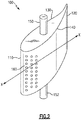
- FIG. 2 schematically illustrates an exemplary variable vane 100.
- the variable vane 100 includes a leading edge 110 and a trailing edge 120, with the leading edge 110 being the forward most edge relative to an expected direction of airflow through the turbine section 28 of the engine 20.
- the leading edge 110 is connected to the trailing edge 120 via a pressure side 130 and a suction side 140, with the sides 130, 140 forming an airfoil profile of the variable vane 100.
- Protruding radially outward from an outer portion of the vane, relative to a radius of the engine 20, is a first spindle 150.
- protruding radially inward from an inward portion of the vane 100 is a second spindle 152.
- Each of the spindles 150, 152 connect to an engine static structure and drive the position of the variable vane 100.
- an engine controller determines that the angle of attack of the vane 100 should be altered, the spindles 150, 152 are rotated, which causes a corresponding rotation of the vane 100.
- the vane 100 includes multiple internal cooling passages 170, 172 (illustrated in Figures 3A and 3B ), with at least a portion of the internal cooling passages being connected to the pressure side 130 and the suction side 140 via corresponding film cooling holes 160. While only illustrated at the leading edge 110 area of the vane 100, it is appreciated that the film cooling holes 160 can be distributed across the pressure side and the suction side of the vane 100.
- Figure 3 schematically illustrates a cross section of the vane 100 drawn along X-X in a first position ( Figure 3A ) and a second position ( Figure 3B ). Included is a first set of internal cooling passages 170, and a second set of internal cooling passages 172. At least one of the cooling passages 172 in the second set of cooling passages 172 is connected to the exterior surface of the vane 100 via the film cooling holes 160. While only illustrated as being connected to the forward most internal cooling passage 172 in the second set of cooling passages 172, it is appreciated that other internal cooling passages 170, 172 can be connected to the external surface via film cooling holes as well.
- the vane 100 is angled directly toward an expected fluid flow 102 through the turbine section 28. Due to the angling of the vane 100, the outlet of the film cooling holes 160 are generally perpendicular to, or near perpendicular to the fluid flow 102, and a relatively low pressure margin is required in order to ensure that cooling air flows out of the film cooling holes 160, rather than turbine air flowing into the film cooling holes 160. However, when rotated (as shown in Figure 3B ), the outlets of the film cooling holes 160 are more aligned with the expected direction of fluid flow 102. As a result of the new alignment, the backflow margin in the second position is increased.
- the first set of cooling passages 170 and the second set of cooling passages 172 are isolated from each other and provided distinct cooling fluid feeds. In some examples, this construction is achieved via the use of two distinct casting cores during the casting process. In alternative examples, the separation of the first set of cooling passages 170 and the second set of cooling passages can be achieved in alternative manners.
- Figure 4 schematically illustrates the vane 100 cut along cross section Y-Y (illustrated in Figure 3A ).
- Figure 5 schematically illustrates the vane 100 cut along cross section Z-Z (illustrated in Figure 3B ).
- air is provided through the spindles 150, 152, with the radially outward spindle 150 providing air 180 to the first set of cooling passages 170, and the radially inward spindle 152 providing cooling air to the second set of cooling passages 172.
- the leading edge 110 and pressure side 130 are cooled via air from the radially outward spindle 180, and the trailing edge 120 and suction side 140 are cooled with air 182 provided through the radially inward spindle 152.
- the cooling air provided to the second set of cooling passages 172 is provided through the radially inward spindle or through an airfoil
- the cooling air is first passed through the secondary flow stream of the turbine upstream of the vane 100.
- the cooling air can then be provided directly to the spindle 152.
- the air is piped around or passed through a rotor hub of a rotor adjacent to the vane 100 to provide the airflow 182 into the spindle 152, and thus into the internal cooling passages 172.
- variable turbine vane While described above with regards to the specific context of a variable turbine vane, one of skill in the art will appreciate that features of this disclosure can be incorporated into other flowpath components including fixed vanes and rotors with minimal modifications to the underlying structure.
Abstract
Description
- The present disclosure relates generally to cooling circuits for a gas turbine engine flowpath component.
- Gas turbine engines, such as those utilized in commercial and military aircraft, include a compressor section that compresses air, a combustor section in which the compressed air is mixed with a fuel and ignited, and a turbine section through which the resultant combustion products are expanded. The expansion of the combustion products drives the turbine section to rotate. As the turbine section is connected to the compressor section via a shaft, the rotation of the turbine section further drives the compressor section to rotate. In some examples, a fan is also connected to the shaft and is driven to rotate via rotation of the turbine as well.
- Some gas turbine engines include multiple compressor and turbine stages, each of which is defined by a pairing of flow directing rotors and vanes. In certain examples, one or more of the flowpath components within the stage can include cooling passages that expel air along the surface of the flowpath component to create a film cooling effect. Cooling air in such examples is typically provided from a flow inlet at a single end of the flowpath component.
- According to a first aspect of the present invention, there is provided a flowpath component for a gas turbine engine comprising a body having a leading edge and a trailing edge, a first exterior wall connecting the leading edge to the trailing edge and a second exterior wall connecting the leading edge to the trailing edge; at least one first internal cooling passage having a first inlet at a first end of the body; at least one second internal cooling passage having a second inlet at a second end of the body; and wherein the at least one first internal cooling passage is isolated from the at least one second internal cooling passage.
- In an embodiment of the above embodiment, the body is a variable vane having a first angle of attack in a first vane position and a second angle of attack in a second vane position.
- In an embodiment of any of the above embodiments, the body has an airfoil profile and is configured to have a first angle of attack in a first position and a second angle of attack in a second position.
- In an embodiment of any of the above embodiments, the first end of the body is a radially outward end relative to an engine in which the flowpath component is incorporated.
- In an embodiment of any of the above embodiments, the second end of the body is a radially inward end opposite the first end.
- In an embodiment of any of the above embodiments, the component comprises a plurality of cooling film holes connecting the at least one second internal cooling passage to an exterior edge of the flowpath body.
- In an embodiment of any of the above described embodiments, at least a portion of the at least one second internal cooling passage extends to the leading edge.
- In an embodiment of any of the above embodiments, the flowpath body is a first stage turbine vane.
- In an embodiment of any of the above embodiments, the flowpath body is a second or later stage turbine vane.
- In an embodiment of any of the above embodiments, the second inlet is connected to a feed through passage in an adjacent rotor hub.
- According to a second aspect of the present invention, there is provided a gas turbine engine comprising a compressor section having a plurality of compressor stages, each compressor stage in the plurality of compressor stages including a set of compressor rotors and a set of compressor vanes; a combustor section fluidly connected to the compressor section and including a combustor; a turbine section fluidly connected to the combustor section and including a plurality of turbine stages, each of the turbine stages in the plurality of turbine stages including a set of rotors and a set of turbine vanes; wherein at least one of the set of compressor vanes and the set of turbine vanes comprises a set of variable vanes each vane in the set of variable vanes having a body having a leading edge and a trailing edge, a first exterior wall connecting the leading edge to the trailing edge and a second exterior wall connecting the leading edge to the trailing edge, at least one first internal cooling passage having a first inlet at a first end of the body, at least one second internal cooling passage having a second inlet at a second end of the body, and wherein the at least one first internal cooling passage is isolated from the at least one second internal cooling passage.
- In an embodiment of any of the above embodiments, the body has an airfoil profile and is configured to have a first angle of attack in a first position and a second angle of attack in a second position.
- In an embodiment of any of the above embodiments, the first end of the body is a radially outward end relative to a radius of the engine and the second end of the body is a radially inward end opposite the first end.
- In an embodiment of any of the above embodiments, the set of variable vanes is a subset of vanes in a single stage, and wherein the set of variable vanes are alternated with a set of fixed vanes within the stage.
- In an embodiment of any of the above embodiments, the first inlet is disposed within a spindle.
- In an embodiment of any of the above embodiments the gas turbine engine also comprises a plurality of cooling film holes connecting the at least one second internal cooling passage to an exterior edge of the body.
- In an embodiment of any of the above embodiments, at least a portion of the at least one second internal cooling passage extends to the leading edge.
- In an embodiment of any of the above embodiments, the second inlet is connected to a feed through passage in an adjacent rotor hub.
- According to a third aspect of the present invention, there is provided a method for cooling a variable vane comprising providing a first cooling flow to a first set of internal cooling passages from a first cooling flow inlet; and providing a second cooling flow to a second set of internal cooling passages from a second cooling flow inlet, the second set of internal cooling passages being isolated from the first set of internal cooling passages.
- An embodiment of the above method comprises providing the first cooling flow to the first set of internal cooling passages, and comprises providing the first cooling flow through a radially outward spindle of the variable vane, wherein providing the second cooling flow to the second set of internal cooling passages comprises providing the second cooling flow through a radially inward spindle of the variable vane, and wherein the method further includes cooling a leading edge of the variable vane and a pressure side of the variable vane using the first cooling flow and cooling a trailing edge and the suction side of the variable vane using the second cooling flow.
- These and other features of the present invention can be best understood from the following specification and drawings, the following of which is a brief description.
-
-
Figure 1 illustrates a gas turbine engine according to an embodiment of the present invention. -
Figure 2 schematically illustrates an isometric view of a variable vane in the gas turbine engine ofFigure 1 . -
Figure 3 schematically illustrates an axially aligned cross section of the variable vane ofFigure 2 in a first position (Figure 3A ) and a second position (Figure 3B ). -
Figure 4 Schematically illustrates a first radial cross sectional view of the exemplary vane ofFigure 2 . -
Figure 5 schematically illustrates a second radial cross sectional view of the exemplary variable vane ofFigure 2 . -
Figure 1 schematically illustrates agas turbine engine 20. Thegas turbine engine 20 is disclosed herein as a two-spool turbofan that generally incorporates afan section 22, acompressor section 24, acombustor section 26 and aturbine section 28. Thefan section 22 drives air along a bypass flow path B in a bypass duct defined within ahousing 15 such as a fan case or nacelle, and also drives air along a core flow path C for compression and communication into thecombustor section 26 then expansion through theturbine section 28. Although depicted as a two-spool turbofan gas turbine engine in the disclosed non-limiting embodiment, it should be understood that the concepts described herein are not limited to use with two-spool turbofans as the teachings may be applied to other types of turbine engines including but not limited to three-spool architectures, turbofans with a direct driven fan, turbofans with a gear driven fan, and turbofans with multiple bypass flowpaths. - The
exemplary engine 20 generally includes alow speed spool 30 and ahigh speed spool 32 mounted for rotation about an engine central longitudinal axis A relative to an enginestatic structure 36 viaseveral bearing systems 38. It should be understood thatvarious bearing systems 38 at various locations may alternatively or additionally be provided, and the location ofbearing systems 38 may be varied as appropriate to the application. - The
low speed spool 30 generally includes an inner shaft 40 that interconnects, a first (or low)pressure compressor 44 and a first (or low)pressure turbine 46. The inner shaft 40 is connected to thefan 42 through a speed change mechanism, which in exemplarygas turbine engine 20 is illustrated as a gearedarchitecture 48 to drive afan 42 at a lower speed than thelow speed spool 30. Thehigh speed spool 32 includes anouter shaft 50 that interconnects a second (or high)pressure compressor 52 and a second (or high)pressure turbine 54. Acombustor 56 is arranged inexemplary gas turbine 20 between thehigh pressure compressor 52 and thehigh pressure turbine 54. Amid-turbine frame 57 of the enginestatic structure 36 may be arranged generally between thehigh pressure turbine 54 and thelow pressure turbine 46. Themid-turbine frame 57 further supports bearingsystems 38 in theturbine section 28. The inner shaft 40 and theouter shaft 50 are concentric and rotate viabearing systems 38 about the engine central longitudinal axis A which is collinear with their longitudinal axes. - The core airflow is compressed by the
low pressure compressor 44 then thehigh pressure compressor 52, mixed and burned with fuel in thecombustor 56, then expanded through thehigh pressure turbine 54 andlow pressure turbine 46. Themid-turbine frame 57 includesairfoils 59 which are in the core airflow path C. Theturbines low speed spool 30 andhigh speed spool 32 in response to the expansion. It will be appreciated that each of the positions of thefan section 22,compressor section 24,combustor section 26,turbine section 28, and fandrive gear system 48 may be varied. For example,gear system 48 may be located aft of the low pressure compressor, or aft of thecombustor section 26 or even aft ofturbine section 28, andfan 42 may be positioned forward or aft of the location ofgear system 48. - The
engine 20 in one example is a high-bypass geared aircraft engine. In a further example, theengine 20 bypass ratio is greater than about 6:1, with an example embodiment being greater than about 10:1, the gearedarchitecture 48 is an epicyclic gear train, such as a planetary gear system or other gear system, with a gear reduction ratio of greater than about 2.3:1 and thelow pressure turbine 46 has a pressure ratio that is greater than about 5:1. In one disclosed embodiment, theengine 20 bypass ratio is greater than about 10:1, the fan diameter is significantly larger than that of thelow pressure compressor 44, and thelow pressure turbine 46 has a pressure ratio that is greater than about five 5:1. Thelow pressure turbine 46 pressure ratio is pressure measured prior to the inlet oflow pressure turbine 46 as related to the pressure at the outlet of thelow pressure turbine 46 prior to an exhaust nozzle. The gearedarchitecture 48 may be an epicycle gear train, such as a planetary gear system or other gear system, with a gear reduction ratio of greater than about 2.3:1 and less than about 5:1. It should be understood, however, that the above parameters are only exemplary of one embodiment of a geared architecture engine and that the present invention is applicable to other gas turbine engines including but not limited to direct drive turbofans. - A significant amount of thrust is provided by the bypass flow B due to the high bypass ratio. The
fan section 22 of theengine 20 is designed for a particular flight condition -- typically cruise at about 0.8 Mach and about 35,000 feet (10,668 meters). The flight condition of 0.8 Mach and 35,000 ft (10,668 meters), with the engine at its best fuel consumption - also known as "bucket cruise Thrust Specific Fuel Consumption ('TSFC')" - is the industry standard parameter of lbm of fuel being burned divided by lbf of thrust the engine produces at that minimum point. "Low fan pressure ratio" is the pressure ratio across the fan blade alone, without a Fan Exit Guide Vane ("FEGV") system. The low fan pressure ratio as disclosed herein according to one non-limiting embodiment is less than about 1.45:1. "Low corrected fan tip speed" is the actual fan tip speed in ft/sec divided by an industry standard temperature correction of [(Tram °R) / (518.7 °R)]0.5 (where °R = K x 9/5). The "Low corrected fan tip speed" as disclosed herein according to one non-limiting embodiment is less than about 1150 ft / second (350.5 meters/second). - Within the
turbine section 28 are multiple stages, each of which includes a set of rotors circumferentially disposed about an axis defined by theengine 20 and fixed to a corresponding rotating shaft. Each set of rotors is paired with a corresponding set of vanes, with the vanes being connected to an engine static structure. In some examples, such as the examples illustrated inFigures 2-6 and described below, the vanes in one or more stages can be configured to transition between two or more angles of attack, relative to airflow through theturbine section 28. Such vanes are referred to as variable vanes due to the ability to vary their angle of attack. In some examples a stage can include all variable vanes. In alternative examples, a single stage can include alternating fixed and variable vanes. In other examples, alternative fixed/variable vane configurations can be incorporated in a single stage. - Due to the extreme levels of heat that turbine sections are exposed to, many or all of the vanes can include internal cooling passages that distribute cooling air through the vanes. The cooling air is then dispersed to an exterior surface of the vane through holes connecting one or more of the passages to the exterior surface of the vane to create a film cooling effect that protects the exterior of the vane from the extreme heat. One factor that is considered in the design of vanes, and other flowpath components including film cooling, is the back flow margin.
- To achieve the film cooling, pressure from the internal cooling passages to the external surface in the gaspath drives the cooler air from the internal passage through the film cooling passages in the wall of the flowpath component. The pressure ratio required to drive the air outward, rather than allow hot flowpath air into the flowpath component, is referred to as the backflow margin. When the flowpath components, such as the vanes, have variable angles of attack, altering the angle of attack alters the backflow margin of the film cooling holes, and the pressure of the air available to the film cooling holes from the internal cavities can limit the magnitude of variance in the angle of attack that can be efficiently achieved.
- With continued reference to
Figure 1 ,Figure 2 schematically illustrates an exemplaryvariable vane 100. Thevariable vane 100 includes aleading edge 110 and a trailingedge 120, with theleading edge 110 being the forward most edge relative to an expected direction of airflow through theturbine section 28 of theengine 20. Theleading edge 110 is connected to the trailingedge 120 via apressure side 130 and asuction side 140, with thesides variable vane 100. Protruding radially outward from an outer portion of the vane, relative to a radius of theengine 20, is afirst spindle 150. Similarly, protruding radially inward from an inward portion of thevane 100 is asecond spindle 152. Each of thespindles variable vane 100. During operation, when an engine controller determines that the angle of attack of thevane 100 should be altered, thespindles vane 100. - Included within the
vane 100 are multipleinternal cooling passages 170, 172 (illustrated inFigures 3A and 3B ), with at least a portion of the internal cooling passages being connected to thepressure side 130 and thesuction side 140 via corresponding film cooling holes 160. While only illustrated at theleading edge 110 area of thevane 100, it is appreciated that the film cooling holes 160 can be distributed across the pressure side and the suction side of thevane 100. - With continued reference to
Figure 2 ,Figure 3 schematically illustrates a cross section of thevane 100 drawn along X-X in a first position (Figure 3A ) and a second position (Figure 3B ). Included is a first set ofinternal cooling passages 170, and a second set ofinternal cooling passages 172. At least one of thecooling passages 172 in the second set of coolingpassages 172 is connected to the exterior surface of thevane 100 via the film cooling holes 160. While only illustrated as being connected to the forward mostinternal cooling passage 172 in the second set of coolingpassages 172, it is appreciated that otherinternal cooling passages - In the illustrated example of
Figure 3A , thevane 100 is angled directly toward an expectedfluid flow 102 through theturbine section 28. Due to the angling of thevane 100, the outlet of the film cooling holes 160 are generally perpendicular to, or near perpendicular to thefluid flow 102, and a relatively low pressure margin is required in order to ensure that cooling air flows out of the film cooling holes 160, rather than turbine air flowing into the film cooling holes 160. However, when rotated (as shown inFigure 3B ), the outlets of the film cooling holes 160 are more aligned with the expected direction offluid flow 102. As a result of the new alignment, the backflow margin in the second position is increased. - In order to provide sufficient backflow margin to the second set of cooling
passages 172 to prevent backflow through the film cooling holes 160, the first set of coolingpassages 170 and the second set of coolingpassages 172 are isolated from each other and provided distinct cooling fluid feeds. In some examples, this construction is achieved via the use of two distinct casting cores during the casting process. In alternative examples, the separation of the first set of coolingpassages 170 and the second set of cooling passages can be achieved in alternative manners. - With continued reference to
Figures 3A and 3B ,Figure 4 schematically illustrates thevane 100 cut along cross section Y-Y (illustrated inFigure 3A ). Similarly,Figure 5 schematically illustrates thevane 100 cut along cross section Z-Z (illustrated inFigure 3B ). In order to provide each set ofinternal cooling passages spindles outward spindle 150 providingair 180 to the first set of coolingpassages 170, and the radiallyinward spindle 152 providing cooling air to the second set of coolingpassages 172. Put another way, theleading edge 110 andpressure side 130 are cooled via air from the radiallyoutward spindle 180, and the trailingedge 120 andsuction side 140 are cooled withair 182 provided through the radiallyinward spindle 152. - As the cooling air provided to the second set of cooling
passages 172 is provided through the radially inward spindle or through an airfoil, the cooling air is first passed through the secondary flow stream of the turbine upstream of thevane 100. In examples where thevane 100 is the first stage of the turbine section, the cooling air can then be provided directly to thespindle 152. In examples where thevane 100 is the second or later stage of theturbine section 28, the air is piped around or passed through a rotor hub of a rotor adjacent to thevane 100 to provide theairflow 182 into thespindle 152, and thus into theinternal cooling passages 172. - While described above with regards to the specific context of a variable turbine vane, one of skill in the art will appreciate that features of this disclosure can be incorporated into other flowpath components including fixed vanes and rotors with minimal modifications to the underlying structure.
- It is further understood that any of the above described concepts can be used alone or in combination with any or all of the other above described concepts. Although an embodiment of this invention has been disclosed, a worker of ordinary skill in this art would recognize that certain modifications would come within the scope of this invention. For that reason, the following claims should be studied to determine the true scope and content of this invention.
Claims (14)
- A flowpath component for a gas turbine engine (20) comprising:a body having a leading edge (110) and a trailing edge (120), a first exterior wall (130) connecting the leading edge (110) to the trailing edge (120) and a second exterior wall (140) connecting the leading edge (110) to the trailing edge (120);at least one first internal cooling passage (170) having a first inlet at a first end of the body;at least one second internal cooling passage (172) having a second inlet at a second end of the body; andwherein the at least one first internal cooling passage (170) is isolated from the at least one second internal cooling passage (172).
- The flowpath component of claim 1, wherein the body is a variable vane (100) having a first angle of attack in a first vane position and a second angle of attack in a second vane position.
- The flowpath component of claim 1 or 2, wherein the flowpath body is a first stage turbine vane, a second stage turbine vane, or later stage turbine vane.
- A gas turbine engine (20) comprising:a compressor section (24) having a plurality of compressor stages, each compressor stage in the plurality of compressor stages including a set of compressor rotors and a set of compressor vanes;a combustor section (26) fluidly connected to the compressor section (24) and including a combustor (56);a turbine section (28) fluidly connected to the combustor section (26) and including a plurality of turbine stages, each of the turbine stages in the plurality of turbine stages including a set of rotors and a set of turbine vanes;wherein at least one of the set of compressor vanes and the set of turbine vanes comprises a set of variable vanes (100) each vane (100) in the set of variable vanes (100) having a body having a leading edge (110) and a trailing edge (120), a first exterior wall connecting the leading edge (110) to the trailing edge (120) and a second exterior wall connecting the leading edge (110) to the trailing edge (120), at least one first internal cooling passage (170) having a first inlet at a first end of the body, at least one second internal cooling passage (172) having a second inlet at a second end of the body, and wherein the at least one first internal cooling passage (170) is isolated from the at least one second internal cooling passage (172).
- The gas turbine engine (20) of claim 4, wherein the set of variable vanes (100) is a subset of vanes in a single stage, and wherein the set of variable vanes (100) are alternated with a set of fixed vanes within the stage.
- The gas turbine engine (20) of claim 4 or 5, wherein the first inlet is disposed within a spindle (150).
- The flowpath component of any of claims 1 to 3 or the gas turbine engine (20) of any of claims 4 to 6, wherein the body has an airfoil profile and is configured to have a first angle of attack in a first position and a second angle of attack in a second position.
- The flowpath component of any of claims 1 to 3 or 7 or the gas turbine engine (20) of any of claims 4 to 7, wherein the first end of the body is a radially outward end relative to an engine (20) in which the flowpath component is incorporated.
- The flowpath component of any of claims 1 to 3, 7 or 8 or the gas turbine engine (20) of any of claims 4 to 8, wherein the second end of the body is a radially inward end opposite the first end.
- The flowpath component of any of claims 1 to 3 or 7 to 9 or the gas turbine engine (20) of any of claims 4 to 9, further comprising a plurality of cooling film (160) holes connecting the at least one second internal cooling passage (172) to an exterior edge of the flowpath body or body.
- The flowpath component of any of claims 1 to 3 or 7 to 10 or the gas turbine engine (20) of any of claims 4 to 10, wherein at least a portion of the at least one second internal cooling passage (172) extends to the leading edge (110).
- The flowpath component of any of claims 1 to 3 or 7 to 11 or the gas turbine engine (20) of any of claims 4 to 11, wherein the second inlet is connected to a feed through passage in an adjacent rotor hub.
- A method for cooling a variable vane (100) comprising:providing a first cooling flow to a first set of internal cooling passages (170) from a first cooling flow inlet; andproviding a second cooling flow to a second set of internal cooling passages (172) from a second cooling flow inlet, the second set of internal cooling passages (172) being isolated from the first set of internal cooling passages (170).
- The method of claim 13, wherein providing the first cooling flow to the first set of internal cooling passages (170) comprises providing the first cooling flow through a radially outward spindle (150) of the variable vane (100), wherein providing the second cooling flow to the second set of internal cooling passages (172) comprises providing the second cooling flow through a radially inward spindle (152) of the variable vane (100), and wherein the method further includes cooling a leading edge (110) of the variable vane (100) and a pressure side (130) of the variable vane (100) using the first cooling flow and cooling a trailing edge (120) and the suction side (140) of the variable vane (100) using the second cooling flow.
Applications Claiming Priority (1)
| Application Number | Priority Date | Filing Date | Title |
|---|---|---|---|
| US16/587,684 US11591915B2 (en) | 2019-09-30 | 2019-09-30 | Multi-flow cooling circuit for gas turbine engine flowpath component |
Publications (1)
| Publication Number | Publication Date |
|---|---|
| EP3798417A1 true EP3798417A1 (en) | 2021-03-31 |
Family
ID=72560372
Family Applications (1)
| Application Number | Title | Priority Date | Filing Date |
|---|---|---|---|
| EP20196540.7A Pending EP3798417A1 (en) | 2019-09-30 | 2020-09-16 | Multi-flow cooling circuit for gas turbine engine flowpath component |
Country Status (2)
| Country | Link |
|---|---|
| US (1) | US11591915B2 (en) |
| EP (1) | EP3798417A1 (en) |
Families Citing this family (1)
| Publication number | Priority date | Publication date | Assignee | Title |
|---|---|---|---|---|
| US20230222702A1 (en) * | 2022-01-11 | 2023-07-13 | Raytheon Technologies Corporation | Aircraft communication visualization |
Citations (4)
| Publication number | Priority date | Publication date | Assignee | Title |
|---|---|---|---|---|
| US20160061112A1 (en) * | 2014-08-28 | 2016-03-03 | United Technologies Corporation | Shielded pass through passage in a gas turbine engine structure |
| US20170248021A1 (en) * | 2016-02-25 | 2017-08-31 | United Technologies Corporation | Airfoil having pedestals in trailing edge cavity |
| US20180135459A1 (en) * | 2016-11-17 | 2018-05-17 | United Technologies Corporation | Airfoil with sealed baffle |
| EP3498979A1 (en) * | 2017-12-18 | 2019-06-19 | United Technologies Corporation | Cooled airfoil |
Family Cites Families (11)
| Publication number | Priority date | Publication date | Assignee | Title |
|---|---|---|---|---|
| US4798515A (en) * | 1986-05-19 | 1989-01-17 | The United States Of America As Represented By The Secretary Of The Air Force | Variable nozzle area turbine vane cooling |
| DE10009655C1 (en) * | 2000-02-29 | 2001-05-23 | Mtu Aero Engines Gmbh | Air cooling system for the paddles of a high pressure gas turbine has flow chambers at each paddle for the leading and trailing edges and the center profile with a heat exchanger to cool the air flow to the paddle edges |
| EP1249578B1 (en) * | 2001-04-11 | 2006-10-11 | Siemens Aktiengesellschaft | Cooling of a gas turbine |
| US8007229B2 (en) * | 2007-05-24 | 2011-08-30 | United Technologies Corporation | Variable area turbine vane arrangement |
| US9140188B2 (en) * | 2011-10-25 | 2015-09-22 | United Technologies Corporation | Gas turbine engine with intercooling turbine section |
| US10287900B2 (en) * | 2013-10-21 | 2019-05-14 | United Technologies Corporation | Incident tolerant turbine vane cooling |
| EP3068977B1 (en) | 2013-11-14 | 2019-07-10 | United Technologies Corporation | Gas turbine vane assembly comprising a rotatable vane with protrusions on the pressure or suction side |
| FR3051219B1 (en) | 2016-05-12 | 2019-06-07 | Safran Aircraft Engines | TURBOMACHINE TURBINE, SUCH AS A TURBOREACTOR OR AIRCRAFT TURBOPROPOWER |
| US10502070B2 (en) * | 2016-11-17 | 2019-12-10 | United Technologies Corporation | Airfoil with laterally insertable baffle |
| US10605088B2 (en) * | 2016-11-17 | 2020-03-31 | United Technologies Corporation | Airfoil endwall with partial integral airfoil wall |
| JP7096058B2 (en) * | 2018-04-18 | 2022-07-05 | 三菱重工業株式会社 | Gas turbine system |
-
2019
- 2019-09-30 US US16/587,684 patent/US11591915B2/en active Active
-
2020
- 2020-09-16 EP EP20196540.7A patent/EP3798417A1/en active Pending
Patent Citations (4)
| Publication number | Priority date | Publication date | Assignee | Title |
|---|---|---|---|---|
| US20160061112A1 (en) * | 2014-08-28 | 2016-03-03 | United Technologies Corporation | Shielded pass through passage in a gas turbine engine structure |
| US20170248021A1 (en) * | 2016-02-25 | 2017-08-31 | United Technologies Corporation | Airfoil having pedestals in trailing edge cavity |
| US20180135459A1 (en) * | 2016-11-17 | 2018-05-17 | United Technologies Corporation | Airfoil with sealed baffle |
| EP3498979A1 (en) * | 2017-12-18 | 2019-06-19 | United Technologies Corporation | Cooled airfoil |
Also Published As
| Publication number | Publication date |
|---|---|
| US20210095596A1 (en) | 2021-04-01 |
| US11591915B2 (en) | 2023-02-28 |
Similar Documents
| Publication | Publication Date | Title |
|---|---|---|
| US11725670B2 (en) | Compressor flowpath | |
| EP2975213B1 (en) | Gas turbine engine with vaneless transition duct | |
| EP2994627B1 (en) | Diffuser case strut for a turbine engine | |
| US11143039B2 (en) | Turbine engine component including an axially aligned skin core passage interrupted by a pedestal | |
| EP3054138B1 (en) | Turbo-compressor with geared turbofan | |
| US10107122B2 (en) | Variable vane overlap shroud | |
| US20190203602A1 (en) | Doublet vane assembly for a gas turbine engine | |
| EP2935804B1 (en) | Gas turbine engine inner case including non-symmetrical bleed slots | |
| EP3034793B1 (en) | Gas turbine engine component with increased cooling capacity | |
| EP3112596A1 (en) | Gas turbine engine airfoil with bi-axial skin cooling passage and corresponding gas turbine engine | |
| US20170002659A1 (en) | Tip shrouded high aspect ratio compressor stage | |
| US20140219813A1 (en) | Gas turbine engine serpentine cooling passage | |
| EP3822459A1 (en) | Blade outer air seal including cooling trench | |
| EP3798417A1 (en) | Multi-flow cooling circuit for gas turbine engine flowpath component | |
| EP3693544A1 (en) | Gas turbine tangential on board injector with a full sweeping nozzle | |
| EP2961964B1 (en) | Gas turbine engine component and corresponding method of manufacturing an aperture | |
| EP3450697A1 (en) | Vane cluster and corresponding gas turbine engine | |
| EP3832071B1 (en) | Gas turbine engine flowpath component including vectored cooling flow holes | |
| EP2977557A1 (en) | Cooled airfoil structure corresponding cooling method | |
| US10975702B2 (en) | Platform cooling arrangement for a gas turbine engine | |
| EP3045658A1 (en) | Gas turbine engine rotor | |
| EP3067520A1 (en) | Gas powered turbine component including serpentine cooling |
Legal Events
| Date | Code | Title | Description |
|---|---|---|---|
| PUAI | Public reference made under article 153(3) epc to a published international application that has entered the european phase |
Free format text: ORIGINAL CODE: 0009012 |
|
| STAA | Information on the status of an ep patent application or granted ep patent |
Free format text: STATUS: THE APPLICATION HAS BEEN PUBLISHED |
|
| AK | Designated contracting states |
Kind code of ref document: A1 Designated state(s): AL AT BE BG CH CY CZ DE DK EE ES FI FR GB GR HR HU IE IS IT LI LT LU LV MC MK MT NL NO PL PT RO RS SE SI SK SM TR |
|
| AX | Request for extension of the european patent |
Extension state: BA ME |
|
| STAA | Information on the status of an ep patent application or granted ep patent |
Free format text: STATUS: REQUEST FOR EXAMINATION WAS MADE |
|
| 17P | Request for examination filed |
Effective date: 20210930 |
|
| RBV | Designated contracting states (corrected) |
Designated state(s): AL AT BE BG CH CY CZ DE DK EE ES FI FR GB GR HR HU IE IS IT LI LT LU LV MC MK MT NL NO PL PT RO RS SE SI SK SM TR |
|
| STAA | Information on the status of an ep patent application or granted ep patent |
Free format text: STATUS: EXAMINATION IS IN PROGRESS |
|
| 17Q | First examination report despatched |
Effective date: 20221202 |
|
| RAP3 | Party data changed (applicant data changed or rights of an application transferred) |
Owner name: RTX CORPORATION |