EP3798372A1 - Measuring apparatus - Google Patents
Measuring apparatus Download PDFInfo
- Publication number
- EP3798372A1 EP3798372A1 EP20192379.4A EP20192379A EP3798372A1 EP 3798372 A1 EP3798372 A1 EP 3798372A1 EP 20192379 A EP20192379 A EP 20192379A EP 3798372 A1 EP3798372 A1 EP 3798372A1
- Authority
- EP
- European Patent Office
- Prior art keywords
- measurement module
- measuring apparatus
- excavation
- magnetometer
- accelerometer
- Prior art date
- Legal status (The legal status is an assumption and is not a legal conclusion. Google has not performed a legal analysis and makes no representation as to the accuracy of the status listed.)
- Granted
Links
Images


Classifications
-
- E—FIXED CONSTRUCTIONS
- E02—HYDRAULIC ENGINEERING; FOUNDATIONS; SOIL SHIFTING
- E02F—DREDGING; SOIL-SHIFTING
- E02F5/00—Dredgers or soil-shifting machines for special purposes
- E02F5/02—Dredgers or soil-shifting machines for special purposes for digging trenches or ditches
- E02F5/14—Component parts for trench excavators, e.g. indicating devices travelling gear chassis, supports, skids
-
- E—FIXED CONSTRUCTIONS
- E02—HYDRAULIC ENGINEERING; FOUNDATIONS; SOIL SHIFTING
- E02F—DREDGING; SOIL-SHIFTING
- E02F9/00—Component parts of dredgers or soil-shifting machines, not restricted to one of the kinds covered by groups E02F3/00 - E02F7/00
- E02F9/26—Indicating devices
- E02F9/264—Sensors and their calibration for indicating the position of the work tool
-
- G—PHYSICS
- G01—MEASURING; TESTING
- G01C—MEASURING DISTANCES, LEVELS OR BEARINGS; SURVEYING; NAVIGATION; GYROSCOPIC INSTRUMENTS; PHOTOGRAMMETRY OR VIDEOGRAMMETRY
- G01C21/00—Navigation; Navigational instruments not provided for in groups G01C1/00 - G01C19/00
- G01C21/10—Navigation; Navigational instruments not provided for in groups G01C1/00 - G01C19/00 by using measurements of speed or acceleration
- G01C21/12—Navigation; Navigational instruments not provided for in groups G01C1/00 - G01C19/00 by using measurements of speed or acceleration executed aboard the object being navigated; Dead reckoning
- G01C21/16—Navigation; Navigational instruments not provided for in groups G01C1/00 - G01C19/00 by using measurements of speed or acceleration executed aboard the object being navigated; Dead reckoning by integrating acceleration or speed, i.e. inertial navigation
- G01C21/165—Navigation; Navigational instruments not provided for in groups G01C1/00 - G01C19/00 by using measurements of speed or acceleration executed aboard the object being navigated; Dead reckoning by integrating acceleration or speed, i.e. inertial navigation combined with non-inertial navigation instruments
-
- E—FIXED CONSTRUCTIONS
- E02—HYDRAULIC ENGINEERING; FOUNDATIONS; SOIL SHIFTING
- E02F—DREDGING; SOIL-SHIFTING
- E02F9/00—Component parts of dredgers or soil-shifting machines, not restricted to one of the kinds covered by groups E02F3/00 - E02F7/00
- E02F9/26—Indicating devices
- E02F9/264—Sensors and their calibration for indicating the position of the work tool
- E02F9/265—Sensors and their calibration for indicating the position of the work tool with follow-up actions (e.g. control signals sent to actuate the work tool)
-
- E—FIXED CONSTRUCTIONS
- E21—EARTH OR ROCK DRILLING; MINING
- E21B—EARTH OR ROCK DRILLING; OBTAINING OIL, GAS, WATER, SOLUBLE OR MELTABLE MATERIALS OR A SLURRY OF MINERALS FROM WELLS
- E21B47/00—Survey of boreholes or wells
- E21B47/02—Determining slope or direction
- E21B47/022—Determining slope or direction of the borehole, e.g. using geomagnetism
- E21B47/0228—Determining slope or direction of the borehole, e.g. using geomagnetism using electromagnetic energy or detectors therefor
-
- G—PHYSICS
- G01—MEASURING; TESTING
- G01C—MEASURING DISTANCES, LEVELS OR BEARINGS; SURVEYING; NAVIGATION; GYROSCOPIC INSTRUMENTS; PHOTOGRAMMETRY OR VIDEOGRAMMETRY
- G01C21/00—Navigation; Navigational instruments not provided for in groups G01C1/00 - G01C19/00
- G01C21/04—Navigation; Navigational instruments not provided for in groups G01C1/00 - G01C19/00 by terrestrial means
- G01C21/08—Navigation; Navigational instruments not provided for in groups G01C1/00 - G01C19/00 by terrestrial means involving use of the magnetic field of the earth
-
- G—PHYSICS
- G01—MEASURING; TESTING
- G01V—GEOPHYSICS; GRAVITATIONAL MEASUREMENTS; DETECTING MASSES OR OBJECTS; TAGS
- G01V3/00—Electric or magnetic prospecting or detecting; Measuring magnetic field characteristics of the earth, e.g. declination, deviation
- G01V3/18—Electric or magnetic prospecting or detecting; Measuring magnetic field characteristics of the earth, e.g. declination, deviation specially adapted for well-logging
- G01V3/26—Electric or magnetic prospecting or detecting; Measuring magnetic field characteristics of the earth, e.g. declination, deviation specially adapted for well-logging operating with magnetic or electric fields produced or modified either by the surrounding earth formation or by the detecting device
Definitions
- the present invention relates to a measuring apparatus that is disposed in an excavation section of an underground excavator and is used for measuring an excavation position.
- Patent Literature 1 As related art of a measuring apparatus that is disposed in an excavation section of an underground excavator, there are known a measuring apparatus that is described in International Publication No. WO2015/111713 (hereinafter referred to as Patent Literature 1) and a measuring apparatus that is described in Hiroshi Arita, Takazumi Yamada, Yusuke Inoue, "Development of Digital Directional Module", JAE Technical Report, No. 39, 2017.3., Internet ⁇ https://www.jae.com/corporate/rd/tech-report/39/> (hereinafter referred to as Non-patent Literature 1), for example. Both of the measuring apparatuses include a triaxial accelerometer, a triaxial magnetometer, and an information processor. Fig.
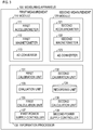
- Non-patent Literature 1 shows a processing flow illustrated in Fig. 5 of Patent Literature 1.
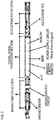
- Fig. 2 shows the configuration of the measuring apparatus illustrated in Fig. 1 of Non-patent Literature 1.
- measurement is performed every time excavation for one rod is ended. That is, a position of a front end of the excavation section is obtained during suspension of excavation.
- Non-patent Literature 1 describes that the measuring apparatus is capable of performing measurement not only during suspension of excavation but also during excavation.
- Non-patent Literature 1 describes that "vibration" and "rotation" generated by excavation are simultaneously applied to the whole of an underground excavator in practical excavation environments and provides the description of a method for calculating an inclination angle and an azimuth angle while eliminating influences of "vibration” and "rotation”.
- state quantities such as an inclination angle and an azimuth angle are accurately calculated by employing an unscented Kalman filter having high resistance against disturbance and repeating an estimation process and a correction process for every time step.
- a state quantity at current time is estimated by applying a physical model, which is obtained in consideration of vibration and rotation of a tool in excavation, to a state quantity of one step before.
- correction is performed so that an influence of disturbance noise is minimized, by using data of the accelerometer and the magnetometer obtained at current time, with respect to an estimated value.
- Non-patent Literature 1 describes that measurement can be also performed during excavation, meaning that electric power is also consumed during excavation.
- An object of the present invention is to reduce power consumption of a measuring apparatus.
- a measuring apparatus is to be disposed in an excavation section of an underground excavator.
- the measuring apparatus includes a first measurement module, a second measurement module, and an information processor.
- the first measurement module includes a triaxial first accelerometer and a triaxial first magnetometer for performing highly-accurate measurement.
- the second measurement module includes a triaxial second accelerometer and a triaxial second magnetometer for performing measurement during excavation.
- the information processor controls the first measurement module and the second measurement module and obtains a position and a direction of the excavation section based on output data of the first measurement module or the second measurement module.
- the second accelerometer and the second magnetometer are MEMS sensors.
- a MEMS sensor consuming less power is used during excavation, being able to reduce power consumption of the measuring apparatus.
- Fig. 3 illustrates a functional configuration of a measuring apparatus according to the present invention.
- Fig. 4 illustrates a flow of processing for obtaining a position and an attitude of an excavation section based on output data of a first measurement module and evaluating calibration data for a second measurement module.
- Fig. 5 illustrates a flow of processing for obtaining a position and an attitude of the excavation section based on output data of the second measurement module.
- a measuring apparatus 100 is a measuring apparatus that is to be disposed in an excavation section of an underground excavator.
- the measuring apparatus 100 includes a first measurement module 110, a second measurement module 120, and an information processor 130.
- the measuring apparatus 100 may be configured to be supplied with power from a battery (not shown) disposed in an excavation section.
- the first measurement module 110 includes a triaxial first accelerometer 111, a triaxial first magnetometer 112, and an AD converter 113 for performing highly-accurate measurement.
- the first accelerometer 111 measures accelerations in predetermined X-, Y-, and Z-axis directions.
- the first magnetometer 112 measures terrestrial magnetism in the predetermined X-, Y-, and Z-axis directions.
- the AD converter 113 AD-converts output of the first accelerometer 111 and the first magnetometer 112 so as to obtain output data of digital signals.
- the AD converter 113 may be disposed in the outside of the first measurement module 110.
- highly-accurate measurement can be realized by using the accelerometer and the magnetometer which are described in Non-patent Literature 1.
- the accelerometer and the magnetometer described in Non-patent Literature 1 are kept to be also used during excavation, power consumption is increased, causing frequent exchange of a battery disposed in the excavation section.
- the accelerometer and the magnetometer described in Non-patent Literature 1 are capable of performing highly-accurate measurement, dynamic ranges are narrow. Consequently, if the measuring apparatus is strongly influenced by vibration, impact, and rotation generated by excavation, measurement values thereof may be disadvantageously saturated.
- the second measurement module 120 includes a triaxial second accelerometer 121, a triaxial second magnetometer 122, and an AD converter 123 for performing measurement during excavation.
- the second accelerometer 121 and the second magnetometer 122 are sensors of micro electro mechanical systems (MEMS) type.
- the second accelerometer 121 measures accelerations in predetermined X-, Y-, and Z-axis directions.
- the second magnetometer 122 measures terrestrial magnetism in the predetermined X-, Y-, and Z-axis directions.
- the AD converter 123 AD-converts output of the second accelerometer 121 and the second magnetometer 122 so as to obtain output data of digital signals.
- the AD converter 123 may be disposed in the outside of the second measurement module 120.
- the second measurement module 120 may include another sensor of the MEMS type as well as the second accelerometer 121 and the second magnetometer 122.
- the information processor 130 controls the first measurement module 110 and the second measurement module 120 and obtains a position and an attitude of the excavation section based on output data of the first measurement module 110 or the second measurement module 120.
- the information processor 130 includes a first calibration unit 131, a second calibration unit 132, an evaluation unit 133, a recording unit 134, a first calculation unit 135, a second calculation unit 136, and a first power supply controller 137, for example.
- the recording unit 134 preliminarily records calibration data for calibrating the first accelerometer 111, the first magnetometer 112, the second accelerometer 121, and the second magnetometer 122. Calibration data may be recorded in the recording unit 134 in a factory before shipping.
- the first accelerometer 111 measures accelerations in the predetermined X-, Y-, and Z-axis directions and the first magnetometer 112 measures terrestrial magnetism in the predetermined X-, Y-, and Z-axis directions (S110). Then, the measured results are digitalized and inputted into the information processor 130 as output data of the first measurement module 110.
- the second accelerometer 121 measures accelerations in the predetermined X-, Y-, and Z-axis directions and the second magnetometer 122 measures terrestrial magnetism in the predetermined X-, Y-, and Z-axis directions (S120). Then, the measured results are digitalized and inputted into the information processor 130 as output data of the second measurement module 120.
- the first calibration unit 131 calibrates the output data of the first measurement module 110 based on calibration data recorded in the recording unit 134 (S131).
- the second calibration unit 132 calibrates the output data of the second measurement module 120 based on calibration data recorded in the recording unit 134 (S1321).
- the first calibration unit 131 and the second calibration unit 132 may also acquire data related to surrounding conditions such as temperature data from a temperature sensor (not shown) or the like provided to the excavation section and may use the data for calibration.
- the evaluation unit 133 compares the output data of the first measurement module 110 calibrated in step S131 with the output data of the second measurement module 120 calibrated in step S1321 to obtain an error of the calibrated output data of the second measurement module 120 (S133). That is, the evaluation unit 133 evaluates the calibrated output data of the second measurement module 120. For example, an obtained error may be recorded in the recording unit 134 and correction may be performed in later-described processing for calibrating output data of the second measurement module 120 (S1322) or processing of calculation by the second calculation unit 136 (S136). In this case, the information processor 130 corrects an error of output data of the second measurement module 120 based on output data of the first measurement module 110.
- calibration data itself recorded in the recording unit 134 may be corrected based on an obtained error, for example.
- the information processor 130 corrects calibration data for the second measurement module 120, which is recorded in the recording unit 134, based on output data of the first measurement module 110.
- the first calculation unit 135 obtains a position and an attitude of the excavation section based on the output data of the first measurement module 110 calibrated in step S131 (S135). That is, the information processor 130 obtains a position and an attitude of the excavation section based on the output data of the first measurement module 110.
- calculation illustrated in Patent Literature 1 may be used, for example.
- the method which uses an unscented Kalman filter and is described in Non-patent Literature 1 may be employed, for example.
- the first measurement module 110 is capable of performing highly-accurate measurement, a dynamic range of acceleration is generally narrow. Accordingly, it is suitable to avoid the processing of Fig. 4 when the measuring apparatus is strongly influenced by vibration, impact, and rotation generated by excavation.
- the information processor 130 may also include a second power supply controller 138.
- the second power supply controller 138 may suspend power supply from the battery disposed in the excavation section to the second measurement module 120 so as to turn off power supply of the second measurement module 120 from end of the processing in step S120 to start of the next processing in step S120. This processing can stop power consumption in the second measurement module 120.
- the second measurement module 120 includes the MEMS type sensors, power consumption thereof is small. Accordingly, the second power supply controller 138 does not have to be provided.
- the first power supply controller 137 of the information processor 130 suspends power supply from the battery disposed in the excavation section to the first measurement module 110 so as to turn off power supply of the first measurement module 110 before the start of excavation. This processing can stop power consumption in the first measurement module 110.
- a flow of processing for obtaining a position and an attitude of the excavation section based on output data of the second measurement module 120 is next explained with reference to Fig. 5 .
- the second accelerometer 121 measures accelerations in the predetermined X-, Y-, and Z-axis directions and the second magnetometer 122 measures terrestrial magnetism in the predetermined X-, Y-, and Z-axis directions (S120). Then, the measured results are digitalized and inputted into the information processor 130 as output data of the second measurement module 120.
- the second calibration unit 132 calibrates the output data of the second measurement module 120 based on calibration data recorded in the recording unit 134 (S1322).
- the second calibration unit 132 may also acquire data related to surrounding conditions such as temperature data from a temperature sensor (not shown) or the like provided to the excavation section and may use the data for calibration. Further, when an error of the output data of the second measurement module 120 is recorded in the recording unit 134, correction of the error may be also performed in the calibration in step S1322.
- the second calculation unit 136 obtains a position and an attitude of the excavation section based on the output data of the second measurement module 120 calibrated in step S1322 (S136). That is, the information processor 130 obtains a position and an attitude of the excavation section based on the output data of the second measurement module 120.
- the method which uses an unscented Kalman filter and is described in Non-patent Literature 1 may be employed.
- the calibrated output data obtained in step S1322 may be corrected in the calculation.
- the second accelerometer 121 and the second magnetometer 122 of the second measurement module 120 are MEMS sensors, thereby consuming less power. Accordingly, power consumption during excavation can be reduced.
- Excavation suspension time is approximately 1 minute with respect to excavation time 30 to 60 minutes, in general, so that the whole power consumption can be reduced by lowering power consumption during the excavation.
- An exchange interval for a battery disposed in the excavation section can be accordingly prolonged.
- measurement accuracy of the second accelerometer 121 and the second magnetometer 122 of the second measurement module 120 is lower than that of the first accelerometer 111 and the first magnetometer 112 of the first measurement module 110, dynamic ranges can be widened. That is, the risk of saturation in measurement values is low even if the measuring apparatus 100 is influenced by vibration, impact, and rotation during excavation. Accordingly, a position and an attitude of the excavation section can be also grasped even during excavation.
Landscapes
- Engineering & Computer Science (AREA)
- Remote Sensing (AREA)
- Mining & Mineral Resources (AREA)
- Radar, Positioning & Navigation (AREA)
- Physics & Mathematics (AREA)
- General Engineering & Computer Science (AREA)
- Structural Engineering (AREA)
- Life Sciences & Earth Sciences (AREA)
- Geology (AREA)
- Civil Engineering (AREA)
- Environmental & Geological Engineering (AREA)
- General Life Sciences & Earth Sciences (AREA)
- General Physics & Mathematics (AREA)
- Automation & Control Theory (AREA)
- Mechanical Engineering (AREA)
- Electromagnetism (AREA)
- Geophysics (AREA)
- Fluid Mechanics (AREA)
- Geochemistry & Mineralogy (AREA)
- Excavating Of Shafts Or Tunnels (AREA)
- Geophysics And Detection Of Objects (AREA)
Abstract
Description
- The present invention relates to a measuring apparatus that is disposed in an excavation section of an underground excavator and is used for measuring an excavation position.
- As related art of a measuring apparatus that is disposed in an excavation section of an underground excavator, there are known a measuring apparatus that is described in International Publication No.
WO2015/111713 (hereinafter referred to as Patent Literature 1) and a measuring apparatus that is described in Hiroshi Arita, Takazumi Yamada, Yusuke Inoue, "Development of Digital Directional Module", JAE Technical Report, No. 39, 2017.3., Internet <https://www.jae.com/corporate/rd/tech-report/39/> (hereinafter referred to as Non-patent Literature 1), for example. Both of the measuring apparatuses include a triaxial accelerometer, a triaxial magnetometer, and an information processor.Fig. 1 shows a processing flow illustrated inFig. 5 ofPatent Literature 1.Fig. 2 shows the configuration of the measuring apparatus illustrated inFig. 1 ofNon-patent Literature 1. InPatent Literature 1, measurement is performed every time excavation for one rod is ended. That is, a position of a front end of the excavation section is obtained during suspension of excavation. On the other hand,Non-patent Literature 1 describes that the measuring apparatus is capable of performing measurement not only during suspension of excavation but also during excavation.Non-patent Literature 1 describes that "vibration" and "rotation" generated by excavation are simultaneously applied to the whole of an underground excavator in practical excavation environments and provides the description of a method for calculating an inclination angle and an azimuth angle while eliminating influences of "vibration" and "rotation". Specifically, state quantities such as an inclination angle and an azimuth angle are accurately calculated by employing an unscented Kalman filter having high resistance against disturbance and repeating an estimation process and a correction process for every time step. In the estimation process, a state quantity at current time is estimated by applying a physical model, which is obtained in consideration of vibration and rotation of a tool in excavation, to a state quantity of one step before. In the correction process, correction is performed so that an influence of disturbance noise is minimized, by using data of the accelerometer and the magnetometer obtained at current time, with respect to an estimated value. -
Non-patent Literature 1 describes that measurement can be also performed during excavation, meaning that electric power is also consumed during excavation. An object of the present invention is to reduce power consumption of a measuring apparatus. - A measuring apparatus according to the present invention is to be disposed in an excavation section of an underground excavator. The measuring apparatus according to the present invention includes a first measurement module, a second measurement module, and an information processor. The first measurement module includes a triaxial first accelerometer and a triaxial first magnetometer for performing highly-accurate measurement. The second measurement module includes a triaxial second accelerometer and a triaxial second magnetometer for performing measurement during excavation. The information processor controls the first measurement module and the second measurement module and obtains a position and a direction of the excavation section based on output data of the first measurement module or the second measurement module. Further, the second accelerometer and the second magnetometer are MEMS sensors.
- According to the measuring apparatus of the present invention, a MEMS sensor consuming less power is used during excavation, being able to reduce power consumption of the measuring apparatus.
-
-
Fig. 1 shows a measurement processing flow in suspension of excavation illustrated inFig. 5 ofPatent Literature 1. -
Fig. 2 shows the configuration of the measuring apparatus illustrated inFig. 1 ofNon-patent Literature 1. -
Fig. 3 illustrates a functional configuration of a measuring apparatus according to the present invention. -
Fig. 4 illustrates a flow of processing for obtaining a position and an attitude of an excavation section based on output data of a first measurement module and evaluating calibration data for a second measurement module. -
Fig. 5 illustrates a flow of processing for obtaining a position and an attitude of the excavation section based on output data of the second measurement module. -
Fig. 3 illustrates a functional configuration of a measuring apparatus according to the present invention.Fig. 4 illustrates a flow of processing for obtaining a position and an attitude of an excavation section based on output data of a first measurement module and evaluating calibration data for a second measurement module.Fig. 5 illustrates a flow of processing for obtaining a position and an attitude of the excavation section based on output data of the second measurement module. - A measuring apparatus 100 is a measuring apparatus that is to be disposed in an excavation section of an underground excavator. The measuring apparatus 100 includes a first measurement module 110, a
second measurement module 120, and aninformation processor 130. The measuring apparatus 100 may be configured to be supplied with power from a battery (not shown) disposed in an excavation section. The first measurement module 110 includes a triaxialfirst accelerometer 111, a triaxialfirst magnetometer 112, and anAD converter 113 for performing highly-accurate measurement. Thefirst accelerometer 111 measures accelerations in predetermined X-, Y-, and Z-axis directions. Thefirst magnetometer 112 measures terrestrial magnetism in the predetermined X-, Y-, and Z-axis directions. TheAD converter 113 AD-converts output of thefirst accelerometer 111 and thefirst magnetometer 112 so as to obtain output data of digital signals. Here, theAD converter 113 may be disposed in the outside of the first measurement module 110. Specifically, highly-accurate measurement can be realized by using the accelerometer and the magnetometer which are described in Non-patentLiterature 1. However, if the accelerometer and the magnetometer described inNon-patent Literature 1 are kept to be also used during excavation, power consumption is increased, causing frequent exchange of a battery disposed in the excavation section. Further, though the accelerometer and the magnetometer described inNon-patent Literature 1 are capable of performing highly-accurate measurement, dynamic ranges are narrow. Consequently, if the measuring apparatus is strongly influenced by vibration, impact, and rotation generated by excavation, measurement values thereof may be disadvantageously saturated. - The
second measurement module 120 includes a triaxialsecond accelerometer 121, a triaxialsecond magnetometer 122, and anAD converter 123 for performing measurement during excavation. Thesecond accelerometer 121 and thesecond magnetometer 122 are sensors of micro electro mechanical systems (MEMS) type. Thesecond accelerometer 121 measures accelerations in predetermined X-, Y-, and Z-axis directions. Thesecond magnetometer 122 measures terrestrial magnetism in the predetermined X-, Y-, and Z-axis directions. TheAD converter 123 AD-converts output of thesecond accelerometer 121 and thesecond magnetometer 122 so as to obtain output data of digital signals. Here, theAD converter 123 may be disposed in the outside of thesecond measurement module 120. Further, thesecond measurement module 120 may include another sensor of the MEMS type as well as thesecond accelerometer 121 and thesecond magnetometer 122. - The
information processor 130 controls the first measurement module 110 and thesecond measurement module 120 and obtains a position and an attitude of the excavation section based on output data of the first measurement module 110 or thesecond measurement module 120. Theinformation processor 130 includes afirst calibration unit 131, asecond calibration unit 132, anevaluation unit 133, arecording unit 134, afirst calculation unit 135, asecond calculation unit 136, and a firstpower supply controller 137, for example. Therecording unit 134 preliminarily records calibration data for calibrating thefirst accelerometer 111, thefirst magnetometer 112, thesecond accelerometer 121, and thesecond magnetometer 122. Calibration data may be recorded in therecording unit 134 in a factory before shipping. - Referring to
Fig. 4 , a flow of processing for obtaining a position and an attitude of the excavation section based on output data of the first measurement module 110 and evaluating calibration data for thesecond measurement module 120 is first explained. Thefirst accelerometer 111 measures accelerations in the predetermined X-, Y-, and Z-axis directions and thefirst magnetometer 112 measures terrestrial magnetism in the predetermined X-, Y-, and Z-axis directions (S110). Then, the measured results are digitalized and inputted into theinformation processor 130 as output data of the first measurement module 110. Thesecond accelerometer 121 measures accelerations in the predetermined X-, Y-, and Z-axis directions and thesecond magnetometer 122 measures terrestrial magnetism in the predetermined X-, Y-, and Z-axis directions (S120). Then, the measured results are digitalized and inputted into theinformation processor 130 as output data of thesecond measurement module 120. - The
first calibration unit 131 calibrates the output data of the first measurement module 110 based on calibration data recorded in the recording unit 134 (S131). Thesecond calibration unit 132 calibrates the output data of thesecond measurement module 120 based on calibration data recorded in the recording unit 134 (S1321). Here, thefirst calibration unit 131 and thesecond calibration unit 132 may also acquire data related to surrounding conditions such as temperature data from a temperature sensor (not shown) or the like provided to the excavation section and may use the data for calibration. - The
evaluation unit 133 compares the output data of the first measurement module 110 calibrated in step S131 with the output data of thesecond measurement module 120 calibrated in step S1321 to obtain an error of the calibrated output data of the second measurement module 120 (S133). That is, theevaluation unit 133 evaluates the calibrated output data of thesecond measurement module 120. For example, an obtained error may be recorded in therecording unit 134 and correction may be performed in later-described processing for calibrating output data of the second measurement module 120 (S1322) or processing of calculation by the second calculation unit 136 (S136). In this case, theinformation processor 130 corrects an error of output data of thesecond measurement module 120 based on output data of the first measurement module 110. Alternatively, calibration data itself recorded in therecording unit 134 may be corrected based on an obtained error, for example. In this case, theinformation processor 130 corrects calibration data for thesecond measurement module 120, which is recorded in therecording unit 134, based on output data of the first measurement module 110. - The
first calculation unit 135 obtains a position and an attitude of the excavation section based on the output data of the first measurement module 110 calibrated in step S131 (S135). That is, theinformation processor 130 obtains a position and an attitude of the excavation section based on the output data of the first measurement module 110. When the processing illustrated inFig. 4 is performed during suspension of excavation, calculation illustrated inPatent Literature 1 may be used, for example. When the processing illustrated inFig. 4 is performed during excavation, the method which uses an unscented Kalman filter and is described inNon-patent Literature 1 may be employed, for example. However, since the first measurement module 110 is capable of performing highly-accurate measurement, a dynamic range of acceleration is generally narrow. Accordingly, it is suitable to avoid the processing ofFig. 4 when the measuring apparatus is strongly influenced by vibration, impact, and rotation generated by excavation. - Here, the
information processor 130 may also include a secondpower supply controller 138. For example, the secondpower supply controller 138 may suspend power supply from the battery disposed in the excavation section to thesecond measurement module 120 so as to turn off power supply of thesecond measurement module 120 from end of the processing in step S120 to start of the next processing in step S120. This processing can stop power consumption in thesecond measurement module 120. However, since thesecond measurement module 120 includes the MEMS type sensors, power consumption thereof is small. Accordingly, the secondpower supply controller 138 does not have to be provided. - A processing flow during excavation is now explained. The first
power supply controller 137 of theinformation processor 130 suspends power supply from the battery disposed in the excavation section to the first measurement module 110 so as to turn off power supply of the first measurement module 110 before the start of excavation. This processing can stop power consumption in the first measurement module 110. A flow of processing for obtaining a position and an attitude of the excavation section based on output data of thesecond measurement module 120 is next explained with reference toFig. 5 . Thesecond accelerometer 121 measures accelerations in the predetermined X-, Y-, and Z-axis directions and thesecond magnetometer 122 measures terrestrial magnetism in the predetermined X-, Y-, and Z-axis directions (S120). Then, the measured results are digitalized and inputted into theinformation processor 130 as output data of thesecond measurement module 120. - The
second calibration unit 132 calibrates the output data of thesecond measurement module 120 based on calibration data recorded in the recording unit 134 (S1322). Here, thesecond calibration unit 132 may also acquire data related to surrounding conditions such as temperature data from a temperature sensor (not shown) or the like provided to the excavation section and may use the data for calibration. Further, when an error of the output data of thesecond measurement module 120 is recorded in therecording unit 134, correction of the error may be also performed in the calibration in step S1322. - The
second calculation unit 136 obtains a position and an attitude of the excavation section based on the output data of thesecond measurement module 120 calibrated in step S1322 (S136). That is, theinformation processor 130 obtains a position and an attitude of the excavation section based on the output data of thesecond measurement module 120. In the calculation in step S136, the method which uses an unscented Kalman filter and is described inNon-patent Literature 1 may be employed. Further, when an error of the output data of thesecond measurement module 120 is recorded in therecording unit 134 and the error is not used in step S1322, the calibrated output data obtained in step S1322 may be corrected in the calculation. - The
second accelerometer 121 and thesecond magnetometer 122 of thesecond measurement module 120 are MEMS sensors, thereby consuming less power. Accordingly, power consumption during excavation can be reduced. Excavation suspension time is approximately 1 minute with respect to excavation time 30 to 60 minutes, in general, so that the whole power consumption can be reduced by lowering power consumption during the excavation. An exchange interval for a battery disposed in the excavation section can be accordingly prolonged. Further, though measurement accuracy of thesecond accelerometer 121 and thesecond magnetometer 122 of thesecond measurement module 120 is lower than that of thefirst accelerometer 111 and thefirst magnetometer 112 of the first measurement module 110, dynamic ranges can be widened. That is, the risk of saturation in measurement values is low even if the measuring apparatus 100 is influenced by vibration, impact, and rotation during excavation. Accordingly, a position and an attitude of the excavation section can be also grasped even during excavation.
Claims (5)
- A measuring apparatus (100) that is to be disposed in an excavation section of an underground excavator, the measuring apparatus comprising:a first measurement module (110) that includes a triaxial first accelerometer and a triaxial first magnetometer for performing highly-accurate measurement;a second measurement module (120) that includes a triaxial second accelerometer and a triaxial second magnetometer for performing measurement during excavation; andan information processor (130) that controls the first measurement module and the second measurement module and obtains a position and an attitude of the excavation section based on output data of the first measurement module or the second measurement module, whereinthe second accelerometer and the second magnetometer are MEMS sensors.
- The measuring apparatus according to Claim 1, wherein the information processor corrects an error of output data of the second measurement module based on output data of the first measurement module.
- The measuring apparatus according to Claim 1, wherein the information processor corrects calibration data for the second measurement module based on output data of the first measurement module.
- The measuring apparatus according to any one of Claims 1 to 3, wherein the information processor has a function of turning off power supply of the first measurement module.
- The measuring apparatus according to any one of Claims 1 to 4, wherein the measuring apparatus is supplied with power from a battery disposed in the excavation section of the underground excavator.
Applications Claiming Priority (2)
| Application Number | Priority Date | Filing Date | Title |
|---|---|---|---|
| US201962905595P | 2019-09-25 | 2019-09-25 | |
| US16/720,584 US11505915B2 (en) | 2019-09-25 | 2019-12-19 | Underground measuring apparatus |
Publications (2)
| Publication Number | Publication Date |
|---|---|
| EP3798372A1 true EP3798372A1 (en) | 2021-03-31 |
| EP3798372B1 EP3798372B1 (en) | 2022-11-02 |
Family
ID=72234702
Family Applications (1)
| Application Number | Title | Priority Date | Filing Date |
|---|---|---|---|
| EP20192379.4A Active EP3798372B1 (en) | 2019-09-25 | 2020-08-24 | Measuring apparatus |
Country Status (4)
| Country | Link |
|---|---|
| US (1) | US11505915B2 (en) |
| EP (1) | EP3798372B1 (en) |
| JP (1) | JP7401404B2 (en) |
| CN (1) | CN112556688B (en) |
Families Citing this family (2)
| Publication number | Priority date | Publication date | Assignee | Title |
|---|---|---|---|---|
| CN113080879A (en) * | 2021-05-06 | 2021-07-09 | 陕西福音假肢有限责任公司 | Circuit and method for continuously and dynamically measuring joint movement angle |
| CN113229804A (en) * | 2021-05-07 | 2021-08-10 | 陕西福音假肢有限责任公司 | Magnetic field data fusion circuit and method for joint mobility |
Citations (5)
| Publication number | Priority date | Publication date | Assignee | Title |
|---|---|---|---|---|
| US6315062B1 (en) * | 1999-09-24 | 2001-11-13 | Vermeer Manufacturing Company | Horizontal directional drilling machine employing inertial navigation control system and method |
| US20100100329A1 (en) * | 2008-10-22 | 2010-04-22 | Gyrodata, Incorporated | Downhole surveying utilizing multiple measurements |
| US20140318236A1 (en) * | 2013-04-24 | 2014-10-30 | Deere & Company | Liquid level detection system for a driveline component |
| WO2015111713A1 (en) | 2014-01-24 | 2015-07-30 | 国立大学法人九州大学 | Method for measuring ground excavation location, and ground excavation location measurement apparatus |
| US20160281331A1 (en) * | 2014-06-04 | 2016-09-29 | Komatsu Ltd. | Construction machine control system, construction machine, and construction machine control method |
Family Cites Families (12)
| Publication number | Priority date | Publication date | Assignee | Title |
|---|---|---|---|---|
| US3695112A (en) * | 1970-10-14 | 1972-10-03 | Clarence R Possell | Electrically operated temperature sensing assembly |
| US3987667A (en) * | 1975-06-09 | 1976-10-26 | The United States Of America As Represented By The Secretary Of The Interior | Self-contained instrument for measuring subterranean tunnel wall deflection |
| JPS616714U (en) * | 1984-06-18 | 1986-01-16 | 石福建設株式会社 | Light emitting target device used in small diameter pipe propulsion method |
| US5585726A (en) * | 1995-05-26 | 1996-12-17 | Utilx Corporation | Electronic guidance system and method for locating a discrete in-ground boring device |
| CN101532839B (en) * | 2009-04-09 | 2011-12-21 | 宋华 | Non-excavation measurement-while-drilling system based on inertia technology |
| CN102313543B (en) * | 2011-07-11 | 2013-07-17 | 上海大学 | Magnetic azimuth measuring system based on giant magneto-resistance sensor, measurement method and perpendicular compensation method |
| WO2016130804A1 (en) * | 2015-02-13 | 2016-08-18 | University Of Massachusetts | Wireless roadway sub-surface sensing system |
| US10550682B2 (en) * | 2015-10-22 | 2020-02-04 | Micropulse, Llc. | Programmable integrated measurement while drilling directional controller |
| CN206158732U (en) * | 2016-08-29 | 2017-05-10 | 中国科学院地质与地球物理研究所 | Nearly drill bit drilling tool gesture is along with boring measuring device |
| US10465509B2 (en) * | 2016-10-12 | 2019-11-05 | Baker Hughes, A Ge Company, Llc | Collocated multitone acoustic beam and electromagnetic flux leakage evaluation downhole |
| US10746758B2 (en) * | 2017-02-21 | 2020-08-18 | Hrl Laboratories, Llc | MEMS-based sensor suite |
| CN111655970B (en) * | 2017-12-04 | 2023-12-12 | Hrl实验室有限责任公司 | Continuous trajectory calculation for directional drilling |
-
2019
- 2019-12-19 US US16/720,584 patent/US11505915B2/en active Active
-
2020
- 2020-07-13 JP JP2020119621A patent/JP7401404B2/en active Active
- 2020-08-24 CN CN202010857814.2A patent/CN112556688B/en active Active
- 2020-08-24 EP EP20192379.4A patent/EP3798372B1/en active Active
Patent Citations (5)
| Publication number | Priority date | Publication date | Assignee | Title |
|---|---|---|---|---|
| US6315062B1 (en) * | 1999-09-24 | 2001-11-13 | Vermeer Manufacturing Company | Horizontal directional drilling machine employing inertial navigation control system and method |
| US20100100329A1 (en) * | 2008-10-22 | 2010-04-22 | Gyrodata, Incorporated | Downhole surveying utilizing multiple measurements |
| US20140318236A1 (en) * | 2013-04-24 | 2014-10-30 | Deere & Company | Liquid level detection system for a driveline component |
| WO2015111713A1 (en) | 2014-01-24 | 2015-07-30 | 国立大学法人九州大学 | Method for measuring ground excavation location, and ground excavation location measurement apparatus |
| US20160281331A1 (en) * | 2014-06-04 | 2016-09-29 | Komatsu Ltd. | Construction machine control system, construction machine, and construction machine control method |
Non-Patent Citations (1)
| Title |
|---|
| HIROSHI ARITATAKAZUMI YAMADAYUSUKE INOUE: "Development of Digital Directional Module", JAE TECHNICAL REPORT, March 2017 (2017-03-01), Retrieved from the Internet <URL:https://www.jae.com/corporate/rd/tech-report/39> |
Also Published As
| Publication number | Publication date |
|---|---|
| JP7401404B2 (en) | 2023-12-19 |
| JP2021051060A (en) | 2021-04-01 |
| CN112556688B (en) | 2024-05-24 |
| CN112556688A (en) | 2021-03-26 |
| US11505915B2 (en) | 2022-11-22 |
| EP3798372B1 (en) | 2022-11-02 |
| US20210087787A1 (en) | 2021-03-25 |
Similar Documents
| Publication | Publication Date | Title |
|---|---|---|
| US8374817B2 (en) | Auto-calibration of orientation sensing systems | |
| US10488431B2 (en) | Real-time accelerometer calibration | |
| EP1340042B1 (en) | Monitoring accuracy of an electronic compass | |
| EP1593931A4 (en) | Difference correcting method for posture determining instrument and motion measuring instrument | |
| CN103941309B (en) | Geomagnetic sensor calibration device and method thereof | |
| US7743519B2 (en) | Sensor module, method of correction therefor, and mobile object including the sensor module | |
| KR20110132527A (en) | Method and device for calibration of 3-axis magnetic field sensor | |
| WO2018025115A2 (en) | Method and system for calibrating components of an inertial measurement unit (imu) using scene-captured data | |
| JP2008076397A (en) | Compass sensor calibration method, apparatus and medium in consideration of magnetic environment, and azimuth measuring method, apparatus and medium using the same | |
| KR20110085495A (en) | Automatic calibration method during operation of sensor error and inertial navigation system using it | |
| CN110132271B (en) | Adaptive Kalman filtering attitude estimation algorithm | |
| CN119063764B (en) | A method for calibrating the direction of an inertial navigation system for mining | |
| CN106403952A (en) | Method for measuring combined attitudes of Satcom on the move with low cost | |
| US11505915B2 (en) | Underground measuring apparatus | |
| CN115655272A (en) | Temperature compensation method and system based on MEMS accelerometer zero offset and scale factor | |
| US11619683B2 (en) | Method for compensating for an influence of a magnetic interference source on a measurement of a magnetic field sensor in a device and a device | |
| CN111750846A (en) | Marine compass and dynamic calibration method thereof | |
| CN104819717B (en) | A kind of multi-rotor aerocraft attitude detecting method based on MEMS inertial sensor group | |
| CN110916577B (en) | Robot static state judgment method and device and robot | |
| CN101393023B (en) | Digital magnetic compass on-line demarcating method based on geomagnetic model | |
| CN102183232A (en) | Orientation sensor | |
| JP6859917B2 (en) | Angular velocity derivation device and angular velocity derivation method | |
| JP5190134B2 (en) | Angular velocity detection method and apparatus | |
| JP2013088162A (en) | State estimation apparatus | |
| US20230009227A1 (en) | Compensating a temperature-dependent quadrature-induced zero rate offset for a microelectromechanical gyroscope |
Legal Events
| Date | Code | Title | Description |
|---|---|---|---|
| PUAI | Public reference made under article 153(3) epc to a published international application that has entered the european phase |
Free format text: ORIGINAL CODE: 0009012 |
|
| STAA | Information on the status of an ep patent application or granted ep patent |
Free format text: STATUS: THE APPLICATION HAS BEEN PUBLISHED |
|
| AK | Designated contracting states |
Kind code of ref document: A1 Designated state(s): AL AT BE BG CH CY CZ DE DK EE ES FI FR GB GR HR HU IE IS IT LI LT LU LV MC MK MT NL NO PL PT RO RS SE SI SK SM TR |
|
| AX | Request for extension of the european patent |
Extension state: BA ME |
|
| STAA | Information on the status of an ep patent application or granted ep patent |
Free format text: STATUS: REQUEST FOR EXAMINATION WAS MADE |
|
| 17P | Request for examination filed |
Effective date: 20210902 |
|
| RBV | Designated contracting states (corrected) |
Designated state(s): AL AT BE BG CH CY CZ DE DK EE ES FI FR GB GR HR HU IE IS IT LI LT LU LV MC MK MT NL NO PL PT RO RS SE SI SK SM TR |
|
| STAA | Information on the status of an ep patent application or granted ep patent |
Free format text: STATUS: EXAMINATION IS IN PROGRESS |
|
| 17Q | First examination report despatched |
Effective date: 20211202 |
|
| GRAP | Despatch of communication of intention to grant a patent |
Free format text: ORIGINAL CODE: EPIDOSNIGR1 |
|
| STAA | Information on the status of an ep patent application or granted ep patent |
Free format text: STATUS: GRANT OF PATENT IS INTENDED |
|
| INTG | Intention to grant announced |
Effective date: 20220520 |
|
| GRAS | Grant fee paid |
Free format text: ORIGINAL CODE: EPIDOSNIGR3 |
|
| GRAA | (expected) grant |
Free format text: ORIGINAL CODE: 0009210 |
|
| STAA | Information on the status of an ep patent application or granted ep patent |
Free format text: STATUS: THE PATENT HAS BEEN GRANTED |
|
| RIN1 | Information on inventor provided before grant (corrected) |
Inventor name: ARITA, HIROSHI |
|
| AK | Designated contracting states |
Kind code of ref document: B1 Designated state(s): AL AT BE BG CH CY CZ DE DK EE ES FI FR GB GR HR HU IE IS IT LI LT LU LV MC MK MT NL NO PL PT RO RS SE SI SK SM TR |
|
| RAP3 | Party data changed (applicant data changed or rights of an application transferred) |
Owner name: JAPAN AVIATION ELECTRONICS INDUSTRY, LIMITED |
|
| REG | Reference to a national code |
Ref country code: GB Ref legal event code: FG4D |
|
| REG | Reference to a national code |
Ref country code: CH Ref legal event code: EP Ref country code: AT Ref legal event code: REF Ref document number: 1528840 Country of ref document: AT Kind code of ref document: T Effective date: 20221115 |
|
| REG | Reference to a national code |
Ref country code: DE Ref legal event code: R096 Ref document number: 602020006007 Country of ref document: DE |
|
| RAP4 | Party data changed (patent owner data changed or rights of a patent transferred) |
Owner name: JAPAN AVIATION ELECTRONICS INDUSTRY, LIMITED |
|
| REG | Reference to a national code |
Ref country code: IE Ref legal event code: FG4D |
|
| REG | Reference to a national code |
Ref country code: NL Ref legal event code: FP |
|
| REG | Reference to a national code |
Ref country code: NO Ref legal event code: T2 Effective date: 20221102 |
|
| REG | Reference to a national code |
Ref country code: LT Ref legal event code: MG9D |
|
| REG | Reference to a national code |
Ref country code: AT Ref legal event code: MK05 Ref document number: 1528840 Country of ref document: AT Kind code of ref document: T Effective date: 20221102 |
|
| PG25 | Lapsed in a contracting state [announced via postgrant information from national office to epo] |
Ref country code: SE Free format text: LAPSE BECAUSE OF FAILURE TO SUBMIT A TRANSLATION OF THE DESCRIPTION OR TO PAY THE FEE WITHIN THE PRESCRIBED TIME-LIMIT Effective date: 20221102 Ref country code: PT Free format text: LAPSE BECAUSE OF FAILURE TO SUBMIT A TRANSLATION OF THE DESCRIPTION OR TO PAY THE FEE WITHIN THE PRESCRIBED TIME-LIMIT Effective date: 20230302 Ref country code: LT Free format text: LAPSE BECAUSE OF FAILURE TO SUBMIT A TRANSLATION OF THE DESCRIPTION OR TO PAY THE FEE WITHIN THE PRESCRIBED TIME-LIMIT Effective date: 20221102 Ref country code: FI Free format text: LAPSE BECAUSE OF FAILURE TO SUBMIT A TRANSLATION OF THE DESCRIPTION OR TO PAY THE FEE WITHIN THE PRESCRIBED TIME-LIMIT Effective date: 20221102 Ref country code: ES Free format text: LAPSE BECAUSE OF FAILURE TO SUBMIT A TRANSLATION OF THE DESCRIPTION OR TO PAY THE FEE WITHIN THE PRESCRIBED TIME-LIMIT Effective date: 20221102 Ref country code: AT Free format text: LAPSE BECAUSE OF FAILURE TO SUBMIT A TRANSLATION OF THE DESCRIPTION OR TO PAY THE FEE WITHIN THE PRESCRIBED TIME-LIMIT Effective date: 20221102 |
|
| PG25 | Lapsed in a contracting state [announced via postgrant information from national office to epo] |
Ref country code: RS Free format text: LAPSE BECAUSE OF FAILURE TO SUBMIT A TRANSLATION OF THE DESCRIPTION OR TO PAY THE FEE WITHIN THE PRESCRIBED TIME-LIMIT Effective date: 20221102 Ref country code: PL Free format text: LAPSE BECAUSE OF FAILURE TO SUBMIT A TRANSLATION OF THE DESCRIPTION OR TO PAY THE FEE WITHIN THE PRESCRIBED TIME-LIMIT Effective date: 20221102 Ref country code: LV Free format text: LAPSE BECAUSE OF FAILURE TO SUBMIT A TRANSLATION OF THE DESCRIPTION OR TO PAY THE FEE WITHIN THE PRESCRIBED TIME-LIMIT Effective date: 20221102 Ref country code: IS Free format text: LAPSE BECAUSE OF FAILURE TO SUBMIT A TRANSLATION OF THE DESCRIPTION OR TO PAY THE FEE WITHIN THE PRESCRIBED TIME-LIMIT Effective date: 20230302 Ref country code: HR Free format text: LAPSE BECAUSE OF FAILURE TO SUBMIT A TRANSLATION OF THE DESCRIPTION OR TO PAY THE FEE WITHIN THE PRESCRIBED TIME-LIMIT Effective date: 20221102 Ref country code: GR Free format text: LAPSE BECAUSE OF FAILURE TO SUBMIT A TRANSLATION OF THE DESCRIPTION OR TO PAY THE FEE WITHIN THE PRESCRIBED TIME-LIMIT Effective date: 20230203 |
|
| PG25 | Lapsed in a contracting state [announced via postgrant information from national office to epo] |
Ref country code: SM Free format text: LAPSE BECAUSE OF FAILURE TO SUBMIT A TRANSLATION OF THE DESCRIPTION OR TO PAY THE FEE WITHIN THE PRESCRIBED TIME-LIMIT Effective date: 20221102 Ref country code: RO Free format text: LAPSE BECAUSE OF FAILURE TO SUBMIT A TRANSLATION OF THE DESCRIPTION OR TO PAY THE FEE WITHIN THE PRESCRIBED TIME-LIMIT Effective date: 20221102 Ref country code: EE Free format text: LAPSE BECAUSE OF FAILURE TO SUBMIT A TRANSLATION OF THE DESCRIPTION OR TO PAY THE FEE WITHIN THE PRESCRIBED TIME-LIMIT Effective date: 20221102 Ref country code: DK Free format text: LAPSE BECAUSE OF FAILURE TO SUBMIT A TRANSLATION OF THE DESCRIPTION OR TO PAY THE FEE WITHIN THE PRESCRIBED TIME-LIMIT Effective date: 20221102 Ref country code: CZ Free format text: LAPSE BECAUSE OF FAILURE TO SUBMIT A TRANSLATION OF THE DESCRIPTION OR TO PAY THE FEE WITHIN THE PRESCRIBED TIME-LIMIT Effective date: 20221102 |
|
| REG | Reference to a national code |
Ref country code: DE Ref legal event code: R097 Ref document number: 602020006007 Country of ref document: DE |
|
| PG25 | Lapsed in a contracting state [announced via postgrant information from national office to epo] |
Ref country code: SK Free format text: LAPSE BECAUSE OF FAILURE TO SUBMIT A TRANSLATION OF THE DESCRIPTION OR TO PAY THE FEE WITHIN THE PRESCRIBED TIME-LIMIT Effective date: 20221102 Ref country code: AL Free format text: LAPSE BECAUSE OF FAILURE TO SUBMIT A TRANSLATION OF THE DESCRIPTION OR TO PAY THE FEE WITHIN THE PRESCRIBED TIME-LIMIT Effective date: 20221102 |
|
| PLBE | No opposition filed within time limit |
Free format text: ORIGINAL CODE: 0009261 |
|
| STAA | Information on the status of an ep patent application or granted ep patent |
Free format text: STATUS: NO OPPOSITION FILED WITHIN TIME LIMIT |
|
| 26N | No opposition filed |
Effective date: 20230803 |
|
| PG25 | Lapsed in a contracting state [announced via postgrant information from national office to epo] |
Ref country code: SI Free format text: LAPSE BECAUSE OF FAILURE TO SUBMIT A TRANSLATION OF THE DESCRIPTION OR TO PAY THE FEE WITHIN THE PRESCRIBED TIME-LIMIT Effective date: 20221102 |
|
| PG25 | Lapsed in a contracting state [announced via postgrant information from national office to epo] |
Ref country code: MC Free format text: LAPSE BECAUSE OF FAILURE TO SUBMIT A TRANSLATION OF THE DESCRIPTION OR TO PAY THE FEE WITHIN THE PRESCRIBED TIME-LIMIT Effective date: 20221102 |
|
| REG | Reference to a national code |
Ref country code: CH Ref legal event code: PL |
|
| PG25 | Lapsed in a contracting state [announced via postgrant information from national office to epo] |
Ref country code: MC Free format text: LAPSE BECAUSE OF FAILURE TO SUBMIT A TRANSLATION OF THE DESCRIPTION OR TO PAY THE FEE WITHIN THE PRESCRIBED TIME-LIMIT Effective date: 20221102 |
|
| PG25 | Lapsed in a contracting state [announced via postgrant information from national office to epo] |
Ref country code: LU Free format text: LAPSE BECAUSE OF NON-PAYMENT OF DUE FEES Effective date: 20230824 |
|
| PG25 | Lapsed in a contracting state [announced via postgrant information from national office to epo] |
Ref country code: LU Free format text: LAPSE BECAUSE OF NON-PAYMENT OF DUE FEES Effective date: 20230824 Ref country code: CH Free format text: LAPSE BECAUSE OF NON-PAYMENT OF DUE FEES Effective date: 20230831 |
|
| REG | Reference to a national code |
Ref country code: BE Ref legal event code: MM Effective date: 20230831 |
|
| REG | Reference to a national code |
Ref country code: IE Ref legal event code: MM4A |
|
| PG25 | Lapsed in a contracting state [announced via postgrant information from national office to epo] |
Ref country code: IT Free format text: LAPSE BECAUSE OF FAILURE TO SUBMIT A TRANSLATION OF THE DESCRIPTION OR TO PAY THE FEE WITHIN THE PRESCRIBED TIME-LIMIT Effective date: 20221102 |
|
| PG25 | Lapsed in a contracting state [announced via postgrant information from national office to epo] |
Ref country code: IE Free format text: LAPSE BECAUSE OF NON-PAYMENT OF DUE FEES Effective date: 20230824 |
|
| PG25 | Lapsed in a contracting state [announced via postgrant information from national office to epo] |
Ref country code: IE Free format text: LAPSE BECAUSE OF NON-PAYMENT OF DUE FEES Effective date: 20230824 |
|
| PG25 | Lapsed in a contracting state [announced via postgrant information from national office to epo] |
Ref country code: BE Free format text: LAPSE BECAUSE OF NON-PAYMENT OF DUE FEES Effective date: 20230831 |
|
| PG25 | Lapsed in a contracting state [announced via postgrant information from national office to epo] |
Ref country code: BG Free format text: LAPSE BECAUSE OF FAILURE TO SUBMIT A TRANSLATION OF THE DESCRIPTION OR TO PAY THE FEE WITHIN THE PRESCRIBED TIME-LIMIT Effective date: 20221102 |
|
| PG25 | Lapsed in a contracting state [announced via postgrant information from national office to epo] |
Ref country code: BG Free format text: LAPSE BECAUSE OF FAILURE TO SUBMIT A TRANSLATION OF THE DESCRIPTION OR TO PAY THE FEE WITHIN THE PRESCRIBED TIME-LIMIT Effective date: 20221102 |
|
| PG25 | Lapsed in a contracting state [announced via postgrant information from national office to epo] |
Ref country code: CY Free format text: LAPSE BECAUSE OF FAILURE TO SUBMIT A TRANSLATION OF THE DESCRIPTION OR TO PAY THE FEE WITHIN THE PRESCRIBED TIME-LIMIT; INVALID AB INITIO Effective date: 20200824 |
|
| PG25 | Lapsed in a contracting state [announced via postgrant information from national office to epo] |
Ref country code: HU Free format text: LAPSE BECAUSE OF FAILURE TO SUBMIT A TRANSLATION OF THE DESCRIPTION OR TO PAY THE FEE WITHIN THE PRESCRIBED TIME-LIMIT; INVALID AB INITIO Effective date: 20200824 |
|
| PGFP | Annual fee paid to national office [announced via postgrant information from national office to epo] |
Ref country code: NL Payment date: 20250704 Year of fee payment: 6 |
|
| PGFP | Annual fee paid to national office [announced via postgrant information from national office to epo] |
Ref country code: DE Payment date: 20250702 Year of fee payment: 6 |
|
| PGFP | Annual fee paid to national office [announced via postgrant information from national office to epo] |
Ref country code: NO Payment date: 20250808 Year of fee payment: 6 |
|
| PGFP | Annual fee paid to national office [announced via postgrant information from national office to epo] |
Ref country code: GB Payment date: 20250703 Year of fee payment: 6 |
|
| PGFP | Annual fee paid to national office [announced via postgrant information from national office to epo] |
Ref country code: FR Payment date: 20250703 Year of fee payment: 6 |
|
| PG25 | Lapsed in a contracting state [announced via postgrant information from national office to epo] |
Ref country code: TR Free format text: LAPSE BECAUSE OF FAILURE TO SUBMIT A TRANSLATION OF THE DESCRIPTION OR TO PAY THE FEE WITHIN THE PRESCRIBED TIME-LIMIT Effective date: 20221102 |