EP3798176B1 - Procédé et dispositif de surveillance d'un frein électromagnétique - Google Patents
Procédé et dispositif de surveillance d'un frein électromagnétique Download PDFInfo
- Publication number
- EP3798176B1 EP3798176B1 EP20179643.0A EP20179643A EP3798176B1 EP 3798176 B1 EP3798176 B1 EP 3798176B1 EP 20179643 A EP20179643 A EP 20179643A EP 3798176 B1 EP3798176 B1 EP 3798176B1
- Authority
- EP
- European Patent Office
- Prior art keywords
- coil current
- armature movement
- criterion
- brake
- supply voltage
- Prior art date
- Legal status (The legal status is an assumption and is not a legal conclusion. Google has not performed a legal analysis and makes no representation as to the accuracy of the status listed.)
- Active
Links
- 238000012544 monitoring process Methods 0.000 title claims description 30
- 238000000034 method Methods 0.000 title claims description 25
- 238000001514 detection method Methods 0.000 claims description 15
- 230000000694 effects Effects 0.000 claims description 3
- 230000002123 temporal effect Effects 0.000 claims description 3
- 238000010586 diagram Methods 0.000 description 8
- 238000012806 monitoring device Methods 0.000 description 6
- 230000001419 dependent effect Effects 0.000 description 1
- 230000005611 electricity Effects 0.000 description 1
- 230000006698 induction Effects 0.000 description 1
- 230000007257 malfunction Effects 0.000 description 1
- 230000003287 optical effect Effects 0.000 description 1
- 230000000717 retained effect Effects 0.000 description 1
Images


Classifications
-
- B—PERFORMING OPERATIONS; TRANSPORTING
- B66—HOISTING; LIFTING; HAULING
- B66D—CAPSTANS; WINCHES; TACKLES, e.g. PULLEY BLOCKS; HOISTS
- B66D5/00—Braking or detent devices characterised by application to lifting or hoisting gear, e.g. for controlling the lowering of loads
- B66D5/02—Crane, lift hoist, or winch brakes operating on drums, barrels, or ropes
- B66D5/24—Operating devices
- B66D5/30—Operating devices electrical
-
- B—PERFORMING OPERATIONS; TRANSPORTING
- B60—VEHICLES IN GENERAL
- B60T—VEHICLE BRAKE CONTROL SYSTEMS OR PARTS THEREOF; BRAKE CONTROL SYSTEMS OR PARTS THEREOF, IN GENERAL; ARRANGEMENT OF BRAKING ELEMENTS ON VEHICLES IN GENERAL; PORTABLE DEVICES FOR PREVENTING UNWANTED MOVEMENT OF VEHICLES; VEHICLE MODIFICATIONS TO FACILITATE COOLING OF BRAKES
- B60T17/00—Component parts, details, or accessories of power brake systems not covered by groups B60T8/00, B60T13/00 or B60T15/00, or presenting other characteristic features
- B60T17/18—Safety devices; Monitoring
- B60T17/22—Devices for monitoring or checking brake systems; Signal devices
- B60T17/221—Procedure or apparatus for checking or keeping in a correct functioning condition of brake systems
-
- B—PERFORMING OPERATIONS; TRANSPORTING
- B66—HOISTING; LIFTING; HAULING
- B66B—ELEVATORS; ESCALATORS OR MOVING WALKWAYS
- B66B5/00—Applications of checking, fault-correcting, or safety devices in elevators
- B66B5/0006—Monitoring devices or performance analysers
- B66B5/0037—Performance analysers
-
- H—ELECTRICITY
- H01—ELECTRIC ELEMENTS
- H01F—MAGNETS; INDUCTANCES; TRANSFORMERS; SELECTION OF MATERIALS FOR THEIR MAGNETIC PROPERTIES
- H01F7/00—Magnets
- H01F7/06—Electromagnets; Actuators including electromagnets
- H01F7/08—Electromagnets; Actuators including electromagnets with armatures
- H01F7/18—Circuit arrangements for obtaining desired operating characteristics, e.g. for slow operation, for sequential energisation of windings, for high-speed energisation of windings
- H01F7/1844—Monitoring or fail-safe circuits
-
- F—MECHANICAL ENGINEERING; LIGHTING; HEATING; WEAPONS; BLASTING
- F16—ENGINEERING ELEMENTS AND UNITS; GENERAL MEASURES FOR PRODUCING AND MAINTAINING EFFECTIVE FUNCTIONING OF MACHINES OR INSTALLATIONS; THERMAL INSULATION IN GENERAL
- F16D—COUPLINGS FOR TRANSMITTING ROTATION; CLUTCHES; BRAKES
- F16D59/00—Self-acting brakes, e.g. coming into operation at a predetermined speed
- F16D59/02—Self-acting brakes, e.g. coming into operation at a predetermined speed spring-loaded and adapted to be released by mechanical, fluid, or electromagnetic means
-
- H—ELECTRICITY
- H01—ELECTRIC ELEMENTS
- H01F—MAGNETS; INDUCTANCES; TRANSFORMERS; SELECTION OF MATERIALS FOR THEIR MAGNETIC PROPERTIES
- H01F7/00—Magnets
- H01F7/06—Electromagnets; Actuators including electromagnets
- H01F7/08—Electromagnets; Actuators including electromagnets with armatures
- H01F7/18—Circuit arrangements for obtaining desired operating characteristics, e.g. for slow operation, for sequential energisation of windings, for high-speed energisation of windings
- H01F7/1844—Monitoring or fail-safe circuits
- H01F2007/1861—Monitoring or fail-safe circuits using derivative of measured variable
Definitions
- the invention describes a method for monitoring an electromagnetic brake, in which a coil current is detected in order to detect an armature movement, and in which a detected armature movement is rejected if a supply voltage for the coil current deviates too much from a predetermined course.
- Electromagnetic brakes are used in elevators, for example, to stop or hold the elevator car in the event of a power failure in the drive.
- the brake is usually closed by a spring so that a braking function is present in the rest position.
- An electromagnetic drive is available to open the brake. There is a need to ensure that an anchor actually moves.
- the WO 2009/024168 A1 describes a device for monitoring an electromagnetic brake in which there are means for monitoring the time course of a current for actuating the brake, with movements and a status of the brake being derived from this course.
- the WO 2009/024168 A1 discloses methods according to the preambles of independent claims 1, 3, 4 and 6 and brake monitoring devices according to the preambles of independent claims 12 and 13.
- the invention has set itself the task of making the detection of an anchor movement more reliable and safer. This task is achieved according to the invention by the methods and Device solved according to the independent claims.
- the detected armature movement is only rejected if the deviation in the supply voltage occurred in the time range in which the armature movement was detected.
- the instantaneous value of the supply voltage at a specific point in time is selected as the setpoint for the supply voltage.
- An embodiment of the invention in which a coil current is detected in order to detect an armature movement, and a detected armature movement is rejected if a supply voltage for the coil current deviates too much from a predetermined course, the detected armature movement being rejected only if the deviation the supply voltage was sufficiently strong to cause a change in the coil current that would result in armature movement being detected.
- a method for monitoring an electromagnetic brake in which a coil current is detected in order to detect an armature movement, and in which a detected armature movement is rejected if a supply voltage for the coil current deviates too much from a predetermined course, the detected armature movement is only then discarded if the supply voltage deviation has a specific direction (increase or decrease) to cause a change in coil current that would result in detection of armature movement.
- those armature movements are retained in which a voltage change is detected, but which would result in a different current profile than the one measured. Especially if the voltage change has the wrong sign. For example, if the voltage is significantly increased, but the measured current could only have come about through a reduced voltage.
- a detected armature movement is rejected because the supply voltage for the coil current deviates too much from a predetermined course, this is displayed via an output. This means that new attempts to open the brake can be initiated, with the possibility that there will be no deviation in the supply voltage and that reliable detection can then take place. This increases the availability of the system.
- the supply voltage is filtered, with a filter characteristic being selected such that deviations whose time length and/or strength is too small to trigger detection of an armature movement are filtered out.
- a method for monitoring an electromagnetic brake in which a coil current is detected in order to detect an armature movement, it is characterized in that at least one criterion is formed from the instantaneous value of the coil current, the second time derivative of which is tested for detecting the armature movement becomes.
- the coil current usually forms an exponential form when the armature is not moved. However, if the armature functions correctly, a characteristic change occurs in the current profile due to the counter-electromotive force. This can be described and recognized using such a criterion.
- the instantaneous value of the coil current, its second time derivative is used as the at least one criterion: exceeding or falling below a threshold value.
- a series of criteria are formed one after the other from the instantaneous value of the coil current, its first time derivative and/or its second time derivative, which must be fulfilled one after the other in order to detect an armature movement. In this way, the characteristic shape of the current change due to the armature movement can be better reproduced and reliably recognized.
- one or more criteria can be formed that must be met in order to detect an armature movement.
- the first criterion being that the second derivative of the instantaneous value of the coil current is negative
- the second criterion being that the first derivative of the instantaneous value of the coil current is negative
- the third criterion that the second derivative of the instantaneous value of the coil current is positive
- the fourth criterion that the first derivative of the instantaneous value of the coil current is positive
- the fifth criterion that the second derivative of the instantaneous value of the coil current is negative.
- monitoring of a deviation of the supply voltage from a predetermined curve is only started when the first criterion is fulfilled. In this way, voltage changes that occur at non-critical times are not taken into account.
- the current voltage is saved as a reference value. This means that different supply voltages can be automatically taken into account without specifying or adjusting absolute voltage values.
- two criteria must be met when closing the brake, the first criterion being that the second derivative of the instantaneous value of the coil current is positive and the second criterion being that the second derivative of the instantaneous value of the coil current is negative.
- the invention also includes a brake monitoring device, with a detection device with which an armature movement can be detected by evaluating a coil current, and a checking device which is set up to monitor a supply voltage for the coil current, so that a detected armature movement is rejected if a supply voltage for the Coil current deviates too much from a given course.
- the brake monitoring device is further characterized in that an output is present which indicates a rejected detected armature movement when a deviation in the supply voltage is detected. This allows an elevator control to respond appropriately to the rejected armature movement.
- the brake monitoring device is further characterized in that a plausibility check unit is designed, with which the checking device can be deactivated if a deviation in the supply voltage is not suitable for generating an incorrect armature movement. In this way, an anchor movement can be detected much more reliably.
- the brake monitoring device has a plausibility check unit and an output as described above.
- a brake monitoring device is designed to carry out a method according to the invention.
- the Fig. 1 shows a device according to the invention, designated 1 as a whole, for monitoring an electromagnetic brake, hereinafter referred to as a brake monitor. Redundant systems are required for a passenger elevator, which is why the brake monitor 1 in the example is connected to two electromechanical brakes 2.
- the electromechanical brake 2 has a drive coil 3 and an armature 4, which can be moved by applying a current to the drive coil 3.
- the armature 4 is usually acted upon by a spring, so that the brake 2 is closed in the rest position.
- the drive coil 3 To open the brake, i.e. to release it, the drive coil 3 must be energized so that the armature 4 moves due to the electromagnetic force.
- the brake monitor 1 has a current measuring device 5 for detecting the coil current and a voltage measuring device 6 for detecting the supply voltage for the coil current.
- the current measuring device 5 and the voltage measuring device 6 are each connected to a microcontroller 7, which has a detection device with which an armature movement can be detected by evaluating the coil current, and a checking device that is set up to monitor the coil voltage.
- a microcontroller 7 which has a detection device with which an armature movement can be detected by evaluating the coil current, and a checking device that is set up to monitor the coil voltage.
- an amplifier 8 is arranged between the current measuring device 5 and the microcontroller 7. However, this can also be integrated directly in the current measuring device 5, for example.
- the brake monitor 1 has three status signal outputs BR1, BR2, RDY, which in the example are controlled via relays 9 K1, K2, K3.
- the relays 9 are each controlled by the microcontroller 7.
- the third output RDY is controlled from an AND-linked signal from the two microcontrollers 7.
- the relays 9 can be designed as mechanical, electronic or optical switches, the design playing no role for the invention.
- the signal outputs BR1, BR2, RDY are connected to an elevator control 10, which, among other things, controls the drive motors of the elevator and also the brakes 2.
- the elevator control can be a frequency converter or a separate control circuit that controls or includes a frequency converter.
- the brake monitor 1 according to the invention is therefore only used to monitor the brakes 2 and to signal to the elevator control 10. A reaction to the signals from the brake monitor takes place in the elevator control 10.
- the brake monitor 1 is still connected to the power supply 11 for the brakes 2. This is essentially looped through in the brake monitor 1, with the voltage measuring devices 6 and current measuring devices 5 are arranged on or in these feed-through lines.
- the brake monitor 1 is supplied with an operating voltage 12 via the elevator control 10. In the example, this operating voltage 12 is also present at the relay 9.
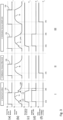
- the Fig. 2 and 3 describe various signals when monitoring the brakes.
- the Fig. 2(a) shows the time course of the voltage Ub at the brake 2, i.e. at the drive coil 3. This is usually a rectified alternating voltage, which is shown here in simplified form as a square-wave signal.
- the voltage Ub is controlled via the switches K_DC and/or K_AC (cf. Fig. 1 ) switched on or off.
- Fig. 2(b) the coil current Ib is shown.
- the coil current Ib initially increases exponentially. Due to the electromotive force induced by the armature movement, the current curve has a characteristic dent 13 at point (1).
- the braking torque M has also decayed ( Fig. 2(c) ), so that the output relays 9 close ( Fig. 2(d) ).
- the combined signal RDY ( Fig. 2(e) ) indicates whether a detection was rejected and is always set in the example shown, i.e. relay K3 is closed.
- Such a dent 13 is also present when the voltage Ub is switched off by the alternating voltage switch K_AC. From time (2a), after dent 13, the braking torque M begins to rise.
- Fig. 3 I normal operation is as in Fig. 2 shown.
- the relays K1/K2 are reset ( Fig. 3 (d) ).
- the Fig. 3 II shows the current curve when the armature 4 does not open despite applying a voltage Ub. Due to the lack of mutual induction, the current Ib only increases exponentially according to II(b) and also decays exponentially again after the voltage Ub is switched off. The characteristic dents 13 are missing here. Due to the absence of the dents, the relays 9 are not switched, so that from time 2A an error signal f is displayed by the elevator control 10 and a corresponding error reaction occurs.
- Fig. 3 III shows the case in which the brake 2 opens correctly but no longer closes.
- relay 9 is closed so that normal function is signaled.
- the brake does not close.
- Ib drops to its minimum, no error is initially detected. If the current falls below I_min ( Fig. 3 (b) ) occurs first a reset of the relays K1/K2 ( Fig. 3 (d) ). Only when the brake is to be opened next time will there be no dent 13 in the current Ib due to the stuck armature 4. From this moment 3c a malfunction is detected and the error signal is set.
- the curve shape of the current Ib then changes from a right-hand bend to a left-hand bend.
- Criterion P25 here is that the second derivative Ib2 becomes positive.
- Criterion P30 is therefore that the first derivative Ib1 is positive.
- the shape of the curve changes from a left-hand curvature to a right-hand curvature.
- the criterion P35 is that the second derivative Ib2 becomes negative.
- Areas can be defined to fulfill the criteria.
- the limit values are selected so that a non-switching brake is not incorrectly evaluated as switching and a switching brake is not incorrectly evaluated as a non-switching brake. This increases the safety and availability of the brake.
- Fig. 4(b) shows the course when the brake does not switch, i.e. when the armature 4 does not move. Criterion P10 is still met. However, due to the missing dent 13, this condition remains, so that criterion P20 is not met.
- Fig. 5(a) shows accordingly Fig. 4(a) the criteria for recognizing a correct closing process of the brake 2.
- Two criteria are necessary here in the example. However, a different number of criteria can also be used or defined. In particular, the number of criteria can be equal to the number of criteria when opening.
- the curve shape shows a left curvature.
- the criterion P40 is therefore that the second derivative Ib2 is positive.
- the curve shape changes to a rightward bend, so that the second derivative has a sign change.
- the second criterion P50 is therefore that the second derivative Ib2 is negative.
- a correct movement of the armature 2 when closing the brake 2 therefore requires the fulfillment of criteria P40 and P50 in time sequence.
- Fig. 5(b) represents the situation when the brake does not close.
- the current Ib drops according to an exponential function.
- the curve shape shows a left curvature.
- the second derivative Ib2 is positive.
- Criterion P40 is met.
- the values or ranges for the criteria are chosen so that the closing of the brake is not signaled too early before the actual switching process and in normal operation the time of the switching process can be reliably determined. This increases the positioning accuracy or comfort, with the safety-relevant function monitoring of the brake only being carried out when the brake is opened, i.e. when the voltage Ub is switched on Fig. 4 he follows.
- Point Condition parameter Length of time P10 2nd derivative negative ⁇ -I_GRAD2_NEG_P10 T_P10 P20 1.
- the parameters and durations of the individual criteria depend on different conditions and must be determined individually for each brake.
- the voltage Ub of the drive coil 3 is also monitored according to the invention.
- a detected armature movement is therefore only rejected if the deviation of the supply voltage Ub was sufficiently strong to cause a change in the coil current Ib, which would lead to a detection of an armature movement. So only if the voltage fluctuation was strong enough to compensate for or create a dent 13. In particular, only then if the voltage deviation is in the correct direction.
- the current voltage Ub is stored as a reference value. Up to criterion P20, this voltage may only deviate downwards by a lower tolerance limit U(P10)-TOL_U_NEG, while an upward deviation is not critical. However, once criterion P20 is reached, an upper deviation is only permissible up to the upper tolerance limit U(P10)-TOL_U_POS, while from then on a downward deviation is not critical.
- the upper tolerance limit and lower tolerance limit can be determined relative to the reference value in P10, or can be dependent on the coil voltage Ub, or can be fixed values.
- voltage monitoring only takes place after criterion P10 has been met.
- the Fig. 9 shows a flowchart of an exemplary method according to the invention when opening the brake.
- a first step S1 the coil current Ib is monitored.
- step S2 it is checked whether the coil current Ib has exceeded a start threshold I_Start. If not, current monitoring is carried out in step S1.
- step S3 it is then checked in step S3 whether the first criterion P10 is met. If not, it is first checked in step S4 whether the time T_ON, in which the criterion is expected, has expired. If the time T_ON has not yet expired, the check continues to ensure that criterion P10 is met.
- step S5 if the time T_ON has expired, there is an error and an error is reported in step S5.
- the relay K1 or K2 belonging to the brake currently being monitored is not switched.
- step S6 the current voltage Ub is first saved as a reference value for voltage monitoring and voltage monitoring is started.
- step S7 it is now checked whether the criteria P20 to P35 are fulfilled one after the other within the time T_ON and the voltage is within the tolerance limits Fig. 8 lay. If even one criterion is not met, the system branches to step S5 and the relay K1 or K2 belonging to the brake currently being monitored is not switched. If the criteria are met but the voltage was outside the tolerance limits, the relays K1 and K2 are not switched and the RDY signal is also reset.
- step S8 Only if all criteria are met in the allotted time and the voltage Ub was within the tolerance limits will a positive feedback be given in step S8 by switching relays K1 or K2. The RDY signal then remains set.
- step S9 When the brake is closed, the current is monitored in step S9. After switching off the voltage Ub of the armature coil 3, the criteria P40 and P50 become in step S10 monitored in the expected times. If both criteria are met, a positive feedback is sent directly to the elevator control in step S12, otherwise a positive feedback is only given in step S11 after the current limit I_min is undershot.
Landscapes
- Engineering & Computer Science (AREA)
- Mechanical Engineering (AREA)
- Physics & Mathematics (AREA)
- Electromagnetism (AREA)
- Power Engineering (AREA)
- Transportation (AREA)
- Elevator Control (AREA)
- Braking Arrangements (AREA)
Claims (14)
- Procédé de surveillance d'un frein électromagnétique (2) selon lequel un courant de bobine (Ib) est enregistré pour détecter un mouvement d'induit, caractérisé en ce qu'un mouvement d'induit détecté est rejeté quand une tension d'alimentation (Ub) pour le courant de bobine (Ib) s'écarte trop d'une courbe prédéterminée, le mouvement d'induit détecté n'étant rejeté que si l'écart de la tension d'alimentation (Ub) s'est produit sur la plage temporelle sur laquelle le mouvement d'induit a été détecté.
- Procédé selon la revendication 1, caractérisé en ce qu'une surveillance d'un écart de la tension d'alimentation (Ub) par rapport à une courbe prédéfinie ne démarre que quand un critère de démarrage est rempli, en particulier quand le courant de bobine (Ib) dépasse une première valeur-seuil (I_Start).
- Procédé de surveillance d'un frein électromagnétique (2), en particulier selon une des revendications précédentes, selon lequel un courant de bobine (Ib) est enregistré pour détecter un mouvement d'induit, caractérisé en ce qu'un mouvement d'induit détecté est rejeté quand une tension d'alimentation (Ub) pour le courant de bobine (Ib) s'écarte trop d'une courbe prédéterminée, le mouvement d'induit détecté n'étant rejeté que si l'écart de la tension d'alimentation (Ub) a été suffisamment important pour provoquer une variation du courant de bobine (Ib) qui engendrerait une détection d'un mouvement d'induit.
- Procédé de surveillance d'un frein électromagnétique (2), en particulier selon une des revendications précédentes, selon lequel un courant de bobine (Ib) est enregistré pour détecter un mouvement d'induit, caractérisé en ce qu'un mouvement d'induit détecté est rejeté quand une tension d'alimentation (Ub) pour le courant de bobine (Ib) s'écarte trop d'une courbe prédéterminée, le mouvement d'induit détecté n'étant rejeté que si l'écart de la tension d'alimentation (Ub) présente une direction (hausse ou baisse) définie pour provoquer une variation du courant de bobine (Ib) qui engendrerait une détection d'un mouvement d'induit.
- Procédé selon une des revendications précédentes, caractérisé en ce que la tension d'alimentation (Ub) est filtrée, une caractéristique de filtrage étant choisie de sorte que les écarts dont la longueur temporelle et/ou le niveau est trop faible pour pouvoir déclencher une détection d'un mouvement d'induit sont exclus.
- Procédé de surveillance d'un frein électromagnétique (2), en particulier selon une des revendications précédentes, selon lequel un courant de bobine est enregistré pour détecter un mouvement d'induit, caractérisé en ce qu'au moins un critère qui est contrôlé pour la détection du mouvement d'induit est constitué au moins à partir de la dérivée seconde dans le temps de la valeur instantanée du courant de bobine.
- Procédé selon une des revendications précédentes, caractérisé en ce qu'en guise d'au moins un critère est utilisé un dépassement vers le haut ou vers le bas d'une valeur-seuil, la dérivée seconde dans le temps de la valeur instantanée du courant de bobine.
- Procédé selon une des revendications précédentes, caractérisé en ce qu'une série de critères se succédant dans le temps sont constitués à partir de la valeur instantanée du courant de bobine (Ib), de sa dérivée première dans le temps (Ib1) et de sa dérivée seconde dans le temps (Ib2), lesquels doivent être remplis les uns après les autres pour détecter un mouvement d'induit.
- Procédé selon la revendication 8, caractérisé en ce que cinq critères (P10, P20, P25, P30, P35) doivent être remplis lors de l'ouverture du frein, le premier critère (P10) étant que la dérivée seconde (Ib2) de la valeur instantanée du courant de bobine (Ib) est négative, le deuxième critère (P20) étant que la dérivée première (Ib1) de la valeur instantanée du courant de bobine (Ib) est négative, le troisième critère (P25) étant que la dérivée seconde (Ib2) de la valeur instantanée du courant de bobine (Ib) est positive, le quatrième critère (P30) étant que la dérivée première (Ib1) de la valeur instantanée du courant de bobine (Ib) est positive et le cinquième critère (P35) étant que la dérivée seconde (Ib2) de la valeur instantanée du courant de bobine (Ib) est négative.
- Procédé selon la revendication 9, caractérisé en ce qu'une surveillance d'un écart de la tension d'alimentation (Ub) par rapport à une courbe prédéfinie ne démarre que quand le premier critère (P10) est rempli, en particulier la tension actuelle étant enregistrée comme valeur de référence.
- Procédé selon une des revendications 8 à 10, caractérisé en ce que lors de la fermeture du frein (2), deux critères (P40, P50) doivent être remplis, le premier critère (P40) étant que la dérivée seconde (Ib2) de la valeur instantanée du courant de bobine (Ib) est positive et le deuxième critère (P50) étant que la dérivée seconde (Ib2) de la valeur instantanée du courant de bobine (Ib) est négative.
- Dispositif de surveillance de frein doté d'un dispositif de détection (7) avec lequel un mouvement d'induit peut être détecté en évaluant un courant de bobine (Ib), caractérisé en ce que ce dispositif de surveillance de frein possède un dispositif de contrôle (7) qui est adapté pour surveiller une tension d'alimentation (Ub) pour le courant de bobine (Ib), de sorte qu'un mouvement d'induit détecté est rejeté quand une tension d'alimentation (Ub) pour le courant de bobine (Ib) s'écarte trop d'une courbe prédéterminée, une sortie qui indique un mouvement d'induit détecté rejeté lorsqu'un écart de la tension d'alimentation a été identifié étant présente.
- Dispositif de surveillance de frein, en particulier selon la revendication 12, doté d'un dispositif de détection (7) avec lequel un mouvement d'induit peut être détecté en évaluant un courant de bobine (Ib), caractérisé en ce que ce dispositif de surveillance de frein possède un dispositif de contrôle (7) qui est adapté pour surveiller une tension d'alimentation (Ub) pour le courant de bobine (Ib), de sorte qu'un mouvement d'induit détecté est rejeté quand une tension d'alimentation (Ub) pour le courant de bobine (Ib) s'écarte trop d'une courbe prédéterminée, une unité de contrôle de vraisemblance (7) avec laquelle le dispositif de détection (7) peut être désactivé quand un écart de la tension d'alimentation n'est pas approprié pour produire un faux mouvement d'induit étant présente.
- Dispositif de surveillance de frein selon la revendication 12 ou 13, caractérisé en ce qu'un procédé selon une des revendications 1 à 11 peut être mis en oeuvre.
Applications Claiming Priority (1)
| Application Number | Priority Date | Filing Date | Title |
|---|---|---|---|
| DE102019116221.1A DE102019116221A1 (de) | 2019-06-14 | 2019-06-14 | Verfahren und Vorrichtung zur Überwachung einer elektromagnetischen Bremse |
Publications (2)
| Publication Number | Publication Date |
|---|---|
| EP3798176A1 EP3798176A1 (fr) | 2021-03-31 |
| EP3798176B1 true EP3798176B1 (fr) | 2024-02-21 |
Family
ID=71094134
Family Applications (1)
| Application Number | Title | Priority Date | Filing Date |
|---|---|---|---|
| EP20179643.0A Active EP3798176B1 (fr) | 2019-06-14 | 2020-06-12 | Procédé et dispositif de surveillance d'un frein électromagnétique |
Country Status (2)
| Country | Link |
|---|---|
| EP (1) | EP3798176B1 (fr) |
| DE (1) | DE102019116221A1 (fr) |
Families Citing this family (1)
| Publication number | Priority date | Publication date | Assignee | Title |
|---|---|---|---|---|
| DE102021209291A1 (de) | 2021-08-24 | 2023-03-02 | Continental Automotive Technologies GmbH | Verfahren zur Überwachung eines Blockierstößels und Betätigungseinheit |
Family Cites Families (5)
| Publication number | Priority date | Publication date | Assignee | Title |
|---|---|---|---|---|
| DE10314390B4 (de) * | 2003-03-28 | 2012-11-22 | Pintsch Bamag Antriebs- Und Verkehrstechnik Gmbh | Verfahren und Vorrichtung zum Überwachen einer elektromagnetisch betätigbaren Bremse |
| CN100546895C (zh) * | 2004-09-24 | 2009-10-07 | 三菱电机株式会社 | 升降机制动器的电枢运动检测装置和电枢位置估测装置 |
| WO2009024168A1 (fr) * | 2007-08-20 | 2009-02-26 | Otis Elevator Company | Appareil et procédé de surveillance d'un frein électromagnétique |
| DE102012007863A1 (de) * | 2012-04-18 | 2013-10-24 | Ortlinghaus-Werke Gmbh | Verfahren zur Steuerung des Drehmomentes bei elektromagnetischen Bremsen, Kupplungen und Kupplungs-Brems-Kombinationen |
| EP3239086B1 (fr) * | 2016-04-28 | 2022-06-01 | KONE Corporation | Solution pour contrôler un frein d'ascenseur |
-
2019
- 2019-06-14 DE DE102019116221.1A patent/DE102019116221A1/de active Pending
-
2020
- 2020-06-12 EP EP20179643.0A patent/EP3798176B1/fr active Active
Also Published As
| Publication number | Publication date |
|---|---|
| DE102019116221A1 (de) | 2020-12-17 |
| EP3798176A1 (fr) | 2021-03-31 |
Similar Documents
| Publication | Publication Date | Title |
|---|---|---|
| DE3614979C2 (de) | Sicherheitssystem für eine Druckmaschine | |
| DE102015005198B4 (de) | Bremsantriebssteuervorrichtung mit Regelwidrigkeitsdetektion | |
| EP2845072B1 (fr) | Appareil de commutation | |
| DE19921828A1 (de) | Verfahren zum Betreiben eines Stellungsreglers und insbesondere dieses Verfahren anwendender Stellungsregler | |
| DE102012103015A1 (de) | Sicherheitsschaltvorrichtung mit Schaltelement im Hilfskontaktstrompfad | |
| EP2842147B1 (fr) | Procédé de surveillance d'un sélecteur de prises | |
| EP3898477B1 (fr) | Procédé et commande du frein permettant de commander un frein d'une installation d'ascenseur | |
| EP3798176B1 (fr) | Procédé et dispositif de surveillance d'un frein électromagnétique | |
| EP2587512B1 (fr) | Commutateur orienté vers la sécurité | |
| EP1253490A2 (fr) | Procédé et dispositif de surveillance sécurisée de la vitesse | |
| EP1629513B1 (fr) | Dispositif de commande destine a des composants critiques pour la securite et procede correspondant | |
| EP3855467B1 (fr) | Procédé et dispositif de commande d'un relais | |
| DE102004041672B4 (de) | Notbremseinrichtung und Bremssystem für ein Schienenfahrzeug sowie Verfahren zum Sicherstellen einer Notbremsfunktion bei Schienenfahrzeugen | |
| EP3704048B1 (fr) | Dispositif de surveillance de sécurité destiné à surveiller des conditions relatives à la sécurité dans une installation de transport de personnes ainsi que procédé de fonctionnement d'un tel dispositif | |
| DE4413047C2 (de) | Verfahren und Vorrichtung zur Bremsüberwachung des Gleichstrommotors einer Druckmaschine | |
| DE102016214419A1 (de) | Sanftstarter, Betriebsverfahren und Schaltsystem | |
| EP3306329B1 (fr) | Procédé de surveillance centrale de changements d'état d'une pluralité de composants pour installations haute tension à partir de 1 kv. | |
| EP2215533B1 (fr) | Dispositif de commande pour un système de commutation de sécurité à surveillance intégrée de la tension d'alimentation | |
| EP2899872B1 (fr) | Système d'alimentation pour un entraînement à courant continu et procédé de désactivation de sécurité d'un entraînement à courant continu | |
| DE4031427A1 (de) | Verfahren und vorrichtung zum energiereduzierten betrieb eines elektromagnetischen stellgliedes | |
| EP3288057A1 (fr) | Commutateur oriente vers la securite | |
| WO2021083974A1 (fr) | Procédé de freinage rapide d'un véhicule ferroviaire à spécifications de freinage définies | |
| BE1030869B1 (de) | Verfahren zur Ansteuerung eines elektromechanischen Schaltelements | |
| DE102012012047A1 (de) | Antriebsregler und Verfahren zur Stillsetzung einer Achse | |
| EP3644143B1 (fr) | Ensemble périphérique à paramétrage automatique |
Legal Events
| Date | Code | Title | Description |
|---|---|---|---|
| PUAI | Public reference made under article 153(3) epc to a published international application that has entered the european phase |
Free format text: ORIGINAL CODE: 0009012 |
|
| STAA | Information on the status of an ep patent application or granted ep patent |
Free format text: STATUS: THE APPLICATION HAS BEEN PUBLISHED |
|
| AK | Designated contracting states |
Kind code of ref document: A1 Designated state(s): AL AT BE BG CH CY CZ DE DK EE ES FI FR GB GR HR HU IE IS IT LI LT LU LV MC MK MT NL NO PL PT RO RS SE SI SK SM TR |
|
| AX | Request for extension of the european patent |
Extension state: BA ME |
|
| STAA | Information on the status of an ep patent application or granted ep patent |
Free format text: STATUS: REQUEST FOR EXAMINATION WAS MADE |
|
| 17P | Request for examination filed |
Effective date: 20210929 |
|
| RBV | Designated contracting states (corrected) |
Designated state(s): AL AT BE BG CH CY CZ DE DK EE ES FI FR GB GR HR HU IE IS IT LI LT LU LV MC MK MT NL NO PL PT RO RS SE SI SK SM TR |
|
| GRAP | Despatch of communication of intention to grant a patent |
Free format text: ORIGINAL CODE: EPIDOSNIGR1 |
|
| STAA | Information on the status of an ep patent application or granted ep patent |
Free format text: STATUS: GRANT OF PATENT IS INTENDED |
|
| RIC1 | Information provided on ipc code assigned before grant |
Ipc: B66B 5/00 20060101ALI20230201BHEP Ipc: F16D 59/02 20060101ALI20230201BHEP Ipc: H01F 7/18 20060101ALI20230201BHEP Ipc: B60T 17/22 20060101ALI20230201BHEP Ipc: B66D 5/30 20060101AFI20230201BHEP |
|
| INTG | Intention to grant announced |
Effective date: 20230306 |
|
| GRAJ | Information related to disapproval of communication of intention to grant by the applicant or resumption of examination proceedings by the epo deleted |
Free format text: ORIGINAL CODE: EPIDOSDIGR1 |
|
| GRAL | Information related to payment of fee for publishing/printing deleted |
Free format text: ORIGINAL CODE: EPIDOSDIGR3 |
|
| GRAS | Grant fee paid |
Free format text: ORIGINAL CODE: EPIDOSNIGR3 |
|
| STAA | Information on the status of an ep patent application or granted ep patent |
Free format text: STATUS: REQUEST FOR EXAMINATION WAS MADE |
|
| INTC | Intention to grant announced (deleted) | ||
| P01 | Opt-out of the competence of the unified patent court (upc) registered |
Effective date: 20230713 |
|
| GRAP | Despatch of communication of intention to grant a patent |
Free format text: ORIGINAL CODE: EPIDOSNIGR1 |
|
| STAA | Information on the status of an ep patent application or granted ep patent |
Free format text: STATUS: GRANT OF PATENT IS INTENDED |
|
| INTG | Intention to grant announced |
Effective date: 20230907 |
|
| GRAA | (expected) grant |
Free format text: ORIGINAL CODE: 0009210 |
|
| STAA | Information on the status of an ep patent application or granted ep patent |
Free format text: STATUS: THE PATENT HAS BEEN GRANTED |
|
| AK | Designated contracting states |
Kind code of ref document: B1 Designated state(s): AL AT BE BG CH CY CZ DE DK EE ES FI FR GB GR HR HU IE IS IT LI LT LU LV MC MK MT NL NO PL PT RO RS SE SI SK SM TR |
|
| REG | Reference to a national code |
Ref country code: GB Ref legal event code: FG4D Free format text: NOT ENGLISH |
|
| REG | Reference to a national code |
Ref country code: CH Ref legal event code: EP |
|
| REG | Reference to a national code |
Ref country code: DE Ref legal event code: R096 Ref document number: 502020007058 Country of ref document: DE |
|
| REG | Reference to a national code |
Ref country code: IE Ref legal event code: FG4D Free format text: LANGUAGE OF EP DOCUMENT: GERMAN |