EP3798142A1 - Holding device for the flexible treatment of pharmaceutical packaging materials - Google Patents
Holding device for the flexible treatment of pharmaceutical packaging materials Download PDFInfo
- Publication number
- EP3798142A1 EP3798142A1 EP19199683.4A EP19199683A EP3798142A1 EP 3798142 A1 EP3798142 A1 EP 3798142A1 EP 19199683 A EP19199683 A EP 19199683A EP 3798142 A1 EP3798142 A1 EP 3798142A1
- Authority
- EP
- European Patent Office
- Prior art keywords
- holding device
- container
- container holding
- containers
- closure system
- Prior art date
- Legal status (The legal status is an assumption and is not a legal conclusion. Google has not performed a legal analysis and makes no representation as to the accuracy of the status listed.)
- Granted
Links
Images


Classifications
-
- B—PERFORMING OPERATIONS; TRANSPORTING
- B01—PHYSICAL OR CHEMICAL PROCESSES OR APPARATUS IN GENERAL
- B01L—CHEMICAL OR PHYSICAL LABORATORY APPARATUS FOR GENERAL USE
- B01L9/00—Supporting devices; Holding devices
-
- A—HUMAN NECESSITIES
- A61—MEDICAL OR VETERINARY SCIENCE; HYGIENE
- A61J—CONTAINERS SPECIALLY ADAPTED FOR MEDICAL OR PHARMACEUTICAL PURPOSES; DEVICES OR METHODS SPECIALLY ADAPTED FOR BRINGING PHARMACEUTICAL PRODUCTS INTO PARTICULAR PHYSICAL OR ADMINISTERING FORMS; DEVICES FOR ADMINISTERING FOOD OR MEDICINES ORALLY; BABY COMFORTERS; DEVICES FOR RECEIVING SPITTLE
- A61J1/00—Containers specially adapted for medical or pharmaceutical purposes
- A61J1/14—Details; Accessories therefor
- A61J1/16—Holders for containers
-
- B—PERFORMING OPERATIONS; TRANSPORTING
- B65—CONVEYING; PACKING; STORING; HANDLING THIN OR FILAMENTARY MATERIAL
- B65D—CONTAINERS FOR STORAGE OR TRANSPORT OF ARTICLES OR MATERIALS, e.g. BAGS, BARRELS, BOTTLES, BOXES, CANS, CARTONS, CRATES, DRUMS, JARS, TANKS, HOPPERS, FORWARDING CONTAINERS; ACCESSORIES, CLOSURES, OR FITTINGS THEREFOR; PACKAGING ELEMENTS; PACKAGES
- B65D25/00—Details of other kinds or types of rigid or semi-rigid containers
- B65D25/02—Internal fittings
- B65D25/10—Devices to locate articles in containers
-
- A—HUMAN NECESSITIES
- A61—MEDICAL OR VETERINARY SCIENCE; HYGIENE
- A61J—CONTAINERS SPECIALLY ADAPTED FOR MEDICAL OR PHARMACEUTICAL PURPOSES; DEVICES OR METHODS SPECIALLY ADAPTED FOR BRINGING PHARMACEUTICAL PRODUCTS INTO PARTICULAR PHYSICAL OR ADMINISTERING FORMS; DEVICES FOR ADMINISTERING FOOD OR MEDICINES ORALLY; BABY COMFORTERS; DEVICES FOR RECEIVING SPITTLE
- A61J1/00—Containers specially adapted for medical or pharmaceutical purposes
- A61J1/05—Containers specially adapted for medical or pharmaceutical purposes for collecting, storing or administering blood, plasma or medical fluids ; Infusion or perfusion containers
- A61J1/06—Ampoules or carpules
-
- A—HUMAN NECESSITIES
- A61—MEDICAL OR VETERINARY SCIENCE; HYGIENE
- A61J—CONTAINERS SPECIALLY ADAPTED FOR MEDICAL OR PHARMACEUTICAL PURPOSES; DEVICES OR METHODS SPECIALLY ADAPTED FOR BRINGING PHARMACEUTICAL PRODUCTS INTO PARTICULAR PHYSICAL OR ADMINISTERING FORMS; DEVICES FOR ADMINISTERING FOOD OR MEDICINES ORALLY; BABY COMFORTERS; DEVICES FOR RECEIVING SPITTLE
- A61J1/00—Containers specially adapted for medical or pharmaceutical purposes
- A61J1/14—Details; Accessories therefor
- A61J1/1412—Containers with closing means, e.g. caps
-
- A—HUMAN NECESSITIES
- A61—MEDICAL OR VETERINARY SCIENCE; HYGIENE
- A61M—DEVICES FOR INTRODUCING MEDIA INTO, OR ONTO, THE BODY; DEVICES FOR TRANSDUCING BODY MEDIA OR FOR TAKING MEDIA FROM THE BODY; DEVICES FOR PRODUCING OR ENDING SLEEP OR STUPOR
- A61M5/00—Devices for bringing media into the body in a subcutaneous, intra-vascular or intramuscular way; Accessories therefor, e.g. filling or cleaning devices, arm-rests
- A61M5/002—Packages specially adapted therefor, e.g. for syringes or needles, kits for diabetics
-
- B—PERFORMING OPERATIONS; TRANSPORTING
- B65—CONVEYING; PACKING; STORING; HANDLING THIN OR FILAMENTARY MATERIAL
- B65D—CONTAINERS FOR STORAGE OR TRANSPORT OF ARTICLES OR MATERIALS, e.g. BAGS, BARRELS, BOTTLES, BOXES, CANS, CARTONS, CRATES, DRUMS, JARS, TANKS, HOPPERS, FORWARDING CONTAINERS; ACCESSORIES, CLOSURES, OR FITTINGS THEREFOR; PACKAGING ELEMENTS; PACKAGES
- B65D25/00—Details of other kinds or types of rigid or semi-rigid containers
- B65D25/02—Internal fittings
- B65D25/10—Devices to locate articles in containers
- B65D25/101—Springs, elastic lips, or other resilient elements to locate the articles by pressure
-
- B—PERFORMING OPERATIONS; TRANSPORTING
- B01—PHYSICAL OR CHEMICAL PROCESSES OR APPARATUS IN GENERAL
- B01L—CHEMICAL OR PHYSICAL LABORATORY APPARATUS FOR GENERAL USE
- B01L2300/00—Additional constructional details
- B01L2300/04—Closures and closing means
-
- B—PERFORMING OPERATIONS; TRANSPORTING
- B01—PHYSICAL OR CHEMICAL PROCESSES OR APPARATUS IN GENERAL
- B01L—CHEMICAL OR PHYSICAL LABORATORY APPARATUS FOR GENERAL USE
- B01L2300/00—Additional constructional details
- B01L2300/04—Closures and closing means
- B01L2300/041—Connecting closures to device or container
- B01L2300/042—Caps; Plugs
-
- B—PERFORMING OPERATIONS; TRANSPORTING
- B65—CONVEYING; PACKING; STORING; HANDLING THIN OR FILAMENTARY MATERIAL
- B65B—MACHINES, APPARATUS OR DEVICES FOR, OR METHODS OF, PACKAGING ARTICLES OR MATERIALS; UNPACKING
- B65B7/00—Closing containers or receptacles after filling
- B65B7/16—Closing semi-rigid or rigid containers or receptacles not deformed by, or not taking-up shape of, contents, e.g. boxes or cartons
- B65B7/28—Closing semi-rigid or rigid containers or receptacles not deformed by, or not taking-up shape of, contents, e.g. boxes or cartons by applying separate preformed closures, e.g. lids, covers
- B65B7/2821—Closing semi-rigid or rigid containers or receptacles not deformed by, or not taking-up shape of, contents, e.g. boxes or cartons by applying separate preformed closures, e.g. lids, covers applying plugs or threadless stoppers
Definitions
- the present invention relates to a container holding device for holding a plurality of containers, each container comprising a top region, a neck region, a shoulder region and a body region, wherein the holding device comprises a base plate and holding elements which are preferably in the form of clips.
- the invention also relates to a kit comprising a container holding device and a closure system holding device, to a process for producing closed containers and to the use of a holding device.
- a holding device for containers also named “nest”
- the nests are usually delivered to a customer, such as a pharmaceutical company or filler, sterile packaged in a transport or packaging container (also named "tub").
- a transport or packaging container also named "tub”
- the tubs are opened under sterile conditions, e.g. in a clean room. Further processing takes place either with the nest still accommodated in the tub, or after removal of the nest of the tub.
- Further processing the containers may include a step of filling the containers with a substance, e.g. a pharmaceutical composition, in liquid form and sealing the pre-filled containers with stoppers, plungers or the like. After the further processing, the containers may be sterile packaged again in a tub, for delivery to final customers.
- necked containers are held at the rolled edge, i.e. at the widened upper rims adjacent narrow neck portions, by means of resilient holding arms, such as clips.
- the bodies and bottoms of the vials are freely accessible, which may be required for further processing, such as freeze-drying (lyophilization).
- An example of such a holding device known from the prior art are the nests disclosed, for example, in figure 2f of DE 10 1012 110339 A1 .
- These nests comprise a base plate comprising holes in a defined array, wherein at the upper side of the base plate resilient retaining tongues are arranged around each hole.
- the containers are hanging in the holes of the nests and are held in position by the tongues that are located beneath the rolled edge or the containers.
- the base plate is moved downwards (or, if the containers are standing on a substrate such as a table of the pharmaceutical filling machine, the containers are moved upwards by raising the table) the containers are closed at the top side.
- Closing is usually accomplished by pressing a stopper in the open end of the containers, followed by sealing the rolled edge of the containers by means of a cap.
- This process can also be simplified by using one-part closure systems such as the RayDyLyo® closure system (ARaymondlife SASU, France), which comprise a combination of the stopper and the cap.
- closing the containers in the container nest is accomplished by applying a further nest (cap nest) that comprises the closure systems in an arrangement that corresponds to the arrangement of the containers in the container nest.
- a further nest that comprises the closure systems in an arrangement that corresponds to the arrangement of the containers in the container nest.
- the two nests are pressed against each other.
- the first step is to pull the cap nest upwards and the second step is to pull the containers out of the vial nest upwards.
- the above described nests may also be suitable for weighing the containers in the nest. For weighing the container is also lifted within the clip receptacles to create enough space for the weighing process. However, if the vials are touched by the tongues, the weighing result may be affected. Therefore, as much free space as possible must be created. Since these steps with today's nests require very high precision, which can often only be guaranteed by the use of robots, the vials are usually removed from the nest for the weighing and closing steps. Removal of the containers out of the nest, however, places certain demands on the dimensional design of the nest.
- containers nests such as those disclosed in DE 10 2012 110 339 A1 are, to a certain extent, disadvantageous for bigger containers having an outer diameter of 40 mm or even larger if these containers, as stated above, have to be raised within the nest to apply the closure systems or have to be removed out of the nest for certain process steps.
- the tongues As the tongues are holding the containers beneath the rolled edge, they must grip with the diameter of that edge.
- the nest must have an opening with at least the body diameter of the container so that the container can be lifted out of the nest.
- diameter ratios that deviate from the standard, such as particularly large vials, require very large holding elements, as the crimp diameters usually do not exceed 20 mm, but the body diameters can reach values up to 40 mm (50R) or 47 mm (100R).
- a container nest preferably a vial nest, which holds the containers, preferably the vials, in a larger density compared to the container nests known from the prior art.
- a container nest preferably a vial nest, which helps to increase the process economy in a pharmaceutical filling station, particularly when it comes to the step of removing the closed containers, preferably the closed vials, out of the container nest.
- a contribution to solving at least one of the objects according to the invention is made by an embodiment 1 of a container holding device for holding one or more containers, each container comprising a top region with a top edge, a bottom edge and an outer diameter d1 , a neck region having an outer diameter d2 ⁇ d1 , a shoulder region and a body region with an outer diameter d3 > d1 , wherein the container holding device comprises
- the bottom surface of the base plate is the surface that, if containers are hanging in the holding device in position p1, is facing towards the top region of the container, which preferably is in the form of a rolled edge.
- the expression "the holding elements do not exert any force on the outer surface of the container that is, with respect to said central symmetry axis L axis , radial" is preferably understood in such a way that the holding elements do not press against the outer surface of the neck region of a container that is hanging in the holding device in position p1, but that the holding elements simply contact the outer surface of the container at the bottom edge of the top region, i. e. they preferably contact the container at the underside of the rolled edge.
- the holding elements are preferably adapted and arranged such that they do not increase the force that is necessary to move the container from position p1 to position p2.
- the holding elements are preferably adapted to the containers so that containers with rolled edge rest loosely with the bottom side of the rolled edge on the holding elements.
- the container holding device is designed according to its embodiment 1, wherein the container is a pharmaceutical container that is rotationally symmetrical around a longitudinal axis of the container and that has at least one opening at the top edge of the container.
- the container holding device is designed according to its embodiment 2, wherein the container is selected from the group consisting of a vial, a vartridge, an ampule, a cartridge or a syringe.
- the container holding device is designed according to its embodiment 3, wherein the container is vial, preferably a vial in which the top region has the shape of a rolled edge.
- the container holding device according to the present invention is thus preferably a holding device for vials, i. e. a vial nest.
- the container holding device is designed according to anyone of its embodiments 1 to 5, wherein holes are arranged in a regular arrangement of rows and columns distributed on the base plate, wherein the rows and columns are arranged regularly offset from each other and form a recurring arrangement.
- This regular arrangement is advantageous for automated treatment of the containers.
- the container holding device is designed according to anyone of its embodiments 1 to 5, wherein the holding elements are arranged along a circle around each hole.
- the container holding device is designed according to anyone of its embodiments 1 to 6, wherein two, three, four or more holding elements are arranged along a circle around each hole.
- three or four holding elements are arranged at regular intervals along a circle around the individual holes on the underside of the base plate.
- the container holding device is designed according to anyone of its embodiments 1 to 7, wherein the holding elements are designed in the form of clip.
- the container holding device is designed according to its embodiment 8, wherein each clip comprises
- the container holding device is designed according to its embodiments 8 or 9, wherein the clips are in the form of a flexible holding arm.
- the flexible holding arm comprises a holding nose that is located at the bottom part of the flexible holding arm and that is adapted and arranged to hold a container at the bottom edge of the top region, i. e. beneath the rolled edge.
- the container holding device is designed according to anyone of its embodiments 8 to 10, wherein the clips arranged obliquely below the base plate so that the clips, when an object that has the same diameter or almost the same diameter as the hole is introduced into the hole from the upper surface of the base plate, are pushed away from the central symmetry axis L axis of the holes by the approaching object.
- the container holding device is designed according to its embodiment 11, wherein the clips comprise a substantially plane inner surface that is directed towards the central symmetry axis L axis of the holes, wherein a straight line that is tangentially applied to the inner surface and that runs in the same plane as the central symmetry axis L axis of the holes includes an angle ⁇ with the central symmetry axis L axis of the holes.
- the container holding device is designed according to its embodiment 12, wherein ⁇ is in the range from 1 to 45 degree, preferably in the range from 1 to 30 degree, more preferably 1.5 to 20 degree, more preferably 1.5 to 15 degree and even more preferably in the range from 2 to 5 degree.
- the diameter of the holes in the base plate is smaller than the diameter of the body region of the containers that can be held in the container holding device.
- the container holding device is designed according to its embodiment 14, wherein the following condition is fulfilled: d 4 ⁇ 0.99 ⁇ d 3 ; preferably d4 ⁇ 0.97 ⁇ d3 ; more preferably d4 ⁇ 0.95 ⁇ d3 ; most preferably d4 ⁇ 0.93 ⁇ d3.
- the container holding device is designed according to anyone of its embodiments 1 to 15, wherein the holes have a diameter d4 > d1.
- the diameter of the holes in the base plate is larger than the diameter of the top region of the containers that can be held in the container holding device. If the containers are thus lifted from position p1 into position p2 , the holding elements can be adapted and arranged in such a way that the top region of the container, preferably the rolled edge of a vial, protrudes beyond the upper surface of the base plate so that, for example, it is easier to close the containers with a closure system.
- the container holding device is designed according to its embodiment 16, wherein the following condition is fulfilled: d 4 ⁇ 1.25 ⁇ d 1 ; preferably d4 ⁇ 1.2 ⁇ d1; more preferably d4 ⁇ 1.15 ⁇ d1; more preferably d4 ⁇ 1.1 ⁇ d1; most preferably d4 ⁇ 1.05 ⁇ d1.
- the container holding device is designed according to its embodiment 16 or 17, wherein d4 ⁇ d3 and wherein the following condition is fulfilled: d 4 > 1.25 ⁇ d 1 ; preferably d4 > 1.3 ⁇ d1; more preferably d4 > 1.35 ⁇ d1; more preferably d4 > 1.4 ⁇ d1; more preferably d4 > 1.45 ⁇ d1; more preferably d4 > 1.5 ⁇ d1; more preferably d4 > 1.55 ⁇ d1; most preferably d4 > 1.6 ⁇ d1.
- the container holding device is designed according to anyone of its embodiments 1 to 18, wherein the following condition is fulfilled: d 1 ⁇ d 4 ⁇ d 3.
- the container holding device is designed according to anyone of its embodiments 1 to 19, wherein the holding elements are designed as holding elements, preferably in the form of elastic clips, but have sufficient elasticity to be pivoted or folded away when the container holding device is removed from the top region of the containers or when the containers are pulled downward out of the container holding device.
- the holding elements are therefore preferably made of a plastic material.
- the container holding device is designed according to its embodiment 20, wherein plastic material fulfills at least one of the following conditions:
- the container holding device is designed according to anyone of its embodiment 1 to 21, wherein the base plate has a width in the range from 150 to 300 cm, preferably in the range from 175 to 275 cm and most preferably in the range from 200 to 250 cm, and a length in the range from 300 to 450 cm, preferably in the range from 325 to 425 cm and most preferably in the range from 350 to 400 cm container.
- the container holding device is designed according to anyone of its embodiment 1 to 22, wherein the container holding device further comprises one or more containers that are hanging in position p1.
- the container holding device is designed according to its embodiment 23, wherein the container holding device is a vial nest designated to accommodate vials with a size designation "2R", “3R”, or “4R” according to DIN EN ISO 8362-1:2016-06 and wherein the container holding device comprises 80 to 140 vial, preferably 90 to 120 vials and even more preferably 100 to 110 to vials that are held in position p1.
- the container holding device is designed according to its embodiment 24, wherein the diameter of the holes ( d4 ) in the base plate is in the range from 13 to 20 mm, preferably in the range from 15 to 19 mm and more preferably in the range from 16 to 18 mm.
- the container holding device is designed according to its embodiment 24 or 25, wherein d 4 ⁇ 1.35 ⁇ d 1 ; preferably d4 ⁇ 1.3 ⁇ d1.
- the container holding device is designed according to anyone of its embodiments 24 to 26, wherein d4 ⁇ d3 and wherein d 4 > 1.4 ⁇ d 1 ; preferably d4 > 1.45 ⁇ d1.
- the container holding device is designed according to its embodiment 23, wherein the container holding device is a vial nest designated to accommodate vials with a size designation "6R", “8R”, “10R” or “15R” according to DIN EN ISO 8362-1:2016-06 and wherein the container holding device comprises 40 to 68 vial, preferably 44 to 58 vials and even more preferably 48 to 56 vials that are held in position p1.
- the container holding device is designed according to its embodiment 28, wherein the diameter of the holes ( d4 ) in the base plate is in the range from 20 to 35 mm, preferably in the range from 22 to 30 mm and more preferably in the range from 24 to 26 mm.
- the container holding device is designed according to its embodiment 26 or 27, wherein d 4 ⁇ 1.25 ⁇ d 1 ; preferably d4 ⁇ 1.2 ⁇ d1.
- the container holding device is designed according to anyone of its embodiments 28 to 30, wherein d4 ⁇ d3 and wherein d 4 > 1.3 ⁇ d 1 ; preferably d4 > 1.35 ⁇ d1.
- the container holding device is designed according to its embodiment 23, wherein the container holding device is a vial nest designated to accommodate vials with a size designation "20R", “25R” or “30R” according to DIN EN ISO 8362-1:2016-06 and wherein the container holding device comprises 20 to 38 vial, preferably 22 to 36 vials and even more preferably 24 to 30 vials that are held in position p1.
- the container holding device is designed according to its embodiment 32, wherein the diameter of the holes ( d4 ) in the base plate is in the range from 20 to 35 mm, preferably in the range from 22 to 30 mm and more preferably in the range from 24 to 26 mm.
- the container holding device is designed according to its embodiment 32 or 33, wherein d 4 ⁇ 1.25 ⁇ d 1 ; preferably d4 ⁇ 1.2 ⁇ d1.
- the container holding device is designed according to anyone of its embodiments 32 to 34, wherein d4 ⁇ d3 and wherein d 4 > 1.3 ⁇ d 1 ; preferably d4 > 1.35 ⁇ d1.
- the container holding device is designed according to its embodiment 23, wherein the container holding device is a vial nest designated to accommodate vials with a size designation "50R" according to DIN EN ISO 8362-1:2016-06 and wherein the container holding device comprises 10 to 30 vial, preferably 12 to 25 vials and even more preferably 15 to 20 vials that are held in position p1.
- the container holding device is designed according to its embodiment 36, wherein the diameter of the holes ( d4 ) in the base plate is in the range from 20 to 35 mm, preferably in the range from 22 to 30 mm and more preferably in the range from 24 to 26 mm.
- the container holding device is designed according to its embodiment 32 or 33, wherein d 4 ⁇ 1.25 ⁇ d 1 ; preferably d4 ⁇ 1.2 ⁇ d1.
- the container holding device is designed according to its embodiments 36 to 38, wherein d4 ⁇ d3 and wherein d 4 > 1.3 ⁇ d 1 ; preferably d4 > 1.35 ⁇ d1.
- the container holding device is designed according to its embodiment 23, wherein the container holding device is a vial nest designated to accommodate vials with a size designation "100R" according to DIN EN ISO 8362-1:2016-06 and wherein the container holding device comprises 8 to 20 vial, preferably 10 to 18 vials and even more preferably 12 to 15 vials that are held in position p1.
- the container holding device is designed according to its embodiment 40, wherein the diameter of the holes ( d4 ) in the base plate is in the range from 20 to 35 mm, preferably in the range from 22 to 30 mm and more preferably in the range from 24 to 26 mm.
- the container holding device is designed according to its embodiment 40 or 41, wherein d 4 ⁇ 1.25 ⁇ d 1 ; preferably d4 ⁇ 1.2 ⁇ d1 .
- the container holding device is designed according to anyone of its embodiments 40 to 42, wherein d4 ⁇ d3 and wherein d 4 > 1.3 ⁇ d 1 ; preferably d4 > 1.35 ⁇ d1.
- a contribution to solving at least one of the objects according to the invention is also made by an embodiment 1 of a kit, comprising
- the kit is designed according to its embodiment 1, wherein the closure cup holding device comprises a base plate having an upper surface and a bottom surface, and closure system holding elements that are located at the upper surface or the bottom surface of the base plate, wherein the closure system holding elements are adapted and arranged such that, when the container holding device and the closure system holding device are pressed together in order to close the containers in the container holding device with the closure systems in the closure system holding device, the holding elements of the container holding device are pushed away from the central symmetry axis L axis by the approaching closure system holding elements.
- the kit is designed according to its embodiment 1, wherein the closure systems in the closure system holding device have an outer diameter d5 such that, when the container holding device and the closure system holding device are pressed together in order to close the containers in the container holding device with the closure systems in the closure cup holding device, the holding elements of the container holding device are pushed away from the central symmetry axis L axis by the approaching closure system.
- kits is designed according to anyone of its embodiments 1 to 3, wherein the closure system comprises an elastomeric stopper and a closure cap.
- a closure system is, for example, disclosed in US 2012/0248057 A1 or in WO 2015/023924 A1 .
- cap systems such as Daikyo Plascap® and LyoSeal® (West Pharmaceutical Services, Inc., USA) or RayDyLyo® (ARaymondlife SASU, France), arranged in a suitable nest.
- the kit is designed according to anyone of its embodiments 1 to 4, wherein the kit further comprises C) a transport and packaging container that accommodates the container holding device.
- a contribution to solving at least one of the objects according to the invention is also made by an embodiment 1 of a process for producing closed containers, comprising the steps of
- the process is designed according to its embodiment 1, wherein the container, before the top region of the container is imposed with the closure system, is closed with a stopper at least a part of which is introduced into the top region of the container.
- the process is designed according to its embodiment 1, wherein in process step III) a closure system is used that comprises an elastomeric stopper and a closure cap and wherein, if the top region of the container is imposed with the closure system, at least a part of the elastomeric stopper is introduced into the top region of the container.
- a closure system is used that comprises an elastomeric stopper and a closure cap and wherein, if the top region of the container is imposed with the closure system, at least a part of the elastomeric stopper is introduced into the top region of the container.
- Suitable cap systems are those that have been described above in connection with the kit according to the present invention.
- the process is designed according to anyone of its embodiment 1 to 3, wherein the closure system is arranged in a closure system holding device as defined in embodiments 2 or 3 of the kit according to the present invention.
- the process is designed according to its embodiment 4, wherein imposing the top region of the container with a closure system in process step III) is accomplished by pressing together the container holding device and the closure system holding device, and wherein the holding elements of the container holding device are pushed away from the central symmetry axis L axis by the approaching closure system and/or by the approaching closure system holding elements.
- the process is designed according to anyone of its embodiment 1 to 5, the process further comprising the step of IV) removing the closed container from the container holding device by moving the closed container downwards or by pulling the container holding device upwards.
- a contribution to solving at least one of the objects according to the invention is also made by the use of the container holding device according to anyone of its embodiments 1 to 43 for producing closed containers.
- Figure 1 shows a part of a container holding device 100 (i. a. the area around a single hole 107) according to the present invention in a cross-sectional side view according to the present invention in a cross-sectional side view.
- the container holding device 100 according to the present invention comprises a base plate 106 having an upper surface 106a and a bottom surface 106b, wherein the base plate 106 comprises one or more holes 107, each hole 107 extending from the upper surface 106a to the bottom surface 106b and having a central symmetry axis L axis orthogonal to said base plate 106 (see, for example, fig. 3 ).
- the container holding device 100 further comprises two or more holding elements 108 that are located around each hole 107 beneath the bottom surface 106b of the base plate 106, wherein the holding elements of the holding device 100 shown in figure 1A are designed in the form of clips.
- the holding elements 108 are located at the bottom surface 106b of the base plate 106.
- the vials 101 are thus hanging beneath the base plate 106.
- the holes 107 can be arranged in a regular arrangement of rows and columns distributed on the base plate 106, wherein the rows and columns are arranged regularly offset from each other and form a recurring arrangement. This regular arrangement is advantageous for automated treatment of the containers 101.
- three clips 108 can be arranged at regular intervals along a circle around the individual holes 107 on the underside 106b of the base plate 106, but it is also possible to arrange two, four or even more clips 108.
- the clips 108 shown in figure 1A are designed in the form of a flexible holding arm that comprises a holding nose 108a that is located at the bottom part of the flexible holding arm and that is adapted and arranged to hold a container 101 at the bottom edge 102b of the top region 102, i. e. beneath the rolled edge (as shown in figure 3 ).
- Figure 2 shows in a cross-sectional view the regions of a typical container 101 that can be held in the container holding device 100 according to the present invention, wherein the container 101 is in the form of a vial.
- the container 101 comprises a top region 102 with a top edge 102a, a bottom edge 102b and an outer diameter d1 , a neck region 103 having an outer diameter d2 ⁇ d1 , a shoulder region 104 and a body region 105 with an outer diameter d3 > d1.
- the top region 102 of the container 101 is usually designed in the form of a rolled edge.
- any material can be selected which the person skilled in the art would consider suitable for that purpose.
- Pharmaceutical containers made from tubular glass are commercially available in a range of different sizes with dimensions according to the DIN EN ISO 8362-1:2016-06 standard. Molded glass vials are commercially available in a range of different sizes with dimensions according to the DIN/ ISO 8362-4 standard.
- Glass has traditionally been the only choice for container material but problems with glass breakage, delamination, particulates due to glass-on-glass collisions, and stability of some products resulted in development and usage of suitable polymeric materials.
- polymeric material is TOPAS® cyclic olefin polymer.
- Vials made of polymeric materials are commercially available in size ranges and dimensions that typically closely mimic those of glass vials.
- Polymeric materials are significantly less scratch resistant than glass and existing aseptic processing equipment has not been redesigned to mitigate the risks of scratching. Scratched surfaces of containers are a serious concern for the perceived quality of the product, but also severely limits the inspection of the containers for particulates. Such inspection is typically a regulated requirement for good manufacturing practice.
- Processing of vials in the container holding device 100 according to the present invention is thus an effective solution to prevent scratching of vials such as typically occurs during singulated handling of vials or during simultaneous handling of rows of vials.
- These devices are particularly well suited for processing of polymeric vials but may be used equally well for processing of glass vials.
- Figure 3 shows in a cross-sectional view the way in which a container 101 is held in position p1 in a container holding device 100 according to the present invention
- figure 6 shows in a cross-sectional view the way in which a container 101 is held in position p2.
- the holding elements 108 are adapted and arranged to contact the outer surface of a container 101 that is placed into the container holding device 100 at the bottom edge 102b of the top region 102 (in the vial 101 shown in figure 3 the holding elements 108 hold the vial 101 below the lower edge of the rolled edge), such that the container is hanging in the container holding device 100 in the first position p1 in which the holding elements 108 do not exert any force on the outer surface of the container 101 that is, with respect to said central symmetry axis L axis , radial.
- the holding elements 108 thus do not press against the outer surface of the neck region 103 of a container 101 and as a consequence the containers 101 rest loosely with the bottom side of the rolled edge laying on the holding elements 108 (to be more precisely, with the bottom side 102b of the rolled edge 102 laying on the holding nose 108b of the holding elements 108).
- holding elements 108 are preferably adapted and arranged in such a way that they do not increase the force that is necessary to move the container from the first position p1 to the second position p2 along the path x (see figures 3 and 4 ) In the second position p2 the holding elements 108 contact the outer surface of the container 101 in the shoulder region 104 of the container 101, thereby stabilizing the container 101 if the container 101 is raised upwards in the container holding device 100 towards the second position p2.
- Raising the container 101 form the first position p1 into the second position p2 can, for example, be accomplished by moving the base plate 106 downwards or - as shown in figures 3 and 4 - by raising a substrate 113 upwards onto which the containers 101 are placed (such as a table of the pharmaceutical filling machine).
- the diameter d4 of the holes 107 in the base plate 106 does not have to be as large as the outer diameter d3 of the containers 101 in the body region 105 of the containers as the containers are hanging beneath the base plate 106. It is, however, preferred that the diameter d4 of the holes 107 in the base plate 106 has at least the size of the diameter d1 of the container 101 in the top region (i. e. the diameter of the rolled edge) so that the containers 101 protrude with the top region 102 of the container beyond the upper surface 106a of the base plate 106 when they are lifted from position p1 into position p2 . This facilitates imposing the top region 102 of the containers 101 with a closure system.
- Figure 5 shows the advantage of an inclined arrangement of the holding elements 108 on the underside 106b of the base plate 106.
- the holding elements 108 which again are designed in the form of clips 108, are arranged obliquely below the base plate 106 so that the clips 108, when an object 109, that has the same diameter or almost the same diameter as the hole 107, such as a closure system (see figure 6 ) or the holding elements of a closure system holding device (see figure 7 ), is introduced into the hole 107 from the upper surface 106a of the base plate 106, are pushed away from the central symmetry axis L axis of the holes 107 by the approaching object 109.
- Such an arrangement can be realized by means of clips 108 that comprise a substantially plane inner surface 108b that is directed towards the central symmetry axis L axis of the holes 107, wherein a straight line 110 that is tangentially applied to the inner surface 108b and that runs in the same plane as the central symmetry axis L axis of the holes 107 includes an angle ⁇ with the central symmetry axis L axis of the holes 107.
- Pushing away the clips 108 from the central symmetry axis L axis of the holes 107 facilitates pulling the containers 101 downwards out of the container holding device 101 or pulling the container holding device 100 upwards, for example after closing the containers 101 with a closure system.
- Figure 6 shows in a cross-sectional view how the holding elements 108 are pushed away from the central symmetry axis L axis if the top region 102 of the container 101 is imposed with closure system having a diameter d5 .
- the closure systems are present in the form of a closure system holding device 114 as shown in figure 7 .
- the diameter of the closure system shown in figure 6 is larger than the distance of the clips 108 immediately beneath the base plate 106, the holding elements 108 of the container holding device 100 are pushed away from the central symmetry axis Laxis by the approaching closure system.
- the closure system preferably comprises a closure cap 111 and a flexible integrated stopper 112. A part of the flexible stopper 112 is introduced into the top region 102 of the container 101 in order to close the container 101 at the open end.
- Figure 7 shows in a cross-sectional view how the containers 101 in a container holding device 100 according to the present invention can be closed with closure systems that are held in a closure system holding device 114.
- the closure system holding device 114 comprises a base plate 115 having an upper surface 115a and a bottom surface 115b, and closure system holding elements 116 that are located at the bottom surface 115b of the base plate 115 and that are also preferably designed in the form of flexible holding arms.
- the closure system holding elements 116 are adapted and arranged so that, when the container holding device 100 and the closure system holding device 114 are pressed together (i. e.
- the holding elements 108 of the container holding device 100 are pushed away from the central symmetry axis L axis by the approaching closure system holding elements 116 (not shown in figure 7 ). Pushing away the clips 108 from the central symmetry axis L axis of the holes 107 facilitates pulling the container holding device 100 upwards after closing the containers 101 with the closure system, wherein both nests (i. e. the container holding device 100 and the closure system holding device 114) can simultaneously be pulled away to the same side.
Landscapes
- Health & Medical Sciences (AREA)
- Animal Behavior & Ethology (AREA)
- Veterinary Medicine (AREA)
- Public Health (AREA)
- General Health & Medical Sciences (AREA)
- Life Sciences & Earth Sciences (AREA)
- Pharmacology & Pharmacy (AREA)
- Engineering & Computer Science (AREA)
- Hematology (AREA)
- Mechanical Engineering (AREA)
- Diabetes (AREA)
- Vascular Medicine (AREA)
- Anesthesiology (AREA)
- Biomedical Technology (AREA)
- Heart & Thoracic Surgery (AREA)
- Chemical Kinetics & Catalysis (AREA)
- Chemical & Material Sciences (AREA)
- Clinical Laboratory Science (AREA)
- Medical Preparation Storing Or Oral Administration Devices (AREA)
Abstract
- a base plate having an upper surface and a bottom surface, wherein the base plate comprises one or more holes, each hole extending from the upper surface to the bottom surface and having a central symmetry axis Laxis orthogonal to said base plate;
- two or more holding elements that are located around each hole beneath the bottom surface of the base plate;
wherein the holding elements are adapted and arranged
i) to contact the outer surface of a container that is placed into the container holding device at the bottom edge of the top region, such that the container is hanging in the container holding device in a first position p1 in which the holding elements preferably do not exert any force on the outer surface of the container that is, with respect to said central symmetry axis Laxis , radial;
and
ii) to contact the outer surface of the container in the shoulder region of the container, thereby stabilizing the container if the container is raised upwards in the container holding device towards second position p2.
Description
- The present invention relates to a container holding device for holding a plurality of containers, each container comprising a top region, a neck region, a shoulder region and a body region, wherein the holding device comprises a base plate and holding elements which are preferably in the form of clips. The invention also relates to a kit comprising a container holding device and a closure system holding device, to a process for producing closed containers and to the use of a holding device.
- In the processing of containers for use in pharmaceutical or medical applications, generally so-called nested solutions are preferred nowadays, where a holding device for containers (also named "nest") is used for concurrently holding or supporting a plurality of containers in a given configuration. The nests are usually delivered to a customer, such as a pharmaceutical company or filler, sterile packaged in a transport or packaging container (also named "tub"). For further processing the containers, the tubs are opened under sterile conditions, e.g. in a clean room. Further processing takes place either with the nest still accommodated in the tub, or after removal of the nest of the tub. Further processing the containers may include a step of filling the containers with a substance, e.g. a pharmaceutical composition, in liquid form and sealing the pre-filled containers with stoppers, plungers or the like. After the further processing, the containers may be sterile packaged again in a tub, for delivery to final customers.
- With the so-called clip nests, necked containers are held at the rolled edge, i.e. at the widened upper rims adjacent narrow neck portions, by means of resilient holding arms, such as clips. The bodies and bottoms of the vials are freely accessible, which may be required for further processing, such as freeze-drying (lyophilization). An example of such a holding device known from the prior art are the nests disclosed, for example, in
figure 2f ofDE 10 1012 110339 A1 . These nests comprise a base plate comprising holes in a defined array, wherein at the upper side of the base plate resilient retaining tongues are arranged around each hole. The containers are hanging in the holes of the nests and are held in position by the tongues that are located beneath the rolled edge or the containers. To close the containers after they have been filled with a pharmaceutical composition and/or after the have been treated, for example, by lyophilization, in a sterile pharmaceutical filling machine, the base plate is moved downwards (or, if the containers are standing on a substrate such as a table of the pharmaceutical filling machine, the containers are moved upwards by raising the table) the containers are closed at the top side. Closing is usually accomplished by pressing a stopper in the open end of the containers, followed by sealing the rolled edge of the containers by means of a cap. This process can also be simplified by using one-part closure systems such as the RayDyLyo® closure system (ARaymondlife SASU, France), which comprise a combination of the stopper and the cap. - Usually, closing the containers in the container nest is accomplished by applying a further nest (cap nest) that comprises the closure systems in an arrangement that corresponds to the arrangement of the containers in the container nest. To close the containers, the two nests are pressed against each other. In the case of the nests disclosed in
fig. 2f ofDE 10 1012 110 339 A1 , in order to remove the filled containers from the container nest, the first step is to pull the cap nest upwards and the second step is to pull the containers out of the vial nest upwards. - The above described nests may also be suitable for weighing the containers in the nest. For weighing the container is also lifted within the clip receptacles to create enough space for the weighing process. However, if the vials are touched by the tongues, the weighing result may be affected. Therefore, as much free space as possible must be created. Since these steps with today's nests require very high precision, which can often only be guaranteed by the use of robots, the vials are usually removed from the nest for the weighing and closing steps. Removal of the containers out of the nest, however, places certain demands on the dimensional design of the nest.
- Since the diameter of the holes in the nest disclosed in
DE 10 2012 110 339 A1 is at least equal to the outer diameter of the containers in the body region and as sufficient free space must still remain around the holes for positioning the clips at the upper surface of the base plate, these prior art nests are subjected to certain restrictions with regard to the density in which the containers can be arranged within the nest. Furthermore, removal of the filled and sealed containers from the nest in the separate process steps of removing the cap nest and removing the containers from the container nest can still be simplified in order to improve the process economy. - Moreover, containers nests such as those disclosed in
DE 10 2012 110 339 A1 are, to a certain extent, disadvantageous for bigger containers having an outer diameter of 40 mm or even larger if these containers, as stated above, have to be raised within the nest to apply the closure systems or have to be removed out of the nest for certain process steps. As the tongues are holding the containers beneath the rolled edge, they must grip with the diameter of that edge. Furthermore, the nest must have an opening with at least the body diameter of the container so that the container can be lifted out of the nest. As the ratio of the diameter of the rolled edge to the diameter of the body region determines the size of the tongues and as the tongues must bridge the difference in diameter in order to hold the vials reliably in the nest, diameter ratios that deviate from the standard, such as particularly large vials, require very large holding elements, as the crimp diameters usually do not exceed 20 mm, but the body diameters can reach values up to 40 mm (50R) or 47 mm (100R). - In general, it is an object of the present invention to at least partly overcome a disadvantage arising from the prior art. It is a further object of the invention to provide a container nest, preferably a vial nest, which holds the containers, preferably the vials, in a larger density compared to the container nests known from the prior art. It is a further object of the invention to provide a container nest, preferably a vial nest, which helps to increase the process economy in a pharmaceutical filling station, particularly when it comes to the step of removing the closed containers, preferably the closed vials, out of the container nest. It is a further object of the invention to provide a container nest, preferably a vial nest, which allows an easy removal of containers out of the nest not only for common DIN-ISO vials such as 2R- or 4R-vials, but also of larger vials such as 50R- or 100R-vials. It is a further object of the invention to provide a nest, which allows for the accommodation of closure systems and/or vials with different dimensions, particularly dimension not according to DIN-ISO, preferably to provide a nest, which allows for the accommodation of closure systems with custom dimensions and/or custom vial sizes.
- A contribution to at least partly solving at least one, preferably more than one, of the above objects is made by the independent claims. The dependent claims provide preferred embodiments which contribute to at least partly solving at least one of the objects.
- A contribution to solving at least one of the objects according to the invention is made by an embodiment 1 of a container holding device for holding one or more containers, each container comprising a top region with a top edge, a bottom edge and an outer diameter d1, a neck region having an outer diameter d2 < d1, a shoulder region and a body region with an outer diameter d3 > d1, wherein the container holding device comprises
- a base plate having an upper surface and a bottom surface, wherein the base plate comprises one or more holes, each hole extending from the upper surface to the bottom surface and having a central symmetry axis Laxis orthogonal to said base plate;
- two or more holding elements that are located around each hole beneath the bottom surface of the base plate;
- i) to contact the outer surface of a container that is placed into the container holding device at the bottom edge of the top region, such that the container is hanging in the container holding device in a first position p1 in which the holding elements preferably do not exert any force on the outer surface of the container that is, with respect to said central symmetry axis Laxis, radial;
and - ii) to contact the outer surface of the container in the shoulder region of the container, thereby stabilizing the container if the container is raised upwards in the container holding device towards second position p2.
- In the container holding device according to the present invention the bottom surface of the base plate is the surface that, if containers are hanging in the holding device in position p1, is facing towards the top region of the container, which preferably is in the form of a rolled edge. Furthermore, the expression "the holding elements do not exert any force on the outer surface of the container that is, with respect to said central symmetry axis Laxis, radial" is preferably understood in such a way that the holding elements do not press against the outer surface of the neck region of a container that is hanging in the holding device in position p1, but that the holding elements simply contact the outer surface of the container at the bottom edge of the top region, i. e. they preferably contact the container at the underside of the rolled edge. Accordingly, the holding elements are preferably adapted and arranged such that they do not increase the force that is necessary to move the container from position p1 to position p2. The holding elements are preferably adapted to the containers so that containers with rolled edge rest loosely with the bottom side of the rolled edge on the holding elements.
- In an embodiment 2 of the container holding device according to the present invention, the container holding device is designed according to its embodiment 1, wherein the container is a pharmaceutical container that is rotationally symmetrical around a longitudinal axis of the container and that has at least one opening at the top edge of the container.
- In an embodiment 3 of the container holding device according to the present invention, the container holding device is designed according to its embodiment 2, wherein the container is selected from the group consisting of a vial, a vartridge, an ampule, a cartridge or a syringe.
- In an embodiment 4 of the container holding device according to the present invention, the container holding device is designed according to its embodiment 3, wherein the container is vial, preferably a vial in which the top region has the shape of a rolled edge. The container holding device according to the present invention is thus preferably a holding device for vials, i. e. a vial nest.
- In an embodiment 5 of the container holding device according to the present invention, the container holding device is designed according to anyone of its embodiments 1 to 5, wherein holes are arranged in a regular arrangement of rows and columns distributed on the base plate, wherein the rows and columns are arranged regularly offset from each other and form a recurring arrangement. This regular arrangement is advantageous for automated treatment of the containers.
- In an embodiment 6 of the container holding device according to the present invention, the container holding device is designed according to anyone of its embodiments 1 to 5, wherein the holding elements are arranged along a circle around each hole.
- In an embodiment 7 of the container holding device according to the present invention, the container holding device is designed according to anyone of its embodiments 1 to 6, wherein two, three, four or more holding elements are arranged along a circle around each hole. According to a particularly preferred embodiment of the container holding device according to the present invention, three or four holding elements are arranged at regular intervals along a circle around the individual holes on the underside of the base plate.
- In an embodiment 8 of the container holding device according to the present invention, the container holding device is designed according to anyone of its embodiments 1 to 7, wherein the holding elements are designed in the form of clip.
- In an embodiment 9 of the container holding device according to the present invention, the container holding device is designed according to its embodiment 8, wherein each clip comprises
- a first region that is adapted and arranged to contact the outer surface of the container at the bottom edge of the top region if the container is hanging in the first position p1;
and - a second region that is adapted and arranged to contact the outer surface of the container in the shoulder region of the container if the container is stabilized in the second position p2.
- In an embodiment 10 of the container holding device according to the present invention, the container holding device is designed according to its embodiments 8 or 9, wherein the clips are in the form of a flexible holding arm. In this context it is particularly preferred that the flexible holding arm comprises a holding nose that is located at the bottom part of the flexible holding arm and that is adapted and arranged to hold a container at the bottom edge of the top region, i. e. beneath the rolled edge.
- In an embodiment 11 of the container holding device according to the present invention, the container holding device is designed according to anyone of its embodiments 8 to 10, wherein the clips arranged obliquely below the base plate so that the clips, when an object that has the same diameter or almost the same diameter as the hole is introduced into the hole from the upper surface of the base plate, are pushed away from the central symmetry axis Laxis of the holes by the approaching object.
- In an embodiment 12 of the container holding device according to the present invention, the container holding device is designed according to its embodiment 11, wherein the clips comprise a substantially plane inner surface that is directed towards the central symmetry axis Laxis of the holes, wherein a straight line that is tangentially applied to the inner surface and that runs in the same plane as the central symmetry axis Laxis of the holes includes an angle α with the central symmetry axis Laxis of the holes.
- In an embodiment 13 of the container holding device according to the present invention, the container holding device is designed according to its embodiment 12, wherein α is in the range from 1 to 45 degree, preferably in the range from 1 to 30 degree, more preferably 1.5 to 20 degree, more preferably 1.5 to 15 degree and even more preferably in the range from 2 to 5 degree.
- In an embodiment 14 of the container holding device according to the present invention, the container holding device is designed according to anyone of its embodiments 1 to 13, wherein the holes have a diameter d4 = d3, preferably d4 < d3. In the container holding device according to the present invention it is thus preferred, that - contrary to the nests disclosed in
DE 10 2012 110 339 A1 - the diameter of the holes in the base plate is smaller than the diameter of the body region of the containers that can be held in the container holding device. As a consequence, a higher density in which the containers are held in the container holding device can be achieved. - In an embodiment 15 of the container holding device according to the present invention, the container holding device is designed according to its embodiment 14, wherein the following condition is fulfilled:

more preferably d4 < 0.95 × d3;
most preferably d4 < 0.93 × d3. - In an embodiment 16 of the container holding device according to the present invention, the container holding device is designed according to anyone of its embodiments 1 to 15, wherein the holes have a diameter d4 > d1. In the container holding device according to the present invention it is thus also preferred, that the diameter of the holes in the base plate is larger than the diameter of the top region of the containers that can be held in the container holding device. If the containers are thus lifted from position p1 into position p2, the holding elements can be adapted and arranged in such a way that the top region of the container, preferably the rolled edge of a vial, protrudes beyond the upper surface of the base plate so that, for example, it is easier to close the containers with a closure system.
- In an embodiment 17 of the container holding device according to the present invention, the container holding device is designed according to its embodiment 16, wherein the following condition is fulfilled:

more preferably d4 < 1.15 × d1;
more preferably d4 < 1.1 × d1;
most preferably d4 < 1.05 × d1. - In an embodiment 18 of the container holding device according to the present invention, the container holding device is designed according to its embodiment 16 or 17, wherein d4 < d3 and wherein the following condition is fulfilled:

more preferably d4 > 1.35 × d1;
more preferably d4 > 1.4 × d1;
more preferably d4 > 1.45 × d1;
more preferably d4 > 1.5 × d1;
more preferably d4 > 1.55 × d1;
most preferably d4 > 1.6 × d1. - In an embodiment 19 of the container holding device according to the present invention, the container holding device is designed according to anyone of its embodiments 1 to 18, wherein the following condition is fulfilled:

- In an embodiment 20 of the container holding device according to the present invention, the container holding device is designed according to anyone of its embodiments 1 to 19, wherein the holding elements are designed as holding elements, preferably in the form of elastic clips, but have sufficient elasticity to be pivoted or folded away when the container holding device is removed from the top region of the containers or when the containers are pulled downward out of the container holding device. This can be easily achieved by suitable dimensioning, material selection and design of the material thickness of the holding elements. The holding elements are therefore preferably made of a plastic material.
- In an embodiment 21 of the container holding device according to the present invention, the container holding device is designed according to its embodiment 20, wherein plastic material fulfills at least one of the following conditions:
- α) a Young Modulus in the range from 0.6 to 3.5 GPa, preferably in the range from 0.7 to 3 GPa and more preferably in the range from 0.8 to 2.7 GPa, determined according to ISO 527-1/-2;
- β) a Shore Hardness in the range from 55 to 90, preferably in the range from 60 to 85 and more preferably in the range from 65 to 82, determined according to ISO 7619-1.
- In an embodiment 22 of the container holding device according to the present invention, the container holding device is designed according to anyone of its embodiment 1 to 21, wherein the base plate has a width in the range from 150 to 300 cm, preferably in the range from 175 to 275 cm and most preferably in the range from 200 to 250 cm, and a length in the range from 300 to 450 cm, preferably in the range from 325 to 425 cm and most preferably in the range from 350 to 400 cm container.
- In an embodiment 23 of the container holding device according to the present invention, the container holding device is designed according to anyone of its embodiment 1 to 22, wherein the container holding device further comprises one or more containers that are hanging in position p1.
- In an embodiment 24 of the container holding device according to the present invention, the container holding device is designed according to its embodiment 23, wherein the container holding device is a vial nest designated to accommodate vials with a size designation "2R", "3R", or "4R" according to DIN EN ISO 8362-1:2016-06 and wherein the container holding device comprises 80 to 140 vial, preferably 90 to 120 vials and even more preferably 100 to 110 to vials that are held in position p1.
- In an embodiment 25 of the container holding device according to the present invention, the container holding device is designed according to its embodiment 24, wherein the diameter of the holes (d4) in the base plate is in the range from 13 to 20 mm, preferably in the range from 15 to 19 mm and more preferably in the range from 16 to 18 mm.
- In an embodiment 26 of the container holding device according to the present invention, the container holding device is designed according to its embodiment 24 or 25, wherein

- In an embodiment 27 of the container holding device according to the present invention, the container holding device is designed according to anyone of its embodiments 24 to 26, wherein d4 < d3 and wherein

- In an embodiment 28 of the container holding device according to the present invention, the container holding device is designed according to its embodiment 23, wherein the container holding device is a vial nest designated to accommodate vials with a size designation "6R", "8R", "10R" or "15R" according to DIN EN ISO 8362-1:2016-06 and wherein the container holding device comprises 40 to 68 vial, preferably 44 to 58 vials and even more preferably 48 to 56 vials that are held in position p1.
- In an embodiment 29 of the container holding device according to the present invention, the container holding device is designed according to its embodiment 28, wherein the diameter of the holes (d4) in the base plate is in the range from 20 to 35 mm, preferably in the range from 22 to 30 mm and more preferably in the range from 24 to 26 mm.
- In an embodiment 30 of the container holding device according to the present invention, the container holding device is designed according to its embodiment 26 or 27, wherein

- In an embodiment 31 of the container holding device according to the present invention, the container holding device is designed according to anyone of its embodiments 28 to 30, wherein d4 < d3 and wherein

- In an embodiment 32 of the container holding device according to the present invention, the container holding device is designed according to its embodiment 23, wherein the container holding device is a vial nest designated to accommodate vials with a size designation "20R", "25R" or "30R" according to DIN EN ISO 8362-1:2016-06 and wherein the container holding device comprises 20 to 38 vial, preferably 22 to 36 vials and even more preferably 24 to 30 vials that are held in position p1.
- In an embodiment 33 of the container holding device according to the present invention, the container holding device is designed according to its embodiment 32, wherein the diameter of the holes (d4) in the base plate is in the range from 20 to 35 mm, preferably in the range from 22 to 30 mm and more preferably in the range from 24 to 26 mm.
- In an embodiment 34 of the container holding device according to the present invention, the container holding device is designed according to its embodiment 32 or 33, wherein

- In an embodiment 35 of the container holding device according to the present invention, the container holding device is designed according to anyone of its embodiments 32 to 34, wherein d4 < d3 and wherein
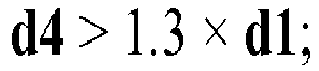
- In an embodiment 36 of the container holding device according to the present invention, the container holding device is designed according to its embodiment 23, wherein the container holding device is a vial nest designated to accommodate vials with a size designation "50R" according to DIN EN ISO 8362-1:2016-06 and wherein the container holding device comprises 10 to 30 vial, preferably 12 to 25 vials and even more preferably 15 to 20 vials that are held in position p1.
- In an embodiment 37 of the container holding device according to the present invention, the container holding device is designed according to its embodiment 36, wherein the diameter of the holes (d4) in the base plate is in the range from 20 to 35 mm, preferably in the range from 22 to 30 mm and more preferably in the range from 24 to 26 mm.
- In an embodiment 38 of the container holding device according to the present invention, the container holding device is designed according to its embodiment 32 or 33, wherein

- In an embodiment 39 of the container holding device according to the present invention, the container holding device is designed according to its embodiments 36 to 38, wherein d4 < d3 and wherein

- In an embodiment 40 of the container holding device according to the present invention, the container holding device is designed according to its embodiment 23, wherein the container holding device is a vial nest designated to accommodate vials with a size designation "100R" according to DIN EN ISO 8362-1:2016-06 and wherein the container holding device comprises 8 to 20 vial, preferably 10 to 18 vials and even more preferably 12 to 15 vials that are held in position p1.
- In an embodiment 41 of the container holding device according to the present invention, the container holding device is designed according to its embodiment 40, wherein the diameter of the holes (d4) in the base plate is in the range from 20 to 35 mm, preferably in the range from 22 to 30 mm and more preferably in the range from 24 to 26 mm.
- In an embodiment 42 of the container holding device according to the present invention, the container holding device is designed according to its embodiment 40 or 41, wherein

- In an embodiment 43 of the container holding device according to the present invention, the container holding device is designed according to anyone of its embodiments 40 to 42, wherein d4 < d3 and wherein

- A contribution to solving at least one of the objects according to the invention is also made by an embodiment 1 of a kit, comprising
- A) the container holding device according to anyone of its embodiments 23 to 43;
- B) a closure cup holding device that holds one or more closure systems, wherein the arrangement of the closure systems in the closure system holding device corresponds to the arrangement of the containers in the container holding device.
- In an embodiment 2 of the kit according to the present invention, the kit is designed according to its embodiment 1, wherein the closure cup holding device comprises a base plate having an upper surface and a bottom surface, and closure system holding elements that are located at the upper surface or the bottom surface of the base plate, wherein the closure system holding elements are adapted and arranged such that, when the container holding device and the closure system holding device are pressed together in order to close the containers in the container holding device with the closure systems in the closure system holding device, the holding elements of the container holding device are pushed away from the central symmetry axis Laxis by the approaching closure system holding elements.
- In an embodiment 3 of the kit according to the present invention, the kit is designed according to its embodiment 1, wherein the closure systems in the closure system holding device have an outer diameter d5 such that, when the container holding device and the closure system holding device are pressed together in order to close the containers in the container holding device with the closure systems in the closure cup holding device, the holding elements of the container holding device are pushed away from the central symmetry axis Laxis by the approaching closure system.
- In an embodiment 4 of the kit according to the present invention, the kits is designed according to anyone of its embodiments 1 to 3, wherein the closure system comprises an elastomeric stopper and a closure cap. Such a closure system is, for example, disclosed in
US 2012/0248057 A1 or inWO 2015/023924 A1 . Also suitable in this context are cap systems such as Daikyo Plascap® and LyoSeal® (West Pharmaceutical Services, Inc., USA) or RayDyLyo® (ARaymondlife SASU, France), arranged in a suitable nest. - In an embodiment 5 of the kit according to the present invention, the kit is designed according to anyone of its embodiments 1 to 4, wherein the kit further comprises
C) a transport and packaging container that accommodates the container holding device. - A contribution to solving at least one of the objects according to the invention is also made by an embodiment 1 of a process for producing closed containers, comprising the steps of
- I) providing a container holding device according to anyone of its embodiments 23 to 43 or a kit according to anyone of its embodiments 1 to 5, wherein one or more containers having an opening at the top edge of the top region are hanging in position p1 in the container holding device;
- II) bringing one or more of the containers from position p1 into position p2;
- III) imposing the top region of the container with a closure system.
- In an embodiment 2 of the process for producing closed containers according to the present invention, the process is designed according to its embodiment 1, wherein the container, before the top region of the container is imposed with the closure system, is closed with a stopper at least a part of which is introduced into the top region of the container.
- In an embodiment 3 of the process for producing closed containers according to the present invention, the process is designed according to its embodiment 1, wherein in process step III) a closure system is used that comprises an elastomeric stopper and a closure cap and wherein, if the top region of the container is imposed with the closure system, at least a part of the elastomeric stopper is introduced into the top region of the container. Suitable cap systems are those that have been described above in connection with the kit according to the present invention.
- In an embodiment 4 of the process for producing closed containers according to the present invention, the process is designed according to anyone of its embodiment 1 to 3, wherein the closure system is arranged in a closure system holding device as defined in embodiments 2 or 3 of the kit according to the present invention.
- In an embodiment 5 of the process for producing closed containers according to the present invention, the process is designed according to its embodiment 4, wherein imposing the top region of the container with a closure system in process step III) is accomplished by pressing together the container holding device and the closure system holding device, and wherein the holding elements of the container holding device are pushed away from the central symmetry axis Laxis by the approaching closure system and/or by the approaching closure system holding elements.
- In an embodiment 6 of the process for producing closed containers according to the present invention, the process is designed according to anyone of its embodiment 1 to 5, the process further comprising the step of
IV) removing the closed container from the container holding device by moving the closed container downwards or by pulling the container holding device upwards. - A contribution to solving at least one of the objects according to the invention is also made by the use of the container holding device according to anyone of its embodiments 1 to 43 for producing closed containers.
- Unless otherwise specified in the description or the particular figure:
- Figure 1A
- shows a part of a container holding device 100 (i. a. the area around a single hole 107) according to the present invention in a cross-sectional side view;
- Figure 1B
- shows in a top view a
container holding device 100 according to the present invention - Figure 2
- shows in a cross-sectional view the regions of a
container 101 that can be held in thecontainer holding device 100 according to the present invention; - Figure 3
- shows in a cross-sectional view the way in which a
container 101 is held in position p1 in acontainer holding device 100 according to the present invention; - Figure 4
- shows in a cross-sectional view the way in which a
container 101 is held in position p2 in acontainer holding device 100 according to the present invention; - Figure 5
- shows the advantage of an inclined arrangement of the holding
elements 108 on theunderside 106b of thebase plate 106; - Figure 6
- shows in a cross-sectional view how the holding
elements 108 are pushed away from the central symmetry axis Laxis if the top region of the container is imposed withclosure system 111 having a diameter d5; - Figure 7
- shows in a cross-sectional view how the
containers 101 in acontainer holding device 100 according to the present invention can be closed withclosure systems 111 that are held in a closuresystem holding device 114. -
Figure 1 shows a part of a container holding device 100 (i. a. the area around a single hole 107) according to the present invention in a cross-sectional side view according to the present invention in a cross-sectional side view. As can be seen infigure 1A , thecontainer holding device 100 according to the present invention comprises abase plate 106 having anupper surface 106a and abottom surface 106b, wherein thebase plate 106 comprises one ormore holes 107, eachhole 107 extending from theupper surface 106a to thebottom surface 106b and having a central symmetry axis Laxis orthogonal to said base plate 106 (see, for example,fig. 3 ). Thecontainer holding device 100 further comprises two ormore holding elements 108 that are located around eachhole 107 beneath thebottom surface 106b of thebase plate 106, wherein the holding elements of the holdingdevice 100 shown infigure 1A are designed in the form of clips. As can be seen infigure 1A , one significant difference to the vial nest known from the prior art is that the holdingelements 108 are located at thebottom surface 106b of thebase plate 106. Thevials 101 are thus hanging beneath thebase plate 106. As can be seen infigure 1B , theholes 107 can be arranged in a regular arrangement of rows and columns distributed on thebase plate 106, wherein the rows and columns are arranged regularly offset from each other and form a recurring arrangement. This regular arrangement is advantageous for automated treatment of thecontainers 101. In thedevice 100 shown infigure 1B threeclips 108 can be arranged at regular intervals along a circle around theindividual holes 107 on theunderside 106b of thebase plate 106, but it is also possible to arrange two, four or even more clips 108. Theclips 108 shown infigure 1A are designed in the form of a flexible holding arm that comprises a holdingnose 108a that is located at the bottom part of the flexible holding arm and that is adapted and arranged to hold acontainer 101 at thebottom edge 102b of thetop region 102, i. e. beneath the rolled edge (as shown infigure 3 ). -
Figure 2 shows in a cross-sectional view the regions of atypical container 101 that can be held in thecontainer holding device 100 according to the present invention, wherein thecontainer 101 is in the form of a vial. Thecontainer 101 comprises atop region 102 with atop edge 102a, abottom edge 102b and an outer diameter d1, a neck region 103 having an outer diameter d2 < d1, ashoulder region 104 and abody region 105 with an outer diameter d3 > d1. As shown infigure 2 , thetop region 102 of thecontainer 101 is usually designed in the form of a rolled edge. - As a material for the
container 101 to be held in thecontainer holding device 100 according to the present invention any material can be selected which the person skilled in the art would consider suitable for that purpose. Pharmaceutical containers made from tubular glass are commercially available in a range of different sizes with dimensions according to the DIN EN ISO 8362-1:2016-06 standard. Molded glass vials are commercially available in a range of different sizes with dimensions according to the DIN/ ISO 8362-4 standard. - Glass has traditionally been the only choice for container material but problems with glass breakage, delamination, particulates due to glass-on-glass collisions, and stability of some products resulted in development and usage of suitable polymeric materials. One example of such polymeric material is TOPAS® cyclic olefin polymer. Vials made of polymeric materials are commercially available in size ranges and dimensions that typically closely mimic those of glass vials. Polymeric materials are significantly less scratch resistant than glass and existing aseptic processing equipment has not been redesigned to mitigate the risks of scratching. Scratched surfaces of containers are a serious concern for the perceived quality of the product, but also severely limits the inspection of the containers for particulates. Such inspection is typically a regulated requirement for good manufacturing practice. Processing of vials in the
container holding device 100 according to the present invention is thus an effective solution to prevent scratching of vials such as typically occurs during singulated handling of vials or during simultaneous handling of rows of vials. These devices are particularly well suited for processing of polymeric vials but may be used equally well for processing of glass vials. -
Figure 3 shows in a cross-sectional view the way in which acontainer 101 is held in position p1 in acontainer holding device 100 according to the present invention, whereasfigure 6 shows in a cross-sectional view the way in which acontainer 101 is held in position p2. As can be seen, the holdingelements 108 are adapted and arranged to contact the outer surface of acontainer 101 that is placed into thecontainer holding device 100 at thebottom edge 102b of the top region 102 (in thevial 101 shown infigure 3 the holdingelements 108 hold thevial 101 below the lower edge of the rolled edge), such that the container is hanging in thecontainer holding device 100 in the first position p1 in which the holdingelements 108 do not exert any force on the outer surface of thecontainer 101 that is, with respect to said central symmetry axis Laxis , radial. The holdingelements 108 thus do not press against the outer surface of the neck region 103 of acontainer 101 and as a consequence thecontainers 101 rest loosely with the bottom side of the rolled edge laying on the holding elements 108 (to be more precisely, with thebottom side 102b of the rollededge 102 laying on the holdingnose 108b of the holding elements 108). Thus, holdingelements 108 are preferably adapted and arranged in such a way that they do not increase the force that is necessary to move the container from the first position p1 to the second position p2 along the path x (seefigures 3 and4 ) In the second position p2 the holdingelements 108 contact the outer surface of thecontainer 101 in theshoulder region 104 of thecontainer 101, thereby stabilizing thecontainer 101 if thecontainer 101 is raised upwards in thecontainer holding device 100 towards the second position p2. Raising thecontainer 101 form the first position p1 into the second position p2 can, for example, be accomplished by moving thebase plate 106 downwards or - as shown infigures 3 and4 - by raising asubstrate 113 upwards onto which thecontainers 101 are placed (such as a table of the pharmaceutical filling machine). - As can also be seen in
figures 3 and4 , the diameter d4 of theholes 107 in thebase plate 106 does not have to be as large as the outer diameter d3 of thecontainers 101 in thebody region 105 of the containers as the containers are hanging beneath thebase plate 106. It is, however, preferred that the diameter d4 of theholes 107 in thebase plate 106 has at least the size of the diameter d1 of thecontainer 101 in the top region (i. e. the diameter of the rolled edge) so that thecontainers 101 protrude with thetop region 102 of the container beyond theupper surface 106a of thebase plate 106 when they are lifted from position p1 into position p2. This facilitates imposing thetop region 102 of thecontainers 101 with a closure system. -
Figure 5 shows the advantage of an inclined arrangement of the holdingelements 108 on theunderside 106b of thebase plate 106. As shown in that figure, the holdingelements 108, which again are designed in the form ofclips 108, are arranged obliquely below thebase plate 106 so that theclips 108, when anobject 109, that has the same diameter or almost the same diameter as thehole 107, such as a closure system (seefigure 6 ) or the holding elements of a closure system holding device (seefigure 7 ), is introduced into thehole 107 from theupper surface 106a of thebase plate 106, are pushed away from the central symmetry axis Laxis of theholes 107 by the approachingobject 109. Such an arrangement can be realized by means ofclips 108 that comprise a substantially planeinner surface 108b that is directed towards the central symmetry axis Laxis of theholes 107, wherein astraight line 110 that is tangentially applied to theinner surface 108b and that runs in the same plane as the central symmetry axis Laxis of theholes 107 includes an angle α with the central symmetry axis Laxis of theholes 107. Pushing away theclips 108 from the central symmetry axis Laxis of theholes 107 facilitates pulling thecontainers 101 downwards out of thecontainer holding device 101 or pulling thecontainer holding device 100 upwards, for example after closing thecontainers 101 with a closure system. -
Figure 6 shows in a cross-sectional view how the holdingelements 108 are pushed away from the central symmetry axis Laxis if thetop region 102 of thecontainer 101 is imposed with closure system having a diameter d5. Preferably, the closure systems are present in the form of a closuresystem holding device 114 as shown infigure 7 . As the diameter of the closure system shown infigure 6 is larger than the distance of theclips 108 immediately beneath thebase plate 106, the holdingelements 108 of thecontainer holding device 100 are pushed away from the central symmetry axis Laxis by the approaching closure system. As also shown infigure 6 , the closure system preferably comprises aclosure cap 111 and a flexibleintegrated stopper 112. A part of theflexible stopper 112 is introduced into thetop region 102 of thecontainer 101 in order to close thecontainer 101 at the open end. -
Figure 7 shows in a cross-sectional view how thecontainers 101 in acontainer holding device 100 according to the present invention can be closed with closure systems that are held in a closuresystem holding device 114. As can be seen infigure 7 , the closuresystem holding device 114 comprises abase plate 115 having anupper surface 115a and abottom surface 115b, and closuresystem holding elements 116 that are located at thebottom surface 115b of thebase plate 115 and that are also preferably designed in the form of flexible holding arms. The closuresystem holding elements 116 are adapted and arranged so that, when thecontainer holding device 100 and the closuresystem holding device 114 are pressed together (i. e. if the closuresystem holding device 114 is moved downwards in the direction of the two arrows shown infigure 7 ) in order to close thecontainers 101 in thecontainer holding device 100 with the closure systems in the closuresystem holding device 114, the holdingelements 108 of thecontainer holding device 100 are pushed away from the central symmetry axis Laxis by the approaching closure system holding elements 116 (not shown infigure 7 ). Pushing away theclips 108 from the central symmetry axis Laxis of theholes 107 facilitates pulling thecontainer holding device 100 upwards after closing thecontainers 101 with the closure system, wherein both nests (i. e. thecontainer holding device 100 and the closure system holding device 114) can simultaneously be pulled away to the same side. -
- 100
- Container holding device
- 101
- container, preferably a vial
- 102
- top region of the
container 101, preferably in the form of a rolled edge - 102a
- top edge of the
top region 102 - 102b
- bottom edge of the
top region 102 - 103
- neck region of the
container 101 - 104
- shoulder region of the
container 101 - 105
- body region of the
container 101 - 106
- base plate
- 106a
- upper surface of the
base plate 106 - 106b
- bottom surface of the
base plate 106 - 107
- hole
- 108
- holding elements, preferably in the form of clips
- 108a
- holding nose located at the lower portion of the clips
- 108b
- inner surface of the
clips 108 - 109
- object
- 110
- straight line that is tangentially applied to the
inner surface 108b - 111
- closure cap
- 112
- flexible stopper
- 113
- substrate
- 114
- closure system holding device
- 115
- base plate of the closure
system holding device 114 - 115a
- upper surface of the
base plate 115 - 115b
- bottom surface of the
base plate 115 - 116
- closure system holding elements
Claims (15)
- A container holding device (100) for holding one or more containers (101), each container (101) comprising a top region (102) with a top edge (102a), a bottom edge (102a) and an outer diameter d1, a neck region (103) having an outer diameter d2 < d1, a shoulder region (104) and a body region (105) with an outer diameter d3 > d1, wherein the container holding device (100) comprises- a base plate (106) having an upper surface (106a) and a bottom surface (106b), wherein the base plate (106) comprises one or more holes (107), each hole (107) extending from the upper surface (106a) to the bottom surface (106b) and having a central symmetry axis Laxis orthogonal to said base plate (106);- two or more holding elements (108) that are located around each hole (107) beneath the bottom surface (106b) of the base plate (106);wherein the holding elements (108) are adapted and arrangedi) to contact the outer surface of a container (101) that is placed into the container holding device (100) at the bottom edge (102b) of the top region (102), such that the container is hanging in the container holding device (100) in a first position p1 in which the holding elements (108) preferably do not exert any force on the outer surface of the container (101) that is, with respect to said central symmetry axis Laxis, radial;
andii) to contact the outer surface of the container (101) in the shoulder region (104) of the container (101), thereby stabilizing the container (101) if the container (101) is raised upwards in the container holding device (100) towards second position p2. - The container holding device (100) according to claim 1, wherein the container (101) is selected from the group consisting of a vial, a vartridge, an ampule, a cartridge or a syringe.
- The container holding device (100) according to claim 1 or 2, wherein two, three, four or more holding elements (108) are arranged along a circle around each hole (107).
- The container holding device (100) according to anyone of claims 1 to 3, wherein the holding elements (108) are designed in the form of clips (108) that arranged obliquely below the base plate (106) so that the clips, when an object (109) that has the same or almost the same diameter as the hole (107) is introduced into the hole (107) from the upper surface (106a) of the base plate (106), are pushed away from the central symmetry axis Laxis of the holes (107) by the approaching object (109).
- The container holding device according to claim 4, wherein the clips (108) comprise a substantially plane inner surface (108b) that is directed towards the central symmetry axis Laxis of the holes (107), wherein a straight line (110) that is tangentially applied to the inner surface (108b) and that runs in the same plane as the central symmetry axis Laxis of the holes (107) includes an angle α with the central symmetry axis Laxis of the holes (107).
- The container according to claim 5, wherein α is in the range from 1 to 45 degree.
- The container holding device (100) according to anyone of claims 1 to 6, wherein the holes (107) have a diameter d4 < d3.
- The container holding device (100) according to anyone of claims 1 to 7, wherein the holes (107) have a diameter d4 > d1.
- The container holding device (100) according to anyone of claim 1 to 8, wherein the container holding device (100) further comprises one or more containers (101) that are hanging in position p1.
- A kit, comprisingA) the container holding device (100) according to claim 9;B) a closure system holding device (114) that holds one or more closure systems, preferably one or more closure systems comprising a closure cap (111) and an integrated flexible stopper (112), wherein the arrangement of the closure systems (111) in the closure system holding device (114) corresponds to the arrangement of the containers (101) in the container holding device (100).
- The kit according to claim 10, wherein the closure system holding device (114) comprises a base plate (115) having an upper surface (115a) and a bottom surface (115b), and closure system holding elements (116) that are located at the top surface (105a) or the bottom surface (115b) of the base plate (115), wherein the closure system holding elements (116) are adapted and arranged such that, when the container holding device (100) and the closure system holding device (114) are pressed together in order to close the containers (101) in the container holding device (100) with the closure systems (109) in the closure system holding device (114), the holding elements (108) of the container holding device (100) are pushed away from the central symmetry axis Laxis by the approaching closure system holding elements (116).
- The kit according to claim 10, wherein the closure systems (111) in the closure system holding device (114) have an outer diameter d5 such that, when the container holding device (100) and the closure system holding device (114) are pressed together in order to close the containers (101) in the container holding device (100) with the closure systems (111) in the closure system holding device (114), the holding elements (108) of the container holding device (100) are pushed away from the central symmetry axis Laxis by the approaching closure systems (111).
- A process for producing closed containers (101), comprising the steps ofI) providing a container holding device (100) according to claim 9 or a kit according to anyone of claims 10 to 12, wherein one or more containers (101) having an opening at the top edge (102a) of the top region (102) are hanging in position p1 in the container holding device (100);II) bringing one or more of the containers (101) from position p1 into position p2;III) imposing the top region (102) of the container (101) with a closure system, preferably with a closure system comprising a closure cap (111) and an integrated flexible stopper (112).
- The process according to claim 13, wherein the closure system (111) is arranged in a closure system holding device (114) as defined in any one of claims 10 to 12.
- Use of the container holding device (100) according to anyone of claims 1 to 9 for producing closed containers (101).
Priority Applications (4)
| Application Number | Priority Date | Filing Date | Title |
|---|---|---|---|
| EP19199683.4A EP3798142B1 (en) | 2019-09-25 | 2019-09-25 | Container holding device |
| US17/031,381 US11241361B2 (en) | 2019-09-25 | 2020-09-24 | Holding device for the flexible treatment of pharmaceutical packaging materials |
| CN202011018422.3A CN112550910B (en) | 2019-09-25 | 2020-09-24 | Holding device for flexible handling of pharmaceutical packaging materials |
| CN202022119613.0U CN213443868U (en) | 2019-09-25 | 2020-09-24 | Container holding device and kit |
Applications Claiming Priority (1)
| Application Number | Priority Date | Filing Date | Title |
|---|---|---|---|
| EP19199683.4A EP3798142B1 (en) | 2019-09-25 | 2019-09-25 | Container holding device |
Publications (2)
| Publication Number | Publication Date |
|---|---|
| EP3798142A1 true EP3798142A1 (en) | 2021-03-31 |
| EP3798142B1 EP3798142B1 (en) | 2024-05-01 |
Family
ID=68109108
Family Applications (1)
| Application Number | Title | Priority Date | Filing Date |
|---|---|---|---|
| EP19199683.4A Active EP3798142B1 (en) | 2019-09-25 | 2019-09-25 | Container holding device |
Country Status (3)
| Country | Link |
|---|---|
| US (1) | US11241361B2 (en) |
| EP (1) | EP3798142B1 (en) |
| CN (2) | CN213443868U (en) |
Families Citing this family (4)
| Publication number | Priority date | Publication date | Assignee | Title |
|---|---|---|---|---|
| US12515832B2 (en) * | 2013-08-16 | 2026-01-06 | Vanrx Pharmasystems Inc. | Method, device and system for filling pharmaceutical containers |
| EP3798142B1 (en) * | 2019-09-25 | 2024-05-01 | SCHOTT Pharma AG & Co. KGaA | Container holding device |
| EP4635529A1 (en) * | 2024-04-15 | 2025-10-22 | SCHOTT Pharma Schweiz AG | Nest with movable protrusions for pharmaceutical containers |
| CN119329889A (en) * | 2024-10-31 | 2025-01-21 | 江苏乐聚医药科技有限公司 | A nesting board |
Citations (5)
| Publication number | Priority date | Publication date | Assignee | Title |
|---|---|---|---|---|
| US20050133386A1 (en) * | 2003-12-18 | 2005-06-23 | Rehrig Pacific Company | Bottle carrier |
| US20120248057A1 (en) | 2011-04-04 | 2012-10-04 | Genesis Packaging Technologies | Cap systems and methods for sealing pharmaceutical vials |
| DE102012110339A1 (en) | 2012-05-03 | 2013-11-07 | Schott Ag | Holding structure for simultaneously holding a plurality of medical or pharmaceutical containers as well as transport or packaging containers with self and method for treating such containers |
| US20140027332A1 (en) * | 2012-05-03 | 2014-01-30 | Schott Ag | Holding structure for simultaneously holding a plurality of containers for medical, pharmaceutical or cosmetic applications and transport or packaging container with holding structure |
| WO2015023924A2 (en) | 2013-08-16 | 2015-02-19 | Vanrx Pharmasystems Inc. | Method, device and system for filling pharmaceutical containers |
Family Cites Families (8)
| Publication number | Priority date | Publication date | Assignee | Title |
|---|---|---|---|---|
| US6325210B1 (en) * | 1999-02-04 | 2001-12-04 | Douglass C. Henry, Jr. | Wine bottle package |
| WO2011138788A1 (en) * | 2010-05-04 | 2011-11-10 | Impackit Ltd. | Stacking and securing system for containers |
| CN105050636B (en) * | 2012-11-12 | 2017-11-03 | 肖特股份有限公司 | Process or treatment method and apparatus for containers of substances for medical, pharmaceutical or cosmetic applications |
| DE102013111600B4 (en) * | 2013-10-21 | 2018-04-05 | Schott Ag | Support structure for holding containers for substances for medical, pharmaceutical or cosmetic applications, as well as transport and packaging containers with the same |
| FR3098504B1 (en) * | 2019-07-09 | 2021-06-04 | A Raymond Et Cie | locking cap for neck container |
| EP3791906B1 (en) * | 2019-09-11 | 2024-03-27 | SCHOTT Pharma Schweiz AG | Charge device having a positioning means and a process for closing receptacles with venting |
| EP3798142B1 (en) * | 2019-09-25 | 2024-05-01 | SCHOTT Pharma AG & Co. KGaA | Container holding device |
| EP3851089A1 (en) * | 2020-01-20 | 2021-07-21 | SCHOTT Schweiz AG | Holding device for holding a plurality of containers in a positive fit which is established by a displacement movement |
-
2019
- 2019-09-25 EP EP19199683.4A patent/EP3798142B1/en active Active
-
2020
- 2020-09-24 CN CN202022119613.0U patent/CN213443868U/en active Active
- 2020-09-24 CN CN202011018422.3A patent/CN112550910B/en active Active
- 2020-09-24 US US17/031,381 patent/US11241361B2/en active Active
Patent Citations (6)
| Publication number | Priority date | Publication date | Assignee | Title |
|---|---|---|---|---|
| US20050133386A1 (en) * | 2003-12-18 | 2005-06-23 | Rehrig Pacific Company | Bottle carrier |
| US20120248057A1 (en) | 2011-04-04 | 2012-10-04 | Genesis Packaging Technologies | Cap systems and methods for sealing pharmaceutical vials |
| DE102012110339A1 (en) | 2012-05-03 | 2013-11-07 | Schott Ag | Holding structure for simultaneously holding a plurality of medical or pharmaceutical containers as well as transport or packaging containers with self and method for treating such containers |
| US20140027332A1 (en) * | 2012-05-03 | 2014-01-30 | Schott Ag | Holding structure for simultaneously holding a plurality of containers for medical, pharmaceutical or cosmetic applications and transport or packaging container with holding structure |
| WO2015023924A2 (en) | 2013-08-16 | 2015-02-19 | Vanrx Pharmasystems Inc. | Method, device and system for filling pharmaceutical containers |
| US20190135462A1 (en) * | 2013-08-16 | 2019-05-09 | Vanrx Pharmasystems Inc. | Method for filling pharmaceutical containers |
Also Published As
| Publication number | Publication date |
|---|---|
| US11241361B2 (en) | 2022-02-08 |
| US20210085562A1 (en) | 2021-03-25 |
| EP3798142B1 (en) | 2024-05-01 |
| CN213443868U (en) | 2021-06-15 |
| CN112550910B (en) | 2025-07-04 |
| CN112550910A (en) | 2021-03-26 |
Similar Documents
| Publication | Publication Date | Title |
|---|---|---|
| US11241361B2 (en) | Holding device for the flexible treatment of pharmaceutical packaging materials | |
| US11498709B2 (en) | Method for closing cartridges, supporting structure for supporting cartridge closures and transport or packaging container | |
| US12172792B2 (en) | Closure nest for releasably retaining a plurality of pharmaceutical container closures | |
| DK2868593T3 (en) | Holding structure for simultaneous retention of several containers for substances for medical, pharmaceutical or cosmetic applications, as well as transport and packaging containers with the same and method | |
| WO2018020505A1 (en) | Method for closing vials, supporting structure for vial stopper members and transport or packaging container | |
| CN105050636B (en) | Process or treatment method and apparatus for containers of substances for medical, pharmaceutical or cosmetic applications | |
| US11548687B2 (en) | Transport unit and packaging structure for transporting and storing a plurality of containers for substances for pharmaceutical, medical or cosmetic uses | |
| US11464705B2 (en) | Holding structure for concurrently holding a plurality of containers for substances for pharmaceutical, medical or cosmetic applications, transport structure and transport or packaging container comprising the same | |
| CN102470207A (en) | Packaging structure for pharmaceutical containers | |
| US20260042557A1 (en) | Method, device and system for filling pharmaceutical containers |
Legal Events
| Date | Code | Title | Description |
|---|---|---|---|
| STAA | Information on the status of an ep patent application or granted ep patent |
Free format text: STATUS: EXAMINATION IS IN PROGRESS |
|
| PUAI | Public reference made under article 153(3) epc to a published international application that has entered the european phase |
Free format text: ORIGINAL CODE: 0009012 |
|
| 17P | Request for examination filed |
Effective date: 20190925 |
|
| AK | Designated contracting states |
Kind code of ref document: A1 Designated state(s): AL AT BE BG CH CY CZ DE DK EE ES FI FR GB GR HR HU IE IS IT LI LT LU LV MC MK MT NL NO PL PT RO RS SE SI SK SM TR |
|
| AX | Request for extension of the european patent |
Extension state: BA ME |
|
| RBV | Designated contracting states (corrected) |
Designated state(s): AL AT BE BG CH CY CZ DE DK EE ES FI FR GB GR HR HU IE IS IT LI LT LU LV MC MK MT NL NO PL PT RO RS SE SI SK SM TR |
|
| RAP3 | Party data changed (applicant data changed or rights of an application transferred) |
Owner name: SCHOTT AG |
|
| RAP1 | Party data changed (applicant data changed or rights of an application transferred) |
Owner name: SCHOTT PHARMA AG & CO. KGAA |
|
| P01 | Opt-out of the competence of the unified patent court (upc) registered |
Effective date: 20230512 |
|
| REG | Reference to a national code |
Ref country code: DE Ref legal event code: R079 Free format text: PREVIOUS MAIN CLASS: B65B0007000000 Ipc: B65D0025100000 Ref country code: DE Ref legal event code: R079 Ref document number: 602019051255 Country of ref document: DE Free format text: PREVIOUS MAIN CLASS: B65B0007000000 Ipc: B65D0025100000 |
|
| GRAP | Despatch of communication of intention to grant a patent |
Free format text: ORIGINAL CODE: EPIDOSNIGR1 |
|
| STAA | Information on the status of an ep patent application or granted ep patent |
Free format text: STATUS: GRANT OF PATENT IS INTENDED |
|
| RIC1 | Information provided on ipc code assigned before grant |
Ipc: B01L 9/00 20060101ALI20231130BHEP Ipc: B65D 1/02 20060101ALI20231130BHEP Ipc: B65B 7/28 20060101ALI20231130BHEP Ipc: B65B 7/16 20060101ALI20231130BHEP Ipc: B65B 7/00 20060101ALI20231130BHEP Ipc: B65D 25/10 20060101AFI20231130BHEP |
|
| INTG | Intention to grant announced |
Effective date: 20231220 |
|
| GRAS | Grant fee paid |
Free format text: ORIGINAL CODE: EPIDOSNIGR3 |
|
| GRAA | (expected) grant |
Free format text: ORIGINAL CODE: 0009210 |
|
| STAA | Information on the status of an ep patent application or granted ep patent |
Free format text: STATUS: THE PATENT HAS BEEN GRANTED |
|
| AK | Designated contracting states |
Kind code of ref document: B1 Designated state(s): AL AT BE BG CH CY CZ DE DK EE ES FI FR GB GR HR HU IE IS IT LI LT LU LV MC MK MT NL NO PL PT RO RS SE SI SK SM TR |
|
| REG | Reference to a national code |
Ref country code: GB Ref legal event code: FG4D |
|
| REG | Reference to a national code |
Ref country code: CH Ref legal event code: EP |
|
| REG | Reference to a national code |
Ref country code: IE Ref legal event code: FG4D |
|
| REG | Reference to a national code |
Ref country code: DE Ref legal event code: R096 Ref document number: 602019051255 Country of ref document: DE |
|
| REG | Reference to a national code |
Ref country code: LT Ref legal event code: MG9D |
|
| REG | Reference to a national code |
Ref country code: NL Ref legal event code: MP Effective date: 20240501 |
|
| PG25 | Lapsed in a contracting state [announced via postgrant information from national office to epo] |
Ref country code: IS Free format text: LAPSE BECAUSE OF FAILURE TO SUBMIT A TRANSLATION OF THE DESCRIPTION OR TO PAY THE FEE WITHIN THE PRESCRIBED TIME-LIMIT Effective date: 20240901 |
|
| PG25 | Lapsed in a contracting state [announced via postgrant information from national office to epo] |
Ref country code: BG Free format text: LAPSE BECAUSE OF FAILURE TO SUBMIT A TRANSLATION OF THE DESCRIPTION OR TO PAY THE FEE WITHIN THE PRESCRIBED TIME-LIMIT Effective date: 20240501 |
|
| PG25 | Lapsed in a contracting state [announced via postgrant information from national office to epo] |
Ref country code: FI Free format text: LAPSE BECAUSE OF FAILURE TO SUBMIT A TRANSLATION OF THE DESCRIPTION OR TO PAY THE FEE WITHIN THE PRESCRIBED TIME-LIMIT Effective date: 20240501 Ref country code: HR Free format text: LAPSE BECAUSE OF FAILURE TO SUBMIT A TRANSLATION OF THE DESCRIPTION OR TO PAY THE FEE WITHIN THE PRESCRIBED TIME-LIMIT Effective date: 20240501 |
|
| PG25 | Lapsed in a contracting state [announced via postgrant information from national office to epo] |
Ref country code: GR Free format text: LAPSE BECAUSE OF FAILURE TO SUBMIT A TRANSLATION OF THE DESCRIPTION OR TO PAY THE FEE WITHIN THE PRESCRIBED TIME-LIMIT Effective date: 20240802 |
|
| PG25 | Lapsed in a contracting state [announced via postgrant information from national office to epo] |
Ref country code: PT Free format text: LAPSE BECAUSE OF FAILURE TO SUBMIT A TRANSLATION OF THE DESCRIPTION OR TO PAY THE FEE WITHIN THE PRESCRIBED TIME-LIMIT Effective date: 20240902 |
|
| REG | Reference to a national code |
Ref country code: AT Ref legal event code: MK05 Ref document number: 1682072 Country of ref document: AT Kind code of ref document: T Effective date: 20240501 |
|
| PG25 | Lapsed in a contracting state [announced via postgrant information from national office to epo] |
Ref country code: NL Free format text: LAPSE BECAUSE OF FAILURE TO SUBMIT A TRANSLATION OF THE DESCRIPTION OR TO PAY THE FEE WITHIN THE PRESCRIBED TIME-LIMIT Effective date: 20240501 |
|
| PG25 | Lapsed in a contracting state [announced via postgrant information from national office to epo] |
Ref country code: ES Free format text: LAPSE BECAUSE OF FAILURE TO SUBMIT A TRANSLATION OF THE DESCRIPTION OR TO PAY THE FEE WITHIN THE PRESCRIBED TIME-LIMIT Effective date: 20240501 |
|
| PG25 | Lapsed in a contracting state [announced via postgrant information from national office to epo] |
Ref country code: AT Free format text: LAPSE BECAUSE OF FAILURE TO SUBMIT A TRANSLATION OF THE DESCRIPTION OR TO PAY THE FEE WITHIN THE PRESCRIBED TIME-LIMIT Effective date: 20240501 |
|
| PG25 | Lapsed in a contracting state [announced via postgrant information from national office to epo] |
Ref country code: PL Free format text: LAPSE BECAUSE OF FAILURE TO SUBMIT A TRANSLATION OF THE DESCRIPTION OR TO PAY THE FEE WITHIN THE PRESCRIBED TIME-LIMIT Effective date: 20240501 |
|
| PG25 | Lapsed in a contracting state [announced via postgrant information from national office to epo] |
Ref country code: LV Free format text: LAPSE BECAUSE OF FAILURE TO SUBMIT A TRANSLATION OF THE DESCRIPTION OR TO PAY THE FEE WITHIN THE PRESCRIBED TIME-LIMIT Effective date: 20240501 |
|
| PG25 | Lapsed in a contracting state [announced via postgrant information from national office to epo] |
Ref country code: PT Free format text: LAPSE BECAUSE OF FAILURE TO SUBMIT A TRANSLATION OF THE DESCRIPTION OR TO PAY THE FEE WITHIN THE PRESCRIBED TIME-LIMIT Effective date: 20240902 Ref country code: PL Free format text: LAPSE BECAUSE OF FAILURE TO SUBMIT A TRANSLATION OF THE DESCRIPTION OR TO PAY THE FEE WITHIN THE PRESCRIBED TIME-LIMIT Effective date: 20240501 Ref country code: NO Free format text: LAPSE BECAUSE OF FAILURE TO SUBMIT A TRANSLATION OF THE DESCRIPTION OR TO PAY THE FEE WITHIN THE PRESCRIBED TIME-LIMIT Effective date: 20240801 Ref country code: NL Free format text: LAPSE BECAUSE OF FAILURE TO SUBMIT A TRANSLATION OF THE DESCRIPTION OR TO PAY THE FEE WITHIN THE PRESCRIBED TIME-LIMIT Effective date: 20240501 Ref country code: LV Free format text: LAPSE BECAUSE OF FAILURE TO SUBMIT A TRANSLATION OF THE DESCRIPTION OR TO PAY THE FEE WITHIN THE PRESCRIBED TIME-LIMIT Effective date: 20240501 Ref country code: IS Free format text: LAPSE BECAUSE OF FAILURE TO SUBMIT A TRANSLATION OF THE DESCRIPTION OR TO PAY THE FEE WITHIN THE PRESCRIBED TIME-LIMIT Effective date: 20240901 Ref country code: HR Free format text: LAPSE BECAUSE OF FAILURE TO SUBMIT A TRANSLATION OF THE DESCRIPTION OR TO PAY THE FEE WITHIN THE PRESCRIBED TIME-LIMIT Effective date: 20240501 Ref country code: GR Free format text: LAPSE BECAUSE OF FAILURE TO SUBMIT A TRANSLATION OF THE DESCRIPTION OR TO PAY THE FEE WITHIN THE PRESCRIBED TIME-LIMIT Effective date: 20240802 Ref country code: FI Free format text: LAPSE BECAUSE OF FAILURE TO SUBMIT A TRANSLATION OF THE DESCRIPTION OR TO PAY THE FEE WITHIN THE PRESCRIBED TIME-LIMIT Effective date: 20240501 Ref country code: ES Free format text: LAPSE BECAUSE OF FAILURE TO SUBMIT A TRANSLATION OF THE DESCRIPTION OR TO PAY THE FEE WITHIN THE PRESCRIBED TIME-LIMIT Effective date: 20240501 Ref country code: BG Free format text: LAPSE BECAUSE OF FAILURE TO SUBMIT A TRANSLATION OF THE DESCRIPTION OR TO PAY THE FEE WITHIN THE PRESCRIBED TIME-LIMIT Effective date: 20240501 Ref country code: AT Free format text: LAPSE BECAUSE OF FAILURE TO SUBMIT A TRANSLATION OF THE DESCRIPTION OR TO PAY THE FEE WITHIN THE PRESCRIBED TIME-LIMIT Effective date: 20240501 Ref country code: RS Free format text: LAPSE BECAUSE OF FAILURE TO SUBMIT A TRANSLATION OF THE DESCRIPTION OR TO PAY THE FEE WITHIN THE PRESCRIBED TIME-LIMIT Effective date: 20240801 |
|
| PG25 | Lapsed in a contracting state [announced via postgrant information from national office to epo] |
Ref country code: DK Free format text: LAPSE BECAUSE OF FAILURE TO SUBMIT A TRANSLATION OF THE DESCRIPTION OR TO PAY THE FEE WITHIN THE PRESCRIBED TIME-LIMIT Effective date: 20240501 |
|
| PG25 | Lapsed in a contracting state [announced via postgrant information from national office to epo] |
Ref country code: EE Free format text: LAPSE BECAUSE OF FAILURE TO SUBMIT A TRANSLATION OF THE DESCRIPTION OR TO PAY THE FEE WITHIN THE PRESCRIBED TIME-LIMIT Effective date: 20240501 |
|
| PG25 | Lapsed in a contracting state [announced via postgrant information from national office to epo] |
Ref country code: CZ Free format text: LAPSE BECAUSE OF FAILURE TO SUBMIT A TRANSLATION OF THE DESCRIPTION OR TO PAY THE FEE WITHIN THE PRESCRIBED TIME-LIMIT Effective date: 20240501 |
|
| PG25 | Lapsed in a contracting state [announced via postgrant information from national office to epo] |
Ref country code: RO Free format text: LAPSE BECAUSE OF FAILURE TO SUBMIT A TRANSLATION OF THE DESCRIPTION OR TO PAY THE FEE WITHIN THE PRESCRIBED TIME-LIMIT Effective date: 20240501 Ref country code: SK Free format text: LAPSE BECAUSE OF FAILURE TO SUBMIT A TRANSLATION OF THE DESCRIPTION OR TO PAY THE FEE WITHIN THE PRESCRIBED TIME-LIMIT Effective date: 20240501 |
|
| PG25 | Lapsed in a contracting state [announced via postgrant information from national office to epo] |
Ref country code: SM Free format text: LAPSE BECAUSE OF FAILURE TO SUBMIT A TRANSLATION OF THE DESCRIPTION OR TO PAY THE FEE WITHIN THE PRESCRIBED TIME-LIMIT Effective date: 20240501 |
|
| PG25 | Lapsed in a contracting state [announced via postgrant information from national office to epo] |
Ref country code: SM Free format text: LAPSE BECAUSE OF FAILURE TO SUBMIT A TRANSLATION OF THE DESCRIPTION OR TO PAY THE FEE WITHIN THE PRESCRIBED TIME-LIMIT Effective date: 20240501 Ref country code: SK Free format text: LAPSE BECAUSE OF FAILURE TO SUBMIT A TRANSLATION OF THE DESCRIPTION OR TO PAY THE FEE WITHIN THE PRESCRIBED TIME-LIMIT Effective date: 20240501 Ref country code: RO Free format text: LAPSE BECAUSE OF FAILURE TO SUBMIT A TRANSLATION OF THE DESCRIPTION OR TO PAY THE FEE WITHIN THE PRESCRIBED TIME-LIMIT Effective date: 20240501 Ref country code: EE Free format text: LAPSE BECAUSE OF FAILURE TO SUBMIT A TRANSLATION OF THE DESCRIPTION OR TO PAY THE FEE WITHIN THE PRESCRIBED TIME-LIMIT Effective date: 20240501 Ref country code: DK Free format text: LAPSE BECAUSE OF FAILURE TO SUBMIT A TRANSLATION OF THE DESCRIPTION OR TO PAY THE FEE WITHIN THE PRESCRIBED TIME-LIMIT Effective date: 20240501 Ref country code: CZ Free format text: LAPSE BECAUSE OF FAILURE TO SUBMIT A TRANSLATION OF THE DESCRIPTION OR TO PAY THE FEE WITHIN THE PRESCRIBED TIME-LIMIT Effective date: 20240501 |
|
| REG | Reference to a national code |
Ref country code: DE Ref legal event code: R097 Ref document number: 602019051255 Country of ref document: DE |
|
| PLBE | No opposition filed within time limit |
Free format text: ORIGINAL CODE: 0009261 |
|
| STAA | Information on the status of an ep patent application or granted ep patent |
Free format text: STATUS: NO OPPOSITION FILED WITHIN TIME LIMIT |
|
| 26N | No opposition filed |
Effective date: 20250204 |
|
| PG25 | Lapsed in a contracting state [announced via postgrant information from national office to epo] |
Ref country code: SI Free format text: LAPSE BECAUSE OF FAILURE TO SUBMIT A TRANSLATION OF THE DESCRIPTION OR TO PAY THE FEE WITHIN THE PRESCRIBED TIME-LIMIT Effective date: 20240501 Ref country code: MC Free format text: LAPSE BECAUSE OF FAILURE TO SUBMIT A TRANSLATION OF THE DESCRIPTION OR TO PAY THE FEE WITHIN THE PRESCRIBED TIME-LIMIT Effective date: 20240501 |
|
| PG25 | Lapsed in a contracting state [announced via postgrant information from national office to epo] |
Ref country code: LU Free format text: LAPSE BECAUSE OF NON-PAYMENT OF DUE FEES Effective date: 20240925 |
|
| REG | Reference to a national code |
Ref country code: BE Ref legal event code: MM Effective date: 20240930 |
|
| PG25 | Lapsed in a contracting state [announced via postgrant information from national office to epo] |
Ref country code: BE Free format text: LAPSE BECAUSE OF NON-PAYMENT OF DUE FEES Effective date: 20240930 |
|
| PG25 | Lapsed in a contracting state [announced via postgrant information from national office to epo] |
Ref country code: IE Free format text: LAPSE BECAUSE OF NON-PAYMENT OF DUE FEES Effective date: 20240925 |
|
| PG25 | Lapsed in a contracting state [announced via postgrant information from national office to epo] |
Ref country code: SE Free format text: LAPSE BECAUSE OF FAILURE TO SUBMIT A TRANSLATION OF THE DESCRIPTION OR TO PAY THE FEE WITHIN THE PRESCRIBED TIME-LIMIT Effective date: 20240501 |
|
| REG | Reference to a national code |
Ref country code: CH Ref legal event code: U11 Free format text: ST27 STATUS EVENT CODE: U-0-0-U10-U11 (AS PROVIDED BY THE NATIONAL OFFICE) Effective date: 20251001 |
|
| PGFP | Annual fee paid to national office [announced via postgrant information from national office to epo] |
Ref country code: DE Payment date: 20250919 Year of fee payment: 7 |
|
| PGFP | Annual fee paid to national office [announced via postgrant information from national office to epo] |
Ref country code: IT Payment date: 20250923 Year of fee payment: 7 |
|
| PGFP | Annual fee paid to national office [announced via postgrant information from national office to epo] |
Ref country code: GB Payment date: 20250919 Year of fee payment: 7 |
|
| PGFP | Annual fee paid to national office [announced via postgrant information from national office to epo] |
Ref country code: FR Payment date: 20250922 Year of fee payment: 7 |
|
| PGFP | Annual fee paid to national office [announced via postgrant information from national office to epo] |
Ref country code: CH Payment date: 20251001 Year of fee payment: 7 |
|
| PG25 | Lapsed in a contracting state [announced via postgrant information from national office to epo] |
Ref country code: CY Free format text: LAPSE BECAUSE OF FAILURE TO SUBMIT A TRANSLATION OF THE DESCRIPTION OR TO PAY THE FEE WITHIN THE PRESCRIBED TIME-LIMIT; INVALID AB INITIO Effective date: 20190925 |
|
| PG25 | Lapsed in a contracting state [announced via postgrant information from national office to epo] |
Ref country code: HU Free format text: LAPSE BECAUSE OF FAILURE TO SUBMIT A TRANSLATION OF THE DESCRIPTION OR TO PAY THE FEE WITHIN THE PRESCRIBED TIME-LIMIT; INVALID AB INITIO Effective date: 20190925 |