EP3798029B1 - Suspension arrangement for a work vehicle - Google Patents
Suspension arrangement for a work vehicle Download PDFInfo
- Publication number
- EP3798029B1 EP3798029B1 EP20196602.5A EP20196602A EP3798029B1 EP 3798029 B1 EP3798029 B1 EP 3798029B1 EP 20196602 A EP20196602 A EP 20196602A EP 3798029 B1 EP3798029 B1 EP 3798029B1
- Authority
- EP
- European Patent Office
- Prior art keywords
- work vehicle
- contact
- vehicle according
- elastic block
- annular
- Prior art date
- Legal status (The legal status is an assumption and is not a legal conclusion. Google has not performed a legal analysis and makes no representation as to the accuracy of the status listed.)
- Active
Links
Images


Classifications
-
- B—PERFORMING OPERATIONS; TRANSPORTING
- B60—VEHICLES IN GENERAL
- B60G—VEHICLE SUSPENSION ARRANGEMENTS
- B60G99/00—Subject matter not provided for in other groups of this subclass
- B60G99/002—Suspension details of the suspension of the vehicle body on the vehicle chassis
-
- B—PERFORMING OPERATIONS; TRANSPORTING
- B60—VEHICLES IN GENERAL
- B60G—VEHICLE SUSPENSION ARRANGEMENTS
- B60G11/00—Resilient suspensions characterised by arrangement, location or kind of springs
- B60G11/22—Resilient suspensions characterised by arrangement, location or kind of springs having rubber springs only
-
- B—PERFORMING OPERATIONS; TRANSPORTING
- B62—LAND VEHICLES FOR TRAVELLING OTHERWISE THAN ON RAILS
- B62D—MOTOR VEHICLES; TRAILERS
- B62D33/00—Superstructures for load-carrying vehicles
- B62D33/06—Drivers' cabs
- B62D33/0604—Cabs insulated against vibrations or noise, e.g. with elastic suspension
-
- F—MECHANICAL ENGINEERING; LIGHTING; HEATING; WEAPONS; BLASTING
- F16—ENGINEERING ELEMENTS AND UNITS; GENERAL MEASURES FOR PRODUCING AND MAINTAINING EFFECTIVE FUNCTIONING OF MACHINES OR INSTALLATIONS; THERMAL INSULATION IN GENERAL
- F16F—SPRINGS; SHOCK-ABSORBERS; MEANS FOR DAMPING VIBRATION
- F16F7/00—Vibration-dampers; Shock-absorbers
- F16F7/10—Vibration-dampers; Shock-absorbers using inertia effect
- F16F7/104—Vibration-dampers; Shock-absorbers using inertia effect the inertia member being resiliently mounted
- F16F7/108—Vibration-dampers; Shock-absorbers using inertia effect the inertia member being resiliently mounted on plastics springs
-
- B—PERFORMING OPERATIONS; TRANSPORTING
- B60—VEHICLES IN GENERAL
- B60G—VEHICLE SUSPENSION ARRANGEMENTS
- B60G2202/00—Indexing codes relating to the type of spring, damper or actuator
- B60G2202/20—Type of damper
- B60G2202/25—Dynamic damper
-
- B—PERFORMING OPERATIONS; TRANSPORTING
- B60—VEHICLES IN GENERAL
- B60G—VEHICLE SUSPENSION ARRANGEMENTS
- B60G2204/00—Indexing codes related to suspensions per se or to auxiliary parts
- B60G2204/10—Mounting of suspension elements
- B60G2204/16—Mounting of vehicle body on chassis
- B60G2204/162—Cabins, e.g. for trucks, tractors
-
- B—PERFORMING OPERATIONS; TRANSPORTING
- B60—VEHICLES IN GENERAL
- B60G—VEHICLE SUSPENSION ARRANGEMENTS
- B60G2204/00—Indexing codes related to suspensions per se or to auxiliary parts
- B60G2204/40—Auxiliary suspension parts; Adjustment of suspensions
- B60G2204/41—Elastic mounts, e.g. bushings
-
- B—PERFORMING OPERATIONS; TRANSPORTING
- B60—VEHICLES IN GENERAL
- B60G—VEHICLE SUSPENSION ARRANGEMENTS
- B60G2206/00—Indexing codes related to the manufacturing of suspensions: constructional features, the materials used, procedures or tools
- B60G2206/01—Constructional features of suspension elements, e.g. arms, dampers, springs
- B60G2206/70—Materials used in suspensions
- B60G2206/72—Steel
-
- B—PERFORMING OPERATIONS; TRANSPORTING
- B60—VEHICLES IN GENERAL
- B60G—VEHICLE SUSPENSION ARRANGEMENTS
- B60G2206/00—Indexing codes related to the manufacturing of suspensions: constructional features, the materials used, procedures or tools
- B60G2206/01—Constructional features of suspension elements, e.g. arms, dampers, springs
- B60G2206/70—Materials used in suspensions
- B60G2206/73—Rubber; Elastomers
-
- B—PERFORMING OPERATIONS; TRANSPORTING
- B60—VEHICLES IN GENERAL
- B60G—VEHICLE SUSPENSION ARRANGEMENTS
- B60G2206/00—Indexing codes related to the manufacturing of suspensions: constructional features, the materials used, procedures or tools
- B60G2206/01—Constructional features of suspension elements, e.g. arms, dampers, springs
- B60G2206/80—Manufacturing procedures
- B60G2206/82—Joining
- B60G2206/8207—Joining by screwing
-
- B—PERFORMING OPERATIONS; TRANSPORTING
- B60—VEHICLES IN GENERAL
- B60G—VEHICLE SUSPENSION ARRANGEMENTS
- B60G2300/00—Indexing codes relating to the type of vehicle
- B60G2300/07—Off-road vehicles
-
- B—PERFORMING OPERATIONS; TRANSPORTING
- B60—VEHICLES IN GENERAL
- B60G—VEHICLE SUSPENSION ARRANGEMENTS
- B60G2300/00—Indexing codes relating to the type of vehicle
- B60G2300/08—Agricultural vehicles
Definitions
- the present invention concerns a work vehicle comprising a body and a cab, in particular a front suspension arrangement for a cab of a work vehicle such as a tractor.
- the motion of the cab of a vehicle with respect to the chassis thereof is an annoying movement for the comfort of the driver of the vehicle. Such inconvenience is even greater when the vehicle is an off-road vehicle, such as an agricultural vehicle.
- the engine/driveline of the vehicle transmits vibrations at a peculiar frequency that further increases the noise in the cab.
- non-suspended cabs comprise conventional silent-blocks, i.e. elastic elements, as connection with the vehicle body.
- conventional silent-blocks i.e. elastic elements
- FR2914901 discloses a vehicle with a cabin and body supported by a multiplicity of wheels; a cabin support supported by the vehicle body; an elastic element for supporting the cabin, disposed between the cabin and the cabin support; and a mass element attached to a plate-shaped element of the cabin.
- the document FR 2 914 901 discloses a work vehicle according to the preamble of claim 1.
- the documents US 6 017 073 , FR 2 801 655 , US 2008/143029 , US 4 445 662 and DE 12 90 830 B disclose other suspension arrangements.
- An aim of the present invention is to satisfy the above mentioned needs.
- Figures 1 to 3 show a suspension arrangement 1 interposed between a cab portion 2 and a body portion 3 of the vehicle.
- cab portion 2 and body portion 3 are substantially irrelevant with respect to the operation of the suspension arrangement 1 of the present invention and therefore their shape will be not described into detail.
- the only peculiar feature of such portions 2, 3 is that they define respective end plates 2a, 3a, faced one with respect to the other and being substantially planar. Such end surfaces are configured to cooperate at contact with elements of the suspension arrangement 1 as described hereunder.
- each of said portions 2, 3 defines a through hole 2b, 3b passing through the respective end plate 2a, 3a.
- Such holes 2b, 3b are coaxial about a common axis A and are configured to house part of the suspension arrangement 1 as described in further detail below.
- Suspension arrangement 1 essentially comprises a primary elastic block 5, a secondary elastic block 6 and an intermediate mass 7 axially interposed between primary and secondary elastic blocks 5, 6.
- primary elastic block 5, intermediate mass 7 and secondary elastic block 6 are axially in series one with respect to the other along axis A and they are maintained together by an axial preload given by compacting means 8.
- compacting means 8 comprises a pair thrust plates 9 which are respectively positioned under primary elastic block 5 and above secondary elastic block 6 and pressed one against the other thanks to a threaded connection between a screw 11 and a nut 12 as better disclosed in the following.
- Secondary elastic block 6 cooperates at contact with cab portion 2 on one side and with intermediate mass 7 on the opposite side.
- secondary elastic block 6 comprises a first annular element 14 and a second annular element 15 separated with respect to each other but cooperating at contact between themselves.
- First annular element 14 comprises a cylindrical portion 14a configured to be housed in contact within hole 2b of end plate 2a and extending from both sides of end plate 2a along axis A.
- First annular element 14 further comprises a flanged portion 14b extending from an upper terminal portion of cylindrical portion 14a along an axis B perpendicular to axis A. Accordingly, flanged portion 14b cooperate at contact with a top surface of end plate 2a of cab portion 2.
- Second annular element 15 comprises preferably a single element having an annular cylindrical shape configured to surround cylindrical portion 14a of first annular element 14 and cooperate radially at contact with this latter. As said, second annular element 15 is placed at opposite side of end plate 2a with respect to flanged portion 14b, accordingly it cooperates axially at contact with a bottom surface, opposite to the one cooperating with flange portion 14b, of end plate 2a.
- first and second elements 14, 15 are made by polymeric material.
- first element 14 is made of natural rubber while the second element 15 is made of polyurethane, preferably having polyurethane with a mixture of closed and open cells foam.
- Intermediate mass 7 essentially comprises an annular disc element 16 coaxial to axis A.
- Annular disc element 16 comprises a cylindrical portion 16a at contact with secondary elastic block 6 and an annular portion 16b extending along at least part of an outer edge of cylindrical portion 16a towards primary elastic block 5 in a direction parallel to axis A.
- annular portion 16b delimits a contact surface 16c, opposite to the one in contact with secondary elastic block 6 and configured to cooperate at contact with primary elastic block 5 as defined in the following.
- annular disc element 16 is made in a high density material.
- metallic material such as steel or cast iron.
- Primary elastic block 5 essentially comprises a single annular element 18 provided with a main cylindrical annular portion 18a which is dimensioned to be housed in contact within hole 3b of end plate 3 of vehicle's body.
- Element 18 further comprises a pair of annular lips 18b, 18c, namely an upper annular outer lip 18b and a lower annular outer lip 18c extending from respectively an upper outer edge of cylindrical main portion 18a and a lower outer edge of cylindrical main portion 18a.
- Annular outer lips 18b, 18c extends along both directions of axis A and B, preferably in the described embodiment upper annular outer lip 18b has a substantial trapezoidal cross-section connected at a corner to upper outer edge of main portion 18a, while lower annular outer lip 18c has a substantial circular cross-section connected to lower outer edge of main portion 18a via a joint portion.
- main portion 18a defines a lateral surface axially comprised between annular lips 18b and 18c configured to cooperate ad contact with inner surface of hole 3b.
- element 18 comprises contact means 19 attached to lateral surface of main portion 18a and configured to improve the contact with inner surface of hole 3b.
- such contact means 19 preferably comprises a plurality of pads 21 realized integrally with main portion 18a and extending from the lateral surface thereof parallel to axis B direction.
- pads 21 have each an equal substantial rectangular shape and are equally spaced one with the other about axis A on lateral surface of main portion 18a.
- element 18 further comprises an upper annular inner lip 18d and a lower annular inner lip 18e extending from respectively a top surface of cylindrical main portion 18a and bottom surface of cylindrical main portion 18a.
- Annular inner lips 18d, 18e extends along both directions of axis A and B, preferably in the described embodiment both annular inner lips 18d, 18e have a substantial trapezoidal shape and are realized integrally with main portion 18a.
- lower annular inner lip 18e is closer to axis A with respect to upper annular inner lip 18d, i.e. its diameter is lower than the diameter of the latter.
- Advantageously element 18 further comprises an upper annular lip 18f and a lower annular lip 18g extending over respectively annular inner lips 18d, 18e from the inner edge of annular element 18 and configured to cooperate at contact with screw 11.
- primary elastic block 5 further comprises a reinforce element 22 configured to increase stiffness of single element 18 and partially sunk within this latter.
- Advantageously reinforce element 22 comprises an annular element 23 having preferably a "L"-shaped cross section, i.e. comprises an annular disc portion 23a and an annular cylindrical portion 23b extending from an edge of such annular disc portion 23a.
- annular disc portion 23a is parallel to end plate 3a of vehicle's body portion 3 and positioned upper annular outer lip 18b while annular cylindrical portion 23b extends towards lower thrust plate 9.
- annular element 23 is totally sunk within main portion 18a.
- the aforementioned plurality of contact means 19, preferably pads 21, realized integrally with main portion 18 are positioned in front of both annular disc portion 23a and annular cylindrical portion 23b. More preferably, the have a shape and distribution preferably similar to the already described pads 21.
- Such pads 21 are configured to cooperate at contact respectively with top surface of end plate 3a of vehicle's body portion 3 and lateral surface of hole 3b in order to increase the friction contact between elastic bloc 5 with body portion 3.
- single element 18 is made in polymeric material, preferably natural rubber.
- screw 11 pass through all the described elements, i.e. through holes defined by first element 14 of secondary elastic block, by annular disc element 16 of intermediate mass 7 and by main potion 18a of single element 18 of primary elastic block 5.
- lower thrust plate 9 is in contact but separated by primary elastic block 5 while upper thrust plate 9 is preferably realized as one piece, i.e. sink, with first element 14.
- first and/or second elastic blocks 5, 6 comprise sliding means configured to avoid a direct contact between these latter and screw 11.
- sliding means may comprise a bushing 24 housed coaxially externally with respect to screw 11 and radially interposed with first and second elastic blocks 5, 6.
- a first bushing 24 is interposed between screw 11 and first element 14, i.e. external surface of bushing 24 is in contact with an inner surface of cylindrical portion 14a of first element 14 and a second bushing 24 is interposed between screw 11 and single element 18, i.e. external surface of bushing 24 is in contact with an inner surface of main portion 18a of element 18 and with inner surface of annular inner lips 18d, 18e.
- suspension arrangement 1 all elements are made coaxially to holes 2b, 3b and maintained together by screw 11 which engages with nut 12 to provide a suitable preload to maintain compact all the elements along axis A.
- module I and module II each comprises a mass M 2 , M 3 representing the mass of respectively cab and body of the vehicle connected by a stiffness K 2 , K 3 to the suspension arrangement 1 represented module III.
- Stiffness K 2 , K 3 are respectively the stiffness of portions 2, 3 of cab and body of the work vehicle that cooperate with suspension 1; since such elements are rigid metallic elements, stiffness K 2 , K 3 have a very high value, i.e. ideally infinite.
- Module III represents suspension 1 which can be summarized as a first stiffness K 5 representing the stiffness of primary elastic block 5, a second stiffness K 6 representing the stiffness of secondary elastic block 6 in series with respect to first stiffness K 5 and a mass M 7 representing the mass of intermediate element 7 interposed between first and second stiffness K 5 and K 6 .
- K 5 , K 6 and M 7 values can be tuned according to the given values of M 2 , M 3 , K 2 and K 3 in order to provide a good performance of module III in order to reduce both noise and roll motion of module I transmitted from module II at low and high frequencies.
- K 5 may have a value comprised between 150 N/mm and 400 N/mm configured to dampen low frequency, e.g. associated to shakings up to about 700 Hz, usually frequency of high energy noise.
- K 6 may have a value comprised between 1000 N/mm and 2000 N/mm configured to dampen high frequency, i.e. from about 1,4 kHz and above, usually frequency of low energy noise.
- Mass M 7 may have a weight comprised between 4 kg and 10 Kg.
- K 3 may be greater than 40kN/mm and K 2 may be greater than 30kN/mm while M 2 is usually comprised between 150 kg and 300 kg and M 3 may be more than 1000 kg.
- Figures 5 and 6 show a double pick transfer functions obtained by a suspension arrangement 1 according to the invention.
- X-axis of diagrams show frequency (in Hz) of an excitation given by vehicle's body, i.e. by mass M 3
- Y-axis show the acceleration (in mm/s 2 ) of cab suspended mass M 5 .
- values of stiffness K 6 and mass M 7 may be regulated in order to allow greater damping respectively at higher frequencies, e.g. as shown by increasing stiffness K 6 , or at lower frequencies, e.g. as shown by increasing weight M 7 .
- the above proposed range values represents an optimum compromise to guarantee a good dampening for all vibration frequency range.
- the provided suspension arrangement allows to maintain the transmitted acceleration within a value lower with respect to 0.5g, i.e. as known within a good value of comfort.
- the proposed geometry of primary silent block 5 deforms under loads in order to provide a good noise attenuation at low frequency/high energy.
- secondary silent block 6 allows to damping a wide range of medium-high frequency. Moreover, the use of polyurethane has a reduced Payne effect, i.e. it has low dynamic stiffness also at high frequencies.
- the intermediate mass 7 acts as a damper, thereby further decreasing noise transmission, especially at high frequencies.
- Inertance is defined as the ration between accelerations (output) and forces (input) in a dynamic mechanical system. Accordingly, low inertance equals to low transmission of accelerations.
- the proposed suspension arrangement 1 is easy and quick to be mounted, thereby reducing timing for the manufacturing of the cab and thereby increasing cost-savings. Moreover, the proposed system is really compact and has a great durability.
Landscapes
- Engineering & Computer Science (AREA)
- Mechanical Engineering (AREA)
- General Engineering & Computer Science (AREA)
- Chemical & Material Sciences (AREA)
- Combustion & Propulsion (AREA)
- Transportation (AREA)
- Vibration Prevention Devices (AREA)
Description
- The present invention concerns a work vehicle comprising a body and a cab, in particular a front suspension arrangement for a cab of a work vehicle such as a tractor.
- The motion of the cab of a vehicle with respect to the chassis thereof is an annoying movement for the comfort of the driver of the vehicle. Such inconvenience is even greater when the vehicle is an off-road vehicle, such as an agricultural vehicle.
- Furthermore, the engine/driveline of the vehicle transmits vibrations at a peculiar frequency that further increases the noise in the cab.
- To reduce such annoying movement, it is known to provide different typologies of suspension arrangement to dampen such annoying motions. In particular, front portion of the cab is usually dampened thanks to mechanical suspension arrangements.
- Usually, mechanical suspension arrangements of non-suspended cabs comprise conventional silent-blocks, i.e. elastic elements, as connection with the vehicle body. Usually it is hard to optimize in conventional silent-blocks for addressing both comfort and noise performances, so compromised performances are normally obtained.
- Indeed, it is difficult to reach a good comfort level, with the same fixings to the vehicle, maintaining high stiffness at silent-blocks, in order to ensure a sufficient roll moment.
- In some cases, these comfort issues could be solved inserting very soft silent-blocks and limiting the roll movements adding an anti-roll bar. However other noise issues may rise, coming from the mechanical connections of the anti-roll bar to the vehicle body and the cab. Moreover, antiroll bar means an increase of costs.
FR2914901 document FR 2 914 901 claim 1. The documentsUS 6 017 073 ,FR 2 801 655US 2008/143029 ,US 4 445 662 andDE 12 90 830 B disclose other suspension arrangements. - In view of the above, the need is felt to improve existing front mechanical suspension arrangements for cab of work vehicles in order to provide an efficient dampening of vibration and noise in a cost effective way.
- An aim of the present invention is to satisfy the above mentioned needs.
- The aforementioned aim is reached by a work vehicle as claimed in the appended set of claims.
- For a better understanding of the present invention, a preferred embodiment is described in the following, by way of a non-limiting example, with reference to the attached drawings wherein:
-
Figure 1 is a perspective view of a suspension arrangement according to the present invention mounted within two parts of the vehicle; -
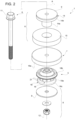
Figure 2 is an exploded perspective view of the suspension arrangement shown infigure 1 ; -
Figure 3 is transversal sectional view of the suspension arrangement shown infigure 1 ; -
Figure 4 is a functional schematic representing the mechanical operation of the suspension arrangement according to the present invention; and -
Figures 5 and 6 are diagrams showing the dynamic behavior of a suspension arrangement of the present invention. -
Figures 1 to 3 show asuspension arrangement 1 interposed between acab portion 2 and abody portion 3 of the vehicle. - The shape of
cab portion 2 andbody portion 3 is substantially irrelevant with respect to the operation of thesuspension arrangement 1 of the present invention and therefore their shape will be not described into detail. The only peculiar feature ofsuch portions respective end plates suspension arrangement 1 as described hereunder. - Furthermore, each of said
portions hole respective end plate Such holes suspension arrangement 1 as described in further detail below. -
Suspension arrangement 1 essentially comprises a primaryelastic block 5, a secondaryelastic block 6 and anintermediate mass 7 axially interposed between primary and secondaryelastic blocks - In greater detail, primary
elastic block 5,intermediate mass 7 and secondaryelastic block 6 are axially in series one with respect to the other along axis A and they are maintained together by an axial preload given bycompacting means 8. - In the described embodiment compacting means 8 comprises a
pair thrust plates 9 which are respectively positioned under primaryelastic block 5 and above secondaryelastic block 6 and pressed one against the other thanks to a threaded connection between ascrew 11 and anut 12 as better disclosed in the following. - Secondary
elastic block 6 cooperates at contact withcab portion 2 on one side and withintermediate mass 7 on the opposite side. In particular, secondaryelastic block 6 comprises a firstannular element 14 and a secondannular element 15 separated with respect to each other but cooperating at contact between themselves. - First
annular element 14 comprises acylindrical portion 14a configured to be housed in contact withinhole 2b ofend plate 2a and extending from both sides ofend plate 2a along axis A. Firstannular element 14 further comprises aflanged portion 14b extending from an upper terminal portion ofcylindrical portion 14a along an axis B perpendicular to axis A. Accordingly, flangedportion 14b cooperate at contact with a top surface ofend plate 2a ofcab portion 2. - Second
annular element 15 comprises preferably a single element having an annular cylindrical shape configured to surroundcylindrical portion 14a of firstannular element 14 and cooperate radially at contact with this latter. As said, secondannular element 15 is placed at opposite side ofend plate 2a with respect to flangedportion 14b, accordingly it cooperates axially at contact with a bottom surface, opposite to the one cooperating withflange portion 14b, ofend plate 2a. - Advantageously, first and
second elements first element 14 is made of natural rubber while thesecond element 15 is made of polyurethane, preferably having polyurethane with a mixture of closed and open cells foam. -
Intermediate mass 7 essentially comprises anannular disc element 16 coaxial to axis A.Annular disc element 16 comprises acylindrical portion 16a at contact with secondaryelastic block 6 and anannular portion 16b extending along at least part of an outer edge ofcylindrical portion 16a towards primaryelastic block 5 in a direction parallel to axis A. - Accordingly,
annular portion 16b delimits acontact surface 16c, opposite to the one in contact with secondaryelastic block 6 and configured to cooperate at contact with primaryelastic block 5 as defined in the following. Advantageously,annular disc element 16 is made in a high density material. Preferably, in metallic material, such as steel or cast iron. - Primary
elastic block 5 essentially comprises a singleannular element 18 provided with a main cylindricalannular portion 18a which is dimensioned to be housed in contact withinhole 3b ofend plate 3 of vehicle's body. -
Element 18 further comprises a pair ofannular lips outer lip 18b and a lower annularouter lip 18c extending from respectively an upper outer edge of cylindricalmain portion 18a and a lower outer edge of cylindricalmain portion 18a. - Annular
outer lips outer lip 18b has a substantial trapezoidal cross-section connected at a corner to upper outer edge ofmain portion 18a, while lower annularouter lip 18c has a substantial circular cross-section connected to lower outer edge ofmain portion 18a via a joint portion. - Accordingly,
main portion 18a defines a lateral surface axially comprised betweenannular lips hole 3b. Advantageously,element 18 comprises contact means 19 attached to lateral surface ofmain portion 18a and configured to improve the contact with inner surface ofhole 3b. - As can be better appreciated in
figures 1 and2 , such contact means 19 preferably comprises a plurality ofpads 21 realized integrally withmain portion 18a and extending from the lateral surface thereof parallel to axis B direction. In the described exemplarily embodiment,pads 21 have each an equal substantial rectangular shape and are equally spaced one with the other about axis A on lateral surface ofmain portion 18a. - Advantageously,
element 18 further comprises an upper annularinner lip 18d and a lower annularinner lip 18e extending from respectively a top surface of cylindricalmain portion 18a and bottom surface of cylindricalmain portion 18a. - Annular
inner lips inner lips main portion 18a. Always according to the described embodiment, lower annularinner lip 18e is closer to axis A with respect to upper annularinner lip 18d, i.e. its diameter is lower than the diameter of the latter. - Advantageously
element 18 further comprises an upperannular lip 18f and a lowerannular lip 18g extending over respectively annularinner lips annular element 18 and configured to cooperate at contact withscrew 11. - As shown clearly in
figure 3 andfigure 1 , primaryelastic block 5 further comprises areinforce element 22 configured to increase stiffness ofsingle element 18 and partially sunk within this latter. Advantageously reinforceelement 22 comprises anannular element 23 having preferably a "L"-shaped cross section, i.e. comprises anannular disc portion 23a and an annularcylindrical portion 23b extending from an edge of suchannular disc portion 23a. In particular,annular disc portion 23a is parallel toend plate 3a of vehicle'sbody portion 3 and positioned upper annularouter lip 18b while annularcylindrical portion 23b extends towardslower thrust plate 9. - According to the described embodiment,
annular element 23 is totally sunk withinmain portion 18a. - The aforementioned plurality of contact means 19, preferably
pads 21, realized integrally withmain portion 18 are positioned in front of bothannular disc portion 23a and annularcylindrical portion 23b. More preferably, the have a shape and distribution preferably similar to the already describedpads 21. -
Such pads 21 are configured to cooperate at contact respectively with top surface ofend plate 3a of vehicle'sbody portion 3 and lateral surface ofhole 3b in order to increase the friction contact betweenelastic bloc 5 withbody portion 3. - Advantageously,
single element 18 is made in polymeric material, preferably natural rubber. - According to the above configuration, is clear that
screw 11 pass through all the described elements, i.e. through holes defined byfirst element 14 of secondary elastic block, byannular disc element 16 ofintermediate mass 7 and bymain potion 18a ofsingle element 18 of primaryelastic block 5. - In particular, according to the exemplarily described embodiment, it has to be noted that
lower thrust plate 9 is in contact but separated by primaryelastic block 5 whileupper thrust plate 9 is preferably realized as one piece, i.e. sink, withfirst element 14. - Preferably, first and/or second
elastic blocks screw 11. In particular, such sliding means may comprise abushing 24 housed coaxially externally with respect to screw 11 and radially interposed with first and secondelastic blocks - In the described embodiment, a
first bushing 24 is interposed betweenscrew 11 andfirst element 14, i.e. external surface ofbushing 24 is in contact with an inner surface ofcylindrical portion 14a offirst element 14 and asecond bushing 24 is interposed betweenscrew 11 andsingle element 18, i.e. external surface ofbushing 24 is in contact with an inner surface ofmain portion 18a ofelement 18 and with inner surface of annularinner lips - The operation of a
suspension arrangement 1 as described above will be described making reference tofigure 4 schematic and to diagrams offigures 5 and 6 . - The assembly of
suspension arrangement 1 is clear: all elements are made coaxially toholes screw 11 which engages withnut 12 to provide a suitable preload to maintain compact all the elements along axis A. - When mounted, any force, impulse or noise coming from vehicle's body via
portion 3 is dampened by suspension arrangement to avoid a transmission to the cab. Such dynamic behaviors is schematized infigure 4 into which the proposedsuspension arrangement system 1 is enclosed in module III between cab of the vehicle, represented by module I, and body of the vehicle, represented by module II. - Accordingly, module I and module II each comprises a mass M2, M3 representing the mass of respectively cab and body of the vehicle connected by a stiffness K2, K3 to the
suspension arrangement 1 represented module III. Stiffness K2, K3 are respectively the stiffness ofportions suspension 1; since such elements are rigid metallic elements, stiffness K2, K3 have a very high value, i.e. ideally infinite. - Module III represents
suspension 1 which can be summarized as a first stiffness K5 representing the stiffness of primaryelastic block 5, a second stiffness K6 representing the stiffness of secondaryelastic block 6 in series with respect to first stiffness K5 and a mass M7 representing the mass ofintermediate element 7 interposed between first and second stiffness K5 and K6. - K5, K6 and M7 values can be tuned according to the given values of M2, M3, K2 and K3 in order to provide a good performance of module III in order to reduce both noise and roll motion of module I transmitted from module II at low and high frequencies.
- Indeed, K5 may have a value comprised between 150 N/mm and 400 N/mm configured to dampen low frequency, e.g. associated to shakings up to about 700 Hz, usually frequency of high energy noise. Sinergically, K6 may have a value comprised between 1000 N/mm and 2000 N/mm configured to dampen high frequency, i.e. from about 1,4 kHz and above, usually frequency of low energy noise.
- Mass M7 may have a weight comprised between 4 kg and 10 Kg.
- For sake of example, K3 may be greater than 40kN/mm and K2 may be greater than 30kN/mm while M2 is usually comprised between 150 kg and 300 kg and M3 may be more than 1000 kg.
-
Figures 5 and 6 show a double pick transfer functions obtained by asuspension arrangement 1 according to the invention. In particular, X-axis of diagrams show frequency (in Hz) of an excitation given by vehicle's body, i.e. by mass M3, and Y-axis show the acceleration (in mm/s2) of cab suspended mass M5. - It is clear that the proposed system guarantees a greater damping at low frequency a low damping for high frequency, thereby allowing to dampen all sources of noise/vibrations.
- In particular it may be noticed, as shown in
figures 5 and 6 that values of stiffness K6 and mass M7 may be regulated in order to allow greater damping respectively at higher frequencies, e.g. as shown by increasing stiffness K6, or at lower frequencies, e.g. as shown by increasing weight M7. The above proposed range values represents an optimum compromise to guarantee a good dampening for all vibration frequency range. - In view of the foregoing, the advantages of a work vehicle and a
suspension arrangement 1 according to the invention are apparent. - The provided suspension arrangement allows to maintain the transmitted acceleration within a value lower with respect to 0.5g, i.e. as known within a good value of comfort.
- Indeed, the presence of two different
elastic blocks intermediate mass 7 allows to provide a good dampening both at low and at high frequencies, i.e. to dampen both noise and roll motions. - The proposed geometry of primary
silent block 5 deforms under loads in order to provide a good noise attenuation at low frequency/high energy. - The proposed material of secondary
silent block 6 allows to damping a wide range of medium-high frequency. Moreover, the use of polyurethane has a reduced Payne effect, i.e. it has low dynamic stiffness also at high frequencies. - The
intermediate mass 7 acts as a damper, thereby further decreasing noise transmission, especially at high frequencies. - In general, the proposed shapes, material and disposition of elements allow to reduce inertance at connection points of elastic blocks. Inertance, as known, is defined as the ration between accelerations (output) and forces (input) in a dynamic mechanical system. Accordingly, low inertance equals to low transmission of accelerations.
- The proposed
suspension arrangement 1 is easy and quick to be mounted, thereby reducing timing for the manufacturing of the cab and thereby increasing cost-savings. Moreover, the proposed system is really compact and has a great durability. - It is clear that modifications can be made to the described work vehicle and
suspension arrangement 1 which do not extend beyond the scope of protection defined by the claims. - Furthermore, it is clear that shapes of the proposed elements may be varied within the scope limited by the attached claims.
- Again, indicated values of mass and stiffness are merely exemplarily and may vary according to the mass, typology and use of the work vehicle into which the
suspension arrangement 1 is incorporated.
Claims (19)
- Work vehicle comprising a body and a cab, said body comprising a portion (3) and said cab comprising a portion (2) faced to a portion of said body, said vehicle comprising a suspension arrangement (1) for connecting said portions (2, 3), said suspension arrangement (1) comprising a primary elastic block (5), a second elastic block (6) and an intermediate mass (7) acting as a damper, thereby further decreasing noise transmission, especially at high frequencies and interposed in series along an axis (A) between said first and second elastic blocks (5, 6), characterized in that said primary elastic block (5) cooperates at contact with a portion (3) of said body from one side and with said intermediate mass (7) from the opposite side, said second elastic block (6) cooperates at contact with a portion (2) of said cab from one side and with said intermediate mass (7) from the opposite side, said first and second elastic blocks (5, 6) and said intermediate mass (7) being maintained in contact with the aforesaid elements in a preset preload along said axis (A) thanks to compacting means (8).
- Work vehicle according to claim 1 , wherein said intermediate mass (7) has a mass (M7) comprised between 4 and 10 kg.
- Work vehicle according to claim 1 or 2, wherein said primary elastic block (5) has a stiffness comprised between 150 N/mm and 400 N/mm.
- Work vehicle according to any of claims 1 to 3, wherein said second elastic block (6) has a stiffness comprised between 1000 N/mm and 2000 N/mm.
- Work vehicle according to any of claims 1 to 4, wherein said first and second elastic blocks (5, 6) and said intermediate mass (7) have an axisymmetric shape.
- Work vehicle according to any of claims 1 to 5, wherein said first and second elastic blocks (5, 6) and said intermediate mass (7) each define a respective hole, said portions (2, 3) each comprises an end plate (2a, 3a) defining a respective hole (2b, 3b), these latter and the holes defined by said first and second elastic blocks (5, 6) and said intermediate mass (7) being coaxial, said compacting means (8) comprising a screw (11) configured to pass through all the aforesaid holes, a nut (12) configured to engage said screw from an opposite side of said suspension arrangement (1) with respect to the insertion side of said screw (11), said nut (12) engaging said screw (11) providing said preset preload.
- Work vehicle according to claim 6, wherein said intermediate mass (7) comprises an annular disc element (16) comprising a cylindrical portion (16a) being in contact with said second elastic block (6) from one side and an annular portion (14b) extending perpendicularly from said cylindrical portion (16a) from the side opposite to the one in contact with said second elastic block (6) and delimiting a contact surface (16c) at contact with said primary elastic block (5).
- Work vehicle according to claim 6 or 7, wherein second elastic block (6) comprises a first annular element (14) and a second annular element (15) separated with respect to each other but cooperating at contact between themselves.
- Work vehicle according to claim 8, wherein first annular element (14) comprises a cylindrical portion (14a) configured to be housed in contact within hole (2b) of end plate (2a) and extending from both sides of this latter, and a flanged portion (14b) extending perpendicularly from an upper terminal portion of cylindrical portion (14a) A, said flanged portion (14b) cooperating at contact with a top surface of said end plate (2a), said second annular element (15) comprising a single element having an annular cylindrical shape configured to surround said cylindrical portion (14a) and radially cooperating at contact with this latter, said second annular element (15) axially cooperating at contact from one side with said end plate (2a) and with said intermediate mass (7) from the opposite.
- Work vehicle according to any of claims 6 to 9, wherein primary elastic block (5) comprises a single element (18) provided with a main cylindrical annular portion (18a) which is dimensioned to be housed in contact within said hole (3b) of said end plate (3) and a plurality of lips (18b, 18c, 18d, 18e, 18f, 18g) extending from said main cylindrical annular portion (18a) and cooperating with at least one between said end plate (3a) and said intermediate mass (7).
- Work vehicle according to claim 10, wherein said primary elastic block (5) comprises contact means (19) configured to improve contact of said single element (18) with said end plate (3a).
- Work vehicle according to claim 11, wherein said contact means (19) comprises a plurality of pads (21) extending realized integrally with said single element (18) and protruding with respect to at least an external surface thereof.
- Work vehicle according to any of the preceding claims, wherein said intermediate mass (7) is realized in metallic material.
- Work vehicle according to any of the preceding claims, wherein said first and second elastic blocks (5, 6) are realized in polymeric material.
- Work vehicle according to any of the preceding claims, wherein said primary elastic block (5) is made of natural rubber.
- Work vehicle according to any of claims 8 to 15, wherein said first annular element (14) and said second annular element (15) are realized in different polymeric materials.
- Work vehicle according to claim 16, wherein said first annular element (14) is made according to claim 16, wherein said first annular element (14) is made of rubber while said second annular element (15) is made of polyurethane.
- Work vehicle according to claim 16 or claim 17, wherein said polyurethane material comprises a mixed closed and open cell polyurethane.
- Work vehicle according to any of claims 6 to 18, further comprising sliding means (24) interposed between each between said first and second elastic blocks (5, 6) and said screw (11).
Applications Claiming Priority (1)
| Application Number | Priority Date | Filing Date | Title |
|---|---|---|---|
| IT201900016616 | 2019-09-18 |
Publications (2)
| Publication Number | Publication Date |
|---|---|
| EP3798029A1 EP3798029A1 (en) | 2021-03-31 |
| EP3798029B1 true EP3798029B1 (en) | 2023-08-09 |
Family
ID=69158276
Family Applications (1)
| Application Number | Title | Priority Date | Filing Date |
|---|---|---|---|
| EP20196602.5A Active EP3798029B1 (en) | 2019-09-18 | 2020-09-17 | Suspension arrangement for a work vehicle |
Country Status (1)
| Country | Link |
|---|---|
| EP (1) | EP3798029B1 (en) |
Families Citing this family (1)
| Publication number | Priority date | Publication date | Assignee | Title |
|---|---|---|---|---|
| SE2351145A1 (en) | 2023-10-05 | 2024-11-12 | Limako Teknik Ab | Suspension Element and Construction Vehicle |
Citations (1)
| Publication number | Priority date | Publication date | Assignee | Title |
|---|---|---|---|---|
| DE1290830B (en) * | 1956-02-18 | 1969-03-13 | Maschf Augsburg Nuernberg Ag | Fastening the cab of trucks to the vehicle frame |
Family Cites Families (6)
| Publication number | Priority date | Publication date | Assignee | Title |
|---|---|---|---|---|
| GB1406091A (en) * | 1972-07-13 | 1975-09-17 | Brown Tractors Ltd | Tractor roll-bars and the like |
| JPS6015807B2 (en) * | 1980-04-17 | 1985-04-22 | 日産自動車株式会社 | engine mounting device |
| SE517882C2 (en) * | 1997-11-04 | 2002-07-30 | Volvo Wheel Loaders Ab | A mounting arrangement |
| GB0021140D0 (en) * | 1999-11-30 | 2000-10-11 | Kubota Kk | Dynamic dampers, and a damping support apparatus for a vehicle body using the dynamic dampers |
| JP4777867B2 (en) * | 2006-12-04 | 2011-09-21 | 株式会社ブリヂストン | Anti-vibration support device |
| KR20080092838A (en) * | 2007-04-12 | 2008-10-16 | 가부시끼 가이샤 구보다 | Driving vehicle with cabin |
-
2020
- 2020-09-17 EP EP20196602.5A patent/EP3798029B1/en active Active
Patent Citations (1)
| Publication number | Priority date | Publication date | Assignee | Title |
|---|---|---|---|---|
| DE1290830B (en) * | 1956-02-18 | 1969-03-13 | Maschf Augsburg Nuernberg Ag | Fastening the cab of trucks to the vehicle frame |
Also Published As
| Publication number | Publication date |
|---|---|
| EP3798029A1 (en) | 2021-03-31 |
Similar Documents
| Publication | Publication Date | Title |
|---|---|---|
| CA1124767A (en) | Powertrain and independent suspension mounting arrangement for front-wheel-drive vehicle | |
| US8083243B2 (en) | Drive unit vibration damping support for electric motor-driven vehicle | |
| US5242146A (en) | Engine mount having improved vibration isolation | |
| KR101237929B1 (en) | Structure of roll rod for vehicle | |
| US5330166A (en) | Upper mounting structure for a wheel suspension | |
| US5454443A (en) | Motor vehicle | |
| US5251928A (en) | Upper mounting structure for a strut-type wheel suspension | |
| US6540042B2 (en) | Bearing system for an engine-transmission unit | |
| JPH04224333A (en) | Bush type damping device and bush type liquid filling damping device | |
| US4440375A (en) | Engine mounting structure for automotive vehicle | |
| US4445662A (en) | Engine mounting structure | |
| JP5202852B2 (en) | Anti-vibration floating floor structure | |
| US5782462A (en) | Hydraulically damped powertrain mount | |
| EP3798029B1 (en) | Suspension arrangement for a work vehicle | |
| KR102218384B1 (en) | Vibration Damping Device For a Vehicle with Multiple Bridge Type Rubber Isolator | |
| KR20040026677A (en) | Cab suspension device | |
| US5947226A (en) | Motor vehicle including a power unit provided with a suspension of limited displacement | |
| JPH109261A (en) | Hydraulic buffer rubber bearing | |
| CA1240346A (en) | Tunable viscous spring mount | |
| US20190047395A1 (en) | Mounting bracket for a vehicle component and method of forming | |
| KR20230053975A (en) | Mounting bush | |
| KR100527784B1 (en) | engine mounting system for automotive vehicles | |
| CN118922649A (en) | Damper device and damper device | |
| US4858900A (en) | Mounting support arrangement for an engine and driving assembly of a motor vehicle which operates at a limited frequency range | |
| KR100475889B1 (en) | Reinforcing structure of engine mounying bracket for automobile |
Legal Events
| Date | Code | Title | Description |
|---|---|---|---|
| PUAI | Public reference made under article 153(3) epc to a published international application that has entered the european phase |
Free format text: ORIGINAL CODE: 0009012 |
|
| STAA | Information on the status of an ep patent application or granted ep patent |
Free format text: STATUS: THE APPLICATION HAS BEEN PUBLISHED |
|
| AK | Designated contracting states |
Kind code of ref document: A1 Designated state(s): AL AT BE BG CH CY CZ DE DK EE ES FI FR GB GR HR HU IE IS IT LI LT LU LV MC MK MT NL NO PL PT RO RS SE SI SK SM TR |
|
| AX | Request for extension of the european patent |
Extension state: BA ME |
|
| STAA | Information on the status of an ep patent application or granted ep patent |
Free format text: STATUS: REQUEST FOR EXAMINATION WAS MADE |
|
| 17P | Request for examination filed |
Effective date: 20210930 |
|
| RBV | Designated contracting states (corrected) |
Designated state(s): AL AT BE BG CH CY CZ DE DK EE ES FI FR GB GR HR HU IE IS IT LI LT LU LV MC MK MT NL NO PL PT RO RS SE SI SK SM TR |
|
| STAA | Information on the status of an ep patent application or granted ep patent |
Free format text: STATUS: EXAMINATION IS IN PROGRESS |
|
| 17Q | First examination report despatched |
Effective date: 20220617 |
|
| GRAP | Despatch of communication of intention to grant a patent |
Free format text: ORIGINAL CODE: EPIDOSNIGR1 |
|
| STAA | Information on the status of an ep patent application or granted ep patent |
Free format text: STATUS: GRANT OF PATENT IS INTENDED |
|
| INTG | Intention to grant announced |
Effective date: 20230303 |
|
| RAP3 | Party data changed (applicant data changed or rights of an application transferred) |
Owner name: CNH INDUSTRIAL ITALIA S.P.A. |
|
| GRAS | Grant fee paid |
Free format text: ORIGINAL CODE: EPIDOSNIGR3 |
|
| GRAA | (expected) grant |
Free format text: ORIGINAL CODE: 0009210 |
|
| STAA | Information on the status of an ep patent application or granted ep patent |
Free format text: STATUS: THE PATENT HAS BEEN GRANTED |
|
| AK | Designated contracting states |
Kind code of ref document: B1 Designated state(s): AL AT BE BG CH CY CZ DE DK EE ES FI FR GB GR HR HU IE IS IT LI LT LU LV MC MK MT NL NO PL PT RO RS SE SI SK SM TR |
|
| REG | Reference to a national code |
Ref country code: GB Ref legal event code: FG4D |
|
| REG | Reference to a national code |
Ref country code: CH Ref legal event code: EP |
|
| REG | Reference to a national code |
Ref country code: IE Ref legal event code: FG4D |
|
| REG | Reference to a national code |
Ref country code: DE Ref legal event code: R096 Ref document number: 602020015295 Country of ref document: DE |
|
| REG | Reference to a national code |
Ref country code: LT Ref legal event code: MG9D |
|
| REG | Reference to a national code |
Ref country code: NL Ref legal event code: MP Effective date: 20230809 |
|
| REG | Reference to a national code |
Ref country code: AT Ref legal event code: MK05 Ref document number: 1597108 Country of ref document: AT Kind code of ref document: T Effective date: 20230809 |
|
| PG25 | Lapsed in a contracting state [announced via postgrant information from national office to epo] |
Ref country code: GR Free format text: LAPSE BECAUSE OF FAILURE TO SUBMIT A TRANSLATION OF THE DESCRIPTION OR TO PAY THE FEE WITHIN THE PRESCRIBED TIME-LIMIT Effective date: 20231110 |
|
| PG25 | Lapsed in a contracting state [announced via postgrant information from national office to epo] |
Ref country code: IS Free format text: LAPSE BECAUSE OF FAILURE TO SUBMIT A TRANSLATION OF THE DESCRIPTION OR TO PAY THE FEE WITHIN THE PRESCRIBED TIME-LIMIT Effective date: 20231209 |
|
| PG25 | Lapsed in a contracting state [announced via postgrant information from national office to epo] |
Ref country code: SE Free format text: LAPSE BECAUSE OF FAILURE TO SUBMIT A TRANSLATION OF THE DESCRIPTION OR TO PAY THE FEE WITHIN THE PRESCRIBED TIME-LIMIT Effective date: 20230809 Ref country code: RS Free format text: LAPSE BECAUSE OF FAILURE TO SUBMIT A TRANSLATION OF THE DESCRIPTION OR TO PAY THE FEE WITHIN THE PRESCRIBED TIME-LIMIT Effective date: 20230809 Ref country code: PT Free format text: LAPSE BECAUSE OF FAILURE TO SUBMIT A TRANSLATION OF THE DESCRIPTION OR TO PAY THE FEE WITHIN THE PRESCRIBED TIME-LIMIT Effective date: 20231211 Ref country code: NO Free format text: LAPSE BECAUSE OF FAILURE TO SUBMIT A TRANSLATION OF THE DESCRIPTION OR TO PAY THE FEE WITHIN THE PRESCRIBED TIME-LIMIT Effective date: 20231109 Ref country code: NL Free format text: LAPSE BECAUSE OF FAILURE TO SUBMIT A TRANSLATION OF THE DESCRIPTION OR TO PAY THE FEE WITHIN THE PRESCRIBED TIME-LIMIT Effective date: 20230809 Ref country code: LV Free format text: LAPSE BECAUSE OF FAILURE TO SUBMIT A TRANSLATION OF THE DESCRIPTION OR TO PAY THE FEE WITHIN THE PRESCRIBED TIME-LIMIT Effective date: 20230809 Ref country code: LT Free format text: LAPSE BECAUSE OF FAILURE TO SUBMIT A TRANSLATION OF THE DESCRIPTION OR TO PAY THE FEE WITHIN THE PRESCRIBED TIME-LIMIT Effective date: 20230809 Ref country code: IS Free format text: LAPSE BECAUSE OF FAILURE TO SUBMIT A TRANSLATION OF THE DESCRIPTION OR TO PAY THE FEE WITHIN THE PRESCRIBED TIME-LIMIT Effective date: 20231209 Ref country code: HR Free format text: LAPSE BECAUSE OF FAILURE TO SUBMIT A TRANSLATION OF THE DESCRIPTION OR TO PAY THE FEE WITHIN THE PRESCRIBED TIME-LIMIT Effective date: 20230809 Ref country code: GR Free format text: LAPSE BECAUSE OF FAILURE TO SUBMIT A TRANSLATION OF THE DESCRIPTION OR TO PAY THE FEE WITHIN THE PRESCRIBED TIME-LIMIT Effective date: 20231110 Ref country code: FI Free format text: LAPSE BECAUSE OF FAILURE TO SUBMIT A TRANSLATION OF THE DESCRIPTION OR TO PAY THE FEE WITHIN THE PRESCRIBED TIME-LIMIT Effective date: 20230809 Ref country code: AT Free format text: LAPSE BECAUSE OF FAILURE TO SUBMIT A TRANSLATION OF THE DESCRIPTION OR TO PAY THE FEE WITHIN THE PRESCRIBED TIME-LIMIT Effective date: 20230809 |
|
| PG25 | Lapsed in a contracting state [announced via postgrant information from national office to epo] |
Ref country code: PL Free format text: LAPSE BECAUSE OF FAILURE TO SUBMIT A TRANSLATION OF THE DESCRIPTION OR TO PAY THE FEE WITHIN THE PRESCRIBED TIME-LIMIT Effective date: 20230809 |
|
| PG25 | Lapsed in a contracting state [announced via postgrant information from national office to epo] |
Ref country code: ES Free format text: LAPSE BECAUSE OF FAILURE TO SUBMIT A TRANSLATION OF THE DESCRIPTION OR TO PAY THE FEE WITHIN THE PRESCRIBED TIME-LIMIT Effective date: 20230809 |
|
| PG25 | Lapsed in a contracting state [announced via postgrant information from national office to epo] |
Ref country code: SM Free format text: LAPSE BECAUSE OF FAILURE TO SUBMIT A TRANSLATION OF THE DESCRIPTION OR TO PAY THE FEE WITHIN THE PRESCRIBED TIME-LIMIT Effective date: 20230809 Ref country code: RO Free format text: LAPSE BECAUSE OF FAILURE TO SUBMIT A TRANSLATION OF THE DESCRIPTION OR TO PAY THE FEE WITHIN THE PRESCRIBED TIME-LIMIT Effective date: 20230809 Ref country code: ES Free format text: LAPSE BECAUSE OF FAILURE TO SUBMIT A TRANSLATION OF THE DESCRIPTION OR TO PAY THE FEE WITHIN THE PRESCRIBED TIME-LIMIT Effective date: 20230809 Ref country code: EE Free format text: LAPSE BECAUSE OF FAILURE TO SUBMIT A TRANSLATION OF THE DESCRIPTION OR TO PAY THE FEE WITHIN THE PRESCRIBED TIME-LIMIT Effective date: 20230809 Ref country code: DK Free format text: LAPSE BECAUSE OF FAILURE TO SUBMIT A TRANSLATION OF THE DESCRIPTION OR TO PAY THE FEE WITHIN THE PRESCRIBED TIME-LIMIT Effective date: 20230809 Ref country code: CZ Free format text: LAPSE BECAUSE OF FAILURE TO SUBMIT A TRANSLATION OF THE DESCRIPTION OR TO PAY THE FEE WITHIN THE PRESCRIBED TIME-LIMIT Effective date: 20230809 Ref country code: SK Free format text: LAPSE BECAUSE OF FAILURE TO SUBMIT A TRANSLATION OF THE DESCRIPTION OR TO PAY THE FEE WITHIN THE PRESCRIBED TIME-LIMIT Effective date: 20230809 |
|
| REG | Reference to a national code |
Ref country code: CH Ref legal event code: PL |
|
| REG | Reference to a national code |
Ref country code: DE Ref legal event code: R097 Ref document number: 602020015295 Country of ref document: DE |
|
| PG25 | Lapsed in a contracting state [announced via postgrant information from national office to epo] |
Ref country code: LU Free format text: LAPSE BECAUSE OF NON-PAYMENT OF DUE FEES Effective date: 20230917 |
|
| REG | Reference to a national code |
Ref country code: BE Ref legal event code: MM Effective date: 20230930 |
|
| PG25 | Lapsed in a contracting state [announced via postgrant information from national office to epo] |
Ref country code: LU Free format text: LAPSE BECAUSE OF NON-PAYMENT OF DUE FEES Effective date: 20230917 Ref country code: MC Free format text: LAPSE BECAUSE OF FAILURE TO SUBMIT A TRANSLATION OF THE DESCRIPTION OR TO PAY THE FEE WITHIN THE PRESCRIBED TIME-LIMIT Effective date: 20230809 |
|
| PLBE | No opposition filed within time limit |
Free format text: ORIGINAL CODE: 0009261 |
|
| STAA | Information on the status of an ep patent application or granted ep patent |
Free format text: STATUS: NO OPPOSITION FILED WITHIN TIME LIMIT |
|
| REG | Reference to a national code |
Ref country code: IE Ref legal event code: MM4A |
|
| PG25 | Lapsed in a contracting state [announced via postgrant information from national office to epo] |
Ref country code: IE Free format text: LAPSE BECAUSE OF NON-PAYMENT OF DUE FEES Effective date: 20230917 |
|
| 26N | No opposition filed |
Effective date: 20240513 |
|
| PG25 | Lapsed in a contracting state [announced via postgrant information from national office to epo] |
Ref country code: CH Free format text: LAPSE BECAUSE OF NON-PAYMENT OF DUE FEES Effective date: 20230930 |
|
| PG25 | Lapsed in a contracting state [announced via postgrant information from national office to epo] |
Ref country code: IE Free format text: LAPSE BECAUSE OF NON-PAYMENT OF DUE FEES Effective date: 20230917 Ref country code: CH Free format text: LAPSE BECAUSE OF NON-PAYMENT OF DUE FEES Effective date: 20230930 Ref country code: SI Free format text: LAPSE BECAUSE OF FAILURE TO SUBMIT A TRANSLATION OF THE DESCRIPTION OR TO PAY THE FEE WITHIN THE PRESCRIBED TIME-LIMIT Effective date: 20230809 |
|
| PG25 | Lapsed in a contracting state [announced via postgrant information from national office to epo] |
Ref country code: BE Free format text: LAPSE BECAUSE OF NON-PAYMENT OF DUE FEES Effective date: 20230930 |
|
| PG25 | Lapsed in a contracting state [announced via postgrant information from national office to epo] |
Ref country code: BG Free format text: LAPSE BECAUSE OF FAILURE TO SUBMIT A TRANSLATION OF THE DESCRIPTION OR TO PAY THE FEE WITHIN THE PRESCRIBED TIME-LIMIT Effective date: 20230809 |
|
| PG25 | Lapsed in a contracting state [announced via postgrant information from national office to epo] |
Ref country code: BG Free format text: LAPSE BECAUSE OF FAILURE TO SUBMIT A TRANSLATION OF THE DESCRIPTION OR TO PAY THE FEE WITHIN THE PRESCRIBED TIME-LIMIT Effective date: 20230809 |
|
| PG25 | Lapsed in a contracting state [announced via postgrant information from national office to epo] |
Ref country code: CY Free format text: LAPSE BECAUSE OF FAILURE TO SUBMIT A TRANSLATION OF THE DESCRIPTION OR TO PAY THE FEE WITHIN THE PRESCRIBED TIME-LIMIT; INVALID AB INITIO Effective date: 20200917 |
|
| PG25 | Lapsed in a contracting state [announced via postgrant information from national office to epo] |
Ref country code: HU Free format text: LAPSE BECAUSE OF FAILURE TO SUBMIT A TRANSLATION OF THE DESCRIPTION OR TO PAY THE FEE WITHIN THE PRESCRIBED TIME-LIMIT; INVALID AB INITIO Effective date: 20200917 |
|
| PGFP | Annual fee paid to national office [announced via postgrant information from national office to epo] |
Ref country code: DE Payment date: 20250926 Year of fee payment: 6 |
|
| PGFP | Annual fee paid to national office [announced via postgrant information from national office to epo] |
Ref country code: IT Payment date: 20250922 Year of fee payment: 6 |
|
| PGFP | Annual fee paid to national office [announced via postgrant information from national office to epo] |
Ref country code: GB Payment date: 20250923 Year of fee payment: 6 |
|
| PGFP | Annual fee paid to national office [announced via postgrant information from national office to epo] |
Ref country code: FR Payment date: 20250925 Year of fee payment: 6 |
|
| PG25 | Lapsed in a contracting state [announced via postgrant information from national office to epo] |
Ref country code: TR Free format text: LAPSE BECAUSE OF FAILURE TO SUBMIT A TRANSLATION OF THE DESCRIPTION OR TO PAY THE FEE WITHIN THE PRESCRIBED TIME-LIMIT Effective date: 20230809 |