EP3797939B1 - Steuerbefehlbasiertes adaptives system und verfahren zur schätzung von bewegungsparametern von fahrzeugen mit differentialantrieb - Google Patents
Steuerbefehlbasiertes adaptives system und verfahren zur schätzung von bewegungsparametern von fahrzeugen mit differentialantrieb Download PDFInfo
- Publication number
- EP3797939B1 EP3797939B1 EP20191743.2A EP20191743A EP3797939B1 EP 3797939 B1 EP3797939 B1 EP 3797939B1 EP 20191743 A EP20191743 A EP 20191743A EP 3797939 B1 EP3797939 B1 EP 3797939B1
- Authority
- EP
- European Patent Office
- Prior art keywords
- model
- motion parameters
- differential drive
- input signals
- command input
- Prior art date
- Legal status (The legal status is an assumption and is not a legal conclusion. Google has not performed a legal analysis and makes no representation as to the accuracy of the status listed.)
- Active
Links
Images


Classifications
-
- B—PERFORMING OPERATIONS; TRANSPORTING
- B25—HAND TOOLS; PORTABLE POWER-DRIVEN TOOLS; MANIPULATORS
- B25J—MANIPULATORS; CHAMBERS PROVIDED WITH MANIPULATION DEVICES
- B25J9/00—Programme-controlled manipulators
- B25J9/16—Programme controls
- B25J9/1628—Programme controls characterised by the control loop
- B25J9/163—Programme controls characterised by the control loop learning, adaptive, model based, rule based expert control
-
- G—PHYSICS
- G01—MEASURING; TESTING
- G01D—MEASURING NOT SPECIALLY ADAPTED FOR A SPECIFIC VARIABLE; ARRANGEMENTS FOR MEASURING TWO OR MORE VARIABLES NOT COVERED IN A SINGLE OTHER SUBCLASS; TARIFF METERING APPARATUS; MEASURING OR TESTING NOT OTHERWISE PROVIDED FOR
- G01D21/00—Measuring or testing not otherwise provided for
- G01D21/02—Measuring two or more variables by means not covered by a single other subclass
-
- G—PHYSICS
- G05—CONTROLLING; REGULATING
- G05D—SYSTEMS FOR CONTROLLING OR REGULATING NON-ELECTRIC VARIABLES
- G05D1/00—Control of position, course, altitude or attitude of land, water, air or space vehicles, e.g. using automatic pilots
- G05D1/02—Control of position or course in two dimensions
- G05D1/021—Control of position or course in two dimensions specially adapted to land vehicles
- G05D1/0212—Control of position or course in two dimensions specially adapted to land vehicles with means for defining a desired trajectory
- G05D1/0221—Control of position or course in two dimensions specially adapted to land vehicles with means for defining a desired trajectory involving a learning process
-
- G—PHYSICS
- G06—COMPUTING OR CALCULATING; COUNTING
- G06F—ELECTRIC DIGITAL DATA PROCESSING
- G06F18/00—Pattern recognition
- G06F18/20—Analysing
- G06F18/21—Design or setup of recognition systems or techniques; Extraction of features in feature space; Blind source separation
- G06F18/214—Generating training patterns; Bootstrap methods, e.g. bagging or boosting
-
- G—PHYSICS
- G06—COMPUTING OR CALCULATING; COUNTING
- G06F—ELECTRIC DIGITAL DATA PROCESSING
- G06F18/00—Pattern recognition
- G06F18/20—Analysing
- G06F18/21—Design or setup of recognition systems or techniques; Extraction of features in feature space; Blind source separation
- G06F18/217—Validation; Performance evaluation; Active pattern learning techniques
-
- G—PHYSICS
- G06—COMPUTING OR CALCULATING; COUNTING
- G06F—ELECTRIC DIGITAL DATA PROCESSING
- G06F18/00—Pattern recognition
- G06F18/20—Analysing
- G06F18/25—Fusion techniques
- G06F18/251—Fusion techniques of input or preprocessed data
-
- G—PHYSICS
- G06—COMPUTING OR CALCULATING; COUNTING
- G06N—COMPUTING ARRANGEMENTS BASED ON SPECIFIC COMPUTATIONAL MODELS
- G06N20/00—Machine learning
-
- B—PERFORMING OPERATIONS; TRANSPORTING
- B25—HAND TOOLS; PORTABLE POWER-DRIVEN TOOLS; MANIPULATORS
- B25J—MANIPULATORS; CHAMBERS PROVIDED WITH MANIPULATION DEVICES
- B25J9/00—Programme-controlled manipulators
- B25J9/16—Programme controls
- B25J9/1656—Programme controls characterised by programming, planning systems for manipulators
- B25J9/1664—Programme controls characterised by programming, planning systems for manipulators characterised by motion, path, trajectory planning
Definitions
- the invention generally relates to the field of estimating motion parameters, more particularly, to control command based adaptive system and method for estimating motion parameters of differential drive vehicles.
- the embodiments herein provide control command based adaptive system and method for estimating motion parameters of differential drive vehicles.
- the typical interpretation of results obtained from conventional motion parameter estimation methods has been modified to solve a problem of accurate localization of vehicles and/or robots using only interceptive sensors and adapting to challenging scenarios such as presence of different terrains, change in payload of the differential vehicle, friction, and the like.
- the method of present disclosure utilizes a plurality of time synchronized command input signals provided to mobile robot of the differential drive vehicle for estimation of velocity thereof. Further, an experimental model has been generated, which provides relationship between the plurality of time synchronized command input signals and the velocity of the differential drive vehicle.
- the generated experimental model was adaptively updated to compute one or more motion parameters of the differential drive vehicle in real time, by fusing information from a plurality of sensors, the plurality of time synchronized command input signals and orientation information received from an onboard Inertial Measurement Unit (IMU).
- IMU Inertial Measurement Unit
- FIG. 1 through FIG. 8R where similar reference characters denote corresponding features consistently throughout the figures, there are shown preferred embodiments and these embodiments are described in the context of the following exemplary system and/or method.
- FIG. 1 illustrates an exemplary robot network environment 100 with a system 104 for implementing control command based adaptive system and method for estimating motion parameters of differential drive vehicles, in accordance with an embodiment of present disclosure.
- the robot network environment 100 utilizes a plurality of sensors 106 and the system 104 for estimating motion parameters of differential drive vehicle 102.
- the differential drive vehicle 102 is an autonomous four wheeled mobile robot which moves in the robot network environment.
- the robot network environment includes an indoor network area as well as outdoor network area where the differential drive vehicle moves on different surface terrains.
- the system 104 can be implemented as a unit within the differential drive vehicle 102. In an embodiment, the system 104 can be implemented as a stand-alone unit separated from the differential drive vehicle 102. In an embodiment, the plurality of sensors 106 may reside in the system 104 and/or may act as standalone unit. The system 104 is configured to process and analyze the data received from the plurality of sensors 106, and differential drive vehicle 102 for estimating motion parameters using control command input based adaptive methods. The system 104 is configured to process and analyze the received data in accordance with a plurality of models, further explained in conjunction with FIG. 2 through FIG. 5 , and FIG. 7 .
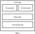
- FIG. 2 illustrates a block diagram of the system 104 of FIG. 1 for control command based adaptive system and method for estimating motion parameters of differential drive vehicles in the robot network environment 100 of FIG. 1 , according to some embodiments of the present disclosure.
- the system 104 includes or is otherwise in communication with one or more hardware processors such as a processor 206, an Input/Output interface 204, and at least one memory such as a memory 202.
- the processor 206, the I/O interface 204, and the memory 202 may be coupled by a system bus (not shown in FIG. 2 ).
- the I/O interface 204 may include a variety of software and hardware interfaces, for example, a web interface, a graphical user interface, and the like.
- the interfaces 204 may include a variety of software and hardware interfaces, for example, interfaces for peripheral device(s), such as a keyboard, a mouse, an external memory, a camera device, and a printer.
- the interfaces 204 can facilitate multiple communications within a wide variety of networks and protocol types, including wired networks, for example, local area network (LAN), cable, etc., and wireless networks, such as Wireless LAN (WLAN), cellular, or satellite.
- the interfaces 204 may include one or more ports for connecting a number of computing systems with one another or to another server computer.
- the I/O interface 204 may include one or more ports for connecting a number of devices to one another or to another server.
- the hardware processor 206 may be implemented as one or more microprocessors, microcomputers, microcontrollers, digital signal processors, central processing units, state machines, combinational circuits, application specific integrated circuits, semiconductor devices, logic circuitries including switches, and/or any devices that manipulate signals based on operational instructions.
- the hardware processor 206 is configured to fetch and execute computer-readable instructions stored in the memory 202.
- the memory 202 may include any computer-readable medium known in the art including, for example, volatile memory, such as static random access memory (SRAM) and dynamic random access memory (DRAM), and/or non-volatile memory, such as read only memory (ROM), erasable programmable ROM, flash memories, hard disks, optical disks, and magnetic tapes.
- the memory 202 includes a data repository 210 for storing data processed, received, and generated as output(s) by the system 104.
- the memory 202 stores a plurality of models such as known non-linear model, generated experimental model (alternatively referred as offline models) and adaptively updated models (alternatively referred as online models) which are further used for estimating motion parameters of differential drive vehicles in the robot network environment 100.
- the plurality of models stored in the memory 202 may include routines, programs, objects, components, data structures, and so on, which perform particular tasks or implement particular (abstract) data types.
- the data repository 210 includes a system database and other data.
- the system database may store information but are not limited to, a plurality of parameters obtained from the plurality of sensors, wherein the parameters are specific to an entity (e.g., machine such as robot, vehicle, and the like).
- the plurality of parameters may comprise sensor data captured through the plurality of sensors connected to the machine.
- the database 208 stores information pertaining to inputs fed to the system 104 and/or outputs generated by the system (e.g., at each stage), specific to the methodology described herein. More specifically, the system database stores information being processed at each step of the proposed methodology.
- the other data may include, data generated as a result of the execution of the plurality of models stored in the memory 202. The generated data may be further learnt to provide improved learning of the plurality of models in the next iterations to output desired results with improved accuracy.
- the one or more hardware processors 206 can be configured to perform control command based adaptive method for estimating motion parameters of differential drive vehicles which can be carried out by using methodology, described in conjunction with FIG. 3 , FIG. 4 , and use case examples.
- FIG. 3 illustrate an exemplary flow diagram of a processor implemented method 300, implemented by the system 104 of FIG. 1 and FIG. 2 for implementing control command based adaptive method for estimating motion parameters of differential drive vehicles, in accordance with some embodiments of the present disclosure.
- the one or more hardware processors 206 input one or more time synchronized command input signals to a moving differential drive vehicle.
- the one or more time synchronized command input signals correspond to giving control commands for different movements of the moving autonomous vehicle.
- the time synchronized command input signals could be but not limited to a command for forward motion of vehicle, command for rotation of vehicle and the like.
- the time synchronized command input signals could be but not limited to a step signal, a ramp signal, an impulse signal, and the like.
- the differential drive vehicle is an autonomous robot having four wheels in which rotation is achieved by a differential push on wheel pairs at opposite sides.
- FIG. 4 illustrates a diagram characterizing motion of the differential drive vehicle in 2D space, in accordance with some embodiments of the present disclosure.
- a reference frame (alternatively referred as inertial frame) and a vehicle's body frame are defined.
- origin of the vehicle's body frame is fixed to vehicle's centre of mass, and it's axes ( X B , Y B ) are always aligned to vehicle's front and left directions.
- the reference frame is fixed, whereas the vehicle's body frame moves around the reference frame.
- [ p x p y ] T and ⁇ represent translation and rotation of the vehicle's body frame F B with respect to the reference frame F 1 expressed in F 1 respectively.
- v represents forward velocity of the vehicle's body frame F B with respect to the reference frame F 1 expressed in F B .
- [ v x v y ] T and ⁇ represent linear and angular velocities of the vehicle's body frame F B with respect to the reference frame F 1 expressed in F 1 respectively.
- equation (i) helps in determining how vehicle states represented by ([ p x , p y ⁇ ] T ) evolves over time when linear and angular velocities ([ v x v y ] T ) are known.
- ⁇ and ⁇ are estimated using a low cost 9-Degrees of freedom (Dof) inertial measurement unit (IMU) which provides information about linear accelerations, angular rates and magnetometer readings.
- Dof 9-Degrees of freedom
- IMU inertial measurement unit
- the one or more hardware processors 206 determine a corresponding change in one or more motion parameters of the moving differential drive vehicle based on the one or more time synchronized command input signals.
- the one or more motion parameters could be but not limited to forward velocity, angle of rotation, change in position of the vehicle, and the like. For example, initially, a first command input signal c 1 is applied as step signal for forward motion of the vehicle, and a second command input signal for rotation of the vehicle is considered zero. Then, in such a case, a corresponding change in the value of forward velocity and position is determined.
- the forward velocity v is computed by sequentially differentiating position estimates of the vehicle obtained using a known in the art ground truth system.
- the ground truth system is created to store a range of values specific to the one or more motion parameters of the differential vehicle, wherein the range of values specific to the one or more motion parameters are obtained by using a set of cameras device in real time.
- the set of cameras may include but not limited to a monocular camera, a RGB-depth camera, an infrared camera, and a stereo-vision camera.
- the one or more hardware processors train a non-linear model by using the one or more time synchronized command input signals and the determined corresponding change in the one or more motion parameters. Further, as depicted in step 308 of FIG. 3 , the one or more hardware processors 206 generate, using the trained non-linear model, an experimental model by computing a mapping function between the one or more time synchronized command input signals and the one or more motion parameters of the differential drive vehicle.
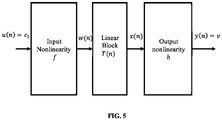
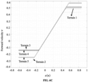
- the non-linear model (alternatively referred as an offline model and may be interchangeably used herein after) could be but not limited to a Hammerstein wiener model. FIG.
- the Hammerstein-Wiener model describes a dynamic system using dynamic linear block in series with static nonlinear blocks.
- the Hammerstein-Wiener model comprises an input non-linearity block, a linear block, and an output non-linearity block.
- the input non-linearity block of the Hammerstein-Wiener model captures nonlinearity present in input data which is referred as input nonlinearity and represented by a non-linear function f .
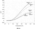
- FIGS. 6A through 6C show graphs depicting outputs of different blocks of the Hammerstein-Weiner model for different terrains, in accordance with some embodiments of the present disclosure.
- the non-linearity in command input signal c 1 is captured by a piece-wise linear function.
- c 1 ( n ) represents n th instant of commanded input c 1 and coefficients a 2 , a 1 and a 0 ⁇ R define non-linearity behavior that depend on factors such as terrain, payload, and the like.
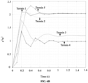
- output of the input non-linearity block is provided as input to the linear block of the Hammerstein-Weiner model.
- the linear block of the Hammerstein-Weiner model is a discrete transfer function that represents dynamic component of the experimental model.
- T(z) represents transfer function expressed in z domain.
- the transfer function T ( z ) transforms W ( z ) to X ( z ) as shown in equation (5) and (6) provided below as:
- W ( z ) and X ( z ) represent z transforms of discrete signals w ( n ) and x.
- coefficients b 2 , b 3 , d 1 , d 2 , and d 3 ⁇ R define dynamic response of the Hammerstein-Weiner model to input w ( n ). Further, values of these coefficients depend on factors such as terrain, payload, and the like.
- the non-linear function h is referred as output non-linearity since it acts on the output of the linear block.
- This output non-linearity is configured as a saturation function in the method of proposed disclosure as shown in FIG. 6C to model velocity saturation of the vehicle.
- y n ⁇ x n if v min ⁇ x n ⁇ v max v max if x n > v max v min if x n ⁇ v min
- v max and v min represent maximum velocity that the vehicle can attain in forward and backward direction respectively. From experimentation, it was observed that these saturation values occur when wheel motors of the vehicle reach their maximum capability. Hence, it was ensured during experiments that vehicle is operated in linear region of y n .
- c 1 represents time synchronized command input signal for the forward motion of the vehicle
- g ( c 1 ) refer to the experimental model which maps c 1 to the forward velocity v of the vehicle.
- the generated experimental model does not adapt to change in one or more factors such as terrain, vehicle payload, and challenging environmental conditions during real time operation.
- the system 104 of the present disclosure for indoor navigation having smooth terrain, gives value of position of the vehicle as 1km for a forward velocity of 1m/s, 2km for forward velocity of 2m/s.
- the system 104 may provide value of the position of the vehicle as 1km for a forward velocity of 2m/s, 2km for forward velocity of 5m/s.
- the generated experimental model does not adapt to change in these factors while changing from indoor navigation to outdoor navigation which may lead to inaccurate results.
- EKF Extended Kalman Filter
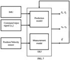
- FIG. 7 illustrates a functional block diagram of the EKF framework for estimation of the one or motion parameters in real time, in accordance with some embodiment of the present disclosure.
- the EKF framework comprises a prediction model and a measurement model.
- the generated experimental model is used as the prediction model which receives time synchronized command inputs signals and orientation information of the vehicle obtained from the inertial measurement unit as input and estimates position coordinates P x , P y and velocity coordinates v x , v y of the vehicle.
- p x ( n ), p y ( n ) represent position coordinates of body of the vehicle in the reference frame, at n th time instant
- v ( n ), v ( n - 1), and v ( n - 2) represent the forward velocity of the vehicle at n th , n - 1 th , and n - 2 th time instant respectively
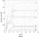
- K ( n ) [ K 1 ( n ), K 2 ( n ), K 3 ( n ), K 4 ( n ), K 5 ( n ), K 6 ( n ), K 7 ( n )] represents the set of model parameters of the prediction model.
- T refers to sampling period
- ⁇ ( n ) refers to orientation information of the vehicle obtained from the inertial measurement unit.
- jacobian of the prediction model is determined which is expressed by equation (14) provided below as: 1 0 T cos ⁇ n 0 0 0 0 0 0 0 0 0 0 1 T sin ⁇ n 0 0 0 0 0 0 0 0 0 0 K 5 K 6 K 7 c 1 n ⁇ 2 2 c 1 n ⁇ 2 c 1 n ⁇ 3 2 c 1 n ⁇ 3 v n v n ⁇ 1 v n ⁇ 2 0 0 0 1 0 0 0 0 0 0 0 0 0 0 0 0 0 0 0 1 0 0 0 0 0 0 0 0 0 0 0 0 1 0 0 0 0 0 0 0 0 0 0 0 0 0 0 1 0 0 0 0 0 0 0 0 0 0 0 0 0
- the one or more hardware processors 206 perform, using a plurality of data obtained from one or more sensors, a validation of the estimated value of the one or more motion parameters.
- the position coordinates P x , P y and velocity coordinates v x , v y of the vehicle estimated from the prediction model of the EKF framework are referred as the one or more motion parameters.
- the one or more sensors used for validation include position sensors and velocity sensors.
- the step of validation is performed whenever data obtained from the one or more sensors is available. The data obtained from the one or more sensors is provided to the measurement model of the EKF framework.
- the validation is performed by computing an error between the plurality of data obtained from the one or more sensors and measurements of the one or more motion parameters obtained from a ground truth system.
- position measurements are obtained from the ground truth system and compared with the position data obtained from position sensors. The position measurements obtained from the ground truth system are transformed to the reference frame and used as measurement updates.
- I 2 and 0 2 represent Identity and Null matrix of order 2, respectively.
- the error computed between position data obtained from the position sensor and measurements updates of the ground truth system is expressed as ( p m - H ( n ) z ( n )).
- the one or more hardware processors 206 adaptively update the experimental model to estimate an updated value of the one or more motion parameters based on the validation. For example, whenever the plurality of data from the one or more sensors is available, the error is computed. In case of no error, the system 104 is not required to adapt to any changes to provide accurate results. However, in presence of error, the experimental model adapts to the changes and estimates the updated value of the one or more motion parameters. The updated one or more motion parameters are further learnt and fed back to the prediction model of the EKF framework to provide continuous updates and learning of K in the real time.
- the step of adaptively updating the experimental model is performed using the computed error and a gain parameter as expressed in equation (16) and equation (17) provided below:
- G ( n ) represents the gain parameter which is also known as kalman gain at n th instant
- P ( n ) represents process covariance matrix for the position data obtained from position sensors p m .
- the process covariance matrix provides a measure of accuracy of the prediction model.
- R represents noise covariance matrix for the position data obtained from position sensors p m .
- the noise covariance matrix provides a measure of accuracy of the plurality of data obtained from the one or more sensors.
- the step of adaptively updating the experimental model reduces inaccuracy introduced due to the one or more factors such as change in terrain, change in payload of vehicle, and the like.
- the differential drive vehicle used in the system of present disclosure comprises a RGB- depth camera for position estimation using exteroceptive sensing. Additionally, a low-cost inertial measurement unit (IMU) was employed for sensing orientation of the vehicle. Further, for locomotion, one differential drive with four 6V DC motors was used in the vehicle. The DC motors were connected to a first computation system (known in the art) via a motor driver circuit. Also, a second computation system (known in the art) was mounted upon the vehicle to make it functional and an ad hoc wireless network was created to interface the first computation system and the second computation system. A known ground truth system has been used to capture actual pose of the vehicle which is used as Ground truth for experimentation. Matlab software was used for computation of the experimental model and non-linear Hammerstein-wiener model. Further, the implementation and testing was performed using ROS platform on the second computation system.
- IMU inertial measurement unit
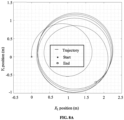
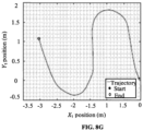
- the differential drive vehicle was moved on different surfaces and trajectories.
- the trajectories varied from straight line to sharp turns and the velocities varied from 10 cm/sec to up to 80 cm/sec.
- Many experiments were performed including a variety of turning radius and frequent accelerations and decelerations, making the behavior of the vehicle highly dynamic. Motion of the vehicle remained consistent with navigation of the vehicle in real life scenarios using the method of present disclosure.
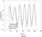
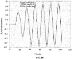
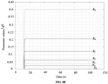
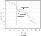
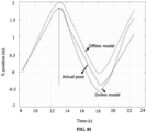
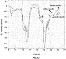
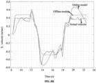
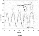
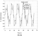
- FIGS. 8A through 8R show graphs illustrating experimental results for control command based adaptive system and method for estimating motion parameters of differential drive vehicles, in accordance with some embodiments of the present disclosure.
- the efficiency of the method of present disclosure is demonstrated by performing three different experiments. The three different experiments are described below:
- Table 1 provides root mean square (RMS) errors in estimated position and velocity for the three experiments using online and offline models.
- RMS root mean square
- the method of the present disclosure provides accurate results for localization or estimating the motion parameters of the differential drive vehicle with minimum use of extroceptive sensors. Reduction in the number of sensors leads to reduced cost. Also, the system of the present disclosure adapts to change in different factors such as terrain, payload change, and the like by continuous learning.
- the hardware device can be any kind of device which can be programmed including e.g. any kind of computer like a server or a personal computer, or the like, or any combination thereof.
- the device may also include means which could be e.g. hardware means like e.g. an applicationspecific integrated circuit (ASIC), a field-programmable gate array (FPGA), or a combination of hardware and software means, e.g.
- ASIC applicationspecific integrated circuit
- FPGA field-programmable gate array
- the means can include both hardware means and software means.
- the method embodiments described herein could be implemented in hardware and software.
- the device may also include software means.
- the embodiments may be implemented on different hardware devices, e.g. using a plurality of CPUs.
- the embodiments herein can comprise hardware and software elements.
- the embodiments that are implemented in software include but are not limited to, firmware, resident software, microcode, etc.
- the functions performed by various modules described herein may be implemented in other modules or combinations of other modules.
- a computer-usable or computer readable medium can be any apparatus that can comprise, store, communicate, propagate, or transport the program for use by or in connection with the instruction execution system, apparatus, or device.
- a computer-readable storage medium refers to any type of physical memory on which information or data readable by a processor may be stored.
- a computer-readable storage medium may store instructions for execution by one or more processors, including instructions for causing the processor(s) to perform steps or stages consistent with the embodiments described herein.
- the term "computer-readable medium” should be understood to include tangible items and exclude carrier waves and transient signals, i.e., be non-transitory. Examples include random access memory (RAM), read-only memory (ROM), volatile memory, nonvolatile memory, hard drives, CD ROMs, DVDs, flash drives, disks, and any other known physical storage media.
Landscapes
- Engineering & Computer Science (AREA)
- Theoretical Computer Science (AREA)
- Data Mining & Analysis (AREA)
- Physics & Mathematics (AREA)
- General Physics & Mathematics (AREA)
- Evolutionary Computation (AREA)
- Computer Vision & Pattern Recognition (AREA)
- General Engineering & Computer Science (AREA)
- Artificial Intelligence (AREA)
- Life Sciences & Earth Sciences (AREA)
- Evolutionary Biology (AREA)
- Bioinformatics & Computational Biology (AREA)
- Bioinformatics & Cheminformatics (AREA)
- Software Systems (AREA)
- Robotics (AREA)
- Mechanical Engineering (AREA)
- Mathematical Physics (AREA)
- Computing Systems (AREA)
- Medical Informatics (AREA)
- Aviation & Aerospace Engineering (AREA)
- Radar, Positioning & Navigation (AREA)
- Remote Sensing (AREA)
- Automation & Control Theory (AREA)
- Control Of Position, Course, Altitude, Or Attitude Of Moving Bodies (AREA)
- Control Of Driving Devices And Active Controlling Of Vehicle (AREA)
Claims (12)
- Prozessorimplementiertes Verfahren, umfassend:Eingeben (302), über den einen oder die mehreren Hardwareprozessoren, eines oder mehrerer zeitsynchronisierter Befehlseingabesignale an ein sich bewegendes Differentialantriebsfahrzeug;Bestimmen (304), auf der Grundlage des einen oder der mehreren zeitsynchronisierten Befehlseingabesignale, einer entsprechenden Änderung eines oder mehrerer Bewegungsparameter des sich bewegenden Differentialantriebsfahrzeugs;Trainieren (306) eines nichtlinearen Modells unter Verwendung des einen oder der mehreren zeitsynchronisierten Befehlseingabesignale und der bestimmten entsprechenden Änderung des einen oder der mehreren Bewegungsparameter, wobei das nichtlineare Modell ein Hammerstein-Wiener-Modell ist, das einen statischen nichtlinearen Eingangsblock, einen dynamischen linearen Block und einen statischen nichtlinearen Ausgangsblock in Reihe umfasst, wobei der statische nichtlineare Eingangsblock ein in dem einen oder den mehreren zeitsynchronisierten Befehlseingabesignalen vorhandenes Nichtlinearitätsverhalten erfasst, wobei der dynamische lineare Block eine dynamische Antwort des Hammerstein-Wiener-Modells erfasst und wobei der statische nichtlineare Ausgangsblock eine in der dynamischen Antwort des Hammerstein-Wiener-Modells vorhandene Nichtlinearität erfasst;Erzeugen (308), unter Verwendung des trainierten nichtlinearen Modells, eines experimentellen Modells durch Berechnen einer Abbildungsfunktion zwischen dem einen oder den mehreren zeitsynchronisierten Befehlseingabesignalen und dem einen oder den mehreren Bewegungsparametern des sich bewegenden Differentialantriebsfahrzeugs, wobei der eine oder die mehreren Bewegungsparameter Positionskoordinaten und Geschwindigkeitskoordinaten des sich bewegenden Differentialantriebsfahrzeugs umfassen;Schätzen (310), unter Verwendung des erzeugten experimentellen Modells, des Wertes des einen oder der mehreren Bewegungsparameter auf der Grundlage des einen oder der mehreren eingehenden zeitsynchronisierten Befehlseingabesignale und von Orientierungsinformationen, die von einer Trägheitsmesseinheit des sich bewegenden Differentialantriebsfahrzeugs erhalten werden;Durchführen (312), unter Verwendung einer Vielzahl von Daten, die von einem oder mehreren Sensoren erhalten wurden, einer Validierung des geschätzten Wertes des einen oder der mehreren Bewegungsparameter; undadaptives Aktualisieren (314) des experimentellen Modells zum Schätzen eines aktualisierten Wertes des einen oder der mehreren Bewegungsparameter auf der Grundlage der Validierung, indem Modellparameter in Echtzeit gelernt werden.
- Prozessorimplementiertes Verfahren nach Anspruch 1, wobei der eine oder die mehreren Sensoren, die zur Validierung verwendet werden, Positionssensoren und Geschwindigkeitssensoren beinhalten.
- Prozessorimplementiertes Verfahren nach Anspruch 1, wobei die Validierung durch Berechnen eines Fehlers zwischen der Vielzahl von Daten, die von dem einen oder den mehreren Sensoren erhalten wurden, und Messungen eines oder mehrerer Bewegungsparameter, die von einem Bodenreferenzsystem erhalten wurden, durchgeführt wird.
- Prozessorimplementiertes Verfahren nach Anspruch 1, wobei der Schritt des adaptiven Aktualisierens des experimentellen Modells unter Verwendung des berechneten Fehlers und eines Verstärkungsparameters durchgeführt wird.
- System (104), umfassend:einen Speicher (202);eine oder mehrere Kommunikationsschnittstellen (204); undeinen oder mehrere Hardwareprozessoren (206), die über die eine oder die mehreren Kommunikationsschnittstellen (204) mit dem Speicher (202) gekoppelt sind, wobei der eine oder die mehreren Hardwareprozessoren (206) für folgende Vorgänge ausgelegt sind:Eingeben eines oder mehrerer zeitsynchronisierter Befehlseingabesignale an ein sich bewegendes Differentialantriebsfahrzeug;Bestimmen, auf der Grundlage des einen oder der mehreren zeitsynchronisierten Befehlseingabesignale, einer entsprechenden Änderung eines oder mehrerer Bewegungsparameter des sich bewegenden Differentialantriebsfahrzeugs;Trainieren eines nichtlinearen Modells unter Verwendung des einen oder der mehreren zeitsynchronisierten Befehlseingabesignale und der bestimmten entsprechenden Änderung des einen oder der mehreren Bewegungsparameter, wobei das nichtlineare Modell ein Hammerstein-Wiener-Modell ist, das einen statischen nichtlinearen Eingangsblock, einen dynamischen linearen Block und einen statischen nichtlinearen Ausgangsblock in Reihe umfasst, wobei der statische nichtlineare Eingangsblock ein in dem einen oder den mehreren zeitsynchronisierten Befehlseingabesignalen vorhandenes Nichtlinearitätsverhalten erfasst, wobei der dynamische lineare Block eine dynamische Antwort des Hammerstein-Wiener-Modells erfasst und wobei der statische nichtlineare Ausgangsblock eine in der dynamischen Antwort des Hammerstein-Wiener-Modells vorhandene Nichtlinearität erfasst;Erzeugen, unter Verwendung des trainierten nichtlinearen Modells, eines experimentellen Modells durch Berechnen einer Abbildungsfunktion zwischen dem einen oder mehreren zeitsynchronisierten Befehlseingabesignalen und dem einen oder den mehreren Bewegungsparametern des sich bewegenden Differentialantriebsfahrzeugs, wobei der eine oder die mehreren Bewegungsparameter Positionskoordinaten und Geschwindigkeitskoordinaten des sich bewegenden Differentialantriebsfahrzeugs umfassen;Schätzen, unter Verwendung des erzeugten experimentellen Modells, des Wertes des einen oder der mehreren Bewegungsparameter auf der Grundlage des einen oder der mehreren eingehenden zeitsynchronisierten Befehlseingabesignale und von Orientierungsinformationen, die von einer Trägheitsmesseinheit des sich bewegenden Differentialantriebsfahrzeugs erhalten werden;Durchführen, unter Verwendung einer Vielzahl von Daten, die von einem oder mehreren Sensoren erhalten wurden, einer Validierung des geschätzten Wertes des einen oder der mehreren Bewegungsparameter; undadaptives Aktualisieren des experimentellen Modells zum Schätzen eines aktualisierten Wertes des einen oder der mehreren Bewegungsparameter auf der Grundlage der Validierung, indem Modellparameter in Echtzeit gelernt werden.
- System nach Anspruch 5, wobei der eine oder die mehreren Sensoren, die zur Validierung verwendet werden, Positionssensoren und Geschwindigkeitssensoren beinhalten.
- System nach Anspruch 5, wobei die Validierung durch Berechnen eines Fehlers zwischen der Vielzahl von Daten, die von dem einen oder den mehreren Sensoren erhalten wurden, und Messungen eines oder mehrerer Bewegungsparameter, die von einem Bodenreferenzsystem erhalten wurden, durchgeführt wird.
- System nach Anspruch 5, wobei der Schritt des adaptiven Aktualisierens des experimentellen Modells unter Verwendung des berechneten Fehlers und eines Verstärkungsparameters durchgeführt wird.
- Ein oder mehrere nichtflüchtige, maschinenlesbare Informationsspeichermedien, die eine oder mehrere Anweisungen umfassen, die bei ihrer Ausführung durch einen oder mehrere Hardwareprozessoren folgende Vorgänge bewirken:Eingeben, über den einen oder die mehreren Hardwareprozessoren, eines oder mehrerer zeitsynchronisierter Befehlseingabesignale an ein sich bewegendes Differentialantriebsfahrzeug;Bestimmen, auf der Grundlage des einen oder der mehreren zeitsynchronisierten Befehlseingabesignale, einer entsprechenden Änderung eines oder mehrerer Bewegungsparameter des sich bewegenden Differentialantriebsfahrzeugs;Trainieren eines nichtlinearen Modells unter Verwendung des einen oder der mehreren zeitsynchronisierten Befehlseingabesignale und der bestimmten entsprechenden Änderung des einen oder der mehreren Bewegungsparameter, wobei das nichtlineare Modell ein Hammerstein-Wiener-Modell ist, das einen statischen nichtlinearen Eingangsblock, einen dynamischen linearen Block und einen statischen nichtlinearen Ausgangsblock in Reihe umfasst, wobei der statische nichtlineare Eingangsblock ein in dem einen oder den mehreren zeitsynchronisierten Befehlseingabesignalen vorhandenes Nichtlinearitätsverhalten erfasst, wobei der dynamische lineare Block eine dynamische Antwort des Hammerstein-Wiener-Modells erfasst und wobei der statische nichtlineare Ausgangsblock eine in der dynamischen Antwort des Hammerstein-Wiener-Modells vorhandene Nichtlinearität erfasst;Erzeugen, unter Verwendung des trainierten nichtlinearen Modells, eines experimentellen Modells durch Berechnen einer Abbildungsfunktion zwischen dem einen oder mehreren zeitsynchronisierten Befehlseingabesignalen und dem einen oder den mehreren Bewegungsparametern des sich bewegenden Differentialantriebsfahrzeugs, wobei der eine oder die mehreren Bewegungsparameter Positionskoordinaten und Geschwindigkeitskoordinaten des sich bewegenden Differentialantriebsfahrzeugs umfassen;Schätzen, unter Verwendung des erzeugten experimentellen Modells, des Wertes des einen oder der mehreren Bewegungsparameter auf der Grundlage des einen oder der mehreren eingehenden zeitsynchronisierten Befehlseingabesignale und von Orientierungsinformationen, die von einer Trägheitsmesseinheit des sich bewegenden Differentialantriebsfahrzeugs erhalten werden;Durchführen, unter Verwendung einer Vielzahl von Daten, die von einem oder mehreren Sensoren erhalten wurden, einer Validierung des geschätzten Wertes des einen oder der mehreren Bewegungsparameter; undadaptives Aktualisieren des experimentellen Modells zum Schätzen eines aktualisierten Wertes des einen oder der mehreren Bewegungsparameter auf der Grundlage der Validierung, indem Modellparameter in Echtzeit gelernt werden.
- Ein oder mehrere nichtflüchtige maschinenlesbare Informationsspeichermedien nach Anspruch 9, wobei der eine oder die mehreren Sensoren, die zur Validierung verwendet werden, Positionssensoren und Geschwindigkeitssensoren beinhalten.
- Ein oder mehrere nichtflüchtige maschinenlesbare Informationsspeichermedien nach Anspruch 9, wobei die Validierung durch Berechnen eines Fehlers zwischen der Vielzahl von Daten, die von dem einen oder den mehreren Sensoren erhalten wurden, und Messungen eines oder mehrerer Bewegungsparameter, die von einem Bodenreferenzsystem erhalten wurden, durchgeführt wird.
- Ein oder mehrere nichtflüchtige maschinenlesbare Informationsspeichermedien nach Anspruch 9, wobei der Schritt des adaptiven Aktualisierens des experimentellen Modells unter Verwendung des berechneten Fehlers und eines Verstärkungsparameters durchgeführt wird.
Applications Claiming Priority (1)
| Application Number | Priority Date | Filing Date | Title |
|---|---|---|---|
| IN201921039285 | 2019-09-27 |
Publications (2)
| Publication Number | Publication Date |
|---|---|
| EP3797939A1 EP3797939A1 (de) | 2021-03-31 |
| EP3797939B1 true EP3797939B1 (de) | 2023-03-01 |
Family
ID=72148001
Family Applications (1)
| Application Number | Title | Priority Date | Filing Date |
|---|---|---|---|
| EP20191743.2A Active EP3797939B1 (de) | 2019-09-27 | 2020-08-19 | Steuerbefehlbasiertes adaptives system und verfahren zur schätzung von bewegungsparametern von fahrzeugen mit differentialantrieb |
Country Status (2)
| Country | Link |
|---|---|
| US (1) | US11958194B2 (de) |
| EP (1) | EP3797939B1 (de) |
Families Citing this family (2)
| Publication number | Priority date | Publication date | Assignee | Title |
|---|---|---|---|---|
| KR102889855B1 (ko) * | 2020-11-03 | 2025-11-26 | 하치도리 로보틱스 프라이빗 리미티드 | 운행공간을 통하여 실시간으로 자율개체를 운행하기 위한 시스템 및 방법 |
| US20220179424A1 (en) * | 2020-12-09 | 2022-06-09 | Regents Of The University Of Minnesota | Systems and methods for autonomous navigation on sidewalks in various conditions |
Family Cites Families (12)
| Publication number | Priority date | Publication date | Assignee | Title |
|---|---|---|---|---|
| US5416712A (en) | 1993-05-28 | 1995-05-16 | Trimble Navigation Limited | Position and velocity estimation system for adaptive weighting of GPS and dead-reckoning information |
| US9818136B1 (en) * | 2003-02-05 | 2017-11-14 | Steven M. Hoffberg | System and method for determining contingent relevance |
| US8874477B2 (en) * | 2005-10-04 | 2014-10-28 | Steven Mark Hoffberg | Multifactorial optimization system and method |
| US8751151B2 (en) * | 2012-06-12 | 2014-06-10 | Trx Systems, Inc. | System and method for localizing a trackee at a location and mapping the location using inertial sensor information |
| US8126642B2 (en) | 2008-10-24 | 2012-02-28 | Gray & Company, Inc. | Control and systems for autonomously driven vehicles |
| US8374785B2 (en) | 2010-01-28 | 2013-02-12 | Eride, Inc. | Tightly coupled GPS and dead-reckoning vehicle navigation |
| KR101628427B1 (ko) | 2012-12-17 | 2016-06-08 | 주식회사 만도 | 카메라를 이용한 추측항법 기반 네비게이션 시스템 및 그 제어방법 |
| WO2015179632A1 (en) * | 2014-05-22 | 2015-11-26 | Scheffler Lee J | Methods and systems for neural and cognitive processing |
| US10411356B2 (en) * | 2016-12-08 | 2019-09-10 | At&T Intellectual Property I, L.P. | Apparatus and methods for selectively targeting communication devices with an antenna array |
| US11422253B2 (en) * | 2018-11-19 | 2022-08-23 | Tdk Corportation | Method and system for positioning using tightly coupled radar, motion sensors and map information |
| US11010921B2 (en) * | 2019-05-16 | 2021-05-18 | Qualcomm Incorporated | Distributed pose estimation |
| US12114990B2 (en) * | 2020-01-21 | 2024-10-15 | Washington University | Systems and methods for electromyometrial imaging |
-
2020
- 2020-08-19 EP EP20191743.2A patent/EP3797939B1/de active Active
- 2020-08-24 US US17/000,908 patent/US11958194B2/en active Active
Also Published As
| Publication number | Publication date |
|---|---|
| EP3797939A1 (de) | 2021-03-31 |
| US20210097437A1 (en) | 2021-04-01 |
| US11958194B2 (en) | 2024-04-16 |
Similar Documents
| Publication | Publication Date | Title |
|---|---|---|
| US20240312061A1 (en) | High-precision odometry estimation method based on double-layer filtering framework | |
| Erfani et al. | Comparison of two data fusion methods for localization of wheeled mobile robot in farm conditions | |
| Marin et al. | Event-based localization in ackermann steering limited resource mobile robots | |
| Cheein et al. | Trajectory tracking controller design for unmanned vehicles: A new methodology | |
| Klančar et al. | A control strategy for platoons of differential drive wheeled mobile robot | |
| Taghia et al. | A sliding mode controller with a nonlinear disturbance observer for a farm vehicle operating in the presence of wheel slip | |
| Ismael et al. | Nonlinear model predictive control-based collision avoidance for mobile robot | |
| Lu et al. | Motion predicting of autonomous tracked vehicles with online slip model identification | |
| CN111708010B (zh) | 一种可移动设备的定位方法、装置、系统及可移动设备 | |
| Dang et al. | Tightly-coupled data fusion of VINS and odometer based on wheel slip estimation | |
| EP3797939B1 (de) | Steuerbefehlbasiertes adaptives system und verfahren zur schätzung von bewegungsparametern von fahrzeugen mit differentialantrieb | |
| Wen et al. | G²VD Planner: Efficient Motion Planning With Grid-Based Generalized Voronoi Diagrams | |
| Ren et al. | Spherical robot: A novel robot for exploration in harsh unknown environments | |
| Wang et al. | Terrain adaptive estimation of instantaneous centres of rotation for tracked robots | |
| EP4435549B1 (de) | Roboternavigation mit gleichzeitiger planung und lernen des lokalen pfades | |
| CN113448338B (zh) | 机器人控制方法、机器人、计算机程序产品和存储介质 | |
| Biswas et al. | Validating observer based on-line slip estimation for improved navigation by a mobile robot | |
| Shin et al. | Multi-robot relative pose estimation in se (2) with observability analysis: A comparison of extended kalman filtering and robust pose graph optimization | |
| Pentzer et al. | On‐line estimation of power model parameters for skid‐steer robots with applications in mission energy use prediction | |
| Ahluwalia et al. | Construction and benchmark of an autonomous tracked mobile robot system | |
| Oonk et al. | Extended kalman filter for improved navigation with fault awareness | |
| Tisland et al. | How extending the kinematic model affects path following in off-road terrain for differential drive UGVs | |
| Murali | Perception-aware planning for differentially flat robots | |
| Wahlqvist | A comparison of motion priors for EKF-SLAM in autonomous race cars | |
| Dos Santos et al. | Integrating Visual and Encoder Data for Enhanced Navigation in Mecanum-Wheeled Robots via Extended Kalman Filter |
Legal Events
| Date | Code | Title | Description |
|---|---|---|---|
| PUAI | Public reference made under article 153(3) epc to a published international application that has entered the european phase |
Free format text: ORIGINAL CODE: 0009012 |
|
| STAA | Information on the status of an ep patent application or granted ep patent |
Free format text: STATUS: THE APPLICATION HAS BEEN PUBLISHED |
|
| AK | Designated contracting states |
Kind code of ref document: A1 Designated state(s): AL AT BE BG CH CY CZ DE DK EE ES FI FR GB GR HR HU IE IS IT LI LT LU LV MC MK MT NL NO PL PT RO RS SE SI SK SM TR |
|
| AX | Request for extension of the european patent |
Extension state: BA ME |
|
| STAA | Information on the status of an ep patent application or granted ep patent |
Free format text: STATUS: REQUEST FOR EXAMINATION WAS MADE |
|
| 17P | Request for examination filed |
Effective date: 20210930 |
|
| RBV | Designated contracting states (corrected) |
Designated state(s): AL AT BE BG CH CY CZ DE DK EE ES FI FR GB GR HR HU IE IS IT LI LT LU LV MC MK MT NL NO PL PT RO RS SE SI SK SM TR |
|
| RIC1 | Information provided on ipc code assigned before grant |
Ipc: G05D 1/02 20200101ALI20220719BHEP Ipc: B25J 9/16 20060101AFI20220719BHEP |
|
| GRAP | Despatch of communication of intention to grant a patent |
Free format text: ORIGINAL CODE: EPIDOSNIGR1 |
|
| STAA | Information on the status of an ep patent application or granted ep patent |
Free format text: STATUS: GRANT OF PATENT IS INTENDED |
|
| INTG | Intention to grant announced |
Effective date: 20220919 |
|
| GRAS | Grant fee paid |
Free format text: ORIGINAL CODE: EPIDOSNIGR3 |
|
| GRAA | (expected) grant |
Free format text: ORIGINAL CODE: 0009210 |
|
| STAA | Information on the status of an ep patent application or granted ep patent |
Free format text: STATUS: THE PATENT HAS BEEN GRANTED |
|
| AK | Designated contracting states |
Kind code of ref document: B1 Designated state(s): AL AT BE BG CH CY CZ DE DK EE ES FI FR GB GR HR HU IE IS IT LI LT LU LV MC MK MT NL NO PL PT RO RS SE SI SK SM TR |
|
| REG | Reference to a national code |
Ref country code: GB Ref legal event code: FG4D |
|
| REG | Reference to a national code |
Ref country code: CH Ref legal event code: EP Ref country code: AT Ref legal event code: REF Ref document number: 1550659 Country of ref document: AT Kind code of ref document: T Effective date: 20230315 |
|
| REG | Reference to a national code |
Ref country code: DE Ref legal event code: R096 Ref document number: 602020008417 Country of ref document: DE |
|
| REG | Reference to a national code |
Ref country code: IE Ref legal event code: FG4D |
|
| REG | Reference to a national code |
Ref country code: NL Ref legal event code: FP |
|
| REG | Reference to a national code |
Ref country code: LT Ref legal event code: MG9D |
|
| P01 | Opt-out of the competence of the unified patent court (upc) registered |
Effective date: 20230526 |
|
| PG25 | Lapsed in a contracting state [announced via postgrant information from national office to epo] |
Ref country code: RS Free format text: LAPSE BECAUSE OF FAILURE TO SUBMIT A TRANSLATION OF THE DESCRIPTION OR TO PAY THE FEE WITHIN THE PRESCRIBED TIME-LIMIT Effective date: 20230301 Ref country code: NO Free format text: LAPSE BECAUSE OF FAILURE TO SUBMIT A TRANSLATION OF THE DESCRIPTION OR TO PAY THE FEE WITHIN THE PRESCRIBED TIME-LIMIT Effective date: 20230601 Ref country code: LV Free format text: LAPSE BECAUSE OF FAILURE TO SUBMIT A TRANSLATION OF THE DESCRIPTION OR TO PAY THE FEE WITHIN THE PRESCRIBED TIME-LIMIT Effective date: 20230301 Ref country code: LT Free format text: LAPSE BECAUSE OF FAILURE TO SUBMIT A TRANSLATION OF THE DESCRIPTION OR TO PAY THE FEE WITHIN THE PRESCRIBED TIME-LIMIT Effective date: 20230301 Ref country code: HR Free format text: LAPSE BECAUSE OF FAILURE TO SUBMIT A TRANSLATION OF THE DESCRIPTION OR TO PAY THE FEE WITHIN THE PRESCRIBED TIME-LIMIT Effective date: 20230301 Ref country code: ES Free format text: LAPSE BECAUSE OF FAILURE TO SUBMIT A TRANSLATION OF THE DESCRIPTION OR TO PAY THE FEE WITHIN THE PRESCRIBED TIME-LIMIT Effective date: 20230301 |
|
| REG | Reference to a national code |
Ref country code: AT Ref legal event code: MK05 Ref document number: 1550659 Country of ref document: AT Kind code of ref document: T Effective date: 20230301 |
|
| PG25 | Lapsed in a contracting state [announced via postgrant information from national office to epo] |
Ref country code: SE Free format text: LAPSE BECAUSE OF FAILURE TO SUBMIT A TRANSLATION OF THE DESCRIPTION OR TO PAY THE FEE WITHIN THE PRESCRIBED TIME-LIMIT Effective date: 20230301 Ref country code: PL Free format text: LAPSE BECAUSE OF FAILURE TO SUBMIT A TRANSLATION OF THE DESCRIPTION OR TO PAY THE FEE WITHIN THE PRESCRIBED TIME-LIMIT Effective date: 20230301 Ref country code: GR Free format text: LAPSE BECAUSE OF FAILURE TO SUBMIT A TRANSLATION OF THE DESCRIPTION OR TO PAY THE FEE WITHIN THE PRESCRIBED TIME-LIMIT Effective date: 20230602 Ref country code: FI Free format text: LAPSE BECAUSE OF FAILURE TO SUBMIT A TRANSLATION OF THE DESCRIPTION OR TO PAY THE FEE WITHIN THE PRESCRIBED TIME-LIMIT Effective date: 20230301 |
|
| PG25 | Lapsed in a contracting state [announced via postgrant information from national office to epo] |
Ref country code: SM Free format text: LAPSE BECAUSE OF FAILURE TO SUBMIT A TRANSLATION OF THE DESCRIPTION OR TO PAY THE FEE WITHIN THE PRESCRIBED TIME-LIMIT Effective date: 20230301 Ref country code: RO Free format text: LAPSE BECAUSE OF FAILURE TO SUBMIT A TRANSLATION OF THE DESCRIPTION OR TO PAY THE FEE WITHIN THE PRESCRIBED TIME-LIMIT Effective date: 20230301 Ref country code: PT Free format text: LAPSE BECAUSE OF FAILURE TO SUBMIT A TRANSLATION OF THE DESCRIPTION OR TO PAY THE FEE WITHIN THE PRESCRIBED TIME-LIMIT Effective date: 20230703 Ref country code: EE Free format text: LAPSE BECAUSE OF FAILURE TO SUBMIT A TRANSLATION OF THE DESCRIPTION OR TO PAY THE FEE WITHIN THE PRESCRIBED TIME-LIMIT Effective date: 20230301 Ref country code: CZ Free format text: LAPSE BECAUSE OF FAILURE TO SUBMIT A TRANSLATION OF THE DESCRIPTION OR TO PAY THE FEE WITHIN THE PRESCRIBED TIME-LIMIT Effective date: 20230301 Ref country code: AT Free format text: LAPSE BECAUSE OF FAILURE TO SUBMIT A TRANSLATION OF THE DESCRIPTION OR TO PAY THE FEE WITHIN THE PRESCRIBED TIME-LIMIT Effective date: 20230301 |
|
| PG25 | Lapsed in a contracting state [announced via postgrant information from national office to epo] |
Ref country code: SK Free format text: LAPSE BECAUSE OF FAILURE TO SUBMIT A TRANSLATION OF THE DESCRIPTION OR TO PAY THE FEE WITHIN THE PRESCRIBED TIME-LIMIT Effective date: 20230301 Ref country code: IS Free format text: LAPSE BECAUSE OF FAILURE TO SUBMIT A TRANSLATION OF THE DESCRIPTION OR TO PAY THE FEE WITHIN THE PRESCRIBED TIME-LIMIT Effective date: 20230701 |
|
| REG | Reference to a national code |
Ref country code: DE Ref legal event code: R097 Ref document number: 602020008417 Country of ref document: DE |
|
| PLBE | No opposition filed within time limit |
Free format text: ORIGINAL CODE: 0009261 |
|
| STAA | Information on the status of an ep patent application or granted ep patent |
Free format text: STATUS: NO OPPOSITION FILED WITHIN TIME LIMIT |
|
| PG25 | Lapsed in a contracting state [announced via postgrant information from national office to epo] |
Ref country code: SI Free format text: LAPSE BECAUSE OF FAILURE TO SUBMIT A TRANSLATION OF THE DESCRIPTION OR TO PAY THE FEE WITHIN THE PRESCRIBED TIME-LIMIT Effective date: 20230301 Ref country code: DK Free format text: LAPSE BECAUSE OF FAILURE TO SUBMIT A TRANSLATION OF THE DESCRIPTION OR TO PAY THE FEE WITHIN THE PRESCRIBED TIME-LIMIT Effective date: 20230301 |
|
| 26N | No opposition filed |
Effective date: 20231204 |
|
| PG25 | Lapsed in a contracting state [announced via postgrant information from national office to epo] |
Ref country code: MC Free format text: LAPSE BECAUSE OF FAILURE TO SUBMIT A TRANSLATION OF THE DESCRIPTION OR TO PAY THE FEE WITHIN THE PRESCRIBED TIME-LIMIT Effective date: 20230301 |
|
| PG25 | Lapsed in a contracting state [announced via postgrant information from national office to epo] |
Ref country code: MC Free format text: LAPSE BECAUSE OF FAILURE TO SUBMIT A TRANSLATION OF THE DESCRIPTION OR TO PAY THE FEE WITHIN THE PRESCRIBED TIME-LIMIT Effective date: 20230301 |
|
| PG25 | Lapsed in a contracting state [announced via postgrant information from national office to epo] |
Ref country code: LU Free format text: LAPSE BECAUSE OF NON-PAYMENT OF DUE FEES Effective date: 20230819 |
|
| PG25 | Lapsed in a contracting state [announced via postgrant information from national office to epo] |
Ref country code: LU Free format text: LAPSE BECAUSE OF NON-PAYMENT OF DUE FEES Effective date: 20230819 |
|
| REG | Reference to a national code |
Ref country code: BE Ref legal event code: MM Effective date: 20230831 |
|
| REG | Reference to a national code |
Ref country code: IE Ref legal event code: MM4A |
|
| PG25 | Lapsed in a contracting state [announced via postgrant information from national office to epo] |
Ref country code: IT Free format text: LAPSE BECAUSE OF FAILURE TO SUBMIT A TRANSLATION OF THE DESCRIPTION OR TO PAY THE FEE WITHIN THE PRESCRIBED TIME-LIMIT Effective date: 20230301 |
|
| PG25 | Lapsed in a contracting state [announced via postgrant information from national office to epo] |
Ref country code: IE Free format text: LAPSE BECAUSE OF NON-PAYMENT OF DUE FEES Effective date: 20230819 |
|
| PG25 | Lapsed in a contracting state [announced via postgrant information from national office to epo] |
Ref country code: IE Free format text: LAPSE BECAUSE OF NON-PAYMENT OF DUE FEES Effective date: 20230819 |
|
| PG25 | Lapsed in a contracting state [announced via postgrant information from national office to epo] |
Ref country code: BE Free format text: LAPSE BECAUSE OF NON-PAYMENT OF DUE FEES Effective date: 20230831 |
|
| PG25 | Lapsed in a contracting state [announced via postgrant information from national office to epo] |
Ref country code: BG Free format text: LAPSE BECAUSE OF FAILURE TO SUBMIT A TRANSLATION OF THE DESCRIPTION OR TO PAY THE FEE WITHIN THE PRESCRIBED TIME-LIMIT Effective date: 20230301 |
|
| PG25 | Lapsed in a contracting state [announced via postgrant information from national office to epo] |
Ref country code: BG Free format text: LAPSE BECAUSE OF FAILURE TO SUBMIT A TRANSLATION OF THE DESCRIPTION OR TO PAY THE FEE WITHIN THE PRESCRIBED TIME-LIMIT Effective date: 20230301 |
|
| PG25 | Lapsed in a contracting state [announced via postgrant information from national office to epo] |
Ref country code: CY Free format text: LAPSE BECAUSE OF FAILURE TO SUBMIT A TRANSLATION OF THE DESCRIPTION OR TO PAY THE FEE WITHIN THE PRESCRIBED TIME-LIMIT; INVALID AB INITIO Effective date: 20200819 |
|
| PG25 | Lapsed in a contracting state [announced via postgrant information from national office to epo] |
Ref country code: HU Free format text: LAPSE BECAUSE OF FAILURE TO SUBMIT A TRANSLATION OF THE DESCRIPTION OR TO PAY THE FEE WITHIN THE PRESCRIBED TIME-LIMIT; INVALID AB INITIO Effective date: 20200819 |
|
| PGFP | Annual fee paid to national office [announced via postgrant information from national office to epo] |
Ref country code: NL Payment date: 20250825 Year of fee payment: 6 |
|
| PGFP | Annual fee paid to national office [announced via postgrant information from national office to epo] |
Ref country code: DE Payment date: 20250827 Year of fee payment: 6 |
|
| PGFP | Annual fee paid to national office [announced via postgrant information from national office to epo] |
Ref country code: GB Payment date: 20250826 Year of fee payment: 6 |
|
| PGFP | Annual fee paid to national office [announced via postgrant information from national office to epo] |
Ref country code: FR Payment date: 20250825 Year of fee payment: 6 |
|
| PGFP | Annual fee paid to national office [announced via postgrant information from national office to epo] |
Ref country code: CH Payment date: 20250901 Year of fee payment: 6 |
|
| PG25 | Lapsed in a contracting state [announced via postgrant information from national office to epo] |
Ref country code: TR Free format text: LAPSE BECAUSE OF FAILURE TO SUBMIT A TRANSLATION OF THE DESCRIPTION OR TO PAY THE FEE WITHIN THE PRESCRIBED TIME-LIMIT Effective date: 20230301 |