EP3797930A1 - Power tool - Google Patents
Power tool Download PDFInfo
- Publication number
- EP3797930A1 EP3797930A1 EP20207876.2A EP20207876A EP3797930A1 EP 3797930 A1 EP3797930 A1 EP 3797930A1 EP 20207876 A EP20207876 A EP 20207876A EP 3797930 A1 EP3797930 A1 EP 3797930A1
- Authority
- EP
- European Patent Office
- Prior art keywords
- drive shaft
- accessory
- drive
- type
- power tool
- Prior art date
- Legal status (The legal status is an assumption and is not a legal conclusion. Google has not performed a legal analysis and makes no representation as to the accuracy of the status listed.)
- Granted
Links
Images



Classifications
-
- B—PERFORMING OPERATIONS; TRANSPORTING
- B25—HAND TOOLS; PORTABLE POWER-DRIVEN TOOLS; MANIPULATORS
- B25F—COMBINATION OR MULTI-PURPOSE TOOLS NOT OTHERWISE PROVIDED FOR; DETAILS OR COMPONENTS OF PORTABLE POWER-DRIVEN TOOLS NOT PARTICULARLY RELATED TO THE OPERATIONS PERFORMED AND NOT OTHERWISE PROVIDED FOR
- B25F3/00—Associations of tools for different working operations with one portable power-drive means; Adapters therefor
Definitions
- the present invention relates to a power tool, and to an assembly of a power tool and an accessory.
- Power tools are often designed for one specific type of use. Whereas professional users posses tools dedicated for each purpose, this is often not the case for do-it-yourself (DIY) workers. Many DIY-workers would prefer to have a power tool capable of being adapted for multiple purposes.
- DIY do-it-yourself
- An object of the present invention is to provide a power tool, that is improved relative to the prior art and wherein at least one of the above stated problems is obviated.
- the power tool according to the present invention comprising:
- the drive drives both the first drive shaft and the second drive shaft simultaneously.
- a user may couple a desired type of accessory that is configured to be used for a dedicated purpose. In this way, a power tool is provided that is capable of being adapted for multiple purposes.
- the first drive shaft may be an oscillating drive shaft
- the first type of accessory may be a unit that is configured to drive an oscillating tool.
- the second drive shaft may be a rotating drive shaft
- the second type of accessory may be a unit that is configured to drive a rotating tool, e.g. a circular saw blade.
- the first drive shaft and the second drive shaft extend in the same direction relative to the drive. This allows an accessory that is coupled to one of the first drive shaft or the second drive shaft to shield the other of the first or the second drive shaft.
- said power tool further comprises a trigger that is configured to switch said drive on and off, wherein the trigger comprises:
- a momentary state is a state wherein the power tool is automatically turned “off' when the trigger is released.
- a trigger that comprises a lock-on state is to be interpreted as a trigger that can be locked in an "on"-state.
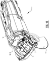
- a power tool 1 comprises a drive 2 and a first drive shaft 3 that is connected to said drive 2, and that has a first engagement 4 that is configured to engage a first type of accessory 5.
- the power tool 1 further comprises a second drive shaft 6 that is connected to said drive 2, and that has a second engagement 7 that is configured to engage a second type of accessory 8.
- the drive 2 is configured to drive the first drive shaft 3 and the second drive shaft 6 simultaneously.
- a user may couple a desired type of accessory 5, 8 that is configured to be used for a dedicated purpose.
- the power tool 1 is capable of being adapted for multiple purposes.
- the first drive shaft 3 is an oscillating drive shaft
- the first type of accessory 5 is a unit 9 that is configured to drive an oscillating tool 10.
- the second drive shaft 6 is a rotating drive shaft
- the second type of accessory 8 is a unit 11 that is configured to drive a rotating tool 17, e.g. a circular saw blade.
- a set of conical gears 13, 14 is used to drive the second drive shaft 6, i.e. the rotating drive shaft.
- the partially exploded Figure 6 shows an eccentric shaft 15 that engages an arm 16 that is fixed to the first drive shaft 3, i.e. the oscillating drive shaft.
- the power tool 1 further comprises a trigger 12 that is configured to switch said drive 2 on and off.
- the trigger 12 comprises a lock-on state or position ( Figure 11C ) in an engaged state of the first type of accessory 5, and a momentary state or position ( Figure 11B ) in an engaged state of the second type of accessory 8.
- the second type of accessory 8 is embodied in the Figures as a rotating tool 17 in the form of a circular saw blade.
- a circular saw blade is a tool with a relatively high risk associated with continued locked-on operation.
- the high risk circular saw blade must be actively held in an "on"-position by the user for activation thereof.
- the power tool 1 is capable of being adapted for multiple purposes, and also provides the comfort of a locked-on operation where appropriate on the one hand, whereas safety is safeguarded for other situations on the other hand.
- the unit 11 of the second type of accessory 8 accommodates a rotating tool 17 in the form of a circular saw blade.
- the unit 11 may further comprise a transmission 18 configured to drive said tool 17.
- the transmission 18 may comprise a gear ratio, such that the rotations per minute of said tool 17 are decreased or increased relative to the rotations per minute of the second drive shaft 6.
- the gear ratio may differ between different accessories 8.
- the first type of accessory 5 may also comprise a transmission with a gear ratio, allowing the oscillations per minute to be changed relative to the oscillations per minute of the first drive shaft 3. Again, the gear ratio may differ between different accessories 5.
- the second type of accessory 8 is configured to cover the first drive shaft 3 when it is engaged to the second drive shaft 6 (see Figures 8 and 9 ).
- the first type of accessory 5 may be configured to cover the second drive shaft 6 when it is engaged to the first drive shaft 3, and/or the second drive shaft 6 may be arranged in a countersunk manner, thereby shielding it from exposure.
- the trigger 12 is a sliding trigger
- the second type of accessory 8 activates a barrier 18 that is configured to prevent the sliding trigger 12 from locking in an on-position when said second type of accessory 8 is engaged to the second drive shaft 6 ( Figure 11B ).
- the barrier 18 is movable via said second type of accessory 8 and is pre-tensioned when said second type of accessory 8 is engaged to the second drive shaft 6.
- the pre-tensioning moves the barrier 18 relative to the trigger 12.
- the trigger 12 may now be moved again into a locked-on position ( Figure 11C ).
- the barrier 18 is a moveable element 19, such as a plate 19 that comprises a guide 20 in the form of a chamfer 20.
- Said guide 20 is configured to engage said trigger 12 ( Figures 8-10 and 11B ). If the trigger 12 would accidentally be in a locked-on position when the second type of accessory 8 is brought into engagement with the second drive shaft 6, the guide will force the trigger 12 to an off-position.
- a (not shown) activating member may enable a locked position of the trigger 12, so that - e.g. in an oscillating tool mode - the power tool 1 may be held in an on-state.
- the trigger 12 is connected to an arm 21 with a flange 22 that is configured to engage a micro switch 23.
- the micro switch 23 is connected to a controller 24, which also controls the drive 2.
- the second type of accessory 8 that is associated with the rotating second drive shaft 6 is a high risk tool 17 such as a circular saw blade.
- a grinder may only require a restart protection that guarantees that the power tool is always "off' when the power tool is connected to a power supply, such as a wall socket. This can be obtained using a momentary switch.
- a sander may however be lockable in an "on" position during use.
- Such low risk rotating tools may be provided as a (not shown) third type of accessory that is configured to engage the rotating second drive shaft 6, but will not evoke the momentary state.
- the third type of accessory will not activate a barrier that is configured to prevent the pressure trigger or any part of a trigger construction from locking in an on-state when said third type of accessory is engaged to the second drive shaft.
Landscapes
- Engineering & Computer Science (AREA)
- Mechanical Engineering (AREA)
- Sawing (AREA)
- Portable Power Tools In General (AREA)
Abstract
Description
- The present invention relates to a power tool, and to an assembly of a power tool and an accessory.
- Power tools are often designed for one specific type of use. Whereas professional users posses tools dedicated for each purpose, this is often not the case for do-it-yourself (DIY) workers. Many DIY-workers would prefer to have a power tool capable of being adapted for multiple purposes.
- The United States patent
US 4 818 916 is considered the closest prior art. The United Kingdompatent application GB 2 396 127 patent application DE 10 2812 221877 are acknowledged as further prior art. - One
disadvantage GB 2 396 127 US 4 818 916 have in common, is that also the drive shaft that is not in use remains exposed. A user may come into contact with such a driven drive shaft, and get hurt or even injured. - An object of the present invention is to provide a power tool, that is improved relative to the prior art and wherein at least one of the above stated problems is obviated.
- Said object is achieved with the power tool according to the present invention, comprising:
- a drive; and
- a first drive shaft that is connected to said drive, and having a first engagement that is configured to engage a first type of accessory;
- a second drive shaft that is connected to said drive, and having a second engagement that is configured to engage a second type of accessory; and
- wherein the drive is configured to drive the first drive shaft and the second drive shaft simultaneously.
- During use, the drive drives both the first drive shaft and the second drive shaft simultaneously. A user may couple a desired type of accessory that is configured to be used for a dedicated purpose. In this way, a power tool is provided that is capable of being adapted for multiple purposes.
- For example, the first drive shaft may be an oscillating drive shaft, and the first type of accessory may be a unit that is configured to drive an oscillating tool. The second drive shaft may be a rotating drive shaft, and the second type of accessory may be a unit that is configured to drive a rotating tool, e.g. a circular saw blade.
- According to a preferred embodiment, the first drive shaft and the second drive shaft extend in the same direction relative to the drive. This allows an accessory that is coupled to one of the first drive shaft or the second drive shaft to shield the other of the first or the second drive shaft.
- According to a preferred embodiment, said power tool further comprises a trigger that is configured to switch said drive on and off, wherein the trigger comprises:
- a lock-on state in an engaged state of the first type of accessory; and
- a momentary state in an engaged state of the second type of accessory.
- In the context of this invention, a momentary state is a state wherein the power tool is automatically turned "off' when the trigger is released. For certain types of power tools and certain types of use, there is a risk associated with a continued running after a release of the trigger. A trigger that comprises a lock-on state is to be interpreted as a trigger that can be locked in an "on"-state.
- Contrary to an oscillating multi tool saw blade, e.g. a circular saw is regarded as a tool with a relatively high risk associated with continued locked-on operation. By applying a momentary state when high risk tools are coupled to the power tool, it is guaranteed that the trigger does not stay 'on' by itself, but it must be actively hold in an on-position by a user.
- Further preferred embodiments are the subject of the dependent claims.
- In the following description preferred embodiments of the present invention are further elucidated with reference to the drawing, in which:
-
Figure 1 is a perspective view of a power tool according to the invention; -
Figure 2 is a detailed perspective view of the first drive shaft; -
Figure 3 is the power tool ofFigure 1 with a first type of accessory; -
Figure 4 is the power tool ofFigure 1 with a second type of accessory; -
Figure 5 in a perspective view of the drive shafts of the power tool ofFigure 1 ; -
Figure 6 is a partially exploded perspective view ofFigure 5 ; -
Figure 7 shows the tool ofFigure 5 before attachment of the second type of accessory; -
Figures 8 and9 show the tool ofFigure 5 after attachment of the second type of accessory; -
Figure 10 shows a tool conformFigure 9 ; and -
Figures 11A-11C show different states of the trigger. - A
power tool 1 according to an embodiment of the invention, comprises adrive 2 and afirst drive shaft 3 that is connected to saiddrive 2, and that has afirst engagement 4 that is configured to engage a first type ofaccessory 5. Thepower tool 1 further comprises asecond drive shaft 6 that is connected to saiddrive 2, and that has a second engagement 7 that is configured to engage a second type ofaccessory 8. Thedrive 2 is configured to drive thefirst drive shaft 3 and thesecond drive shaft 6 simultaneously. - A user may couple a desired type of
accessory power tool 1 is capable of being adapted for multiple purposes. - In the embodiment shown, the
first drive shaft 3 is an oscillating drive shaft, and the first type ofaccessory 5 is a unit 9 that is configured to drive an oscillatingtool 10. Thesecond drive shaft 6 is a rotating drive shaft, and the second type ofaccessory 8 is aunit 11 that is configured to drive a rotatingtool 17, e.g. a circular saw blade. As shown infigure 5 , a set ofconical gears second drive shaft 6, i.e. the rotating drive shaft. The partially explodedFigure 6 shows aneccentric shaft 15 that engages anarm 16 that is fixed to thefirst drive shaft 3, i.e. the oscillating drive shaft. - The
power tool 1 further comprises atrigger 12 that is configured to switch saiddrive 2 on and off. Thetrigger 12 comprises a lock-on state or position (Figure 11C ) in an engaged state of the first type ofaccessory 5, and a momentary state or position (Figure 11B ) in an engaged state of the second type ofaccessory 8. In this way, only the first type ofaccessory 5 may be locked in an "on"-state during use. The second type ofaccessory 8 is embodied in the Figures as arotating tool 17 in the form of a circular saw blade. Such a circular saw blade is a tool with a relatively high risk associated with continued locked-on operation. According to the invention, the high risk circular saw blade must be actively held in an "on"-position by the user for activation thereof. As a result, thepower tool 1 is capable of being adapted for multiple purposes, and also provides the comfort of a locked-on operation where appropriate on the one hand, whereas safety is safeguarded for other situations on the other hand. - In
Figure 7 , theunit 11 of the second type ofaccessory 8 accommodates a rotatingtool 17 in the form of a circular saw blade. Theunit 11 may further comprise atransmission 18 configured to drive saidtool 17. Thetransmission 18 may comprise a gear ratio, such that the rotations per minute of saidtool 17 are decreased or increased relative to the rotations per minute of thesecond drive shaft 6. The gear ratio may differ betweendifferent accessories 8. - Although not shown, the first type of
accessory 5 may also comprise a transmission with a gear ratio, allowing the oscillations per minute to be changed relative to the oscillations per minute of thefirst drive shaft 3. Again, the gear ratio may differ betweendifferent accessories 5. - The second type of
accessory 8 is configured to cover thefirst drive shaft 3 when it is engaged to the second drive shaft 6 (seeFigures 8 and9 ). Likewise, not shown, the first type ofaccessory 5 may be configured to cover thesecond drive shaft 6 when it is engaged to thefirst drive shaft 3, and/or thesecond drive shaft 6 may be arranged in a countersunk manner, thereby shielding it from exposure. - In the shown embodiment, the
trigger 12 is a sliding trigger, and the second type ofaccessory 8 activates abarrier 18 that is configured to prevent the slidingtrigger 12 from locking in an on-position when said second type ofaccessory 8 is engaged to the second drive shaft 6 (Figure 11B ). - The
barrier 18 is movable via said second type ofaccessory 8 and is pre-tensioned when said second type ofaccessory 8 is engaged to thesecond drive shaft 6. When the second type ofaccessory 8 is disengaged from thesecond drive shaft 6 and taken apart from thepower tool 1, the pre-tensioning moves thebarrier 18 relative to thetrigger 12. Thetrigger 12 may now be moved again into a locked-on position (Figure 11C ). - The
barrier 18 is a moveable element 19, such as a plate 19 that comprises aguide 20 in the form of achamfer 20. Saidguide 20 is configured to engage said trigger 12 (Figures 8-10 and11B ). If thetrigger 12 would accidentally be in a locked-on position when the second type ofaccessory 8 is brought into engagement with thesecond drive shaft 6, the guide will force thetrigger 12 to an off-position. Alternatively, instead of a barrier, a (not shown) activating member may enable a locked position of thetrigger 12, so that - e.g. in an oscillating tool mode - thepower tool 1 may be held in an on-state. - The
trigger 12 is connected to anarm 21 with aflange 22 that is configured to engage amicro switch 23. Themicro switch 23 is connected to acontroller 24, which also controls thedrive 2. - The above described embodiment is intended only to illustrate the invention and not to limit in any way the scope of the invention.
- In the example embodiment, the second type of
accessory 8 that is associated with the rotatingsecond drive shaft 6 is ahigh risk tool 17 such as a circular saw blade. However, not all types of rotating tools impose such a high risk. For example, a grinder may only require a restart protection that guarantees that the power tool is always "off' when the power tool is connected to a power supply, such as a wall socket. This can be obtained using a momentary switch. A sander may however be lockable in an "on" position during use. Such low risk rotating tools may be provided as a (not shown) third type of accessory that is configured to engage the rotatingsecond drive shaft 6, but will not evoke the momentary state. The third type of accessory will not activate a barrier that is configured to prevent the pressure trigger or any part of a trigger construction from locking in an on-state when said third type of accessory is engaged to the second drive shaft. - It should be understood that where features mentioned in the appended claims are followed by reference signs, such signs are included solely for the purpose of enhancing the intelligibility of the claims and are in no way limiting on the scope of the claims. The scope of the invention is defined solely by the following claims.
Claims (15)
- Power tool (1), comprising:- a drive (2); and- a first drive shaft (3) that is connected to said drive (2), and having a first engagement (4) that is configured to engage a first type of accessory (5);- a second drive shaft (6) that is connected to said drive (2), and having a second engagement (7) that is configured to engage a second type of accessory (8); and- wherein the drive (2) is configured to drive the first drive shaft (3) and the second drive shaft (6) simultaneously,
characterized in that- the first drive shaft (3) and the second drive shaft (6) extend in the same direction relative to the drive (2). - Power tool (1) according to claim 1, wherein the first drive shaft (3) is an oscillating drive shaft.
- Power tool (1) according to claim 1 or 2, wherein the first drive shaft (3) is parallel to the second drive shaft (6).
- Power tool (1) according to any of the foregoing claims, wherein the second drive shaft (6) is a rotating drive shaft.
- Power tool (1) according to any of the foregoing claims, further comprising a trigger (12) that is configured to switch said drive (2) on and off, wherein the trigger (12) comprises:- a lock-on state in an engaged state of the first type of accessory (5); and- a momentary state in an engaged state of the second type of accessory (8).
- Assembly of a power tool (1) according to any claims 1-5 and at least an accessory (5, 8) that is configured to drive a tool (10, 17).
- Assembly according to claim 6, wherein the accessory (5, 8) further comprises a transmission configured to drive said tool.
- Assembly according to claim 6 or 7, wherein the accessory (5, 8) is of the first type, and wherein the accessory of the first type (5) is a unit (9) that is configured to drive an oscillating tool (10).
- Assembly according to claim 2 and 8, wherein the oscillating tool (10) is directly coupleable to the oscillating drive shaft (3).
- Assembly according to claim 8 or 9, wherein the first type of accessory (5) is configured to cover the second drive shaft (6) when it is engaged to the first drive shaft (3).
- Assembly according to claim 6 or 7, wherein the accessory (8) is of the second type, and wherein the second type of accessory (8) is a unit (11) that is configured to drive a rotating tool (17).
- Assembly according to claim 11, wherein the second type of accessory (8) is configured to cover the first drive shaft (3) when it is engaged to the second drive shaft (6).
- Assembly according to claim 11 or 12 , wherein the second type of accessory (8) activates a barrier (19) that is configured to prevent the trigger (12) or any part of a trigger construction from locking in an on-state when said second type of accessory (8) is engaged to the second drive shaft (6).
- Assembly according to claim 13, wherein the barrier (19) is movable via said second type of accessory (8) and pre-tensioned when said second type of accessory (8) is engaged to the second drive shaft (6).
- Assembly according to claim 13 or 14, wherein the barrier (19) is a moveable element that comprises a guide that is configured to engage the trigger or the trigger construction to activate the momentary state.
Applications Claiming Priority (2)
| Application Number | Priority Date | Filing Date | Title |
|---|---|---|---|
| NL2018778A NL2018778B1 (en) | 2017-04-25 | 2017-04-25 | Power tool |
| EP18169042.1A EP3401061B1 (en) | 2017-04-25 | 2018-04-24 | Power tool, and assembly of such a power tool and an accessory |
Related Parent Applications (2)
| Application Number | Title | Priority Date | Filing Date |
|---|---|---|---|
| EP18169042.1A Division EP3401061B1 (en) | 2017-04-25 | 2018-04-24 | Power tool, and assembly of such a power tool and an accessory |
| EP18169042.1A Division-Into EP3401061B1 (en) | 2017-04-25 | 2018-04-24 | Power tool, and assembly of such a power tool and an accessory |
Publications (2)
| Publication Number | Publication Date |
|---|---|
| EP3797930A1 true EP3797930A1 (en) | 2021-03-31 |
| EP3797930B1 EP3797930B1 (en) | 2023-03-29 |
Family
ID=59521605
Family Applications (2)
| Application Number | Title | Priority Date | Filing Date |
|---|---|---|---|
| EP18169042.1A Active EP3401061B1 (en) | 2017-04-25 | 2018-04-24 | Power tool, and assembly of such a power tool and an accessory |
| EP20207876.2A Active EP3797930B1 (en) | 2017-04-25 | 2018-04-24 | Power tool |
Family Applications Before (1)
| Application Number | Title | Priority Date | Filing Date |
|---|---|---|---|
| EP18169042.1A Active EP3401061B1 (en) | 2017-04-25 | 2018-04-24 | Power tool, and assembly of such a power tool and an accessory |
Country Status (2)
| Country | Link |
|---|---|
| EP (2) | EP3401061B1 (en) |
| NL (1) | NL2018778B1 (en) |
Families Citing this family (1)
| Publication number | Priority date | Publication date | Assignee | Title |
|---|---|---|---|---|
| US12338881B2 (en) * | 2020-07-10 | 2025-06-24 | Robert Bosch Tool Corporation | Multi-motion appliance |
Citations (6)
| Publication number | Priority date | Publication date | Assignee | Title |
|---|---|---|---|---|
| US4810916A (en) * | 1987-12-16 | 1989-03-07 | Mcbride Scott | Rotary power tool having dual outputs |
| US4818916A (en) | 1987-03-06 | 1989-04-04 | The Perkin-Elmer Corporation | Power system for inductively coupled plasma torch |
| GB2396127A (en) | 2002-12-14 | 2004-06-16 | Black & Decker Inc | Dual output power tool |
| DE102012221877A1 (en) | 2011-12-02 | 2013-06-06 | GM Global Technology Operations LLC (n.d. Ges. d. Staates Delaware) | FOR REGULATING THE FLOW OF A FLUID FROM A TRANSMISSION TO A COOLER TRAINED VALVE |
| EP2639015A2 (en) * | 2012-03-13 | 2013-09-18 | Black & Decker Inc. | Power Tool |
| DE102012221077A1 (en) * | 2012-11-19 | 2014-05-22 | Robert Bosch Gmbh | Cultivation module i.e. dust suction module, for e.g. drilling hammer, has translation device rotatable arranged with driven shaft, and push pull cable and belt and/or chain unit arranged at input side to output side with transmission ratio |
Family Cites Families (1)
| Publication number | Priority date | Publication date | Assignee | Title |
|---|---|---|---|---|
| AUPM464594A0 (en) * | 1994-03-23 | 1994-04-21 | Black & Decker Incorporated | Drill configuration |
-
2017
- 2017-04-25 NL NL2018778A patent/NL2018778B1/en active
-
2018
- 2018-04-24 EP EP18169042.1A patent/EP3401061B1/en active Active
- 2018-04-24 EP EP20207876.2A patent/EP3797930B1/en active Active
Patent Citations (6)
| Publication number | Priority date | Publication date | Assignee | Title |
|---|---|---|---|---|
| US4818916A (en) | 1987-03-06 | 1989-04-04 | The Perkin-Elmer Corporation | Power system for inductively coupled plasma torch |
| US4810916A (en) * | 1987-12-16 | 1989-03-07 | Mcbride Scott | Rotary power tool having dual outputs |
| GB2396127A (en) | 2002-12-14 | 2004-06-16 | Black & Decker Inc | Dual output power tool |
| DE102012221877A1 (en) | 2011-12-02 | 2013-06-06 | GM Global Technology Operations LLC (n.d. Ges. d. Staates Delaware) | FOR REGULATING THE FLOW OF A FLUID FROM A TRANSMISSION TO A COOLER TRAINED VALVE |
| EP2639015A2 (en) * | 2012-03-13 | 2013-09-18 | Black & Decker Inc. | Power Tool |
| DE102012221077A1 (en) * | 2012-11-19 | 2014-05-22 | Robert Bosch Gmbh | Cultivation module i.e. dust suction module, for e.g. drilling hammer, has translation device rotatable arranged with driven shaft, and push pull cable and belt and/or chain unit arranged at input side to output side with transmission ratio |
Also Published As
| Publication number | Publication date |
|---|---|
| EP3401061A1 (en) | 2018-11-14 |
| EP3401061B1 (en) | 2020-12-30 |
| NL2018778B1 (en) | 2018-11-05 |
| EP3797930B1 (en) | 2023-03-29 |
Similar Documents
| Publication | Publication Date | Title |
|---|---|---|
| US9114499B2 (en) | Working tool | |
| US7814818B2 (en) | Modular table saw guarding system riving knife release mechanisms | |
| EP3192620B1 (en) | Miter saw | |
| US6293859B1 (en) | Electric power tool with rotatable handle | |
| EP3081335B1 (en) | Guard assembly for a power tool | |
| US10014128B2 (en) | Portable power tool with trigger switch, trigger release and lock-on mechanism combination | |
| US4280026A (en) | Actuator mechanism for a portable, hand-held tool | |
| TW200420375A (en) | Multiple position switch handle with locking mechanism | |
| JP2007111853A (en) | Protective cover device for tool device | |
| US20180326554A1 (en) | Hand-Held Power Tool Having at Least One Machine-Side Contact Element | |
| US7526867B2 (en) | Tool with clamping apparatus and an improved scrolling mechanism | |
| WO2008061198A3 (en) | Power tool | |
| GB2436438A (en) | Mounting a hood on a portable power tool | |
| WO2018043330A1 (en) | Working machine | |
| EP3045277A1 (en) | Miter saw with miter angle lock | |
| US10456945B2 (en) | Tool for manually operating oscillating motorized tool accessory | |
| EP3251791B1 (en) | Reversible lever for a guard assembly for a power tool | |
| EP3401061B1 (en) | Power tool, and assembly of such a power tool and an accessory | |
| EP2101945B1 (en) | Electrical machine tool, such as an angle grinder, with spindle blocking device | |
| EP3150333B1 (en) | Power tool with improved braking device | |
| EP3530866A1 (en) | Fastening device for releasable fastening of a screen to a leaf | |
| CN210705394U (en) | Cutting mechanism of ceramic tile cutting machine and ceramic tile cutting machine | |
| JP5287068B2 (en) | Electric tool | |
| AU2017219070B2 (en) | Drive-in device | |
| KR101869334B1 (en) | Multi Tool with Mechanism for Preventing Reverse Rotation |
Legal Events
| Date | Code | Title | Description |
|---|---|---|---|
| PUAI | Public reference made under article 153(3) epc to a published international application that has entered the european phase |
Free format text: ORIGINAL CODE: 0009012 |
|
| STAA | Information on the status of an ep patent application or granted ep patent |
Free format text: STATUS: THE APPLICATION HAS BEEN PUBLISHED |
|
| AC | Divisional application: reference to earlier application |
Ref document number: 3401061 Country of ref document: EP Kind code of ref document: P |
|
| AK | Designated contracting states |
Kind code of ref document: A1 Designated state(s): AL AT BE BG CH CY CZ DE DK EE ES FI FR GB GR HR HU IE IS IT LI LT LU LV MC MK MT NL NO PL PT RO RS SE SI SK SM TR |
|
| STAA | Information on the status of an ep patent application or granted ep patent |
Free format text: STATUS: REQUEST FOR EXAMINATION WAS MADE |
|
| RIN1 | Information on inventor provided before grant (corrected) |
Inventor name: QUIRIJNEN, ANTONIUS JOHANNES JACOBUS Inventor name: VAN RIJCKEVORSEL, PETRUS PATRICK LEONARDUS |
|
| 17P | Request for examination filed |
Effective date: 20210910 |
|
| RBV | Designated contracting states (corrected) |
Designated state(s): AL AT BE BG CH CY CZ DE DK EE ES FI FR GB GR HR HU IE IS IT LI LT LU LV MC MK MT NL NO PL PT RO RS SE SI SK SM TR |
|
| RAP1 | Party data changed (applicant data changed or rights of an application transferred) |
Owner name: NANJING CHERVON INDUSTRY CO., LTD. |
|
| STAA | Information on the status of an ep patent application or granted ep patent |
Free format text: STATUS: EXAMINATION IS IN PROGRESS |
|
| 17Q | First examination report despatched |
Effective date: 20220121 |
|
| GRAP | Despatch of communication of intention to grant a patent |
Free format text: ORIGINAL CODE: EPIDOSNIGR1 |
|
| STAA | Information on the status of an ep patent application or granted ep patent |
Free format text: STATUS: GRANT OF PATENT IS INTENDED |
|
| INTG | Intention to grant announced |
Effective date: 20230103 |
|
| GRAS | Grant fee paid |
Free format text: ORIGINAL CODE: EPIDOSNIGR3 |
|
| GRAA | (expected) grant |
Free format text: ORIGINAL CODE: 0009210 |
|
| STAA | Information on the status of an ep patent application or granted ep patent |
Free format text: STATUS: THE PATENT HAS BEEN GRANTED |
|
| AC | Divisional application: reference to earlier application |
Ref document number: 3401061 Country of ref document: EP Kind code of ref document: P |
|
| AK | Designated contracting states |
Kind code of ref document: B1 Designated state(s): AL AT BE BG CH CY CZ DE DK EE ES FI FR GB GR HR HU IE IS IT LI LT LU LV MC MK MT NL NO PL PT RO RS SE SI SK SM TR |
|
| REG | Reference to a national code |
Ref country code: CH Ref legal event code: EP |
|
| REG | Reference to a national code |
Ref country code: DE Ref legal event code: R096 Ref document number: 602018047936 Country of ref document: DE |
|
| REG | Reference to a national code |
Ref country code: AT Ref legal event code: REF Ref document number: 1556349 Country of ref document: AT Kind code of ref document: T Effective date: 20230415 |
|
| REG | Reference to a national code |
Ref country code: IE Ref legal event code: FG4D |
|
| REG | Reference to a national code |
Ref country code: LT Ref legal event code: MG9D |
|
| PG25 | Lapsed in a contracting state [announced via postgrant information from national office to epo] |
Ref country code: RS Free format text: LAPSE BECAUSE OF FAILURE TO SUBMIT A TRANSLATION OF THE DESCRIPTION OR TO PAY THE FEE WITHIN THE PRESCRIBED TIME-LIMIT Effective date: 20230329 Ref country code: NO Free format text: LAPSE BECAUSE OF FAILURE TO SUBMIT A TRANSLATION OF THE DESCRIPTION OR TO PAY THE FEE WITHIN THE PRESCRIBED TIME-LIMIT Effective date: 20230629 Ref country code: LV Free format text: LAPSE BECAUSE OF FAILURE TO SUBMIT A TRANSLATION OF THE DESCRIPTION OR TO PAY THE FEE WITHIN THE PRESCRIBED TIME-LIMIT Effective date: 20230329 Ref country code: LT Free format text: LAPSE BECAUSE OF FAILURE TO SUBMIT A TRANSLATION OF THE DESCRIPTION OR TO PAY THE FEE WITHIN THE PRESCRIBED TIME-LIMIT Effective date: 20230329 Ref country code: HR Free format text: LAPSE BECAUSE OF FAILURE TO SUBMIT A TRANSLATION OF THE DESCRIPTION OR TO PAY THE FEE WITHIN THE PRESCRIBED TIME-LIMIT Effective date: 20230329 |
|
| REG | Reference to a national code |
Ref country code: NL Ref legal event code: MP Effective date: 20230329 |
|
| REG | Reference to a national code |
Ref country code: AT Ref legal event code: MK05 Ref document number: 1556349 Country of ref document: AT Kind code of ref document: T Effective date: 20230329 |
|
| PG25 | Lapsed in a contracting state [announced via postgrant information from national office to epo] |
Ref country code: SE Free format text: LAPSE BECAUSE OF FAILURE TO SUBMIT A TRANSLATION OF THE DESCRIPTION OR TO PAY THE FEE WITHIN THE PRESCRIBED TIME-LIMIT Effective date: 20230329 Ref country code: NL Free format text: LAPSE BECAUSE OF FAILURE TO SUBMIT A TRANSLATION OF THE DESCRIPTION OR TO PAY THE FEE WITHIN THE PRESCRIBED TIME-LIMIT Effective date: 20230329 Ref country code: GR Free format text: LAPSE BECAUSE OF FAILURE TO SUBMIT A TRANSLATION OF THE DESCRIPTION OR TO PAY THE FEE WITHIN THE PRESCRIBED TIME-LIMIT Effective date: 20230630 Ref country code: FI Free format text: LAPSE BECAUSE OF FAILURE TO SUBMIT A TRANSLATION OF THE DESCRIPTION OR TO PAY THE FEE WITHIN THE PRESCRIBED TIME-LIMIT Effective date: 20230329 |
|
| PG25 | Lapsed in a contracting state [announced via postgrant information from national office to epo] |
Ref country code: SM Free format text: LAPSE BECAUSE OF FAILURE TO SUBMIT A TRANSLATION OF THE DESCRIPTION OR TO PAY THE FEE WITHIN THE PRESCRIBED TIME-LIMIT Effective date: 20230329 Ref country code: RO Free format text: LAPSE BECAUSE OF FAILURE TO SUBMIT A TRANSLATION OF THE DESCRIPTION OR TO PAY THE FEE WITHIN THE PRESCRIBED TIME-LIMIT Effective date: 20230329 Ref country code: PT Free format text: LAPSE BECAUSE OF FAILURE TO SUBMIT A TRANSLATION OF THE DESCRIPTION OR TO PAY THE FEE WITHIN THE PRESCRIBED TIME-LIMIT Effective date: 20230731 Ref country code: ES Free format text: LAPSE BECAUSE OF FAILURE TO SUBMIT A TRANSLATION OF THE DESCRIPTION OR TO PAY THE FEE WITHIN THE PRESCRIBED TIME-LIMIT Effective date: 20230329 Ref country code: EE Free format text: LAPSE BECAUSE OF FAILURE TO SUBMIT A TRANSLATION OF THE DESCRIPTION OR TO PAY THE FEE WITHIN THE PRESCRIBED TIME-LIMIT Effective date: 20230329 Ref country code: AT Free format text: LAPSE BECAUSE OF FAILURE TO SUBMIT A TRANSLATION OF THE DESCRIPTION OR TO PAY THE FEE WITHIN THE PRESCRIBED TIME-LIMIT Effective date: 20230329 |
|
| PG25 | Lapsed in a contracting state [announced via postgrant information from national office to epo] |
Ref country code: SK Free format text: LAPSE BECAUSE OF FAILURE TO SUBMIT A TRANSLATION OF THE DESCRIPTION OR TO PAY THE FEE WITHIN THE PRESCRIBED TIME-LIMIT Effective date: 20230329 Ref country code: PL Free format text: LAPSE BECAUSE OF FAILURE TO SUBMIT A TRANSLATION OF THE DESCRIPTION OR TO PAY THE FEE WITHIN THE PRESCRIBED TIME-LIMIT Effective date: 20230329 Ref country code: IS Free format text: LAPSE BECAUSE OF FAILURE TO SUBMIT A TRANSLATION OF THE DESCRIPTION OR TO PAY THE FEE WITHIN THE PRESCRIBED TIME-LIMIT Effective date: 20230729 |
|
| REG | Reference to a national code |
Ref country code: CH Ref legal event code: PL |
|
| PG25 | Lapsed in a contracting state [announced via postgrant information from national office to epo] |
Ref country code: LU Free format text: LAPSE BECAUSE OF NON-PAYMENT OF DUE FEES Effective date: 20230424 |
|
| REG | Reference to a national code |
Ref country code: DE Ref legal event code: R097 Ref document number: 602018047936 Country of ref document: DE |
|
| REG | Reference to a national code |
Ref country code: BE Ref legal event code: MM Effective date: 20230430 |
|
| PG25 | Lapsed in a contracting state [announced via postgrant information from national office to epo] |
Ref country code: MC Free format text: LAPSE BECAUSE OF FAILURE TO SUBMIT A TRANSLATION OF THE DESCRIPTION OR TO PAY THE FEE WITHIN THE PRESCRIBED TIME-LIMIT Effective date: 20230329 |
|
| PG25 | Lapsed in a contracting state [announced via postgrant information from national office to epo] |
Ref country code: MC Free format text: LAPSE BECAUSE OF FAILURE TO SUBMIT A TRANSLATION OF THE DESCRIPTION OR TO PAY THE FEE WITHIN THE PRESCRIBED TIME-LIMIT Effective date: 20230329 Ref country code: LI Free format text: LAPSE BECAUSE OF NON-PAYMENT OF DUE FEES Effective date: 20230430 Ref country code: DK Free format text: LAPSE BECAUSE OF FAILURE TO SUBMIT A TRANSLATION OF THE DESCRIPTION OR TO PAY THE FEE WITHIN THE PRESCRIBED TIME-LIMIT Effective date: 20230329 Ref country code: CZ Free format text: LAPSE BECAUSE OF FAILURE TO SUBMIT A TRANSLATION OF THE DESCRIPTION OR TO PAY THE FEE WITHIN THE PRESCRIBED TIME-LIMIT Effective date: 20230329 Ref country code: CH Free format text: LAPSE BECAUSE OF NON-PAYMENT OF DUE FEES Effective date: 20230430 |
|
| PLBE | No opposition filed within time limit |
Free format text: ORIGINAL CODE: 0009261 |
|
| STAA | Information on the status of an ep patent application or granted ep patent |
Free format text: STATUS: NO OPPOSITION FILED WITHIN TIME LIMIT |
|
| REG | Reference to a national code |
Ref country code: IE Ref legal event code: MM4A |
|
| PG25 | Lapsed in a contracting state [announced via postgrant information from national office to epo] |
Ref country code: BE Free format text: LAPSE BECAUSE OF NON-PAYMENT OF DUE FEES Effective date: 20230430 |
|
| 26N | No opposition filed |
Effective date: 20240103 |
|
| PG25 | Lapsed in a contracting state [announced via postgrant information from national office to epo] |
Ref country code: IE Free format text: LAPSE BECAUSE OF NON-PAYMENT OF DUE FEES Effective date: 20230424 |
|
| PG25 | Lapsed in a contracting state [announced via postgrant information from national office to epo] |
Ref country code: IE Free format text: LAPSE BECAUSE OF NON-PAYMENT OF DUE FEES Effective date: 20230424 |
|
| PG25 | Lapsed in a contracting state [announced via postgrant information from national office to epo] |
Ref country code: SI Free format text: LAPSE BECAUSE OF FAILURE TO SUBMIT A TRANSLATION OF THE DESCRIPTION OR TO PAY THE FEE WITHIN THE PRESCRIBED TIME-LIMIT Effective date: 20230329 |
|
| PG25 | Lapsed in a contracting state [announced via postgrant information from national office to epo] |
Ref country code: SI Free format text: LAPSE BECAUSE OF FAILURE TO SUBMIT A TRANSLATION OF THE DESCRIPTION OR TO PAY THE FEE WITHIN THE PRESCRIBED TIME-LIMIT Effective date: 20230329 Ref country code: IT Free format text: LAPSE BECAUSE OF FAILURE TO SUBMIT A TRANSLATION OF THE DESCRIPTION OR TO PAY THE FEE WITHIN THE PRESCRIBED TIME-LIMIT Effective date: 20230329 |
|
| PG25 | Lapsed in a contracting state [announced via postgrant information from national office to epo] |
Ref country code: BG Free format text: LAPSE BECAUSE OF FAILURE TO SUBMIT A TRANSLATION OF THE DESCRIPTION OR TO PAY THE FEE WITHIN THE PRESCRIBED TIME-LIMIT Effective date: 20230329 |
|
| PG25 | Lapsed in a contracting state [announced via postgrant information from national office to epo] |
Ref country code: BG Free format text: LAPSE BECAUSE OF FAILURE TO SUBMIT A TRANSLATION OF THE DESCRIPTION OR TO PAY THE FEE WITHIN THE PRESCRIBED TIME-LIMIT Effective date: 20230329 |
|
| PGFP | Annual fee paid to national office [announced via postgrant information from national office to epo] |
Ref country code: DE Payment date: 20250225 Year of fee payment: 8 |
|
| PG25 | Lapsed in a contracting state [announced via postgrant information from national office to epo] |
Ref country code: CY Free format text: LAPSE BECAUSE OF FAILURE TO SUBMIT A TRANSLATION OF THE DESCRIPTION OR TO PAY THE FEE WITHIN THE PRESCRIBED TIME-LIMIT; INVALID AB INITIO Effective date: 20180424 |
|
| PG25 | Lapsed in a contracting state [announced via postgrant information from national office to epo] |
Ref country code: HU Free format text: LAPSE BECAUSE OF FAILURE TO SUBMIT A TRANSLATION OF THE DESCRIPTION OR TO PAY THE FEE WITHIN THE PRESCRIBED TIME-LIMIT; INVALID AB INITIO Effective date: 20180424 |
|
| PG25 | Lapsed in a contracting state [announced via postgrant information from national office to epo] |
Ref country code: TR Free format text: LAPSE BECAUSE OF FAILURE TO SUBMIT A TRANSLATION OF THE DESCRIPTION OR TO PAY THE FEE WITHIN THE PRESCRIBED TIME-LIMIT Effective date: 20230329 |
|
| PGFP | Annual fee paid to national office [announced via postgrant information from national office to epo] |
Ref country code: GB Payment date: 20260313 Year of fee payment: 9 |
|
| PGFP | Annual fee paid to national office [announced via postgrant information from national office to epo] |
Ref country code: FR Payment date: 20260309 Year of fee payment: 9 |