EP3797872A1 - Centrifugal separator and a method to control of the same - Google Patents
Centrifugal separator and a method to control of the same Download PDFInfo
- Publication number
- EP3797872A1 EP3797872A1 EP19199430.0A EP19199430A EP3797872A1 EP 3797872 A1 EP3797872 A1 EP 3797872A1 EP 19199430 A EP19199430 A EP 19199430A EP 3797872 A1 EP3797872 A1 EP 3797872A1
- Authority
- EP
- European Patent Office
- Prior art keywords
- outlet
- centrifugal separator
- hermetic
- flow rate
- flow
- Prior art date
- Legal status (The legal status is an assumption and is not a legal conclusion. Google has not performed a legal analysis and makes no representation as to the accuracy of the status listed.)
- Granted
Links
Images



Classifications
-
- B—PERFORMING OPERATIONS; TRANSPORTING
- B04—CENTRIFUGAL APPARATUS OR MACHINES FOR CARRYING-OUT PHYSICAL OR CHEMICAL PROCESSES
- B04B—CENTRIFUGES
- B04B5/00—Other centrifuges
- B04B5/04—Radial chamber apparatus for separating predominantly liquid mixtures, e.g. butyrometers
-
- B—PERFORMING OPERATIONS; TRANSPORTING
- B04—CENTRIFUGAL APPARATUS OR MACHINES FOR CARRYING-OUT PHYSICAL OR CHEMICAL PROCESSES
- B04B—CENTRIFUGES
- B04B5/00—Other centrifuges
- B04B5/04—Radial chamber apparatus for separating predominantly liquid mixtures, e.g. butyrometers
- B04B5/0442—Radial chamber apparatus for separating predominantly liquid mixtures, e.g. butyrometers with means for adding or withdrawing liquid substances during the centrifugation, e.g. continuous centrifugation
-
- B—PERFORMING OPERATIONS; TRANSPORTING
- B04—CENTRIFUGAL APPARATUS OR MACHINES FOR CARRYING-OUT PHYSICAL OR CHEMICAL PROCESSES
- B04B—CENTRIFUGES
- B04B1/00—Centrifuges with rotary bowls provided with solid jackets for separating predominantly liquid mixtures with or without solid particles
- B04B1/04—Centrifuges with rotary bowls provided with solid jackets for separating predominantly liquid mixtures with or without solid particles with inserted separating walls
- B04B1/08—Centrifuges with rotary bowls provided with solid jackets for separating predominantly liquid mixtures with or without solid particles with inserted separating walls of conical shape
-
- B—PERFORMING OPERATIONS; TRANSPORTING
- B04—CENTRIFUGAL APPARATUS OR MACHINES FOR CARRYING-OUT PHYSICAL OR CHEMICAL PROCESSES
- B04B—CENTRIFUGES
- B04B11/00—Feeding, charging, or discharging bowls
- B04B11/02—Continuous feeding or discharging; Control arrangements therefor
-
- B—PERFORMING OPERATIONS; TRANSPORTING
- B04—CENTRIFUGAL APPARATUS OR MACHINES FOR CARRYING-OUT PHYSICAL OR CHEMICAL PROCESSES
- B04B—CENTRIFUGES
- B04B13/00—Control arrangements specially designed for centrifuges; Program control of centrifuges
-
- B—PERFORMING OPERATIONS; TRANSPORTING
- B04—CENTRIFUGAL APPARATUS OR MACHINES FOR CARRYING-OUT PHYSICAL OR CHEMICAL PROCESSES
- B04B—CENTRIFUGES
- B04B5/00—Other centrifuges
- B04B5/04—Radial chamber apparatus for separating predominantly liquid mixtures, e.g. butyrometers
- B04B5/0442—Radial chamber apparatus for separating predominantly liquid mixtures, e.g. butyrometers with means for adding or withdrawing liquid substances during the centrifugation, e.g. continuous centrifugation
- B04B2005/0464—Radial chamber apparatus for separating predominantly liquid mixtures, e.g. butyrometers with means for adding or withdrawing liquid substances during the centrifugation, e.g. continuous centrifugation with hollow or massive core in centrifuge bowl
Definitions
- the present invention relates to a centrifugal separator for separation of a liquid mixture into a heavy phase and a light phase and a method to control such a centrifugal separator.
- a centrifugal separator for clarification of beer having a sludge space where the separated heavy phase comprising yeast is collected
- the yeast is ejected through discharges by intermittently opening outlets in the periphery of the separator bowl while the clarified beer is leaving the centrifugal separator through a hermetic outlet or a paring disc outlet.
- the yeast concentration in the feed to the separator is far from constant it is difficult to optimize the operation to obtain best possible result.
- the throughput capacity of the separator is then limited by the discharge frequency needed.
- the turbidity of the clarified beer is often used as input signal for triggering discharges, by using PLC-control.
- Yeast cells leaving the centrifugal separator by the second outlet have a high probability to survive the centrifugation and may be used for the next brewing batch, while much of the yeast cells that are ejected at the intermittent discharges in the third outlet are dead and are not usable in further fermentation.
- the manifold of concentrate pipes is an unstable configuration. If one pipe gets a disturbance in yeast concentration, for instance a slightly higher yeast concentration, the concentrate of this pipe becomes denser and more viscous. This leads to a flow reduction in that pipe relative to the other pipes of the manifold. The flow reduction leads to a further increase in yeast concentration in the pipe, and as a consequence, the disturbance is self-amplifying and growing in amplitude until the concentrate pipe clogs.
- the object of the present invention is to reduce the risk of clogging in such conduits transporting heavy phase, such as yeast concentrate, from a sludge space to an outlet.
- said centrifugal separator has a centrifugal separator bowl rotatable around an axis and encasing a separation space, and a sludge space radially outward of said separation space, comprising a hermetic inlet for feeding a liquid mixture to said separation space; a first hermetic outlet for a separated clarified light phase; a second hermetic outlet for a separated heavy phase; and a plurality of outlet conduits 5 extending from an outer position in said sludge space 12 to said second hermetic outlet; wherein each of the outlet conduits has a flow restriction in the form of a nozzle or vortex diode.
- said outlet conduits are at least partly shaped as pipes.
- the cross-section of said outlet conduits is circular.
- the flow restrictions are in the form of exchangeable pieces.
- the flow restrictions are formed in a ring piece having one vortex diode or nozzle for each outlet conduit.
- the second hermetic outlet for heavy phase has a mechanical seal of larger diameter than a mechanical seal on the first hermetic outlet for light phase.
- the radius of the heavy phase outlet mechanical seal, and the outer radius of the disc stack is larger than 20%.
- the centrifugal separator bowl has a third outlet for intermittent discharge at its periphery.
- a control valve is arranged in the second hermetic outlet.
- a control valve is arranged in the first hermetic outlet.
- At least one measuring device is arranged in the second hermetic outlet measuring density and flow rate, which device is connected to a programmable logic controller (PLC) and adapted to send data representing density and flow rate respectively, which PLC is adapted to process the data to determine if the combination of values of flow rate and density lies within a predetermined scope of values corresponding to a stable flow through said outlet conduits or not, wherein an actuator is adapted to manipulate one or both of said control valves in response to a correction signal sent by said PLC if said combination of values of flow rate and density does not lie within said predetermined scope.
- PLC programmable logic controller
- the above object is realized in a second aspect, by a method to control a centrifugal separator, in order to provide a stable flow through said outlet conduits, combinations of values of flow rate and density of the heavy phase is established where a stable flow through said outlet conduits are maintained, the flow rate and density of the heavy phase in said second hermetic outlet are measured continuously or intermittently and compared to said combinations of values by a PLC, the flow rate in said second hermetic outlet is regulated so a stable flow is maintained.
- the PLC is set to follow a curve corresponding to combinations of flow rate and density in said second hermetic outlet, with a margin to a stability limit curve, under which stability limit curve the conduits may clog.
- Fig. 7 shows a centrifugal separator 100 for separating a fluid mixture into a light phase of clarified liquid and a heavy phase of sludge/sediment.
- the centrifugal separator 100 comprises a frame 102, a hollow spindle 11, which is rotatably supported by the frame 102 in a bearing arrangement 103, and a centrifugal separator bowl 18 having a rotor casing 105.
- the rotor casing 105 is fixedly adjoined to the axially upper end of the spindle 11 enabling a drive arrangement 104 to rotate the centrifugal separator bowl 18 together with the spindle 11 around an axis (X) of rotation.
- the drive arrangement 104 may be a direct drive motor where the rotor of the motor is fixed to or is a part of spindle 11 or it may involve a transmission transmitting rotational movement from a separate motor via a belt-drive or gear-drive.
- the rotor casing 105 encloses a separation space 106 in which a stack 13 of separation discs is arranged in order to achieve effective separation of the fluid mixture that is processed.
- a distributor 19a is arranged coaxially to the spindle 11.
- the distributor 19a is functioning as a nave on which said stack 13 of separation discs is fitted centrally and coaxially with the rotor casing 105.
- the separation discs of the stack 13 have a frustoconical shape and are examples of surface-enlarging inserts. Only a few separation discs are shown but a stack 13 may for example contain above 100 separation discs, such as above 200 separation discs.
- a sludge space 12 In the centrifugal separator bowl 18 radially outside of said stack 13 of separation discs is a sludge space 12 for receiving the heavier content of the fluid mixture.
- the rotor casing 105 has a mechanically hermetically sealed liquid outlet 1 for discharge of a separated liquid light phase, and a heavy phase outlet 2 for discharge of a phase of higher density than the separated liquid light phase. There is a number of outlet conduits 5 in the form of channels for transporting separated heavy phase from the separation space 106.
- the channels may be in the form of separate pipes, or may be channels which form part of the bowl wall.
- the outlet conduits 5 extend from a radially outer position of the separation space 106 to the heavy phase outlet 2. As can be seen in better detail in Fig. 1 , the outlet conduits 5 have a conduit inlet 5a arranged at the radially outer position and a conduit outlet 5b arranged at a radially inner position. Further the outlet conduits 5 are arranged with an upward tilt relative the radial plane from the conduit inlet 5a to the conduit outlet 5b.
- Each of the outlet conduits has a flow restriction in the form of a vortex diode 7.
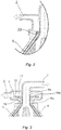
- the flow restriction can also be simple nozzles 20 like in Fig. 2 causing a pressure drop.
- Flow restrictions in form of vortex diodes are preferable as these show pressure drop reduction as viscosity increase, resulting in improved stability of the manifold consisting of a plurality of outlet conduits 5.
- a simple a nozzle 20 has a viscosity independent pressure drop and does not work as well. Increasing pressure drop by just reducing cross section of the conduits 5 does not work as this gives increased pressure drop with increased concentration.
- outlet conduits 5 continues as separated channels out to the vicinity of the outer diameter of an impeller 15 comprising a pump wheel 15a rotating with said centrifugal separator bowl 18, where the flow restrictions 7 in the form of vortex diodes 7 (or nozzles 20) are positioned at the end of the conduits 5 at the vicinity of outer diameter of the pump wheel 15a.
- the vortex nozzles are thus placed in the impeller 15 close to the periphery of the impeller to reduce the risk of cavitation or degassing, especially in beer separation.
- the pressure in the section with the smallest radius can thus be increased while keeping the stabilizing feature of the nozzles. For this to work it is necessary that the flow paths from all concentrate tubes are kept separate all the way up to the nozzles 20.
- Commonly used separator outlet pump wheels are designed as standard centrifugal pump wheels having curved vanes.
- a pump wheel according to the invention differs from this as the outlet conduits 5 continues as separate closed conduits all the way to the flow restriction at the outer diameter of the pump wheel.
- This flow restriction can be in the form of a vortex diode 7 or just a plain nozzle 20.
- the part of the outlet conduits 5 extending in the pump wheel can be in the form of curved channels and/or as radial channels.
- Fig. 1 the outlet conduits 5 are executed as pipes stretching out in the sludge space 12 to a diameter larger than the disc stack diameter.
- the heavy phase flowing in the outlet conduits 5 is yeast concentrate.
- the spindle 11 is hollow and has in its center parallell with the axis of rotation an inlet channel 4 for feeding the fluid mixture to be separated into said separator bowl 18.
- Said inlet channel 4 leads the fluid mixture to the distributor channels 19 which transport the fluid mixture from the center of the rotor out to the distributing holes 14 of the stack of conical separator discs 13.
- Clarified liquid is taken out from the center of the disc stack and leaves the separator by the liquid outlet 1 for discharge of a separated liquid light phase.
- the heavier concentrate and sediment goes to the sludge space 12. Concentrate and sediment can leave the sludge space 12 either by the second outlet 2 or by discharge ports for intermittent discharge 3.
- the opening and closing of the discharge ports 3 is managed by a hydraulically operated sliding bowl bottom 10.
- the first and second outlet 1, 2 have mechanical seals 6a, 6b. As this is an airtight design, it is also often called hermetic seals.
- the inlet channel 4 also has a mechanical seal sealing between a stationary part of said inlet channel and a lower end of the hollow spindle 11, thus preventing communication between the inlet channel and the surroundings. This mechanical seal is not shown in this figure.
- the heavy phase outlet On a larger diameter of the centrifugal separator bowl than the light phase outlet. It is even preferable to have a heavy phase outlet mechanical seal with a diameter larger than normally, as when the diameter is set from flow rate considerations. It is particularly advantageous if the ratio between the radius of the heavy phase outlet mechanical seal, R seal , and the outer radius of the disc stack 13, R disc , is larger than 20%.
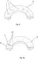
- the vortex diodes 7 or nozzles 20 are exchangeable. This is for tuning to actual process demands. Having a number of vortex diode or nozzle inserts of different internal dimensions, it is easy to mix up sizes or to lose one of the tiny inserts. This can be avoided if the vortex diodes 7 are designed into a single piece as shown in fig. 6 . Here all the vortex chambers 7 are milled out in a ring piece 9. There is an arrangement of O-rings or gaskets to prevents leakage even though it is not shown in the fig. 6 . The same kind of arrangement can also be used for nozzles 20. The central bores 21 of the vortex diodes 7 are formed in an exchangeable ring 8 shown in fig. 6a . There is an arrangement of O-rings or gaskets to prevent leakage even though it is not shown in the figs. 6 or 6a . The same kind of arrangement can also be used for plain nozzles 20.
- Fig. 4 shows a stability diagram with the second outlet flow rate and the concentration of yeast at the second outlet.
- Running the separator at a combination of second outlet flow rate and concentration in the instable region of the diagram leads to plugging of the outlet conduits 5.
- the diagram shows a dashed curve which represent stable operation without any clogging of the conduits.
- the line with dots on it is the stability limit curve under which there is a great risk of clogging of said conduits. This curve may be drawn up from experience.
- Fig. 5 shows a scheme of the centrifugal separator with control and regulation devices in an application for clarifying beer.
- Concentrate phase flow and density is measured by a flow transmitter 50 (FT) and a density transmitter 51 (DT) arranged in the second outlet 2 and the result signals are sent to a programmable logic controller 52 or PLC.
- the PLC 52 is receiving the signals from the flow transmitter 50 and the density transmitter 51 respectively.
- the flow transmitter and the density transmitter may be substituted for a Coriolis type mass flow meter from which measurements both flow and density can be derived.
- the PLC 52 is programmed to control a first control valve 53 arranged in the second hermetic outlet 2 for the heavy phase to keep the flow and density parameters in the stable area of the diagram in fig. 4 , preferably following the dashed line of fig. 4 . That is with some margin to the stability limit.
- the control line of fig. 4 is drawn as a straight line, but it can also be a curve.
- the PLC 52 may instead or also be programmed to control a second control valve 54 arranged in the first hermetic outlet 1 for the light phase.
Landscapes
- Centrifugal Separators (AREA)
- Distillation Of Fermentation Liquor, Processing Of Alcohols, Vinegar And Beer (AREA)
- Paper (AREA)
Abstract
Description
- The present invention relates to a centrifugal separator for separation of a liquid mixture into a heavy phase and a light phase and a method to control such a centrifugal separator.
- In a centrifugal separator for clarification of beer, having a sludge space where the separated heavy phase comprising yeast is collected, the yeast is ejected through discharges by intermittently opening outlets in the periphery of the separator bowl while the clarified beer is leaving the centrifugal separator through a hermetic outlet or a paring disc outlet. As the yeast concentration in the feed to the separator is far from constant it is difficult to optimize the operation to obtain best possible result. For example, when the yeast concentration is high, when taking feed from the bottom of the yeast tanks, frequent peripheral discharges are needed to avoid overfilling of the sludge space and leading to insufficient clarification. The throughput capacity of the separator is then limited by the discharge frequency needed. The turbidity of the clarified beer is often used as input signal for triggering discharges, by using PLC-control.
- An improvement of the centrifugal separator described above is disclosed in
US 9,186,687 - However, the manifold of concentrate pipes is an unstable configuration. If one pipe gets a disturbance in yeast concentration, for instance a slightly higher yeast concentration, the concentrate of this pipe becomes denser and more viscous. This leads to a flow reduction in that pipe relative to the other pipes of the manifold. The flow reduction leads to a further increase in yeast concentration in the pipe, and as a consequence, the disturbance is self-amplifying and growing in amplitude until the concentrate pipe clogs.
- The object of the present invention is to reduce the risk of clogging in such conduits transporting heavy phase, such as yeast concentrate, from a sludge space to an outlet.
- The above object is realized in a first aspect in that said centrifugal separator has a centrifugal separator bowl rotatable around an axis and encasing a separation space, and a sludge space radially outward of said separation space, comprising a hermetic inlet for feeding a liquid mixture to said separation space; a first hermetic outlet for a separated clarified light phase; a second hermetic outlet for a separated heavy phase; and a plurality of
outlet conduits 5 extending from an outer position in saidsludge space 12 to said second hermetic outlet; wherein each of the outlet conduits has a flow restriction in the form of a nozzle or vortex diode. - According to a further embodiment of the first aspect, said outlet conduits are at least partly shaped as pipes.
- According to a further embodiment of the first aspect, the cross-section of said outlet conduits is circular.
- According to a further embodiment of the first aspect, the flow restrictions are in the form of exchangeable pieces.
- According to a further embodiment of the first aspect, the flow restrictions are formed in a ring piece having one vortex diode or nozzle for each outlet conduit. According to a further embodiment of the first aspect, the second hermetic outlet for heavy phase has a mechanical seal of larger diameter than a mechanical seal on the first hermetic outlet for light phase.
- According to a further embodiment of the first aspect, the radius of the heavy phase outlet mechanical seal, and the outer radius of the disc stack, is larger than 20%.
- According to a further embodiment of the first aspect, the centrifugal separator bowl has a third outlet for intermittent discharge at its periphery.
- According to a further embodiment of the first aspect, a control valve is arranged in the second hermetic outlet.
- According to a further embodiment of the first aspect, a control valve is arranged in the first hermetic outlet.
- According to a further embodiment of the first aspect, at least one measuring device is arranged in the second hermetic outlet measuring density and flow rate, which device is connected to a programmable logic controller (PLC) and adapted to send data representing density and flow rate respectively, which PLC is adapted to process the data to determine if the combination of values of flow rate and density lies within a predetermined scope of values corresponding to a stable flow through said outlet conduits or not, wherein an actuator is adapted to manipulate one or both of said control valves in response to a correction signal sent by said PLC if said combination of values of flow rate and density does not lie within said predetermined scope.
- The above object is realized in a second aspect, by a method to control a centrifugal separator, in order to provide a stable flow through said outlet conduits, combinations of values of flow rate and density of the heavy phase is established where a stable flow through said outlet conduits are maintained, the flow rate and density of the heavy phase in said second hermetic outlet are measured continuously or intermittently and compared to said combinations of values by a PLC, the flow rate in said second hermetic outlet is regulated so a stable flow is maintained.
- According to a further embodiment of the second aspect, the PLC is set to follow a curve corresponding to combinations of flow rate and density in said second hermetic outlet, with a margin to a stability limit curve, under which stability limit curve the conduits may clog.
- Further features of, and advantages with, the invention will become apparent when studying the appended claims and the following detailed description.
- Various aspects and/or embodiments of the invention, including its particular features and advantages, will be readily understood from the example embodiments discussed in the following detailed description and the accompanying drawings, in which:
-
Fig. 1 illustrates a rotor of a centrifugal separator and inlet and outlets according to the present invention. -
Fig. 2 illustrates a detail of an embodiment of the centrifugal separator according to the present invention. -
Fig. 3 illustrates a detail of yet another embodiment of the centrifugal separator according to the present invention. -
Fig. 4 illustrates a graph disclosing a desired operation mode. -
Fig. 5 illustrates a schematic view of a centrifugal separator system using the invention. -
Fig. 6 and 6a illustrate an embodiment of vortex nozzles according to the present invention. -
Fig. 7 illustrates a centrifugal separator in which the present invention may be applied. -
Fig. 7 shows acentrifugal separator 100 for separating a fluid mixture into a light phase of clarified liquid and a heavy phase of sludge/sediment. Thecentrifugal separator 100 comprises aframe 102, ahollow spindle 11, which is rotatably supported by theframe 102 in abearing arrangement 103, and acentrifugal separator bowl 18 having arotor casing 105. Therotor casing 105 is fixedly adjoined to the axially upper end of thespindle 11 enabling adrive arrangement 104 to rotate thecentrifugal separator bowl 18 together with thespindle 11 around an axis (X) of rotation. Thedrive arrangement 104 may be a direct drive motor where the rotor of the motor is fixed to or is a part ofspindle 11 or it may involve a transmission transmitting rotational movement from a separate motor via a belt-drive or gear-drive. Therotor casing 105 encloses a separation space 106 in which astack 13 of separation discs is arranged in order to achieve effective separation of the fluid mixture that is processed. In the center of the separator bowl 18 adistributor 19a is arranged coaxially to thespindle 11. Thedistributor 19a is functioning as a nave on which saidstack 13 of separation discs is fitted centrally and coaxially with therotor casing 105. The separation discs of thestack 13 have a frustoconical shape and are examples of surface-enlarging inserts. Only a few separation discs are shown but astack 13 may for example contain above 100 separation discs, such as above 200 separation discs. In thecentrifugal separator bowl 18 radially outside of saidstack 13 of separation discs is asludge space 12 for receiving the heavier content of the fluid mixture. Therotor casing 105 has a mechanically hermetically sealedliquid outlet 1 for discharge of a separated liquid light phase, and aheavy phase outlet 2 for discharge of a phase of higher density than the separated liquid light phase. There is a number ofoutlet conduits 5 in the form of channels for transporting separated heavy phase from the separation space 106. The channels may be in the form of separate pipes, or may be channels which form part of the bowl wall. Theoutlet conduits 5 extend from a radially outer position of the separation space 106 to theheavy phase outlet 2. As can be seen in better detail inFig. 1 , theoutlet conduits 5 have aconduit inlet 5a arranged at the radially outer position and aconduit outlet 5b arranged at a radially inner position. Further theoutlet conduits 5 are arranged with an upward tilt relative the radial plane from theconduit inlet 5a to theconduit outlet 5b. Each of the outlet conduits has a flow restriction in the form of avortex diode 7. The flow restriction can also besimple nozzles 20 like inFig. 2 causing a pressure drop. Flow restrictions in form of vortex diodes are preferable as these show pressure drop reduction as viscosity increase, resulting in improved stability of the manifold consisting of a plurality ofoutlet conduits 5. A simple anozzle 20 has a viscosity independent pressure drop and does not work as well. Increasing pressure drop by just reducing cross section of theconduits 5 does not work as this gives increased pressure drop with increased concentration. - In
Fig. 3 theoutlet conduits 5 continues as separated channels out to the vicinity of the outer diameter of animpeller 15 comprising apump wheel 15a rotating with saidcentrifugal separator bowl 18, where theflow restrictions 7 in the form of vortex diodes 7 (or nozzles 20) are positioned at the end of theconduits 5 at the vicinity of outer diameter of thepump wheel 15a. - The vortex nozzles are thus placed in the
impeller 15 close to the periphery of the impeller to reduce the risk of cavitation or degassing, especially in beer separation. The pressure in the section with the smallest radius can thus be increased while keeping the stabilizing feature of the nozzles. For this to work it is necessary that the flow paths from all concentrate tubes are kept separate all the way up to thenozzles 20. - Commonly used separator outlet pump wheels are designed as standard centrifugal pump wheels having curved vanes. A pump wheel according to the invention differs from this as the
outlet conduits 5 continues as separate closed conduits all the way to the flow restriction at the outer diameter of the pump wheel. This flow restriction can be in the form of avortex diode 7 or just aplain nozzle 20. The part of theoutlet conduits 5 extending in the pump wheel can be in the form of curved channels and/or as radial channels. - In
Fig. 1 theoutlet conduits 5 are executed as pipes stretching out in thesludge space 12 to a diameter larger than the disc stack diameter. When clarifying beer the heavy phase flowing in theoutlet conduits 5 is yeast concentrate. - The
spindle 11 is hollow and has in its center parallell with the axis of rotation aninlet channel 4 for feeding the fluid mixture to be separated into saidseparator bowl 18. Saidinlet channel 4 leads the fluid mixture to thedistributor channels 19 which transport the fluid mixture from the center of the rotor out to the distributingholes 14 of the stack ofconical separator discs 13. Clarified liquid is taken out from the center of the disc stack and leaves the separator by theliquid outlet 1 for discharge of a separated liquid light phase. The heavier concentrate and sediment goes to thesludge space 12. Concentrate and sediment can leave thesludge space 12 either by thesecond outlet 2 or by discharge ports forintermittent discharge 3. The opening and closing of thedischarge ports 3 is managed by a hydraulically operated slidingbowl bottom 10. - The first and
second outlet mechanical seals inlet channel 4 also has a mechanical seal sealing between a stationary part of said inlet channel and a lower end of thehollow spindle 11, thus preventing communication between the inlet channel and the surroundings. This mechanical seal is not shown in this figure. - When adding the pressure drop caused by the
nozzles 20 orvortex diodes 7 to the pressure drop in theoutlet conduits 5 and the pressure needed to push the heavy phase concentrate against centrifugal force to the center of separator, it is advantageous to have the heavy phase outlet on a larger diameter of the centrifugal separator bowl than the light phase outlet. It is even preferable to have a heavy phase outlet mechanical seal with a diameter larger than normally, as when the diameter is set from flow rate considerations. It is particularly advantageous if the ratio between the radius of the heavy phase outlet mechanical seal, Rseal, and the outer radius of thedisc stack 13, Rdisc, is larger than 20%. - It is also possible to rearrange the design to have the inlet at the top of the separator and one of first or
second outlet hollow spindle 11. - The
vortex diodes 7 ornozzles 20 are exchangeable. This is for tuning to actual process demands. Having a number of vortex diode or nozzle inserts of different internal dimensions, it is easy to mix up sizes or to lose one of the tiny inserts. This can be avoided if thevortex diodes 7 are designed into a single piece as shown infig. 6 . Here all thevortex chambers 7 are milled out in aring piece 9. There is an arrangement of O-rings or gaskets to prevents leakage even though it is not shown in thefig. 6 . The same kind of arrangement can also be used fornozzles 20. The central bores 21 of thevortex diodes 7 are formed in anexchangeable ring 8 shown infig. 6a . There is an arrangement of O-rings or gaskets to prevent leakage even though it is not shown in thefigs. 6 or 6a . The same kind of arrangement can also be used forplain nozzles 20. -
Fig. 4 shows a stability diagram with the second outlet flow rate and the concentration of yeast at the second outlet. Running the separator at a combination of second outlet flow rate and concentration in the instable region of the diagram leads to plugging of theoutlet conduits 5. The diagram shows a dashed curve which represent stable operation without any clogging of the conduits. The line with dots on it is the stability limit curve under which there is a great risk of clogging of said conduits. This curve may be drawn up from experience.Fig. 5 shows a scheme of the centrifugal separator with control and regulation devices in an application for clarifying beer. Concentrate phase flow and density is measured by a flow transmitter 50 (FT) and a density transmitter 51 (DT) arranged in thesecond outlet 2 and the result signals are sent to aprogrammable logic controller 52 or PLC. ThePLC 52 is receiving the signals from theflow transmitter 50 and thedensity transmitter 51 respectively. - The flow transmitter and the density transmitter may be substituted for a Coriolis type mass flow meter from which measurements both flow and density can be derived.
- The
PLC 52 is programmed to control afirst control valve 53 arranged in the secondhermetic outlet 2 for the heavy phase to keep the flow and density parameters in the stable area of the diagram infig. 4 , preferably following the dashed line offig. 4 . That is with some margin to the stability limit. The control line offig. 4 is drawn as a straight line, but it can also be a curve. - The
PLC 52 may instead or also be programmed to control asecond control valve 54 arranged in the firsthermetic outlet 1 for the light phase. - The higher viability of the yeast/cell culture discharged by the second outlet makes it reusable for further fermentation, while cells leaving the separator through intermittent discharge are mostly dead. When reusing the concentrate in this way a lower concentration of the second outflow does not give a product loss of clarified first outlet liquid (beer).
- It is to be understood that the foregoing is illustrative of various example embodiments and that the invention is defined only by the appended claims. A person skilled in the art will realize that the example embodiments may be modified, and that different features of the example embodiments may be combined to create embodiments other than those described herein, without departing from the scope of the invention, as defined by the appended claims.
Claims (13)
- A centrifugal separator for clarification of a liquid mixture into a heavy phase and a light phase, having a centrifugal separator bowl rotatable around an axis (X) and encasing a separation space (106), and a sludge space (12) radially outward of said separation space, comprising
a hermetic inlet (4) for feeding a liquid mixture to said separation space (106);
a first hermetic outlet (1) for a separated clarified light phase;
a second hermetic outlet (2) for a separated heavy phase;
a plurality of outlet conduits (5) extending from an outer position in said sludge space (12) to said second hermetic outlet (2); wherein each of the outlet conduits (5) has a flow restriction in the form of a nozzle (20) or vortex diode (7). - A centrifugal separator according to claim 1, wherein said outlet conduits (5) are at least partly shaped as pipes.
- A centrifugal separator according to one of claims 1 or 2, wherein the cross-section of said outlet conduits (5) is circular.
- A centrifugal separator according to one of claims 1-3, wherein the flow restrictions (7, 20) are in the form of exchangeable pieces.
- A centrifugal separator according to claim 4, wherein the flow restrictions (7, 20) are formed in a ring piece (9) having one vortex diode (7) or nozzle (20) for each outlet conduit (5).
- A centrifugal separator according to one of the preceding claims, wherein the second hermetic outlet (2) for heavy phase has a mechanical seal (6b) of larger diameter than a mechanical seal (6a) on the first hermetic outlet (1) for light phase.
- A centrifugal separator according to claim 6, wherein the radius (Rseal) of the heavy phase outlet mechanical seal (6b), and the outer radius (Rdisc) of the disc stack (13), is larger than 20%.
- A centrifugal separator according to one of the preceding claims, wherein the centrifugal separator bowl (18) has a third outlet (3) for intermittent discharge at its periphery.
- A centrifugal separator according to one of the preceding claims, wherein a control valve (53) is arranged in the second hermetic outlet (2).
- A centrifugal separator according to one of the preceding claims, wherein a control valve (54) is arranged in the first hermetic outlet (1).
- A centrifugal separator according to claim 9, wherein at least one measuring device (50, 51) is arranged in the second hermetic outlet (2) measuring density and flow rate, which device is connected to a programmable logic controller (PLC) (52) and adapted to send data representing density and flow rate respectively, which PLC (52) is adapted to process the data to determine if the combination of values of flow rate and density lies within a predetermined scope of values corresponding to a stable flow through said outlet conduits (5) or not, wherein an actuator is adapted to manipulate one or both of said control valves (53, 54) in response to a correction signal sent by said PLC (52) if said combination of values of flow rate and density does not lie within said predetermined scope.
- A method to control a centrifugal separator according to one of claims 1-11, in order to provide a stable flow through said outlet conduits (5), combinations of values of flow rate and density of the heavy phase is established where a stable flow through said outlet conduits (5) are maintained, the flow rate and density of the heavy phase in said second hermetic outlet (2) are measured continuously or intermittently and compared to said combinations of values by said PLC (52), the flow rate in said second hermetic outlet (2) and/or said first hermetic outlet (3) is regulated so a stable flow is maintained.
- A method according to claims 12, wherein the PLC is set to follow a curve corresponding to combinations of flow rate and density in said second hermetic outlet (2), with a margin to a stability limit curve, under which stability limit curve the conduits (5) may clog.
Priority Applications (8)
| Application Number | Priority Date | Filing Date | Title |
|---|---|---|---|
| EP19199430.0A EP3797872B1 (en) | 2019-09-25 | 2019-09-25 | Centrifugal separator and a method to control of the same |
| US17/641,524 US12528091B2 (en) | 2019-09-25 | 2020-09-10 | Centrifugal separator having ring with outlet flow restrictions |
| AU2020353133A AU2020353133B2 (en) | 2019-09-25 | 2020-09-10 | Centrifugal separator and a method to control of the same |
| CN202080066980.9A CN114401793A (en) | 2019-09-25 | 2020-09-10 | Centrifugal separator and method for controlling the same |
| JP2022519297A JP7440624B2 (en) | 2019-09-25 | 2020-09-10 | Centrifuge and its control method |
| BR112022003733-3A BR112022003733B1 (en) | 2019-09-25 | 2020-09-10 | Centrifugal Separator, and Method for Controlling a Centrifugal Separator |
| PCT/EP2020/075297 WO2021058287A1 (en) | 2019-09-25 | 2020-09-10 | Centrifugal separator and a method to control of the same |
| NZ785439A NZ785439B2 (en) | 2020-09-10 | Centrifugal separator and a method to control of the same |
Applications Claiming Priority (1)
| Application Number | Priority Date | Filing Date | Title |
|---|---|---|---|
| EP19199430.0A EP3797872B1 (en) | 2019-09-25 | 2019-09-25 | Centrifugal separator and a method to control of the same |
Publications (2)
| Publication Number | Publication Date |
|---|---|
| EP3797872A1 true EP3797872A1 (en) | 2021-03-31 |
| EP3797872B1 EP3797872B1 (en) | 2024-04-10 |
Family
ID=68066718
Family Applications (1)
| Application Number | Title | Priority Date | Filing Date |
|---|---|---|---|
| EP19199430.0A Active EP3797872B1 (en) | 2019-09-25 | 2019-09-25 | Centrifugal separator and a method to control of the same |
Country Status (6)
| Country | Link |
|---|---|
| US (1) | US12528091B2 (en) |
| EP (1) | EP3797872B1 (en) |
| JP (1) | JP7440624B2 (en) |
| CN (1) | CN114401793A (en) |
| AU (1) | AU2020353133B2 (en) |
| WO (1) | WO2021058287A1 (en) |
Cited By (3)
| Publication number | Priority date | Publication date | Assignee | Title |
|---|---|---|---|---|
| EP4512530A1 (en) * | 2023-08-22 | 2025-02-26 | Alfa Laval Corporate AB | A centrifugal separator for separating a liquid mixture |
| USD1077219S1 (en) | 2022-07-17 | 2025-05-27 | Aso Llc | Nasal dilator with arms |
| EP4725612A1 (en) * | 2024-10-08 | 2026-04-15 | Alfa Laval Corporate AB | A method of separating a liquid feed mixture in a centrifugal separator and a centrifugal separator |
Families Citing this family (6)
| Publication number | Priority date | Publication date | Assignee | Title |
|---|---|---|---|---|
| EP4268966B1 (en) | 2022-04-29 | 2025-10-29 | Alfa Laval Corporate AB | A method of separating a liquid feed mixture comprising yeast |
| EP4268964B1 (en) | 2022-04-29 | 2025-01-22 | Alfa Laval Corporate AB | A centrifugal separator |
| EP4268965B1 (en) | 2022-04-29 | 2025-01-22 | Alfa Laval Corporate AB | A centrifugal separator |
| US11649624B1 (en) * | 2022-09-03 | 2023-05-16 | Kuwait University | Effluent dispenser system |
| EP4424170A1 (en) * | 2023-03-03 | 2024-09-04 | Alfa Laval Corporate AB | Process for extracting starch, fibres and protein from a plant-based raw material |
| EP4512529A1 (en) | 2023-08-22 | 2025-02-26 | Alfa Laval Corporate AB | A method of separating a liquid mixture in a centrifugal separator |
Citations (7)
| Publication number | Priority date | Publication date | Assignee | Title |
|---|---|---|---|---|
| US3482771A (en) * | 1967-05-18 | 1969-12-09 | Alfa Laval Ab | Sludge centrifuge |
| US5041075A (en) * | 1988-03-12 | 1991-08-20 | Westfalia Separator Ag | Continuous-operation centrifuge drum for concentrating suspended solids |
| US6319186B1 (en) * | 1998-08-24 | 2001-11-20 | Alfa Laval Ab | Method and a device for cleaning of a centrifugal separator |
| US20070117706A1 (en) * | 2003-12-11 | 2007-05-24 | Alfa Laval Corporate Ab | Centrifugal separator |
| WO2011004007A1 (en) * | 2009-07-10 | 2011-01-13 | Gea Westfalia Separator Gmbh | Centrifuge comprising a centrifugal drum rotatable about a rotational axis |
| US9186687B2 (en) | 2010-01-29 | 2015-11-17 | Alfa Laval Corporate Ab | Centrifugal separator with pressure or recirculation control or monitoring devices |
| EP3207995A1 (en) * | 2016-02-22 | 2017-08-23 | Alfa Laval Corporate AB | Centrifugal separator having an intermittent discharge system |
Family Cites Families (16)
| Publication number | Priority date | Publication date | Assignee | Title |
|---|---|---|---|---|
| US2107035A (en) * | 1934-02-16 | 1938-02-01 | Laval Separator Co De | Closed centrifugal separator |
| SE374989B (en) | 1973-05-29 | 1975-04-07 | Alfa Laval Ab | |
| NL8801848A (en) | 1988-07-21 | 1990-02-16 | Stork Amsterdam | METHOD AND APPARATUS FOR PREPARING MILK WITH PRE-PREFERRED FAT CONTENT |
| DE19820870A1 (en) | 1998-05-09 | 1999-11-18 | Westfalia Separator Ag | Whey separation during cheese production |
| DE10361520C5 (en) | 2003-12-23 | 2012-02-23 | Gea Westfalia Separator Gmbh | Method for preventing clogging of the flow paths of a separator |
| DE102008051499A1 (en) | 2008-10-13 | 2010-04-15 | Gea Westfalia Separator Gmbh | Process for reducing the pulp content of pulpy fruit juices |
| US8657913B2 (en) * | 2009-07-10 | 2014-02-25 | Alfa Laval Corporate Ab | Gas cleaning separator |
| CN201644237U (en) * | 2010-03-09 | 2010-11-24 | 辽宁双联化工制药机械有限公司 | Disc separator for aging oil treatment in oil field |
| EP2431583A1 (en) * | 2010-09-15 | 2012-03-21 | Alfa Laval Corporate AB | A device and method for cleaning crankcase gas |
| DE102012105828A1 (en) | 2012-07-02 | 2014-01-02 | Gea Mechanical Equipment Gmbh | Process for working up an emulsion formed in the hydrometallurgical recovery of a metal |
| ITAN20120088A1 (en) * | 2012-07-12 | 2014-01-13 | Pieralisi Maip Societa Per Azioni | CENTRIFUGAL OR DECANTER SEPARATOR PROVIDED WITH A PERFECT CLOSING SYSTEM. |
| SE538684C2 (en) | 2014-12-10 | 2016-10-18 | Göran Hofstedt Anders | Procedure and plant for washing raw soap |
| EP3319453B1 (en) | 2015-07-09 | 2021-09-01 | Tetra Laval Holdings & Finance S.A. | Method and device for in-line fat standardization of a dairy product |
| PL3167721T3 (en) | 2015-11-13 | 2019-01-31 | Tetra Laval Holdings & Finance | Method for discharge control of a separator, and a separator with discharge control |
| CN105363570A (en) * | 2015-12-15 | 2016-03-02 | 宜兴市华鼎粮食机械有限公司 | Three-phase disk centrifuge |
| EP3315182A1 (en) | 2016-10-31 | 2018-05-02 | Pratt & Whitney Canada Corp. | Centrifugal separator |
-
2019
- 2019-09-25 EP EP19199430.0A patent/EP3797872B1/en active Active
-
2020
- 2020-09-10 JP JP2022519297A patent/JP7440624B2/en active Active
- 2020-09-10 WO PCT/EP2020/075297 patent/WO2021058287A1/en not_active Ceased
- 2020-09-10 US US17/641,524 patent/US12528091B2/en active Active
- 2020-09-10 CN CN202080066980.9A patent/CN114401793A/en active Pending
- 2020-09-10 AU AU2020353133A patent/AU2020353133B2/en active Active
Patent Citations (7)
| Publication number | Priority date | Publication date | Assignee | Title |
|---|---|---|---|---|
| US3482771A (en) * | 1967-05-18 | 1969-12-09 | Alfa Laval Ab | Sludge centrifuge |
| US5041075A (en) * | 1988-03-12 | 1991-08-20 | Westfalia Separator Ag | Continuous-operation centrifuge drum for concentrating suspended solids |
| US6319186B1 (en) * | 1998-08-24 | 2001-11-20 | Alfa Laval Ab | Method and a device for cleaning of a centrifugal separator |
| US20070117706A1 (en) * | 2003-12-11 | 2007-05-24 | Alfa Laval Corporate Ab | Centrifugal separator |
| WO2011004007A1 (en) * | 2009-07-10 | 2011-01-13 | Gea Westfalia Separator Gmbh | Centrifuge comprising a centrifugal drum rotatable about a rotational axis |
| US9186687B2 (en) | 2010-01-29 | 2015-11-17 | Alfa Laval Corporate Ab | Centrifugal separator with pressure or recirculation control or monitoring devices |
| EP3207995A1 (en) * | 2016-02-22 | 2017-08-23 | Alfa Laval Corporate AB | Centrifugal separator having an intermittent discharge system |
Cited By (5)
| Publication number | Priority date | Publication date | Assignee | Title |
|---|---|---|---|---|
| USD1077219S1 (en) | 2022-07-17 | 2025-05-27 | Aso Llc | Nasal dilator with arms |
| EP4512530A1 (en) * | 2023-08-22 | 2025-02-26 | Alfa Laval Corporate AB | A centrifugal separator for separating a liquid mixture |
| WO2025040443A1 (en) * | 2023-08-22 | 2025-02-27 | Alfa Laval Corporate Ab | A centrifugal separator for separating a liquid mixture |
| EP4725612A1 (en) * | 2024-10-08 | 2026-04-15 | Alfa Laval Corporate AB | A method of separating a liquid feed mixture in a centrifugal separator and a centrifugal separator |
| WO2026077610A1 (en) * | 2024-10-08 | 2026-04-16 | Alfa Laval Corporate Ab | A method of separating a liquid feed mixture in a centrifugal separator and a centrifugal separator |
Also Published As
| Publication number | Publication date |
|---|---|
| AU2020353133A1 (en) | 2022-04-14 |
| US20220331817A1 (en) | 2022-10-20 |
| JP7440624B2 (en) | 2024-02-28 |
| JP2022550740A (en) | 2022-12-05 |
| CN114401793A (en) | 2022-04-26 |
| US12528091B2 (en) | 2026-01-20 |
| WO2021058287A1 (en) | 2021-04-01 |
| NZ785439A (en) | 2024-11-29 |
| EP3797872B1 (en) | 2024-04-10 |
| AU2020353133B2 (en) | 2023-04-27 |
| BR112022003733A2 (en) | 2022-05-31 |
Similar Documents
| Publication | Publication Date | Title |
|---|---|---|
| EP3797872B1 (en) | Centrifugal separator and a method to control of the same | |
| US8628458B2 (en) | Three-phase separator having an overflow outlet for one phase and a centripetal pump for another phase | |
| CN102869450B (en) | Device and method for monitoring and adjusting the radial position of an interface layer in a nozzle centrifuge | |
| EP2496357B1 (en) | Hermetic centrifugal separator | |
| US7134991B2 (en) | Annular centrifugal extractor with embedded stirring rotor | |
| US8523749B2 (en) | Three-phase solid bowl screw centrifuge and method of controlling the separating process | |
| RO119347B1 (en) | Discharging device and centrifugal separator | |
| EP3501659B1 (en) | Separating milk | |
| CN107847946A (en) | Separation barrel and separator | |
| KR102707664B1 (en) | Complex centrifuge with improved oil separation efficiency | |
| EP0164866A1 (en) | Maintaining liquid level in a centrifugal separator | |
| CN102413940A (en) | Centrifugal separator and method for separation | |
| EP4268966B1 (en) | A method of separating a liquid feed mixture comprising yeast | |
| BR112022003733B1 (en) | Centrifugal Separator, and Method for Controlling a Centrifugal Separator | |
| US20060286206A1 (en) | Method and device for adjusting the sediment content of a drink | |
| AU2022327488A1 (en) | Centrifuge, and method for operating said centrifuge | |
| EP4268965B1 (en) | A centrifugal separator | |
| EP4268964B1 (en) | A centrifugal separator | |
| EP4650054A1 (en) | Priority control | |
| NZ785439B2 (en) | Centrifugal separator and a method to control of the same | |
| AU2010315951B2 (en) | Hermetic centrifugal separator | |
| CN119451751A (en) | System for separating liquid feed mixtures |
Legal Events
| Date | Code | Title | Description |
|---|---|---|---|
| PUAI | Public reference made under article 153(3) epc to a published international application that has entered the european phase |
Free format text: ORIGINAL CODE: 0009012 |
|
| STAA | Information on the status of an ep patent application or granted ep patent |
Free format text: STATUS: REQUEST FOR EXAMINATION WAS MADE |
|
| 17P | Request for examination filed |
Effective date: 20190925 |
|
| AK | Designated contracting states |
Kind code of ref document: A1 Designated state(s): AL AT BE BG CH CY CZ DE DK EE ES FI FR GB GR HR HU IE IS IT LI LT LU LV MC MK MT NL NO PL PT RO RS SE SI SK SM TR |
|
| AX | Request for extension of the european patent |
Extension state: BA ME |
|
| RIN1 | Information on inventor provided before grant (corrected) |
Inventor name: TOERNBLOM, OLLE Inventor name: BORGSTROEM, LEONARD |
|
| GRAP | Despatch of communication of intention to grant a patent |
Free format text: ORIGINAL CODE: EPIDOSNIGR1 |
|
| STAA | Information on the status of an ep patent application or granted ep patent |
Free format text: STATUS: GRANT OF PATENT IS INTENDED |
|
| INTG | Intention to grant announced |
Effective date: 20231019 |
|
| GRAJ | Information related to disapproval of communication of intention to grant by the applicant or resumption of examination proceedings by the epo deleted |
Free format text: ORIGINAL CODE: EPIDOSDIGR1 |
|
| STAA | Information on the status of an ep patent application or granted ep patent |
Free format text: STATUS: REQUEST FOR EXAMINATION WAS MADE |
|
| P01 | Opt-out of the competence of the unified patent court (upc) registered |
Effective date: 20231208 |
|
| GRAP | Despatch of communication of intention to grant a patent |
Free format text: ORIGINAL CODE: EPIDOSNIGR1 |
|
| STAA | Information on the status of an ep patent application or granted ep patent |
Free format text: STATUS: GRANT OF PATENT IS INTENDED |
|
| INTC | Intention to grant announced (deleted) | ||
| INTG | Intention to grant announced |
Effective date: 20240125 |
|
| RAP3 | Party data changed (applicant data changed or rights of an application transferred) |
Owner name: ALFA LAVAL CORPORATE AB |
|
| GRAS | Grant fee paid |
Free format text: ORIGINAL CODE: EPIDOSNIGR3 |
|
| GRAA | (expected) grant |
Free format text: ORIGINAL CODE: 0009210 |
|
| STAA | Information on the status of an ep patent application or granted ep patent |
Free format text: STATUS: THE PATENT HAS BEEN GRANTED |
|
| AK | Designated contracting states |
Kind code of ref document: B1 Designated state(s): AL AT BE BG CH CY CZ DE DK EE ES FI FR GB GR HR HU IE IS IT LI LT LU LV MC MK MT NL NO PL PT RO RS SE SI SK SM TR |
|
| REG | Reference to a national code |
Ref country code: GB Ref legal event code: FG4D |
|
| REG | Reference to a national code |
Ref country code: CH Ref legal event code: EP |
|
| REG | Reference to a national code |
Ref country code: DE Ref legal event code: R096 Ref document number: 602019049889 Country of ref document: DE |
|
| REG | Reference to a national code |
Ref country code: IE Ref legal event code: FG4D |
|
| REG | Reference to a national code |
Ref country code: LT Ref legal event code: MG9D |
|
| REG | Reference to a national code |
Ref country code: NL Ref legal event code: MP Effective date: 20240410 |
|
| REG | Reference to a national code |
Ref country code: AT Ref legal event code: MK05 Ref document number: 1674386 Country of ref document: AT Kind code of ref document: T Effective date: 20240410 |
|
| PG25 | Lapsed in a contracting state [announced via postgrant information from national office to epo] |
Ref country code: NL Free format text: LAPSE BECAUSE OF FAILURE TO SUBMIT A TRANSLATION OF THE DESCRIPTION OR TO PAY THE FEE WITHIN THE PRESCRIBED TIME-LIMIT Effective date: 20240410 |
|
| PG25 | Lapsed in a contracting state [announced via postgrant information from national office to epo] |
Ref country code: NL Free format text: LAPSE BECAUSE OF FAILURE TO SUBMIT A TRANSLATION OF THE DESCRIPTION OR TO PAY THE FEE WITHIN THE PRESCRIBED TIME-LIMIT Effective date: 20240410 |
|
| PG25 | Lapsed in a contracting state [announced via postgrant information from national office to epo] |
Ref country code: IS Free format text: LAPSE BECAUSE OF FAILURE TO SUBMIT A TRANSLATION OF THE DESCRIPTION OR TO PAY THE FEE WITHIN THE PRESCRIBED TIME-LIMIT Effective date: 20240810 |
|
| PG25 | Lapsed in a contracting state [announced via postgrant information from national office to epo] |
Ref country code: BG Free format text: LAPSE BECAUSE OF FAILURE TO SUBMIT A TRANSLATION OF THE DESCRIPTION OR TO PAY THE FEE WITHIN THE PRESCRIBED TIME-LIMIT Effective date: 20240410 |
|
| PG25 | Lapsed in a contracting state [announced via postgrant information from national office to epo] |
Ref country code: FI Free format text: LAPSE BECAUSE OF FAILURE TO SUBMIT A TRANSLATION OF THE DESCRIPTION OR TO PAY THE FEE WITHIN THE PRESCRIBED TIME-LIMIT Effective date: 20240410 Ref country code: HR Free format text: LAPSE BECAUSE OF FAILURE TO SUBMIT A TRANSLATION OF THE DESCRIPTION OR TO PAY THE FEE WITHIN THE PRESCRIBED TIME-LIMIT Effective date: 20240410 |
|
| PG25 | Lapsed in a contracting state [announced via postgrant information from national office to epo] |
Ref country code: GR Free format text: LAPSE BECAUSE OF FAILURE TO SUBMIT A TRANSLATION OF THE DESCRIPTION OR TO PAY THE FEE WITHIN THE PRESCRIBED TIME-LIMIT Effective date: 20240711 |
|
| PG25 | Lapsed in a contracting state [announced via postgrant information from national office to epo] |
Ref country code: PT Free format text: LAPSE BECAUSE OF FAILURE TO SUBMIT A TRANSLATION OF THE DESCRIPTION OR TO PAY THE FEE WITHIN THE PRESCRIBED TIME-LIMIT Effective date: 20240812 |
|
| PG25 | Lapsed in a contracting state [announced via postgrant information from national office to epo] |
Ref country code: ES Free format text: LAPSE BECAUSE OF FAILURE TO SUBMIT A TRANSLATION OF THE DESCRIPTION OR TO PAY THE FEE WITHIN THE PRESCRIBED TIME-LIMIT Effective date: 20240410 |
|
| PG25 | Lapsed in a contracting state [announced via postgrant information from national office to epo] |
Ref country code: AT Free format text: LAPSE BECAUSE OF FAILURE TO SUBMIT A TRANSLATION OF THE DESCRIPTION OR TO PAY THE FEE WITHIN THE PRESCRIBED TIME-LIMIT Effective date: 20240410 |
|
| PG25 | Lapsed in a contracting state [announced via postgrant information from national office to epo] |
Ref country code: PL Free format text: LAPSE BECAUSE OF FAILURE TO SUBMIT A TRANSLATION OF THE DESCRIPTION OR TO PAY THE FEE WITHIN THE PRESCRIBED TIME-LIMIT Effective date: 20240410 |
|
| PG25 | Lapsed in a contracting state [announced via postgrant information from national office to epo] |
Ref country code: LV Free format text: LAPSE BECAUSE OF FAILURE TO SUBMIT A TRANSLATION OF THE DESCRIPTION OR TO PAY THE FEE WITHIN THE PRESCRIBED TIME-LIMIT Effective date: 20240410 |
|
| PG25 | Lapsed in a contracting state [announced via postgrant information from national office to epo] |
Ref country code: PT Free format text: LAPSE BECAUSE OF FAILURE TO SUBMIT A TRANSLATION OF THE DESCRIPTION OR TO PAY THE FEE WITHIN THE PRESCRIBED TIME-LIMIT Effective date: 20240812 Ref country code: PL Free format text: LAPSE BECAUSE OF FAILURE TO SUBMIT A TRANSLATION OF THE DESCRIPTION OR TO PAY THE FEE WITHIN THE PRESCRIBED TIME-LIMIT Effective date: 20240410 Ref country code: NO Free format text: LAPSE BECAUSE OF FAILURE TO SUBMIT A TRANSLATION OF THE DESCRIPTION OR TO PAY THE FEE WITHIN THE PRESCRIBED TIME-LIMIT Effective date: 20240710 Ref country code: LV Free format text: LAPSE BECAUSE OF FAILURE TO SUBMIT A TRANSLATION OF THE DESCRIPTION OR TO PAY THE FEE WITHIN THE PRESCRIBED TIME-LIMIT Effective date: 20240410 Ref country code: IS Free format text: LAPSE BECAUSE OF FAILURE TO SUBMIT A TRANSLATION OF THE DESCRIPTION OR TO PAY THE FEE WITHIN THE PRESCRIBED TIME-LIMIT Effective date: 20240810 Ref country code: HR Free format text: LAPSE BECAUSE OF FAILURE TO SUBMIT A TRANSLATION OF THE DESCRIPTION OR TO PAY THE FEE WITHIN THE PRESCRIBED TIME-LIMIT Effective date: 20240410 Ref country code: GR Free format text: LAPSE BECAUSE OF FAILURE TO SUBMIT A TRANSLATION OF THE DESCRIPTION OR TO PAY THE FEE WITHIN THE PRESCRIBED TIME-LIMIT Effective date: 20240711 Ref country code: FI Free format text: LAPSE BECAUSE OF FAILURE TO SUBMIT A TRANSLATION OF THE DESCRIPTION OR TO PAY THE FEE WITHIN THE PRESCRIBED TIME-LIMIT Effective date: 20240410 Ref country code: ES Free format text: LAPSE BECAUSE OF FAILURE TO SUBMIT A TRANSLATION OF THE DESCRIPTION OR TO PAY THE FEE WITHIN THE PRESCRIBED TIME-LIMIT Effective date: 20240410 Ref country code: BG Free format text: LAPSE BECAUSE OF FAILURE TO SUBMIT A TRANSLATION OF THE DESCRIPTION OR TO PAY THE FEE WITHIN THE PRESCRIBED TIME-LIMIT Effective date: 20240410 Ref country code: AT Free format text: LAPSE BECAUSE OF FAILURE TO SUBMIT A TRANSLATION OF THE DESCRIPTION OR TO PAY THE FEE WITHIN THE PRESCRIBED TIME-LIMIT Effective date: 20240410 Ref country code: RS Free format text: LAPSE BECAUSE OF FAILURE TO SUBMIT A TRANSLATION OF THE DESCRIPTION OR TO PAY THE FEE WITHIN THE PRESCRIBED TIME-LIMIT Effective date: 20240710 |
|
| REG | Reference to a national code |
Ref country code: DE Ref legal event code: R097 Ref document number: 602019049889 Country of ref document: DE |
|
| PG25 | Lapsed in a contracting state [announced via postgrant information from national office to epo] |
Ref country code: DK Free format text: LAPSE BECAUSE OF FAILURE TO SUBMIT A TRANSLATION OF THE DESCRIPTION OR TO PAY THE FEE WITHIN THE PRESCRIBED TIME-LIMIT Effective date: 20240410 |
|
| PG25 | Lapsed in a contracting state [announced via postgrant information from national office to epo] |
Ref country code: EE Free format text: LAPSE BECAUSE OF FAILURE TO SUBMIT A TRANSLATION OF THE DESCRIPTION OR TO PAY THE FEE WITHIN THE PRESCRIBED TIME-LIMIT Effective date: 20240410 |
|
| PG25 | Lapsed in a contracting state [announced via postgrant information from national office to epo] |
Ref country code: CZ Free format text: LAPSE BECAUSE OF FAILURE TO SUBMIT A TRANSLATION OF THE DESCRIPTION OR TO PAY THE FEE WITHIN THE PRESCRIBED TIME-LIMIT Effective date: 20240410 |
|
| PG25 | Lapsed in a contracting state [announced via postgrant information from national office to epo] |
Ref country code: RO Free format text: LAPSE BECAUSE OF FAILURE TO SUBMIT A TRANSLATION OF THE DESCRIPTION OR TO PAY THE FEE WITHIN THE PRESCRIBED TIME-LIMIT Effective date: 20240410 Ref country code: SK Free format text: LAPSE BECAUSE OF FAILURE TO SUBMIT A TRANSLATION OF THE DESCRIPTION OR TO PAY THE FEE WITHIN THE PRESCRIBED TIME-LIMIT Effective date: 20240410 |
|
| PG25 | Lapsed in a contracting state [announced via postgrant information from national office to epo] |
Ref country code: SM Free format text: LAPSE BECAUSE OF FAILURE TO SUBMIT A TRANSLATION OF THE DESCRIPTION OR TO PAY THE FEE WITHIN THE PRESCRIBED TIME-LIMIT Effective date: 20240410 |
|
| PG25 | Lapsed in a contracting state [announced via postgrant information from national office to epo] |
Ref country code: SM Free format text: LAPSE BECAUSE OF FAILURE TO SUBMIT A TRANSLATION OF THE DESCRIPTION OR TO PAY THE FEE WITHIN THE PRESCRIBED TIME-LIMIT Effective date: 20240410 Ref country code: SK Free format text: LAPSE BECAUSE OF FAILURE TO SUBMIT A TRANSLATION OF THE DESCRIPTION OR TO PAY THE FEE WITHIN THE PRESCRIBED TIME-LIMIT Effective date: 20240410 Ref country code: RO Free format text: LAPSE BECAUSE OF FAILURE TO SUBMIT A TRANSLATION OF THE DESCRIPTION OR TO PAY THE FEE WITHIN THE PRESCRIBED TIME-LIMIT Effective date: 20240410 Ref country code: EE Free format text: LAPSE BECAUSE OF FAILURE TO SUBMIT A TRANSLATION OF THE DESCRIPTION OR TO PAY THE FEE WITHIN THE PRESCRIBED TIME-LIMIT Effective date: 20240410 Ref country code: DK Free format text: LAPSE BECAUSE OF FAILURE TO SUBMIT A TRANSLATION OF THE DESCRIPTION OR TO PAY THE FEE WITHIN THE PRESCRIBED TIME-LIMIT Effective date: 20240410 Ref country code: CZ Free format text: LAPSE BECAUSE OF FAILURE TO SUBMIT A TRANSLATION OF THE DESCRIPTION OR TO PAY THE FEE WITHIN THE PRESCRIBED TIME-LIMIT Effective date: 20240410 |
|
| PG25 | Lapsed in a contracting state [announced via postgrant information from national office to epo] |
Ref country code: IT Free format text: LAPSE BECAUSE OF FAILURE TO SUBMIT A TRANSLATION OF THE DESCRIPTION OR TO PAY THE FEE WITHIN THE PRESCRIBED TIME-LIMIT Effective date: 20240410 |
|
| PLBE | No opposition filed within time limit |
Free format text: ORIGINAL CODE: 0009261 |
|
| STAA | Information on the status of an ep patent application or granted ep patent |
Free format text: STATUS: NO OPPOSITION FILED WITHIN TIME LIMIT |
|
| 26N | No opposition filed |
Effective date: 20250113 |
|
| PG25 | Lapsed in a contracting state [announced via postgrant information from national office to epo] |
Ref country code: SI Free format text: LAPSE BECAUSE OF FAILURE TO SUBMIT A TRANSLATION OF THE DESCRIPTION OR TO PAY THE FEE WITHIN THE PRESCRIBED TIME-LIMIT Effective date: 20240410 Ref country code: MC Free format text: LAPSE BECAUSE OF FAILURE TO SUBMIT A TRANSLATION OF THE DESCRIPTION OR TO PAY THE FEE WITHIN THE PRESCRIBED TIME-LIMIT Effective date: 20240410 |
|
| REG | Reference to a national code |
Ref country code: CH Ref legal event code: PL |
|
| PG25 | Lapsed in a contracting state [announced via postgrant information from national office to epo] |
Ref country code: LU Free format text: LAPSE BECAUSE OF NON-PAYMENT OF DUE FEES Effective date: 20240925 |
|
| GBPC | Gb: european patent ceased through non-payment of renewal fee |
Effective date: 20240925 |
|
| PG25 | Lapsed in a contracting state [announced via postgrant information from national office to epo] |
Ref country code: GB Free format text: LAPSE BECAUSE OF NON-PAYMENT OF DUE FEES Effective date: 20240925 |
|
| PG25 | Lapsed in a contracting state [announced via postgrant information from national office to epo] |
Ref country code: FR Free format text: LAPSE BECAUSE OF NON-PAYMENT OF DUE FEES Effective date: 20240930 |
|
| PG25 | Lapsed in a contracting state [announced via postgrant information from national office to epo] |
Ref country code: CH Free format text: LAPSE BECAUSE OF NON-PAYMENT OF DUE FEES Effective date: 20240930 |
|
| PG25 | Lapsed in a contracting state [announced via postgrant information from national office to epo] |
Ref country code: IE Free format text: LAPSE BECAUSE OF NON-PAYMENT OF DUE FEES Effective date: 20240925 |
|
| PG25 | Lapsed in a contracting state [announced via postgrant information from national office to epo] |
Ref country code: SE Free format text: LAPSE BECAUSE OF FAILURE TO SUBMIT A TRANSLATION OF THE DESCRIPTION OR TO PAY THE FEE WITHIN THE PRESCRIBED TIME-LIMIT Effective date: 20240410 |
|
| PGFP | Annual fee paid to national office [announced via postgrant information from national office to epo] |
Ref country code: DE Payment date: 20250702 Year of fee payment: 7 |
|
| PGFP | Annual fee paid to national office [announced via postgrant information from national office to epo] |
Ref country code: BE Payment date: 20250703 Year of fee payment: 7 |
|
| PG25 | Lapsed in a contracting state [announced via postgrant information from national office to epo] |
Ref country code: CY Free format text: LAPSE BECAUSE OF FAILURE TO SUBMIT A TRANSLATION OF THE DESCRIPTION OR TO PAY THE FEE WITHIN THE PRESCRIBED TIME-LIMIT; INVALID AB INITIO Effective date: 20190925 |
|
| PG25 | Lapsed in a contracting state [announced via postgrant information from national office to epo] |
Ref country code: HU Free format text: LAPSE BECAUSE OF FAILURE TO SUBMIT A TRANSLATION OF THE DESCRIPTION OR TO PAY THE FEE WITHIN THE PRESCRIBED TIME-LIMIT; INVALID AB INITIO Effective date: 20190925 |