EP3797631A1 - Shoe sole and shoe - Google Patents
Shoe sole and shoe Download PDFInfo
- Publication number
- EP3797631A1 EP3797631A1 EP18944849.1A EP18944849A EP3797631A1 EP 3797631 A1 EP3797631 A1 EP 3797631A1 EP 18944849 A EP18944849 A EP 18944849A EP 3797631 A1 EP3797631 A1 EP 3797631A1
- Authority
- EP
- European Patent Office
- Prior art keywords
- shoe sole
- surface part
- shoe
- midsole
- virtual
- Prior art date
- Legal status (The legal status is an assumption and is not a legal conclusion. Google has not performed a legal analysis and makes no representation as to the accuracy of the status listed.)
- Granted
Links
Images






Classifications
-
- A—HUMAN NECESSITIES
- A43—FOOTWEAR
- A43B—CHARACTERISTIC FEATURES OF FOOTWEAR; PARTS OF FOOTWEAR
- A43B13/00—Soles; Sole-and-heel integral units
- A43B13/02—Soles; Sole-and-heel integral units characterised by the material
- A43B13/12—Soles with several layers of different materials
- A43B13/125—Soles with several layers of different materials characterised by the midsole or middle layer
- A43B13/127—Soles with several layers of different materials characterised by the midsole or middle layer the midsole being multilayer
-
- A—HUMAN NECESSITIES
- A43—FOOTWEAR
- A43B—CHARACTERISTIC FEATURES OF FOOTWEAR; PARTS OF FOOTWEAR
- A43B13/00—Soles; Sole-and-heel integral units
- A43B13/14—Soles; Sole-and-heel integral units characterised by the constructive form
-
- A—HUMAN NECESSITIES
- A43—FOOTWEAR
- A43B—CHARACTERISTIC FEATURES OF FOOTWEAR; PARTS OF FOOTWEAR
- A43B13/00—Soles; Sole-and-heel integral units
- A43B13/14—Soles; Sole-and-heel integral units characterised by the constructive form
- A43B13/143—Soles; Sole-and-heel integral units characterised by the constructive form provided with wedged, concave or convex end portions, e.g. for improving roll-off of the foot
- A43B13/145—Convex portions, e.g. with a bump or projection, e.g. 'Masai' type shoes
-
- A—HUMAN NECESSITIES
- A43—FOOTWEAR
- A43B—CHARACTERISTIC FEATURES OF FOOTWEAR; PARTS OF FOOTWEAR
- A43B13/00—Soles; Sole-and-heel integral units
- A43B13/14—Soles; Sole-and-heel integral units characterised by the constructive form
- A43B13/18—Resilient soles
- A43B13/187—Resiliency achieved by the features of the material, e.g. foam, non liquid materials
- A43B13/188—Differential cushioning regions
-
- A—HUMAN NECESSITIES
- A43—FOOTWEAR
- A43B—CHARACTERISTIC FEATURES OF FOOTWEAR; PARTS OF FOOTWEAR
- A43B7/00—Footwear with health or hygienic arrangements
- A43B7/14—Footwear with health or hygienic arrangements with foot-supporting parts
- A43B7/1405—Footwear with health or hygienic arrangements with foot-supporting parts with pads or holes on one or more locations, or having an anatomical or curved form
- A43B7/1415—Footwear with health or hygienic arrangements with foot-supporting parts with pads or holes on one or more locations, or having an anatomical or curved form characterised by the location under the foot
- A43B7/1425—Footwear with health or hygienic arrangements with foot-supporting parts with pads or holes on one or more locations, or having an anatomical or curved form characterised by the location under the foot situated under the ball of the foot, i.e. the joint between the first metatarsal and first phalange
-
- A—HUMAN NECESSITIES
- A43—FOOTWEAR
- A43B—CHARACTERISTIC FEATURES OF FOOTWEAR; PARTS OF FOOTWEAR
- A43B7/00—Footwear with health or hygienic arrangements
- A43B7/14—Footwear with health or hygienic arrangements with foot-supporting parts
- A43B7/1405—Footwear with health or hygienic arrangements with foot-supporting parts with pads or holes on one or more locations, or having an anatomical or curved form
- A43B7/1415—Footwear with health or hygienic arrangements with foot-supporting parts with pads or holes on one or more locations, or having an anatomical or curved form characterised by the location under the foot
- A43B7/1435—Footwear with health or hygienic arrangements with foot-supporting parts with pads or holes on one or more locations, or having an anatomical or curved form characterised by the location under the foot situated under the joint between the fifth phalange and the fifth metatarsal bone
-
- A—HUMAN NECESSITIES
- A43—FOOTWEAR
- A43B—CHARACTERISTIC FEATURES OF FOOTWEAR; PARTS OF FOOTWEAR
- A43B7/00—Footwear with health or hygienic arrangements
- A43B7/14—Footwear with health or hygienic arrangements with foot-supporting parts
- A43B7/1405—Footwear with health or hygienic arrangements with foot-supporting parts with pads or holes on one or more locations, or having an anatomical or curved form
- A43B7/1415—Footwear with health or hygienic arrangements with foot-supporting parts with pads or holes on one or more locations, or having an anatomical or curved form characterised by the location under the foot
- A43B7/144—Footwear with health or hygienic arrangements with foot-supporting parts with pads or holes on one or more locations, or having an anatomical or curved form characterised by the location under the foot situated under the heel, i.e. the calcaneus bone
-
- A—HUMAN NECESSITIES
- A43—FOOTWEAR
- A43B—CHARACTERISTIC FEATURES OF FOOTWEAR; PARTS OF FOOTWEAR
- A43B7/00—Footwear with health or hygienic arrangements
- A43B7/14—Footwear with health or hygienic arrangements with foot-supporting parts
- A43B7/1405—Footwear with health or hygienic arrangements with foot-supporting parts with pads or holes on one or more locations, or having an anatomical or curved form
- A43B7/1415—Footwear with health or hygienic arrangements with foot-supporting parts with pads or holes on one or more locations, or having an anatomical or curved form characterised by the location under the foot
- A43B7/1445—Footwear with health or hygienic arrangements with foot-supporting parts with pads or holes on one or more locations, or having an anatomical or curved form characterised by the location under the foot situated under the midfoot, i.e. the second, third or fourth metatarsal
-
- A—HUMAN NECESSITIES
- A43—FOOTWEAR
- A43B—CHARACTERISTIC FEATURES OF FOOTWEAR; PARTS OF FOOTWEAR
- A43B7/00—Footwear with health or hygienic arrangements
- A43B7/14—Footwear with health or hygienic arrangements with foot-supporting parts
- A43B7/1405—Footwear with health or hygienic arrangements with foot-supporting parts with pads or holes on one or more locations, or having an anatomical or curved form
- A43B7/1415—Footwear with health or hygienic arrangements with foot-supporting parts with pads or holes on one or more locations, or having an anatomical or curved form characterised by the location under the foot
- A43B7/145—Footwear with health or hygienic arrangements with foot-supporting parts with pads or holes on one or more locations, or having an anatomical or curved form characterised by the location under the foot situated under the toes, i.e. the phalanges
-
- A—HUMAN NECESSITIES
- A43—FOOTWEAR
- A43B—CHARACTERISTIC FEATURES OF FOOTWEAR; PARTS OF FOOTWEAR
- A43B7/00—Footwear with health or hygienic arrangements
- A43B7/14—Footwear with health or hygienic arrangements with foot-supporting parts
- A43B7/24—Insertions or other supports preventing the foot canting to one side , preventing supination or pronation
Definitions
- the present invention relates to shoe soles and shoes used for sports or the like.
- Shoes used for sports or the like are desired to follow the motion of foot portions of the wearer and firmly support the feet during walking, running, or exercising, for example, and also to reduce fatigue of the feet.
- Patent Literature 1 discloses a shoe sole that includes a curved portion extending between an anterior-most point disposed in a forefoot region and a posterior-most point disposed closer to a heel region than the anterior-most point.
- the curved portion has a constant radius of curvature in a region from the anterior-most point to a metatarsophalangeal point (MP point).
- MP point metatarsophalangeal point
- Patent Literature 1 Japanese Translation of PCT International Application Publication No. 2018-529461
- Patent Literature 1 the shoe sole of the forefoot region is curved to reduce the length of the lever arm about the ankle, thereby alleviating strain on the ankle joint; however, dissipation of energy caused by the motion of the ankle joint itself is not considered. With regard to the dissipation of energy caused by the motion of the ankle joint itself, the inventors have obtained the following findings.
- the magnitude of the motion of the ankle joint bending forward varies according to the relative height positions of the heel and the toe. For example, in a situation where a person walks or runs forward, when the heights of the heel and the toe are almost the same, the motion of the ankle joint accompanying the forward shift of the center of gravity becomes larger before rotational motion of the foot starts, so that the strain due to the dissipation of energy caused by the motion of the ankle joint itself is increased.
- the thickness of the shoe sole in the heel portion i.e., the height of the heel portion
- the motion of the ankle joint bending forward is not considered.
- the present invention has been made in view of such an issue, and a purpose thereof is to provide a shoe sole and a shoe that can restrain the motion of the ankle joint and reduce the strain.
- An aspect of the present invention relates to a shoe sole.
- the shoe sole includes: a rear bottom surface part formed to extend from a rearfoot portion to a midfoot portion and to be, when the shoe sole is placed on a virtual surface as a flat surface, in contact with the virtual surface; and a toe portion of which a height from the virtual surface is set to 170% or greater and 250% or less with respect to a thickness dimension in the rear bottom surface part.
- the shoe includes the shoe sole as described above, and an upper disposed on the shoe sole.
- the present invention can restrain the motion of the ankle joint and reduce the strain.
- FIG. 1 is an exploded perspective view that illustrates an external view of a shoe 100 according to a first embodiment.
- the shoe 100 includes an upper 9 and a shoe sole 1.
- the upper 9 is bonded to or sewed onto a circumferential edge part of the shoe sole 1 to cover the upper side of a foot.
- the shoe sole 1 includes an outer sole 10 and a midsole 20, for example, and is configured by laminating the midsole 20 on the outer sole 10 and further laminating an insole or the like thereon, which is not illustrated.
- a through hole part 40 penetrating in a width direction is formed in the midsole 20 .
- FIG. 2 is a schematic diagram in which a skeleton model of a human foot is superimposed upon a plan view of the shoe sole 1.
- a human foot is mainly constituted by cuneiform bones Ba, a cuboid bone Bb, a navicular bone Bc, a talus Bd, a calcaneus Be, metatarsal bones Bf, and phalanges Bg.
- Joints of a foot include MP joints Ja, Lisfranc joints Jb, and a Chopart's joint Jc.
- the Chopart's joint Jc includes a calcaneocuboid joint Jc1 formed by the cuboid bone Bb and the calcaneus Be, and a talocalcaneonavicular joint Jc2 formed by the navicular bone Bc and the talus Bd.
- a center line N of a foot is represented by a straight line connecting a midpoint N3 between the center N1 of the thenar eminence and the center N2 of the hypothenar eminence, and the center N4 of the heel.
- a longitudinal direction Y is in parallel with the center line N
- a width direction X is perpendicular to the center line N.
- a line P represents a straight line that extends along a width direction X, which is a direction perpendicular to the center line N, and that is assumed to pass through the heel-side end of the MP joints Ja.
- a line Q represents a straight line that extends along a width direction X and that is assumed to pass through the toe-side end of the Chopart's joint Jc of the wearer.
- a region from the line P to the toe is referred to as a forefoot portion
- a region from the line P to the line Q is referred to as a midfoot portion
- a region from the line Q to the heel is referred to as a rearfoot portion.
- the line P is positioned within a range from 40% to 75% of the entire length M of the shoe 100 from the rear end on the heel side in a direction along the center line N, for example.
- the line P is positioned within a range from 55% to 70% from the rear end.
- the line Q is positioned within a range from 20% to 45% of the entire length M of the shoe 100 from the rear end on the heel side in a direction along the center line N. More preferably, the line Q is positioned within a range from 25% to 40% from the rear end.
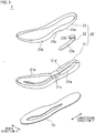
- FIG. 3 is an exploded perspective view of the shoe sole 1.
- the outer sole 10 includes a bottom surface portion, which comes into contact with a road surface, formed along the entire foot length in a longitudinal direction Y.
- the toe side is positioned higher than the heel side so that the motion of a foot from the landing to pushing off can be smoothly performed.
- the outer sole 10 is formed of a rubber material or the like, so as to absorb bumps and dips on a road surface and have abrasion resistance and durability.
- the midsole 20 is disposed on the outer sole 10 and formed along the entire foot length in a longitudinal direction Y.
- the midsole 20 includes a lower midsole 21, an upper midsole 23, and a cushion member 22.
- a rearfoot part 21a and a forefoot part 21b are continuously formed, and, in the midfoot portion, a recess 21c is provided such as to hole the rearfoot part 21a downward.
- the recess 21c forms an inner surface on the bottom side of the through hole part 40 illustrated in FIG. 1 , and an inner surface 23c on the upper side of the through hole part 40 is formed by the midfoot portion of the upper midsole 23.
- a groove 21d is provided such as to extend in a longitudinal direction from the rearfoot portion to the midfoot portion of the lower midsole 21.
- the cushion member 22 of a plate shape is disposed in a heel portion and includes a lateral cushion part 22a and a medial cushion part 22b.
- the hardness of the cushion member 22 is lower than that of the lower midsole 21 and the upper midsole 23.
- the lateral cushion part 22a is provided on the lateral side to extend from a rear part of the heel portion to the midfoot portion.
- the medial cushion part 22b is provided in the heel portion to extend from a rear part toward the medial side.
- the medial cushion part 22b has a smaller length dimension than the lateral cushion part 22a to restrain medial tilting of the heel.
- the medial cushion part 22b may have a length dimension similar to that of the lateral cushion part 22a and may be provided to extend toward the lateral side.
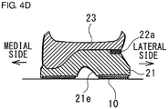
- FIG. 4A, 4B, 4C and 4D are sectional views of the heel portion, which each intersect a longitudinal direction.
- FIG. 4A illustrates a cross section of the heel portion of the shoe sole 1 according to the present embodiment
- FIGS. 4B, 4C , 4D and 4E illustrate modifications.
- the lateral cushion part 22a is shown on the cross section, as described previously.
- the cushion parts are equally provided on the medial side and the lateral side.
- the upper midsole 23 is made thicker on the medial side to restrain medial tilting of the ankle.
- the cushion member 22 is provided only on the lateral side. Also, a groove 21e, which corresponds to the groove 21d illustrated in FIG. 4A , is provided on the lower surface side of the lower midsole 21 and facilitates the joining between the lower midsole 21 and the upper midsole 23, so that the manufacturing process can be simplified.
- the upper midsole 23 includes a rearfoot part 23a and a forefoot part 23b, which respectively correspond to the rearfoot part 21a and the forefoot part 21b of the lower midsole 21.
- the upper midsole 23 is joined such that the bottom surfaces of the rearfoot part 23a and the forefoot part 23b are laminated on the upper surfaces of the rearfoot part 21a and the forefoot part 21b of the lower midsole 21.
- the cushion member 22 is provided in the heel portion between the lower midsole 21 and the upper midsole 23. In the state where the lower midsole 21 and the upper midsole 23 are laminated, the groove 21d of the lower midsole 21 penetrates rearward.
- the groove 21d of the lower midsole 21 continues to a through hole penetrating in a vertical direction, which is provided in a region from the midfoot portion to the forefoot portion of the lower midsole 21.
- the groove 21d also continues to a through hole formed in a middle part in a width direction of the outer sole 10.
- FIG. 5A is a side view that illustrates the lateral side of the shoe sole 1
- FIG. 5B is a vertical sectional view of the shoe sole, which includes the center line N shown in FIG. 2 .
- a rear bottom surface part 24 extending from the midfoot portion to the rearfoot portion is in contact with the virtual surface S.
- the rear bottom surface part 24 may be in contact with the virtual surface S entirely in a longitudinal direction, or may be partially spaced away from the virtual surface S, such as in a rear part of the heel portion.
- the portion to be in surface-contact of the rear bottom surface part 24 in the heel portion and the midfoot portion may preferably be provided in a range of 20% or greater of the entire length M of the shoe sole 1, and more preferably be provided in a range of 35% or greater thereof.
- the surface-contact when fine asperities are provided on the rear bottom surface part 24, a surface that passes through the lowermost surfaces of the asperities may be regarded as a virtual rear bottom surface part 24.
- a front bottom surface part 25 is provided to continue to the front part of the rear bottom surface part 24 and also extend to a toe portion 26 such as to be spaced away from the virtual surface S.
- the front bottom surface part 25 extends upward toward the front side and reaches the toe portion 26.
- the front bottom surface part 25 is formed only by a curved surface and a linear surface and does not include a portion extending downward toward the front side.
- the boundary between the rear bottom surface part 24 and the front bottom surface part 25 is positioned between the position of 50% of the entire length M of the shoe sole 1 from the front end and a point P0 corresponding to an MP joint (the entire length M is assumed to be identical with the entire length of the shoe 100, and the same applies hereinafter).
- the rear bottom surface part 24 and the front bottom surface part 25 form a bottom surface part 60.
- the point P0 corresponding to an MP joint may be a position corresponding to the thenar eminence on the upper surface of the midsole 20, as shown in FIG. 5B , or may be a position corresponding to the hypothenar eminence among the MP joints. In other words, P0 may be positioned within a range from 55% to 75% of the entire length M of the shoe sole 1 from the rear end.
- a height L3 of the toe portion 26 is defined as a height from the virtual surface to a point P3 at which an edge portion 26a, which is joined with the upper 9 in the upper surface of the midsole 20 (an inner-side surface of the shoe 100), extends upward, as illustrated in FIG. 5B .
- the height L3 of the toe portion 26 may also be defined as a height from the virtual surface to a point P4, which is the tip of the outer shape of the toe portion 26. In the following description, the height from the virtual surface to the point P3 is used as the height L3 of the toe portion 26.
- the thickness of the rear bottom surface part 24 side of the shoe sole 1 is considered based on one of a thickness L1 of the shoe sole 1 at a point P1 in the heel portion and a thickness L2 of the shoe sole 1 at a point P2 in the midfoot portion.
- the height L3 of the toe portion 26 is set to 170% or greater and 250% or less of the thickness L1 of the shoe sole 1 at the point P1 in the heel portion.
- the height L3 of the toe portion 26 is also set to 170% or greater and 250% or less of the thickness L1 of the shoe sole 1 at the point P2 in the midfoot portion.
- the position of the point P2 in the midfoot portion may be defined as a position in the thickest part within a range from about 30% to 40% of the entire length M of the shoe sole 1 from the rear end.
- the height L3 of the toe portion 26 is defined as the height at the point P4
- the height L3 is set to 150% or greater and 250% or less of the thickness L1 of the shoe sole 1 at the point P2 in the midfoot portion.
- the position of the point P1 in the heel portion may be defined as a position in the thickest part in the heel portion (a range from 15% to 30% of the entire length M of the shoe sole 1 from the rear end), and the thickness dimension of the shoe sole 1 at the point P1 may be set to 20 mm or greater, for example.
- the bending rigidity in an extension direction of the shoe sole 1 corresponding to an MP joint part, obtained by three-point bend testing, may be 20 N/mm or greater, for example.
- the difference between the thickness of the shoe sole 1 in the heel portion in a no-load state where a foot is not placed on the shoe sole 1 and the thickness of the shoe sole 1 at a position corresponding to the MP joint part may be set to 5 mm or less, for example.
- FIGS. 6A and 6B are schematic diagrams used to describe an upper surface part 61 of the shoe sole 1. Each of FIGS. 6A and 6B illustrates a sectional view similar to that in FIG. 5B .
- a first upper surface part 27 is formed to extend from the rearfoot portion to the midfoot portion and corresponds to a surface included in predetermined parallel conditions with respect to the virtual surface S in a no-load state.
- the surface included in predetermined parallel conditions means a surface positioned between a virtual plane SU1 and a virtual plane SU2.
- the virtual plane SU1 is the highest surface within a region that includes a front end of the first upper surface part 27 (front part), which will be described later, and a position of 15% of the entire length M of the shoe sole 1 from the rear end (rear part), and the virtual plane SU2 is the lowest surface in the region.
- the surface included in predetermined parallel conditions is also located within a region where the height difference between SU1 and SU2 is 12 mm or less and formed to be parallel with the virtual surface S or to incline downward from the rear part toward the front part.
- FIG. 6A illustrates the case where the first upper surface part 27 is parallel with the virtual surface S.
- the first upper surface part 27 formed to incline downward from the rear part to the front part with a height reduction amount of 5 mm.
- the first upper surface part 27 may be suitably flat with fewer asperities; however, the first upper surface part 27 may have some asperities, have a height difference in a width direction, or have a twist, for example.
- a second upper surface part 28 continues to the front end of the first upper surface part 27 and extends upward toward the front side to reach the toe portion 26.
- the second upper surface part 28 is formed only by a curved surface and a linear surface extending upward toward the front side and does not include a portion extending downward toward the front side. As illustrated in FIGS. 6A and 6B , the second upper surface part 28 is curved to be recessed with respect to the upper side.
- the boundary (front end) between the first upper surface part 27 and the second upper surface part 28 may be positioned within a range from 25% to 45% of the entire length M of the shoe sole 1 from the front end, for example.
- the upper surface of the midsole 20 in the shoe sole 1 has been described with reference to FIGS. 6A and 6B .
- an inner sole omitted in the drawings, is provided on the midsole 20
- the first upper surface part 27 and the second upper surface part 28 as described above may be defined in the upper surface of the inner sole.
- the outer sole 10 rubber, rubber foam, thermoplastic polyurethane (TPU), and thermoplastic and thermosetting elastomers may be used, for example.
- the lower midsole 21 may be formed of resin foam, for example.
- a resin a polyolefin resin, ethylene-vinyl acetate copolymer (EVA), or a styrene elastomer may be used, for example, and the resin may contain other arbitrary components, such as fiber, as appropriate.
- the cushion member 22 is formed into a gel state or the like using thermoplastic and thermosetting elastomers, for example.
- the cushion member 22 may be formed of a foam material such as to be hollow.
- the hardness of the outer sole 10 may be set to HA70, for example. Also, in the midsole 20, the hardness of the lower midsole 21 may be set to HC55, the hardness of the upper midsole 23 may be set to HC67, and the hardness of the cushion member 22 may be set to HC47, for example.
- FIG. 7 is a chart used to describe rotational motion of the ankle joint in a longitudinal direction.
- a column A in FIG. 7 shows a case where the bottom surface of the shoe sole 1 is almost flat, and the rotational motion of the ankle joint in a longitudinal direction is large.
- the body weight is shifted forward after the landing and the ankle joint is bent forward, so that an angle ⁇ ( ⁇ 2) at the ankle joint becomes smaller.
- Such rotational motion of the ankle joint causes stretch motion of muscles of the foot.
- the angle ⁇ ( ⁇ 3) at the ankle joint inversely becomes larger until the pushing off.
- a column B in FIG. 7 shows a case where the shoe sole 1 includes the front bottom surface part 25 described above, and the rotational motion of the ankle joint in a longitudinal direction is small.
- the shoe sole 1 when the body weight is shifted forward after the landing, the shoe sole 1 is rotated such that the front bottom surface part 25 comes into contact with a road surface. Accordingly, the forward rotational motion is restrained, so that the change of the angle ⁇ ( ⁇ 2) at the ankle joint is small. Thereafter, the change of the angle ⁇ ( ⁇ 3) at the ankle joint remains small until the pushing off.
- FIG. 8 is a graph as an example that shows energy consumption in the ankle joint.
- the horizontal axis represents time
- the vertical axis represents energy consumption in the ankle joint
- the energy consumption is compared between the cases of the columns A and B in FIG. 7 .
- energy consumption is generally a positive value, the case where muscles contract is indicated in the positive direction, and the case where muscles stretch is indicated in the negative direction, for the sake of convenience.
- the energy consumption at the time of landing is greater in the case of the shoe sole 1 in the column A, compared to the case of the shoe sole 1 in the column B.
- the energy consumption at the time of landing is reduced mainly by the cushion member 22 provided in the heel portion of the shoe sole 1.
- the rotational motion of the ankle joint ⁇ can be made smaller in the case of the column B compared to the case of the column A, as described with reference to FIG. 7 . Accordingly, the energy consumption becomes smaller in the case of the column B.
- the stability at the time of landing of a foot can be ensured in the shoe sole 1 of the shoe 100.
- the toe portion 26 is positioned higher than the rear bottom surface part 24, the rotational motion of the ankle joint in a longitudinal direction during walking and running is reduced and the energy consumption is restrained, so that strain on the foot can be alleviated.
- the height L3 of the toe portion 26 from the virtual surface S to 170% or greater with respect to the thickness dimension L1 of the rear bottom surface part 24 in the heel portion, the effect of reducing the energy consumption can be achieved.
- the height L3 of the toe portion 26 from the virtual surface S to 250% or less with respect to the thickness dimension L1 in the heel portion, the bending angle at the MP joint part of the foot can be maintained within a certain range.
- the height L3 of the toe portion 26 from the virtual surface S may be set to 170% or greater and 250% or less with respect to the thickness dimension L2 in the midfoot portion. In this case, it is considered that, at least after the landing of the midfoot portion, the strain on the ankle joint placed during the rotational motion toward the toe portion 26 in the shoe sole 1 can be alleviated.
- the first upper surface part 27 is formed as a surface included in predetermined parallel conditions, as described previously.
- the second upper surface part 28 is formed to continue to the front end of the first upper surface part 27 and extend upward toward the front side.
- the rear bottom surface part 24 includes a portion to be in surface-contact with the virtual surface S in the rearfoot portion and the midfoot portion, the stability at the time of landing of the rear bottom surface part 24 can be increased. Also, since the front bottom surface part 25 continues to the front part of the rear bottom surface part 24 and also curvedly extends to the toe portion 26, the rotational motion of the foot can be smoothly performed. In the front bottom surface part 25, by making a radius of curvature R1 in the rear part continuing to the rear bottom surface part smaller than a radius of curvature R2 in the toe portion, the rotational motion of the shoe sole 1 after the landing of the midfoot portion can be made to function more easily.
- the radius of curvature R1 smaller than the radius of curvature R2 may be positioned along the MP joint part from the medial side to the lateral side, for example.
- R1 is set to 85% or less of R2, the effect of smoother rotational motion can be obtained.
- the front bottom surface part 25 includes, within the region thereof, the point P0 facing the MP joint part of a foot. Accordingly, while the rotational motion of the shoe sole 1 proceeds after the landing of the midfoot portion until the landing of the toe portion 26, the motion of the MP joint part of the foot is made smaller. With such smaller motion of the MP joint part of the foot, energy consumption in the MP joint part is reduced, and the strain caused by stretching and contraction in the MP joint part can be alleviated.
- the upper midsole 23 has higher hardness than the lower midsole 21 and functions as a deformation restraining part for restraining deformation of the shoe sole 1 or the foot, thereby maintaining a constant foot shape more easily.
- a deformation restraining part may be formed to cross at least a portion of each of the rear bottom surface part 24 and the front bottom surface part 25.
- the deformation restraining part may be replaced by a plate member, omitted in the drawings, having relatively high hardness, for example.
- the lower midsole 21 has lower hardness than the upper midsole 23 and functions as a deformation allowance part in the shoe sole 1 for absorbing impact at the time of landing or bumps and dips on a road surface.
- the through hole part 40 provided in the midsole 20 reduces upthrusts from bumps and dips on a road surface in the midfoot portion and functions as a deformation allowance part similarly to the lower midsole 21.
- the cushion member 22 also reduces impact at the time of landing and upthrusts from bumps and dips on a road surface in the rearfoot portion and functions as a deformation allowance part similarly to the lower midsole 21.
- a ratio of the thickness dimension of the upper midsole 23 with respect to the thickness dimension of the lower midsole 21 in the forefoot portion and the front part from a middle part in the midfoot portion is larger than that in the rearfoot portion and the rear part of the midfoot portion. Accordingly, in a region from a middle part of the midfoot portion to the toe portion 26 of the shoe sole 1, the effect of restraining the deformation of the shoe sole 1 is higher.
- the bending rigidity at the time of bending a material of a plate shape is generally determined based on the Young's modulus and the second moment of area of the material. If the material physical properties, including hardness, are the same and the width is also the same, the bending rigidity is proportional to the cube of the material thickness. Accordingly, when the shoe sole 1 is made thinner, the material physical properties need to be supplemented by insertion of a high-strength member, such as a carbon fiber reinforced plastic, or increase of hardness of the outer sole 10, for example.
- the outer sole 10 also functions as a deformation restraining part.
- the toe portion 26 of the shoe sole 1 extends upward such that the height of the toe portion 26 is 150% or greater of the thickness dimension L1 of the shoe sole 1 in the heel portion or the thickness dimension L2 of the shoe sole 1 in the midfoot portion (at a position of 30% of the entire length M from the rear end, for example) and when the bending rigidity in a longer axis direction in the forefoot portion of the shoe sole 1 (the rigidity at a position corresponding to the MP joint part) is three or more times larger than the rigidity of general running shoes (3 N/mm as a reference value), the deformation of the shoe sole 1 is restrained, and the effect of alleviating strain on the ankle joint can achieved.
- FIG. 9 is a perspective view that illustrates an external view of a shoe sole 1 according to a second embodiment
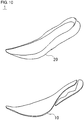
- FIG. 10 is an exploded perspective view of the shoe sole 1.
- the upper 9 as illustrated in FIG. 1 is joined such as to configure a shoe.
- the shoe sole 1 according to the second embodiment also includes the outer sole 10 and the midsole 20.
- the midsole 20 is not divided between the lower midsole and the upper midsole and is integrally formed.
- a tip part 10a of the toe portion 26 of the outer sole 10 is curled up along the upper 9.
- the material, shape, and the like of the midsole 20 of the shoe sole 1 may be determined so that, while the shoe sole 1 has cushioning properties, the bending rigidity of the shoe sole 1 is ensured, for example.
- the midsole 20 may be set between the hardness of the lower midsole 21 (HC55) and the hardness of the upper midsole 23 (HC67) described in the first embodiment, for example.
- the relationships among the thickness dimension L1 in the heel portion, the thickness dimension L2 in the midfoot portion, and the height L3 in the toe portion 26 from the virtual surface S in the shoe sole 1 according to the second embodiment are identical with those described in the first embodiment based on FIGS. 5A and 5B .
- the rear bottom surface part 24, the front bottom surface part 25, the first upper surface part 27, the second upper surface part 28, and the like are also identical with those described in the first embodiment based on FIGS. 6A and 6B .
- the toe portion 26 in the shoe sole 1 is provided at a high position, so that the rotational motion of the ankle joint is restrained and the energy consumption is reduced, thereby alleviating strain on the foot, as is the case in the first embodiment.
- the rear bottom surface part 24, the front bottom surface part 25, the first upper surface part 27, the second upper surface part 28, and the like function similarly to those in the first embodiment.
- a cushion material or the like may be provided as appropriate.
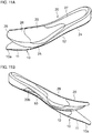
- FIG. 11A is a perspective view that illustrates an external view of a shoe sole 1 according to a third embodiment viewed from the lateral side
- FIG. 11B is a perspective view that illustrates an external view of the shoe sole 1 according to the third embodiment viewed from the medial side
- FIG. 12 is an exploded perspective view of the shoe sole 1.
- the upper 9 as illustrated in FIG. 1 is joined such as to configure a shoe.
- the shoe sole 1 according to the third embodiment also includes the outer sole 10 and the midsole 20, and a plate member 50 is further provided between the outer sole 10 and the midsole 20.
- the outer sole 10 includes a toe sole part 11 disposed in a toe part, and a sole main body 12 that continues to the rear part of the toe sole part 11.
- the tip part 10a of the toe portion 26 of the outer sole 10 is curled up along the upper 9.
- a recess 20a (see FIG. 12 ) is formed such as to hole the upper surface.
- a cushion member 29 having a shape corresponding to the recess 20a is fitted into the recess 20a.
- the cushion member 29 extends along the entire width in a width direction X to correspond to the MP joints Ja of a foot and also extends rearward on the lateral side.
- the shoe sole 1 may be configured not to include the recess 20a and the cushion member 29, and a portion corresponding to the cushion member 29 may be made of the same material as the midsole 20 and integrally formed.
- FIG. 13 is a sectional view, intersecting a longitudinal direction, of the shoe sole 1 including the cutout part 20b.
- the bottom side of the cutout part 20b is closed by the plate member 50 disposed along the lower surface of the midsole 20.
- the inner side of the cutout part 20b is closed at a middle part in a width direction X.
- a vent hole 20c is formed to pierce through the midsole 20 from the upper inner surface of the cutout part 20b toward the upper side, thereby allowing air to pass through the inside of the shoe easily.
- the plate member 50 is formed of a material having higher rigidity than the other portions of the shoe sole. Also, the plate member 50 has a thin plate shape of which the outer dimension in a width direction X is larger in the midfoot portion and extends to be narrower toward the forefoot portion and the rearfoot portion.
- the plate member 50 illustrated in FIG. 12 has a shape that includes through holes vertically piercing in the midfoot portion; however, the plate member 50 may have a shape that does not include the through holes.
- thermoplastic resin such as thermoplastic polyurethane (TPU)
- TPU thermoplastic polyurethane
- the midsole 20 may be formed of resin foam, for example.
- a thermoplastic resin such as a polyolefin resin and ethylene-vinyl acetate copolymer (EVA)
- EVA ethylene-vinyl acetate copolymer
- the cushion member 29 may be formed of resin foam, for example.
- a foamed body using a polyolefin resin, EVA, or a styrene elastomer may be used, for example.
- a glass fiber reinforced plastic or other fiber reinforced plastics may be used, and thermoplastic and thermosetting elastomers may also be used.
- the hardness of the toe sole part 11 may be set to HA62, and the hardness of the sole main body 12 may be set to HA70, for example.
- the hardness of the midsole 20 may be set to HC57, and the hardness of the cushion member 29 may be set to HC50, for example.
- the plate member 50 high rigidity is ensured by setting the elastic modulus to 2.87 GPa, for example, and the hardness of the plate member 50 is set higher than that of the midsole 20.
- the relationships among the thickness dimension L1 in the heel portion, the thickness dimension L2 in the midfoot portion, and the height L3 in the toe portion 26 from the virtual surface S in the shoe sole 1 according to the third embodiment are identical with those described in the first embodiment based on FIGS. 5A and 5B .
- the rear bottom surface part 24, the front bottom surface part 25, the first upper surface part 27, the second upper surface part 28, and the like are also identical with those described in the first embodiment based on FIGS. 6A and 6B .
- the toe portion 26 in the shoe sole 1 is provided at a high position, so that the rotational motion of the ankle joint is restrained and the energy consumption is reduced, thereby alleviating strain on the foot, as is the case in the first embodiment.
- the rear bottom surface part 24, the front bottom surface part 25, the first upper surface part 27, the second upper surface part 28, and the like function similarly to those in the first embodiment.
- the hardness of the midsole 20 may be set to HC57 as described above, for example, which is similar to the hardness of the lower midsole 21 in the first embodiment (HC55). Accordingly, the bending rigidity of the midsole 20 becomes lower.
- the plate member 50 provided between the midsole 20 and the outer sole 10 supplements the bending rigidity of the midsole 20 and functions as a deformation restraining part for restraining deformation of the shoe sole 1. With the plate member 50 provided, the bending deformation of the shoe sole 1 is reduced and the rotational motion of the ankle joint is restrained, so that the strain on the foot can be alleviated.
- the hardness of the midsole 20 is set to a value similar to the hardness of the lower midsole 21 in the first embodiment, thereby restraining impact at the time of landing and upthrusts from bumps and dips on a road surface.
- Providing the cushion member 29 in the shoe sole 1 also restrains impact at the time of landing and upthrusts from bumps and dips on a road surface.
- the cutout part 20b provided in the midsole 20 reduces lowering of the medial longitudinal arch of a foot.
- lowering of the medial longitudinal arch of the foot sometimes occurs.
- the midsole 20 is deformed such as to lift up on the medial side of the midfoot portion, so that lowering of the medial longitudinal arch of the foot can be reduced.
- the vent hole 20c is provided to pierce through the midsole 20 from the upper inner surface of the cutout part 20b toward the upper side, thereby restraining entry of water into the shoe. Also, since the vent hole 20c is provided in a middle part in a width direction of the cutout part 20b, a space of the cutout part 20b is located below the vent hole 20c. Accordingly, water entering the vent hole 20c drops into the space, so that entry of water into the shoe can be restrained.
- FIG. 14 is a perspective view that illustrates an external view of a shoe sole 1 according to a modification viewed from a bottom portion side.
- the recess 13 is formed on the lateral side of the midfoot portion of the rear bottom surface part 24 such as to hole the bottom surface toward the upper side.
- the recess 13 restrains upthrusts from bumps and dips on a road surface in the midfoot portion.
- the recess 13 need not necessarily be provided on the bottom surface of the shoe sole 1.
- the recess 13 is provided on the lateral side of the midfoot portion; however, the recess 13 may be provided on the medial side of the midfoot portion, as indicated by a dashed dotted line, or may be provided on each of the lateral side and the medial side. Also, the recess 13 may be provided along the entire width from the medial side to the lateral side in the midfoot portion. When the recess 13 is provided, the height from the virtual surface S to the upper surface of the midsole 20 may be used as a substitute for the thickness dimension L2 of the shoe sole 1 in the midfoot portion described with reference to FIG. 5B .
- the shoe sole 1 includes the rear bottom surface part 24 and the toe portion 26.
- the rear bottom surface part 24 is formed to extend from the rearfoot portion to the midfoot portion and, when the shoe sole is placed on a flat virtual surface S, the rear bottom surface part 24 is in contact with the virtual surface S.
- the height L3 of the toe portion 26 from the virtual surface S is set to 170% or greater and 250% or less with respect to a thickness dimension in the rear bottom surface part 24. Accordingly, the shoe sole 1 can ensure stability of landing of the rear bottom surface part 24 and also alleviate strain on the ankle joint during forward walking and running.
- the shoe sole 1 also includes the first upper surface part 27 and the second upper surface part 28.
- the first upper surface part 27 is formed to extend from the rearfoot portion to the midfoot portion and is formed as a surface included in predetermined parallel conditions, as described previously.
- the second upper surface part 28 continues to the front end of the first upper surface part 27 and extends upward toward the front side to reach the toe portion 26. Accordingly, in the shoe sole 1, since the downward inclination of the first upper surface part 27 toward the front side is maintained within a certain range, the upward inclination of the second upper surface part 28 toward the front side can be made gentle, so that excessive upward bending of the toe can be restrained.
- a dimension in the heel portion (the thickness dimension L1) is used. Accordingly, in the shoe sole 1, the height L3 of the toe portion 26 from the virtual surface S is set based on the thickness of the heel portion, so that, after the landing of the heel portion, the strain on the ankle joint placed during the rotational motion toward the toe portion can be alleviated.
- a dimension in the midfoot portion (the thickness dimension L2) is also used. Accordingly, in the shoe sole 1, the height L3 of the toe portion 26 from the virtual surface S is set based on the thickness of the midfoot portion, so that, at least after the landing of the midfoot portion, the strain on the ankle joint placed during the rotational motion toward the toe portion can be alleviated.
- the rear bottom surface part 24 includes a portion to be in surface-contact with the virtual surface S, in a range of 20% or greater of the entire shoe sole in the rearfoot portion and the midfoot portion. This increases stability at the time of landing of the rear bottom surface part 24 in the shoe sole 1.
- the shoe sole 1 also includes the front bottom surface part 25 that continues to the front part of the rear bottom surface part 24 and also curvedly extends to the toe portion 26 such as to be spaced away from the virtual surface. This can make the rotational motion of a foot smoother in the shoe sole 1.
- the radius of curvature R1 in the rear part continuing to the rear bottom surface part 24 is smaller than the radius of curvature R2 in a middle part continuing to the rear part. Accordingly, in the shoe sole 1, the rotational motion of the shoe sole 1 after the landing of the midfoot portion can be made to function more easily.
- the front bottom surface part 25 includes a portion (point P0) facing the MP joint part of a foot. Accordingly, in the shoe sole 1, while the rotational motion of the shoe sole 1 proceeds until the landing of the toe portion 26, the motion of the MP joint part of the foot is made smaller.
- the shoe sole 1 also includes the upper midsole 23 as a deformation restraining part formed to cross at least a portion of each of the rear bottom surface part 24 and the front bottom surface part 25. Accordingly, with the shoe sole 1, a constant foot shape can be maintained more easily.
- the shoe sole 1 also includes the lower midsole 21 as a deformation allowance part formed beneath the upper midsole 23. Accordingly, in the shoe sole 1, impact at the time of landing and a change in a road surface can be absorbed in the deformation allowance part.
- the lower midsole 21 as the deformation allowance part extends from the rearfoot portion to the toe portion 26, and has lower hardness than the upper midsole 23 as the deformation restraining part. This makes the shoe sole 1 to have cushioning properties in the region from the rearfoot portion to the toe.
- the deformation allowance part may include the through hole part 40 that is provided in the midfoot portion and that penetrates in a width direction. Accordingly, in the shoe sole 1, upthrusts from bumps and dips on a road surface in the midfoot portion can be restrained.
- the deformation allowance part may also include the cushion member 22 disposed in the rearfoot portion. This makes the shoe sole 1 to have cushioning properties in the rearfoot portion.
- the deformation restraining part may be constituted by the plate member 50. Accordingly, in the shoe sole 1, while a constant foot shape is maintained by means of the plate member 50, the other midsole portions can be made to have cushioning properties.
- the shoe 100 includes the shoe sole 1 as described above, and the upper 9 disposed on the shoe sole 1. Accordingly, the shoe 100 can ensure stability of landing of the rear bottom surface part 24 and also alleviate strain on the ankle joint during forward walking and running.
- the present invention relates to a shoe.
Landscapes
- Health & Medical Sciences (AREA)
- Epidemiology (AREA)
- General Health & Medical Sciences (AREA)
- Public Health (AREA)
- Chemical & Material Sciences (AREA)
- Engineering & Computer Science (AREA)
- Materials Engineering (AREA)
- Footwear And Its Accessory, Manufacturing Method And Apparatuses (AREA)
Abstract

Description
- The present invention relates to shoe soles and shoes used for sports or the like.
- Shoes used for sports or the like are desired to follow the motion of foot portions of the wearer and firmly support the feet during walking, running, or exercising, for example, and also to reduce fatigue of the feet.
- For example,
Patent Literature 1 discloses a shoe sole that includes a curved portion extending between an anterior-most point disposed in a forefoot region and a posterior-most point disposed closer to a heel region than the anterior-most point. The curved portion has a constant radius of curvature in a region from the anterior-most point to a metatarsophalangeal point (MP point). - Patent Literature 1: Japanese Translation of PCT International Application Publication No.
2018-529461 - In
Patent Literature 1, the shoe sole of the forefoot region is curved to reduce the length of the lever arm about the ankle, thereby alleviating strain on the ankle joint; however, dissipation of energy caused by the motion of the ankle joint itself is not considered. With regard to the dissipation of energy caused by the motion of the ankle joint itself, the inventors have obtained the following findings. - The magnitude of the motion of the ankle joint bending forward varies according to the relative height positions of the heel and the toe. For example, in a situation where a person walks or runs forward, when the heights of the heel and the toe are almost the same, the motion of the ankle joint accompanying the forward shift of the center of gravity becomes larger before rotational motion of the foot starts, so that the strain due to the dissipation of energy caused by the motion of the ankle joint itself is increased. In the shoe sole described in
Patent Literature 1, the thickness of the shoe sole in the heel portion, i.e., the height of the heel portion, is almost the same as the height of the toe, as illustrated inFIG. 3 ofPatent Literature 1 for example, and the motion of the ankle joint bending forward is not considered. - The present invention has been made in view of such an issue, and a purpose thereof is to provide a shoe sole and a shoe that can restrain the motion of the ankle joint and reduce the strain.
- An aspect of the present invention relates to a shoe sole. The shoe sole includes: a rear bottom surface part formed to extend from a rearfoot portion to a midfoot portion and to be, when the shoe sole is placed on a virtual surface as a flat surface, in contact with the virtual surface; and a toe portion of which a height from the virtual surface is set to 170% or greater and 250% or less with respect to a thickness dimension in the rear bottom surface part.
- Another aspect of the present invention relates to a shoe. The shoe includes the shoe sole as described above, and an upper disposed on the shoe sole.
- Optional combinations of the aforementioned constituting elements, and implementation of the present invention, including the constituting elements and expressions, in the form of methods or apparatuses may also be practiced as additional modes of the present invention.
- The present invention can restrain the motion of the ankle joint and reduce the strain.
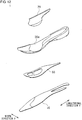
- Embodiments will now be described, by way of example only, with reference to the accompanying drawings which are meant to be exemplary, not limiting, and wherein like elements are numbered alike in several Figures, in which:
-
FIG. 1 is an exploded perspective view that illustrates an external view of a shoe according to a first embodiment; -
FIG. 2 is a schematic diagram in which a skeleton model of a human foot is superimposed upon a plan view of a shoe sole; -
FIG. 3 is an exploded perspective view of the shoe sole; -
FIGS. 4A, 4B, 4C and4D are sectional views of a heel portion, which each intersect a longitudinal direction; -
FIG. 5A is a side view that illustrates a lateral side of the shoe sole, andFIG. 5B is a vertical sectional view of the shoe sole, which includes a center line N shown inFIG. 2 ; -
FIGS. 6A and 6B are schematic diagrams used to describe an upper surface of the shoe sole; -
FIG. 7 is a chart used to describe rotational motion of the ankle joint in a longitudinal direction; -
FIG. 8 is a graph as an example that shows energy consumption in the ankle joint; -
FIG. 9 is a perspective view that illustrates an external view of a shoe sole according to a second embodiment; -
FIG. 10 is an exploded perspective view of the shoe sole; -
FIG. 11A is a perspective view that illustrates an external view of a shoe sole according to a third embodiment viewed from the lateral side, andFIG. 11B is a perspective view that illustrates an external view of the shoe sole according to the third embodiment viewed from the medial side; -
FIG. 12 is an exploded perspective view of the shoe sole; -
FIG. 13 is a sectional view, intersecting a longitudinal direction, of the shoe sole including a cutout part; and -
FIG. 14 is a perspective view that illustrates an external view of a shoe sole according to a modification viewed from a bottom portion side. - In the following, the present invention will be described based on preferred embodiments with reference to
FIGS. 1 through 14 . Like reference characters denote like or corresponding constituting elements and members in each drawing, and repetitive description will be omitted as appropriate. Also, the dimensions of a member may be appropriately enlarged or reduced in each drawing in order to facilitate understanding. Further, in each drawing, part of a member less relevant in describing embodiments may be omitted. -
FIG. 1 is an exploded perspective view that illustrates an external view of a shoe 100 according to a first embodiment. The shoe 100 includes an upper 9 and ashoe sole 1. The upper 9 is bonded to or sewed onto a circumferential edge part of theshoe sole 1 to cover the upper side of a foot. Theshoe sole 1 includes anouter sole 10 and amidsole 20, for example, and is configured by laminating themidsole 20 on theouter sole 10 and further laminating an insole or the like thereon, which is not illustrated. In themidsole 20, athrough hole part 40 penetrating in a width direction is formed. -
FIG. 2 is a schematic diagram in which a skeleton model of a human foot is superimposed upon a plan view of theshoe sole 1. A human foot is mainly constituted by cuneiform bones Ba, a cuboid bone Bb, a navicular bone Bc, a talus Bd, a calcaneus Be, metatarsal bones Bf, and phalanges Bg. Joints of a foot include MP joints Ja, Lisfranc joints Jb, and a Chopart's joint Jc. The Chopart's joint Jc includes a calcaneocuboid joint Jc1 formed by the cuboid bone Bb and the calcaneus Be, and a talocalcaneonavicular joint Jc2 formed by the navicular bone Bc and the talus Bd. - In the present invention, a center line N of a foot is represented by a straight line connecting a midpoint N3 between the center N1 of the thenar eminence and the center N2 of the hypothenar eminence, and the center N4 of the heel. For example, a longitudinal direction Y is in parallel with the center line N, and a width direction X is perpendicular to the center line N. A line P represents a straight line that extends along a width direction X, which is a direction perpendicular to the center line N, and that is assumed to pass through the heel-side end of the MP joints Ja. Also, a line Q represents a straight line that extends along a width direction X and that is assumed to pass through the toe-side end of the Chopart's joint Jc of the wearer. Hereinafter, a region from the line P to the toe is referred to as a forefoot portion, a region from the line P to the line Q is referred to as a midfoot portion, and a region from the line Q to the heel is referred to as a rearfoot portion. With regard to the relationship between the lines P, Q and the shoe 100, the line P is positioned within a range from 40% to 75% of the entire length M of the shoe 100 from the rear end on the heel side in a direction along the center line N, for example. More preferably, the line P is positioned within a range from 55% to 70% from the rear end. Also, the line Q is positioned within a range from 20% to 45% of the entire length M of the shoe 100 from the rear end on the heel side in a direction along the center line N. More preferably, the line Q is positioned within a range from 25% to 40% from the rear end.
-
FIG. 3 is an exploded perspective view of theshoe sole 1. The outer sole 10 includes a bottom surface portion, which comes into contact with a road surface, formed along the entire foot length in a longitudinal direction Y. The toe side is positioned higher than the heel side so that the motion of a foot from the landing to pushing off can be smoothly performed. The outer sole 10 is formed of a rubber material or the like, so as to absorb bumps and dips on a road surface and have abrasion resistance and durability. - The
midsole 20 is disposed on the outer sole 10 and formed along the entire foot length in a longitudinal direction Y. Themidsole 20 includes alower midsole 21, anupper midsole 23, and acushion member 22. In thelower midsole 21, arearfoot part 21a and aforefoot part 21b are continuously formed, and, in the midfoot portion, arecess 21c is provided such as to hole therearfoot part 21a downward. Therecess 21c forms an inner surface on the bottom side of the throughhole part 40 illustrated inFIG. 1 , and aninner surface 23c on the upper side of the throughhole part 40 is formed by the midfoot portion of theupper midsole 23. Also, agroove 21d is provided such as to extend in a longitudinal direction from the rearfoot portion to the midfoot portion of thelower midsole 21. - The
cushion member 22 of a plate shape is disposed in a heel portion and includes alateral cushion part 22a and amedial cushion part 22b. The hardness of thecushion member 22 is lower than that of thelower midsole 21 and theupper midsole 23. Thelateral cushion part 22a is provided on the lateral side to extend from a rear part of the heel portion to the midfoot portion. Themedial cushion part 22b is provided in the heel portion to extend from a rear part toward the medial side. Themedial cushion part 22b has a smaller length dimension than thelateral cushion part 22a to restrain medial tilting of the heel. However, themedial cushion part 22b may have a length dimension similar to that of thelateral cushion part 22a and may be provided to extend toward the lateral side.FIGS. 4A, 4B, 4C and4D are sectional views of the heel portion, which each intersect a longitudinal direction.FIG. 4A illustrates a cross section of the heel portion of the shoe sole 1 according to the present embodiment, andFIGS. 4B, 4C ,4D and4E illustrate modifications. In the heel portion of the present embodiment illustrated inFIG. 4A , thelateral cushion part 22a is shown on the cross section, as described previously. In the modification illustrated inFIG. 4B , the cushion parts are equally provided on the medial side and the lateral side. In the modification illustrated inFIG. 4C , theupper midsole 23 is made thicker on the medial side to restrain medial tilting of the ankle. In the modification illustrated inFIG. 4D , thecushion member 22 is provided only on the lateral side. Also, agroove 21e, which corresponds to thegroove 21d illustrated inFIG. 4A , is provided on the lower surface side of thelower midsole 21 and facilitates the joining between thelower midsole 21 and theupper midsole 23, so that the manufacturing process can be simplified. - The
upper midsole 23 includes arearfoot part 23a and aforefoot part 23b, which respectively correspond to therearfoot part 21a and theforefoot part 21b of thelower midsole 21. Theupper midsole 23 is joined such that the bottom surfaces of therearfoot part 23a and theforefoot part 23b are laminated on the upper surfaces of therearfoot part 21a and theforefoot part 21b of thelower midsole 21. Thecushion member 22 is provided in the heel portion between thelower midsole 21 and theupper midsole 23. In the state where thelower midsole 21 and theupper midsole 23 are laminated, thegroove 21d of thelower midsole 21 penetrates rearward. Toward the front, thegroove 21d of thelower midsole 21 continues to a through hole penetrating in a vertical direction, which is provided in a region from the midfoot portion to the forefoot portion of thelower midsole 21. Thegroove 21d also continues to a through hole formed in a middle part in a width direction of the outer sole 10. -
FIG. 5A is a side view that illustrates the lateral side of theshoe sole 1, andFIG. 5B is a vertical sectional view of the shoe sole, which includes the center line N shown inFIG. 2 . When theshoe sole 1 is placed on a flat virtual surface S, such as a ground surface, a rearbottom surface part 24 extending from the midfoot portion to the rearfoot portion is in contact with the virtual surface S. The rearbottom surface part 24 may be in contact with the virtual surface S entirely in a longitudinal direction, or may be partially spaced away from the virtual surface S, such as in a rear part of the heel portion. To improve the stability in a region from the heel portion to the midfoot portion at the time of landing, the portion to be in surface-contact of the rearbottom surface part 24 in the heel portion and the midfoot portion may preferably be provided in a range of 20% or greater of the entire length M of theshoe sole 1, and more preferably be provided in a range of 35% or greater thereof. With regard to the surface-contact, when fine asperities are provided on the rearbottom surface part 24, a surface that passes through the lowermost surfaces of the asperities may be regarded as a virtual rearbottom surface part 24. - A front
bottom surface part 25 is provided to continue to the front part of the rearbottom surface part 24 and also extend to atoe portion 26 such as to be spaced away from the virtual surface S. The frontbottom surface part 25 extends upward toward the front side and reaches thetoe portion 26. The frontbottom surface part 25 is formed only by a curved surface and a linear surface and does not include a portion extending downward toward the front side. The boundary between the rearbottom surface part 24 and the frontbottom surface part 25 is positioned between the position of 50% of the entire length M of the shoe sole 1 from the front end and a point P0 corresponding to an MP joint (the entire length M is assumed to be identical with the entire length of the shoe 100, and the same applies hereinafter). The rearbottom surface part 24 and the frontbottom surface part 25 form abottom surface part 60. The point P0 corresponding to an MP joint may be a position corresponding to the thenar eminence on the upper surface of themidsole 20, as shown inFIG. 5B , or may be a position corresponding to the hypothenar eminence among the MP joints. In other words, P0 may be positioned within a range from 55% to 75% of the entire length M of the shoe sole 1 from the rear end. - A height L3 of the
toe portion 26 is defined as a height from the virtual surface to a point P3 at which anedge portion 26a, which is joined with the upper 9 in the upper surface of the midsole 20 (an inner-side surface of the shoe 100), extends upward, as illustrated inFIG. 5B . The height L3 of thetoe portion 26 may also be defined as a height from the virtual surface to a point P4, which is the tip of the outer shape of thetoe portion 26. In the following description, the height from the virtual surface to the point P3 is used as the height L3 of thetoe portion 26. - The thickness of the rear
bottom surface part 24 side of theshoe sole 1 is considered based on one of a thickness L1 of the shoe sole 1 at a point P1 in the heel portion and a thickness L2 of the shoe sole 1 at a point P2 in the midfoot portion. The height L3 of thetoe portion 26 is set to 170% or greater and 250% or less of the thickness L1 of the shoe sole 1 at the point P1 in the heel portion. The height L3 of thetoe portion 26 is also set to 170% or greater and 250% or less of the thickness L1 of the shoe sole 1 at the point P2 in the midfoot portion. The position of the point P2 in the midfoot portion may be defined as a position in the thickest part within a range from about 30% to 40% of the entire length M of the shoe sole 1 from the rear end. When the height L3 of thetoe portion 26 is defined as the height at the point P4, the height L3 is set to 150% or greater and 250% or less of the thickness L1 of the shoe sole 1 at the point P2 in the midfoot portion. - The position of the point P1 in the heel portion may be defined as a position in the thickest part in the heel portion (a range from 15% to 30% of the entire length M of the shoe sole 1 from the rear end), and the thickness dimension of the shoe sole 1 at the point P1 may be set to 20 mm or greater, for example. The bending rigidity in an extension direction of the shoe sole 1 corresponding to an MP joint part, obtained by three-point bend testing, may be 20 N/mm or greater, for example. In the three-point bend testing, a 8-centimeter length in a longitudinal direction that crosses the MP joint part is supported at the both ends, a middle part between the both ends is pressed downward to obtain the relationship between the displacement and the load, and the slope of the displacement-load curve in a range of the displacement of 5 to 6 mm is obtained. Also, the difference between the thickness of the shoe sole 1 in the heel portion in a no-load state where a foot is not placed on the
shoe sole 1 and the thickness of the shoe sole 1 at a position corresponding to the MP joint part may be set to 5 mm or less, for example. -
FIGS. 6A and 6B are schematic diagrams used to describe anupper surface part 61 of theshoe sole 1. Each ofFIGS. 6A and 6B illustrates a sectional view similar to that inFIG. 5B . A firstupper surface part 27 is formed to extend from the rearfoot portion to the midfoot portion and corresponds to a surface included in predetermined parallel conditions with respect to the virtual surface S in a no-load state. The surface included in predetermined parallel conditions means a surface positioned between a virtual plane SU1 and a virtual plane SU2. The virtual plane SU1 is the highest surface within a region that includes a front end of the first upper surface part 27 (front part), which will be described later, and a position of 15% of the entire length M of the shoe sole 1 from the rear end (rear part), and the virtual plane SU2 is the lowest surface in the region. The surface included in predetermined parallel conditions is also located within a region where the height difference between SU1 and SU2 is 12 mm or less and formed to be parallel with the virtual surface S or to incline downward from the rear part toward the front part.FIG. 6A illustrates the case where the firstupper surface part 27 is parallel with the virtual surface S.FIG. 6B illustrates the firstupper surface part 27 formed to incline downward from the rear part to the front part with a height reduction amount of 5 mm. For less incongruity on the bottom of a foot, the firstupper surface part 27 may be suitably flat with fewer asperities; however, the firstupper surface part 27 may have some asperities, have a height difference in a width direction, or have a twist, for example. - A second
upper surface part 28 continues to the front end of the firstupper surface part 27 and extends upward toward the front side to reach thetoe portion 26. The secondupper surface part 28 is formed only by a curved surface and a linear surface extending upward toward the front side and does not include a portion extending downward toward the front side. As illustrated inFIGS. 6A and 6B , the secondupper surface part 28 is curved to be recessed with respect to the upper side. The boundary (front end) between the firstupper surface part 27 and the secondupper surface part 28 may be positioned within a range from 25% to 45% of the entire length M of the shoe sole 1 from the front end, for example. - The upper surface of the
midsole 20 in theshoe sole 1 has been described with reference toFIGS. 6A and 6B . However, when an inner sole, omitted in the drawings, is provided on themidsole 20, the firstupper surface part 27 and the secondupper surface part 28 as described above may be defined in the upper surface of the inner sole. - For the outer sole 10, rubber, rubber foam, thermoplastic polyurethane (TPU), and thermoplastic and thermosetting elastomers may be used, for example. In the
midsole 20, thelower midsole 21 may be formed of resin foam, for example. As a resin, a polyolefin resin, ethylene-vinyl acetate copolymer (EVA), or a styrene elastomer may be used, for example, and the resin may contain other arbitrary components, such as fiber, as appropriate. For theupper midsole 23, resin foam using a polyolefin resin, EVA, or a styrene elastomer may be used, for example, and the resin foam may contain other arbitrary components, such as cellulose nanofiber or other fiber, as appropriate. Thecushion member 22 is formed into a gel state or the like using thermoplastic and thermosetting elastomers, for example. Alternatively, as with themidsole 20, thecushion member 22 may be formed of a foam material such as to be hollow. - The hardness of the outer sole 10 may be set to HA70, for example. Also, in the
midsole 20, the hardness of thelower midsole 21 may be set to HC55, the hardness of theupper midsole 23 may be set to HC67, and the hardness of thecushion member 22 may be set to HC47, for example. - There will now be described the functions of the shoe 100.
FIG. 7 is a chart used to describe rotational motion of the ankle joint in a longitudinal direction. A column A inFIG. 7 shows a case where the bottom surface of theshoe sole 1 is almost flat, and the rotational motion of the ankle joint in a longitudinal direction is large. In the column A, the body weight is shifted forward after the landing and the ankle joint is bent forward, so that an angle α (α2) at the ankle joint becomes smaller. Such rotational motion of the ankle joint causes stretch motion of muscles of the foot. Thereafter, the angle α (α3) at the ankle joint inversely becomes larger until the pushing off. - Meanwhile, a column B in
FIG. 7 shows a case where theshoe sole 1 includes the frontbottom surface part 25 described above, and the rotational motion of the ankle joint in a longitudinal direction is small. In the column B, when the body weight is shifted forward after the landing, theshoe sole 1 is rotated such that the frontbottom surface part 25 comes into contact with a road surface. Accordingly, the forward rotational motion is restrained, so that the change of the angle α (α2) at the ankle joint is small. Thereafter, the change of the angle α (α3) at the ankle joint remains small until the pushing off. -
FIG. 8 is a graph as an example that shows energy consumption in the ankle joint. InFIG. 8 , the horizontal axis represents time, and the vertical axis represents energy consumption in the ankle joint, and the energy consumption is compared between the cases of the columns A and B inFIG. 7 . Although energy consumption is generally a positive value, the case where muscles contract is indicated in the positive direction, and the case where muscles stretch is indicated in the negative direction, for the sake of convenience. - The energy consumption at the time of landing is greater in the case of the shoe sole 1 in the column A, compared to the case of the shoe sole 1 in the column B. The energy consumption at the time of landing is reduced mainly by the
cushion member 22 provided in the heel portion of theshoe sole 1. Until the pushing off after the landing, the rotational motion of the ankle joint α can be made smaller in the case of the column B compared to the case of the column A, as described with reference toFIG. 7 . Accordingly, the energy consumption becomes smaller in the case of the column B. - With the rear
bottom surface part 24 provided, the stability at the time of landing of a foot can be ensured in theshoe sole 1 of the shoe 100. Also, since thetoe portion 26 is positioned higher than the rearbottom surface part 24, the rotational motion of the ankle joint in a longitudinal direction during walking and running is reduced and the energy consumption is restrained, so that strain on the foot can be alleviated. With reference toFIG. 5B , by setting the height L3 of thetoe portion 26 from the virtual surface S to 170% or greater with respect to the thickness dimension L1 of the rearbottom surface part 24 in the heel portion, the effect of reducing the energy consumption can be achieved. Also, by setting the height L3 of thetoe portion 26 from the virtual surface S to 250% or less with respect to the thickness dimension L1 in the heel portion, the bending angle at the MP joint part of the foot can be maintained within a certain range. - By setting the height L3 of the
toe portion 26 from the virtual surface S based on the thickness dimension L1 in the heel portion, after the landing of the heel portion, the strain on the ankle joint placed during the rotational motion of the shoe sole 1 toward the toe portion can be alleviated. Also, the height L3 of thetoe portion 26 from the virtual surface S may be set to 170% or greater and 250% or less with respect to the thickness dimension L2 in the midfoot portion. In this case, it is considered that, at least after the landing of the midfoot portion, the strain on the ankle joint placed during the rotational motion toward thetoe portion 26 in the shoe sole 1 can be alleviated. - With reference to
FIGS. 6A and 6B , the firstupper surface part 27 is formed as a surface included in predetermined parallel conditions, as described previously. The secondupper surface part 28 is formed to continue to the front end of the firstupper surface part 27 and extend upward toward the front side. By maintaining the downward inclination of the firstupper surface part 27 toward the front side within a certain range, the upward inclination of the secondupper surface part 28 toward the front side can be made gentle. Making the upward inclination of the secondupper surface part 28 toward the front side gentle can restrain increase of the upward bending angle at the MP joint part of the foot. - Since the rear
bottom surface part 24 includes a portion to be in surface-contact with the virtual surface S in the rearfoot portion and the midfoot portion, the stability at the time of landing of the rearbottom surface part 24 can be increased. Also, since the frontbottom surface part 25 continues to the front part of the rearbottom surface part 24 and also curvedly extends to thetoe portion 26, the rotational motion of the foot can be smoothly performed. In the frontbottom surface part 25, by making a radius of curvature R1 in the rear part continuing to the rear bottom surface part smaller than a radius of curvature R2 in the toe portion, the rotational motion of the shoe sole 1 after the landing of the midfoot portion can be made to function more easily. The radius of curvature R1 smaller than the radius of curvature R2 may be positioned along the MP joint part from the medial side to the lateral side, for example. When R1 is set to 85% or less of R2, the effect of smoother rotational motion can be obtained. - Also, the front
bottom surface part 25 includes, within the region thereof, the point P0 facing the MP joint part of a foot. Accordingly, while the rotational motion of the shoe sole 1 proceeds after the landing of the midfoot portion until the landing of thetoe portion 26, the motion of the MP joint part of the foot is made smaller. With such smaller motion of the MP joint part of the foot, energy consumption in the MP joint part is reduced, and the strain caused by stretching and contraction in the MP joint part can be alleviated. - The
upper midsole 23 has higher hardness than thelower midsole 21 and functions as a deformation restraining part for restraining deformation of the shoe sole 1 or the foot, thereby maintaining a constant foot shape more easily. Such a deformation restraining part may be formed to cross at least a portion of each of the rearbottom surface part 24 and the frontbottom surface part 25. When the hardness of theupper midsole 23 is set lower, the deformation restraining part may be replaced by a plate member, omitted in the drawings, having relatively high hardness, for example. - The
lower midsole 21 has lower hardness than theupper midsole 23 and functions as a deformation allowance part in theshoe sole 1 for absorbing impact at the time of landing or bumps and dips on a road surface. Also, the throughhole part 40 provided in themidsole 20 reduces upthrusts from bumps and dips on a road surface in the midfoot portion and functions as a deformation allowance part similarly to thelower midsole 21. Further, thecushion member 22 also reduces impact at the time of landing and upthrusts from bumps and dips on a road surface in the rearfoot portion and functions as a deformation allowance part similarly to thelower midsole 21. - As illustrated in
FIG. 5B , a ratio of the thickness dimension of theupper midsole 23 with respect to the thickness dimension of thelower midsole 21 in the forefoot portion and the front part from a middle part in the midfoot portion is larger than that in the rearfoot portion and the rear part of the midfoot portion. Accordingly, in a region from a middle part of the midfoot portion to thetoe portion 26 of theshoe sole 1, the effect of restraining the deformation of theshoe sole 1 is higher. - The bending rigidity at the time of bending a material of a plate shape is generally determined based on the Young's modulus and the second moment of area of the material. If the material physical properties, including hardness, are the same and the width is also the same, the bending rigidity is proportional to the cube of the material thickness. Accordingly, when the
shoe sole 1 is made thinner, the material physical properties need to be supplemented by insertion of a high-strength member, such as a carbon fiber reinforced plastic, or increase of hardness of the outer sole 10, for example. The outer sole 10 also functions as a deformation restraining part. - When the
toe portion 26 of theshoe sole 1 extends upward such that the height of thetoe portion 26 is 150% or greater of the thickness dimension L1 of the shoe sole 1 in the heel portion or the thickness dimension L2 of the shoe sole 1 in the midfoot portion (at a position of 30% of the entire length M from the rear end, for example) and when the bending rigidity in a longer axis direction in the forefoot portion of the shoe sole 1 (the rigidity at a position corresponding to the MP joint part) is three or more times larger than the rigidity of general running shoes (3 N/mm as a reference value), the deformation of theshoe sole 1 is restrained, and the effect of alleviating strain on the ankle joint can achieved. - When the height of the
toe portion 26 extending upward is low, it is ineffective even though theshoe sole 1 is hard. Since the change of the angle at the foot joint can be made small and the angular velocity can be reduced while the foot is in contact with the ground during walking and running, the workload of the ankle joint is reduced, and running with less effort can be enabled. -
FIG. 9 is a perspective view that illustrates an external view of a shoe sole 1 according to a second embodiment, andFIG. 10 is an exploded perspective view of theshoe sole 1. To theshoe sole 1, the upper 9 as illustrated inFIG. 1 is joined such as to configure a shoe. As is the case in the first embodiment, the shoe sole 1 according to the second embodiment also includes the outer sole 10 and themidsole 20. Themidsole 20 is not divided between the lower midsole and the upper midsole and is integrally formed. Atip part 10a of thetoe portion 26 of the outer sole 10 is curled up along the upper 9. - The material, shape, and the like of the
midsole 20 of the shoe sole 1 may be determined so that, while theshoe sole 1 has cushioning properties, the bending rigidity of theshoe sole 1 is ensured, for example. Themidsole 20 may be set between the hardness of the lower midsole 21 (HC55) and the hardness of the upper midsole 23 (HC67) described in the first embodiment, for example. - The relationships among the thickness dimension L1 in the heel portion, the thickness dimension L2 in the midfoot portion, and the height L3 in the
toe portion 26 from the virtual surface S in the shoe sole 1 according to the second embodiment are identical with those described in the first embodiment based onFIGS. 5A and 5B . The rearbottom surface part 24, the frontbottom surface part 25, the firstupper surface part 27, the secondupper surface part 28, and the like are also identical with those described in the first embodiment based onFIGS. 6A and 6B . - The
toe portion 26 in theshoe sole 1 is provided at a high position, so that the rotational motion of the ankle joint is restrained and the energy consumption is reduced, thereby alleviating strain on the foot, as is the case in the first embodiment. Also, the rearbottom surface part 24, the frontbottom surface part 25, the firstupper surface part 27, the secondupper surface part 28, and the like function similarly to those in the first embodiment. - If the hardness of the
midsole 20 of theshoe sole 1 is set lower, impact at the time of landing and upthrusts from bumps and dips on a road surface can be reduced, but the restraint on the rotational motion of the ankle joint will be limitative because of allowed bending deformation. Accordingly, such a shoe sole is better suited for sports that apply relatively small loads to shoes, such as walking and running as light exercise. - If the hardness of the
midsole 20 of theshoe sole 1 is set higher, bending deformation of the shoe sole 1 will be reduced and the rotational motion of the ankle joint will be restrained, so that the strain on the foot can be alleviated. However, impact at the time of landing and upthrusts from bumps and dips on a road surface will be allowed. In this case, to prevent the impact at the time of landing and upthrusts from bumps and dips on a road surface, a cushion material or the like may be provided as appropriate. -
FIG. 11A is a perspective view that illustrates an external view of a shoe sole 1 according to a third embodiment viewed from the lateral side, andFIG. 11B is a perspective view that illustrates an external view of the shoe sole 1 according to the third embodiment viewed from the medial side.FIG. 12 is an exploded perspective view of theshoe sole 1. To theshoe sole 1, the upper 9 as illustrated inFIG. 1 is joined such as to configure a shoe. As is the case in the first embodiment, the shoe sole 1 according to the third embodiment also includes the outer sole 10 and themidsole 20, and aplate member 50 is further provided between the outer sole 10 and themidsole 20. The outer sole 10 includes a toesole part 11 disposed in a toe part, and a solemain body 12 that continues to the rear part of the toesole part 11. Thetip part 10a of thetoe portion 26 of the outer sole 10 is curled up along the upper 9. - In a region from the forefoot portion to the midfoot portion of the
midsole 20, arecess 20a (seeFIG. 12 ) is formed such as to hole the upper surface. Into therecess 20a, acushion member 29 having a shape corresponding to therecess 20a is fitted. Thecushion member 29 extends along the entire width in a width direction X to correspond to the MP joints Ja of a foot and also extends rearward on the lateral side. Alternatively, the shoe sole 1 may be configured not to include therecess 20a and thecushion member 29, and a portion corresponding to thecushion member 29 may be made of the same material as themidsole 20 and integrally formed. - On the medial side of the midfoot portion of the
midsole 20, acutout part 20b is formed. Thecutout part 20b is formed such as to hole the medial side of the midfoot portion and is open on the medial side and the bottom side.FIG. 13 is a sectional view, intersecting a longitudinal direction, of the shoe sole 1 including thecutout part 20b. The bottom side of thecutout part 20b is closed by theplate member 50 disposed along the lower surface of themidsole 20. The inner side of thecutout part 20b is closed at a middle part in a width direction X. Also, avent hole 20c is formed to pierce through themidsole 20 from the upper inner surface of thecutout part 20b toward the upper side, thereby allowing air to pass through the inside of the shoe easily. - The
plate member 50 is formed of a material having higher rigidity than the other portions of the shoe sole. Also, theplate member 50 has a thin plate shape of which the outer dimension in a width direction X is larger in the midfoot portion and extends to be narrower toward the forefoot portion and the rearfoot portion. Theplate member 50 illustrated inFIG. 12 has a shape that includes through holes vertically piercing in the midfoot portion; however, theplate member 50 may have a shape that does not include the through holes. - For the toe
sole part 11 of the outer sole 10, rubber, rubber foam, and thermoplastic and thermosetting elastomers may be used, for example. For the solemain body 12, rubber, rubber foam, and thermoplastic and thermosetting elastomers may be used, for example, and a thermoplastic resin, such as thermoplastic polyurethane (TPU), may also be included. Themidsole 20 may be formed of resin foam, for example. As a resin, a thermoplastic resin, such as a polyolefin resin and ethylene-vinyl acetate copolymer (EVA), may be used, for example, and the resin may contain other arbitrary components, such as fiber, as appropriate. Thecushion member 29 may be formed of resin foam, for example. For thecushion member 29, a foamed body using a polyolefin resin, EVA, or a styrene elastomer may be used, for example. For theplate member 50, a glass fiber reinforced plastic or other fiber reinforced plastics may be used, and thermoplastic and thermosetting elastomers may also be used. - In the outer sole 10, the hardness of the toe
sole part 11 may be set to HA62, and the hardness of the solemain body 12 may be set to HA70, for example. Also, the hardness of themidsole 20 may be set to HC57, and the hardness of thecushion member 29 may be set to HC50, for example. For theplate member 50, high rigidity is ensured by setting the elastic modulus to 2.87 GPa, for example, and the hardness of theplate member 50 is set higher than that of themidsole 20. - The relationships among the thickness dimension L1 in the heel portion, the thickness dimension L2 in the midfoot portion, and the height L3 in the
toe portion 26 from the virtual surface S in the shoe sole 1 according to the third embodiment are identical with those described in the first embodiment based onFIGS. 5A and 5B . The rearbottom surface part 24, the frontbottom surface part 25, the firstupper surface part 27, the secondupper surface part 28, and the like are also identical with those described in the first embodiment based onFIGS. 6A and 6B . - The
toe portion 26 in theshoe sole 1 is provided at a high position, so that the rotational motion of the ankle joint is restrained and the energy consumption is reduced, thereby alleviating strain on the foot, as is the case in the first embodiment. Also, the rearbottom surface part 24, the frontbottom surface part 25, the firstupper surface part 27, the secondupper surface part 28, and the like function similarly to those in the first embodiment. - The hardness of the
midsole 20 may be set to HC57 as described above, for example, which is similar to the hardness of thelower midsole 21 in the first embodiment (HC55). Accordingly, the bending rigidity of themidsole 20 becomes lower. Theplate member 50 provided between themidsole 20 and the outer sole 10 supplements the bending rigidity of themidsole 20 and functions as a deformation restraining part for restraining deformation of theshoe sole 1. With theplate member 50 provided, the bending deformation of theshoe sole 1 is reduced and the rotational motion of the ankle joint is restrained, so that the strain on the foot can be alleviated. - In the
shoe sole 1, the hardness of themidsole 20 is set to a value similar to the hardness of thelower midsole 21 in the first embodiment, thereby restraining impact at the time of landing and upthrusts from bumps and dips on a road surface. Providing thecushion member 29 in the shoe sole 1 also restrains impact at the time of landing and upthrusts from bumps and dips on a road surface. - The
cutout part 20b provided in themidsole 20 reduces lowering of the medial longitudinal arch of a foot. When a person tightens a shoelace or the like to wear a shoe, lowering of the medial longitudinal arch of the foot sometimes occurs. By providing thecutout part 20b on the medial side of the midfoot portion of themidsole 20, when a person wears the shoe, themidsole 20 is deformed such as to lift up on the medial side of the midfoot portion, so that lowering of the medial longitudinal arch of the foot can be reduced. - The
vent hole 20c is provided to pierce through themidsole 20 from the upper inner surface of thecutout part 20b toward the upper side, thereby restraining entry of water into the shoe. Also, since thevent hole 20c is provided in a middle part in a width direction of thecutout part 20b, a space of thecutout part 20b is located below thevent hole 20c. Accordingly, water entering thevent hole 20c drops into the space, so that entry of water into the shoe can be restrained. -
FIG. 14 is a perspective view that illustrates an external view of a shoe sole 1 according to a modification viewed from a bottom portion side. In the modification illustrated inFIG. 14 , therecess 13 is formed on the lateral side of the midfoot portion of the rearbottom surface part 24 such as to hole the bottom surface toward the upper side. Therecess 13 restrains upthrusts from bumps and dips on a road surface in the midfoot portion. Therecess 13 need not necessarily be provided on the bottom surface of theshoe sole 1. - In the example illustrated in
FIG. 14 , therecess 13 is provided on the lateral side of the midfoot portion; however, therecess 13 may be provided on the medial side of the midfoot portion, as indicated by a dashed dotted line, or may be provided on each of the lateral side and the medial side. Also, therecess 13 may be provided along the entire width from the medial side to the lateral side in the midfoot portion. When therecess 13 is provided, the height from the virtual surface S to the upper surface of themidsole 20 may be used as a substitute for the thickness dimension L2 of the shoe sole 1 in the midfoot portion described with reference toFIG. 5B . - There will now be described the features of the
shoe sole 1 and the shoe 100 according to the embodiments and the modification. - The
shoe sole 1 includes the rearbottom surface part 24 and thetoe portion 26. The rearbottom surface part 24 is formed to extend from the rearfoot portion to the midfoot portion and, when the shoe sole is placed on a flat virtual surface S, the rearbottom surface part 24 is in contact with the virtual surface S. The height L3 of thetoe portion 26 from the virtual surface S is set to 170% or greater and 250% or less with respect to a thickness dimension in the rearbottom surface part 24. Accordingly, the shoe sole 1 can ensure stability of landing of the rearbottom surface part 24 and also alleviate strain on the ankle joint during forward walking and running. - The shoe sole 1 also includes the first
upper surface part 27 and the secondupper surface part 28. The firstupper surface part 27 is formed to extend from the rearfoot portion to the midfoot portion and is formed as a surface included in predetermined parallel conditions, as described previously. The secondupper surface part 28 continues to the front end of the firstupper surface part 27 and extends upward toward the front side to reach thetoe portion 26. Accordingly, in theshoe sole 1, since the downward inclination of the firstupper surface part 27 toward the front side is maintained within a certain range, the upward inclination of the secondupper surface part 28 toward the front side can be made gentle, so that excessive upward bending of the toe can be restrained. - As a thickness dimension of the
shoe sole 1, a dimension in the heel portion (the thickness dimension L1) is used. Accordingly, in theshoe sole 1, the height L3 of thetoe portion 26 from the virtual surface S is set based on the thickness of the heel portion, so that, after the landing of the heel portion, the strain on the ankle joint placed during the rotational motion toward the toe portion can be alleviated. - As a thickness dimension of the
shoe sole 1, a dimension in the midfoot portion (the thickness dimension L2) is also used. Accordingly, in theshoe sole 1, the height L3 of thetoe portion 26 from the virtual surface S is set based on the thickness of the midfoot portion, so that, at least after the landing of the midfoot portion, the strain on the ankle joint placed during the rotational motion toward the toe portion can be alleviated. - The rear
bottom surface part 24 includes a portion to be in surface-contact with the virtual surface S, in a range of 20% or greater of the entire shoe sole in the rearfoot portion and the midfoot portion. This increases stability at the time of landing of the rearbottom surface part 24 in theshoe sole 1. - The shoe sole 1 also includes the front
bottom surface part 25 that continues to the front part of the rearbottom surface part 24 and also curvedly extends to thetoe portion 26 such as to be spaced away from the virtual surface. This can make the rotational motion of a foot smoother in theshoe sole 1. - In the front
bottom surface part 25, the radius of curvature R1 in the rear part continuing to the rearbottom surface part 24 is smaller than the radius of curvature R2 in a middle part continuing to the rear part. Accordingly, in theshoe sole 1, the rotational motion of the shoe sole 1 after the landing of the midfoot portion can be made to function more easily. - The front
bottom surface part 25 includes a portion (point P0) facing the MP joint part of a foot. Accordingly, in theshoe sole 1, while the rotational motion of the shoe sole 1 proceeds until the landing of thetoe portion 26, the motion of the MP joint part of the foot is made smaller. - The shoe sole 1 also includes the
upper midsole 23 as a deformation restraining part formed to cross at least a portion of each of the rearbottom surface part 24 and the frontbottom surface part 25. Accordingly, with theshoe sole 1, a constant foot shape can be maintained more easily. - The shoe sole 1 also includes the
lower midsole 21 as a deformation allowance part formed beneath theupper midsole 23. Accordingly, in theshoe sole 1, impact at the time of landing and a change in a road surface can be absorbed in the deformation allowance part. - The
lower midsole 21 as the deformation allowance part extends from the rearfoot portion to thetoe portion 26, and has lower hardness than theupper midsole 23 as the deformation restraining part. This makes the shoe sole 1 to have cushioning properties in the region from the rearfoot portion to the toe. - The deformation allowance part may include the through
hole part 40 that is provided in the midfoot portion and that penetrates in a width direction. Accordingly, in theshoe sole 1, upthrusts from bumps and dips on a road surface in the midfoot portion can be restrained. - The deformation allowance part may also include the
cushion member 22 disposed in the rearfoot portion. This makes the shoe sole 1 to have cushioning properties in the rearfoot portion. - The deformation restraining part may be constituted by the
plate member 50. Accordingly, in theshoe sole 1, while a constant foot shape is maintained by means of theplate member 50, the other midsole portions can be made to have cushioning properties. - The shoe 100 includes the shoe sole 1 as described above, and the upper 9 disposed on the
shoe sole 1. Accordingly, the shoe 100 can ensure stability of landing of the rearbottom surface part 24 and also alleviate strain on the ankle joint during forward walking and running. - The present invention has been described with reference to embodiments. The embodiments are intended to be illustrative only, and it will be obvious to those skilled in the art that various modifications and changes could be developed within the scope of claims of the present invention and that such modifications and changes also fall within the scope of claims of the present invention. Therefore, the description in the present specification and the drawings should be regarded as exemplary rather than limitative.
- 1 shoe sole, 21 lower midsole (deformation allowance part), 22 cushion member, 23 upper midsole (deformation restraining part), 24 rear bottom surface part, 25 front bottom surface part, 26 toe portion, 27 first upper surface part, 28 second upper surface part, 40 through hole part (deformation allowance part), 50 plate member (deformation restraining part), 60 bottom surface part, 61 upper surface part, 9 upper, 100 shoe
- The present invention relates to a shoe.
Claims (15)
- A shoe sole, comprising:a rear bottom surface part formed to extend from a rearfoot portion to a midfoot portion and to be, when the shoe sole is placed on a virtual surface as a flat surface, in contact with the virtual surface; anda toe portion of which a height from the virtual surface is set to 170% or greater and 250% or less with respect to a thickness dimension in the rear bottom surface part.
- The shoe sole according to claim 1, further comprising:a first upper surface part formed to extend from the rearfoot portion to the midfoot portion and included in a predetermined parallel condition; anda second upper surface part that continues to a front end of the first upper surface part and extends upward toward a front side to reach the toe portion.
- The shoe sole according to claim 1 or 2, wherein the thickness dimension is a dimension in a heel portion.
- The shoe sole according to claim 1 or 2, wherein the thickness dimension is a dimension in the midfoot portion.
- The shoe sole according to any one of claims 1 through 4, wherein the rear bottom surface part comprises a portion to be in surface-contact with the virtual surface, in a range of 20% or greater of the entire shoe sole in the rearfoot portion and the midfoot portion.
- The shoe sole according to any one of claims 1 through 5, further comprising a front bottom surface part that continues to a front part of the rear bottom surface part and also curvedly extends to the toe portion such as to be spaced away from the virtual surface, wherein the front bottom surface part includes a portion facing an MP joint part of a foot.
- The shoe sole according to claim 6, wherein, in the front bottom surface part, a radius of curvature in a rear part continuing to the rear bottom surface part is smaller than a radius of curvature in the toe portion.
- The shoe sole according to claim 6 or 7, further comprising a deformation restraining part formed to cross at least a portion of each of the rear bottom surface part and the front bottom surface part.
- A shoe sole, comprising:a bottom surface part that includes a rear bottom surface part formed to extend from a rearfoot portion to a midfoot portion and to be, when the shoe sole is placed on a virtual surface as a flat surface, in contact with the virtual surface, and that also includes a front bottom surface part formed to continue to a front part of the rear bottom surface part and also curvedly extend to a toe portion such as to be spaced away from the virtual surface;an upper surface part that includes a first upper surface part formed to extend from the rearfoot portion to the midfoot portion and constituted by a surface formed to be parallel with the virtual surface or to extend downward from a rear part toward a front side in a no-load state, and that also includes a second upper surface part formed to continue to a front end of the first upper surface part and constituted by a surface extending upward toward the front side to reach the toe portion; anda deformation restraining part formed to cross at least a portion of each of the rear bottom surface part and the front bottom surface part and disposed to include a region facing an MP joint part of a foot, wherein,in the upper surface part, the front end of the first upper surface part is closest to the virtual surface, and a front end of the second upper surface part is most distant from the virtual surface.
- The shoe sole according to claim 9, further comprising a deformation allowance part formed beneath the deformation restraining part.
- The shoe sole according to claim 10, wherein the deformation allowance part extends from the rearfoot portion to the toe portion and is constituted by a member having lower hardness than the deformation restraining part.
- The shoe sole according to claim 10, wherein the deformation allowance part comprises a through hole part that is provided in the midfoot portion and that penetrates in a width direction.
- The shoe sole according to claim 10, wherein the deformation allowance part comprises a cushion member disposed in the rearfoot portion.
- The shoe sole according to claim 9, wherein the deformation restraining part is constituted by a plate member.
- A shoe, comprising:the shoe sole according to any one of claims 1 through 14; andan upper disposed on the shoe sole.
Applications Claiming Priority (1)
| Application Number | Priority Date | Filing Date | Title |
|---|---|---|---|
| PCT/JP2018/048618 WO2020136916A1 (en) | 2018-12-28 | 2018-12-28 | Shoe sole and shoe |
Publications (3)
| Publication Number | Publication Date |
|---|---|
| EP3797631A1 true EP3797631A1 (en) | 2021-03-31 |
| EP3797631A4 EP3797631A4 (en) | 2022-01-12 |
| EP3797631B1 EP3797631B1 (en) | 2025-01-08 |
Family
ID=71127850
Family Applications (1)
| Application Number | Title | Priority Date | Filing Date |
|---|---|---|---|
| EP18944849.1A Active EP3797631B1 (en) | 2018-12-28 | 2018-12-28 | Shoe sole and shoe |
Country Status (7)
| Country | Link |
|---|---|
| US (1) | US11825903B2 (en) |
| EP (1) | EP3797631B1 (en) |
| JP (1) | JP7544600B2 (en) |
| CN (1) | CN112292053B (en) |
| AU (1) | AU2018454873A1 (en) |
| BR (1) | BR112021000401B1 (en) |
| WO (1) | WO2020136916A1 (en) |
Cited By (1)
| Publication number | Priority date | Publication date | Assignee | Title |
|---|---|---|---|---|
| US12064004B2 (en) | 2020-10-02 | 2024-08-20 | Asics Corporation | Plate, shoe sole, and shoe |
Families Citing this family (15)
| Publication number | Priority date | Publication date | Assignee | Title |
|---|---|---|---|---|
| US12220019B2 (en) | 2019-08-08 | 2025-02-11 | Saucony, Inc. | Footwear with a composite plate sole assembly |
| US11478039B2 (en) * | 2019-08-08 | 2022-10-25 | Saucony, Inc. | Footwear with a composite plate sole assembly |
| NO346239B1 (en) | 2019-12-06 | 2022-05-02 | Gaitline As | Shoe with sole providing a dynamic foot arch support |
| NO346240B1 (en) * | 2019-12-06 | 2022-05-02 | Gaitline As | Shoe with sole providing a dynamic heel support |
| US20230024019A1 (en) * | 2019-12-12 | 2023-01-26 | Asics Corporation | Shoe sole and shoe including the same |
| JP7330237B2 (en) * | 2020-07-23 | 2023-08-21 | プーマ エス イー | Sole structures, footwear devices and assemblies |
| US20220031015A1 (en) * | 2020-07-31 | 2022-02-03 | Cole Haan Llc | Shoe with Layered Sole |
| WO2022050168A1 (en) * | 2020-09-01 | 2022-03-10 | 聖 以倉 | Footwear |
| WO2023055933A1 (en) * | 2021-09-29 | 2023-04-06 | The Regents Of The University Of California | Construction of a variable friction shoe |
| CN217565083U (en) * | 2022-05-23 | 2022-10-14 | 三六一度(中国)有限公司 | Supporting structure for sole, sole and sports shoe |
| JP2024036114A (en) | 2022-09-05 | 2024-03-15 | 株式会社アシックス | Soles and shoes |
| CN118235912A (en) * | 2022-12-23 | 2024-06-25 | 索克尼公司 | Article of footwear with sole plate |
| JP2024124738A (en) | 2023-03-03 | 2024-09-13 | 株式会社アシックス | Soles and shoes |
| CN116391938B (en) * | 2023-05-17 | 2026-03-13 | 李宁(中国)体育用品有限公司 | Composite soles and shoes |
| US20260096626A1 (en) * | 2024-10-04 | 2026-04-09 | Nike, Inc. | Sole structure for article of footwear |
Family Cites Families (18)
| Publication number | Priority date | Publication date | Assignee | Title |
|---|---|---|---|---|
| JP3260668B2 (en) | 1996-09-07 | 2002-02-25 | ヨン ソル パク | Shoe sole |
| CA2590197C (en) | 2004-12-27 | 2011-12-20 | Mizuno Corporation | Sole structure for a shoe |
| US8079159B1 (en) * | 2007-03-06 | 2011-12-20 | Adriano Rosa | Footwear |
| EP2111771A1 (en) * | 2008-04-23 | 2009-10-28 | Tobias Schumacher | Shoe for rolling walk |
| EP2156762A1 (en) * | 2008-08-21 | 2010-02-24 | Masai Marketing & Trading AG | Shoe sole with air ventilation |
| US7877897B2 (en) * | 2008-12-16 | 2011-02-01 | Skechers U.S.A., Inc. Ii | Shoe |
| US9289028B1 (en) * | 2009-12-12 | 2016-03-22 | William T. Anderson | Multi-density, cushioned impact dissipating footwear sole |
| EP2353423A3 (en) * | 2010-02-04 | 2013-01-02 | Pikolino's Intercontinental, S.A. | Improved sole for footwear |
| JP5324629B2 (en) | 2011-08-29 | 2013-10-23 | 株式会社アシックス | Shoe sole suitable for training |
| JP2013138805A (en) * | 2012-01-06 | 2013-07-18 | Moonstar Corp | Sole of training shoe |
| US20140047740A1 (en) * | 2012-08-17 | 2014-02-20 | Scott Tucker | Reactive shoe |
| US20140250723A1 (en) * | 2013-03-07 | 2014-09-11 | Nike, Inc. | Flexible sole supports for articles of footwear |
| JP5445883B1 (en) | 2013-04-19 | 2014-03-19 | 広島化成株式会社 | Shoe sole |
| US20160345668A1 (en) * | 2015-05-29 | 2016-12-01 | Masai International Pte Ltd. | Articles of footwear and shoe soles for midfoot impact region |
| JP6310427B2 (en) | 2015-08-07 | 2018-04-11 | 美津濃株式会社 | Sole structure of shoes |
| MX392120B (en) | 2015-10-02 | 2025-03-21 | Nike Innovate Cv | SHOE PLATE. |
| CN113892727B (en) * | 2016-11-30 | 2024-04-05 | 耐克创新有限合伙公司 | Heel structure of footwear |
| FR3074651B1 (en) * | 2017-12-13 | 2021-05-21 | Jet Green | SPORTS SHOE EQUIPPED WITH A SHELL INTERPOSED BETWEEN THE UPPER AND A COMFORT SOLE |
-
2018
- 2018-12-28 EP EP18944849.1A patent/EP3797631B1/en active Active
- 2018-12-28 BR BR112021000401-7A patent/BR112021000401B1/en active IP Right Grant
- 2018-12-28 US US17/255,974 patent/US11825903B2/en active Active
- 2018-12-28 CN CN201880094514.4A patent/CN112292053B/en active Active
- 2018-12-28 AU AU2018454873A patent/AU2018454873A1/en not_active Abandoned
- 2018-12-28 JP JP2020562305A patent/JP7544600B2/en active Active
- 2018-12-28 WO PCT/JP2018/048618 patent/WO2020136916A1/en not_active Ceased
Cited By (1)
| Publication number | Priority date | Publication date | Assignee | Title |
|---|---|---|---|---|
| US12064004B2 (en) | 2020-10-02 | 2024-08-20 | Asics Corporation | Plate, shoe sole, and shoe |
Also Published As
| Publication number | Publication date |
|---|---|
| CN112292053A (en) | 2021-01-29 |
| JP7544600B2 (en) | 2024-09-03 |
| WO2020136916A1 (en) | 2020-07-02 |
| BR112021000401B1 (en) | 2023-01-24 |
| US20210267306A1 (en) | 2021-09-02 |
| EP3797631A4 (en) | 2022-01-12 |
| US11825903B2 (en) | 2023-11-28 |
| CN112292053B (en) | 2023-02-03 |
| JPWO2020136916A1 (en) | 2021-11-04 |
| BR112021000401A2 (en) | 2021-04-06 |
| EP3797631B1 (en) | 2025-01-08 |
| AU2018454873A1 (en) | 2021-01-21 |
Similar Documents
| Publication | Publication Date | Title |
|---|---|---|
| EP3797631B1 (en) | Shoe sole and shoe | |
| EP4218485B1 (en) | Footwear sole plate with non-parallel waves of varying thickness | |
| US9770066B2 (en) | Neutral posture orienting footbed system for footwear | |
| CN113545561B (en) | Shoes with air-permeable layer | |
| EP3302142B1 (en) | Shoe soles for midfoot impact region | |
| US20220312891A1 (en) | Sole structure and shoes having the same | |
| WO2009048788A1 (en) | Footwear with a foot stabilizer | |
| KR102871530B1 (en) | Shoes with a window that dynamically supports the heel area | |
| KR101920227B1 (en) | Shoe and method for the construction thereof | |
| JP7604491B2 (en) | Shoes with soles that provide dynamic arch support | |
| US12465114B2 (en) | Sole structure and shoe with a plurality of concave and convex shapes | |
| EP4154749B1 (en) | Shoe sole and shoe | |
| US9867419B1 (en) | Sandal | |
| JPWO2020136914A1 (en) | shoes | |
| JPWO2021260920A5 (en) | ||
| JP7823851B1 (en) | Footwear insoles and footwear |
Legal Events
| Date | Code | Title | Description |
|---|---|---|---|
| STAA | Information on the status of an ep patent application or granted ep patent |
Free format text: STATUS: THE INTERNATIONAL PUBLICATION HAS BEEN MADE |
|
| PUAI | Public reference made under article 153(3) epc to a published international application that has entered the european phase |
Free format text: ORIGINAL CODE: 0009012 |
|
| STAA | Information on the status of an ep patent application or granted ep patent |
Free format text: STATUS: REQUEST FOR EXAMINATION WAS MADE |
|
| 17P | Request for examination filed |
Effective date: 20201222 |
|
| AK | Designated contracting states |
Kind code of ref document: A1 Designated state(s): AL AT BE BG CH CY CZ DE DK EE ES FI FR GB GR HR HU IE IS IT LI LT LU LV MC MK MT NL NO PL PT RO RS SE SI SK SM TR |
|
| AX | Request for extension of the european patent |
Extension state: BA ME |
|
| A4 | Supplementary search report drawn up and despatched |
Effective date: 20211209 |
|
| RIC1 | Information provided on ipc code assigned before grant |
Ipc: A43B 13/18 20060101ALI20211203BHEP Ipc: A43B 13/12 20060101ALI20211203BHEP Ipc: A43B 7/24 20060101ALI20211203BHEP Ipc: A43B 7/14 20060101ALI20211203BHEP Ipc: A43B 13/14 20060101AFI20211203BHEP |
|
| DAV | Request for validation of the european patent (deleted) | ||
| DAX | Request for extension of the european patent (deleted) | ||
| REG | Reference to a national code |
Ref country code: DE Ref legal event code: R079 Free format text: PREVIOUS MAIN CLASS: A43B0013140000 Ipc: A43B0007144500 Ref document number: 602018078461 Country of ref document: DE |
|
| GRAP | Despatch of communication of intention to grant a patent |
Free format text: ORIGINAL CODE: EPIDOSNIGR1 |
|
| STAA | Information on the status of an ep patent application or granted ep patent |
Free format text: STATUS: GRANT OF PATENT IS INTENDED |
|
| RIC1 | Information provided on ipc code assigned before grant |
Ipc: A43B 7/24 20060101ALI20240724BHEP Ipc: A43B 7/1435 20220101ALI20240724BHEP Ipc: A43B 13/12 20060101ALI20240724BHEP Ipc: A43B 13/18 20060101ALI20240724BHEP Ipc: A43B 7/1425 20220101ALI20240724BHEP Ipc: A43B 7/144 20220101ALI20240724BHEP Ipc: A43B 7/1445 20220101AFI20240724BHEP |
|
| INTG | Intention to grant announced |
Effective date: 20240807 |
|
| GRAS | Grant fee paid |
Free format text: ORIGINAL CODE: EPIDOSNIGR3 |
|
| GRAA | (expected) grant |
Free format text: ORIGINAL CODE: 0009210 |
|
| STAA | Information on the status of an ep patent application or granted ep patent |
Free format text: STATUS: THE PATENT HAS BEEN GRANTED |
|
| AK | Designated contracting states |
Kind code of ref document: B1 Designated state(s): AL AT BE BG CH CY CZ DE DK EE ES FI FR GB GR HR HU IE IS IT LI LT LU LV MC MK MT NL NO PL PT RO RS SE SI SK SM TR |
|
| REG | Reference to a national code |
Ref country code: GB Ref legal event code: FG4D |
|
| REG | Reference to a national code |
Ref country code: CH Ref legal event code: EP |
|
| REG | Reference to a national code |
Ref country code: DE Ref legal event code: R096 Ref document number: 602018078461 Country of ref document: DE |
|
| REG | Reference to a national code |
Ref country code: IE Ref legal event code: FG4D |
|
| REG | Reference to a national code |
Ref country code: LT Ref legal event code: MG9D |
|
| REG | Reference to a national code |
Ref country code: NL Ref legal event code: MP Effective date: 20250108 |
|
| REG | Reference to a national code |
Ref country code: AT Ref legal event code: MK05 Ref document number: 1757751 Country of ref document: AT Kind code of ref document: T Effective date: 20250108 |
|
| PG25 | Lapsed in a contracting state [announced via postgrant information from national office to epo] |
Ref country code: NL Free format text: LAPSE BECAUSE OF FAILURE TO SUBMIT A TRANSLATION OF THE DESCRIPTION OR TO PAY THE FEE WITHIN THE PRESCRIBED TIME-LIMIT Effective date: 20250108 |
|
| PG25 | Lapsed in a contracting state [announced via postgrant information from national office to epo] |
Ref country code: RS Free format text: LAPSE BECAUSE OF FAILURE TO SUBMIT A TRANSLATION OF THE DESCRIPTION OR TO PAY THE FEE WITHIN THE PRESCRIBED TIME-LIMIT Effective date: 20250408 |
|
| PG25 | Lapsed in a contracting state [announced via postgrant information from national office to epo] |
Ref country code: FI Free format text: LAPSE BECAUSE OF FAILURE TO SUBMIT A TRANSLATION OF THE DESCRIPTION OR TO PAY THE FEE WITHIN THE PRESCRIBED TIME-LIMIT Effective date: 20250108 |
|
| PG25 | Lapsed in a contracting state [announced via postgrant information from national office to epo] |
Ref country code: PL Free format text: LAPSE BECAUSE OF FAILURE TO SUBMIT A TRANSLATION OF THE DESCRIPTION OR TO PAY THE FEE WITHIN THE PRESCRIBED TIME-LIMIT Effective date: 20250108 |
|
| PG25 | Lapsed in a contracting state [announced via postgrant information from national office to epo] |
Ref country code: ES Free format text: LAPSE BECAUSE OF FAILURE TO SUBMIT A TRANSLATION OF THE DESCRIPTION OR TO PAY THE FEE WITHIN THE PRESCRIBED TIME-LIMIT Effective date: 20250108 |
|
| PG25 | Lapsed in a contracting state [announced via postgrant information from national office to epo] |
Ref country code: IS Free format text: LAPSE BECAUSE OF FAILURE TO SUBMIT A TRANSLATION OF THE DESCRIPTION OR TO PAY THE FEE WITHIN THE PRESCRIBED TIME-LIMIT Effective date: 20250508 Ref country code: NO Free format text: LAPSE BECAUSE OF FAILURE TO SUBMIT A TRANSLATION OF THE DESCRIPTION OR TO PAY THE FEE WITHIN THE PRESCRIBED TIME-LIMIT Effective date: 20250408 |
|
| PG25 | Lapsed in a contracting state [announced via postgrant information from national office to epo] |
Ref country code: HR Free format text: LAPSE BECAUSE OF FAILURE TO SUBMIT A TRANSLATION OF THE DESCRIPTION OR TO PAY THE FEE WITHIN THE PRESCRIBED TIME-LIMIT Effective date: 20250108 |
|
| PG25 | Lapsed in a contracting state [announced via postgrant information from national office to epo] |
Ref country code: PT Free format text: LAPSE BECAUSE OF FAILURE TO SUBMIT A TRANSLATION OF THE DESCRIPTION OR TO PAY THE FEE WITHIN THE PRESCRIBED TIME-LIMIT Effective date: 20250508 Ref country code: LV Free format text: LAPSE BECAUSE OF FAILURE TO SUBMIT A TRANSLATION OF THE DESCRIPTION OR TO PAY THE FEE WITHIN THE PRESCRIBED TIME-LIMIT Effective date: 20250108 |
|
| PG25 | Lapsed in a contracting state [announced via postgrant information from national office to epo] |
Ref country code: BG Free format text: LAPSE BECAUSE OF FAILURE TO SUBMIT A TRANSLATION OF THE DESCRIPTION OR TO PAY THE FEE WITHIN THE PRESCRIBED TIME-LIMIT Effective date: 20250108 Ref country code: GR Free format text: LAPSE BECAUSE OF FAILURE TO SUBMIT A TRANSLATION OF THE DESCRIPTION OR TO PAY THE FEE WITHIN THE PRESCRIBED TIME-LIMIT Effective date: 20250409 |
|
| PG25 | Lapsed in a contracting state [announced via postgrant information from national office to epo] |
Ref country code: AT Free format text: LAPSE BECAUSE OF FAILURE TO SUBMIT A TRANSLATION OF THE DESCRIPTION OR TO PAY THE FEE WITHIN THE PRESCRIBED TIME-LIMIT Effective date: 20250108 |
|
| PG25 | Lapsed in a contracting state [announced via postgrant information from national office to epo] |
Ref country code: SE Free format text: LAPSE BECAUSE OF FAILURE TO SUBMIT A TRANSLATION OF THE DESCRIPTION OR TO PAY THE FEE WITHIN THE PRESCRIBED TIME-LIMIT Effective date: 20250108 |
|
| PG25 | Lapsed in a contracting state [announced via postgrant information from national office to epo] |
Ref country code: SM Free format text: LAPSE BECAUSE OF FAILURE TO SUBMIT A TRANSLATION OF THE DESCRIPTION OR TO PAY THE FEE WITHIN THE PRESCRIBED TIME-LIMIT Effective date: 20250108 |
|
| REG | Reference to a national code |
Ref country code: DE Ref legal event code: R097 Ref document number: 602018078461 Country of ref document: DE |
|
| PG25 | Lapsed in a contracting state [announced via postgrant information from national office to epo] |
Ref country code: DK Free format text: LAPSE BECAUSE OF FAILURE TO SUBMIT A TRANSLATION OF THE DESCRIPTION OR TO PAY THE FEE WITHIN THE PRESCRIBED TIME-LIMIT Effective date: 20250108 |
|
| PG25 | Lapsed in a contracting state [announced via postgrant information from national office to epo] |
Ref country code: CZ Free format text: LAPSE BECAUSE OF FAILURE TO SUBMIT A TRANSLATION OF THE DESCRIPTION OR TO PAY THE FEE WITHIN THE PRESCRIBED TIME-LIMIT Effective date: 20250108 Ref country code: EE Free format text: LAPSE BECAUSE OF FAILURE TO SUBMIT A TRANSLATION OF THE DESCRIPTION OR TO PAY THE FEE WITHIN THE PRESCRIBED TIME-LIMIT Effective date: 20250108 |
|
| PG25 | Lapsed in a contracting state [announced via postgrant information from national office to epo] |
Ref country code: RO Free format text: LAPSE BECAUSE OF FAILURE TO SUBMIT A TRANSLATION OF THE DESCRIPTION OR TO PAY THE FEE WITHIN THE PRESCRIBED TIME-LIMIT Effective date: 20250108 |
|
| PG25 | Lapsed in a contracting state [announced via postgrant information from national office to epo] |
Ref country code: SK Free format text: LAPSE BECAUSE OF FAILURE TO SUBMIT A TRANSLATION OF THE DESCRIPTION OR TO PAY THE FEE WITHIN THE PRESCRIBED TIME-LIMIT Effective date: 20250108 |
|
| PLBE | No opposition filed within time limit |
Free format text: ORIGINAL CODE: 0009261 |
|
| STAA | Information on the status of an ep patent application or granted ep patent |
Free format text: STATUS: NO OPPOSITION FILED WITHIN TIME LIMIT |
|
| REG | Reference to a national code |
Ref country code: CH Ref legal event code: L10 Free format text: ST27 STATUS EVENT CODE: U-0-0-L10-L00 (AS PROVIDED BY THE NATIONAL OFFICE) Effective date: 20251119 |
|
| 26N | No opposition filed |
Effective date: 20251009 |
|
| PGFP | Annual fee paid to national office [announced via postgrant information from national office to epo] |
Ref country code: DE Payment date: 20251104 Year of fee payment: 8 |
|
| PG25 | Lapsed in a contracting state [announced via postgrant information from national office to epo] |
Ref country code: IT Free format text: LAPSE BECAUSE OF FAILURE TO SUBMIT A TRANSLATION OF THE DESCRIPTION OR TO PAY THE FEE WITHIN THE PRESCRIBED TIME-LIMIT Effective date: 20250108 |
|
| PG25 | Lapsed in a contracting state [announced via postgrant information from national office to epo] |
Ref country code: LT Free format text: LAPSE BECAUSE OF FAILURE TO SUBMIT A TRANSLATION OF THE DESCRIPTION OR TO PAY THE FEE WITHIN THE PRESCRIBED TIME-LIMIT Effective date: 20250108 |
|
| PG25 | Lapsed in a contracting state [announced via postgrant information from national office to epo] |
Ref country code: MC Free format text: LAPSE BECAUSE OF FAILURE TO SUBMIT A TRANSLATION OF THE DESCRIPTION OR TO PAY THE FEE WITHIN THE PRESCRIBED TIME-LIMIT Effective date: 20250108 |
|
| REG | Reference to a national code |
Ref country code: CH Ref legal event code: H13 Free format text: ST27 STATUS EVENT CODE: U-0-0-H10-H13 (AS PROVIDED BY THE NATIONAL OFFICE) Effective date: 20260723 |