EP3797627A1 - Sole element - Google Patents
Sole element Download PDFInfo
- Publication number
- EP3797627A1 EP3797627A1 EP20194690.2A EP20194690A EP3797627A1 EP 3797627 A1 EP3797627 A1 EP 3797627A1 EP 20194690 A EP20194690 A EP 20194690A EP 3797627 A1 EP3797627 A1 EP 3797627A1
- Authority
- EP
- European Patent Office
- Prior art keywords
- sole
- sole plate
- midsole
- sole element
- shoe
- Prior art date
- Legal status (The legal status is an assumption and is not a legal conclusion. Google has not performed a legal analysis and makes no representation as to the accuracy of the status listed.)
- Pending
Links
Images





Classifications
-
- A—HUMAN NECESSITIES
- A43—FOOTWEAR
- A43B—CHARACTERISTIC FEATURES OF FOOTWEAR; PARTS OF FOOTWEAR
- A43B13/00—Soles; Sole-and-heel integral units
- A43B13/14—Soles; Sole-and-heel integral units characterised by the constructive form
- A43B13/18—Resilient soles
- A43B13/181—Resiliency achieved by the structure of the sole
- A43B13/185—Elasticated plates sandwiched between two interlocking components, e.g. thrustors
-
- A—HUMAN NECESSITIES
- A43—FOOTWEAR
- A43B—CHARACTERISTIC FEATURES OF FOOTWEAR; PARTS OF FOOTWEAR
- A43B13/00—Soles; Sole-and-heel integral units
- A43B13/14—Soles; Sole-and-heel integral units characterised by the constructive form
- A43B13/18—Resilient soles
- A43B13/181—Resiliency achieved by the structure of the sole
-
- A—HUMAN NECESSITIES
- A43—FOOTWEAR
- A43B—CHARACTERISTIC FEATURES OF FOOTWEAR; PARTS OF FOOTWEAR
- A43B13/00—Soles; Sole-and-heel integral units
- A43B13/02—Soles; Sole-and-heel integral units characterised by the material
-
- A—HUMAN NECESSITIES
- A43—FOOTWEAR
- A43B—CHARACTERISTIC FEATURES OF FOOTWEAR; PARTS OF FOOTWEAR
- A43B13/00—Soles; Sole-and-heel integral units
- A43B13/02—Soles; Sole-and-heel integral units characterised by the material
- A43B13/026—Composites, e.g. carbon fibre or aramid fibre; the sole, one or more sole layers or sole part being made of a composite
-
- A—HUMAN NECESSITIES
- A43—FOOTWEAR
- A43B—CHARACTERISTIC FEATURES OF FOOTWEAR; PARTS OF FOOTWEAR
- A43B13/00—Soles; Sole-and-heel integral units
- A43B13/02—Soles; Sole-and-heel integral units characterised by the material
- A43B13/12—Soles with several layers of different materials
-
- A—HUMAN NECESSITIES
- A43—FOOTWEAR
- A43B—CHARACTERISTIC FEATURES OF FOOTWEAR; PARTS OF FOOTWEAR
- A43B13/00—Soles; Sole-and-heel integral units
- A43B13/02—Soles; Sole-and-heel integral units characterised by the material
- A43B13/12—Soles with several layers of different materials
- A43B13/125—Soles with several layers of different materials characterised by the midsole or middle layer
-
- A—HUMAN NECESSITIES
- A43—FOOTWEAR
- A43B—CHARACTERISTIC FEATURES OF FOOTWEAR; PARTS OF FOOTWEAR
- A43B13/00—Soles; Sole-and-heel integral units
- A43B13/14—Soles; Sole-and-heel integral units characterised by the constructive form
-
- A—HUMAN NECESSITIES
- A43—FOOTWEAR
- A43B—CHARACTERISTIC FEATURES OF FOOTWEAR; PARTS OF FOOTWEAR
- A43B13/00—Soles; Sole-and-heel integral units
- A43B13/14—Soles; Sole-and-heel integral units characterised by the constructive form
- A43B13/141—Soles; Sole-and-heel integral units characterised by the constructive form with a part of the sole being flexible, e.g. permitting articulation or torsion
Definitions
- the present invention relates to a sole element, a shoe and methods for production thereof.
- the sole of a shoe is of critical importance both for the wearing comfort perceived by an athlete as well as to enable a maximum performance.
- An important aspect for both wearing comfort and performance is the stiffness of the sole. For example, at walking or gentle running speeds, a flexible sole may be perceived to be more comfortable by an athlete. However, at high running speeds a stiffer sole may be advantageous in order to prevent injury and to improve the performance of an athlete. Frequently, developers are therefore faced with a trade-off in order to provide a sole that is both comfortable, protects a wearer's foot, and enables maximum performance.
- US 2018/0338568 A1 discloses a sole structure for an article of footwear comprising a sole plate including a midfoot region and at least one of a forefoot region and a heel region.
- the sole plate has an undulating profile at a transverse cross-section of the sole plate.
- the undulating profile includes multiple waves each having a crest and a trough.
- the sole plate has ridges corresponding with the crest and the trough of each wave and extending longitudinally throughout the midfoot region and the at least one of a forefoot region and a heel region.
- a sole element for a shoe in particular a sports shoe, comprises (a.) a midsole and (b.) a sole plate with an anisotropic bending property, (c.) wherein the sole plate is arranged on top of the midsole.
- the anisotropic bending property of the sole plate allows an anisotropic bending of the sole element in one direction so that a maximum performance of a wearer of a shoe with the sole element can be achieved.
- the inventors have realized that the arrangement of the sole plate on top of the midsole together with this specific bending property in one direction relates to improved ways of providing optimum wearing comfort for the wearer of a shoe.
- the sole element of the present invention provides a more comfortable running experience as the sole plate is only stiff when needed and there is no discomfort coming from the sole plate, e.g. during push off, but flexible during landing and in the transition period of the gait cycle of the wearer, such as a long-distance runner. Therefore, a positive impact on running economy of the long-distance runner may be achieved without any loss of running comfort.
- the anisotropic bending property may be a bending stiffness allowing a dorsal flexion of the sole plate.
- the direction of bending of the sole element plays an important role for the wearing comfort and performance of a sole and thus of a shoe.
- the inventors have found that the dorsal flexion is an important factor for a very responsive running, in particular for the above-mentioned push off of the long-distance runner during a gait cycle. Moreover, it helps to reduce injuries of the forefoot, because a sideways slipping of the forefoot may be avoided.
- flexion and bending as used in the present application maybe interchangeable.
- distal flexion relates to an upward-bending in a region of the sole element.
- plantar flexion relates to a downward-bending in a region of the sole element. Downwards is a direction towards the ground when the shoe with the sole element is worn in its usual configuration. Upwards is the opposite direction, e.g. towards the sky when the shoe is worn in a usual configuration.
- the zero line to define a neutral position of these two different kinds of flexion (or bending) is a horizontal line through the elongated extension of the sole element.
- the sole plate may have a first and a second bending stiffness for allowing a dorsal flexion of the sole plate, wherein the first bending stiffness is lower than the second bending stiffness.
- the sole plate may have the first bending stiffness below a first dorsal flexion angle and the second bending stiffness above the first dorsal flexion angle.
- the sole plate has a first bending stiffness and a second bending stiffness, both for bending upwards in the toe region of the sole element, wherein the first bending stiffness is lower than the second bending stiffness, the sole element may engage optimally during running but prevent injury to the foot due to an excessive upwards bending of the toes.
- the first dorsal flexion angle is in the range of 20° - 40°, preferably in the range of 25° - 35°, most preferably 28° - 32°.
- the indicated values have been found to provide a reasonable compromise between needed stiffness for performance during push off, in particular when trying to bend the sole element to a certain angle, and sufficient flexibility to provide enough wearing comfort during landing of the shoe.
- the push off here refers to the action wherein the long-distance runner needs to push his or her foot off the ground with each step while running, whereas landing refers to the action wherein the long-distance runner lands on the ground surface with his or her foot at the end of each stride.
- the sole plate is pre-bent in the forefoot region of the sole plate, preferably at an angle between 20° - 40° compared to the above-mentioned horizontal line through the elongated extension of the sole element.
- the forefoot region of the sole plate may bend upwards at an angle which may lie between 20° - 40°.
- the anisotropic bending property maybe in a forefoot region of the sole plate, preferably in a metatarsal region of the sole plate, most preferably in a metatarsal joint region of the sole plate. Therefore, the bending stiffness of the sole element allowing a dorsal flexion may be improved since this position of the flexion angle on the sole plate is anatomically positioned to the optimal needs for long-distance runners. A torsional movement during landing of the shoe may be allowed and an energy loss around the metatarsal joints maybe avoided.
- the sole plate may allow a drop of a heel region to a forefoot region of the sole element in the range of 5 - 15 mm, preferably around 8 - 12 mm, most preferably 9 - 11 mm.
- the term "drop" as used in the present application is defined as the difference between the height of the sole element at the heel region and the height of the sole element at the forefoot region of the sole element. In other words, it is the offset in height between the heel region of the shoe and the forefoot region of the shoe.
- Such a drop of the sole element provides sufficient cushioning in the somewhat rigid heel region of the sole element as well as improved bending stiffness in the forefoot region.
- the sole element may comprise a first height at a metatarsal region of the sole element in the range of 8 - 17 mm, preferably 10 - 15 mm, most preferably 11 - 14 mm, and/or a second height at a heel region of the sole element in the range of 16 - 26 mm, preferably 18 - 24 mm, most preferably 19 - 23 mm.
- the inventors have realized that these indicated values for the heights of the sole element under the foot of the long-distance runner above the ground have a positive impact on efficiency.
- the sole plate may comprise a material with fibers.
- the material may comprise glass.
- Fiber or fiber composite materials are lightweight yet exceptionally strong. In particular, glass or glass fibers are fairly cheap and are moisture resistant as well as have a high strength to weight ratio. Moreover, fibers in general can be processed in various ways.
- the sole element may further comprise a first reinforcing element.
- the first reinforcing element may be arranged below the sole plate.
- the first reinforcing element may be arranged in a midfoot region of the sole plate.
- a reinforcing element serves to increase the stability of the sole element in selected regions.
- such embodiment for a reinforcing element may act as a torsion and/or stabilizing element in the midfoot region and provide additional midfoot bending support as well as increased midfoot bending stiffness.
- an optimized ratio of bending for these two regions may be maintained to avoid any injuries to the foot, because the midfoot of the shoe should be stiffer than the forefoot.
- the first reinforcing element may be at least partly surrounded by the midsole. Such an arrangement of the first reinforcing element may provide additional support, because the occurring forces during running may be distributed uniformly to the material of the midsole.
- the first reinforcing element may comprise a thermoplastic polyurethane, TPU.
- TPU thermoplastic polyurethane
- This material has a high abrasion resistance.
- a midsole which may comprise randomly arranged particles which, for their part, may comprise expanded thermoplastic polyurethane
- such a reinforcing element can be used advantageously, as it can form a chemical bond with the expanded particles which is extremely durable and resistant and does not require an additional use of adhesives. This makes the manufacture of such sole elements easier, more cost-effective and more environment-friendly.
- the midsole may comprise a recess adapted to receive the sole plate on top of the midsole. Moreover, the recess may be further adapted to receive the first reinforcing element on top of the midsole.
- the sole plate together with the reinforcing element below the sole plate may be placed in the recess as a kind of cavity so that the two components may be firmly secured on top of the midsole. This provides more stability to the long-distance runner.
- the recess may have a depth in the range of 0.8 - 1.8 mm, preferably 1.0 - 1.6 mm, most preferably 1.1 - 1.5 mm. This embodiment allows the sole plate to sit flush in the midsole. Therefore, the long-distance runner will not feel the stiff sole plate and it will not be uncomfortable when running.
- the midsole may further comprise a second reinforcing element.
- the second reinforcing element may also act as a torsion and/or stabilizing element for the midsole element and at the same time act as a further cushioning element together with a cushioning element of the midsole.
- the second reinforcing element may comprise ethylene-vinyl acetate, EVA. This material distinguishes itself by a high stability, low weight and relatively good cushioning properties.
- the second reinforcing element may wrap a cushioning element of the midsole at least partly. This enables to provide further stability for the sole element in the form of a rim. Moreover, such a rim together with the sole plate and the first reinforcing element, both placed in the midsole, provides better energy return, ample cushioning, lesser weight and improved stability.
- the midsole may comprise particles of an expanded material.
- the particles may, or may not, be randomly arranged.
- the use of particles of an expanded material facilitates the manufacture of such a midsole considerably, since the particles can be handled particularly easily. So, for instance, the particles can be filled, under pressure or by using a transport fluid, into a mold used for producing the sole element and the midsole, respectively.
- the expanded material may comprise an expanded thermoplastic polyurethane, eTPU.
- eTPU expanded thermoplastic polyurethane
- the sole element may further comprise an outsole element.
- the outsole element may comprise at least two unconnected portions.
- the at least two unconnected portions may comprise different pluralities of different shaped protrusions. This enables more support for the whole sole element and provides a high degree of design freedom for individual needs of long-distance runners.
- Another aspect of the invention is directed to a shoe, in particular a sports shoe, which comprises a sole element as described herein.
- the shoe thus comprises a lightweight, durable sole element that offers optimum support and wearing comfort.
- the shoe may further comprise at least one of the following: an upper, a strobel board and a sockliner, wherein the sockliner preferably comprises ethylene-vinyl acetate, EVA.
- the invention further concerns a method of producing a sole element for a shoe as described herein.
- the method may comprise the steps of (a.) providing a midsole and (b.) providing a sole plate with an anisotropic bending property on top of the midsole.
- the sole element may comprise at least one of the following: a first reinforcing element, a second reinforcing element and an outsole element as described herein.
- the invention also concerns a method of producing a shoe as described herein comprising the steps of (a.) attaching the upper to the sole element, (b.) arranging the strobel board on top of the sole plate and (c.) arranging the sockliner on top of the strobel board.
- Fig. 1 schematically illustrates the principle of an anisotropic bending property of a sole plate 120 for a sole element according to the invention.
- the sole element 120 comprises a heel region 121, a midfoot region 122, a forefoot region 123 and a toe region 124.
- the forefoot region 123 of the sole element comprises partly a metatarsal region 123a which includes a metatarsal joint region 123b. It should be noted that these regions for the sole plate 120 also apply for the sole element 100 comprising the sole plate 120 as well as for other elements of the sole element 100, as shown and explained below in the remaining Figs. 2a-f .
- the anisotropic bending property of the sole plate 120 may be a bending stiffness allowing a dorsal flexion.
- flexion and “bending” maybe interchangeable.
- distal flexion relates to a bending upwards in a region of the sole element 120.
- plantar flexion relates to a bending downwards in a region of the sole element 120. Downwards is a direction towards the ground when a shoe with the sole element including the sole plate 120 is worn in its usual configuration. Upwards is an opposite direction, e.g. towards the sky when such a shoe is worn in a usual configuration.
- stiffness is given by the slope of the stress-strain curve, which, simply speaking, plots the applied force over the resultant deformation.
- the dashed horizontal line through the elongated extension of the sole plate 120 is the zero line to define a neutral position of the two different kinds of flexion (or bending).
- the sole plate 120 of Fig. 1 allows a dorsal flexion or bending upwards of the sole plate 120 with respect to the zero line.
- the sole plate 120 has a first and a second bending stiffness for allowing the dorsal flexion of the sole plate 120, wherein the first bending stiffness is lower than the second bending stiffness.
- different bending stiffnesses enable to meet individual requirements of long-distance runners.
- the sole plate 120 has the first bending stiffness below a first dorsal flexion angle (a) defining a certain angle range, as shown with the double arrow in Fig. 1 .
- the first dorsal flexion angle (a) may in the range of 20° - 40°, preferably in the range of 25° - 35°, most preferably 28° - 32°. Additionately or alternatively, other ranges could also be possible depending on specific requirements of the wearer, e.g. the weight or other anatomic conditions such as supination or pronation, etc., or specific running conditions, e.g. uphill running or flat-ground running, etc.
- the second bending stiffness is above the first dorsal flexion angle ( ⁇ ), as shown with the single arrow in Fig. 1 .
- the first bending stiffness is lower than the second bending stiffness.
- Such a first bending stiffness below the first dorsal flexion angle ( ⁇ ) provides sufficient flexibility for enough wearing comfort during landing of a shoe with the sole plate 120 whereas the second bending stiffness above the first dorsal flexion angle ( ⁇ ) provides needed stiffness for performance during push off, in particular when trying to bend the sole plate 120 and thus the whole sole element and the shoe.
- the anisotropic bending property is located in the forefoot region 123 of the sole plate 120.
- the location of the bending property may be characterized by the bending or flexing position on the zero line where the sole plate 120 starts to bend.
- a certain area around this bending or flexing position may be in the metatarsal region 123a of the sole plate 120, preferably along the metatarsal joint region 123b of the sole plate 120.
- Fig. 2a shows an exploded view of an exemplary sole element 100 according to the present invention.
- Fig. 2b shows two lateral views of an exemplary sole plate 120 as shown in Fig. 1 with a first reinforcing element 130 of the sole element 100.
- Fig. 2c shows a lateral view of an exemplary midsole 105 with a cushioning element 110 and a second reinforcing element 140 of the sole element 100.
- Fig. 2d shows a lateral view of an exemplary outsole element 150 of the sole element 100.
- Fig. 2e shows a longitudinal section of an exemplary sole element 100 according to the present invention.
- Fig. 2f shows a top view of an exemplary sole element 100 according to the present invention.
- the sole element 100 for a shoe comprises a midsole 105 and a sole plate 120 with an anisotropic bending property, wherein the sole plate 120 is arranged on top of the midsole 105.
- Such an arrangement of the sole plate 120 on top of the midsole 105 together with the specific bending property in one direction relates to improved ways of providing optimum bending properties, for example bending stiffness in the sole element 100, together with optimum wearing comfort for the long-distance runner of a shoe with this sole element 100.
- the sole plate 120 may comprise one or more of the above explained features of the embodiment of Fig. 1 .
- the midsole 105 comprises a cushioning element 110 that is manufactured from a large number of particles.
- the particles are made from an expanded material such as expanded thermoplastic polyurethane, eTPU.
- any other appropriate material maybe used, for example, any other particle foam suitable for the manufacture of midsoles, for example,expanded polyamide, ePA; expanded polyether-block-amide, ePEBA; expanded polylactide, ePLA; expanded polyethylene terephthalate, ePET; expanded polybutylene terephthalate, ePBT; expanded thermoplastic polyester ether elastomer, eTPEE.
- the expanded particles are randomly arranged inside the cushioning element 110.
- the expanded particles may be arranged with a certain pattern inside the cushioning element 110. Further features of the cushioning element 110 will be explained with respect to Fig. 2c .
- the sole plate 120 comprises a material with fibers.
- Carbon fibers or carbon fiber composite materials may be possible materials, because they are lightweight yet exceptionally strong.
- Glass or Glass fibers are also conceivable materials, because they are fairly cheap and are moisture resistant as well as have a high strength to weight ratio.
- glass fibers may be processed in various ways. Additionately or alternatively, any material or mixture of materials which may provide sufficient stiffness in combination with a low weight that may be engineered to provide flexibility in certain angles may be used.
- the assembled sole element 100 may comprise a first height at the metatarsal region 124 of the assembled sole element 100 in the range of 8 - 17 mm, preferably 10 - 15 mm, most preferably 11 - 14 mm, and/or a second height at the heel region 121 of the assembled sole element 100 in the range of 16 - 26 mm, preferably 18 - 24 mm, most preferably 19 - 23 mm.
- Fig. 2b shows two lateral views of the exemplary sole plate 120 together with the first reinforcing element 130 of the sole element 100, as shown in Figs. 1 and 2a .
- the first reinforcing element 130 is arranged below the sole plate 120 so that the wearing comfort is not compromised for a long-distance runner. Therefore, the first reinforcing element 130 may also be adapted to the curvature of the sole plate 120.
- the first reinforcing element 130 is arranged in the midfoot region 122 of the sole plate 120.
- the first reinforcing element may act as a torsion and/or stabilizing element in the midfoot region 122 and provide additional midfoot bending support and increased midfoot bending stiffness to a long-distance runner.
- an optimized ratio of bending for midfoot region 122 may be maintained to avoid any injuries to the foot, because the midfoot region 122 of the sole element 120 should be stiffer than other regions, e.g. the forefoot region 123.
- a plurality of first reinforcing elements is also conceivable to improve this effect. Some of this plurality of first reinforcing elements may also be arranged in other regions of the sole plate 120 to provide more stiffness.
- the first reinforcing element 130 comprises a thermoplastic polyurethane, TPU, which is very abrasion-resistant and tear-resistant. It is also conceivable that other appropriate materials may be used, e.g. carbon, polyamide, rubber, polypropylene, PP, polystyrene, PS, etc. or that a material with fibers may be used as mentioned above for the sole plate 120.
- TPU thermoplastic polyurethane
- the first reinforcing element 130 further comprises three elongated protrusions 135. They may provide more stiffness in the midfoot region 122 of the sole element 120 and improved stability for torsional movements. More or less protrusions are also conceivable depending on the requirements of the long-distance runner. Non-elongated shapes having a geometrical profile such as dots, rectangles, triangles, etc. may be also used.
- the protrusions 135 also ensure a better attachment, grip or fit of the first reinforcing element to the midsole 105.
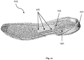
- Fig. 2c shows a lateral view of the midsole 105 with the cushioning element 110 and the second reinforcing element 140 of the sole element 100, as shown in Fig. 2a .
- the second reinforcing element 140 comprises ethylene-vinyl acetate, EVA, which distinguishes itself by a high stability and relatively good cushioning properties. It is also conceivable that other appropriate materials may be used, e.g. thermoplastic polyurethane, TPU, rubber, polypropylene, PP, or polystyrene, PS, etc. or that a material with fibers may be used as mentioned above for the sole plate 120 and the first reinforcing element 130.
- EVA ethylene-vinyl acetate
- the second reinforcing element 140 wraps the cushioning element 110 of the midsole 105 at least partly.
- a rim may be provided for further stability of the cushioning element 110 and thus for the midsole 105 and for the sole element 100.
- such a rim together with the sole plate 120 and the first reinforcing element 130 provides better energy return, ample cushioning, lesser weight and improved stability.
- the second reinforcing element 140 is essentially U shaped and wraps the cushioning element 110 along the medial side around the toe region 125 to the lateral side of the midsole 105.
- the second reinforcing element 140 may wrap essentially the whole perimeter of the cushioning element 110 in order to provide increased stability.
- the midsole 105 comprises a recess 115 adapted to receive the first reinforcing element 130 and the sole plate 120 on top of the midsole 105.
- a recess 115 adapted to receive the first reinforcing element 130 and the sole plate 120 on top of the midsole 105.
- first reinforcing element 130 as shown in Fig. 2b is received on top of the midsole 105, it will be at least partly surrounded by the midsole 105.
- This embedding of the first reinforcing element 130 enables additional support to the midsole 105, because the occurring forces during running may be distributed uniformly to the material of the midsole 105 and an undesired shifting of the first reinforcing element 130 may be avoided.
- the recess 115 may have a depth in the range of 0.8 - 1.8 mm, preferably 1.0 - 1.6 mm, most preferably 1.1 - 1.5 mm.
- the sole plate 120 and the first reinforcing element 130 sit flush in the midsole 105.
- the recess 115 comprises three elongated grooves 116 adapted to receive the three elongated protrusions 135 of the first reinforcing element 130 as shown in Fig. 2b .
- Fig. 2d shows a lateral view of the outsole element 150 of the sole element 100, as shown in Fig. 2a .
- the outsole element 150 may be pre-manufactured, for example, by injection molding, compression molding, thermoforming or any other methods of converting 2D designs to 3D moldings as known to the skilled person in the art.
- the outsole element 150 comprises a first unconnected portion 150a and a second unconnected portion 150b, wherein the first unconnected portion 150a comprises a first plurality of shaped protrusions being different from a second plurality of shaped protrusions of the second unconnected portion 150b.
- the first plurality of shaped protrusions of the first unconnected portion 150a has a triangular profile to provide increased slip resistance to a long-distance runner during a heel strike.
- other profiles such a circular, angular or other geometrical shapes are also conceivable.
- the second plurality of shaped protrusions of the second unconnected portion 150b comprises an elongated straight shape.
- a first subset of the second plurality extends transversal, i.e. from a medial side of the outsole element 150 to a lateral side of the outsole element 150, or vice versa.
- a second subset of the second plurality extends longitudinally, i.e. from a heel region of the outsole element 150 to a toe region of the outsole element 150, or vice versa.
- the two subsets of the second unconnected portion 150b form a regular pattern. Additionately or alternatively, other geometries of the two subset or more than two subsets are also conceivable.
- Fig. 2e shows a longitudinal section of an exemplary sole element 100 according to the present invention.
- the sole plate 120 may allow a drop of the heel region 121 to the forefoot region 123 of the assembled sole element 100 in the range of 5 - 15 mm, preferably around 8 - 12 mm, most preferably 9 - 11 mm.
- the term "drop" as used in the present application is defined as the difference between the height of the sole element 100 at the heel region 121 of the sole element 100 and the height of the sole element 100 at the forefoot region 123 of the sole element 100. In other words, it is the offset in height between the heel region 121 of the sole element 100 and the forefoot region 123 of the sole element 100.
- Fig. 2f shows a top view of an exemplary sole element 100 according to the present invention.
- a flexing or bending position is along the metatarsal joint region 123b, wherein this position may be defined as the following: 70 to 75% of the sole plate 120 lengths on the medial side and 60 to 65 % of the sole plate 120 on the lateral side.
Landscapes
- Chemical & Material Sciences (AREA)
- Engineering & Computer Science (AREA)
- Materials Engineering (AREA)
- Footwear And Its Accessory, Manufacturing Method And Apparatuses (AREA)
Abstract
Description
- The present invention relates to a sole element, a shoe and methods for production thereof.
- The sole of a shoe is of critical importance both for the wearing comfort perceived by an athlete as well as to enable a maximum performance. An important aspect for both wearing comfort and performance is the stiffness of the sole. For example, at walking or gentle running speeds, a flexible sole may be perceived to be more comfortable by an athlete. However, at high running speeds a stiffer sole may be advantageous in order to prevent injury and to improve the performance of an athlete. Frequently, developers are therefore faced with a trade-off in order to provide a sole that is both comfortable, protects a wearer's foot, and enables maximum performance.
-
US 2018/0338568 A1 discloses a sole structure for an article of footwear comprising a sole plate including a midfoot region and at least one of a forefoot region and a heel region. The sole plate has an undulating profile at a transverse cross-section of the sole plate. The undulating profile includes multiple waves each having a crest and a trough. The sole plate has ridges corresponding with the crest and the trough of each wave and extending longitudinally throughout the midfoot region and the at least one of a forefoot region and a heel region. - Further prior art is disclosed in
US 2011 / 0 030 245 A1 ,US 2009 / 0 031584 A1 ,US 2014 / 0 202 039 A1 andUS 2019 / 0 150 563 A1 . - It is an object underlying the present invention to overcome said disadvantages of the prior art and provide an improved sole for a shoe.
- This object is accomplished by the teachings of the independent claims. Advantageous embodiments are contained in the dependent claims.
- In one embodiment, a sole element for a shoe, in particular a sports shoe, comprises (a.) a midsole and (b.) a sole plate with an anisotropic bending property, (c.) wherein the sole plate is arranged on top of the midsole. The anisotropic bending property of the sole plate allows an anisotropic bending of the sole element in one direction so that a maximum performance of a wearer of a shoe with the sole element can be achieved. Moreover, the inventors have realized that the arrangement of the sole plate on top of the midsole together with this specific bending property in one direction relates to improved ways of providing optimum wearing comfort for the wearer of a shoe. For example, the sole element of the present invention provides a more comfortable running experience as the sole plate is only stiff when needed and there is no discomfort coming from the sole plate, e.g. during push off, but flexible during landing and in the transition period of the gait cycle of the wearer, such as a long-distance runner. Therefore, a positive impact on running economy of the long-distance runner may be achieved without any loss of running comfort.
- The anisotropic bending property may be a bending stiffness allowing a dorsal flexion of the sole plate. The direction of bending of the sole element plays an important role for the wearing comfort and performance of a sole and thus of a shoe. The inventors have found that the dorsal flexion is an important factor for a very responsive running, in particular for the above-mentioned push off of the long-distance runner during a gait cycle. Moreover, it helps to reduce injuries of the forefoot, because a sideways slipping of the forefoot may be avoided.
- It is noted that the terms "flexion" and "bending" as used in the present application maybe interchangeable. Moreover, the term "dorsal flexion" relates to an upward-bending in a region of the sole element. In contrast, the term "plantar flexion" relates to a downward-bending in a region of the sole element. Downwards is a direction towards the ground when the shoe with the sole element is worn in its usual configuration. Upwards is the opposite direction, e.g. towards the sky when the shoe is worn in a usual configuration. Moreover, it should be understood that the zero line to define a neutral position of these two different kinds of flexion (or bending) is a horizontal line through the elongated extension of the sole element.
- In some embodiments, the sole plate may have a first and a second bending stiffness for allowing a dorsal flexion of the sole plate, wherein the first bending stiffness is lower than the second bending stiffness. Moreover, the sole plate may have the first bending stiffness below a first dorsal flexion angle and the second bending stiffness above the first dorsal flexion angle.
- All of these described embodiments follow the same idea of further optimizing the mentioned bending stiffness for a sole element. For example, if the sole plate has a first bending stiffness and a second bending stiffness, both for bending upwards in the toe region of the sole element, wherein the first bending stiffness is lower than the second bending stiffness, the sole element may engage optimally during running but prevent injury to the foot due to an excessive upwards bending of the toes.
- In one embodiment, the first dorsal flexion angle is in the range of 20° - 40°, preferably in the range of 25° - 35°, most preferably 28° - 32°. The indicated values have been found to provide a reasonable compromise between needed stiffness for performance during push off, in particular when trying to bend the sole element to a certain angle, and sufficient flexibility to provide enough wearing comfort during landing of the shoe. The push off here refers to the action wherein the long-distance runner needs to push his or her foot off the ground with each step while running, whereas landing refers to the action wherein the long-distance runner lands on the ground surface with his or her foot at the end of each stride.
- In one embodiment, the sole plate is pre-bent in the forefoot region of the sole plate, preferably at an angle between 20° - 40° compared to the above-mentioned horizontal line through the elongated extension of the sole element. In other words, in a resting state without any occurring forces for bending or flexion, the forefoot region of the sole plate may bend upwards at an angle which may lie between 20° - 40°.
- The anisotropic bending property maybe in a forefoot region of the sole plate, preferably in a metatarsal region of the sole plate, most preferably in a metatarsal joint region of the sole plate. Therefore, the bending stiffness of the sole element allowing a dorsal flexion may be improved since this position of the flexion angle on the sole plate is anatomically positioned to the optimal needs for long-distance runners. A torsional movement during landing of the shoe may be allowed and an energy loss around the metatarsal joints maybe avoided.
- The sole plate may allow a drop of a heel region to a forefoot region of the sole element in the range of 5 - 15 mm, preferably around 8 - 12 mm, most preferably 9 - 11 mm. The term "drop" as used in the present application is defined as the difference between the height of the sole element at the heel region and the height of the sole element at the forefoot region of the sole element. In other words, it is the offset in height between the heel region of the shoe and the forefoot region of the shoe. Such a drop of the sole element provides sufficient cushioning in the somewhat rigid heel region of the sole element as well as improved bending stiffness in the forefoot region.
- In some embodiments, the sole element may comprise a first height at a metatarsal region of the sole element in the range of 8 - 17 mm, preferably 10 - 15 mm, most preferably 11 - 14 mm, and/or a second height at a heel region of the sole element in the range of 16 - 26 mm, preferably 18 - 24 mm, most preferably 19 - 23 mm. Here, the inventors have realized that these indicated values for the heights of the sole element under the foot of the long-distance runner above the ground have a positive impact on efficiency.
- The sole plate may comprise a material with fibers. Moreover, the material may comprise glass. Fiber or fiber composite materials are lightweight yet exceptionally strong. In particular, glass or glass fibers are fairly cheap and are moisture resistant as well as have a high strength to weight ratio. Moreover, fibers in general can be processed in various ways.
- In some embodiments, the sole element may further comprise a first reinforcing element. Moreover, the first reinforcing element may be arranged below the sole plate. Furthermore, the first reinforcing element may be arranged in a midfoot region of the sole plate. A reinforcing element serves to increase the stability of the sole element in selected regions. Moreover, such embodiment for a reinforcing element may act as a torsion and/or stabilizing element in the midfoot region and provide additional midfoot bending support as well as increased midfoot bending stiffness. In particular, together with the above-mentioned bending stiffness for the forefoot region due to the sole plate itself, an optimized ratio of bending for these two regions may be maintained to avoid any injuries to the foot, because the midfoot of the shoe should be stiffer than the forefoot.
- The first reinforcing element may be at least partly surrounded by the midsole. Such an arrangement of the first reinforcing element may provide additional support, because the occurring forces during running may be distributed uniformly to the material of the midsole.
- The first reinforcing element may comprise a thermoplastic polyurethane, TPU. This material has a high abrasion resistance. In particular in combination with a midsole which may comprise randomly arranged particles which, for their part, may comprise expanded thermoplastic polyurethane, such a reinforcing element can be used advantageously, as it can form a chemical bond with the expanded particles which is extremely durable and resistant and does not require an additional use of adhesives. This makes the manufacture of such sole elements easier, more cost-effective and more environment-friendly.
- In some embodiments, the midsole may comprise a recess adapted to receive the sole plate on top of the midsole. Moreover, the recess may be further adapted to receive the first reinforcing element on top of the midsole. In other words, the sole plate together with the reinforcing element below the sole plate may be placed in the recess as a kind of cavity so that the two components may be firmly secured on top of the midsole. This provides more stability to the long-distance runner.
- The recess may have a depth in the range of 0.8 - 1.8 mm, preferably 1.0 - 1.6 mm, most preferably 1.1 - 1.5 mm. This embodiment allows the sole plate to sit flush in the midsole. Therefore, the long-distance runner will not feel the stiff sole plate and it will not be uncomfortable when running.
- In some embodiments, the midsole may further comprise a second reinforcing element. Generally, the second reinforcing element may also act as a torsion and/or stabilizing element for the midsole element and at the same time act as a further cushioning element together with a cushioning element of the midsole. Moreover, the second reinforcing element may comprise ethylene-vinyl acetate, EVA. This material distinguishes itself by a high stability, low weight and relatively good cushioning properties.
- The second reinforcing element may wrap a cushioning element of the midsole at least partly. This enables to provide further stability for the sole element in the form of a rim. Moreover, such a rim together with the sole plate and the first reinforcing element, both placed in the midsole, provides better energy return, ample cushioning, lesser weight and improved stability.
- The midsole may comprise particles of an expanded material. The particles may, or may not, be randomly arranged. The use of particles of an expanded material facilitates the manufacture of such a midsole considerably, since the particles can be handled particularly easily. So, for instance, the particles can be filled, under pressure or by using a transport fluid, into a mold used for producing the sole element and the midsole, respectively.
- The expanded material may comprise an expanded thermoplastic polyurethane, eTPU. This material distinguishes itself by means of its particularly good elastic and cushioning properties and high energy return, i.e. a large proportion of the energy absorbed on impact is returned. This is particularly advantageous in embodiments of soles for long-distance runners.
- The sole element may further comprise an outsole element. Moreover, the outsole element may comprise at least two unconnected portions. Furthermore, the at least two unconnected portions may comprise different pluralities of different shaped protrusions. This enables more support for the whole sole element and provides a high degree of design freedom for individual needs of long-distance runners.
- Another aspect of the invention is directed to a shoe, in particular a sports shoe, which comprises a sole element as described herein. The shoe thus comprises a lightweight, durable sole element that offers optimum support and wearing comfort.
- Moreover, the shoe may further comprise at least one of the following: an upper, a strobel board and a sockliner, wherein the sockliner preferably comprises ethylene-vinyl acetate, EVA.
- The invention further concerns a method of producing a sole element for a shoe as described herein. The method may comprise the steps of (a.) providing a midsole and (b.) providing a sole plate with an anisotropic bending property on top of the midsole. Moreover, the sole element may comprise at least one of the following: a first reinforcing element, a second reinforcing element and an outsole element as described herein.
- The invention also concerns a method of producing a shoe as described herein comprising the steps of (a.) attaching the upper to the sole element, (b.) arranging the strobel board on top of the sole plate and (c.) arranging the sockliner on top of the strobel board.
- All described embodiments relate to improved methods of providing optimum bending stiffness in a sole element or a shoe. Further details and technical effects and advantages are described in detail above with respect to the sole element or the shoe.
- In the following, exemplary embodiments of the invention are described with reference to the figures.
- Fig. 1:
- illustrates an anisotropic bending property of an exemplary sole plate for a sole element according to the invention;
- Fig. 2a:
- shows an exploded view of an exemplary sole element according to the present invention;
- Fig. 2b:
- shows two lateral views of an exemplary sole plate with a first reinforcing element for a sole element according to the present invention;
- Fig. 2c:
- shows a lateral view of an exemplary midsole with a cushioning element and a second reinforcing element for a sole element according to the present invention; and
- Fig. 2d:
- shows a lateral view of an exemplary outsole element for a sole element according to the present invention;
- Fig. 2e:
- shows a longitudinal section of an exemplary sole element according to the present invention; and
- Fig. 2f:
- shows a top view of an exemplary sole element according to the present invention.
- In the following some embodiments of the invention are described in detail with particular reference to a sole element for a shoe, in particular a sports shoe for long-distance runner. However, the concept of the present invention may identically or similarly be applied to other shoes such as, for example, casual shoes, lace-up shoes, laceless shoes or boots such as working boots or any sports equipment.
- It is to be understood that these exemplary embodiments can be modified in a number of ways and combined with each other whenever compatible and that certain features may be omitted in so far as they appear dispensable.
-
Fig. 1 schematically illustrates the principle of an anisotropic bending property of asole plate 120 for a sole element according to the invention. As can be seen, thesole element 120 comprises aheel region 121, amidfoot region 122, aforefoot region 123 and atoe region 124. Moreover, theforefoot region 123 of the sole element comprises partly ametatarsal region 123a which includes a metatarsaljoint region 123b. It should be noted that these regions for thesole plate 120 also apply for thesole element 100 comprising thesole plate 120 as well as for other elements of thesole element 100, as shown and explained below in the remainingFigs. 2a-f . - The anisotropic bending property of the
sole plate 120 may be a bending stiffness allowing a dorsal flexion. As mentioned above, the terms "flexion" and "bending" maybe interchangeable. Moreover, the term "dorsal flexion" relates to a bending upwards in a region of thesole element 120. In contrast, the term "plantar flexion" relates to a bending downwards in a region of thesole element 120. Downwards is a direction towards the ground when a shoe with the sole element including thesole plate 120 is worn in its usual configuration. Upwards is an opposite direction, e.g. towards the sky when such a shoe is worn in a usual configuration. Moreover, the term "stiffness" is given by the slope of the stress-strain curve, which, simply speaking, plots the applied force over the resultant deformation. - As can be seen in
Fig. 1 , the dashed horizontal line through the elongated extension of thesole plate 120 is the zero line to define a neutral position of the two different kinds of flexion (or bending). Thus, thesole plate 120 ofFig. 1 allows a dorsal flexion or bending upwards of thesole plate 120 with respect to the zero line. Thesole plate 120 has a first and a second bending stiffness for allowing the dorsal flexion of thesole plate 120, wherein the first bending stiffness is lower than the second bending stiffness. As mentioned, different bending stiffnesses enable to meet individual requirements of long-distance runners. - Moreover, the
sole plate 120 has the first bending stiffness below a first dorsal flexion angle (a) defining a certain angle range, as shown with the double arrow inFig. 1 . The first dorsal flexion angle (a) may in the range of 20° - 40°, preferably in the range of 25° - 35°, most preferably 28° - 32°. Additionately or alternatively, other ranges could also be possible depending on specific requirements of the wearer, e.g. the weight or other anatomic conditions such as supination or pronation, etc., or specific running conditions, e.g. uphill running or flat-ground running, etc. The second bending stiffness is above the first dorsal flexion angle (α), as shown with the single arrow inFig. 1 . - The first bending stiffness is lower than the second bending stiffness. Such a first bending stiffness below the first dorsal flexion angle (α) provides sufficient flexibility for enough wearing comfort during landing of a shoe with the
sole plate 120 whereas the second bending stiffness above the first dorsal flexion angle (α) provides needed stiffness for performance during push off, in particular when trying to bend thesole plate 120 and thus the whole sole element and the shoe. - As can be seen in
Fig. 1 , the anisotropic bending property is located in theforefoot region 123 of thesole plate 120. The location of the bending property may be characterized by the bending or flexing position on the zero line where thesole plate 120 starts to bend. Moreover, a certain area around this bending or flexing position may be in themetatarsal region 123a of thesole plate 120, preferably along the metatarsaljoint region 123b of thesole plate 120. -
Fig. 2a shows an exploded view of an exemplarysole element 100 according to the present invention.Fig. 2b shows two lateral views of an exemplarysole plate 120 as shown inFig. 1 with a first reinforcingelement 130 of thesole element 100.Fig. 2c shows a lateral view of anexemplary midsole 105 with acushioning element 110 and a second reinforcingelement 140 of thesole element 100.Fig. 2d shows a lateral view of anexemplary outsole element 150 of thesole element 100.Fig. 2e shows a longitudinal section of an exemplarysole element 100 according to the present invention.Fig. 2f shows a top view of an exemplarysole element 100 according to the present invention. - As can be seen in
Fig. 2a , thesole element 100 for a shoe according to the invention comprises amidsole 105 and asole plate 120 with an anisotropic bending property, wherein thesole plate 120 is arranged on top of themidsole 105. Such an arrangement of thesole plate 120 on top of themidsole 105 together with the specific bending property in one direction relates to improved ways of providing optimum bending properties, for example bending stiffness in thesole element 100, together with optimum wearing comfort for the long-distance runner of a shoe with thissole element 100. Thesole plate 120 may comprise one or more of the above explained features of the embodiment ofFig. 1 . - The
midsole 105 comprises acushioning element 110 that is manufactured from a large number of particles. The particles are made from an expanded material such as expanded thermoplastic polyurethane, eTPU. It is also conceivable that any other appropriate material maybe used, for example, any other particle foam suitable for the manufacture of midsoles, for example,expanded polyamide, ePA; expanded polyether-block-amide, ePEBA; expanded polylactide, ePLA; expanded polyethylene terephthalate, ePET; expanded polybutylene terephthalate, ePBT; expanded thermoplastic polyester ether elastomer, eTPEE. - Moreover, the expanded particles are randomly arranged inside the
cushioning element 110. Alternatively, the expanded particles may be arranged with a certain pattern inside thecushioning element 110. Further features of thecushioning element 110 will be explained with respect toFig. 2c . - The
sole plate 120 comprises a material with fibers. Carbon fibers or carbon fiber composite materials may be possible materials, because they are lightweight yet exceptionally strong. Glass or Glass fibers are also conceivable materials, because they are fairly cheap and are moisture resistant as well as have a high strength to weight ratio. Moreover, glass fibers may be processed in various ways. Additionately or alternatively, any material or mixture of materials which may provide sufficient stiffness in combination with a low weight that may be engineered to provide flexibility in certain angles may be used. - The assembled
sole element 100 may comprise a first height at themetatarsal region 124 of the assembledsole element 100 in the range of 8 - 17 mm, preferably 10 - 15 mm, most preferably 11 - 14 mm, and/or a second height at theheel region 121 of the assembledsole element 100 in the range of 16 - 26 mm, preferably 18 - 24 mm, most preferably 19 - 23 mm. -
Fig. 2b shows two lateral views of the exemplarysole plate 120 together with the first reinforcingelement 130 of thesole element 100, as shown inFigs. 1 and2a . The first reinforcingelement 130 is arranged below thesole plate 120 so that the wearing comfort is not compromised for a long-distance runner. Therefore, the first reinforcingelement 130 may also be adapted to the curvature of thesole plate 120. - The first reinforcing
element 130 is arranged in themidfoot region 122 of thesole plate 120. The first reinforcing element may act as a torsion and/or stabilizing element in themidfoot region 122 and provide additional midfoot bending support and increased midfoot bending stiffness to a long-distance runner. In particular, together with the first bending stiffness below the first dorsal flexion angle of thesole plate 120, an optimized ratio of bending formidfoot region 122 may be maintained to avoid any injuries to the foot, because themidfoot region 122 of thesole element 120 should be stiffer than other regions, e.g. theforefoot region 123. Additionately or alternatively, a plurality of first reinforcing elements is also conceivable to improve this effect. Some of this plurality of first reinforcing elements may also be arranged in other regions of thesole plate 120 to provide more stiffness. - The first reinforcing
element 130 comprises a thermoplastic polyurethane, TPU, which is very abrasion-resistant and tear-resistant. It is also conceivable that other appropriate materials may be used, e.g. carbon, polyamide, rubber, polypropylene, PP, polystyrene, PS, etc. or that a material with fibers may be used as mentioned above for thesole plate 120. - The first reinforcing
element 130 further comprises three elongatedprotrusions 135. They may provide more stiffness in themidfoot region 122 of thesole element 120 and improved stability for torsional movements. More or less protrusions are also conceivable depending on the requirements of the long-distance runner. Non-elongated shapes having a geometrical profile such as dots, rectangles, triangles, etc. may be also used. Theprotrusions 135 also ensure a better attachment, grip or fit of the first reinforcing element to themidsole 105. -
Fig. 2c shows a lateral view of themidsole 105 with thecushioning element 110 and the second reinforcingelement 140 of thesole element 100, as shown inFig. 2a . - The second reinforcing
element 140 comprises ethylene-vinyl acetate, EVA, which distinguishes itself by a high stability and relatively good cushioning properties. It is also conceivable that other appropriate materials may be used, e.g. thermoplastic polyurethane, TPU, rubber, polypropylene, PP, or polystyrene, PS, etc. or that a material with fibers may be used as mentioned above for thesole plate 120 and the first reinforcingelement 130. - As can be seen in
Fig. 2c , the second reinforcingelement 140 wraps thecushioning element 110 of themidsole 105 at least partly. In other words, a rim may be provided for further stability of thecushioning element 110 and thus for themidsole 105 and for thesole element 100. Moreover, such a rim together with thesole plate 120 and the first reinforcingelement 130 provides better energy return, ample cushioning, lesser weight and improved stability. - As shown in
Fig. 2a , the second reinforcingelement 140 is essentially U shaped and wraps thecushioning element 110 along the medial side around the toe region 125 to the lateral side of themidsole 105. Additionately or alternatively, the second reinforcingelement 140 may wrap essentially the whole perimeter of thecushioning element 110 in order to provide increased stability. - The
midsole 105 comprises arecess 115 adapted to receive the first reinforcingelement 130 and thesole plate 120 on top of themidsole 105. Such an arrangement together with the anisotropic bending property of thesole plate 120 provides optimum bending properties together with optimum wearing comfort for the wearer of a shoe. - Moreover, if the first reinforcing
element 130 as shown inFig. 2b is received on top of themidsole 105, it will be at least partly surrounded by themidsole 105. This embedding of the first reinforcingelement 130 enables additional support to themidsole 105, because the occurring forces during running may be distributed uniformly to the material of themidsole 105 and an undesired shifting of the first reinforcingelement 130 may be avoided. - The
recess 115 may have a depth in the range of 0.8 - 1.8 mm, preferably 1.0 - 1.6 mm, most preferably 1.1 - 1.5 mm. Thus, thesole plate 120 and the first reinforcingelement 130 sit flush in themidsole 105. Moreover, therecess 115 comprises threeelongated grooves 116 adapted to receive the threeelongated protrusions 135 of the first reinforcingelement 130 as shown inFig. 2b . -
Fig. 2d shows a lateral view of theoutsole element 150 of thesole element 100, as shown inFig. 2a . - The
outsole element 150 may be pre-manufactured, for example, by injection molding, compression molding, thermoforming or any other methods of converting 2D designs to 3D moldings as known to the skilled person in the art. - As can be seen in
Fig. 2d , theoutsole element 150 comprises a firstunconnected portion 150a and a secondunconnected portion 150b, wherein the firstunconnected portion 150a comprises a first plurality of shaped protrusions being different from a second plurality of shaped protrusions of the secondunconnected portion 150b. - The first plurality of shaped protrusions of the first
unconnected portion 150a has a triangular profile to provide increased slip resistance to a long-distance runner during a heel strike. Additionately or alternatively, other profiles such a circular, angular or other geometrical shapes are also conceivable. - The second plurality of shaped protrusions of the second
unconnected portion 150b comprises an elongated straight shape. A first subset of the second plurality extends transversal, i.e. from a medial side of theoutsole element 150 to a lateral side of theoutsole element 150, or vice versa. A second subset of the second plurality extends longitudinally, i.e. from a heel region of theoutsole element 150 to a toe region of theoutsole element 150, or vice versa. Thus, the two subsets of the secondunconnected portion 150b form a regular pattern. Additionately or alternatively, other geometries of the two subset or more than two subsets are also conceivable. -
Fig. 2e shows a longitudinal section of an exemplarysole element 100 according to the present invention. - The
sole plate 120 may allow a drop of theheel region 121 to theforefoot region 123 of the assembledsole element 100 in the range of 5 - 15 mm, preferably around 8 - 12 mm, most preferably 9 - 11 mm. The term "drop" as used in the present application is defined as the difference between the height of thesole element 100 at theheel region 121 of thesole element 100 and the height of thesole element 100 at theforefoot region 123 of thesole element 100. In other words, it is the offset in height between theheel region 121 of thesole element 100 and theforefoot region 123 of thesole element 100. -
Fig. 2f shows a top view of an exemplarysole element 100 according to the present invention. In this embodiment, a flexing or bending position is along the metatarsaljoint region 123b, wherein this position may be defined as the following: 70 to 75% of thesole plate 120 lengths on the medial side and 60 to 65 % of thesole plate 120 on the lateral side. - In the following, further embodiments are described to facilitate the understanding of the invention:
- 1. A sole element (100) for a shoe, in particular a sports shoe, comprising:
- (a.) a midsole (105); and
- (b.) a sole plate (120) with an anisotropic bending property;
- (c.) wherein the sole plate (120) is arranged on top of the midsole (105).
- 2. The sole element (100) of embodiment 1, wherein the anisotropic bending property is a bending stiffness allowing a dorsal flexion of the sole plate (120).
- 3. The sole element (100) of embodiment 1 or 2, wherein the sole plate (120) has a first and a second bending stiffness for allowing a dorsal flexion of the sole plate (120), wherein the first bending stiffness is lower than the second bending stiffness.
- 4. The sole element (100) of embodiment 3, wherein the sole plate (120) has the first bending stiffness below a first dorsal flexion angle and the second bending stiffness above the first dorsal flexion angle.
- 5. The sole element (100) of embodiment 4, wherein the first dorsal flexion angle is in the range of 20° - 40°, preferably in the range of 25° - 35°, most preferably 28° - 32°.
- 6. The sole element (100) of one of the preceding embodiments, wherein the anisotropic bending property is in a forefoot region (123) of the sole plate (120), preferably in a metatarsal region (123a) of the sole plate (120), most preferably in a metatarsal joint region (123b) of the sole plate (120).
- 7. The sole element (100) of one of the preceding embodiments, wherein the sole plate (120) allows a drop of a heel region (121) to a forefoot region (123) of the sole element (100) in the range of 5 - 15 mm, preferably around 8 - 12 mm, most preferably 9 - 11 mm.
- 8. The sole element (100) of one of the preceding embodiments, comprising a first height at a metatarsal region (123a) of the sole element (100) in the range of 8 - 17 mm, preferably 10 - 15 mm, most preferably 11 - 14 mm, and/or a second height at a heel region (121) of the sole element (100) in the range of 16 - 26 mm, preferably 18 - 24 mm, most preferably 19 - 23 mm.
- 9. The sole element (100) of one of the preceding embodiments, wherein the sole plate (120) comprises a material with fibers.
- 10. The sole element (100) of the preceding embodiment, wherein the material comprises glass.
- 11. The sole element (100) of one of the preceding embodiments, further comprising a first reinforcing element (130).
- 12. The sole element (100) of the preceding embodiment, wherein the first reinforcing element (130) is arranged below the sole plate (120).
- 13. The sole element (100) of embodiment 11 or 12, wherein the first reinforcing element (130) is arranged in a midfoot region (122) of the sole plate (120).
- 14. The sole element (100) of one of embodiments 11 - 13, wherein the first reinforcing element (130) is at least partly surrounded by the midsole (105).
- 15. The sole element (100) of one of embodiments 11 - 14, wherein the first reinforcing element (130) comprises a thermoplastic polyurethane, TPU.
- 16. The sole element (100) of one of preceding embodiments, wherein the midsole (105) comprises a recess (115) adapted to receive the sole plate (120) on top of the midsole (105).
- 17. The sole element (100) of the preceding embodiment, wherein the recess (115) is further adapted to receive the first reinforcing element (130) on top of the midsole (105).
- 18. The sole element (100) of embodiment 16 or 17, wherein the recess (115) has a depth in the range of 0.8 - 1.8 mm, preferably 1.0 - 1.6 mm, most preferably 1.1 -1.5 mm.
- 19. The sole element (100) of one of preceding embodiments, wherein the midsole (105) comprises a second reinforcing element (140).
- 20. The sole element (100) of the preceding embodiment, wherein the second reinforcing element (140) comprises ethylene-vinyl acetate, EVA.
- 21. The sole element of embodiment 19 or 20, wherein the second reinforcing element (140) wraps a cushioning element (110) of the midsole (105) at least partly.
- 22. The sole element (100) of one of preceding embodiments, wherein the midsole (105) comprises particles of an expanded material.
- 23. The sole element (100) of the preceding embodiment, wherein the expanded material comprises an expanded thermoplastic polyurethane, eTPU.
- 24. The sole element (100) of one of preceding embodiments, further comprising an outsole element (150).
- 25. The sole element (100) of the preceding embodiment, wherein the outsole element (150) comprises at least two unconnected portions (150a, 150b).
- 26. The sole element (100) of the preceding embodiment, wherein the at least two unconnected portions (150a, 150b) comprise different pluralities of different shaped protrusions.
- 27. A shoe, in particular a sports shoe, comprising a sole element (100) of one of the preceding embodiments.
- 28. The shoe of the preceding embodiment, further comprising at least one of the following: an upper, a strobel board and a sockliner, wherein the sockliner preferably comprises ethylene-vinyl acetate, EVA.
- 29. A method of producing a sole element (100) for a shoe of one of the embodiments 1 - 26, comprising:
- (a.) providing a midsole (105); and
- (b.) providing a sole plate (120) with an anisotropic bending property on top of the midsole (105).
- 30. The method of the preceding embodiment, further providing at least one of the following: a first reinforcing element (130), a second reinforcing element (140) and an outsole element (150).
- 31. A method of producing a shoe of embodiment 28, comprising:
- (a.) attaching the upper to the sole element (100);
- (b.) arranging the strobel board on top of the sole plate (120); and
- (c.) arranging the sockliner on top of the strobel board.
Claims (15)
- A sole element (100) for a shoe, in particular a sports shoe, comprising:(a.) a midsole (105); and(b.) a sole plate (120) with an anisotropic bending property;(c.) wherein the sole plate (120) is arranged on top of the midsole (105).
- The sole element (100) of claim 1, wherein the anisotropic bending property is a bending stiffness allowing a dorsal flexion of the sole plate (120).
- The sole element (100) of claim 1 or 2, wherein the sole plate (120) has a first and a second bending stiffness for allowing a dorsal flexion of the sole plate (120), wherein the first bending stiffness is lower than the second bending stiffness.
- The sole element (100) of claim 3, wherein the sole plate (120) has the first bending stiffness below a first dorsal flexion angle and the second bending stiffness above the first dorsal flexion angle.
- The sole element (100) of claim 4, wherein the first dorsal flexion angle is in the range of 20° - 40°, preferably in the range of 25° - 35°, most preferably 28° - 320.
- The sole element (100) of one of the preceding claims, wherein the anisotropic bending property is in a forefoot region (123) of the sole plate (120), preferably in a metatarsal region (123a) of the sole plate (120), most preferably in a metatarsal joint region (123b) of the sole plate (120).
- The sole element (100) of one of the preceding claims, wherein the sole plate (120) allows a drop of a heel region (121) to a forefoot region (123) of the sole element (100) in the range of 5 - 15 mm, preferably around 8 - 12 mm, most preferably 9 - 11 mm.
- The sole element (100) of one of the preceding claims, further comprising a first reinforcing element (130).
- The sole element (100) of one of preceding claims, wherein the midsole (105) comprises a recess (115) adapted to receive the sole plate (120) on top of the midsole (105).
- The sole element (100) of the preceding claim, wherein the recess (115) is further adapted to receive the first reinforcing element (130) on top of the midsole (105).
- The sole element (100) of claim 9 or 10, wherein the recess (115) has a depth in the range of 0.8 - 1.8 mm, preferably 1.0 - 1.6 mm, most preferably 1.1 - 1.5 mm.
- The sole element (100) of one of preceding claims, wherein the midsole (105) comprises particles of an expanded material.
- A shoe, in particular a sports shoe, comprising a sole element (100) of one of the preceding claims and at least one of the following: an upper, a strobel board and a sockliner, wherein the sockliner preferably comprises ethylene-vinyl acetate, EVA.
- A method of producing a sole element (100) for a shoe of one of the claims 1 - 12, comprising:(a.) providing a midsole (105); and(b.) providing a sole plate (120) with an anisotropic bending property on top of the midsole (105).
- A method of producing a shoe of claim 13, comprising:(a.) attaching the upper to the sole element (100);(b.) arranging the strobel board on top of the sole plate (120); and(c.) arranging the sockliner on top of the strobel board.
Applications Claiming Priority (1)
| Application Number | Priority Date | Filing Date | Title |
|---|---|---|---|
| DE102019214944.8A DE102019214944A1 (en) | 2019-09-27 | 2019-09-27 | Sole element |
Publications (1)
| Publication Number | Publication Date |
|---|---|
| EP3797627A1 true EP3797627A1 (en) | 2021-03-31 |
Family
ID=72422069
Family Applications (1)
| Application Number | Title | Priority Date | Filing Date |
|---|---|---|---|
| EP20194690.2A Pending EP3797627A1 (en) | 2019-09-27 | 2020-09-04 | Sole element |
Country Status (5)
| Country | Link |
|---|---|
| US (1) | US20210093039A1 (en) |
| EP (1) | EP3797627A1 (en) |
| JP (3) | JP7053744B2 (en) |
| CN (2) | CN115251529B (en) |
| DE (1) | DE102019214944A1 (en) |
Families Citing this family (6)
| Publication number | Priority date | Publication date | Assignee | Title |
|---|---|---|---|---|
| EP4346488A1 (en) * | 2021-05-28 | 2024-04-10 | Nike Innovate C.V. | Sole structure for article of footwear |
| US12114735B2 (en) | 2021-12-16 | 2024-10-15 | Jeffery Stuart Goff | Multiple cleat plate sole |
| US12250986B2 (en) * | 2022-02-25 | 2025-03-18 | Nike, Inc. | Article of footwear |
| KR102641919B1 (en) * | 2022-09-28 | 2024-02-27 | 김천대학교산학협력단 | Real-time feedback-based virtual reality walking system using smart insole |
| DE102023210927A1 (en) * | 2023-11-03 | 2025-05-08 | Adidas Ag | Sole comprising a reinforcing frame |
| JP2026059891A (en) | 2024-09-27 | 2026-04-08 | 株式会社アシックス | Plates, soles, and shoes |
Citations (9)
| Publication number | Priority date | Publication date | Assignee | Title |
|---|---|---|---|---|
| US20090031584A1 (en) | 2006-03-30 | 2009-02-05 | Rasmussen Bret S | Shoe Stability Layer Apparatus And Method |
| US20100307025A1 (en) * | 2008-02-27 | 2010-12-09 | Ecco Sko A/S | Midsole for a shoe, in particular a running shoe |
| US20110030245A1 (en) | 2008-07-05 | 2011-02-10 | Ecco Sko A/S | Sole for a shoe, in particular for a running shoe |
| US20140202039A1 (en) | 2008-12-09 | 2014-07-24 | Red Wing Shoe Company, Inc. | Molded insole for welted footwear |
| US20180132564A1 (en) * | 2016-11-11 | 2018-05-17 | Nike, Inc. | Plate with foam for footwear |
| US20180199665A1 (en) * | 2015-06-02 | 2018-07-19 | Under Armour, Inc. | Footwear including lightweight sole structure providing enhanced comfort, flexibility and performance features |
| US20180222148A1 (en) * | 2015-12-02 | 2018-08-09 | Carbitex, Inc. | Joined fiber-reinforced composite material assembly with tunable anisotropic properties |
| US20180338568A1 (en) | 2017-05-23 | 2018-11-29 | Nike, Inc. | Sole structure for an article of footwear with undulating sole plate |
| US20190150563A1 (en) | 2017-11-21 | 2019-05-23 | Altra Llc | Spring mechanism in a shoe |
Family Cites Families (10)
| Publication number | Priority date | Publication date | Assignee | Title |
|---|---|---|---|---|
| JP4210585B2 (en) * | 2003-12-02 | 2009-01-21 | マドラス株式会社 | shank |
| JP4087333B2 (en) * | 2003-12-26 | 2008-05-21 | Sriスポーツ株式会社 | shoes |
| GB0609808D0 (en) * | 2006-05-17 | 2006-06-28 | Berghaus Ltd | Footwear sole |
| DE102008064493A1 (en) * | 2008-12-23 | 2010-06-24 | Adidas International Marketing B.V. | sole |
| US9833039B2 (en) * | 2013-09-27 | 2017-12-05 | Nike, Inc. | Uppers and sole structures for articles of footwear |
| DE102014206419B4 (en) * | 2014-04-03 | 2020-02-20 | Adidas Ag | Support element for shoes and sole and shoe with such a support element |
| WO2017048937A1 (en) * | 2015-09-18 | 2017-03-23 | Nike Innovate C.V. | Footwear sole structure with nonlinear bending stiffness |
| MX392120B (en) * | 2015-10-02 | 2025-03-21 | Nike Innovate Cv | SHOE PLATE. |
| US10660400B2 (en) * | 2016-08-25 | 2020-05-26 | Nike, Inc. | Sole structure for an article of footwear having grooves and a flex control insert with ribs |
| US11583029B2 (en) * | 2018-01-22 | 2023-02-21 | Adidas Ag | Article of footwear with ribbed outsole and notched midsole |
-
2019
- 2019-09-27 DE DE102019214944.8A patent/DE102019214944A1/en active Granted
-
2020
- 2020-09-04 EP EP20194690.2A patent/EP3797627A1/en active Pending
- 2020-09-16 JP JP2020155366A patent/JP7053744B2/en active Active
- 2020-09-22 US US17/028,469 patent/US20210093039A1/en active Pending
- 2020-09-24 CN CN202210890111.9A patent/CN115251529B/en active Active
- 2020-09-24 CN CN202011015966.4A patent/CN112568550B/en active Active
-
2022
- 2022-03-31 JP JP2022059046A patent/JP7324892B2/en active Active
-
2023
- 2023-07-31 JP JP2023124038A patent/JP7507293B2/en active Active
Patent Citations (9)
| Publication number | Priority date | Publication date | Assignee | Title |
|---|---|---|---|---|
| US20090031584A1 (en) | 2006-03-30 | 2009-02-05 | Rasmussen Bret S | Shoe Stability Layer Apparatus And Method |
| US20100307025A1 (en) * | 2008-02-27 | 2010-12-09 | Ecco Sko A/S | Midsole for a shoe, in particular a running shoe |
| US20110030245A1 (en) | 2008-07-05 | 2011-02-10 | Ecco Sko A/S | Sole for a shoe, in particular for a running shoe |
| US20140202039A1 (en) | 2008-12-09 | 2014-07-24 | Red Wing Shoe Company, Inc. | Molded insole for welted footwear |
| US20180199665A1 (en) * | 2015-06-02 | 2018-07-19 | Under Armour, Inc. | Footwear including lightweight sole structure providing enhanced comfort, flexibility and performance features |
| US20180222148A1 (en) * | 2015-12-02 | 2018-08-09 | Carbitex, Inc. | Joined fiber-reinforced composite material assembly with tunable anisotropic properties |
| US20180132564A1 (en) * | 2016-11-11 | 2018-05-17 | Nike, Inc. | Plate with foam for footwear |
| US20180338568A1 (en) | 2017-05-23 | 2018-11-29 | Nike, Inc. | Sole structure for an article of footwear with undulating sole plate |
| US20190150563A1 (en) | 2017-11-21 | 2019-05-23 | Altra Llc | Spring mechanism in a shoe |
Also Published As
| Publication number | Publication date |
|---|---|
| CN115251529B (en) | 2024-07-02 |
| JP7507293B2 (en) | 2024-06-27 |
| CN112568550B (en) | 2022-08-16 |
| JP7053744B2 (en) | 2022-04-12 |
| DE102019214944A1 (en) | 2021-04-01 |
| CN112568550A (en) | 2021-03-30 |
| US20210093039A1 (en) | 2021-04-01 |
| JP2022095780A (en) | 2022-06-28 |
| JP2023134847A (en) | 2023-09-27 |
| JP7324892B2 (en) | 2023-08-10 |
| JP2021053376A (en) | 2021-04-08 |
| CN115251529A (en) | 2022-11-01 |
Similar Documents
| Publication | Publication Date | Title |
|---|---|---|
| US11452335B2 (en) | Sole structure with plates and intervening fluid-filled bladder and method of manufacturing | |
| US20210093039A1 (en) | Sole element | |
| US20220151338A1 (en) | Footwear construction | |
| US10561198B2 (en) | Footwear including lightweight sole structure providing enhanced comfort, flexibility and performance features | |
| EP3302120B1 (en) | Foot support members that provide dynamically transformative properties | |
| US9003677B2 (en) | System and method for toning footwear | |
| US8146272B2 (en) | Outsole having grooves forming discrete lugs | |
| CN104486960B (en) | Footwear sole construction for article of footwear | |
| US7549236B2 (en) | Footwear with independent suspension and protection | |
| EP0878142B1 (en) | Athletic shoe midsole design and construction and process for manufacturing the same | |
| US12127627B2 (en) | Midsole having a clear free space | |
| EP4643696A1 (en) | Sole for a running shoe | |
| JP7779891B2 (en) | Shoe soles | |
| WO2025196682A1 (en) | Upgraded sole for running footwear and related running footwear |
Legal Events
| Date | Code | Title | Description |
|---|---|---|---|
| PUAI | Public reference made under article 153(3) epc to a published international application that has entered the european phase |
Free format text: ORIGINAL CODE: 0009012 |
|
| STAA | Information on the status of an ep patent application or granted ep patent |
Free format text: STATUS: REQUEST FOR EXAMINATION WAS MADE |
|
| 17P | Request for examination filed |
Effective date: 20200904 |
|
| AK | Designated contracting states |
Kind code of ref document: A1 Designated state(s): AL AT BE BG CH CY CZ DE DK EE ES FI FR GB GR HR HU IE IS IT LI LT LU LV MC MK MT NL NO PL PT RO RS SE SI SK SM TR |
|
| AX | Request for extension of the european patent |
Extension state: BA ME |
|
| RIN1 | Information on inventor provided before grant (corrected) |
Inventor name: BARTL, JOCHEN Inventor name: BRUNS, FALK Inventor name: FISCHEREHL Inventor name: SCHUSTER, BERNHARD Inventor name: GRUETTNER, MAXIMILIAN LENNART CHRISTOPH Inventor name: PATERSON, ROBBIE |
|
| STAA | Information on the status of an ep patent application or granted ep patent |
Free format text: STATUS: EXAMINATION IS IN PROGRESS |
|
| 17Q | First examination report despatched |
Effective date: 20230605 |