EP3797444B1 - Battery cell connector - Google Patents
Battery cell connector Download PDFInfo
- Publication number
- EP3797444B1 EP3797444B1 EP19707757.1A EP19707757A EP3797444B1 EP 3797444 B1 EP3797444 B1 EP 3797444B1 EP 19707757 A EP19707757 A EP 19707757A EP 3797444 B1 EP3797444 B1 EP 3797444B1
- Authority
- EP
- European Patent Office
- Prior art keywords
- area
- flat part
- battery cell
- cell connector
- receiving area
- Prior art date
- Legal status (The legal status is an assumption and is not a legal conclusion. Google has not performed a legal analysis and makes no representation as to the accuracy of the status listed.)
- Active
Links
Images


Classifications
-
- H—ELECTRICITY
- H01—ELECTRIC ELEMENTS
- H01M—PROCESSES OR MEANS, e.g. BATTERIES, FOR THE DIRECT CONVERSION OF CHEMICAL ENERGY INTO ELECTRICAL ENERGY
- H01M50/00—Constructional details or processes of manufacture of the non-active parts of electrochemical cells other than fuel cells, e.g. hybrid cells
- H01M50/50—Current conducting connections for cells or batteries
- H01M50/528—Fixed electrical connections, i.e. not intended for disconnection
-
- H—ELECTRICITY
- H01—ELECTRIC ELEMENTS
- H01M—PROCESSES OR MEANS, e.g. BATTERIES, FOR THE DIRECT CONVERSION OF CHEMICAL ENERGY INTO ELECTRICAL ENERGY
- H01M50/00—Constructional details or processes of manufacture of the non-active parts of electrochemical cells other than fuel cells, e.g. hybrid cells
- H01M50/50—Current conducting connections for cells or batteries
- H01M50/502—Interconnectors for connecting terminals of adjacent batteries; Interconnectors for connecting cells outside a battery casing
- H01M50/503—Interconnectors for connecting terminals of adjacent batteries; Interconnectors for connecting cells outside a battery casing characterised by the shape of the interconnectors
-
- H—ELECTRICITY
- H01—ELECTRIC ELEMENTS
- H01M—PROCESSES OR MEANS, e.g. BATTERIES, FOR THE DIRECT CONVERSION OF CHEMICAL ENERGY INTO ELECTRICAL ENERGY
- H01M50/00—Constructional details or processes of manufacture of the non-active parts of electrochemical cells other than fuel cells, e.g. hybrid cells
- H01M50/50—Current conducting connections for cells or batteries
- H01M50/502—Interconnectors for connecting terminals of adjacent batteries; Interconnectors for connecting cells outside a battery casing
- H01M50/521—Interconnectors for connecting terminals of adjacent batteries; Interconnectors for connecting cells outside a battery casing characterised by the material
- H01M50/522—Inorganic material
-
- H—ELECTRICITY
- H01—ELECTRIC ELEMENTS
- H01M—PROCESSES OR MEANS, e.g. BATTERIES, FOR THE DIRECT CONVERSION OF CHEMICAL ENERGY INTO ELECTRICAL ENERGY
- H01M50/00—Constructional details or processes of manufacture of the non-active parts of electrochemical cells other than fuel cells, e.g. hybrid cells
- H01M50/50—Current conducting connections for cells or batteries
- H01M50/502—Interconnectors for connecting terminals of adjacent batteries; Interconnectors for connecting cells outside a battery casing
- H01M50/521—Interconnectors for connecting terminals of adjacent batteries; Interconnectors for connecting cells outside a battery casing characterised by the material
- H01M50/526—Interconnectors for connecting terminals of adjacent batteries; Interconnectors for connecting cells outside a battery casing characterised by the material having a layered structure
-
- H—ELECTRICITY
- H01—ELECTRIC ELEMENTS
- H01R—ELECTRICALLY-CONDUCTIVE CONNECTIONS; STRUCTURAL ASSOCIATIONS OF A PLURALITY OF MUTUALLY-INSULATED ELECTRICAL CONNECTING ELEMENTS; COUPLING DEVICES; CURRENT COLLECTORS
- H01R4/00—Electrically-conductive connections between two or more conductive members in direct contact, i.e. touching one another; Means for effecting or maintaining such contact; Electrically-conductive connections having two or more spaced connecting locations for conductors and using contact members penetrating insulation
- H01R4/28—Clamped connections, spring connections
- H01R4/48—Clamped connections, spring connections utilising a spring, clip, or other resilient member
-
- H—ELECTRICITY
- H01—ELECTRIC ELEMENTS
- H01M—PROCESSES OR MEANS, e.g. BATTERIES, FOR THE DIRECT CONVERSION OF CHEMICAL ENERGY INTO ELECTRICAL ENERGY
- H01M2220/00—Batteries for particular applications
- H01M2220/20—Batteries in motive systems, e.g. vehicle, ship, plane
-
- H—ELECTRICITY
- H01—ELECTRIC ELEMENTS
- H01M—PROCESSES OR MEANS, e.g. BATTERIES, FOR THE DIRECT CONVERSION OF CHEMICAL ENERGY INTO ELECTRICAL ENERGY
- H01M50/00—Constructional details or processes of manufacture of the non-active parts of electrochemical cells other than fuel cells, e.g. hybrid cells
- H01M50/20—Mountings; Secondary casings or frames; Racks, modules or packs; Suspension devices; Shock absorbers; Transport or carrying devices; Holders
- H01M50/204—Racks, modules or packs for multiple batteries or multiple cells
- H01M50/207—Racks, modules or packs for multiple batteries or multiple cells characterised by their shape
- H01M50/213—Racks, modules or packs for multiple batteries or multiple cells characterised by their shape adapted for cells having curved cross-section, e.g. round or elliptic
-
- Y—GENERAL TAGGING OF NEW TECHNOLOGICAL DEVELOPMENTS; GENERAL TAGGING OF CROSS-SECTIONAL TECHNOLOGIES SPANNING OVER SEVERAL SECTIONS OF THE IPC; TECHNICAL SUBJECTS COVERED BY FORMER USPC CROSS-REFERENCE ART COLLECTIONS [XRACs] AND DIGESTS
- Y02—TECHNOLOGIES OR APPLICATIONS FOR MITIGATION OR ADAPTATION AGAINST CLIMATE CHANGE
- Y02E—REDUCTION OF GREENHOUSE GAS [GHG] EMISSIONS, RELATED TO ENERGY GENERATION, TRANSMISSION OR DISTRIBUTION
- Y02E60/00—Enabling technologies; Technologies with a potential or indirect contribution to GHG emissions mitigation
- Y02E60/10—Energy storage using batteries
Definitions
- a physical battery cell connector can be formed as an assembly and set up to electrically conductively connect a first cell terminal of a first electrochemical cell of an electrochemical device to a second cell terminal of a second electrochemical cell of the electrochemical device.
- An electrochemical device is in particular a battery, preferably a motor vehicle battery. Such a battery can be, for example, a battery of a drive train of the motor vehicle.
- BEV battery-operated electric vehicles
- PHEV plug-in hybrid electric vehicles
- batteries are increasingly being used in which a large number of electrochemical cells are connected in series with one another /or be connected in parallel to each other.
- Each individual cell has an intrinsically low storage capacity and a low cell voltage, for example 4.8V.
- Battery cells can be lithium-ion battery cells, for example.
- battery cell connectors which are known per se, are particularly suitable for this purpose.
- the battery cell connectors are usually welded to the poles of the cell terminals, so that an integral connection is formed.
- the current flows between the individual cells via this material connection.
- the material connection offers a low transition resistance, but has the disadvantage that it can be unstable to mechanical loads, in particular it can break under vibration and permanent mechanical loads.
- So-called “swelling” can occur particularly in applications in which the environmental conditions can vary greatly or in which the batteries heat up considerably. Swelling can also be relevant due to age-related changes in the material structure or dimensions of the cells. This phenomenon results in changes in the length of the cell connector and/or the cell terminals, e.g. due to temperature fluctuations.
- a cell connector is usually a flat part that is arranged between the terminals of the battery cells. The change in length of the flat part caused by the temperature change leads to mechanical stress on the connection of the flat part to the battery terminal, which in the worst case can lead to a break in the electrical connection.
- cell connectors In order to reduce the mechanical stress caused by swelling, cell connectors are known in which the flat part, also known as the bus bar, is arranged between two clamps, each arranged on a terminal of the battery terminal.
- the flat part also known as the bus bar
- a cell connector assembly is known in which a contact element is connected to the cell connector via a holding device.
- the holding device is such that the cell connector in the contact element can expand at least in the longitudinal direction.
- the DE 10 2015 103 092 relates to a method of making electrical connections between cells within a battery, and more particularly to an improved method of welding a bus bar in a battery.
- the US2013/0306353 describes a bimetallic battery cell connector.
- the assembly known from the prior art has the disadvantage that the holding force of the cell connector in the contact element has to be applied via a holding device set up for this purpose.
- the holding device is complex to manufacture and, on the other hand, is prone to errors.
- the object on which the object was based was to provide a cell connector in which the holding device is designed as a connection terminal and its mechanical properties are optimized.
- connection terminal must meet two conditions.
- the connection clamp must be suitable for holding the flat part, which is used to connect the cells, and on the other hand, good electrical contact must be ensured with the flat part on one side and the terminal of the battery cell on the other side.
- the holding force is exerted on the flat part in particular by means of a spring force.
- This spring force requires different material properties than those required to connect the connection clamp to a pole or terminal of a battery cell.
- the connection terminal be bimetallic, with a connection area being formed from a first metal material and a receiving area being formed at least partially from a second metal material that is different from the first metal material.
- the cell connector in question including the connection terminal, is characterized by its low weight, good conductance, and low and stable contact resistance. Furthermore, the cell connector can be dismantled without destroying it. The manufacturing cost is low. The production can be fully automatic. On the assembly can be done fully automatically.
- connection terminal By configuring the connection terminal from different metal materials, the effect is achieved that the connection terminal is adapted in areas to the different requirements placed on it.
- a metal material of a first area can be selected in such a way that it is suitable for holding the flat part in a clamped manner. Holding by clamping requires a metal material that has particularly good spring properties.
- the metal material required for this is not suitable for a single-variety connection to a To form the terminal of a cell and/or to be firmly bonded to the terminal of the clamp.
- the other metal material of the further area can be selected in such a way that it can be combined and connected particularly well with the metal material of the terminal/pole of the battery cell, in particular to avoid contact corrosion.
- a homogeneous transition is preferably sought.
- the metal material required for this is not suitable for exerting a good clamping force on the flat part.
- the areas can be a connection area and a recording area.
- the areas can adjoin one another along the longitudinal axis of the flat part.
- the connection area can be on a first end of the flat part and the receiving area on an opposite end of the flat part.
- the receiving area is formed from a metal material whose ratio of yield point to tensile strength is over 70%, advantageously over 85%.
- the yield strength can be the R eL or R eH value
- the tensile strength can be the R m value. All values can be measured according to ISO 6892, DIN 50154, ASTME E8 or ASTM E21. The sample geometry for the materials results from DIN 50125. The required ratio of yield point to tensile strength achieves good spring elasticity in the receiving area, so that the receiving area can receive the flat part in a particularly good clamping manner.
- the receiving area be formed from its spring steel.
- Spring steels according to DIN EN 10089, DIN EN 10092, DIN EN 10132 or DIN EN 10151 are particularly suitable here, in particular X10CrNi18-8, 38Si7, 52CrMoV4, 51CrV4, or 61SiCr7, C67E / C67S.
- the receiving area has special mechanical requirements, in particular with regard to the clamping force exerted on the flat part.
- the connection area has particular requirements for connectivity with the terminal of the battery cell. For this reason, the connection terminal must have a transition between the receiving area and the connection area in order to provide the different metal materials. It is proposed that the receiving area is connected to the connection area in an overlapping manner at the end. It is also possible for the receiving area to be butt-connected to the connection area on the front side. In particular, a butt joint between two flat parts, which form the connection area on the one hand and the receiving area on the other hand, is preferred.
- a particularly good conductivity of the connection terminal is achieved in that the receiving area is materially connected to the connection area.
- Friction welding processes are particularly suitable for this, here in particular an ultrasonic welding process. Friction stir welding and also ultrasonic roller seam welding are preferred.
- the flat part is received in a clamping manner by the receiving area.
- the receiving area and the connection area are each formed from a flat metal part.
- the flat part is held flat by the receiving area and the connection area can be connected flat to a terminal of the battery cell.
- the flat part be clamped in the receiving area.
- the receiving area be formed from two opposing legs.
- the legs preferably form a U, with the clear width between the legs being less than a material thickness of the flat part. This results in an interference fit between the legs and the flat part, so that the flat part forces the legs apart in its assembled position. The resultant restoring force of the legs causes the flat part to jam between the legs.
- a transition region is provided between the legs, which is formed in particular in an approximately circular, preferably semicircular, manner.
- the transition area connects the opposing legs to one another.
- the legs do not cross over one another in their longitudinal extent, so that the legs open up an opening on the side opposite the transition area. The flat part can be pushed into this opening.
- the flat part be formed from an aluminum material or a coated aluminum material, in particular with an aluminum material coated with a copper material.
- the connection terminal is partially made of aluminum
- the flat part to be made of a copper material or a coated copper material, in particular copper material coated with an aluminum material.
- the two legs with the transition area span the receiving area in a U-shape.
- inner surfaces of the legs face each other.
- At least one of the inner surfaces of the legs has a profiled surface complementary to the flat part, so that in particular the inner surface engages with a surface of the flat part like a tongue and groove.
- the inner surface can have at least one projection and/or one recess and the flat part can have at least one recess and/or one projection corresponding thereto.
- At least one inner surface or a surface of the flat part lying against the inner surface has at least one projection and the respectively opposite inner surface or surface of the flat part has at least one corresponding receptacle.
- the projection and the receptacle have a longitudinal extent that runs transversely, preferably perpendicularly, to the longitudinal extent of the legs and/or parallel to the longitudinal extent of the flat part. In the assembled state, this ensures that the projection and receptacle engage in one another transversely to the direction of insertion of the flat part into the opening between the legs.
- connection area is materially connected to the terminal (pole) of a cell to be contacted, in particular by means of laser welding or ultrasonic welding, preferably torsional ultrasonic welding. Both with laser welding and with ultrasonic welding, the welding energy is introduced into the welding node in a very targeted manner. The areas surrounding the weld node are therefore only slightly heated. This prevents the electrochemical cell in the battery cell from being damaged.
- At least two projections and receptacles running parallel to one another be arranged on the surfaces of the flat part and leg that rest against one another.
- the flat part is preferably only provided with a projection or receptacle on one surface, the opposite surface is preferably flat.
- At least two surfaces of the flat part and leg that abut one another in the assembled state have mutually complementary projections and receptacles, and that the projections and receptacles engage transversely to a longitudinal extension of the legs. This leads to a good form fit between the legs and the flat part, so that in the assembled state a high pull-out force is required to detach the flat part from the opening between the legs.
- connection area and the terminal of the cell is preferably remote from the area in which the connection terminal is subjected to mechanical stress. It is therefore proposed that a joining zone between the material of the connecting area and the material of the receiving area is located in the area of at least one leg or in the transition area.
- the connection terminal is mechanically stressed in the receiving area by the clamping of the flat part, in particular it is stretched and/or compressed and/or twisted.
- the associated mechanical deformation can have a negative effect on the connection between the connection clamp and the terminal in the connection area.
- mechanical tensile and/or compressive forces can cause the connection to become loose over time. This could lead to an interruption in the electrical connection and the battery might no longer be usable.
- connection area is connected to the terminal of the cell remote from the joining zone in the receiving area.
- connection terminal is preferably hook-shaped in a longitudinal section.
- connection area preferably projects beyond a normal projection of the inner surface of a leg onto the connection area. This means that the length of the connection area goes beyond the length of the legs of the receiving area.
- connection area with the first leg of the receiving area connected thereto is greater than the longitudinal extension of the second leg of the receiving area.
- the receiving area can be formed by a leg and parts of the connection area.
- the second leg of the receiving area is connected to the first leg via the transition area. Starting from the first leg, the connection area extends on the opposite side of the transition area.
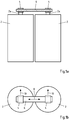
- Fig. 1a shows two battery cells 2, each with a pole 2a.
- a connection terminal 4 is welded to each pole.
- a flat part 6 is arranged in a clamping manner between the connection terminals 4 .
- a current flow between the two battery cells 2 takes place from one pole 2a, via a terminal 4, the flat part 6 and the respective other terminal 4 to the other pole 2a.
- Fig. 1b shows a top view of such an arrangement with the connection terminals 4 and the flat part 6.
- connection terminals 4 it must be ensured that the flat part 6 does not become detached from the connection terminals 4.
- the flat part expands or contracts in its longitudinal extent 8 due to thermal expansion. This "swelling" leads to a mechanical load on the connection terminals when the flat part 6 is firmly connected to the connection terminals 4 .
- the flat part 6 is clamped to the connection terminal with a degree of freedom along the longitudinal extension 8 so that the flat part 6 can move, expand and/or contract along its longitudinal extension 8 in the connection terminals 4 .
- the flat part 6 In a direction 10 perpendicular to the longitudinal extent 8 , the flat part 6 is held in the connection terminals 4 at least in a form-fitting manner. The flat part 6 can be removed from the connection terminal 4 in the direction 10 .
- a section parallel to the direction 10 through the flat part 6 show the Figures 2a-e .
- the flat part 6 has two wide surfaces 6a and two narrow surfaces 6b.
- a recess 12 or a projection 14 is provided on at least one broad surface 6a. This is in the Figures 2a and b shown.
- two recesses 12 and two projections 14 on a wide surface 6a may be provided. Also it is possible that both a recess 12 and a projection 14 is provided on a broad surface 6a, as in FIG Figure 2e shown.
- recesses 12 and/or projections 14 can also be provided on a wide surface 6a. Also, the recesses 12 and projections 14 may be arranged on the opposite broad surfaces 6a at the same time.
- a plan view of a flat part 6 shows the 3 . It can be seen that the recess 12 extends along the longitudinal extent 8 of the flat part 6 .
- Figures 4a to e show different terminals 16 to the respective flat parts 6 of Figures 2a-e correspond.
- a terminal 16 has a receiving area 18 and a connecting area 20.
- the receiving area 18 is formed by two legs 18a, 18b and a transition area 18c.
- the transition area 18c connects the two legs 18a, 18b to one another.
- the legs 18a, 18b have mating inner surfaces 18a', 18b'.
- the clear width 22 between the inner surfaces 18a', 18b' is preferably smaller than the extension of the flat part 6 along its narrow surface 6b.
- connection terminal 16 is formed from two different metal materials, with the receiving area 18, in particular the legs 18a, 18b and also the transition area 18c, being formed at least in parts from a first metal material and the connection area 20 being formed at least in parts from a second metal material.
- a joining zone 23 between the different metal materials can, as in the Figure 4a shown, at a transition between leg 18b and transition region 18c.
- a joining zone 23 can also be at the transition between the receiving area 18 and the connection area 20, as in FIG Figure 4b shown.
- a joining zone 23 in Area of the leg 18b are, as in FIG Figure 4c shown.
- the joining zone 23 can also be in an overlapping area, as in FIG Figure 4d shown.
- the joining zone is preferably arranged in such a way that it is free from mechanical loading due to the spring tension of the legs.
- the metal material from which at least one of the legs 18a and the transition region 18c is formed is preferably spring steel, whereas the metal material from which the connection region 20 is formed is well suited for a material connection to the terminal 2a of the battery cell 2.
- the transition area 18c has a curvature which is inclined in the direction of the opening 24 between the legs 18a, 18b.
- the bending radii between the legs 18a, b and the transition area 18c are opposite to the bending radius of the curvature of the transition area 18c.
- the transition region 18c can initially be bent in a direction pointing away from the leg 18b.
- the transition area 18c can then be bent in the direction of the leg 18b in a narrow bending radius.
- the transition region has an upwardly pointing "head" which protrudes from the upper plane of leg 18a.
- the transition area 18c can be arched in the direction of the opening 24 with a wide bending radius. Proceeding from this, the transition area 18c can again be bent in a narrow bending radius in the direction of the connection area 20 and can extend into the leg 18b.
- a particularly good clamping effect of the receiving area 18 is achieved by this multiple bending in the transition area.
- the flat part 6 is pushed into the opening 24 in the insertion direction 26 .
- the legs 18a, 18b are spread apart.
- the resulting restoring force leads to a spring force on the broad surfaces 6a of the flat part 6 so that it is clamped between the legs 18a, 18b.
- connection area 20 beyond the receiving area 18 .
- a normal projection of the legs 18a, 18b on one another shows that the connection area 20 is longer than the longest of the two legs 18a, 18b.
- the connection area there is a zone 28 at which an integral connection between the terminal 2a and the connection clamp 4 takes place.
- Figures 4b-e show a wide variety of terminals 4 for receiving the corresponding flat parts according to the Figures 2b-e are designed.
Description
Der Gegenstand betrifft einen Batteriezellenverbinder. Ein gegenständlicher Batteriezellenverbinder kann als Baugruppe gebildet sein und eingerichtet sein zum elektrisch leitenden Verbinden eines ersten Zellterminals einer ersten elektrochemischen Zelle einer elektrochemischen Vorrichtung mit einem zweiten Zellterminal einer zweiten elektrochemischen Zelle der elektrochemischen Vorrichtung. Eine elektrochemische Vorrichtung ist insbesondere eine Batterie, bevorzugt eine Kraftfahrzeugbatterie. Eine solche Batterie kann beispielsweise eine Batterie eines Antriebstrangs des Kraftfahrzeugs sein.The subject relates to a battery cell connector. A physical battery cell connector can be formed as an assembly and set up to electrically conductively connect a first cell terminal of a first electrochemical cell of an electrochemical device to a second cell terminal of a second electrochemical cell of the electrochemical device. An electrochemical device is in particular a battery, preferably a motor vehicle battery. Such a battery can be, for example, a battery of a drive train of the motor vehicle.
In rein batteriebetriebenen elektrischen Fahrzeugen (BEV) als auch in Plug-in-Hybrid elektrischen Fahrzeugen (PHEV), insbesondere Automobilen, Zweirädern, Schiffen, Luftschiffen und dergleichen, kommen vermehrt Batterien zum Einsatz, bei denen eine Vielzahl an elektrochemischen Zellen miteinander in Reihe und/oder parallel zueinander geschaltet werden. Jede einzelne Zelle weist eine an und für sich geringe Speicherkapazität als auch eine geringe Zellspannung, beispielsweise von 4,8 V auf. Durch das Zusammenschalten mehrerer Zellen können aber hohe Batteriekapazitäten bei gleichzeitig hohen Spannungen realisiert werden. Batteriezellen können beispielsweise Lithium-Ionen-Batteriezellen sein.In purely battery-operated electric vehicles (BEV) as well as in plug-in hybrid electric vehicles (PHEV), in particular automobiles, two-wheelers, ships, airships and the like, batteries are increasingly being used in which a large number of electrochemical cells are connected in series with one another /or be connected in parallel to each other. Each individual cell has an intrinsically low storage capacity and a low cell voltage, for example 4.8V. By connecting several cells together, however, high battery capacities can be achieved with high voltages at the same time. Battery cells can be lithium-ion battery cells, for example.
Aufgrund der hohen Stromflüsse in Fahrzeugen, beispielsweise bei der Verwendung von Batterien als Energiespeicher für den Antriebsstrang, ist es notwendig, die Batteriezellen untereinander mit geringen Übergangswiderständen zu verbinden. Hierzu eignen sich insbesondere sogenannte Batteriezellenverbinder, die an sich bekannt sind. Die Batteriezellenverbinder werden in der Regel an die Pole der Zellterminals angeschweißt, so dass eine stoffschlüssige Verbindung gebildet ist. Über diese stoffschlüssige Verbindung fließt der Strom zwischen den einzelnen Zellen. Die stoffschlüssige Verbindung bietet einen geringen Übergangswiderstand, hat jedoch den Nachteil, dass sie gegenüber mechanischen Belastungen instabil sein kann, insbesondere bei Vibrationen und dauerhaften mechanischen Belastungen brechen kann.Due to the high current flows in vehicles, for example when using batteries as energy storage for the drive train, it is necessary to connect the battery cells to each other with low contact resistance. So-called battery cell connectors, which are known per se, are particularly suitable for this purpose. The battery cell connectors are usually welded to the poles of the cell terminals, so that an integral connection is formed. The current flows between the individual cells via this material connection. The material connection offers a low transition resistance, but has the disadvantage that it can be unstable to mechanical loads, in particular it can break under vibration and permanent mechanical loads.
Insbesondere in Anwendungen, in denen die Umweltbedingungen stark schwanken können oder in denen sich die Batterien stark aufheizen, kann es zum sogenannten "swelling" kommen. Das Swelling kann auch aufgrund altersbedingter Veränderung der Materialstruktur oder Dimensionen der Zellen relevant sein. Bei diesem Phänomen kommt es z.B. aufgrund von Temperaturschwankungen zu Längenänderungen des Zellverbinders und/oder der Zellterminals. Ein Zellverbinder ist in der Regel ein Flachteil, welches zwischen den Terminals der Batteriezellen angeordnet ist. Die durch die Temperaturveränderung bewirkte Längenänderung des Flachteils führt zu einer mechanischen Belastung der Verbindung des Flachteils mit dem Batterieterminal, welche im ungünstigsten Fall zu einem Bruch der elektrischen Verbindung führen kann.So-called "swelling" can occur particularly in applications in which the environmental conditions can vary greatly or in which the batteries heat up considerably. Swelling can also be relevant due to age-related changes in the material structure or dimensions of the cells. This phenomenon results in changes in the length of the cell connector and/or the cell terminals, e.g. due to temperature fluctuations. A cell connector is usually a flat part that is arranged between the terminals of the battery cells. The change in length of the flat part caused by the temperature change leads to mechanical stress on the connection of the flat part to the battery terminal, which in the worst case can lead to a break in the electrical connection.
Um die mechanische Belastung durch das Swelling zu verringern, sind Zellverbinder bekannt, bei denen das Flachteil, auch BusBar genannt, zwischen zwei jeweils an einem Terminal der Batterieklemme angeordneten Klammern angeordnet ist. So ist beispielsweise aus der
Die aus dem Stand der Technik bekannte Baugruppe weist jedoch den Nachteil auf, dass die Haltekraft des Zellverbinders in dem Kontaktelement über eine hierfür eingerichtete Haltevorrichtung aufgebracht werden muss. Die Haltevorrichtung ist einerseits komplex in der Herstellung und andererseits fehleranfällig.However, the assembly known from the prior art has the disadvantage that the holding force of the cell connector in the contact element has to be applied via a holding device set up for this purpose. On the one hand, the holding device is complex to manufacture and, on the other hand, is prone to errors.
Aus diesem Grunde lag dem Gegenstand die Aufgabe zugrunde, einen Zellverbinder zur Verfügung zu stellen, bei dem die Haltevorrichtung als Anschlussklemme gebildet ist und in ihren mechanischen Eigenschaften optimiert ist.For this reason, the object on which the object was based was to provide a cell connector in which the holding device is designed as a connection terminal and its mechanical properties are optimized.
Gegenständlich ist erkannt worden, dass die Anschlussklemme zwei Bedingungen erfüllen muss. Einerseits muss die Anschlussklemme dazu geeignet sein, das Flachteil, welches zum Verbinden der Zellen eingesetzt wird, klemmend zu halten und andererseits muss ein guter elektrischer Kontakt mit dem Flachteil auf der einen Seite und dem Terminal der Batteriezelle auf der anderen Seite gewährleistet werden. Die Haltekraft wird insbesondere über eine Federkraft auf das Flachteil ausgeübt. Diese Federkraft bedingt andere Materialeigenschaften als diese, die erforderlich sind, um die Anschlussklemme mit einem Pol oder Terminal einer Batteriezelle zu verbinden. Aus diesem Grunde wird vorgeschlagen, dass die Anschlussklemme bimetallisch ist, wobei ein Anschlussbereich aus einem ersten Metallwerkstoff gebildet ist und ein Aufnahmebereich zumindest teilweise aus einem zweiten, von dem ersten Metallwerkstoff verschiedenen Metallwerkstoff, gebildet ist.Objectively, it has been recognized that the connection terminal must meet two conditions. On the one hand, the connection clamp must be suitable for holding the flat part, which is used to connect the cells, and on the other hand, good electrical contact must be ensured with the flat part on one side and the terminal of the battery cell on the other side. The holding force is exerted on the flat part in particular by means of a spring force. This spring force requires different material properties than those required to connect the connection clamp to a pole or terminal of a battery cell. For this reason, it is proposed that the connection terminal be bimetallic, with a connection area being formed from a first metal material and a receiving area being formed at least partially from a second metal material that is different from the first metal material.
Der Gegenständliche Zellenverbinder samt Anschlussklemme zeichnet sich durch ein geringes Gewicht, guten Leitwert, einen geringen und stabilen Übergangswiderstand aus. Ferner ist der Zellenverbinder zerstörungsfrei demontierbar. Der Fertigungsaufwand ist gering. Die Fertigung kann vollautomatisch erfolgen. Auf die Montage kann vollautomatisch erfolgen.The cell connector in question, including the connection terminal, is characterized by its low weight, good conductance, and low and stable contact resistance. Furthermore, the cell connector can be dismantled without destroying it. The manufacturing cost is low. The production can be fully automatic. On the assembly can be done fully automatically.
Durch die Ausgestaltung der Anschlussklemme aus unterschiedlichen Metallwerkstoffen wird der Effekt erzielt, dass die Anschlussklemme Bereichsweise an die verschiedenen Anforderungen, die an sie gestellt wird, angepasst ist. Zum einen kann ein Metallwerkstoff eines ersten Bereichs derart gewählt werden, dass er zum klemmenden Halten des Flachteils geeignet ist. Das klemmende Halten erfordert einen Metallwerkstoff, der besonders gute Federeigenschaften hat. Der hierfür notwendige Metallwerkstoff ist aber nicht geeignet, eine sortenreine Verbindung zu einem Terminal einer Zelle zu bilden und/oder gut stoffschlüssig mit dem Terminal der Klemme verbunden zu werden.By configuring the connection terminal from different metal materials, the effect is achieved that the connection terminal is adapted in areas to the different requirements placed on it. On the one hand, a metal material of a first area can be selected in such a way that it is suitable for holding the flat part in a clamped manner. Holding by clamping requires a metal material that has particularly good spring properties. However, the metal material required for this is not suitable for a single-variety connection to a To form the terminal of a cell and/or to be firmly bonded to the terminal of the clamp.
Der andere Metallwerkstoff des weiteren Bereichs kann so gewählt sein, dass er besonders gut mit dem Metallwerkstoff des Terminals/Pols der Batteriezelle kombinierbar und verbindbar ist, insbesondere zur Vermeidung von Kontaktkorrosion. Bei der Verbindung zwischen der Anschlussklemme und dem Terminal der Batteriezelle ist bevorzugt ein sortenreiner Übergang angestrebt. Der hierfür notwendige Metallwerkstoff ist aber nicht geeignet, eine gute Klemmkraft auf das Flachteil auszuüben.The other metal material of the further area can be selected in such a way that it can be combined and connected particularly well with the metal material of the terminal/pole of the battery cell, in particular to avoid contact corrosion. In the case of the connection between the connecting clamp and the terminal of the battery cell, a homogeneous transition is preferably sought. However, the metal material required for this is not suitable for exerting a good clamping force on the flat part.
Die Bereiche können ein Anschlussbereich und ein Aufnahmebereich sein. Die Bereiche können entlang der Längsachse des Flachteils aneinander angrenzen. Der Anschlussbereich kann an einem ersten Ende des Flachteils liegen und der Aufnahmebereich an einem diesem gegenüberliegenden Ende des Flachteils.The areas can be a connection area and a recording area. The areas can adjoin one another along the longitudinal axis of the flat part. The connection area can be on a first end of the flat part and the receiving area on an opposite end of the flat part.
Es wird vorgeschlagen, dass der Aufnahmebereich aus einem Metallwerkstoff gebildet ist, dessen Verhältnis von Streckgrenze zur Zugfestigkeit über 70%, vorteilhafterweise über 85% liegt.It is proposed that the receiving area is formed from a metal material whose ratio of yield point to tensile strength is over 70%, advantageously over 85%.
Die Streckgrenze kann der ReL- oder ReH-Wert sein, die Zugfestigkeit kann der Rm-Wert sein. Alle Werte können nach ISO 6892, DIN 50154, ASTME E8 oder ASTM E21 gemessen werden. Die Probengeometrie für die Werkstoffe ergibt sich nach DIN 50125. Durch das geforderte Verhältnis von Streckgrenze zu Zugfestigkeit wird eine gute Federelastizität im Aufnahmebereich erreicht, so dass der Aufnahmebereich das Flachteil besonders gut klemmend aufnehmen kann.The yield strength can be the R eL or R eH value, the tensile strength can be the R m value. All values can be measured according to ISO 6892, DIN 50154, ASTME E8 or ASTM E21. The sample geometry for the materials results from DIN 50125. The required ratio of yield point to tensile strength achieves good spring elasticity in the receiving area, so that the receiving area can receive the flat part in a particularly good clamping manner.
Gemäß einem Ausführungsbeispiel wird vorgeschlagen, dass der Aufnahmebereich aus seinem Federstahl gebildet ist. Hier eignen sich insbesondere Federstähle nach DIN EN 10089, DIN EN 10092, DIN EN 10132 oder DIN EN 10151, insbesondere X10CrNi18-8, 38Si7, 52CrMoV4, 51CrV4, oder 61SiCr7, C67E / C67S.According to one exemplary embodiment, it is proposed that the receiving area be formed from its spring steel. Spring steels according to DIN EN 10089, DIN EN 10092, DIN EN 10132 or DIN EN 10151 are particularly suitable here, in particular X10CrNi18-8, 38Si7, 52CrMoV4, 51CrV4, or 61SiCr7, C67E / C67S.
Der Aufnahmebereich hat besondere mechanische Anforderungen, insbesondere hinsichtlich seiner auf das Flachteil ausgeübten Klemmkraft. Dagegen hat der Anschlussbereich insbesondere Anforderungen an die Verbindbarkeit mit dem Terminal der Batteriezelle. Aus diesem Grunde muss die Anschlussklemme einen Übergang zwischen dem Aufnahmebereich und dem Anschlussbereich aufweisen, um die unterschiedlichen Metallwerkstoffe bereitzustellen. Es wird vorgeschlagen, dass der Aufnahmebereich mit dem Anschlussbereich stirnseitig überlappend verbunden ist. Auch ist es möglich, dass der Aufnahmebereich mit dem Anschlussbereich stirnseitig stumpf verbunden ist. Insbesondere ein stumpfer Stoß zwischen zwei Flachteilen, die einerseits den Anschlussbereich und andererseits den Aufnahmebereich bilden, ist bevorzugt.The receiving area has special mechanical requirements, in particular with regard to the clamping force exerted on the flat part. In contrast, the connection area has particular requirements for connectivity with the terminal of the battery cell. For this reason, the connection terminal must have a transition between the receiving area and the connection area in order to provide the different metal materials. It is proposed that the receiving area is connected to the connection area in an overlapping manner at the end. It is also possible for the receiving area to be butt-connected to the connection area on the front side. In particular, a butt joint between two flat parts, which form the connection area on the one hand and the receiving area on the other hand, is preferred.
Eine besonders gute Leitfähigkeit der Anschlussklemme wird dadurch erreicht, dass der Aufnahmebereich stoffschlüssig mit dem Anschlussbereich verbunden ist. Dafür eignen sich insbesondere Reibschweißverfahren, hier insbesondere ein Ultraschallschweißverfahren. Bevorzugt ist ein Rührreibschweißen als auch ein Ultraschallrollnahtschweißen.A particularly good conductivity of the connection terminal is achieved in that the receiving area is materially connected to the connection area. Friction welding processes are particularly suitable for this, here in particular an ultrasonic welding process. Friction stir welding and also ultrasonic roller seam welding are preferred.
Das Flachteil wird von dem Aufnahmebereich klemmend aufgenommen. Um eine möglichst große Kontaktfläche gewährleisten zu können, wird vorgeschlagen, dass der Aufnahmebereich und der Anschlussbereich jeweils aus einem flachen Metallteil gebildet sind. Hierdurch wird das Flachteil flächig von dem Aufnahmebereich aufgenommen und der Anschlussbereich kann flächig mit einem Terminal der Batteriezelle verbunden werden.The flat part is received in a clamping manner by the receiving area. In order to be able to ensure the largest possible contact surface, it is proposed that the receiving area and the connection area are each formed from a flat metal part. As a result, the flat part is held flat by the receiving area and the connection area can be connected flat to a terminal of the battery cell.
Um eine ausreichend große Klemmkraft auf das Flachteil ausüben zu können, wird vorgeschlagen, dass das Flachteil klemmend in dem Aufnahmebereich aufgenommen wird. Um eine gute Klemmwirkung zu erzielen, wird vorgeschlagen, dass der Aufnahmebereich aus zwei gegenüberliegenden Schenkeln gebildet ist. Die Schenkel bilden bevorzugt ein U, wobei die lichte Weite zwischen den Schenkel geringer ist, als eine Materialstärke des Flachteils. Dies führt zu einer Presspassung zwischen den Schenkeln und dem Flachteil, so dass das Flachteil in seiner montierten Position die Schenkel auseinanderdrückt. Die hierdurch bewirkte Rückstellkraft der Schenkel verursacht das Verklemmen des Flachteils zwischen den Schenkeln.In order to be able to exert a sufficiently large clamping force on the flat part, it is proposed that the flat part be clamped in the receiving area. In order to achieve a good clamping effect, it is proposed that the receiving area be formed from two opposing legs. The legs preferably form a U, with the clear width between the legs being less than a material thickness of the flat part. This results in an interference fit between the legs and the flat part, so that the flat part forces the legs apart in its assembled position. The resultant restoring force of the legs causes the flat part to jam between the legs.
Zwischen den Schenkeln ist ein Übergangsbereich vorgesehen, der insbesondere in etwa kreisförmig, bevorzugt halbkreisförmig, gebildet ist. Der Übergangsbereich verbindet die einander gegenüberliegenden Schenkel miteinander. In ihrer Längserstreckung überkreuzen sich die Schenkel nicht, so dass die Schenkel auf der dem Übergangsbereich gegenüberliegenden Seite eine Öffnung aufspannen. In diese Öffnung kann das Flachteil eingeschoben werden.A transition region is provided between the legs, which is formed in particular in an approximately circular, preferably semicircular, manner. The transition area connects the opposing legs to one another. The legs do not cross over one another in their longitudinal extent, so that the legs open up an opening on the side opposite the transition area. The flat part can be pushed into this opening.
Für eine gute elektrische Leitfähigkeit einerseits, andererseits jedoch geringes Gewicht, wird vorgeschlagen, dass das Flachteil aus einem Aluminiumwerkstoff oder einem beschichteten Aluminiumwerkstoff insbesondere mit einem Kupferwerkstoff beschichteten Aluminiumwerkstoff gebildet ist. Auf der anderen Seite ist es auch möglich, beispielsweise wenn die Anschlussklemme teilweise aus Aluminium gebildet ist, dass das Flachteil aus einem Kupferwerkstoff oder einem beschichteten Kupferwerkstoff, insbesondere mit einem Aluminiumwerkstoff beschichteten Kupferwerkstoff gebildet ist.For good electrical conductivity on the one hand, but on the other hand low weight, it is proposed that the flat part be formed from an aluminum material or a coated aluminum material, in particular with an aluminum material coated with a copper material. On the other hand, it is also possible, for example if the connection terminal is partially made of aluminum, for the flat part to be made of a copper material or a coated copper material, in particular copper material coated with an aluminum material.
Die beiden Schenkel mit dem Übergangsbereich spannen U-förmig den Aufnahmebereich auf. Dabei weisen jeweils innere Oberflächen der Schenkel zueinander. Zumindest eine der inneren Oberflächen der Schenkel hat eine zu dem Flachteil komplementäre, profilierte Oberfläche, so dass insbesondere die innere Oberfläche mit einer Oberfläche des Flachteils nut- und federartig ineinander greift. Dabei kann die innere Oberfläche zumindest einen Vorsprung und/oder eine Ausnehmung aufweisen und das Flachteil jeweils hierzu korrespondierend zumindest eine Ausnehmung und/oder einen Vorsprung. Hierdurch greifen montierten Zustand Flachteil und innere Oberfläche nut- und federartig ineinander.The two legs with the transition area span the receiving area in a U-shape. In this case, inner surfaces of the legs face each other. At least one of the inner surfaces of the legs has a profiled surface complementary to the flat part, so that in particular the inner surface engages with a surface of the flat part like a tongue and groove. The inner surface can have at least one projection and/or one recess and the flat part can have at least one recess and/or one projection corresponding thereto. As a result, in the mounted state, the flat part and the inner surface engage in one another like a tongue and groove.
Auch wird vorgeschlagen, dass zumindest eine innere Oberfläche oder eine an der inneren Oberfläche anliegende Oberfläche des Flachteils zumindest einen Vorsprung aufweist und die jeweils gegenüberliegende innere Oberfläche oder Oberfläche des Flachteils zumindest eine hierzu korrespondierende Aufnahme aufweist.It is also proposed that at least one inner surface or a surface of the flat part lying against the inner surface has at least one projection and the respectively opposite inner surface or surface of the flat part has at least one corresponding receptacle.
Gemäß einem Ausführungsbeispiel wird vorgeschlagen, dass der Vorsprung und die Aufnahme eine Längserstreckung aufweisen, welche quer, vorzugsweise senkrecht zur Längserstreckung der Schenkel und/oder parallel zur Längserstreckung des Flachteils verläuft. Hierdurch wird im montierten Zustand sichergestellt, dass Vorsprung und Aufnahme quer zur Einschubrichtung des Flachteils in die Öffnung zwischen den Schenkeln ineinandergreifen.According to one exemplary embodiment, it is proposed that the projection and the receptacle have a longitudinal extent that runs transversely, preferably perpendicularly, to the longitudinal extent of the legs and/or parallel to the longitudinal extent of the flat part. In the assembled state, this ensures that the projection and receptacle engage in one another transversely to the direction of insertion of the flat part into the opening between the legs.
Für eine gut leitende Verbindung des Batteriezellenverbinders mit einem Terminal einer Zelle, wird vorgeschlagen, dass der Anschlussbereich stoffschlüssig mit dem zu kontaktierenden Terminal (Pol) einer Zelle verbunden ist, insbesondere mittels Laserschweißen oder Ultraschallschweißen, bevorzugt torsionalem Ultraschallschweißen. Sowohl beim Laserschweißen, als auch beim Ultraschallschweißen wird die Schweißenergie sehr gezielt in den Schweißknoten eingeleitet. Die den Schweißknoten umgebende Bereiche werden nicht somit nur wenig erhitzt. Hierdurch wird verhindert, dass die elektrochemische Zelle in der Batteriezelle beschädigt wird.For a good conductive connection of the battery cell connector to a terminal of a cell, it is proposed that the connection area is materially connected to the terminal (pole) of a cell to be contacted, in particular by means of laser welding or ultrasonic welding, preferably torsional ultrasonic welding. Both with laser welding and with ultrasonic welding, the welding energy is introduced into the welding node in a very targeted manner. The areas surrounding the weld node are therefore only slightly heated. This prevents the electrochemical cell in the battery cell from being damaged.
Für eine besonders gute formschlüssige Verbindung zwischen Flachteil und den Schenkeln des Anschlussteils im verbundenen Zustand wird vorgeschlagen, dass zumindest zwei zueinander parallel verlaufende Vorsprünge und Aufnahmen an den aneinander anliegenden Oberflächen von Flachteil und Schenkel angeordnet sind. Das Flachteil ist bevorzugt nur an einer Oberfläche mit Vorsprung oder Aufnahme versehen, die gegenüberliegende Oberfläche ist bevorzugt plan.For a particularly good form-fitting connection between the flat part and the legs of the connecting part in the connected state, it is proposed that at least two projections and receptacles running parallel to one another be arranged on the surfaces of the flat part and leg that rest against one another. The flat part is preferably only provided with a projection or receptacle on one surface, the opposite surface is preferably flat.
Gemäß einem Ausführungsbeispiel wird vorgeschlagen, dass zumindest zwei im montierten Zustand an einander anliegenden Oberflächen von Flachteil und Schenkel komplementär zueinander verlaufende Vorsprünge und Aufnahmen aufweisen, und dass die Vorsprünge und Aufnahmen quer zu einer Längserstreckung der Schenkel ineinander greifen. Dies führt zu einem guten Formschluss zwischen den Schenkeln und dem Flachteil, so dass im montierten Zustand eine hohe Auszugskraft notwendig ist, um das Flachteil aus der Öffnung zwischen den Schenkeln herauszulösen.According to one exemplary embodiment, it is proposed that at least two surfaces of the flat part and leg that abut one another in the assembled state have mutually complementary projections and receptacles, and that the projections and receptacles engage transversely to a longitudinal extension of the legs. This leads to a good form fit between the legs and the flat part, so that in the assembled state a high pull-out force is required to detach the flat part from the opening between the legs.
Die Fügezone zwischen dem Anschlussbereich und dem Terminal der Zelle ist bevorzugt entfernt von dem Bereich, in dem die Anschlussklemme mechanisch belastet wird. Daher wird vorgeschlagen, dass eine Fügezone zwischen dem Werkstoff des Anschlussbereichs und dem Werkstoffs des Aufnahmebereichs im Bereich zumindest eines Schenkels oder im Übergangsbereich liegt. Die Anschlussklemme wird im Aufnahmebereich durch das Klemmen des Flachteils mechanisch belastet, insbesondere gedehnt und/oder gestaucht und/oder tordiert wird. Die damit einhergehende mechanische Verformung kann sich negativ auf die Verbindung zwischen der Anschlussklemme und dem Terminal im Anschlussbereich auswirken. Insbesondere können mechanische Zug- und/oder Druckkräfte dazu führen, dass sich die Verbindung mit der Zeit löst. Dies könnte zu einer Unterbrechung der elektrischen Verbindung führen und die Batterie wäre ggf. nicht mehr nutzbar.The joining zone between the connection area and the terminal of the cell is preferably remote from the area in which the connection terminal is subjected to mechanical stress. It is therefore proposed that a joining zone between the material of the connecting area and the material of the receiving area is located in the area of at least one leg or in the transition area. The connection terminal is mechanically stressed in the receiving area by the clamping of the flat part, in particular it is stretched and/or compressed and/or twisted. The associated mechanical deformation can have a negative effect on the connection between the connection clamp and the terminal in the connection area. In particular, mechanical tensile and/or compressive forces can cause the connection to become loose over time. This could lead to an interruption in the electrical connection and the battery might no longer be usable.
Gemäß einem Ausführungsbeispiel wird vorgeschlagen, dass der Anschlussbereich mit dem Terminal der Zelle entfernt von der Fügezone im Aufnahmebereich verbunden ist. Dies führt dazu, dass die Kraft, die beim Fügen des Flachteils in die Öffnung des Aufnahmebereichs eingeleitet wird, nicht in den Anschlussbereich und insbesondere den Bereich, in dem der Anschlussbereich mit dem Terminal der Zelle verbunden ist, eingekoppelt wird.According to one embodiment, it is proposed that the connection area is connected to the terminal of the cell remote from the joining zone in the receiving area. As a result, the force that is introduced into the opening of the receiving area when the flat part is joined is not coupled into the connection area and in particular the area in which the connection area is connected to the terminal of the cell.
Die Anschlussklemme ist in einem Längsschnitt bevorzugt hakenförmig. Bevorzugt ist der Anschlussbereich in seiner Längserstreckung über eine Normalprojektion der inneren Oberfläche eines Schenkels auf den Anschlussbereich hinaus ragend. Das bedeutet, dass der Anschlussbereich in seiner Längserstreckung über die Längserstreckung der Schenkel des Aufnahmebereichs hinaus geht. Die Verbindung mit dem Terminal der Zelle liegt außerhalb der durch die Schenkel aufgespannten Fläche.The connection terminal is preferably hook-shaped in a longitudinal section. In its longitudinal extent, the connection area preferably projects beyond a normal projection of the inner surface of a leg onto the connection area. This means that the length of the connection area goes beyond the length of the legs of the receiving area. The connection with the terminal of the cell lying outside the area spanned by the limbs.
Gemäß einem Ausführungsbeispiel wird vorgeschlagen, dass die Längserstreckung des Anschlussbereichs mit dem damit verbundenen ersten Schenkel des Aufnahmebereichs größer ist, als die Längserstreckung des zweiten Schenkels des Aufnahmebereichs.According to one exemplary embodiment, it is proposed that the longitudinal extension of the connection area with the first leg of the receiving area connected thereto is greater than the longitudinal extension of the second leg of the receiving area.
Der Aufnahmebereich kann durch einen Schenkel und Teile des Anschlussbereichs gebildet sein. Über den Übergangsbereich ist der zweite Schenkel des Aufnahmebereichs mit dem ersten Schenkel verbunden. Ausgehend von dem ersten Schenkel erstreckt sich auf der gegenüberliegenden Seite des Übergangsbereichs der Anschlussbereich.The receiving area can be formed by a leg and parts of the connection area. The second leg of the receiving area is connected to the first leg via the transition area. Starting from the first leg, the connection area extends on the opposite side of the transition area.
Nachfolgend wird der Gegenstand anhand einer Ausführungsbeispiele zeigenden Zeichnung näher erläutert. In der Zeichnung zeigen:
- Fig. 1a
- eine Seitenansicht eines Batteriezellenverbinders mit Batteriezellen;
- Fig. 1b
- eine Draufsicht auf einen Batteriezellenverbinders mit Batteriezellen;
- Fig. 2a-e
- verschiedene Querschnitte eines Flachteils;
- Fig. 3
- eine Draufsicht auf ein Flachteil;
- Fig. 4a-e
- Längsschnitte einer Anschlussklemme korrespondierend zu den
Flachteilen gemäß Figuren 2a-e ; - Fig. 5
- eine Draufsicht auf eine Anschlussklemme.
- Fig. 1a
- a side view of a battery cell connector with battery cells;
- Fig. 1b
- a plan view of a battery cell connector with battery cells;
- Fig. 2a-e
- different cross-sections of a flat part;
- 3
- a plan view of a flat part;
- Fig. 4a-e
- Longitudinal sections of a terminal corresponding to the flat parts according to
Figures 2a-e ; - figure 5
- a plan view of a terminal.
Im Betrieb ist sicherzustellen, dass das Flachteil 6 sich nicht von den Anschlussklemmen 4 löst. Andererseits kommt es im Betrieb jedoch dazu, dass sich das Flachteil in seiner Längserstreckung 8 durch Wärmeausdehnung ausdehnt oder zusammenzieht. Dieses "swelling" führt zu einer mechanischen Belastung der Anschlussklemmen, wenn das Flachteil 6 fest mit den Anschlussklemmen 4 verbunden ist.During operation, it must be ensured that the
Gegenständlich wird das Flachteil 6 jedoch mit einem Freiheitsgrad entlang der Längserstreckung 8 an der Anschlussklemme klemmend befestigt, so dass sich das Flachteil 6 entlang seiner Längserstreckung 8 in den Anschlussklemmen 4 bewegen, ausdehnen und/oder zusammenziehen kann. In einer Richtung 10 senkrecht zur Längserstreckung 8 ist das Flachteil 6 dabei aber zumindest formschlüssig in den Anschlussklemmen 4 gehalten. In der Richtung 10 kann das Flachteil 6 aus der Anschlussklemme 4 entfernt werden.In the present case, however, the
Ein Schnitt parallel zur Richtung 10 durch das Flachteil 6 zeigen die
Auch können zwei Ausnehmungen 12 bzw. zwei Vorsprünge 14 an einer breiten Oberfläche 6a, wie in den
Es versteht sich, dass auch mehr als zwei Ausnehmungen 12 und/oder Vorsprünge 14 auf einer breiten Oberfläche 6a vorgesehen sein können. Auch können die Ausnehmungen 12 und Vorsprünge 14 auf den gegenüberliegenden breiten Oberflächen 6a gleichzeitig angeordnet sein.It goes without saying that more than two
Eine Draufsicht auf ein Flachteil 6 zeigt die
Die
Eine Anschlussklemme 16 hat dabei einen Aufnahmebereich 18 als auch einen Anschlussbereich 20. Der Aufnahmebereich 18 ist durch zwei Schenkel 18a, 18b sowie einem Übergangsbereich 18c gebildet. Der Übergangsbereich 18c verbindet die beiden Schenkel 18a, 18b miteinander. Die Schenkel 18a, 18b haben einander zugewiesene innere Oberflächen 18a', 18b'. Die lichte Weite 22 zwischen den inneren Oberflächen 18a', 18b' ist bevorzugt kleiner als die Erstreckung des Flachteils 6 entlang seiner schmalen Oberfläche 6b.A terminal 16 has a receiving
Die Anschlussklemme 16 ist aus zwei unterschiedlichen Metallwerkstoffen gebildet, wobei der Aufnahmebereich 18, insbesondere die Schenkel 18a, 18b als auch der Übergangsbereich 18c zumindest in Teilen aus einem ersten Metallwerkstoff gebildet sind und der Anschlussbereich 20 zumindest in Teilen aus einem zweiten metallischen Metallwerkstoff gebildet ist. Eine Fügezone 23 zwischen den verschiedenen Metallwerkstoffen kann, wie in der
Der Metallwerkstoff, aus dem zumindest einer der Schenkel 18a und der Übergangsbereich 18c gebildet ist, ist bevorzugt ein Federstahl, wohingegen der Metallwerkstoff, aus dem der Anschlussbereich 20 gebildet ist, sich gut für eine stoffschlüssige Verbindung mit dem Terminal 2a der Batteriezelle 2 eignet.The metal material from which at least one of the
Zu Erzielung einer guten Klemmkraft auf das Flachteil 6 hat der Übergangsbereich 18c eine in Richtung der Öffnung 24 zwischen den Schenkeln 18a, 18b geneigte Wölbung. Die Biegeradien zwischen den Schenkeln 18a, b und dem Übergangsbereich 18c sind entgegengesetzt zum Biegeradius der Wölbung des Übergangsbereichs 18c. Ausgehend von dem Schenkel 18a kann der Übergangsbereich 18c zunächst in einer Richtung von dem Schenkel 18b wegweisend gebogen sein sein. In einem engen Biegeradius kann der Übergangsbereich 18c dann in Richtung des Schenkels 18b gebogen sein. Somit hat der Übergangsbereich einen nach oben weisenden "Kopf", welcher aus der oberen Ebene des Schenkels 18a heraus ragt.In order to achieve a good clamping force on the
Im Anschluss kann der Übergangsbereich 18c in einem weiten Biegeradius in Richtung der Öffnung 24 gewölbt sein. Ausgehend hiervon kann der Übergangsbereich 18c wieder in einem engen Biegeradius in Richtung des Anschlussbereichs 20 gebogen sein und sich in den Schenkel 18b erstrecken.Subsequently, the
Durch diese Mehrfachbiegung im Übergangsbereich wird eine besonders gute Klemmwirkung des Aufnahmebereichs 18 erreicht.A particularly good clamping effect of the receiving
Zur Montage wird das Flachteil 6 in Einschubrichtung 26 in die Öffnung 24 eingeschoben. Dabei werden die Schenkel 18a, 18b auseinander gespreizt. Die dadurch bewirkte Rückstellkraft führt zu einer Federkraft auf die breiten Oberflächen 6a des Flachteils 6, so dass dieses klemmend zwischen den Schenkeln 18a, 18b gehalten ist.For assembly, the
Durch diese mechanische Spannung kommt es zu einer mechanischen Belastung der Schenkel 18a, 18b. Es muss vermieden werden, dass diese mechanische Belastung auf die stoffschlüssige Verbindung zwischen dem Pol 2a und dem Anschlussbereich 20 ausstrahlt. Aus diesem Grunde ragt, wie in der
Die
- 22
- Batteriezellebattery cell
- 2a2a
- Terminalterminal
- 44
- Anschlussklemmeterminal block
- 66
- Flachteilflat part
- 6a6a
- breite Oberflächewide surface
- 6b6b
- schmale Oberflächenarrow surface
- 88th
- Längserstreckunglongitudinal extent
- 1010
- Querrichtungtransverse direction
- 1212
- Ausnehmungrecess
- 1414
- Vorsprunghead Start
- 1818
- Aufnahmebereichrecording area
- 18a,b18a,b
- Schenkelleg
- 18c18c
- Übergangsbereichtransition area
- 2020
- Anschlussbereichconnection area
- 2222
- lichte Weiteclear expanse
- 2323
- Fügezonejoining zone
- 2424
- Öffnungopening
- 2626
- Einschubrichtunginsertion direction
Claims (15)
- Battery cell connector with- at least two terminal clamps (4), each with a receiving area (18) and a connection area (20), and- at least one flat part (6), wherein- the receiving area (18) of at least one of the terminal clamps (4) is arranged to clampingly receive the flat part (6), and the connection area (20) of at least one of the terminal clamps (4) is arranged to connect to be materially bonded to one pole of a battery cell,
characterized in that,- the terminal clamp (4) is bimetallic, wherein the connection area (20) is formed at least partially from a first metal material and the receiving area (18) is formed at least partially from a second metal material different from the first metal material. - Battery cell connector according to claim 1,
characterized in that,- the receiving area (18) is at least partially formed from a metallic material whose ratio of yield strength to tensile strength is above 70%, advantageously above 85% and/or- the receiving area (18) is at least partially formed from a spring steel, in particular according to DIN EN 10089, DIN EN 10092, DIN EN 10132 or DIN EN 10151, in particular from X10CrNi18-8, 38Si7, 52CrMoV4, 51CrV4, or 61SiCr7, C67E / C67S. - Battery cell connector according to one of the preceding claims,
characterized in that,- the receiving area is connected to the connection area with an overlap, or that the receiving area is butt-jointed to the connection area at the front end. - Battery cell connector according to one of the preceding claims,
characterized in that,- the receiving area is joined to the connection area in a material bond, in particular by means of friction welding, preferably friction stir welding, ultrasonic welding, preferably ultrasonic roll seam welding. - Battery cell connector according to one of the preceding claims,
characterized in that,- the receiving area and the connection area are each formed from a flat metal part and/or- the receiving area is formed by two opposing legs, the clear span between the legs being less than a material thickness of the flat part. - Battery cell connector according to one of the preceding claims,
characterized in that,- in that the receiving area is formed from two opposing legs and a transition area connecting the legs to each other, the transition area being opposite an opening spanned by the legs. - Battery cell connector according to one of the preceding claims,
characterized in that,- the flat part (6) is formed from an aluminium material or a coated aluminium material, in particular aluminium material coated with a copper material, or the flat part (6) is formed from a copper material or a coated copper material, in particular a copper material coated with an aluminium material. - Battery cell connector according to one of the preceding claims,
characterized in that,- the legs (18a,b) each have an inner surface which faces towards the other leg, wherein in particular at least one inner surface engaging with the flat part (6) in a tongue-and-groove fashion. - Battery cell connector according to one of the preceding claims,
characterized in that,- at least one inner surface or a surface of the flat part (6) lying against the inner surface has a projection (14) and the respective opposite inner surface or surface of the flat part (6) has a recess corresponding thereto and/or- the projection (14) and the recess have a longitudinal extent (8) which is transverse, preferably perpendicular to the longitudinal extent (8) of the legs (18a,b) and/or parallel to the longitudinal extent (8) of the flat part (6). - Battery cell connector according to one of the preceding claims,
characterized in that,- the connection area (20) is connected to the pole of a cell to be contacted in a material bond, in particular by means of laser welding or ultrasonic welding, preferably by torsional ultrasonic welding. - Battery cell connector according claim 9,
characterized in that,- at least two projections (14) and recesses running parallel to one another are arranged on the surfaces of the flat part (6) and the legs (18a,b) that lie against one another and/or- the at least one projection (14) or the at least one receptacle is arranged in only one surface of the flat part (6). - Battery cell connector according to one of the claims 9, 11,
characterized in that,- at least two surfaces of the flat part (6) and leg (18a,b) which, in the assembled state, lie against one another, have projections (14) and recesses running in a complementary manner to one another, and in that the projections (14) and recesses interlock transversely to a longitudinal extent (8) of the legs (18a,b). - Battery cell connector according to one of the preceding claims,
characterized in that,- a joining zone (23) between the material of the connection area (20) and the material of the receiving area (18) is located in the area of at least one leg (18a,b) or in the transition area (18c) and/or- the connection area (20) is connected to the pole of the cell away from the joining zone (23). - Battery cell connector according to one of the preceding claims,
characterized in that,- the connection area projects (20) in its longitudinal extent (8) beyond a normal projection of the inner surface onto the connection area (20) and in particular in that the connection with the pole of the cell lies outside the normal projection of the inner surface onto the connection area (20). - Battery cell connector according to one of the preceding claims,
characterized in that,- the longitudinal extent (8) of the connection area (20) with the connected first leg (18a) of the receiving area is greater than the longitudinal extent (8) of the second leg (18b) of the receiving area
Applications Claiming Priority (2)
| Application Number | Priority Date | Filing Date | Title |
|---|---|---|---|
| DE102018112313.2A DE102018112313A1 (en) | 2018-05-23 | 2018-05-23 | Battery cells connector |
| PCT/EP2019/054433 WO2019223912A1 (en) | 2018-05-23 | 2019-02-22 | Battery cell connector |
Publications (2)
| Publication Number | Publication Date |
|---|---|
| EP3797444A1 EP3797444A1 (en) | 2021-03-31 |
| EP3797444B1 true EP3797444B1 (en) | 2022-01-12 |
Family
ID=65576347
Family Applications (1)
| Application Number | Title | Priority Date | Filing Date |
|---|---|---|---|
| EP19707757.1A Active EP3797444B1 (en) | 2018-05-23 | 2019-02-22 | Battery cell connector |
Country Status (7)
| Country | Link |
|---|---|
| US (1) | US20210126322A1 (en) |
| EP (1) | EP3797444B1 (en) |
| CN (1) | CN112272898B (en) |
| DE (1) | DE102018112313A1 (en) |
| ES (1) | ES2906623T3 (en) |
| MX (1) | MX2020012212A (en) |
| WO (1) | WO2019223912A1 (en) |
Families Citing this family (1)
| Publication number | Priority date | Publication date | Assignee | Title |
|---|---|---|---|---|
| DE102019130078A1 (en) * | 2019-11-07 | 2021-05-12 | Auto-Kabel Management Gmbh | Motor vehicle power line and a method for bending a motor vehicle power line |
Family Cites Families (12)
| Publication number | Priority date | Publication date | Assignee | Title |
|---|---|---|---|---|
| DE3909284A1 (en) * | 1989-03-21 | 1990-09-27 | Nixdorf Computer Ag | CONNECTOR ARRANGEMENT |
| JP2004311352A (en) * | 2003-04-10 | 2004-11-04 | Alps Electric Co Ltd | Thermal protector |
| FR2876221B1 (en) * | 2004-10-06 | 2006-12-22 | Batscap Sa | BATTERY MODULE COMPRISING AN ENERGY STORAGE ELEMENT WHOSE CONTACT IS EFFECTED BY CLAMPING LAYERS BETWEEN THEM |
| JP2007173198A (en) * | 2005-11-25 | 2007-07-05 | Hitachi Cable Ltd | Electric contact and female terminal |
| US20090075163A1 (en) * | 2007-09-14 | 2009-03-19 | Ford Global Technologies, Llc | System and method for electrically connecting terminals of a battery |
| EP2487758B1 (en) * | 2009-01-20 | 2014-10-08 | ODU GmbH & Co KG. | Electrical connector for high-temperature environments |
| DE102011015040A1 (en) * | 2011-03-24 | 2012-09-27 | Dr. Ing. H.C. F. Porsche Aktiengesellschaft | Electrical energy storage of a motor vehicle |
| DE202011106222U1 (en) * | 2011-10-01 | 2012-02-08 | Ev Engineering Ltd. | Bimetallic terminal adapter |
| CN202495505U (en) * | 2011-11-25 | 2012-10-17 | 深圳市比亚迪锂电池有限公司 | Electrical connecting piece and battery |
| US9318734B2 (en) * | 2012-05-21 | 2016-04-19 | Tyco Electronics Corporation | Bimetal buss bar assembly |
| DE102013212348A1 (en) * | 2013-06-26 | 2014-12-31 | Elringklinger Ag | Cell connector assembly for an electrochemical device |
| US9698402B2 (en) * | 2014-03-13 | 2017-07-04 | Ford Global Technologies, Llc | Method of welding a bus bar to battery cell terminals |
-
2018
- 2018-05-23 DE DE102018112313.2A patent/DE102018112313A1/en active Pending
-
2019
- 2019-02-22 MX MX2020012212A patent/MX2020012212A/en unknown
- 2019-02-22 WO PCT/EP2019/054433 patent/WO2019223912A1/en active Search and Examination
- 2019-02-22 US US17/056,799 patent/US20210126322A1/en active Pending
- 2019-02-22 EP EP19707757.1A patent/EP3797444B1/en active Active
- 2019-02-22 ES ES19707757T patent/ES2906623T3/en active Active
- 2019-02-22 CN CN201980034484.2A patent/CN112272898B/en active Active
Also Published As
| Publication number | Publication date |
|---|---|
| WO2019223912A1 (en) | 2019-11-28 |
| EP3797444A1 (en) | 2021-03-31 |
| MX2020012212A (en) | 2021-01-29 |
| CN112272898B (en) | 2023-08-11 |
| ES2906623T3 (en) | 2022-04-19 |
| US20210126322A1 (en) | 2021-04-29 |
| DE102018112313A1 (en) | 2019-11-28 |
| CN112272898A (en) | 2021-01-26 |
Similar Documents
| Publication | Publication Date | Title |
|---|---|---|
| EP2823523B1 (en) | Battery having a connecting element comprising multiple individual wires | |
| EP3172782B1 (en) | Cell contacting system for an electrochemical device and method for producing a cell contacting system | |
| EP3602690B1 (en) | Connection of a connection part to a stranded wire | |
| WO2010031858A2 (en) | Connecting bar for accumulator cells and use thereof | |
| EP2745337B1 (en) | Cell connector, battery cell module, battery, method for producing a cell connector, and motor vehicle | |
| WO2011045088A1 (en) | Cell connector | |
| EP3200261B1 (en) | Contacting system for energy storage cells and energy storage | |
| DE102012223812A1 (en) | Battery cell e.g. lithium-ion cell has cell terminal whose region is provided with intermediate portion that is designed such that upper section over intermediate portion is arranged resiliently resetting at lower portion | |
| DE102010050981A1 (en) | Battery with a cell group | |
| EP3797444B1 (en) | Battery cell connector | |
| DE102015007615A1 (en) | Connecting element for the electrical connection of single cells, cell block and electric battery | |
| EP1831962A2 (en) | Battery connector and method for the production thereof | |
| DE102008047740A1 (en) | Energy storage e.g. nickel cadmium battery, for motor vehicle, has connection part connected with connecting piece in firmly bonded manner, where connection part is made of aluminum, and connecting piece is made of non-ferrous metal | |
| EP2510566A1 (en) | Connection element | |
| EP3640650A1 (en) | Method for manufacturing a resistor unit for a battery sensor and resistor unit | |
| DE102016116375B4 (en) | CONTACTING DEVICE | |
| DE102013213710A1 (en) | Battery system and method for manufacturing a battery system | |
| DE102014206951A1 (en) | Battery module with at least two parallel connected battery cells | |
| DE102022004058B3 (en) | Cell connector for electrically contacting a first pole of a first battery cell with a second pole of a second battery cell and battery arrangement | |
| DE102013208344A1 (en) | Method for producing an electrical connection between two contact pins, in particular between contact pins of battery cells, and battery with such an electrical connection | |
| DE102009056785A1 (en) | Battery cell comprises a cell body with connection flags passing through a wall of the cell body for electrically contacting the battery cell, where one of the connection flags is formed at its free ends from flag section | |
| WO2024068219A1 (en) | Contact element for electrically conductively contacting a battery cell housing | |
| DE102022000181A1 (en) | Electrical contacting of components and battery module | |
| WO2013139516A1 (en) | Tension device for connecting at least two components of an electric energy store, electric energy store, and method for connecting at least two components of an electric energy store | |
| DE102014018957A1 (en) | Spannungsabgriffeinheit |
Legal Events
| Date | Code | Title | Description |
|---|---|---|---|
| STAA | Information on the status of an ep patent application or granted ep patent |
Free format text: STATUS: UNKNOWN |
|
| STAA | Information on the status of an ep patent application or granted ep patent |
Free format text: STATUS: THE INTERNATIONAL PUBLICATION HAS BEEN MADE |
|
| STAA | Information on the status of an ep patent application or granted ep patent |
Free format text: STATUS: THE INTERNATIONAL PUBLICATION HAS BEEN MADE |
|
| PUAI | Public reference made under article 153(3) epc to a published international application that has entered the european phase |
Free format text: ORIGINAL CODE: 0009012 |
|
| STAA | Information on the status of an ep patent application or granted ep patent |
Free format text: STATUS: REQUEST FOR EXAMINATION WAS MADE |
|
| 17P | Request for examination filed |
Effective date: 20201109 |
|
| AK | Designated contracting states |
Kind code of ref document: A1 Designated state(s): AL AT BE BG CH CY CZ DE DK EE ES FI FR GB GR HR HU IE IS IT LI LT LU LV MC MK MT NL NO PL PT RO RS SE SI SK SM TR |
|
| AX | Request for extension of the european patent |
Extension state: BA ME |
|
| REG | Reference to a national code |
Ref country code: DE Ref legal event code: R079 Ref document number: 502019003226 Country of ref document: DE Free format text: PREVIOUS MAIN CLASS: H01M0002200000 Ipc: H01M0050500000 |
|
| GRAP | Despatch of communication of intention to grant a patent |
Free format text: ORIGINAL CODE: EPIDOSNIGR1 |
|
| STAA | Information on the status of an ep patent application or granted ep patent |
Free format text: STATUS: GRANT OF PATENT IS INTENDED |
|
| RIC1 | Information provided on ipc code assigned before grant |
Ipc: H01M 50/50 20210101AFI20210709BHEP Ipc: H01M 50/502 20210101ALI20210709BHEP |
|
| DAV | Request for validation of the european patent (deleted) | ||
| DAX | Request for extension of the european patent (deleted) | ||
| INTG | Intention to grant announced |
Effective date: 20210728 |
|
| GRAS | Grant fee paid |
Free format text: ORIGINAL CODE: EPIDOSNIGR3 |
|
| GRAA | (expected) grant |
Free format text: ORIGINAL CODE: 0009210 |
|
| STAA | Information on the status of an ep patent application or granted ep patent |
Free format text: STATUS: THE PATENT HAS BEEN GRANTED |
|
| AK | Designated contracting states |
Kind code of ref document: B1 Designated state(s): AL AT BE BG CH CY CZ DE DK EE ES FI FR GB GR HR HU IE IS IT LI LT LU LV MC MK MT NL NO PL PT RO RS SE SI SK SM TR |
|
| REG | Reference to a national code |
Ref country code: GB Ref legal event code: FG4D Free format text: NOT ENGLISH |
|
| REG | Reference to a national code |
Ref country code: CH Ref legal event code: EP |
|
| REG | Reference to a national code |
Ref country code: DE Ref legal event code: R096 Ref document number: 502019003226 Country of ref document: DE |
|
| REG | Reference to a national code |
Ref country code: IE Ref legal event code: FG4D Free format text: LANGUAGE OF EP DOCUMENT: GERMAN |
|
| REG | Reference to a national code |
Ref country code: AT Ref legal event code: REF Ref document number: 1462976 Country of ref document: AT Kind code of ref document: T Effective date: 20220215 |
|
| REG | Reference to a national code |
Ref country code: ES Ref legal event code: FG2A Ref document number: 2906623 Country of ref document: ES Kind code of ref document: T3 Effective date: 20220419 |
|
| REG | Reference to a national code |
Ref country code: LT Ref legal event code: MG9D |
|
| REG | Reference to a national code |
Ref country code: NL Ref legal event code: MP Effective date: 20220112 |
|
| PG25 | Lapsed in a contracting state [announced via postgrant information from national office to epo] |
Ref country code: NL Free format text: LAPSE BECAUSE OF FAILURE TO SUBMIT A TRANSLATION OF THE DESCRIPTION OR TO PAY THE FEE WITHIN THE PRESCRIBED TIME-LIMIT Effective date: 20220112 |
|
| PG25 | Lapsed in a contracting state [announced via postgrant information from national office to epo] |
Ref country code: SE Free format text: LAPSE BECAUSE OF FAILURE TO SUBMIT A TRANSLATION OF THE DESCRIPTION OR TO PAY THE FEE WITHIN THE PRESCRIBED TIME-LIMIT Effective date: 20220112 Ref country code: RS Free format text: LAPSE BECAUSE OF FAILURE TO SUBMIT A TRANSLATION OF THE DESCRIPTION OR TO PAY THE FEE WITHIN THE PRESCRIBED TIME-LIMIT Effective date: 20220112 Ref country code: PT Free format text: LAPSE BECAUSE OF FAILURE TO SUBMIT A TRANSLATION OF THE DESCRIPTION OR TO PAY THE FEE WITHIN THE PRESCRIBED TIME-LIMIT Effective date: 20220512 Ref country code: NO Free format text: LAPSE BECAUSE OF FAILURE TO SUBMIT A TRANSLATION OF THE DESCRIPTION OR TO PAY THE FEE WITHIN THE PRESCRIBED TIME-LIMIT Effective date: 20220412 Ref country code: LT Free format text: LAPSE BECAUSE OF FAILURE TO SUBMIT A TRANSLATION OF THE DESCRIPTION OR TO PAY THE FEE WITHIN THE PRESCRIBED TIME-LIMIT Effective date: 20220112 Ref country code: HR Free format text: LAPSE BECAUSE OF FAILURE TO SUBMIT A TRANSLATION OF THE DESCRIPTION OR TO PAY THE FEE WITHIN THE PRESCRIBED TIME-LIMIT Effective date: 20220112 Ref country code: BG Free format text: LAPSE BECAUSE OF FAILURE TO SUBMIT A TRANSLATION OF THE DESCRIPTION OR TO PAY THE FEE WITHIN THE PRESCRIBED TIME-LIMIT Effective date: 20220412 |
|
| PG25 | Lapsed in a contracting state [announced via postgrant information from national office to epo] |
Ref country code: PL Free format text: LAPSE BECAUSE OF FAILURE TO SUBMIT A TRANSLATION OF THE DESCRIPTION OR TO PAY THE FEE WITHIN THE PRESCRIBED TIME-LIMIT Effective date: 20220112 Ref country code: LV Free format text: LAPSE BECAUSE OF FAILURE TO SUBMIT A TRANSLATION OF THE DESCRIPTION OR TO PAY THE FEE WITHIN THE PRESCRIBED TIME-LIMIT Effective date: 20220112 Ref country code: GR Free format text: LAPSE BECAUSE OF FAILURE TO SUBMIT A TRANSLATION OF THE DESCRIPTION OR TO PAY THE FEE WITHIN THE PRESCRIBED TIME-LIMIT Effective date: 20220413 Ref country code: FI Free format text: LAPSE BECAUSE OF FAILURE TO SUBMIT A TRANSLATION OF THE DESCRIPTION OR TO PAY THE FEE WITHIN THE PRESCRIBED TIME-LIMIT Effective date: 20220112 |
|
| PG25 | Lapsed in a contracting state [announced via postgrant information from national office to epo] |
Ref country code: IS Free format text: LAPSE BECAUSE OF FAILURE TO SUBMIT A TRANSLATION OF THE DESCRIPTION OR TO PAY THE FEE WITHIN THE PRESCRIBED TIME-LIMIT Effective date: 20220512 |
|
| REG | Reference to a national code |
Ref country code: DE Ref legal event code: R097 Ref document number: 502019003226 Country of ref document: DE |
|
| REG | Reference to a national code |
Ref country code: CH Ref legal event code: PL |
|
| REG | Reference to a national code |
Ref country code: BE Ref legal event code: MM Effective date: 20220228 |
|
| PG25 | Lapsed in a contracting state [announced via postgrant information from national office to epo] |
Ref country code: SM Free format text: LAPSE BECAUSE OF FAILURE TO SUBMIT A TRANSLATION OF THE DESCRIPTION OR TO PAY THE FEE WITHIN THE PRESCRIBED TIME-LIMIT Effective date: 20220112 Ref country code: SK Free format text: LAPSE BECAUSE OF FAILURE TO SUBMIT A TRANSLATION OF THE DESCRIPTION OR TO PAY THE FEE WITHIN THE PRESCRIBED TIME-LIMIT Effective date: 20220112 Ref country code: RO Free format text: LAPSE BECAUSE OF FAILURE TO SUBMIT A TRANSLATION OF THE DESCRIPTION OR TO PAY THE FEE WITHIN THE PRESCRIBED TIME-LIMIT Effective date: 20220112 Ref country code: MC Free format text: LAPSE BECAUSE OF FAILURE TO SUBMIT A TRANSLATION OF THE DESCRIPTION OR TO PAY THE FEE WITHIN THE PRESCRIBED TIME-LIMIT Effective date: 20220112 Ref country code: LU Free format text: LAPSE BECAUSE OF NON-PAYMENT OF DUE FEES Effective date: 20220222 Ref country code: EE Free format text: LAPSE BECAUSE OF FAILURE TO SUBMIT A TRANSLATION OF THE DESCRIPTION OR TO PAY THE FEE WITHIN THE PRESCRIBED TIME-LIMIT Effective date: 20220112 Ref country code: DK Free format text: LAPSE BECAUSE OF FAILURE TO SUBMIT A TRANSLATION OF THE DESCRIPTION OR TO PAY THE FEE WITHIN THE PRESCRIBED TIME-LIMIT Effective date: 20220112 |
|
| PLBE | No opposition filed within time limit |
Free format text: ORIGINAL CODE: 0009261 |
|
| STAA | Information on the status of an ep patent application or granted ep patent |
Free format text: STATUS: NO OPPOSITION FILED WITHIN TIME LIMIT |
|
| PG25 | Lapsed in a contracting state [announced via postgrant information from national office to epo] |
Ref country code: AL Free format text: LAPSE BECAUSE OF FAILURE TO SUBMIT A TRANSLATION OF THE DESCRIPTION OR TO PAY THE FEE WITHIN THE PRESCRIBED TIME-LIMIT Effective date: 20220112 |
|
| 26N | No opposition filed |
Effective date: 20221013 |
|
| PG25 | Lapsed in a contracting state [announced via postgrant information from national office to epo] |
Ref country code: LI Free format text: LAPSE BECAUSE OF NON-PAYMENT OF DUE FEES Effective date: 20220228 Ref country code: IE Free format text: LAPSE BECAUSE OF NON-PAYMENT OF DUE FEES Effective date: 20220222 Ref country code: CH Free format text: LAPSE BECAUSE OF NON-PAYMENT OF DUE FEES Effective date: 20220228 |
|
| PG25 | Lapsed in a contracting state [announced via postgrant information from national office to epo] |
Ref country code: SI Free format text: LAPSE BECAUSE OF FAILURE TO SUBMIT A TRANSLATION OF THE DESCRIPTION OR TO PAY THE FEE WITHIN THE PRESCRIBED TIME-LIMIT Effective date: 20220112 Ref country code: BE Free format text: LAPSE BECAUSE OF NON-PAYMENT OF DUE FEES Effective date: 20220228 |
|
| PGFP | Annual fee paid to national office [announced via postgrant information from national office to epo] |
Ref country code: FR Payment date: 20230223 Year of fee payment: 5 Ref country code: ES Payment date: 20230327 Year of fee payment: 5 Ref country code: CZ Payment date: 20230126 Year of fee payment: 5 |
|
| PGFP | Annual fee paid to national office [announced via postgrant information from national office to epo] |
Ref country code: IT Payment date: 20230227 Year of fee payment: 5 Ref country code: GB Payment date: 20230223 Year of fee payment: 5 Ref country code: DE Payment date: 20230223 Year of fee payment: 5 |
|
| P01 | Opt-out of the competence of the unified patent court (upc) registered |
Effective date: 20230513 |