EP3797203B1 - Drill bit for use with intensified fluid pressures - Google Patents
Drill bit for use with intensified fluid pressures Download PDFInfo
- Publication number
- EP3797203B1 EP3797203B1 EP19808047.5A EP19808047A EP3797203B1 EP 3797203 B1 EP3797203 B1 EP 3797203B1 EP 19808047 A EP19808047 A EP 19808047A EP 3797203 B1 EP3797203 B1 EP 3797203B1
- Authority
- EP
- European Patent Office
- Prior art keywords
- bit
- pressure
- fluid
- nozzle
- pressure fluid
- Prior art date
- Legal status (The legal status is an assumption and is not a legal conclusion. Google has not performed a legal analysis and makes no representation as to the accuracy of the status listed.)
- Active
Links
- 239000012530 fluid Substances 0.000 title claims description 206
- 239000000463 material Substances 0.000 claims description 40
- 238000005520 cutting process Methods 0.000 claims description 28
- 238000000034 method Methods 0.000 claims description 15
- 230000003068 static effect Effects 0.000 claims description 12
- 238000004891 communication Methods 0.000 claims description 8
- 238000006073 displacement reaction Methods 0.000 claims description 7
- 230000008878 coupling Effects 0.000 claims description 6
- 238000010168 coupling process Methods 0.000 claims description 6
- 238000005859 coupling reaction Methods 0.000 claims description 6
- 230000001965 increasing effect Effects 0.000 claims description 6
- 238000005553 drilling Methods 0.000 description 46
- 230000015572 biosynthetic process Effects 0.000 description 35
- 238000005755 formation reaction Methods 0.000 description 35
- 238000004519 manufacturing process Methods 0.000 description 9
- 238000003466 welding Methods 0.000 description 8
- 230000003628 erosive effect Effects 0.000 description 5
- 229910003460 diamond Inorganic materials 0.000 description 4
- 239000010432 diamond Substances 0.000 description 4
- 229910052751 metal Inorganic materials 0.000 description 4
- 239000002184 metal Substances 0.000 description 4
- 230000035515 penetration Effects 0.000 description 4
- 239000000654 additive Substances 0.000 description 3
- 230000000996 additive effect Effects 0.000 description 3
- 239000000853 adhesive Substances 0.000 description 3
- 230000001070 adhesive effect Effects 0.000 description 3
- 238000005219 brazing Methods 0.000 description 3
- 230000006835 compression Effects 0.000 description 3
- 238000007906 compression Methods 0.000 description 3
- 238000013461 design Methods 0.000 description 3
- 238000011010 flushing procedure Methods 0.000 description 3
- 230000003993 interaction Effects 0.000 description 3
- 230000007935 neutral effect Effects 0.000 description 3
- 230000036961 partial effect Effects 0.000 description 3
- UONOETXJSWQNOL-UHFFFAOYSA-N tungsten carbide Chemical compound [W+]#[C-] UONOETXJSWQNOL-UHFFFAOYSA-N 0.000 description 3
- 229910000831 Steel Inorganic materials 0.000 description 2
- 239000008186 active pharmaceutical agent Substances 0.000 description 2
- 239000003054 catalyst Substances 0.000 description 2
- 239000004568 cement Substances 0.000 description 2
- 239000004567 concrete Substances 0.000 description 2
- 230000001419 dependent effect Effects 0.000 description 2
- 238000011161 development Methods 0.000 description 2
- 230000018109 developmental process Effects 0.000 description 2
- 239000007788 liquid Substances 0.000 description 2
- 230000002829 reductive effect Effects 0.000 description 2
- 239000003381 stabilizer Substances 0.000 description 2
- 239000010959 steel Substances 0.000 description 2
- 239000000758 substrate Substances 0.000 description 2
- 238000011144 upstream manufacturing Methods 0.000 description 2
- XLYOFNOQVPJJNP-UHFFFAOYSA-N water Substances O XLYOFNOQVPJJNP-UHFFFAOYSA-N 0.000 description 2
- 229910052582 BN Inorganic materials 0.000 description 1
- PZNSFCLAULLKQX-UHFFFAOYSA-N Boron nitride Chemical compound N#B PZNSFCLAULLKQX-UHFFFAOYSA-N 0.000 description 1
- OKTJSMMVPCPJKN-UHFFFAOYSA-N Carbon Chemical compound [C] OKTJSMMVPCPJKN-UHFFFAOYSA-N 0.000 description 1
- RYGMFSIKBFXOCR-UHFFFAOYSA-N Copper Chemical compound [Cu] RYGMFSIKBFXOCR-UHFFFAOYSA-N 0.000 description 1
- 229910001209 Low-carbon steel Inorganic materials 0.000 description 1
- 229910021408 Q-carbon Inorganic materials 0.000 description 1
- PPWPWBNSKBDSPK-UHFFFAOYSA-N [B].[C] Chemical compound [B].[C] PPWPWBNSKBDSPK-UHFFFAOYSA-N 0.000 description 1
- UHVIINMHYMRQHX-UHFFFAOYSA-N [O].[N].[C].[B] Chemical compound [O].[N].[C].[B] UHVIINMHYMRQHX-UHFFFAOYSA-N 0.000 description 1
- 230000002411 adverse Effects 0.000 description 1
- 229910045601 alloy Inorganic materials 0.000 description 1
- 239000000956 alloy Substances 0.000 description 1
- -1 aluminum manganese Chemical compound 0.000 description 1
- 230000000712 assembly Effects 0.000 description 1
- 238000000429 assembly Methods 0.000 description 1
- 230000004323 axial length Effects 0.000 description 1
- 230000033228 biological regulation Effects 0.000 description 1
- 229910000419 boron suboxide Inorganic materials 0.000 description 1
- 229910052799 carbon Inorganic materials 0.000 description 1
- 239000011248 coating agent Substances 0.000 description 1
- 238000000576 coating method Methods 0.000 description 1
- 239000002131 composite material Substances 0.000 description 1
- 239000000356 contaminant Substances 0.000 description 1
- 238000001816 cooling Methods 0.000 description 1
- 229910052802 copper Inorganic materials 0.000 description 1
- 239000010949 copper Substances 0.000 description 1
- 238000005336 cracking Methods 0.000 description 1
- 230000007423 decrease Effects 0.000 description 1
- 230000000593 degrading effect Effects 0.000 description 1
- 238000009826 distribution Methods 0.000 description 1
- 239000000806 elastomer Substances 0.000 description 1
- 229920001971 elastomer Polymers 0.000 description 1
- 238000000605 extraction Methods 0.000 description 1
- 239000010438 granite Substances 0.000 description 1
- 229930195733 hydrocarbon Natural products 0.000 description 1
- 150000002430 hydrocarbons Chemical class 0.000 description 1
- 230000002706 hydrostatic effect Effects 0.000 description 1
- 230000001939 inductive effect Effects 0.000 description 1
- 229910052500 inorganic mineral Inorganic materials 0.000 description 1
- 238000002955 isolation Methods 0.000 description 1
- 230000000670 limiting effect Effects 0.000 description 1
- 229910021402 lonsdaleite Inorganic materials 0.000 description 1
- 238000012423 maintenance Methods 0.000 description 1
- 238000002844 melting Methods 0.000 description 1
- 230000008018 melting Effects 0.000 description 1
- 238000006263 metalation reaction Methods 0.000 description 1
- 238000003801 milling Methods 0.000 description 1
- 239000011707 mineral Substances 0.000 description 1
- 238000002156 mixing Methods 0.000 description 1
- 239000000203 mixture Substances 0.000 description 1
- 229910052755 nonmetal Inorganic materials 0.000 description 1
- 238000001953 recrystallisation Methods 0.000 description 1
- 239000011435 rock Substances 0.000 description 1
- 238000005070 sampling Methods 0.000 description 1
- 229910052594 sapphire Inorganic materials 0.000 description 1
- 239000010980 sapphire Substances 0.000 description 1
- 238000000110 selective laser sintering Methods 0.000 description 1
- 239000007787 solid Substances 0.000 description 1
- 229910000601 superalloy Inorganic materials 0.000 description 1
- 239000000725 suspension Substances 0.000 description 1
- 239000002699 waste material Substances 0.000 description 1
- 230000003313 weakening effect Effects 0.000 description 1
Images


Classifications
-
- E—FIXED CONSTRUCTIONS
- E21—EARTH DRILLING; MINING
- E21B—EARTH DRILLING, e.g. DEEP DRILLING; OBTAINING OIL, GAS, WATER, SOLUBLE OR MELTABLE MATERIALS OR A SLURRY OF MINERALS FROM WELLS
- E21B10/00—Drill bits
- E21B10/08—Roller bits
- E21B10/18—Roller bits characterised by conduits or nozzles for drilling fluids
-
- E—FIXED CONSTRUCTIONS
- E21—EARTH DRILLING; MINING
- E21B—EARTH DRILLING, e.g. DEEP DRILLING; OBTAINING OIL, GAS, WATER, SOLUBLE OR MELTABLE MATERIALS OR A SLURRY OF MINERALS FROM WELLS
- E21B7/00—Special methods or apparatus for drilling
- E21B7/18—Drilling by liquid or gas jets, with or without entrained pellets
-
- E—FIXED CONSTRUCTIONS
- E21—EARTH DRILLING; MINING
- E21B—EARTH DRILLING, e.g. DEEP DRILLING; OBTAINING OIL, GAS, WATER, SOLUBLE OR MELTABLE MATERIALS OR A SLURRY OF MINERALS FROM WELLS
- E21B10/00—Drill bits
- E21B10/60—Drill bits characterised by conduits or nozzles for drilling fluids
-
- E—FIXED CONSTRUCTIONS
- E21—EARTH DRILLING; MINING
- E21B—EARTH DRILLING, e.g. DEEP DRILLING; OBTAINING OIL, GAS, WATER, SOLUBLE OR MELTABLE MATERIALS OR A SLURRY OF MINERALS FROM WELLS
- E21B17/00—Drilling rods or pipes; Flexible drill strings; Kellies; Drill collars; Sucker rods; Cables; Casings; Tubings
- E21B17/18—Pipes provided with plural fluid passages
Definitions
- Downhole systems may be used to drill, service, or perform other operations on a wellbore in a surface location or a seabed for a variety of exploratory or extraction purposes.
- a wellbore may be drilled to access valuable subterranean resources, such as liquid and gaseous hydrocarbons and solid minerals stored in subterranean formations, and to extract the resources from the formations.
- Drilling systems are conventionally used to remove material from earth formations and other material, such as concrete, through primarily mechanical means. Drag bits, roller cone bits, reciprocating bits, and other mechanical bits fracture, pulverize, break, or otherwise remove material through the direct application of force. Different formations require different amounts of force to remove material. Increasing the amount of mechanical force applied to the formation includes increasing the torque and weight on bit on the drilling system, both of which introduce additional challenges to the drilling system.
- Some mechanical bits include fluid conduits therethrough to direct drilling fluid to the cutting elements in order to flush cuttings and other debris from the cutting surfaces of the bit. Efficient removal of waste from the cutting area of the bit can reduce the torque and WOB used to remove material from the formation. Increasing the fluid pressure in a conventional bit erodes the bit and decreases the reliability and operational lifetime of the bit. A bit with one or more features that reduce the mechanical force to remove material from the formation without adversely affecting the reliability and lifetime of the bit is, therefore, desirable.
- US 2013/199849 A1 describes a jet drilling method using up and down vibrations of a drill string or weight on bit variation during the drilling process, so that an upper joint connected to the drill string drives a housing and a supercharging cylinder block to move up and down relative to a supercharging piston, while the supercharging piston, a high pressure line, and a drive shaft disposed outside the high pressure line make a reciprocally retractable movement relative to the housing.
- some working fluid entering the supercharging cylinder block is intermittently supercharged and discharged from a high pressure fluid passage disposed in the supercharging piston and the high pressure line.
- US 6289998 B1 describes a drilling system utilizing the drilling fluid in a borehole to drive an apparatus to generate a high-pressure jet of fluid to facilitate the drilling operation.
- a pressure intensifier disposed between a drilling motor and the drill bit generates high pressure fluid jet.
- the drilling motor rotates the pressure intensifier, with fluid entering a high pressure chamber in the pressure intensifier at selected location during each rotation.
- a piston in the pressure intensifier discharges the fluid from the high pressure chamber to the drill bit bottom at a high pressure.
- US 2014/116783 A1 describes a method of sampling while drilling comprising positioning a sample chamber through an opening in an outer wall of a drill collar, wherein the outer wall extends between first and second ends of the drill collar and conducting a drilling fluid through a passage in the drill collar.
- US 5787998 A describes a jet assisted drill system which uses a high pressure intensifier, positioned in a down hole drill assembly. Drill fluid from a drill stem is directed into the drill assembly, and in one mode this drill fluid is passed through the pressure intensifier to cause a piston assembly of the intensifier to reciprocate, with high pressure pistons of the piston assembly delivering high pressure drill fluid to a discharge jet in the drill bit assembly. The lower pressure fluid which drives the low pressure pistons is discharged into a downstream annular passageway and to the drill bit assembly. In a bypass mode, a selector valve directs drill fluid from an upstream main passageway portion directly to a downstream main passageway portion to pass out the drill bit assembly. This flushes out debris which is carried upwardly out of the drill hole.
- the present invention resides in a system for removing material as defined in claim 1 and in a method of coupling a bit having a high-pressure fluid nozzle to a component having a high-pressure fluid connector via a high-pressure connection interface as defined in claim 12.
- This disclosure generally relates to devices, systems, and methods for directing a high-pressure fluid jet through a cutting bit. More particularly, the present disclosure relates to embodiments of cutting bits having a reinforced portion of the cutting bit to communicate a fluid therethrough at a pressure sufficient to remove material from an earth formation, thereby increasing a rate of penetration of the cutting bit, reducing the likelihood of a cutting element and/or a bit body failure, or combinations thereof. While a drill bit for cutting through an earth formation is described herein, it should be understood that the present disclosure may be applicable to other cutting bits such as milling bits, reamers, hole openers, and other cutting bits, and through other materials, such as cement, concrete, metal, or formations including such materials.
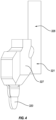
- FIG. 1 shows one example of a drilling system 100 for drilling an earth formation 101 to form a wellbore 102.
- the drilling system 100 includes a drill rig 103 used to turn a drilling tool assembly 104 which extends downward into the wellbore 102.
- the drilling tool assembly 104 may include a drill string 105, a bottomhole assembly (“BHA”) 106, and a bit 110, attached to the downhole end of drill string 105.
- BHA bottomhole assembly
- the drill string 105 may include several joints of drill pipe 108 a connected end-to-end through tool joints 109.
- the drill string 105 transmits drilling fluid through a central bore and transmits rotational power from the drill rig 103 to the BHA 106.
- the drill string 105 may further include additional components such as subs, pup joints, etc.
- the drill pipe 108 provides a hydraulic passage through which drilling fluid is pumped from the surface. The drilling fluid discharges through selected-size nozzles, jets, or other orifices in the bit 110 for the purposes of cooling the bit 110 and cutting structures thereon, and for lifting cuttings out of the wellbore 102 as it is being drilled.
- the BHA 106 may include the bit 110 or other components.
- An example BHA 106 may include additional or other components (e.g., coupled between to the drill string 105 and the bit 110).
- additional BHA components include drill collars, stabilizers, measurement-while-drilling ("MWD”) tools, logging-while-drilling (“LWD”) tools, downhole motors, underreamers, section mills, hydraulic disconnects, jars, vibration or dampening tools, other components, or combinations of the foregoing.
- the drilling system 100 may include other drilling components and accessories, such as special valves (e.g., kelly cocks, blowout preventers, and safety valves). Additional components included in the drilling system 100 may be considered a part of the drilling tool assembly 104, the drill string 105, or a part of the BHA 106 depending on their locations in the drilling system 100.
- special valves e.g., kelly cocks, blowout preventers, and safety valves.
- Additional components included in the drilling system 100 may be considered a part of the drilling tool assembly 104, the drill string 105, or a part of the BHA 106 depending on their locations in the drilling system 100.
- the bit 110 in the BHA 106 may be any type of bit suitable for degrading downhole materials.
- the bit 110 may be a drill bit suitable for drilling the earth formation 101.
- Example types of drill bits used for drilling earth formations are fixed-cutter or drag bits (see FIG. 14 ) and roller cone bits (see FIG. 2 ).
- the bit 110 may be a mill used for removing metal, composite, elastomer, other materials downhole, or combinations thereof.
- the bit 110 may be used with a whipstock to mill into casing 107 lining the wellbore 102.
- the bit 110 may also be a junk mill used to mill away tools, plugs, cement, other materials within the wellbore 102, or combinations thereof. Swarf or other cuttings formed by use of a mill may be lifted to surface, or may be allowed to fall downhole.
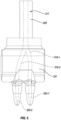
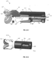
- FIG. 2 illustrates an embodiment of a bit 210 in a BHA 206 having a high-pressure ("HP") fluid conduit and a low-pressure (“LP”) fluid conduit in a bit body 211 thereof.
- the bit 210 generally includes a bit body 211, a shank 212, and a threaded connection or pin 213 for connecting the bit 210 to a drill string (e.g., drill string 105 of FIG. 1 ) that is employed to rotate the bit 210 in order to drill the borehole.
- the bit 210 is a roller cone bit having a plurality of arms 214, each supporting a roller cone 215 that is rotatable relative to the arm 214 and/or to the bit body 211.
- the bit 210 further includes a center axis 216 about which the bit 210 rotates.
- the bit 210 includes an HP fluid conduit 217 and a LP fluid conduit 218.
- the HP fluid conduit 217 may flow fluid 219 to a nozzle 220.
- the nozzle 220 directs the fluid at a high-pressure toward a formation, casing, or other material to be cut and/or weakened by the fluid.
- the LP fluid conduit 218 may flow fluid through toward one or more openings in the bit body 211 to flush debris away from the body 211, arms 214, and roller cones 215.
- the fluid 219 in the HP fluid conduit 217 and the LP fluid conduit 218 may be the same. In other embodiments, the fluid 219 in the HP fluid conduit 217 and the LP fluid conduit 218 may be different fluids.
- the LP fluid conduit 218 may flow a drilling fluid (e.g., drilling mud) therethrough to flush debris from around the bit 210.
- the HP fluid conduit 217 may experience higher rates of wear and/or erosion due at least to the higher fluid pressures compared to the LP fluid conduit 218.
- the drilling fluid may contain particulates or contaminants in mixture and/or suspension that may damage the HP fluid conduit 217.
- the HP fluid conduit 217 may flow a fluid 219 that is free of particulates, such as clean water, clean oil, or other liquid free of particulates.
- the HP fluid conduit 217 may be in fluid communication with an HP fluid pump (e.g., downhole pressure intensifier) located in the drill string (such as drill string 105 of FIG. 1 ), in the BHA (such as BHA 106 of FIG. 1 ), at the bit pin connection, at the surface, or combinations thereof.
- HP fluid pump e.g., downhole pressure intensifier
- the HP fluid conduit 217 may contain the fluid 219 at a fluid pressure in a range having upper and lower values including any of 40 kilopounds per square inch (kpsi) (276 megapascals (MPa)), 45 kpsi (310 MPa), 50 kpsi (345 MPa), 55 kpsi (379 MPa), 60 kpsi (414 MPa), 65 kpsi (448 MPa), 70 kpsi (483 MPa), 75 kpsi (517 MPa), 80 kpsi (552 MPa), or any values therebetween.
- kpsi kilopounds per square inch
- MPa megapascals
- the HP fluid conduit 217 may contain fluid 219 at a fluid pressure in a range of 40 kpsi (276 MPa) to 80 kpsi (552 MPa). In another example, the HP fluid conduit 217 may contain fluid 219 at a fluid pressure in a range of 50 kpsi (345 MPa) to 70 kpsi (483 MPa). In yet another example, the HP fluid conduit 217 may contain fluid 219 at a fluid pressure about 60 kpsi (414 MPa). In at least one embodiment, the fluid pressure of the HP fluid conduit 217 may be greater than 60 kpsi (414 MPa).
- the HP fluid conduit 217 may be cast, machined, molded, or otherwise formed in an HP body 221.
- the HP body 221 and the bit body 211 may be made of or include different materials.
- the HP body 221 may be made of or include erosion resistant materials to withstand erosion by the movement of the fluid 219 in the HP fluid conduit 217.
- the HP body 221 may be made of or include high strength alloys or materials to limit or prevent cracking of the HP body when the fluid 219 is pressurized over 40 kpsi (276 MPa), over 50 kpsi (345 MPa), over 60 kpsi (414 MPa), etc.
- the HP body 221 may be made of or include high strength steel, low carbon steel, superalloys, Maraging (martensitic-aging) steel, tungsten carbide, PDC, or other erosion-resistant materials.
- the HP body 221 may be cast, machined, or built by additive manufacturing such that the HP fluid conduit 217 is integrally formed within the HP body 221.
- the HP body 221 may be sand-cast with the HP fluid conduit 217 formed in the HP body 221.
- the HP fluid conduit 217 may be machined (i.e., bored) through a monolithic HP body 221 to produce the HP fluid conduit 217.
- additive manufacturing such as selective laser melting (“SLM”) or selective laser sintering (“SLS) may build up the HP body 221 one layer at a time while forming the HP fluid conduit 217 simultaneously.
- SLM selective laser melting
- SLS selective laser sintering
- the HP body 221 may be heat treated and/or tempered after the additive manufacturing.
- the HP body 221 may be solubilized and/or normalized to homogenize the microstructure (e.g., inducing partial and/or complete recrystallization or grain growth) to alter the mechanical properties from the as-melted or as-sintered material.
- the HP body 221 may be connected to the bit body 211 by a variety of connection methods or combinations thereof.
- the HP body 221 may be bonded to the bit body 211, for example, by welding, brazing, or other bonding of the materials of the HP body 221 and the bit body 211.
- the HP body 221 and the bit body 211 may be joined by one or more mechanically interlocking features, such as a tongue-and-groove connection, a dovetail connection, a friction fit, a pinned connection, or combinations thereof.
- non-weldable materials such as tungsten carbide may be joined by a sliding dovetail connection between the HP body 221 and the bit body 211, and the HP body 221 and bit body 211 may be fixed relative to one another by subsequent securing of the HP body 221 and the bit body 211 in the direction of the sliding dovetail (such as by welding a cap over the connection).
- the HP body 221 and the bit body 211 may be joined with the use of one or more adhesives.
- the HP body 221 and the bit body 211 may be joined by a combination of the foregoing, such as through welding of mechanically interlocking faces of the HP body 221 and the bit body 211.
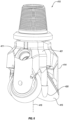
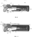
- FIG. 3 illustrates a side view of another embodiment of a bit 310.
- the bit 310 depicted in FIG. 3 has two roller cones 315 supported by arms 314 on opposing sides of a bit body 311.
- the bit body 311 is welded to an HP body 321.
- the bit body 311 and/or the HP body 321 include a gage surface 324.
- the gage surface 324 may be the radially outermost surface of the bit body 311 and/or the HP body 321.
- the gage surface 324 may include one or more inserts 325 embedded and/or fixed thereto.
- one or more inserts 325 may be located on a gage surface 324 of the bit body 311.
- one or more inserts 325 may be located on the gage surface 324 of the HP body 321.
- the bit 310 may be rotatable, as described in relation to FIG. 1 and FIG. 2 .
- At least one nozzle 320 may be positioned rotationally between the roller cones 315 of the bit 310.
- the nozzle 320 may direct a fluid jet 322 from the nozzle 320 toward a location in the rotational path of the roller cones 315 and between the roller cones 315.
- the fluid jet 322 may weaken the formation or other material adjacent the bit 310 and the teeth 323 of the roller cones 315 may remove material.
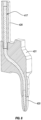
- FIG. 4 illustrates the HP body 321 of the bit 310 shown in FIG. 3 .
- the HP body 321 may have a shaft 326 that extends longitudinally (i.e., in the direction of the center axis of the bit).
- the shaft 326 is integrally formed in the HP body 321.
- the HP body 321 has a lateral surface 327 that may contact and/or abut the bit body.
- at least a portion of the lateral surface 327 may be welded, brazed, or otherwise bonded to a portion of the bit body.
- the lateral surface 327 may have one or more interlocking features that mechanically interlock with one or more complimentary interlocking features on the bit body.
- a nozzle 320 is integrally formed with the HP body 321.
- the nozzle 320 be made of or include a different material from the HP body 321 and may be connected to the HP body 321 after manufacturing of the HP body 321.
- the nozzle 320 may include or be made of an ultrahard material.
- ultrahard is understood to refer to those materials known in the art to have a grain hardness of about 1,500 HV (Vickers hardness in kg/mm2) or greater.
- ultrahard materials can include but are not limited to diamond, sapphire, moissantite, polycrystalline diamond (PCD), leached metal catalyst PCD, non-metal catalyst PCD, hexagonal diamond (Lonsdaleite), cubic boron nitride (cBN), polycrystalline cBN (PcBN), binderless PCD or nanopolycrystalline diamond (NPD), Q-carbon, binderless PcBN, diamond-like carbon, boron suboxide, aluminum manganese boride, metal borides, boron carbon nitride, and other materials in the boron-nitrogen-carbon-oxygen system which have shown hardness values above 1,500 HV, as well as combinations of the above materials.
- PCD polycrystalline diamond
- leached metal catalyst PCD non-metal catalyst PCD
- hexagonal diamond Lionsdaleite
- cBN cubic boron nitride
- PcBN polycrystalline cBN
- NPD nanopolycrystalline diamond
- Q-carbon Q-carbon
- the nozzle 320 may be a monolithic PCD.
- the nozzle 320 may consist of a PCD compact without an attached substrate.
- the nozzle 320 may have an ultrahard coating on an inner diameter of a substrate.
- the ultrahard material may have a hardness values above 3,000 HV.
- the ultrahard material may have a hardness value above 4,000 HV.
- the ultrahard material may have a hardness value greater than 80 HRa (Rockwell hardness A).
- FIG. 5 is a cross-sectional view of the HP body 321 showing the HP fluid conduit 317 in the shaft 326 to the plurality of nozzles 320-1, 320-2.
- the HP body 321 has an HP fluid conduit 317 that divides to provide a first fluid 319-1 to the first nozzle 320-1 and a second fluid 319-2 to the second nozzle 320-2.
- the HP body 321 may have a first HP fluid conduit and a second HP fluid conduit that are discrete from one another.
- a first HP fluid conduit and a second HP fluid conduit may independently provide a first fluid to a first nozzle and a second fluid to a second nozzle without the first fluid and the second fluid mixing.
- a plurality of discrete HP fluid conduits may allow different fluids and/or different pressures to be utilized in different locations on the bit or for different applications.
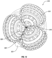
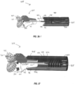
- FIG. 6 illustrates another embodiment of a bit 410 including an HP body 421.
- the depicted bit 410 includes more than two roller cones 415 that are located at equal angular intervals relative to one another about the center axis 416 of the bit 410.
- the depicted bit 410 has three arms 414 angularly spaced at 120° intervals. In other embodiments four arms may be spaced at 90° intervals. In yet other embodiments, five arms may be spaced at 72° intervals. In further embodiments, two or more arms 414 may be spaced at unequal angular intervals.
- Embodiments of bits with more arms 414 and/or roller cones 415 may have less angular space between the arms 414 and/or roller cones 415, limiting the number of nozzles 420 positionable between the arms 414 and/or roller cones 415.
- the embodiment of a bit 310 described in relation to FIG. 3 through FIG. 5 has two roller cones 315 and the HP body 321 has two nozzles 320 in the angular space between the two roller cones 315
- the embodiment of a bit 410 in FIG. 6 through FIG. 10 has three arms 414 and roller cones 415 and the HP body 421 has one nozzle 420 in the angular space between roller cones 415.
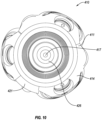
- FIG. 7 illustrates the HP body 421 with a single nozzle 420 independent of the remainder of the bit.
- the HP body 42 similarly to the HP body 321 described in relation to FIG. 4 , has a shaft 426 that extends longitudinally (i.e., in the direction of the center axis 416 of the bit).
- the shaft 426 is integrally formed in the HP body 421.
- the HP body 421 has a lateral surface 427 that may contact and/or abut the bit body. In some embodiments, at least a portion of the lateral surface 427 may be welded, brazed, or otherwise bonded to a portion of the bit body. In other embodiments, the lateral surface 427 may have one or more interlocking features that mechanically interlock with one or more complimentary interlocking features on the bit body.
- a cross-section of the HP body 421 of FIG. 7 shows the HP fluid conduit 417 located at least partially in the shaft 426 and providing fluid communication through the longitudinal length of the HP body 421 to the nozzle 420.
- the shaft 426 may be a separate component from the HP body 421.
- the shaft 426 and HP body 421 may be bonded to one another, for example, by welding, brazing, or other bonding of the materials of the shaft 426 and HP body 421.
- the shaft 426 and HP body 421 may be joined by one or more mechanically interlocking features, such as a tongue-and-groove connection, a dovetail connection, a friction fit, a pinned connection, or combinations thereof.
- mechanically interlocking features such as a tongue-and-groove connection, a dovetail connection, a friction fit, a pinned connection, or combinations thereof.
- non-weldable materials such as tungsten carbide may be joined by a sliding dovetail connection between the shaft 426 and HP body 421, and the shaft 426 and HP body 421 may be fixed relative to one another by subsequent securing of the shaft 426 and HP body 421 in the direction of the sliding dovetail (such as by welding a cap over the connection).
- the shaft 426 and HP body 421 may be joined with the use of one or more adhesives.
- the shaft 426 and HP body 421 may be joined by a combination of the foregoing, such as through welding of mechanically interlocking faces of the shaft 426 and HP body 421.
- the shaft may be integrally formed with the HP body.
- a bit 410 may include a plurality of HP bodies 421 and associated nozzles 420 connected to the bit body.
- a bit 410 may have a second nozzle between the second roller cone 415-2 and the third roller cone 415-3.
- the angular spacing 445 between nozzles 420 may be at least partially dependent upon the angular spacing between the roller cones 415.
- the angular spacing 445 between a position of the nozzle 420 (between the first roller cone 415-1 and the second roller cone 415-2) and a position between the second roller cone 415-2 and the third roller cone 415-3 may be in a range having upper and lower values including any of 60°, 70°, 80°, 90°, 100°, 110°, 120°, 130°, 140°, 150°, 160°, 170°, 180°, or any values therebetween.
- the angular spacing 445 between the nozzle 420 (between the first roller cone 415-1 and the second roller cone 415-2) and a position between the second roller cone 415-2 and the third roller cone 415-3 may be in a range of 60° to 180°.
- the angular spacing 445 between the nozzle 420 (between the first roller cone 415-1 and the second roller cone 415-2) and a position between the second roller cone 415-2 and the third roller cone 415-3 may be in a range of 80° to 130°. In yet another example, the angular spacing 445 between the nozzle 420 (between the first roller cone 415-1 and the second roller cone 415-2) and a position between the second roller cone 415-2 and the third roller cone 415-3 may be in a range of 90° to 120°.
- the nozzle 420 is located a radial position 428 from the center axis 416.
- the radial position 428 of the nozzle 420 may be in a range having upper and lower values including any of 50%, 55%, 60%, 65%, 70%, 75%, 80%, 85%, 90%, 95%, 100%, or any values therebetween of the total radius of the bit 410 (i.e., the distance from the center axis 416 to a gage surface).
- the nozzle 420 may have a radial position 428 that is in a range of 50% to 100% of the total radius of the bit 410.
- the nozzle 420 may have a radial position 428 that is in a range of 60% to 95% of the total radius of the bit 410. In yet another example, the nozzle 420 may have a radial position 428 that is in a range of 70% to 90% of the total radius of the bit 410.
- FIG. 10 is a top view of the embodiment of a bit 410 in FIG. 6 .
- the HP fluid conduit 417 provides fluid communication to a fluid pump or fluid source uphole in the drill string through the shaft 426 of the HP body 421 and to the nozzle 420.
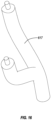
- FIG. 11 is an embodiment of a bit 510, according to the present disclosure, in which the nozzle 520 and HP body 521 are located externally to the bit body 511.
- the bit 510 has an HP body 521 that is connected to the bit body 511 externally.
- the HP body 521 is located angularly between the arms 514 and/or roller cones 515 of the bit 510.
- the external HP body 521 may be bonded to the bit body 511, for example, by welding, brazing, or other bonding of the materials of the external HP body 521 and the bit body 511.
- the external HP body 521 and the bit body 511 may be joined by one or more mechanically interlocking features, such as a tongue-and-groove connection, a dovetail connection, a friction fit, a pinned connection, or combinations thereof.
- the external HP body 521 and the bit body 511 may be joined with the use of one or more adhesives.
- the external HP body 521 and the bit body 511 may be joined by a combination of the foregoing, such as through welding of mechanically interlocking faces of the external HP body 521 and the bit body 511.
- the external HP body 521 may be positioned at least partially radially within the bit body 511.
- the shaft 526 may extend in a longitudinal direction and provide fluid communication to the nozzle 520 (shown in FIG. 13).
- FIG. 13 is a bottom view of the bit 510 illustrating the radial displacement of the nozzle 520 radially inward toward the center axis 516.
- the external HP body 521 may curve or otherwise angle radially inward to support the nozzle 520 closer to the center axis 516 and/or the roller cones 515.
- a radial position 528 of the nozzle 520 may be in a range having upper and lower values including any of 50%, 55%, 60%, 65%, 70%, 75%, 80%, 85%, 90%, 95%, 100%, or any values therebetween of the total radius of the bit 510 (i.e., the distance from the center axis 516 to a gage surface).
- the nozzle 520 may have a radial position 528 that is in a range of 50% to 100% of the total radius of the bit 510.
- the nozzle 520 may have a radial position 528 that is in a range of 60% to 95% of the total radius of the bit 510.
- the nozzle 520 may have a radial position 528 that is in a range of 70% to 90% of the total radius of the bit 510.
- an inner diameter ("ID") of a nozzle 520 may be in a range having upper and lower values including any of 0.010 in. (0. 254 mm), 0.015 in. (0.381 mm), 0.020 in. (0.508 mm), 0.025 in. (0.635 mm), 0.030 in. (0.762 mm), 0.035 in. (0.889 mm), or any values therebetween.
- an ID of a nozzle 520 may be between 0.010 in. (0.254 mm) and 0.035 in. (0.889 mm).
- the ID of a nozzle 520 may be between 0.015 in. (0.381 mm) and 0.030 in. (0.762 mm).
- the plurality of nozzles 520 may be fixed relative to the HP body 521. In other embodiments, the plurality of nozzles 520 may be movable relative to the HP body 521. For example, the plurality of nozzles 520 may be rotatable relative to the HP body 521. In other words, the four nozzles 520 at the end of the HP body 521 may rotate to distribute the HP fluid jet ejected from each nozzle over a larger area during use of the bit 510. The rotation of the nozzles 520, combined with the rotation of the bit 510 during use, may create a wave form, spiral function, or other repeating path pattern of the fluid jet.
- an HP fluid conduit may be applicable in other applications, such as an embodiment of a PDC bit shown in FIG. 14 .
- the embodiment of a PDC bit 610 has a plurality of primary blades 629 and a plurality of secondary blades 630 extending radially outward from a center axis 616 of the bit 610.
- a PDC bit may have only primary blades.
- Each of the blades 629, 630 has a cutting surface 631 oriented in the rotational direction of the PDC bit indicated by the arrow 632.
- the cutting surface 631 and/or other surfaces of the blades 629, 630 may have one or more cutting elements 633, such as PDC cutters, positioned thereon.
- One or more LP fluid conduits 618 may be positioned in the bit 610 to flush away debris cut by the cutting elements 633.
- the PDC bit 610 may use one or more HP fluid conduits to deliver fluid to nozzles.
- the PDC bit 610 has a first nozzle 620-1 on a primary blade and a second nozzle 620-2 on another primary blade 629.
- a nozzle may be located on a secondary blade 630.
- a nozzle may be located on the bit 610 between the primary blades 629 and secondary blades 630 in the body of the bit where the LP fluid conduits 618 are located.
- the first nozzle 620-1 and second nozzle 620-2 may be located on different blades. In some embodiments, the first nozzle 620-1 and second nozzle 620-2 may be positioned on the bit 610 relative to the center axis 616 at an angular spacing 645 (similar to the angular spacing between roller cones in a roller cone bit embodiment).
- the angular spacing 645 may be in a range having upper and lower values including any of 0° (i.e., angularly aligned along a radial line from the center axis 616), 10°, 20°, 30°, 40°, 50°, 60°, 70°, 80°, 90°, 100°, 110°, 120°, 130°, 140°, 150°, 160°, 170°, 180° (i.e., opposing one another on opposite sides of the center axis 616), or any values therebetween.
- the angular spacing 645 may be in a range of 0° to 180°.
- the angular spacing 645 may be in a range of 20° to 150°.
- the angular spacing 645 may be in a range of 40° to 120°.
- the first nozzle 620-1 and second nozzle 620-2 may be located at the same radial distance or different radial distances. In some embodiments, the first nozzle 620-1 may be located at a first radial distance 628-1 and the second nozzle 620-2 may be located at a second radial distance 628-2 that is less than the first radial distance 628-1. In other embodiments, the first nozzle 620-1 may be located at a first radial distance 628-1 and the second nozzle 620-2 may be located at a second radial distance 628-2 that is greater than the first radial distance 628-1.
- the first nozzle 620-1 may be located at a first radial distance 628-1 and the second nozzle 620-2 may be located at a second radial distance 628-2 that is the same as the first radial distance 628-1.
- FIG. 15 depicts the relative angles at which a fluid jet may be oriented relative to the bit 610.
- the first nozzle 620-1 is shown with a rake angle 634 relative to the rotational direction of the bit 610 shown as arrow 632.
- the rake angle 634 may be a positive rake angle (in the direction of the rotation), a negative rake angle (against the direction of rotation), or a neutral rake angle (parallel to the center axis 616).
- the rake angle 634 may be in a range having upper and lower values including any of -30°, -20°, -15°, -10°, -5°, 0°, 5°, 10°, 15°, 20°, 30°, or any values therebetween.
- the rake angle 634 may be in a range of -30° to 30°.
- the rake angle 634 may be in a range of -20° to 20°.
- the rake angle 634 may be in a range of -15° to 15°.
- the second nozzle 620-2 is shown with a siderake angle 635 relative to the radial distance 628.
- the siderake angle 635 may be a positive siderake angle (away from the center axis 616), a negative siderake angle (toward the center axis 616), or a neutral siderake angle (parallel to the center axis 616).
- the siderake angle 635 may be in a range having upper and lower values including any of -30°, -20°, -15°, -10°, -5°, 0°, 5°, 10°, 15°, 20°, 30°, or any values therebetween.
- the siderake angle 635 may be in a range of -30° to 30°.
- the siderake angle 635 may be in a range of -20° to 20°.
- the siderake angle 635 may be in a range of -15° to 15°.
- a PDC bit may have integral HP fluid conduits that are cast into the bit body.
- a PDC bit may have an HP fluid conduit 617, such as that shown in FIG. 16 , around which the PDC bit may be cast or sintered.
- HP fluid conduit 617 is formed from a material capable of withstanding fluid pressures greater than 40 kilopounds per square inch (kpsi) (276 megapascals (MPa)).
- a hybrid bit 710 may include at least one arm 714 and/or roller cone 715, as well as at least one primary blade 729 with a cutting surface 731.
- the hybrid bit 710 has one or more HP bodies 721 connected to the hybrid bit 710.
- the hybrid bit 710 may have at least one HP body 721 positioned between a roller cone 715 and a primary blade 729, in front of the cutting surface 731.
- the hybrid bit 710 may have at least one HP body 721 positioned between a roller cone 715 and a primary blade 729, behind the cutting surface 731.
- FIG. 18 and FIG. 19 schematically illustrate a transverse cross-section of an embodiment of an interaction of a fluid jet from a nozzle with an earth formation during use of a bit according to the present disclosure.
- FIG. 18 shows a first nozzle 820-1 directing a fluid jet 822 toward the formation 801 to create a first cut 836-1 in the formation 801.
- the fluid jet 822 is shown at a neutral radial incident angle 847 (i.e., perpendicular to a surface of the formation 801 in a radial direction).
- a radial incident angle 847 relative to the surface of the formation may be in a range having upper and lower values including any of -30°, -20°, -15°, -10°, -5°, 0°, 5°, 10°, 15°, 20°, 30°, or any values therebetween.
- the radial incident angle 847 may be in a range of -30° to 30°.
- the radial incident angle 847 may be in a range of -20° to 20°.
- the radial incident angle 847 may be in a range of -15° to 15°.
- the radial incident angle 847 may affect the shape and depth of the first cut 836-1.
- the radial incident angle 847 may be at least partially based on the type of formation 801 being cut.
- the radial incident angle 847 may be at least partially dependent upon the siderake angle of a nozzle (such as siderake angle 635 described in relation to FIG. 15 ).
- the jet length 846 is a distance from the first nozzle 820-1 to the formation 801.
- the jet length 846 may be in a range having upper and lower values including any of 0.05 in. (1.27 mm), 0.10 in. (2.54 mm), 0.15 in. (3.81 mm), 0.20 in. (5.08 mm), 0.25 in. (6.35 mm), 0.30 in. (7.62 mm), 0.35 in. (8.89 mm), 0.40 in. (10.2 mm), 0.45 in. (11.4 mm), 0.50 in. (12.7 mm), 0.55 in. (14.0 mm), 0.60 in. (15.2 mm), 0.65 in. (16.5 mm), 0.70 in. (17.8 mm), 0.75 in.
- a jet length 846 may be between 0.05 in. (1.27 mm) and 1.0 in. (25.4 mm). In other examples, a jet length 846 may be between 0.10 in. and 0.95 in.. In yet other examples, a jet length 846 may be between 0.15 in. and 0.90 in..
- the jet length 846, fluid pressure, rotational speed, downhole hydrostatic pressure, rock strength, rake angle (such as rake angle 634 described in relation to FIG. 15 ), and radial incident angle 847 of the fluid jet 822 produced by the first nozzle 820-1 may affect the shape and depth of the first cut 836-1.
- the first cut 836-1 may weaken a surface of the formation 801 allowing a bit to more readily remove material from the formation 801.
- FIG. 19 illustrates a second nozzle 820-2 positioned at a different radial distance from the first nozzle of FIG. 18 (similarly to the first nozzle 620-1 and second nozzle 620-2 described in relation to FIG. 14 ).
- the second nozzle 620-2 creates a second cut 836-2.
- An unsupported region 837 is formed between the two cuts disconnected from the formation 801 on at least two sides of the unsupported region 837.
- the unsupported region 837of the formation 801 is less stable than a supported region 838 which is still disconnected to the formation 801 on only one side of the supported region.
- Creation of unsupported regions 837 of formation 801 during rotation of a roller cone bit, PDC bit or drag bit, hybrid bit, or other forms of cutting bits may reduce torque on the drilling system, reduce wear on the bit, increase the rate of penetration, reduce energy expenditure, reduce stick-slip behavior, provide other benefits, or combinations thereof.
- FIG. 20 A flowchart of an embodiment of a method 939 of using a bit according to the present disclosure is shown in FIG. 20 .
- the method 939 includes flowing 940 a fluid through an HP fluid conduit at a fluid pressure greater than 40 kpsi (276 MPa) and directing 941 the fluid at a formation.
- the method 939 further includes weakening 942 the formation with the HP fluid jet and then removing 943 at least a portion of the weakened region of the formation before flushing 944 the cuttings of the weakened region away.
- removing 943 weakened region may include using a roller cone and/or a blade having cutting elements on the blade.
- flushing 944 material may be performed with a LP fluid delivered through a LP fluid conduit.
- the flushing 944 may include using the fluid from the HP fluid conduit.
- FIG. 21 schematically illustrates a high-pressure drill bit system 908 of a BHA 906 in accordance with some aspects of the present disclosure.
- the high-pressure drill bit 910 may include roller cones 915 and one or more HP nozzles 920.
- a bit pin 913 facilitates coupling the drill bit 910 to a connection 916 (e.g., box connection) of a component 918 of the BHA 906.
- the high-pressure drill bit 910 may include one or more non-HP nozzles 922 (e.g., LP nozzles or LP openings).
- the one or more HP nozzles 920 may be coupled to a first fluid conduit 917 (e.g., rigid connector), while the non-HP nozzles 922 are connected to a second fluid conduit 930.
- the HP nozzle 920 may be coupled to the rigid connector 917 and an HP pipe 924 via an HP connection interface 926.
- the one or more HP nozzles 920 may direct a HP fluid 921 toward a formation
- the one or more non-HP nozzles 922 may direct a LP fluid 923 toward the formation, the roller cones 915, or portions of the drill bit 910.
- the HP connection interface 926 may be at least partially within a passage 932 that conveys the LP fluid 923 to the drill bit 910.
- Fluid 921 in the HP pipe 924 may flow from a downhole pressure intensifier 928 (e.g., pump, motor) that takes fluid flow in the downhole BHA 906 and increases pressure.
- the downhole pressure intensifier 928 (DPI) is coupled directly to the drill bit 910.
- the DPI 928 may be indirectly coupled to the drill bit 910 via intermediate components 918, such as components 918 of the BHA 906.
- the DPI 928 is disposed on a surface, and the DPI 928 supplies the HP fluid 921 to the HP pipe 924, which directs the HP fluid 921 to the fluid conduit 917 of the drill bit 910.
- the fluid 921 having the increased pressure from the DPI 928 will flow into the HP pipe 924.
- a second fluid e.g., LP fluid 923 in the downhole system 908 may flow through the DPI 928 without pressure intensification or with reduced pressure intensification.
- the LP fluid 923 may flow around the DPI 928.
- the high-pressure fluid 921 may go through the drill bit fluid conduit 917 and into the HP nozzles 920, while the low-pressure fluid 923 may go through the drill bit 910 and into one or more lower pressure nozzles 922 via the passage 932.
- the low pressure fluid 923 may be directed from the passage 932 to a plenum within the drill bit 910 for distribution to the one or more low pressure nozzles 922.
- the high-pressure nozzles 920, high-pressure pipe 924, and fluid conduit 917 receive flow-pressure or flow rates consistent with the high-pressure flows discussed herein, while the bit plenum and low-pressure nozzles 922 receive fluid pressure generally consistent with a standard bit.
- the HP fluid 921 may have a pressure greater than 14.5 ksi, 20 ksi, 25 ksi, 30 ksi, 40 ksi, 50 ksi, 60 ksi, or more.
- the LP fluid 923 may have a pressure less than the HP fluid 921 that is suitable for removing cuttings from the wellbore, such as less than 14.5 ksi, 10 ksi, 5 ksi, 1 ksi, or less.
- the high-pressure and low-pressure nozzles may extend from the drill bit 910 at about a same axial position; however, in other embodiments, the high-pressure nozzles 920 may extend farther downhole than the low-pressure nozzles 922, or vice versa. According to at least some embodiments, the high-pressure nozzles 920 may provide flow 921 with reduced cuttings removable capabilities as compared to the low-pressure nozzles 922.
- the system 908 of FIG. 21 may be varied in any number of manners, including the configurations of the connection between the drill bit 910 and high-pressure pipe 924 configured to provide the HP fluid 921 to the HP nozzles 920.
- FIGS. 22-28 illustrate examples of the connections between the drill bit 910 and the DPI 928 of the DPI component 948. Although some of the examples illustrate the fluid conduit 917 of the drill bit 910 coupled directly to the high-pressure pipe 924 and the DPI 928, it is appreciated that one or more intermediate components 918 of the BHA 906 may be coupled between the fluid conduit 917 and the DPI 928. That is, the HP connection interface 926 described herein may be within the DPI 928, a steerable system component, a motor, a collar, a drill pipe, a sensor, a stabilizer, a reamer, and so forth.
- FIG. 22 illustrates an example of connecting a DPI component 948 to a drill bit 910, while using rigid connections at the HP connection interface 926, while also providing axial displacement while torqueing an API or other threaded connection at the drill bit 910 and DPI component 948.
- the threaded connection is between the bit pin 913 and the box connection 916 of the DPI component 948.
- the fluid conduit 917 or tube is coupled to the drill bit 910 and the HP pipe 924 or tube is connected within the DPI 928 of the DPI component 948.
- both the fluid conduit 917 and the HP pipe 924 are rigid elements rather than flexible elements.
- a static seal 950 may then provide a connection (e.g., with tapered nose and cone configuration illustrated in FIG. 29 ) between the rigid connectors (e.g., fluid conduit 917 and HP pipe 924). That is, an inlet portion 952 of the fluid conduit 917 may be received by an outlet portion 954 of the HP pipe 924. In some embodiments, the inlet portion 952 of the fluid conduit 917 may receive the outlet portion 954 of the HP pipe 924.
- the static seal 950, the fluid conduit 917, and the HP pipe 924 define a high-pressure connection interface 926 that is at least partially within, and fluidly isolated from, the low pressure fluid 923 within the passage 932.
- the high-pressure connection interface 926 is also fluidly isolated from a low pressure plenum 934 within the drill bit 910.
- the HP connection interface 926 may have a volume 956 sized to allow axial movement therein of one or both of the inlet portion 952 and the outlet portion 954 while the static seal 950 maintains isolation of the HP fluid 921 from the LP fluid 923.
- the static seal 950 may be a compression ring, such as an elastomeric compression ring or a metallic (e.g., copper) compression ring.
- the static seal 950 may facilitate relative axial and circumferential movement of the inlet portion 952 and the outlet portion 954 during connection of the drill bit 910 with the component 948. That is, the high-pressure connection interface 926 with the static seal illustrated in FIG. 22 may be formed simultaneously with the connection of the drill bit 910 with the DPI component 948.
- the static seal 950 of the high-pressure connection interface 926 can be used to create a seal whether the static seal 950 is used between two rigid tubes, two flexible tubes, or a flexible tube and a rigid tube.
- FIGS. 23-1 and 23-2 illustrate a similar design for a drill bit 910 and DPI component 948.
- the DPI component 948 includes an access window 970 that may be selectively opened or closed. When opened at the surface, personnel may access the static seal 950 of the HP connection interface 926.
- bolts 972, seals, or other components may be used to seal the window 970 closed and to open/close the window 970.
- the window 970 is closed, the low-pressure fluid 923 may flow through the passage 932 of the DPI component 948 to the plenum 934 of the drill bit 910.
- the cover of the window 970 may be shaped to ensure good flow of the mud and to reduce erosion within the passage 932.
- axial displacement within the static seal 950 via a volume 956; however, in the same or other embodiments axial displacement may be provided in other manners.
- an axial tubing displacement of the fluid conduit 917 and/or the HP pipe 924 may be provided (e.g., in or near the downhole pressure intensifier) to connect and compensate for length when the bit 910 is connected to the drill collar or DPI component 948.
- an intermediate HP conduit may be inserted through the window 970 of the component to couple the fluid conduit 917 with the HP pipe 924 after the drill bit 910 is connected to the component.
- a threaded portion 974 of the HP pipe 924 may extend through an upstream end of the component 948 to facilitate a seal via a fastener 976 with a conical shape, as discussed below with FIG. 29 .
- FIGS. 24-1 and 24-2 illustrate another example connection for the high-pressure flow between a drill bit 910 and a DPI component 948.
- the bit 910 may include a static tube (e.g., fluid conduit 917), and a flexible tube 980 or hose may be coupled to the inlet portion 952 of the fluid conduit 917 to fluidly couple the HP nozzle 920 with the DPI 928.
- an access window 970 may also be included in the outer wall of the DPI component 948, or in a drill collar component between the bit 910 and the DPI 928.
- the flexible tube 980 may facilitate axial and/or radial movement along the high-pressure fluid flow elements between the drill bit 910 and the DPI 928.
- the access window 970 may facilitate the connection of the fluid conduit 917 with the flexible tube 980 after the connection (e.g., API connection) between the drill bit 910 and the DPI component 948.
- the flexible tube 980 may be directly coupled to the drill bit 910, and the HP pipe 924 may be the rigid component of the HP connection interface 926.
- FIG. 25 shows another example connection for the high-pressure flow between a drill bit 910 and a DPI component 948.
- an optional access window 970 may be included, as is a flexible tube 980, hose or other flow component coupled to the DPI 928.
- the DPI component 948 may also include a swivel connection 982 to the flexible tube 980 that allows rotation of the flexible tube 980 when the drill bit 910 and DPI component 948 are made up.
- the access window 970 allows assembly of the connection 926 after make-up of the drill bit 910 and DPI component 948.
- the swivel connection 982 may be disposed on either end of the flexible tube 980 or the fluid conduit 917.
- the HP connection interface 926 includes a swivel connection 982
- FIGS. 26-1 and 26-2 illustrate another example connection for a high-pressure flow between a drill bit 910 and a DPI component 948.
- the flexible tube 980 of the DPI component 948 may be coupled to the fluid conduit 917 (e.g., rigid conduit) of the drill bit 910 before make-up with the DPI component 948.
- the flexible tube 980 may have enough length to compensate for make-up, as the flexible tube 980 or hose may coil within the passage 932 during torqueing, as illustrated in FIG. 26-2 .
- the flexible tube 980 may be initially coupled to the fluid conduit 917 of the drill bit 910 outside of the passage 932 of the DPI component 948, as illustrated in FIG. 26-1 .
- the extended length of the flexible tube 980 may extend beyond a downhole end 984 of the DPI component 948.
- the window 970 discussed with FIG. 23 may facilitate forming the HP connection interface 926 after connecting the drill bit 910 to the DPI component 948
- the flexible tube 980 and the length thereof described with FIG. 26 may facilitate forming the HP connection interface 926 prior to connecting the drill bit 910 to the DPI component 948.
- FIGS. 26-1 and 26-2 may also be modified to include the swivel connection 982 or other rotatable connection between the flexible tube 980 and the DPI 928, as shown in the embodiment of FIG. 27 .
- the swivel connection 982 or other rotatable connector is also or instead used between the fluid conduit 917 (e.g., rigid connector) and the drill bit 910.
- the fluid conduit 917 of the drill bit 910 is flexible.
- both the fluid conduit 917 of the drill bit 910 and the HP pipe 924 of the DPI component 948 may be rigid, both may be flexible, or either one may be flexible while the other is rigid.
- FIG. 28 illustrates another embodiment of the high pressure drill bit system 908 combining other features described in more detail herein.
- the swivel connection 982 is included between the flexible tube 980 and the DPI 928, as shown with enlarged view "a" of FIG. 28 .
- the flexible tube 980 (as shown with enlarged view “b” of FIG. 28 ) may have sufficient length to facilitate coupling with the fluid conduit 917 outside of the passage 932 and to be coiled within the passage 932 upon connection of the drill bit 910 with the DPI component 948 (as shown with view "c" of FIG. 28 ).
- FIG. 28 illustrates another embodiment of the high pressure drill bit system 908 combining other features described in more detail herein.
- the swivel connection 982 is included between the flexible tube 980 and the DPI 928, as shown with enlarged view "a" of FIG. 28 .
- the flexible tube 980 (as shown with enlarged view "b” of FIG. 28 ) may have sufficient length to facilitate coup
- the threaded portion 974 of the HP pipe 924 may be connected to the DPI 928 with the fastener 976. Additionally, axial regulation is included in the DPI 928 and/or in the high-pressure connection interface 926 to allow the flexible tube 980 to be moved axially relative to the connection to the DPI 928.
- Embodiments of the present disclosure have shown preliminary results that are promising for the field. For instance, an example embodiment of a drill bit with one high-pressure nozzle was shown to have a 70% rate of penetration increase relative to a comparable standard roller cone bit when drilling in granite. An example embodiment with two high-pressure nozzles was shown to have a 42% rate of penetration increase over the baseline bit.
- FIG. 29 illustrates some examples of HP connections that may be used in accordance with embodiments of the present disclosure.
- the illustrated connections may be similar to those used in other high-pressure applications (e.g., water jetting), and may be rated for pressures of 1,000 to 10,000 bar or 14,500 to 145,000 psi.
- embodiments may include connecting an HP connector/pipe to a rigid bit connection and sliding a flexible connector through the box connection of the downhole pressure intensifier.
- the box connection may be coupled to the bit pin.
- swivels, axial compensation, access windows, or other techniques may be used to facilitate high-pressure connections.
- bits and fluid conduits may be used in applications other than the drilling of a wellbore.
- bits and fluid conduits according to the present disclosure may be used outside a wellbore or other downhole environment used for the exploration or production of natural resources.
- bits and fluid conduits of the present disclosure may be used in a borehole used for placement of utility lines.
- bits and fluid conduits of the present disclosure may be used in wireline applications and/or maintenance applications. Accordingly, the terms "wellbore,” “borehole,” and the like should not be interpreted to limit tools, systems, assemblies, or methods of the present disclosure to any particular industry, field, or environment.
- any element described in relation to an embodiment or a figure herein may be combinable with any element of any other embodiment or figure described herein.
- Numbers, percentages, ratios, or other values stated herein are intended to include that value, and also other values that are "about” or “approximately” the stated value, as would be appreciated by one of ordinary skill in the art encompassed by embodiments of the present disclosure.
- a stated value should therefore be interpreted broadly enough to encompass values that are at least close enough to the stated value to perform a desired function or achieve a desired result.
- the stated values include at least the variation to be expected in a suitable manufacturing or production process, and may include values that are within 5%, within 1%, within 0.1%, or within 0.01% of a stated value.
- any references to “up” and “down” or “above” or “below” are merely descriptive of the relative position or movement of the related elements.
Description
- Downhole systems may be used to drill, service, or perform other operations on a wellbore in a surface location or a seabed for a variety of exploratory or extraction purposes. For example, a wellbore may be drilled to access valuable subterranean resources, such as liquid and gaseous hydrocarbons and solid minerals stored in subterranean formations, and to extract the resources from the formations.
- Drilling systems are conventionally used to remove material from earth formations and other material, such as concrete, through primarily mechanical means. Drag bits, roller cone bits, reciprocating bits, and other mechanical bits fracture, pulverize, break, or otherwise remove material through the direct application of force. Different formations require different amounts of force to remove material. Increasing the amount of mechanical force applied to the formation includes increasing the torque and weight on bit on the drilling system, both of which introduce additional challenges to the drilling system.
- Some mechanical bits include fluid conduits therethrough to direct drilling fluid to the cutting elements in order to flush cuttings and other debris from the cutting surfaces of the bit. Efficient removal of waste from the cutting area of the bit can reduce the torque and WOB used to remove material from the formation. Increasing the fluid pressure in a conventional bit erodes the bit and decreases the reliability and operational lifetime of the bit. A bit with one or more features that reduce the mechanical force to remove material from the formation without adversely affecting the reliability and lifetime of the bit is, therefore, desirable.
-
US 2013/199849 A1 describes a jet drilling method using up and down vibrations of a drill string or weight on bit variation during the drilling process, so that an upper joint connected to the drill string drives a housing and a supercharging cylinder block to move up and down relative to a supercharging piston, while the supercharging piston, a high pressure line, and a drive shaft disposed outside the high pressure line make a reciprocally retractable movement relative to the housing. As a result, some working fluid entering the supercharging cylinder block is intermittently supercharged and discharged from a high pressure fluid passage disposed in the supercharging piston and the high pressure line.US 6289998 B1 describes a drilling system utilizing the drilling fluid in a borehole to drive an apparatus to generate a high-pressure jet of fluid to facilitate the drilling operation. A pressure intensifier disposed between a drilling motor and the drill bit generates high pressure fluid jet. The drilling motor rotates the pressure intensifier, with fluid entering a high pressure chamber in the pressure intensifier at selected location during each rotation. A piston in the pressure intensifier discharges the fluid from the high pressure chamber to the drill bit bottom at a high pressure.US 2014/116783 A1 describes a method of sampling while drilling comprising positioning a sample chamber through an opening in an outer wall of a drill collar, wherein the outer wall extends between first and second ends of the drill collar and conducting a drilling fluid through a passage in the drill collar.US 5787998 A describes a jet assisted drill system which uses a high pressure intensifier, positioned in a down hole drill assembly. Drill fluid from a drill stem is directed into the drill assembly, and in one mode this drill fluid is passed through the pressure intensifier to cause a piston assembly of the intensifier to reciprocate, with high pressure pistons of the piston assembly delivering high pressure drill fluid to a discharge jet in the drill bit assembly. The lower pressure fluid which drives the low pressure pistons is discharged into a downstream annular passageway and to the drill bit assembly. In a bypass mode, a selector valve directs drill fluid from an upstream main passageway portion directly to a downstream main passageway portion to pass out the drill bit assembly. This flushes out debris which is carried upwardly out of the drill hole. - The present invention resides in a system for removing material as defined in claim 1 and in a method of coupling a bit having a high-pressure fluid nozzle to a component having a high-pressure fluid connector via a high-pressure connection interface as defined in claim 12.
- In order to describe the manner in which the above-recited and other features of the disclosure can be obtained, a more particular description will be rendered by reference to specific embodiments thereof which are illustrated in the appended drawings. For better understanding, the like elements have been designated by like reference numbers throughout the various accompanying figures. While some of the drawings may be schematic or exaggerated representations of concepts, at least some of the drawings may be drawn to scale. Understanding that the drawings depict some example embodiments, the embodiments will be described and explained with additional specificity and detail through the use of the accompanying drawings in which:
-
FIG. 1 is a schematic representation of an embodiment of a drilling system, according to the present disclosure; -
FIG. 2 is a side partial cutaway view of an embodiment of a bit having a bit body and a high-pressure ("HP") body joined together, according to the present disclosure; -
FIG. 3 is a side view of an embodiment of a roller cone bit with an HP body joined thereto, according to the present disclosure; -
FIG. 4 is a transverse view of the embodiment of an HP body ofFIG. 3 , according to the present disclosure; -
FIG. 5 is a side radial cutaway view of the embodiment of an HP body ofFIG. 3 , according to the present disclosure; -
FIG. 6 is a side view of another embodiment of a roller cone bit with an HP body joined thereto, according to the present disclosure; -
FIG. 7 is a perspective view of the embodiment of an HP body ofFIG. 6 , according to the present disclosure; -
FIG. 8 is a longitudinal cross-section view of the embodiment of an HP body ofFIG. 6 , according to the present disclosure; -
FIG. 9 is a bottom view of the embodiment of a roller cone bit ofFIG. 6 , according to the present disclosure; -
FIG. 10 is a top view of the embodiment of a roller cone bit ofFIG. 6 , according to the present disclosure; -
FIG. 11 is a side view of an embodiment of a roller cone bit with an external HP body joined thereto, according to the present disclosure; -
FIG. 12 is a top view of the embodiment of a roller cone bit ofFIG. 11 , according to the present disclosure; -
FIG. 13 is a bottom view of the embodiment of a roller cone bit ofFIG. 11 , according to the present disclosure; -
FIG. 14 is a bottom view of an embodiment of a drag bit having an HP body located therein, according to the present disclosure; -
FIG. 15 is a perspective view of the embodiment of a drag bit ofFIG. 14 , according to the present disclosure; -
FIG. 16 is a perspective view of the embodiment of an HP body ofFIG. 14 , according to the present disclosure; -
FIG. 17 is a side view of an embodiment of a hybrid bit having an HP body joined thereto, according to the present disclosure; -
FIG. 18 is a schematic representation of the interaction of a fluid jet and a formation, according to the present disclosure; -
FIG. 19 is a schematic representation of an interaction of a second fluid jet and the formation ofFIG. 18 , according to the present disclosure; and -
FIG. 20 is a flowchart illustrating an embodiment of a method of removing material, according to the present disclosure. -
FIG. 21 is a schematic cross-sectional view of a downhole drilling system, according to the present disclosure. -
FIG. 22 is a cross-sectional view of a downhole drilling system, according to the present disclosure. -
FIG. 23-1 is a cross-sectional view of a downhole drilling system, according to the present disclosure. -
FIG. 23-2 is a side view of the embodiment ofFIG. 23-1 , according to the present disclosure. -
FIG. 24-1 is a cross-sectional view of a downhole drilling system, according to the present disclosure. -
FIG. 24-2 is a side view of the embodiment ofFIG. 23-1 , according to the present disclosure. -
FIG. 25 is a cross-sectional view of a downhole drilling system, according to the present disclosure. -
FIG. 26-1 is a cross-sectional view of a downhole drilling system, according to the present disclosure. -
FIG. 26-2 includes side assembled and partially disassembled views of the embodiment ofFIG. 26-1 , according to the present disclosure. -
FIG. 27 is a side cross-sectional view of a downhole drilling system, according to the present disclosure. -
FIG. 28 is a side cross-sectional view of a downhole drilling system, according to the present disclosure. -
FIG. 29 includes side and partial side, cross-sectional views of high-pressure connections, according to the present disclosure. - One or more specific embodiments of the present disclosure will be described below. These described embodiments are examples of the presently disclosed techniques. Additionally, in an effort to provide a concise description of these embodiments, not all features of an actual embodiment may be described in the specification. It should be appreciated that in the development of any such actual implementation, as in any engineering or design project, numerous embodiment-specific decisions will be made to achieve the developers' specific goals, such as compliance with system-related and business-related constraints, which may vary from one embodiment to another. Moreover, it should be appreciated that such a development effort might be complex and time consuming, but would nevertheless be a routine undertaking of design, fabrication, and manufacture for those of ordinary skill having the benefit of this disclosure.
- This disclosure generally relates to devices, systems, and methods for directing a high-pressure fluid jet through a cutting bit. More particularly, the present disclosure relates to embodiments of cutting bits having a reinforced portion of the cutting bit to communicate a fluid therethrough at a pressure sufficient to remove material from an earth formation, thereby increasing a rate of penetration of the cutting bit, reducing the likelihood of a cutting element and/or a bit body failure, or combinations thereof. While a drill bit for cutting through an earth formation is described herein, it should be understood that the present disclosure may be applicable to other cutting bits such as milling bits, reamers, hole openers, and other cutting bits, and through other materials, such as cement, concrete, metal, or formations including such materials.
-
FIG. 1 shows one example of adrilling system 100 for drilling anearth formation 101 to form awellbore 102. Thedrilling system 100 includes adrill rig 103 used to turn adrilling tool assembly 104 which extends downward into thewellbore 102. Thedrilling tool assembly 104 may include adrill string 105, a bottomhole assembly ("BHA") 106, and abit 110, attached to the downhole end ofdrill string 105. - The
drill string 105 may include several joints of drill pipe 108 a connected end-to-end through tool joints 109. Thedrill string 105 transmits drilling fluid through a central bore and transmits rotational power from thedrill rig 103 to theBHA 106. In some embodiments, thedrill string 105 may further include additional components such as subs, pup joints, etc. Thedrill pipe 108 provides a hydraulic passage through which drilling fluid is pumped from the surface. The drilling fluid discharges through selected-size nozzles, jets, or other orifices in thebit 110 for the purposes of cooling thebit 110 and cutting structures thereon, and for lifting cuttings out of thewellbore 102 as it is being drilled. - The
BHA 106 may include thebit 110 or other components. Anexample BHA 106 may include additional or other components (e.g., coupled between to thedrill string 105 and the bit 110). Examples of additional BHA components include drill collars, stabilizers, measurement-while-drilling ("MWD") tools, logging-while-drilling ("LWD") tools, downhole motors, underreamers, section mills, hydraulic disconnects, jars, vibration or dampening tools, other components, or combinations of the foregoing. - In general, the
drilling system 100 may include other drilling components and accessories, such as special valves (e.g., kelly cocks, blowout preventers, and safety valves). Additional components included in thedrilling system 100 may be considered a part of thedrilling tool assembly 104, thedrill string 105, or a part of theBHA 106 depending on their locations in thedrilling system 100. - The
bit 110 in theBHA 106 may be any type of bit suitable for degrading downhole materials. For instance, thebit 110 may be a drill bit suitable for drilling theearth formation 101. Example types of drill bits used for drilling earth formations are fixed-cutter or drag bits (seeFIG. 14 ) and roller cone bits (seeFIG. 2 ). In other embodiments, thebit 110 may be a mill used for removing metal, composite, elastomer, other materials downhole, or combinations thereof. For instance, thebit 110 may be used with a whipstock to mill intocasing 107 lining thewellbore 102. Thebit 110 may also be a junk mill used to mill away tools, plugs, cement, other materials within thewellbore 102, or combinations thereof. Swarf or other cuttings formed by use of a mill may be lifted to surface, or may be allowed to fall downhole. -
FIG. 2 illustrates an embodiment of abit 210 in aBHA 206 having a high-pressure ("HP") fluid conduit and a low-pressure ("LP") fluid conduit in abit body 211 thereof. Thebit 210 generally includes abit body 211, ashank 212, and a threaded connection or pin 213 for connecting thebit 210 to a drill string (e.g.,drill string 105 ofFIG. 1 ) that is employed to rotate thebit 210 in order to drill the borehole. Thebit 210 is a roller cone bit having a plurality ofarms 214, each supporting aroller cone 215 that is rotatable relative to thearm 214 and/or to thebit body 211. Thebit 210 further includes acenter axis 216 about which thebit 210 rotates. - The
bit 210 includes anHP fluid conduit 217 and a LPfluid conduit 218. TheHP fluid conduit 217 may flow fluid 219 to anozzle 220. Thenozzle 220 directs the fluid at a high-pressure toward a formation, casing, or other material to be cut and/or weakened by the fluid. The LPfluid conduit 218 may flow fluid through toward one or more openings in thebit body 211 to flush debris away from thebody 211,arms 214, androller cones 215. - The fluid 219 in the
HP fluid conduit 217 and the LPfluid conduit 218 may be the same. In other embodiments, the fluid 219 in theHP fluid conduit 217 and the LPfluid conduit 218 may be different fluids. For example, the LPfluid conduit 218 may flow a drilling fluid (e.g., drilling mud) therethrough to flush debris from around thebit 210. TheHP fluid conduit 217 may experience higher rates of wear and/or erosion due at least to the higher fluid pressures compared to the LPfluid conduit 218. The drilling fluid may contain particulates or contaminants in mixture and/or suspension that may damage theHP fluid conduit 217. TheHP fluid conduit 217 may flow a fluid 219 that is free of particulates, such as clean water, clean oil, or other liquid free of particulates. In at least one embodiment, theHP fluid conduit 217 may be in fluid communication with an HP fluid pump (e.g., downhole pressure intensifier) located in the drill string (such asdrill string 105 ofFIG. 1 ), in the BHA (such asBHA 106 ofFIG. 1 ), at the bit pin connection, at the surface, or combinations thereof. - The
HP fluid conduit 217 may contain the fluid 219 at a fluid pressure in a range having upper and lower values including any of 40 kilopounds per square inch (kpsi) (276 megapascals (MPa)), 45 kpsi (310 MPa), 50 kpsi (345 MPa), 55 kpsi (379 MPa), 60 kpsi (414 MPa), 65 kpsi (448 MPa), 70 kpsi (483 MPa), 75 kpsi (517 MPa), 80 kpsi (552 MPa), or any values therebetween. For example, theHP fluid conduit 217 may contain fluid 219 at a fluid pressure in a range of 40 kpsi (276 MPa) to 80 kpsi (552 MPa). In another example, theHP fluid conduit 217 may contain fluid 219 at a fluid pressure in a range of 50 kpsi (345 MPa) to 70 kpsi (483 MPa). In yet another example, theHP fluid conduit 217 may contain fluid 219 at a fluid pressure about 60 kpsi (414 MPa). In at least one embodiment, the fluid pressure of theHP fluid conduit 217 may be greater than 60 kpsi (414 MPa). - The
HP fluid conduit 217 may be cast, machined, molded, or otherwise formed in anHP body 221. In some embodiments, theHP body 221 and thebit body 211 may be made of or include different materials. For example, theHP body 221 may be made of or include erosion resistant materials to withstand erosion by the movement of the fluid 219 in theHP fluid conduit 217. In another example, theHP body 221 may be made of or include high strength alloys or materials to limit or prevent cracking of the HP body when the fluid 219 is pressurized over 40 kpsi (276 MPa), over 50 kpsi (345 MPa), over 60 kpsi (414 MPa), etc. - In some embodiments, the
HP body 221 may be made of or include high strength steel, low carbon steel, superalloys, Maraging (martensitic-aging) steel, tungsten carbide, PDC, or other erosion-resistant materials. TheHP body 221 may be cast, machined, or built by additive manufacturing such that theHP fluid conduit 217 is integrally formed within theHP body 221. For example, theHP body 221 may be sand-cast with theHP fluid conduit 217 formed in theHP body 221. In another example, theHP fluid conduit 217 may be machined (i.e., bored) through amonolithic HP body 221 to produce theHP fluid conduit 217. In yet another example, additive manufacturing (such as selective laser melting ("SLM") or selective laser sintering ("SLS") may build up theHP body 221 one layer at a time while forming theHP fluid conduit 217 simultaneously. - The
HP body 221 may be heat treated and/or tempered after the additive manufacturing. For example, theHP body 221 may be solubilized and/or normalized to homogenize the microstructure (e.g., inducing partial and/or complete recrystallization or grain growth) to alter the mechanical properties from the as-melted or as-sintered material. - The
HP body 221 may be connected to thebit body 211 by a variety of connection methods or combinations thereof. In some embodiments, theHP body 221 may be bonded to thebit body 211, for example, by welding, brazing, or other bonding of the materials of theHP body 221 and thebit body 211. In other embodiments, theHP body 221 and thebit body 211 may be joined by one or more mechanically interlocking features, such as a tongue-and-groove connection, a dovetail connection, a friction fit, a pinned connection, or combinations thereof. For example, non-weldable materials, such as tungsten carbide may be joined by a sliding dovetail connection between theHP body 221 and thebit body 211, and theHP body 221 andbit body 211 may be fixed relative to one another by subsequent securing of theHP body 221 and thebit body 211 in the direction of the sliding dovetail (such as by welding a cap over the connection). In yet other embodiments, theHP body 221 and thebit body 211 may be joined with the use of one or more adhesives. In at least one embodiment, theHP body 221 and thebit body 211 may be joined by a combination of the foregoing, such as through welding of mechanically interlocking faces of theHP body 221 and thebit body 211. -
FIG. 3 illustrates a side view of another embodiment of abit 310. Thebit 310 depicted inFIG. 3 has tworoller cones 315 supported byarms 314 on opposing sides of abit body 311. Thebit body 311 is welded to anHP body 321. Thebit body 311 and/or theHP body 321 include agage surface 324. Thegage surface 324 may be the radially outermost surface of thebit body 311 and/or theHP body 321. Thegage surface 324 may include one ormore inserts 325 embedded and/or fixed thereto. For example, one ormore inserts 325 may be located on agage surface 324 of thebit body 311. In another example, one ormore inserts 325 may be located on thegage surface 324 of theHP body 321. - The
bit 310 may be rotatable, as described in relation toFIG. 1 andFIG. 2 . At least onenozzle 320 may be positioned rotationally between theroller cones 315 of thebit 310. For example, thenozzle 320 may direct afluid jet 322 from thenozzle 320 toward a location in the rotational path of theroller cones 315 and between theroller cones 315. Thefluid jet 322 may weaken the formation or other material adjacent thebit 310 and theteeth 323 of theroller cones 315 may remove material. -
FIG. 4 illustrates theHP body 321 of thebit 310 shown inFIG. 3 . TheHP body 321 may have ashaft 326 that extends longitudinally (i.e., in the direction of the center axis of the bit). Theshaft 326 is integrally formed in theHP body 321. TheHP body 321 has alateral surface 327 that may contact and/or abut the bit body. In some embodiments, at least a portion of thelateral surface 327 may be welded, brazed, or otherwise bonded to a portion of the bit body. In other embodiments, thelateral surface 327 may have one or more interlocking features that mechanically interlock with one or more complimentary interlocking features on the bit body. - In some embodiments, a
nozzle 320 is integrally formed with theHP body 321. In other embodiments, thenozzle 320 be made of or include a different material from theHP body 321 and may be connected to theHP body 321 after manufacturing of theHP body 321. For example, thenozzle 320 may include or be made of an ultrahard material. As used herein, the term "ultrahard" is understood to refer to those materials known in the art to have a grain hardness of about 1,500 HV (Vickers hardness in kg/mm2) or greater. Such ultrahard materials can include but are not limited to diamond, sapphire, moissantite, polycrystalline diamond (PCD), leached metal catalyst PCD, non-metal catalyst PCD, hexagonal diamond (Lonsdaleite), cubic boron nitride (cBN), polycrystalline cBN (PcBN), binderless PCD or nanopolycrystalline diamond (NPD), Q-carbon, binderless PcBN, diamond-like carbon, boron suboxide, aluminum manganese boride, metal borides, boron carbon nitride, and other materials in the boron-nitrogen-carbon-oxygen system which have shown hardness values above 1,500 HV, as well as combinations of the above materials. In at least one embodiment, thenozzle 320 may be a monolithic PCD. For example, thenozzle 320 may consist of a PCD compact without an attached substrate. In another example, thenozzle 320 may have an ultrahard coating on an inner diameter of a substrate. In some embodiments, the ultrahard material may have a hardness values above 3,000 HV. In other embodiments, the ultrahard material may have a hardness value above 4,000 HV. In yet other embodiments, the ultrahard material may have a hardness value greater than 80 HRa (Rockwell hardness A). -
FIG. 5 is a cross-sectional view of theHP body 321 showing theHP fluid conduit 317 in theshaft 326 to the plurality of nozzles 320-1, 320-2. TheHP body 321 has anHP fluid conduit 317 that divides to provide a first fluid 319-1 to the first nozzle 320-1 and a second fluid 319-2 to the second nozzle 320-2. In other embodiments, theHP body 321 may have a first HP fluid conduit and a second HP fluid conduit that are discrete from one another. For example, a first HP fluid conduit and a second HP fluid conduit may independently provide a first fluid to a first nozzle and a second fluid to a second nozzle without the first fluid and the second fluid mixing. A plurality of discrete HP fluid conduits may allow different fluids and/or different pressures to be utilized in different locations on the bit or for different applications. -
FIG. 6 illustrates another embodiment of abit 410 including anHP body 421. The depictedbit 410 includes more than tworoller cones 415 that are located at equal angular intervals relative to one another about thecenter axis 416 of thebit 410. For example, the depictedbit 410 has threearms 414 angularly spaced at 120° intervals. In other embodiments four arms may be spaced at 90° intervals. In yet other embodiments, five arms may be spaced at 72° intervals. In further embodiments, two ormore arms 414 may be spaced at unequal angular intervals. Embodiments of bits withmore arms 414 and/orroller cones 415 may have less angular space between thearms 414 and/orroller cones 415, limiting the number ofnozzles 420 positionable between thearms 414 and/orroller cones 415. For example, the embodiment of abit 310 described in relation toFIG. 3 through FIG. 5 has tworoller cones 315 and theHP body 321 has twonozzles 320 in the angular space between the tworoller cones 315, while the embodiment of abit 410 inFIG. 6 through FIG. 10 , has threearms 414 androller cones 415 and theHP body 421 has onenozzle 420 in the angular space betweenroller cones 415. -
FIG. 7 illustrates theHP body 421 with asingle nozzle 420 independent of the remainder of the bit. TheHP body 421, similarly to theHP body 321 described in relation toFIG. 4 , has ashaft 426 that extends longitudinally (i.e., in the direction of thecenter axis 416 of the bit). Theshaft 426 is integrally formed in theHP body 421. TheHP body 421 has alateral surface 427 that may contact and/or abut the bit body. In some embodiments, at least a portion of thelateral surface 427 may be welded, brazed, or otherwise bonded to a portion of the bit body. In other embodiments, thelateral surface 427 may have one or more interlocking features that mechanically interlock with one or more complimentary interlocking features on the bit body. - As shown in
FIG. 8 , a cross-section of theHP body 421 ofFIG. 7 shows theHP fluid conduit 417 located at least partially in theshaft 426 and providing fluid communication through the longitudinal length of theHP body 421 to thenozzle 420. As shown inFIG. 8 , theshaft 426 may be a separate component from theHP body 421. For example, theshaft 426 andHP body 421 may be bonded to one another, for example, by welding, brazing, or other bonding of the materials of theshaft 426 andHP body 421. In other embodiments, theshaft 426 andHP body 421 may be joined by one or more mechanically interlocking features, such as a tongue-and-groove connection, a dovetail connection, a friction fit, a pinned connection, or combinations thereof. For example, non-weldable materials, such as tungsten carbide may be joined by a sliding dovetail connection between theshaft 426 andHP body 421, and theshaft 426 andHP body 421 may be fixed relative to one another by subsequent securing of theshaft 426 andHP body 421 in the direction of the sliding dovetail (such as by welding a cap over the connection). In yet other embodiments, theshaft 426 andHP body 421 may be joined with the use of one or more adhesives. In at least one embodiment, theshaft 426 andHP body 421 may be joined by a combination of the foregoing, such as through welding of mechanically interlocking faces of theshaft 426 andHP body 421. In other embodiments, such as that described in relation toFIG. 4 andFIG. 5 , the shaft may be integrally formed with the HP body. - Referring now to
FIG. 9 , the HP body andassociate nozzle 420 are located angularly between two of the plurality of roller cones, for example, a first roller cone 415-1 and a second roller cone 415-2. In some embodiments, abit 410 may include a plurality ofHP bodies 421 and associatednozzles 420 connected to the bit body. For example, abit 410 may have a second nozzle between the second roller cone 415-2 and the third roller cone 415-3. Theangular spacing 445 betweennozzles 420 may be at least partially dependent upon the angular spacing between theroller cones 415. Theangular spacing 445 between a position of the nozzle 420 (between the first roller cone 415-1 and the second roller cone 415-2) and a position between the second roller cone 415-2 and the third roller cone 415-3 may be in a range having upper and lower values including any of 60°, 70°, 80°, 90°, 100°, 110°, 120°, 130°, 140°, 150°, 160°, 170°, 180°, or any values therebetween. For example, theangular spacing 445 between the nozzle 420 (between the first roller cone 415-1 and the second roller cone 415-2) and a position between the second roller cone 415-2 and the third roller cone 415-3 may be in a range of 60° to 180°. In another example, theangular spacing 445 between the nozzle 420 (between the first roller cone 415-1 and the second roller cone 415-2) and a position between the second roller cone 415-2 and the third roller cone 415-3 may be in a range of 80° to 130°. In yet another example, theangular spacing 445 between the nozzle 420 (between the first roller cone 415-1 and the second roller cone 415-2) and a position between the second roller cone 415-2 and the third roller cone 415-3 may be in a range of 90° to 120°. - The
nozzle 420 is located aradial position 428 from thecenter axis 416. In some embodiments, theradial position 428 of thenozzle 420 may be in a range having upper and lower values including any of 50%, 55%, 60%, 65%, 70%, 75%, 80%, 85%, 90%, 95%, 100%, or any values therebetween of the total radius of the bit 410 (i.e., the distance from thecenter axis 416 to a gage surface). For example, thenozzle 420 may have aradial position 428 that is in a range of 50% to 100% of the total radius of thebit 410. In another example, thenozzle 420 may have aradial position 428 that is in a range of 60% to 95% of the total radius of thebit 410. In yet another example, thenozzle 420 may have aradial position 428 that is in a range of 70% to 90% of the total radius of thebit 410. -
FIG. 10 is a top view of the embodiment of abit 410 inFIG. 6 . TheHP fluid conduit 417 provides fluid communication to a fluid pump or fluid source uphole in the drill string through theshaft 426 of theHP body 421 and to thenozzle 420. -
FIG. 11 is an embodiment of abit 510, according to the present disclosure, in which thenozzle 520 andHP body 521 are located externally to thebit body 511. Thebit 510 has anHP body 521 that is connected to thebit body 511 externally. TheHP body 521 is located angularly between thearms 514 and/orroller cones 515 of thebit 510. In some embodiments, theexternal HP body 521 may be bonded to thebit body 511, for example, by welding, brazing, or other bonding of the materials of theexternal HP body 521 and thebit body 511. In other embodiments, theexternal HP body 521 and thebit body 511 may be joined by one or more mechanically interlocking features, such as a tongue-and-groove connection, a dovetail connection, a friction fit, a pinned connection, or combinations thereof. In yet other embodiments, theexternal HP body 521 and thebit body 511 may be joined with the use of one or more adhesives. In at least one embodiment, theexternal HP body 521 and thebit body 511 may be joined by a combination of the foregoing, such as through welding of mechanically interlocking faces of theexternal HP body 521 and thebit body 511. - As shown in the top view of the
bit 510 inFIG. 12 , theexternal HP body 521 may be positioned at least partially radially within thebit body 511. Theshaft 526 may extend in a longitudinal direction and provide fluid communication to the nozzle 520 (shown inFIG. 13). FIG. 13 is a bottom view of thebit 510 illustrating the radial displacement of thenozzle 520 radially inward toward thecenter axis 516. In some embodiments, theexternal HP body 521 may curve or otherwise angle radially inward to support thenozzle 520 closer to thecenter axis 516 and/or theroller cones 515. In some embodiments, aradial position 528 of thenozzle 520 may be in a range having upper and lower values including any of 50%, 55%, 60%, 65%, 70%, 75%, 80%, 85%, 90%, 95%, 100%, or any values therebetween of the total radius of the bit 510 (i.e., the distance from thecenter axis 516 to a gage surface). For example, thenozzle 520 may have aradial position 528 that is in a range of 50% to 100% of the total radius of thebit 510. In another example, thenozzle 520 may have aradial position 528 that is in a range of 60% to 95% of the total radius of thebit 510. In yet another example, thenozzle 520 may have aradial position 528 that is in a range of 70% to 90% of the total radius of thebit 510. - The
bit 510 is shown inFIG. 13 with a plurality ofnozzles 520 at the end of theHP body 521. In some embodiments, an inner diameter ("ID") of anozzle 520 may be in a range having upper and lower values including any of 0.010 in. (0. 254 mm), 0.015 in. (0.381 mm), 0.020 in. (0.508 mm), 0.025 in. (0.635 mm), 0.030 in. (0.762 mm), 0.035 in. (0.889 mm), or any values therebetween. For example, an ID of anozzle 520 may be between 0.010 in. (0.254 mm) and 0.035 in. (0.889 mm). In other examples, the ID of anozzle 520 may be between 0.015 in. (0.381 mm) and 0.030 in. (0.762 mm). - In some embodiments, the plurality of
nozzles 520 may be fixed relative to theHP body 521. In other embodiments, the plurality ofnozzles 520 may be movable relative to theHP body 521. For example, the plurality ofnozzles 520 may be rotatable relative to theHP body 521. In other words, the fournozzles 520 at the end of theHP body 521 may rotate to distribute the HP fluid jet ejected from each nozzle over a larger area during use of thebit 510. The rotation of thenozzles 520, combined with the rotation of thebit 510 during use, may create a wave form, spiral function, or other repeating path pattern of the fluid jet. - While embodiments of roller cone bits have been described so far, an HP fluid conduit, according to the present disclosure, may be applicable in other applications, such as an embodiment of a PDC bit shown in
FIG. 14 . The embodiment of aPDC bit 610 has a plurality ofprimary blades 629 and a plurality ofsecondary blades 630 extending radially outward from acenter axis 616 of thebit 610. In other embodiments, a PDC bit may have only primary blades. Each of theblades surface 631 oriented in the rotational direction of the PDC bit indicated by thearrow 632. The cuttingsurface 631 and/or other surfaces of theblades more cutting elements 633, such as PDC cutters, positioned thereon. One or moreLP fluid conduits 618 may be positioned in thebit 610 to flush away debris cut by the cuttingelements 633. - The
PDC bit 610 may use one or more HP fluid conduits to deliver fluid to nozzles. In some embodiments, thePDC bit 610 has a first nozzle 620-1 on a primary blade and a second nozzle 620-2 on anotherprimary blade 629. In other embodiments, a nozzle may be located on asecondary blade 630. In yet other embodiments, a nozzle may be located on thebit 610 between theprimary blades 629 andsecondary blades 630 in the body of the bit where the LPfluid conduits 618 are located. - The first nozzle 620-1 and second nozzle 620-2 may be located on different blades. In some embodiments, the first nozzle 620-1 and second nozzle 620-2 may be positioned on the
bit 610 relative to thecenter axis 616 at an angular spacing 645 (similar to the angular spacing between roller cones in a roller cone bit embodiment). Theangular spacing 645 may be in a range having upper and lower values including any of 0° (i.e., angularly aligned along a radial line from the center axis 616), 10°, 20°, 30°, 40°, 50°, 60°, 70°, 80°, 90°, 100°, 110°, 120°, 130°, 140°, 150°, 160°, 170°, 180° (i.e., opposing one another on opposite sides of the center axis 616), or any values therebetween. For example, theangular spacing 645 may be in a range of 0° to 180°. In another example, theangular spacing 645 may be in a range of 20° to 150°. In yet another example, theangular spacing 645 may be in a range of 40° to 120°. - The first nozzle 620-1 and second nozzle 620-2 may be located at the same radial distance or different radial distances. In some embodiments, the first nozzle 620-1 may be located at a first radial distance 628-1 and the second nozzle 620-2 may be located at a second radial distance 628-2 that is less than the first radial distance 628-1. In other embodiments, the first nozzle 620-1 may be located at a first radial distance 628-1 and the second nozzle 620-2 may be located at a second radial distance 628-2 that is greater than the first radial distance 628-1. In yet other embodiments, the first nozzle 620-1 may be located at a first radial distance 628-1 and the second nozzle 620-2 may be located at a second radial distance 628-2 that is the same as the first radial distance 628-1.
-
FIG. 15 depicts the relative angles at which a fluid jet may be oriented relative to thebit 610. For example, the first nozzle 620-1 is shown with a rake angle 634 relative to the rotational direction of thebit 610 shown asarrow 632. The rake angle 634 may be a positive rake angle (in the direction of the rotation), a negative rake angle (against the direction of rotation), or a neutral rake angle (parallel to the center axis 616). In some embodiments, the rake angle 634 may be in a range having upper and lower values including any of -30°, -20°, -15°, -10°, -5°, 0°, 5°, 10°, 15°, 20°, 30°, or any values therebetween. For example, the rake angle 634 may be in a range of -30° to 30°. In other examples, the rake angle 634 may be in a range of -20° to 20°. In yet other examples, the rake angle 634 may be in a range of -15° to 15°. - The second nozzle 620-2 is shown with a
siderake angle 635 relative to theradial distance 628. Thesiderake angle 635 may be a positive siderake angle (away from the center axis 616), a negative siderake angle (toward the center axis 616), or a neutral siderake angle (parallel to the center axis 616). In some embodiments, thesiderake angle 635 may be in a range having upper and lower values including any of -30°, -20°, -15°, -10°, -5°, 0°, 5°, 10°, 15°, 20°, 30°, or any values therebetween. For example, thesiderake angle 635 may be in a range of -30° to 30°. In other examples, thesiderake angle 635 may be in a range of -20° to 20°. In yet other examples, thesiderake angle 635 may be in a range of -15° to 15°. - In some embodiments, a PDC bit may have integral HP fluid conduits that are cast into the bit body. In other embodiments such as the embodiment described in relation to
FIG. 14 andFIG. 15 , a PDC bit may have anHP fluid conduit 617, such as that shown inFIG. 16 , around which the PDC bit may be cast or sintered.HP fluid conduit 617 is formed from a material capable of withstanding fluid pressures greater than 40 kilopounds per square inch (kpsi) (276 megapascals (MPa)). - Some elements of a PDC bit and some elements of a roller cone bit may be combined in a hybrid bit, such as that shown in
FIG. 17 . Ahybrid bit 710 may include at least onearm 714 and/orroller cone 715, as well as at least oneprimary blade 729 with a cuttingsurface 731. Thehybrid bit 710 has one ormore HP bodies 721 connected to thehybrid bit 710. For example, thehybrid bit 710 may have at least oneHP body 721 positioned between aroller cone 715 and aprimary blade 729, in front of the cuttingsurface 731. In other examples, thehybrid bit 710 may have at least oneHP body 721 positioned between aroller cone 715 and aprimary blade 729, behind the cuttingsurface 731. -
FIG. 18 and FIG. 19 schematically illustrate a transverse cross-section of an embodiment of an interaction of a fluid jet from a nozzle with an earth formation during use of a bit according to the present disclosure.FIG. 18 shows a first nozzle 820-1 directing afluid jet 822 toward theformation 801 to create a first cut 836-1 in theformation 801. Thefluid jet 822 is shown at a neutral radial incident angle 847 (i.e., perpendicular to a surface of theformation 801 in a radial direction). In other embodiments, aradial incident angle 847 relative to the surface of the formation may be in a range having upper and lower values including any of -30°, -20°, -15°, -10°, -5°, 0°, 5°, 10°, 15°, 20°, 30°, or any values therebetween. For example, theradial incident angle 847 may be in a range of -30° to 30°. In other examples, theradial incident angle 847 may be in a range of -20° to 20°. In yet other examples, theradial incident angle 847 may be in a range of -15° to 15°. Theradial incident angle 847 may affect the shape and depth of the first cut 836-1. Theradial incident angle 847 may be at least partially based on the type offormation 801 being cut. Theradial incident angle 847 may be at least partially dependent upon the siderake angle of a nozzle (such assiderake angle 635 described in relation toFIG. 15 ). - The
jet length 846 is a distance from the first nozzle 820-1 to theformation 801. In some embodiments, thejet length 846 may be in a range having upper and lower values including any of 0.05 in. (1.27 mm), 0.10 in. (2.54 mm), 0.15 in. (3.81 mm), 0.20 in. (5.08 mm), 0.25 in. (6.35 mm), 0.30 in. (7.62 mm), 0.35 in. (8.89 mm), 0.40 in. (10.2 mm), 0.45 in. (11.4 mm), 0.50 in. (12.7 mm), 0.55 in. (14.0 mm), 0.60 in. (15.2 mm), 0.65 in. (16.5 mm), 0.70 in. (17.8 mm), 0.75 in. (19.1 mm), 0.80 in. (20.3 mm), 0.85 in. (21.6 mm), 0.90 in. (22.9 mm), 0.95 in. (24.1 mm), 1.0 in. (25.4 mm), and any values therebetween. For example, ajet length 846 may be between 0.05 in. (1.27 mm) and 1.0 in. (25.4 mm). In other examples, ajet length 846 may be between 0.10 in. and 0.95 in.. In yet other examples, ajet length 846 may be between 0.15 in. and 0.90 in.. - The
jet length 846, fluid pressure, rotational speed, downhole hydrostatic pressure, rock strength, rake angle (such as rake angle 634 described in relation toFIG. 15 ), andradial incident angle 847 of thefluid jet 822 produced by the first nozzle 820-1 may affect the shape and depth of the first cut 836-1. The first cut 836-1 may weaken a surface of theformation 801 allowing a bit to more readily remove material from theformation 801. -
FIG. 19 illustrates a second nozzle 820-2 positioned at a different radial distance from the first nozzle ofFIG. 18 (similarly to the first nozzle 620-1 and second nozzle 620-2 described in relation toFIG. 14 ). As a bit rotates, the second nozzle 620-2 creates a second cut 836-2. Anunsupported region 837 is formed between the two cuts disconnected from theformation 801 on at least two sides of theunsupported region 837. The unsupported region 837of theformation 801 is less stable than a supportedregion 838 which is still disconnected to theformation 801 on only one side of the supported region. Creation ofunsupported regions 837 offormation 801 during rotation of a roller cone bit, PDC bit or drag bit, hybrid bit, or other forms of cutting bits may reduce torque on the drilling system, reduce wear on the bit, increase the rate of penetration, reduce energy expenditure, reduce stick-slip behavior, provide other benefits, or combinations thereof. - A flowchart of an embodiment of a
method 939 of using a bit according to the present disclosure is shown inFIG. 20 . Themethod 939 includes flowing 940 a fluid through an HP fluid conduit at a fluid pressure greater than 40 kpsi (276 MPa) and directing 941 the fluid at a formation. Themethod 939 further includes weakening 942 the formation with the HP fluid jet and then removing 943 at least a portion of the weakened region of the formation before flushing 944 the cuttings of the weakened region away. For example, removing 943 weakened region may include using a roller cone and/or a blade having cutting elements on the blade. In some embodiments, flushing 944 material may be performed with a LP fluid delivered through a LP fluid conduit. In other embodiments, the flushing 944 may include using the fluid from the HP fluid conduit. - Additional aspects and features of the present disclosure are contemplated, and some such aspects and features will be appreciated in view of the included documents. For instance,
FIG. 21 schematically illustrates a high-pressuredrill bit system 908 of aBHA 906 in accordance with some aspects of the present disclosure. The high-pressure drill bit 910 may includeroller cones 915 and one or more HP nozzles 920. A bit pin 913 facilitates coupling thedrill bit 910 to a connection 916 (e.g., box connection) of a component 918 of theBHA 906. The high-pressure drill bit 910 may include one or more non-HP nozzles 922 (e.g., LP nozzles or LP openings). The one or more HP nozzles 920 may be coupled to a first fluid conduit 917 (e.g., rigid connector), while the non-HP nozzles 922 are connected to a secondfluid conduit 930. For instance, inFIG. 21 , the HP nozzle 920 may be coupled to the rigid connector 917 and anHP pipe 924 via anHP connection interface 926. As discussed above, the one or more HP nozzles 920 may direct aHP fluid 921 toward a formation, and the one or more non-HP nozzles 922 may direct a LP fluid 923 toward the formation, theroller cones 915, or portions of thedrill bit 910. TheHP connection interface 926 may be at least partially within apassage 932 that conveys the LP fluid 923 to thedrill bit 910. -
Fluid 921 in theHP pipe 924 may flow from a downhole pressure intensifier 928 (e.g., pump, motor) that takes fluid flow in thedownhole BHA 906 and increases pressure. In some embodiments, the downhole pressure intensifier 928 (DPI) is coupled directly to thedrill bit 910. TheDPI 928 may be indirectly coupled to thedrill bit 910 via intermediate components 918, such as components 918 of theBHA 906. In some embodiments, theDPI 928 is disposed on a surface, and theDPI 928 supplies theHP fluid 921 to theHP pipe 924, which directs theHP fluid 921 to the fluid conduit 917 of thedrill bit 910. - The fluid 921 having the increased pressure from the
DPI 928 will flow into theHP pipe 924. A second fluid (e.g., LP fluid 923) in thedownhole system 908 may flow through theDPI 928 without pressure intensification or with reduced pressure intensification. In some embodiments, the LP fluid 923 may flow around theDPI 928. As a result, there may be bothhigh pressure fluid 921 and low-pressure fluid 923 to thedrill bit 910. The high-pressure fluid 921 may go through the drill bit fluid conduit 917 and into the HP nozzles 920, while the low-pressure fluid 923 may go through thedrill bit 910 and into one or more lower pressure nozzles 922 via thepassage 932. In some embodiments, the low pressure fluid 923 may be directed from thepassage 932 to a plenum within thedrill bit 910 for distribution to the one or more low pressure nozzles 922. In at least some embodiments, the high-pressure nozzles 920, high-pressure pipe 924, and fluid conduit 917 receive flow-pressure or flow rates consistent with the high-pressure flows discussed herein, while the bit plenum and low-pressure nozzles 922 receive fluid pressure generally consistent with a standard bit. For example, theHP fluid 921 may have a pressure greater than 14.5 ksi, 20 ksi, 25 ksi, 30 ksi, 40 ksi, 50 ksi, 60 ksi, or more. The LP fluid 923 may have a pressure less than theHP fluid 921 that is suitable for removing cuttings from the wellbore, such as less than 14.5 ksi, 10 ksi, 5 ksi, 1 ksi, or less. In some embodiments, the high-pressure and low-pressure nozzles may extend from thedrill bit 910 at about a same axial position; however, in other embodiments, the high-pressure nozzles 920 may extend farther downhole than the low-pressure nozzles 922, or vice versa. According to at least some embodiments, the high-pressure nozzles 920 may provideflow 921 with reduced cuttings removable capabilities as compared to the low-pressure nozzles 922. - The
system 908 ofFIG. 21 may be varied in any number of manners, including the configurations of the connection between thedrill bit 910 and high-pressure pipe 924 configured to provide theHP fluid 921 to the HP nozzles 920.FIGS. 22-28 illustrate examples of the connections between thedrill bit 910 and theDPI 928 of theDPI component 948. Although some of the examples illustrate the fluid conduit 917 of thedrill bit 910 coupled directly to the high-pressure pipe 924 and theDPI 928, it is appreciated that one or more intermediate components 918 of theBHA 906 may be coupled between the fluid conduit 917 and theDPI 928. That is, theHP connection interface 926 described herein may be within theDPI 928, a steerable system component, a motor, a collar, a drill pipe, a sensor, a stabilizer, a reamer, and so forth. -
FIG. 22 , for instance, illustrates an example of connecting aDPI component 948 to adrill bit 910, while using rigid connections at theHP connection interface 926, while also providing axial displacement while torqueing an API or other threaded connection at thedrill bit 910 andDPI component 948. InFIG. 22 , the threaded connection is between the bit pin 913 and thebox connection 916 of theDPI component 948. As shown, the fluid conduit 917 or tube is coupled to thedrill bit 910 and theHP pipe 924 or tube is connected within theDPI 928 of theDPI component 948. In some embodiments, both the fluid conduit 917 and theHP pipe 924 are rigid elements rather than flexible elements. Astatic seal 950 may then provide a connection (e.g., with tapered nose and cone configuration illustrated inFIG. 29 ) between the rigid connectors (e.g., fluid conduit 917 and HP pipe 924). That is, an inlet portion 952 of the fluid conduit 917 may be received by anoutlet portion 954 of theHP pipe 924. In some embodiments, the inlet portion 952 of the fluid conduit 917 may receive theoutlet portion 954 of theHP pipe 924. In the illustrated embodiment, thestatic seal 950, the fluid conduit 917, and theHP pipe 924 define a high-pressure connection interface 926 that is at least partially within, and fluidly isolated from, the low pressure fluid 923 within thepassage 932. The high-pressure connection interface 926 is also fluidly isolated from a low pressure plenum 934 within thedrill bit 910. In some embodiments, theHP connection interface 926 may have a volume 956 sized to allow axial movement therein of one or both of the inlet portion 952 and theoutlet portion 954 while thestatic seal 950 maintains isolation of the HP fluid 921 from the LP fluid 923. An axial length 958 of the volume 956 may be between approximately 0.1 to 24 inches, 0.5 to 12 inches, or 1 to 3 inches (where 1 inch = 2.54 cm). In some embodiments, thestatic seal 950 may be a compression ring, such as an elastomeric compression ring or a metallic (e.g., copper) compression ring. Thestatic seal 950 may facilitate relative axial and circumferential movement of the inlet portion 952 and theoutlet portion 954 during connection of thedrill bit 910 with thecomponent 948. That is, the high-pressure connection interface 926 with the static seal illustrated inFIG. 22 may be formed simultaneously with the connection of thedrill bit 910 with theDPI component 948. Thestatic seal 950 of the high-pressure connection interface 926 can be used to create a seal whether thestatic seal 950 is used between two rigid tubes, two flexible tubes, or a flexible tube and a rigid tube. -
FIGS. 23-1 and 23-2 illustrate a similar design for adrill bit 910 andDPI component 948. In the illustrated embodiment, theDPI component 948 includes anaccess window 970 that may be selectively opened or closed. When opened at the surface, personnel may access thestatic seal 950 of theHP connection interface 926. In some embodiments, bolts 972, seals, or other components may be used to seal thewindow 970 closed and to open/close thewindow 970. When thewindow 970 is closed, the low-pressure fluid 923 may flow through thepassage 932 of theDPI component 948 to the plenum 934 of thedrill bit 910. The cover of thewindow 970 may be shaped to ensure good flow of the mud and to reduce erosion within thepassage 932. The assembly ofFIGS. 23-1 and 23-2 may allow axial displacement within thestatic seal 950 via a volume 956; however, in the same or other embodiments axial displacement may be provided in other manners. For instance, an axial tubing displacement of the fluid conduit 917 and/or theHP pipe 924 may be provided (e.g., in or near the downhole pressure intensifier) to connect and compensate for length when thebit 910 is connected to the drill collar orDPI component 948. Additionally, or in the alternative, an intermediate HP conduit may be inserted through thewindow 970 of the component to couple the fluid conduit 917 with theHP pipe 924 after thedrill bit 910 is connected to the component. A threaded portion 974 of theHP pipe 924 may extend through an upstream end of thecomponent 948 to facilitate a seal via afastener 976 with a conical shape, as discussed below withFIG. 29 . -
FIGS. 24-1 and 24-2 illustrate another example connection for the high-pressure flow between adrill bit 910 and aDPI component 948. InFIGS. 24-1 and 24-2 , thebit 910 may include a static tube (e.g., fluid conduit 917), and aflexible tube 980 or hose may be coupled to the inlet portion 952 of the fluid conduit 917 to fluidly couple the HP nozzle 920 with theDPI 928. Optionally, anaccess window 970 may also be included in the outer wall of theDPI component 948, or in a drill collar component between thebit 910 and theDPI 928. Theflexible tube 980 may facilitate axial and/or radial movement along the high-pressure fluid flow elements between thedrill bit 910 and theDPI 928. Theaccess window 970 may facilitate the connection of the fluid conduit 917 with theflexible tube 980 after the connection (e.g., API connection) between thedrill bit 910 and theDPI component 948. In some embodiments, theflexible tube 980 may be directly coupled to thedrill bit 910, and theHP pipe 924 may be the rigid component of theHP connection interface 926. -
FIG. 25 shows another example connection for the high-pressure flow between adrill bit 910 and aDPI component 948. Similar to the embodiment inFIGS. 24-1 and 24-2 , anoptional access window 970 may be included, as is aflexible tube 980, hose or other flow component coupled to theDPI 928. In this embodiment, theDPI component 948 may also include aswivel connection 982 to theflexible tube 980 that allows rotation of theflexible tube 980 when thedrill bit 910 andDPI component 948 are made up. In some embodiments, theaccess window 970 allows assembly of theconnection 926 after make-up of thedrill bit 910 andDPI component 948. Theswivel connection 982 may be disposed on either end of theflexible tube 980 or the fluid conduit 917. In some embodiments, theHP connection interface 926 includes aswivel connection 982 -
FIGS. 26-1 and26-2 illustrate another example connection for a high-pressure flow between adrill bit 910 and aDPI component 948. In this embodiment, theflexible tube 980 of theDPI component 948 may be coupled to the fluid conduit 917 (e.g., rigid conduit) of thedrill bit 910 before make-up with theDPI component 948. Theflexible tube 980 may have enough length to compensate for make-up, as theflexible tube 980 or hose may coil within thepassage 932 during torqueing, as illustrated inFIG. 26-2 . Theflexible tube 980 may be initially coupled to the fluid conduit 917 of thedrill bit 910 outside of thepassage 932 of theDPI component 948, as illustrated inFIG. 26-1 . That is, the extended length of theflexible tube 980 may extend beyond a downhole end 984 of theDPI component 948. Whereas thewindow 970 discussed withFIG. 23 may facilitate forming theHP connection interface 926 after connecting thedrill bit 910 to theDPI component 948, theflexible tube 980 and the length thereof described withFIG. 26 may facilitate forming theHP connection interface 926 prior to connecting thedrill bit 910 to theDPI component 948. - The embodiment of
FIGS. 26-1 and26-2 may also be modified to include theswivel connection 982 or other rotatable connection between theflexible tube 980 and theDPI 928, as shown in the embodiment ofFIG. 27 . In some embodiments, theswivel connection 982 or other rotatable connector is also or instead used between the fluid conduit 917 (e.g., rigid connector) and thedrill bit 910. In the same or other embodiments, the fluid conduit 917 of thedrill bit 910 is flexible. Thus, both the fluid conduit 917 of thedrill bit 910 and theHP pipe 924 of theDPI component 948 may be rigid, both may be flexible, or either one may be flexible while the other is rigid. -
FIG. 28 illustrates another embodiment of the high pressuredrill bit system 908 combining other features described in more detail herein. For instance, in this embodiment, theswivel connection 982 is included between theflexible tube 980 and theDPI 928, as shown with enlarged view "a" ofFIG. 28 . As discussed withFIG. 26 , the flexible tube 980 (as shown with enlarged view "b" ofFIG. 28 ) may have sufficient length to facilitate coupling with the fluid conduit 917 outside of thepassage 932 and to be coiled within thepassage 932 upon connection of thedrill bit 910 with the DPI component 948 (as shown with view "c" ofFIG. 28 ). As discussed withFIG. 23 , the threaded portion 974 of theHP pipe 924 may be connected to theDPI 928 with thefastener 976. Additionally, axial regulation is included in theDPI 928 and/or in the high-pressure connection interface 926 to allow theflexible tube 980 to be moved axially relative to the connection to theDPI 928. - Embodiments of the present disclosure have shown preliminary results that are promising for the field. For instance, an example embodiment of a drill bit with one high-pressure nozzle was shown to have a 70% rate of penetration increase relative to a comparable standard roller cone bit when drilling in granite. An example embodiment with two high-pressure nozzles was shown to have a 42% rate of penetration increase over the baseline bit.
-
FIG. 29 illustrates some examples of HP connections that may be used in accordance with embodiments of the present disclosure. The illustrated connections may be similar to those used in other high-pressure applications (e.g., water jetting), and may be rated for pressures of 1,000 to 10,000 bar or 14,500 to 145,000 psi. - In operation, embodiments may include connecting an HP connector/pipe to a rigid bit connection and sliding a flexible connector through the box connection of the downhole pressure intensifier. The box connection may be coupled to the bit pin. Optionally, swivels, axial compensation, access windows, or other techniques may be used to facilitate high-pressure connections.
- While embodiments of bits and fluid conduits have been primarily described with reference to wellbore drilling operations, the bits and fluid conduits described herein may be used in applications other than the drilling of a wellbore. In other embodiments, bits and fluid conduits according to the present disclosure may be used outside a wellbore or other downhole environment used for the exploration or production of natural resources. For instance, bits and fluid conduits of the present disclosure may be used in a borehole used for placement of utility lines. In other examples, bits and fluid conduits of the present disclosure may be used in wireline applications and/or maintenance applications. Accordingly, the terms "wellbore," "borehole," and the like should not be interpreted to limit tools, systems, assemblies, or methods of the present disclosure to any particular industry, field, or environment.
- When introducing elements of various embodiments of the present disclosure, the articles "a," "an," and "the" are intended to mean that there are one or more of the elements. The terms "comprising," "including," and "having" are intended to be inclusive and mean that there may be additional elements other than the listed elements. Additionally, it should be understood that references to "one embodiment" or "an embodiment" of the present disclosure are not intended to be interpreted as excluding the existence of additional embodiments that also incorporate the recited features. It should be understood that any directions or reference frames in the preceding description are merely relative directions or movements. For example, any references to "up" and "down" or "above" and "below" are merely descriptive of the relative position or movement of the related elements. Any element described in relation to an embodiment or a figure herein may be combinable with any element of any other embodiment or figure described herein.
- Any element described in relation to an embodiment or a figure herein may be combinable with any element of any other embodiment or figure described herein. Numbers, percentages, ratios, or other values stated herein are intended to include that value, and also other values that are "about" or "approximately" the stated value, as would be appreciated by one of ordinary skill in the art encompassed by embodiments of the present disclosure. A stated value should therefore be interpreted broadly enough to encompass values that are at least close enough to the stated value to perform a desired function or achieve a desired result. The stated values include at least the variation to be expected in a suitable manufacturing or production process, and may include values that are within 5%, within 1%, within 0.1%, or within 0.01% of a stated value.
- The terms "approximately," "about," and "substantially" as used herein represent an amount close to the stated amount that still performs a desired function or achieves a desired result. For example, the terms "approximately," "about," and "substantially" may refer to an amount that is within less than 5% of, within less than 1% of, within less than 0.1% of, and within less than 0.01% of a stated amount. Further, it should be understood that any directions or reference frames in the preceding description are merely relative directions or movements. For example, any references to "up" and "down" or "above" or "below" are merely descriptive of the relative position or movement of the related elements.
- The present disclosure may be embodied in other specific forms without departing from the scope of the invention as defined in the claims.
Claims (12)
- A system for removing material, comprising:a high-pressure fluid connector (924); anda bit (910), including:a bit body (911);a high-pressure fluid conduit (917) located in the bit body (911) and in fluid communication with the high-pressure fluid connector (924); anda high-pressure nozzle (920) coupled to the bit body (911) and in fluid communication with the high-pressure fluid conduit (917);a low-pressure nozzle (922);a low-pressure fluid conduit (918) located in the bit body (911) and in fluid communication with a bit plenum (934) and the low-pressure nozzle (922);wherein the high-pressure fluid connector (924) is coupled to the high-pressure fluid conduit (917) via a high-pressure connection interface (926), and the high-pressure connection interface (926) is at least partially within and fluidly isolated from the low-pressure conduit (918), the high-pressure connection interface (926) comprising a swivel connection (982).
- The system of claim 1, the high-pressure nozzle (920) extending farther from a face of the bit body (911) than the low-pressure nozzle (922).
- The system of claim 1, wherein the high-pressure fluid connector (924) is coupled to a downhole pressure intensifier (928) that provides high-pressure fluid (921) through the high-pressure fluid connector (917) to the high-pressure conduit (917).
- The system of claim 1, comprising a component (948) coupled to the bit (910), wherein the component comprises:the high-pressure fluid connector (924);a passage (932) in fluid communication with the bit plenum (934); andan access window (970) through a body of the component (948) to the passage (932), wherein the high-pressure connection interface (926) is accessible via the access window (970) when the component (948) is coupled to the bit (910).
- The system of claim 1, wherein the high-pressure connection interface (926) comprises a seal (950) connecting two rigid tubes.
- The system of claim 1, wherein the high-pressure connection interface (926) comprises a seal (950) connecting two flexible tubes.
- The system of claim 1, wherein the high-pressure connection interface (926) comprises a seal (950) connecting a rigid tube and a flexible tube.
- The system of any of claims 5 to 8, wherein the high-pressure connection interface (926) comprises an axial displacement chamber (956).
- The system of claim 1, wherein the swivel connection (982) is coupled to the high-pressure fluid connector (924, 980) or the high-pressure fluid conduit (917).
- The system of claim 1, the low-pressure nozzle (922) providing increased cuttings removal as compared to the high-pressure nozzle (920).
- The system of claim 3, wherein the high-pressure fluid from the downhole pressure intensifier (928) is pressurized greater than 14.5 ksi.
- A method of coupling a bit having a high-pressure fluid nozzle (920) to a component (948) having a high-pressure fluid connector (924) via a high-pressure connection interface (926) configured to be disposed within and fluidly isolated from a passage (932) of the component (948) configured to supply a low pressure fluid to a low-pressure fluid nozzle (922) of the bit (910), the method comprising:inserting the high-pressure fluid conduit (917) into the passage (932);coupling the bit (910) to the component (948) via a threaded connection; andforming the high-pressure connection interface (926) while coupling the bit (910) to the component (948), wherein the high-pressure connection interface (948) comprises a static seal (950), an axial displacement chamber (956) and a swivel connection (982).
Applications Claiming Priority (2)
| Application Number | Priority Date | Filing Date | Title |
|---|---|---|---|
| US201862674512P | 2018-05-21 | 2018-05-21 | |
| PCT/US2019/033035 WO2019226505A1 (en) | 2018-05-21 | 2019-05-20 | Drill bit for use with intensified fluid pressures |
Publications (3)
| Publication Number | Publication Date |
|---|---|
| EP3797203A1 EP3797203A1 (en) | 2021-03-31 |
| EP3797203A4 EP3797203A4 (en) | 2022-03-09 |
| EP3797203B1 true EP3797203B1 (en) | 2023-09-06 |
Family
ID=68616063
Family Applications (1)
| Application Number | Title | Priority Date | Filing Date |
|---|---|---|---|
| EP19808047.5A Active EP3797203B1 (en) | 2018-05-21 | 2019-05-20 | Drill bit for use with intensified fluid pressures |
Country Status (3)
| Country | Link |
|---|---|
| US (2) | US11512536B2 (en) |
| EP (1) | EP3797203B1 (en) |
| WO (1) | WO2019226505A1 (en) |
Families Citing this family (2)
| Publication number | Priority date | Publication date | Assignee | Title |
|---|---|---|---|---|
| US11566475B2 (en) | 2018-07-07 | 2023-01-31 | Schlumberger Technology Corporation | Fixed cutter drill bit with high fluid pressures |
| WO2024050454A1 (en) * | 2022-08-31 | 2024-03-07 | Baker Hughes Oilfield Operations Llc | Earthboring tools, nozzles, and associated structures, apparatus, and methods |
Family Cites Families (19)
| Publication number | Priority date | Publication date | Assignee | Title |
|---|---|---|---|---|
| US4185706A (en) * | 1978-11-17 | 1980-01-29 | Smith International, Inc. | Rock bit with cavitating jet nozzles |
| US5601153A (en) * | 1995-05-23 | 1997-02-11 | Smith International, Inc. | Rock bit nozzle diffuser |
| EP0879341A4 (en) | 1995-08-03 | 2001-10-10 | Flowdril Corp | Down hole pressure intensifier and drilling assembly and method |
| US5862871A (en) * | 1996-02-20 | 1999-01-26 | Ccore Technology & Licensing Limited, A Texas Limited Partnership | Axial-vortex jet drilling system and method |
| US6289998B1 (en) | 1998-01-08 | 2001-09-18 | Baker Hughes Incorporated | Downhole tool including pressure intensifier for drilling wellbores |
| US7040423B2 (en) * | 2004-02-26 | 2006-05-09 | Smith International, Inc. | Nozzle bore for high flow rates |
| US7252164B2 (en) * | 2004-04-01 | 2007-08-07 | Smith International, Inc | Cutting structure based hydraulics |
| US7533737B2 (en) | 2005-11-21 | 2009-05-19 | Hall David R | Jet arrangement for a downhole drill bit |
| US7367394B2 (en) | 2005-12-19 | 2008-05-06 | Schlumberger Technology Corporation | Formation evaluation while drilling |
| CN201265360Y (en) | 2007-11-01 | 2009-07-01 | 天津市景宝科技有限公司 | High-pressure continuous fluid flow jet drilling tool |
| CA2671171C (en) * | 2009-07-06 | 2017-12-12 | Northbasin Energy Services Inc. | Drill bit with a flow interrupter |
| US8827009B1 (en) | 2010-05-10 | 2014-09-09 | Robert E. Rankin, III | Drilling pressure intensifying device |
| CN102536121B (en) | 2012-02-08 | 2013-12-18 | 中国石油大学(北京) | Pulse type underground pressurization jet flow drilling method and device |
| CN202706914U (en) | 2012-07-17 | 2013-01-30 | 中国石油化工股份有限公司 | Impulse jet flow assisting drilling tool |
| WO2016161028A1 (en) * | 2015-04-01 | 2016-10-06 | National Oilwell DHT, L.P. | Drill bit with self-directing nozzle and method of using same |
| US10461374B2 (en) | 2016-06-27 | 2019-10-29 | The Johns Hopkins University | Battery internal temperature sensing battery management system |
| CN106194029B (en) * | 2016-09-21 | 2017-05-31 | 海斯比得(武汉)石油科技有限公司 | Rock burst drilling rig and rock breaking method based on booster |
| DE102016125916A1 (en) | 2016-12-30 | 2018-07-05 | Hochschule Bochum | drilling |
| US11566475B2 (en) | 2018-07-07 | 2023-01-31 | Schlumberger Technology Corporation | Fixed cutter drill bit with high fluid pressures |
-
2019
- 2019-05-20 EP EP19808047.5A patent/EP3797203B1/en active Active
- 2019-05-20 US US17/250,079 patent/US11512536B2/en active Active
- 2019-05-20 WO PCT/US2019/033035 patent/WO2019226505A1/en unknown
-
2022
- 2022-11-28 US US18/059,259 patent/US20230097242A1/en active Pending
Also Published As
| Publication number | Publication date |
|---|---|
| WO2019226505A1 (en) | 2019-11-28 |
| EP3797203A4 (en) | 2022-03-09 |
| US11512536B2 (en) | 2022-11-29 |
| US20210140245A1 (en) | 2021-05-13 |
| EP3797203A1 (en) | 2021-03-31 |
| US20230097242A1 (en) | 2023-03-30 |
Similar Documents
| Publication | Publication Date | Title |
|---|---|---|
| US20230097242A1 (en) | Drill bit for use with intensified fluid pressures | |
| US10648266B2 (en) | Downhole milling cutting structures | |
| AU2006320247B2 (en) | Roof drilling system improvements | |
| US8887836B2 (en) | Drilling systems for cleaning wellbores, bits for wellbore cleaning, methods of forming such bits, and methods of cleaning wellbores using such bits | |
| US8439136B2 (en) | Drill bit for earth boring | |
| US20230167689A1 (en) | Fixed cutter drill bit with high fluid pressures | |
| US11111748B2 (en) | Milling tools with a secondary attrition system | |
| CN106062299A (en) | Multi fluid drilling system | |
| US10662714B2 (en) | Drill bit | |
| US10253571B2 (en) | Rotatively mounting cutters on a drill bit | |
| US20190063163A1 (en) | Cutting element assemblies comprising rotatable cutting elements insertable from the back of a blade | |
| US20170292330A1 (en) | Cutting element pocket with relief features | |
| US20210180408A1 (en) | Drill bit with auxiliary channel openings | |
| US11220868B2 (en) | Split threads for fixing accessories to a body | |
| US9574407B2 (en) | Drilling systems and multi-faced drill bit assemblies | |
| CA2957371C (en) | Drill bit | |
| WO2022272092A1 (en) | Erosion resistant insert for drill bits | |
| WO2021206677A1 (en) | Directional drilling systems |
Legal Events
| Date | Code | Title | Description |
|---|---|---|---|
| STAA | Information on the status of an ep patent application or granted ep patent |
Free format text: STATUS: THE INTERNATIONAL PUBLICATION HAS BEEN MADE |
|
| STAA | Information on the status of an ep patent application or granted ep patent |
Free format text: STATUS: THE INTERNATIONAL PUBLICATION HAS BEEN MADE |
|
| PUAI | Public reference made under article 153(3) epc to a published international application that has entered the european phase |
Free format text: ORIGINAL CODE: 0009012 |
|
| STAA | Information on the status of an ep patent application or granted ep patent |
Free format text: STATUS: REQUEST FOR EXAMINATION WAS MADE |
|
| 17P | Request for examination filed |
Effective date: 20201118 |
|
| AK | Designated contracting states |
Kind code of ref document: A1 Designated state(s): AL AT BE BG CH CY CZ DE DK EE ES FI FR GB GR HR HU IE IS IT LI LT LU LV MC MK MT NL NO PL PT RO RS SE SI SK SM TR |
|
| AX | Request for extension of the european patent |
Extension state: BA ME |
|
| DAV | Request for validation of the european patent (deleted) | ||
| DAX | Request for extension of the european patent (deleted) | ||
| A4 | Supplementary search report drawn up and despatched |
Effective date: 20220207 |
|
| RIC1 | Information provided on ipc code assigned before grant |
Ipc: E21B 7/18 20060101ALI20220202BHEP Ipc: E21B 10/18 20060101ALI20220202BHEP Ipc: E21B 41/00 20060101ALI20220202BHEP Ipc: E21B 17/18 20060101ALI20220202BHEP Ipc: E21B 10/60 20060101AFI20220202BHEP |
|
| GRAP | Despatch of communication of intention to grant a patent |
Free format text: ORIGINAL CODE: EPIDOSNIGR1 |
|
| STAA | Information on the status of an ep patent application or granted ep patent |
Free format text: STATUS: GRANT OF PATENT IS INTENDED |
|
| RIC1 | Information provided on ipc code assigned before grant |
Ipc: E21B 7/18 20060101ALI20230324BHEP Ipc: E21B 10/18 20060101ALI20230324BHEP Ipc: E21B 41/00 20060101ALI20230324BHEP Ipc: E21B 17/18 20060101ALI20230324BHEP Ipc: E21B 10/60 20060101AFI20230324BHEP |
|
| INTG | Intention to grant announced |
Effective date: 20230418 |
|
| GRAS | Grant fee paid |
Free format text: ORIGINAL CODE: EPIDOSNIGR3 |
|
| GRAA | (expected) grant |
Free format text: ORIGINAL CODE: 0009210 |
|
| STAA | Information on the status of an ep patent application or granted ep patent |
Free format text: STATUS: THE PATENT HAS BEEN GRANTED |
|
| AK | Designated contracting states |
Kind code of ref document: B1 Designated state(s): AL AT BE BG CH CY CZ DE DK EE ES FI FR GB GR HR HU IE IS IT LI LT LU LV MC MK MT NL NO PL PT RO RS SE SI SK SM TR |
|
| REG | Reference to a national code |
Ref country code: GB Ref legal event code: FG4D |
|
| REG | Reference to a national code |
Ref country code: CH Ref legal event code: EP |
|
| REG | Reference to a national code |
Ref country code: IE Ref legal event code: FG4D |
|
| REG | Reference to a national code |
Ref country code: DE Ref legal event code: R096 Ref document number: 602019036969 Country of ref document: DE |
|
| REG | Reference to a national code |
Ref country code: LT Ref legal event code: MG9D |
|
| REG | Reference to a national code |
Ref country code: NL Ref legal event code: MP Effective date: 20230906 |
|
| PG25 | Lapsed in a contracting state [announced via postgrant information from national office to epo] |
Ref country code: GR Free format text: LAPSE BECAUSE OF FAILURE TO SUBMIT A TRANSLATION OF THE DESCRIPTION OR TO PAY THE FEE WITHIN THE PRESCRIBED TIME-LIMIT Effective date: 20231207 |
|
| REG | Reference to a national code |
Ref country code: NO Ref legal event code: T2 Effective date: 20230906 |
|
| PG25 | Lapsed in a contracting state [announced via postgrant information from national office to epo] |
Ref country code: SE Free format text: LAPSE BECAUSE OF FAILURE TO SUBMIT A TRANSLATION OF THE DESCRIPTION OR TO PAY THE FEE WITHIN THE PRESCRIBED TIME-LIMIT Effective date: 20230906 Ref country code: RS Free format text: LAPSE BECAUSE OF FAILURE TO SUBMIT A TRANSLATION OF THE DESCRIPTION OR TO PAY THE FEE WITHIN THE PRESCRIBED TIME-LIMIT Effective date: 20230906 Ref country code: LV Free format text: LAPSE BECAUSE OF FAILURE TO SUBMIT A TRANSLATION OF THE DESCRIPTION OR TO PAY THE FEE WITHIN THE PRESCRIBED TIME-LIMIT Effective date: 20230906 Ref country code: LT Free format text: LAPSE BECAUSE OF FAILURE TO SUBMIT A TRANSLATION OF THE DESCRIPTION OR TO PAY THE FEE WITHIN THE PRESCRIBED TIME-LIMIT Effective date: 20230906 Ref country code: HR Free format text: LAPSE BECAUSE OF FAILURE TO SUBMIT A TRANSLATION OF THE DESCRIPTION OR TO PAY THE FEE WITHIN THE PRESCRIBED TIME-LIMIT Effective date: 20230906 Ref country code: GR Free format text: LAPSE BECAUSE OF FAILURE TO SUBMIT A TRANSLATION OF THE DESCRIPTION OR TO PAY THE FEE WITHIN THE PRESCRIBED TIME-LIMIT Effective date: 20231207 Ref country code: FI Free format text: LAPSE BECAUSE OF FAILURE TO SUBMIT A TRANSLATION OF THE DESCRIPTION OR TO PAY THE FEE WITHIN THE PRESCRIBED TIME-LIMIT Effective date: 20230906 |
|
| RAP4 | Party data changed (patent owner data changed or rights of a patent transferred) |
Owner name: SMITH INTERNATIONAL, LLC |
|
| REG | Reference to a national code |
Ref country code: AT Ref legal event code: MK05 Ref document number: 1608795 Country of ref document: AT Kind code of ref document: T Effective date: 20230906 |
|
| PG25 | Lapsed in a contracting state [announced via postgrant information from national office to epo] |
Ref country code: NL Free format text: LAPSE BECAUSE OF FAILURE TO SUBMIT A TRANSLATION OF THE DESCRIPTION OR TO PAY THE FEE WITHIN THE PRESCRIBED TIME-LIMIT Effective date: 20230906 |
|
| PG25 | Lapsed in a contracting state [announced via postgrant information from national office to epo] |
Ref country code: IS Free format text: LAPSE BECAUSE OF FAILURE TO SUBMIT A TRANSLATION OF THE DESCRIPTION OR TO PAY THE FEE WITHIN THE PRESCRIBED TIME-LIMIT Effective date: 20240106 |