EP3797075B1 - Container having an adhesively attached fitment - Google Patents
Container having an adhesively attached fitment Download PDFInfo
- Publication number
- EP3797075B1 EP3797075B1 EP19731006.3A EP19731006A EP3797075B1 EP 3797075 B1 EP3797075 B1 EP 3797075B1 EP 19731006 A EP19731006 A EP 19731006A EP 3797075 B1 EP3797075 B1 EP 3797075B1
- Authority
- EP
- European Patent Office
- Prior art keywords
- fitment
- longitudinal axis
- adhesive
- flange
- container
- Prior art date
- Legal status (The legal status is an assumption and is not a legal conclusion. Google has not performed a legal analysis and makes no representation as to the accuracy of the status listed.)
- Active
Links
Images





Classifications
-
- B—PERFORMING OPERATIONS; TRANSPORTING
- B65—CONVEYING; PACKING; STORING; HANDLING THIN OR FILAMENTARY MATERIAL
- B65D—CONTAINERS FOR STORAGE OR TRANSPORT OF ARTICLES OR MATERIALS, e.g. BAGS, BARRELS, BOTTLES, BOXES, CANS, CARTONS, CRATES, DRUMS, JARS, TANKS, HOPPERS, FORWARDING CONTAINERS; ACCESSORIES, CLOSURES, OR FITTINGS THEREFOR; PACKAGING ELEMENTS; PACKAGES
- B65D41/00—Caps, e.g. crown caps or crown seals, i.e. members having parts arranged for engagement with the external periphery of a neck or wall defining a pouring opening or discharge aperture; Protective cap-like covers for closure members, e.g. decorative covers of metal foil or paper
- B65D41/02—Caps or cap-like covers without lines of weakness, tearing strips, tags, or like opening or removal devices
- B65D41/04—Threaded or like caps or cap-like covers secured by rotation
-
- B—PERFORMING OPERATIONS; TRANSPORTING
- B65—CONVEYING; PACKING; STORING; HANDLING THIN OR FILAMENTARY MATERIAL
- B65D—CONTAINERS FOR STORAGE OR TRANSPORT OF ARTICLES OR MATERIALS, e.g. BAGS, BARRELS, BOTTLES, BOXES, CANS, CARTONS, CRATES, DRUMS, JARS, TANKS, HOPPERS, FORWARDING CONTAINERS; ACCESSORIES, CLOSURES, OR FITTINGS THEREFOR; PACKAGING ELEMENTS; PACKAGES
- B65D25/00—Details of other kinds or types of rigid or semi-rigid containers
- B65D25/38—Devices for discharging contents
- B65D25/40—Nozzles or spouts
- B65D25/42—Integral or attached nozzles or spouts
-
- B—PERFORMING OPERATIONS; TRANSPORTING
- B65—CONVEYING; PACKING; STORING; HANDLING THIN OR FILAMENTARY MATERIAL
- B65D—CONTAINERS FOR STORAGE OR TRANSPORT OF ARTICLES OR MATERIALS, e.g. BAGS, BARRELS, BOTTLES, BOXES, CANS, CARTONS, CRATES, DRUMS, JARS, TANKS, HOPPERS, FORWARDING CONTAINERS; ACCESSORIES, CLOSURES, OR FITTINGS THEREFOR; PACKAGING ELEMENTS; PACKAGES
- B65D43/00—Lids or covers for rigid or semi-rigid containers
- B65D43/14—Non-removable lids or covers
- B65D43/16—Non-removable lids or covers hinged for upward or downward movement
- B65D43/162—Non-removable lids or covers hinged for upward or downward movement the container, the lid and the hinge being made of one piece
-
- B—PERFORMING OPERATIONS; TRANSPORTING
- B65—CONVEYING; PACKING; STORING; HANDLING THIN OR FILAMENTARY MATERIAL
- B65D—CONTAINERS FOR STORAGE OR TRANSPORT OF ARTICLES OR MATERIALS, e.g. BAGS, BARRELS, BOTTLES, BOXES, CANS, CARTONS, CRATES, DRUMS, JARS, TANKS, HOPPERS, FORWARDING CONTAINERS; ACCESSORIES, CLOSURES, OR FITTINGS THEREFOR; PACKAGING ELEMENTS; PACKAGES
- B65D47/00—Closures with filling and discharging, or with discharging, devices
- B65D47/04—Closures with discharging devices other than pumps
- B65D47/06—Closures with discharging devices other than pumps with pouring spouts or tubes; with discharge nozzles or passages
- B65D47/08—Closures with discharging devices other than pumps with pouring spouts or tubes; with discharge nozzles or passages having articulated or hinged closures
- B65D47/0804—Closures with discharging devices other than pumps with pouring spouts or tubes; with discharge nozzles or passages having articulated or hinged closures integrally formed with the base element provided with the spout or discharge passage
- B65D47/0833—Hinges without elastic bias
- B65D47/0838—Hinges without elastic bias located at an edge of the base element
-
- B—PERFORMING OPERATIONS; TRANSPORTING
- B65—CONVEYING; PACKING; STORING; HANDLING THIN OR FILAMENTARY MATERIAL
- B65D—CONTAINERS FOR STORAGE OR TRANSPORT OF ARTICLES OR MATERIALS, e.g. BAGS, BARRELS, BOTTLES, BOXES, CANS, CARTONS, CRATES, DRUMS, JARS, TANKS, HOPPERS, FORWARDING CONTAINERS; ACCESSORIES, CLOSURES, OR FITTINGS THEREFOR; PACKAGING ELEMENTS; PACKAGES
- B65D47/00—Closures with filling and discharging, or with discharging, devices
- B65D47/04—Closures with discharging devices other than pumps
- B65D47/06—Closures with discharging devices other than pumps with pouring spouts or tubes; with discharge nozzles or passages
- B65D47/12—Closures with discharging devices other than pumps with pouring spouts or tubes; with discharge nozzles or passages having removable closures
- B65D47/122—Threaded caps
Definitions
- the preferred container is an extrusion blow molded container body and a fitment.
- the fitment may be a closure, such as a flip top closure, or a spout having a drain-back feature with the fitment configured to receive a closure.
- Blow molded container bodies to which a fitment is attached are subject to leaking between the container body and the fitment during direct shipping to the consumer.
- a costly answer to this problem would be to employ a blow molded container body having calibrated neck and a plug seal fitment.
- Such a container body may be over-designed for the retail channel of trade, and thus be overly expensive.
- Providing additional cushioning and or placing the container in a sealed bag within the box and or shrink sleeving the entire container are other approaches for solving the problem, all which add additional cost to the manufacturer.
- US5174460A discloses a dual seal closure-adaptor.
- US200/05087548A1 discloses a drain-back snap-on pour spout fitment closure.
- US4533058A discloses a one-piece thermoplastic child-resistent dispensing closure.
- a container (10) according to claim 1 comprising: a container body (20) having a closed end (30) and an opposing open end (40), wherein said open end comprises a neck finish (50) having a longitudinal axis (L) passing through said open end, an inner surface (60) oriented towards said longitudinal axis, an outer surface (70) oriented away from said longitudinal axis, and a top surface (80) extending between said inner surface and said outer surface; a fitment (90) fitted at least partially within said neck finish, said fitment comprising an external flange (100) exterior to said neck finish and downwardly depending towards said closed end, an internal flange (110) interior to said neck finish and downwardly depending towards said closed end, and a bridge (120) extending across said top surface from said external flange to said internal flange, wherein said external flange, said bridge, and said internal flange together form a slot (130) extending at least partially around said longitudinal axis; and an adhesive (140) positioned within said slot between said neck finish
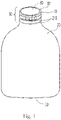
- a container 10 is shown in Fig. 1 .
- the container 10 can be suitable for containing a liquid consumer product 15.
- the liquid consumer product 15 can be selected from the group consisting of liquid laundry detergent, liquid fabric softener, liquid hand soap, liquid body soap, liquid cooking oil, olive oil, liquid skin lotion, liquid hand dish detergent, liquid automatic dish detergent, and liquid surface cleaner.
- a fitment 90 is fitted to the container 10.
- the fitment 10 can be a closure 180 or part of a closure system that includes a spout.
- the fitment can be a flip top closure 200.
- the container body 20 can contain from about 1 to about 5 L of a liquid fabric treatment composition having a density of from about 0.7 to about 1.2 g/cm 3 , optionally from about 0.8 to about 1 g/cm 3 .
- the liquid fabric treatment composition can be a liquid laundry detergent or a liquid fabric enhancer.
- the container 10 described herein can be particularly practical for a container body 20 sized and dimensioned to contain about 1 L to about 5 L or a liquid fabric treatment composition having a density from about 0.7 to about 1.2 g/cm3 since such containers 10 end up having a large amount of momentum when they impact a stationary object, as might happen when such a container 10 is dropped during shipment.
- the high quantity of momentum can result in appreciable stresses on the adhesive 140 that seals the fitment 90 to the neck finish 50 and the adhesives 140 described herein can help to dissipate the force of impact over a longer time, thereby lowering the maximum stress level on the fitment, closure 180 if present, container 20, and adhesive 140.
- the container body 20 can be a thermoplastic container body 20.
- Thermoplastic container bodies 20 can be formed by extrusion blow molding, injection blow molding, compression blow forming, and injection stretch blow molding.
- the fitment 90 can be a thermoplastic fitment 90.
- a thermoplastic fitment 90 can be formed by injection molding.
- the fitment 90 is attached to the container body 20.
- the fitment 90 can be attached to the neck finish 50 at the open end 40 of the container body 20 by a snap fit connection between the fitment 90 and the container body 20.
- An adhesive 140 is provided to affix the fitment 90 to the neck finish 50 of the container body 20.
- a container 10 is shown in greater detail in Fig. 2 .
- the container body 20 has a closed end 30 and an opposing open end 40.
- the container 10 is typically stored by resting the closed end 30 of the container 10 on a flat surface.
- the open end 40 comprises a neck finish 50.
- the neck finish 50 is the structure proximal the top of the container body 20 that is designed such that a fitment 90 can be attached thereto.
- the neck finish 50 and the fitment 90 are designed to fit with one another.
- the neck finish 50 has a longitudinal axis L passing through the open end 40.
- Figure 2 is a partial sectional view in which part of the container body 20 proximal the open end 40 is removed.
- the open end 40 has an inner surface 60 oriented towards the longitudinal axis L. Further, the open end 40 has an outer surface 70 oriented away from the longitudinal axis L. Further, the open end 40 has a top surface 80 extending between the inner surface 60 and outer surface 70.
- a fitment 90 attached to a neck finish 50 is shown in Fig. 3 .
- the fitment 90 is at least partially within the neck finish 50.
- partially within is meant that a portion of the fitment 90 is positioned below the top surface 80. That is, a portion of the fitment 90 is positioned between the top surface 80 and the closed end 30.
- a portion of a fitment 90 that is a closure 180 or a fitment 90 that comprises a spout can be fit down into the open end 40 of the container body 20.
- the fitment 90 comprises an external flange 100 exterior to the neck finish 50. That is the external flange 100 is positioned so the that the neck finish 50 is between external flange 100 and the longitudinal axis L.
- the external flange 100 is the part of the fitment 90 that can be in contact with or attached to the outer surface 70 of the neck finish 50.
- the external flange 100 can circumscribe or partially circumscribe the exterior of the neck finish 50.
- the external flange 100 is downwardly depending towards the closed end 30.
- the fitment 90 can-further comprises an internal flange 110 that is interior to the neck finish 50 and downwardly depending towards the closed end 30. Together, the external flange 100 and the internal flange 11 fit over the neck finish 50.
- the external flange 100 and internal flange 110 are complementary to one another to fit over the neck finish.
- the external flange 100 and internal flange 110 can fit tightly against the neck finish 50.
- the internal flange 110 is part of the fitment 90 that can be in contact with or attached to the inner surface 60 of the neck finish 50.
- the neck finish 50 can circumscribe or partially circumscribe the internal flange 110.
- the fitment 90 further comprises a bridge 120 extending across the top surface 80.
- the bridge 120 is positioned so that the top surface 80 is between the bridge 120 and the closed end 30.
- the bridge 120 extends across the top surface 80 from the external flange 100 to the internal flange 110.
- the external flange 100, bridge 120, and internal flange 110 together form a slot 130 that extends at least partially around or even fully around the longitudinal axis L.
- the neck finish 50 fits into the slot 130.
- the fit may be a tight fit such that a considerable amount of force is required to engage the fitment 90 with the neck finish 50.
- An adhesive 140 is positioned within the slot 130 between the neck finish 50 and the fitment 90.
- the adhesive 140 can positioned so that it is entirely on the top surface 80 of the neck finish 50.
- the adhesive 140 can be positioned so that it is between the external flange 100 and the outer surface 70 of the neck finish 50.
- the adhesive 140 can be positioned so that it is between the internal flange 110 and the inner surface 60 of the neck finish 50.
- the adhesive 140 can extend from between the external flange 100 and the outer surface 70 to between the bridge 120 and the top surface 80 to between the internal flange 110 and the inner surface 60.
- the top surface 80 can be embedded in the adhesive 140. That is, at particular locations around the longitudinal axis L or even all the way around the longitudinal axis L, the adhesive 140 can extend across the top surface 80 between the inner surface 60 and outer surface 70 and at least partially between the external flange 100 and neck finish 50 and at least partially between the internal flange 110 and the neck finish 50. Providing the adhesive 140 such that the entire top surface 80 is embedded in or in contact with the adhesive 140 can provide for a leak resistant seal between the neck finish 50 and the fitment 90.
- providing adhesive 140 that extends from between the external flange 100 and the outer surface 70, across the top surface 80, to between the internal flange 110 and the inner surface 60, can provide for a leak resistant seal between the neck finish 50 and fitment 90 as well has for mechanical engagement between such parts and surfaces.
- the fitment 90 can comprise threads 170 on a surface of the fitment 90 oriented away from the longitudinal axis L.
- the threads 170 can be positioned on a surface of the fitment 90 oriented away from the longitudinal axis L.
- the threads 170 can be positioned on a surface of the fitment 90 oriented towards the longitudinal axis L.
- a closure 180 can be engaged with the fitment 90 by the threads 170.
- the closure 180 can be engaged with threads 170 that are the external flange 100 oriented away from the longitudinal axis L or threads 170 that are on the internal flange 110 oriented towards the longitudinal axis L.
- the container body 20 and fitment 90 are plastic parts that fit together tightly. To further enhance mechanical engagement between the container body 20 and the fitment 90 the two parts can be adhered together.
- the adhesive 140 can help to provide a liquid tight seal between the container body 20 and the fitment 90, particularly if the adhesive 140 forms a continuous seal between the container body 20 and the fitment 90.
- the adhesive 140 may be provide for enhanced mechanical engagement between the container body 20 and the fitment 90.
- the adhesive 140 can help to resist the fitment 90 moving away from the neck finish 50 when tension is applied to the fitment 90 in a direction away from the neck finish 50.
- the adhesive 140 can also help to resist the fitment 90 moving in torsion around the neck finish 50 around the longitudinal axis L if a torsional load is applied to the fitment 90.
- the adhesive 140 can also provide for a cushion between fitment 90 and neck finish 50 if the fitment 90 is subject to compression.
- the adhesive 140 can also provide for a leak resistant seal between the fitment 90 and the neck finish 50.
- the adhesive 140 can be a hot melt adhesive.
- the adhesive 140 can be DURAPRO IFS brand XJF-6-101-4-UV or DURAPRO IFS brand XJF-6-142-4-UV, both available from Durapro, Reading, Pennsylvania, USA.
- the adhesive 140 can help to seal the fitment 90 to the neck finish 50.
- the adhesive 140 can also help to dampen energy transfer between the fitment 90 and the neck finish 50. For example, if the container 10 is dropped such that the fitment is rapidly loaded, as might occur if the container 10 is dropped so that the fitment 90 impacts a rigid surface or impacts the interior of a box in which the container 10 is shipped, the adhesive 140 can dampen the energy transfer from the fitment 90 to the container body 20.
- the adhesive 140 has a TanDelta from 0.65 to about 3.
- the adhesive 140 can have a TanDelta from about 0.7 to about 3.
- the adhesive 140 can have a TanDelta from about 0.75 to about 3.
- the adhesive 140 can have a TanDelta from about 0.8 to about 3.
- the adhesive 140 can have a TanDelta from about 0.85 to about 3.
- the adhesive 140 can have a TanDelta from about 0.9 to about 3.
- the adhesive 140 can have a TanDelta from about 0.95 to about 3.
- the adhesive 140 can have a TanDelta from about 1 to about 3.
- the adhesive 140 can have a TanDelta from about 0.65 to about 2.5.
- the adhesive 140 can have a TanDelta from about 0.7 to about 2.5.
- the adhesive 140 can have a TanDelta from about 0.75 to about 2.5.
- the adhesive 140 can have a TanDelta from about 0.8 to about 2.5.
- the adhesive 140 can have a TanDelta from about 0.85 to about 2.5.
- the adhesive 140 can have a TanDelta from about 0.9 to about 2.5.
- the adhesive 140 can have a TanDelta from about 0.95 to about 2.5.
- the adhesive 140 can have a TanDelta from about 0.98 to about 2.33, or even 0.98 to 2.33.
- the adhesive 140 can have a TanDelta from about 1 to about 2.5.
- Delta is an expression of the phase shift between applied stress and the material response. Delta can theoretically range from 0 degrees for a perfectly elastic material to 90 degrees for a perfectly viscous material. Thus, low values of TanDelta, which is the tangent of delta, are associated with more elastic materials and higher values of TanDelta are associated with more viscous materials.
- Adhesives that have too low of a TanDelta tend to respond as an elastic material. Such adhesives tend not dampen impacts appreciably. Further such adhesives may be stiff and or brittle. Containers that have a fitment attached to the container body with an adhesive having a low value of TanDelta will tend to leak and or possibly crack when shipped through direct to consumer channels. Without being bound by theory, it is thought that designers of containers having a fitment attached to the container body with an adhesive have tended to focus on using adhesives that tend to respond in a manner more towards the behavior of an elastic material.
- TanDelta of adhesive 140 is measured according to the TanDelta Test Method disclosed herein.
- the neck finish 50 can be provided with one or more neck teeth 210 that engage with one or more flange teeth, by way of a non-limiting example is shown in Fig. 4 .
- the neck teeth 210 can be provided on the outer surface 70 of the neck finish 50.
- the neck teeth 210 can be oriented away from the longitudinal axis L.
- the external flange 100 can be provided with one or more flange teeth 220, by way of non-limiting example as shown in Fig. 5.
- Figure 5 is a bottom view of a fitment 90.
- the neck teeth 210 and flange teeth 220 can be complementary to one another.
- the neck teeth 210 and flange teeth 220 can interlock with one another.
- the neck teeth 210 and flange teeth 220 can tightly interlock with one another.
- Interlocking teeth can help to provide the connection between the fitment 90 and the neck finish 50 with resistance to torsional loads applied across the interface between these two element.
- a lug and notch complementary structure can be used in the same locations and for the same purposes as the teeth.
- the interlocking teeth can provide a back stop on rotation of the fitment 90 about the neck finish 50.
- the adhesive 140 may be able to resist torsional loads with an acceptable amount of strain up to some limit. Beyond that strain, the adhesive 140 may fail or yield an excessive amount.
- the adhesive 140 may also provide for resistance to leakage between the neck finish 50 and the fitment 90 so long as the strain is not excessive.
- the tolerance of the fit between the neck teeth 210 and the flange teeth 220 can be set so that the teeth engage with one another before the torsional movement of the teeth relative to one another exceeds an amount such that the mechanical and or sealing integrity of the adhesive 140 is degraded.
- the teeth can fit together tightly, that is have a low tolerance fit, so that little torsional movement of the fitment 90 relative to the neck finish 50 is permitted under anticipated torsional loads.
- the interlocking teeth can be shaped to be more resistant to torsion applied in one rotational direction than the other. That might be practical if the fitment 90 is a part having threads to which a closure 180 having cooperating threads is rotationally secured thereto.
- the teeth may be sized and dimensioned to resist clockwise torsion about the longitudinal axis L as viewed from above the open end 40.
- a top view of the container body 20 is shown in Fig. 6 .
- the neck finish 50 can present as an annulus in this view.
- the top surface 80 can have a peripheral length 190 around the longitudinal axis L.
- the peripheral length 190 is the length of the top surface measured along the top surface 80 where the top surface 80 meets the external surface 270.
- the peripheral length is pi multiplied by the outside diameter of the open end 40.
- the mass of adhesive 140 per millimeter of the peripheral length 190 is the average mass of adhesive 140 per millimeter of the peripheral length 190. It is the measure of the total mass of adhesive 140 between the fitment 90 and the neck finish 50 divided by the peripheral length 190.
- the fitment 90 can comprise threads 170 on the external flange 100 oriented away from the longitudinal axis L, by way of non-limiting example as shown in Fig. 7 . Such an arrangement can be practical for providing a closure 180 that covers or partially covers the fitment 90.
- the fitment 90 can comprise threads 170 on the internal flange 110 oriented towards the longitudinal axis L, as shown in Fig. 8 .
- the threads 170 on the internal flange 110 can be sized and dimensioned to receive corresponding threads 170 located on a surface of the closure 180 oriented away from the longitudinal axis L.
- the closure 180 can be a flange seal closure 180. That is, there can be a peripheral flange 230 that flexes and fits tightly up against the fitment 90 to seal the container body 20 closed.
- the container 10 comprises the container body 20, the fitment 90 attached to the neck finish 50, the adhesive 140, the fitment 90, and the closure 180 screwed into the fitment 90.
- the fitment 90 can further comprise a spout 150 engaged with the internal flange 110, wherein said spout extends upwardly away from the closed end 30, by way of non-limiting example as shown in Fig. 9 .
- the spout 150 can be positioned around the longitudinal axis L. It can be practical to provide a fitment 90 that is a spout 150 to help the consumer precisely dispense liquid consumer product 15 from the container body 20.
- the fitment 90 and closure 180 can be injection molded parts.
- the tolerances with which injection molded parts can be made can be exacting.
- the closure 180 can seal tightly to the fitment 90, for example by way of the threads pulling the closure 180 more tightly up against the fitment 90 as the closure 180 is rotated.
- Extrusion blow mold container bodies 20 are relatively simple and inexpensive to make. Gluing the fitment 90 to the neck finish 50 of an extrusion blow molded container body 20 can provide for a mechanically strong connection between the fitment 90 and the container body 20. And gluing the fitment 90 to the neck finish 50 can provide a leak resistant connection.
- the fitment 90 can further comprise a floor 160 extending at least partially around the longitudinal axis L and connect the spout 150 to the internal flange 110.
- the floor 160 can be sloped back to a slot or hole through which liquid consumer product 15 that might drip from the tip 240 of the spout can be caught on the floor 160 and drain back into the container body 20.
- the fitment 90 and the neck finish 50 can each have geometry that cooperates with the other to provide for a snap together fit of the two components.
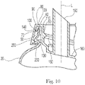
- a nonlimiting example of the fit of a fitment 90 and neck finish 50 is shown in Fig. 10 .
- the outer surface 70 and the external flange 100 can be spaced apart from one another by from about 0.2 mm to about 5 mm, or even about 1 mm.
- the inner surface 60 and the internal flange 110 can be spaced apart from one another by from about 0.2 mm to about 5 mm, or even about 2 mm.
- the top surface 80 and the bridge 120 can be spaced apart from one another by from about 0.2 mm to about 5 mm, or even about 2 mm.
- the fitment 90 can be provided with a catch 250 protruding from the external flange 100 towards the longitudinal axis L.
- the catch 250 can extend circumferentially or partially circumferentially about the longitudinal axis L.
- the catch 250 can positioned, sized, and dimensioned to fit with a rib 260 in the neck finish oriented away from the longitudinal axis L.
- the catch 250 can protrude from the external flange 100 by about 2 mm.
- the rib 260 can extend circumferentially or partially circumferentially about the longitudinal axis L.
- the rib 260 can project away from the upper part of the neck finish by about 2 mm.
- the catch 250 and rib 260 can function to provide resistance the fitment 90 and neck finish 50 from being pulled apart in the longitudinal direction and to hold the fitment 90 in the proper place as the adhesive 140 hardens.
- the fit of the fitment 90 and neck finish 50 can be sized and dimensioned so that the slot 130 is spacious enough so that the adhesive 140 can be continuous from the space between the external flange 100 and outer surface 70 through the space between the bridge 120 and the top surface 80 to the space between the internal flange 110 and the inner surface 60.
- the adhesive 140 can act as a cushion to dampen the impact force of the container 10 being dropped which can reduce the potential for the fitment 90 or closure 180 attached to the fitment 90, if provided, to crack under impact. Further the adhesive 140 can provide a leak resistant seal between the fitment 90 and the neck finish 50.
- Adhesive 140 can be applied in the slot 130 in a molten state.
- the adhesive 140 can be applied using a nozzle.
- the nozzle and fitment 90 can move relative to one another so that adhesive is provide around the entire or a portion of the slot 130.
- the nozzle can move around the fitment 90 or the fitment 90 can be rotated underneath a stationary nozzle.
- the adhesive 140 can be applied in a single pass or multiple passes. It can be practical to apply the adhesive 140 at a temperature from about 110 C to about 150 C, optionally from about 127 C to about 132 C.
- the container body 20, fitment 90, and closure 180 can be of the type in which TIDE liquid laundry detergent or DOWNY liquid fabric softener is sold by the The Procter & Gamble Company, Cincinnati, Ohio, United States of America, as of the filing date of this specification, an example of which is shown in Fig. 11 .
- Test Project 6-Amazon.com-Over Boxing is a general simulation test for e-Commerce fulfillment.
- this kind of e-Commerce fulfillment comprises an individual retail packaged-product weighing 70 pounds (32 kilograms) or less being placed into a master shipping container (Over Box) either by itself with the addition of dunnage (air pillows, etc.) or with multiple individual retail packagedproducts with dunnage for shipment from Amazon.com to an end consumer through a parcel delivery system.
- This test challenges the packaging and/or products, whether primary package or transport package, ability to withstand the general damage-producing motions, forces, conditions, and sequences of this environment.
- the single item test is intended to represent shipment of a single container in a box.
- the multiple item test is intended to represent shipment of a single container and 2 additional articles within a box.
- the container design tested in the tests was the 2.94 L TIDE liquid detergent having the container design used in the United States as of the filing date of this specification. Approximately 2 g of the adhesive tested was placed in the slot of the fitment. The container was closed with a closure screwed into the fitment. The fitment included a spout. An image of the neck finish, the fitment, and closure representative of the design of the container tested is shown in Fig. 11 .
- the over box was a 35.56 cm by 20.32 cm by 20.32 cm ULINE S-4139 box.
- the box was filled with a 2.94 L bottle of TIDE liquid detergent available from The Procter & Gamble Company, Cincinnati, OH, USA, and ULINE inflatable cellular air pillow cushioning S-12881 available from ULINE, Pleasant Prairie, Wisconsin, USA.
- the bottle was placed in the over box with the closure contacting face 4 and face 6 following the ISTA procedures.
- the air pillows were loosely packed in the box and the box was taped closed. Four single item samples were tested.
- the over box was 45.72 cm by 22.86 cm by 22.86 cm ULINE S4632 box.
- the box was filled with a 2.94 L bottle of TIDE liquid detergent.
- An F-sized hazard 102 mm by 102 mm by 102 mm having a mass of 1.36 kg and a G-sized hazard 102 mm by 76 mm by 51 mm having a mass of 1.59 kg were included in the box.
- ULINE inflatable cellular air pillow cushioning S-12881 were loosely packed in the box and the box and the box was taped closed. Six multiple item samples were tested.
- Table 1 International Safe Transit Association (ISTA) Project 6-AMAZON.COM-Over Boxing, e-Commerce Fulfillment for Parcel Delivery Shipment Test Results.
- IFS 101-4 from Durapro, Reading, Pennsylvania, USA 2.33 0 out of 10 1 out of 10 Small leak detected with water and soap solution deemed not to be consumer objectionable IFS 142-4 from Durapro, Reading, Pennsylvania, USA 1.17 0 out of 10 1 out of 10 Slow leak deemed not to be consumer objectionable Valco Melton 8056 from Valco Melton, Cincinnati, Ohio, USA 0.98 0 out of 10 1 out of 10 Slow leak deemed not to be consumer objectionable ASI 4055M from Adhesives Specialists Incorporated, Allentown, Pennsylvania, USA (used in the container for TIDE liquid laundry detergent in the United States as of the filing date of this specification) 0.56 1 out of 10 2 out of 10 Transition shattered, transition leaks severe,
- the TanDelta test method is a dynamic mechanical analysis (DMA) used to determine a rheological parameter termed "TanDelta" (tan ⁇ ), which may also be known as the tangent of delta, the loss tangent, the loss factor, the damping factor, or the tangent of the phase angle.
- the TanDelta value is a parameter that characterizes the viscoelastic nature of a material, including materials such as a glue or a thermoplastic which may be used for gluing a fitment to a container body.
- Dynamic stress-strain testing measurements for the determination of TanDelta are made with a DMA Analyzer such as the model RSA-G2 Solids Analyzer (available from TA Instruments, New Castle, Delaware, U.S.A.) or equivalent, and the manufacturer's accompanying software.
- the DMA instrument is configured with 25.4 mm diameter parallel compression plates and a temperature-controlling environmental chamber which surrounds the sample.
- the DMA instrument is configured to collect data during cyclical compression testing with mode settings of strain-controlled, fixed-frequency, and axial-application. The instrument is calibrated in accordance with the manufacturer's recommendations.
- a test sample of glue material may be obtained from an emptied and thoroughly cleaned assembled container by physically cutting the container to separate the bulk of the container material away from the relevant glue-containing portion (e.g., the closure or transition piece).
- the glue containing portion is then placed in an oven set to a temperature that is above the melting point of the glue (e.g. 93 °C may be a suitable temperature for some glues).
- a suitable temperature can be determined empirically by observing and comparing the softness of the glue at various temperatures. Once the glue has softened due to the heat of the oven, the glue is removed from the packaging by scraping with a small spatula. In order to obtain a sufficient amount of test sample for analysis, several assembled package containers may need to be processed in this manner and the harvested glue pooled together.
- the glue to be tested is warmed sufficiently to enable the test sample to be formed into a sample disc shape having dimensions of 25.4 mm in diameter and 2 mm in thickness.
- a 25.4 mm diameter casting mold or die cutter ring may be helpful to achieve the correct dimensions for the sample disc. It is important that bubbles are excluded from the sample disc during its preparation.
- the Environmental Control is set with a Temperature of 23 °C; Equilibrium is set with a Perform Equilibration selected as On; and Equilibrium Duration is set to 600 s. Wait for Temperature is selected as On; Mode is set to Standard CyclicCompression Strain; CompressionRate Frequency is set to 100 Hz; Strain is set to 0.02 % of the gap distance; Duration is set to 10,000 repetitions; the preload force is set at 5 N; Inherit Set Point is selected as Off; Soak Time is set to 0.0 s.
- the DMA plates are cleaned with isopropanol and the solvent is allowed to evaporate away.
- the sample disc is loaded onto the center surface of the 25.4 mm diameter plate.
- the temperature is monitored to ensure that the environmental sample chamber reaches the set temperature of 23°C.
- the sample disc is equilibrated to 23 °C prior to the start of data collection.
- the plate is lowered to a preload force set at 5 N.
- the gap distance is recorded. It is important to ensure that the sample disc is evenly distributed around the edge of the plates.
- TanDelta tan ⁇ E " / E ′
- E ′ c o s ⁇ ⁇ / ⁇
- E " s i n ⁇ ⁇ / ⁇
- TanDelta value reported for the material is the average of the three median values measured from the three replicate sample discs.
- the resultant average TanDelta value reported is a unitless expression.
Landscapes
- Engineering & Computer Science (AREA)
- Mechanical Engineering (AREA)
- Closures For Containers (AREA)
- Details Of Rigid Or Semi-Rigid Containers (AREA)
Description
- Consumers are increasingly demanding to have consumer products shipped directly to their household. This is particularly true for heavy liquid consumer products such as liquid laundry detergent, liquid fabric softener, hand and body soap, cooking oil, olive oil, and the like. Shipping liquid products directly to the consumer is a challenging task due to the rough handling that might occur to the product during transfer of the liquid product from the manufacturer to the consumer. Rough handling can impart stresses on the container that are much greater than might occur in traditional retail shipping channels from the manufacturer to the retailer.
- Manufacturers of liquid consumer products prefer to use the same container designs in both retail trade channels and direct to consumer channels. This simplifies production and management of inventory for the manufacturer. For many liquid consumer products, the preferred container is an extrusion blow molded container body and a fitment. The fitment may be a closure, such as a flip top closure, or a spout having a drain-back feature with the fitment configured to receive a closure.
- Blow molded container bodies to which a fitment is attached are subject to leaking between the container body and the fitment during direct shipping to the consumer. A costly answer to this problem would be to employ a blow molded container body having calibrated neck and a plug seal fitment. Such a container body may be over-designed for the retail channel of trade, and thus be overly expensive. Providing additional cushioning and or placing the container in a sealed bag within the box and or shrink sleeving the entire container are other approaches for solving the problem, all which add additional cost to the manufacturer.
- With these limitations in mind, there is a continuing unaddressed need for a container for liquid products that has a fitment attached thereto that is resistant to leakage during transport in different channels of trade.
-
US5174460A discloses a dual seal closure-adaptor.US200/05087548A1 discloses a drain-back snap-on pour spout fitment closure.US4533058A discloses a one-piece thermoplastic child-resistent dispensing closure. - A container (10) according to claim 1 comprising: a container body (20) having a closed end (30) and an opposing open end (40), wherein said open end comprises a neck finish (50) having a longitudinal axis (L) passing through said open end, an inner surface (60) oriented towards said longitudinal axis, an outer surface (70) oriented away from said longitudinal axis, and a top surface (80) extending between said inner surface and said outer surface; a fitment (90) fitted at least partially within said neck finish, said fitment comprising an external flange (100) exterior to said neck finish and downwardly depending towards said closed end, an internal flange (110) interior to said neck finish and downwardly depending towards said closed end, and a bridge (120) extending across said top surface from said external flange to said internal flange, wherein said external flange, said bridge, and said internal flange together form a slot (130) extending at least partially around said longitudinal axis; and an adhesive (140) positioned within said slot between said neck finish and said fitment, wherein said adhesive has a TanDelta from 0.65 to 3.
-
-
Figure 1 is a container. -
Figure 2 is a container body. -
Figure 3 is a fitment attached to a neck finish, part of the container body being shown. -
Figure 4 is a container body having a neck finish. -
Figure 5 is a bottom view of a fitment. -
Figure 6 is a top view of a container body. -
Figure 7 is a cross section of a fitment to which a closure is attached, an upper part of the container body is shown. -
Figure 8 is a cross section of a fitment attached to a neck finish and a closure positioned to be ready to attach to the fitment, an upper part of the container body is shown. -
Figure 9 is a cross section of a fitment that includes a spout. -
Figure 10 is a cross section of a fitment that includes a spout, the fitment attached to a neck finish. -
Figure 11 is an image neck finish, a fitment including a spout, and a closure representative of the container tested following International Safe Transit Association (ISTA) Project 6-AMAZON.COM-Over Boxing, e-Commerce Fulfillment for Parcel Delivery Shipment, last technical change August, 2016, Sequence Number 3. - A
container 10 is shown inFig. 1 . Thecontainer 10 can be suitable for containing aliquid consumer product 15. Theliquid consumer product 15 can be selected from the group consisting of liquid laundry detergent, liquid fabric softener, liquid hand soap, liquid body soap, liquid cooking oil, olive oil, liquid skin lotion, liquid hand dish detergent, liquid automatic dish detergent, and liquid surface cleaner. Afitment 90 is fitted to thecontainer 10. Thefitment 10 can be aclosure 180 or part of a closure system that includes a spout. The fitment can be a fliptop closure 200. Thecontainer body 20 can contain from about 1 to about 5 L of a liquid fabric treatment composition having a density of from about 0.7 to about 1.2 g/cm3, optionally from about 0.8 to about 1 g/cm3. The liquid fabric treatment composition can be a liquid laundry detergent or a liquid fabric enhancer. Thecontainer 10 described herein can be particularly practical for acontainer body 20 sized and dimensioned to contain about 1 L to about 5 L or a liquid fabric treatment composition having a density from about 0.7 to about 1.2 g/cm3 sincesuch containers 10 end up having a large amount of momentum when they impact a stationary object, as might happen when such acontainer 10 is dropped during shipment. The high quantity of momentum can result in appreciable stresses on the adhesive 140 that seals thefitment 90 to theneck finish 50 and theadhesives 140 described herein can help to dissipate the force of impact over a longer time, thereby lowering the maximum stress level on the fitment,closure 180 if present,container 20, and adhesive 140. - The
container body 20 can be athermoplastic container body 20.Thermoplastic container bodies 20 can be formed by extrusion blow molding, injection blow molding, compression blow forming, and injection stretch blow molding. Similarly, thefitment 90 can be athermoplastic fitment 90. Athermoplastic fitment 90 can be formed by injection molding. - The
fitment 90 is attached to thecontainer body 20. Thefitment 90 can be attached to theneck finish 50 at theopen end 40 of thecontainer body 20 by a snap fit connection between thefitment 90 and thecontainer body 20. An adhesive 140 is provided to affix thefitment 90 to theneck finish 50 of thecontainer body 20. - A
container 10 is shown in greater detail inFig. 2 . Thecontainer body 20 has a closedend 30 and an opposingopen end 40. In use, thecontainer 10 is typically stored by resting the closedend 30 of thecontainer 10 on a flat surface. Theopen end 40 comprises aneck finish 50. Theneck finish 50 is the structure proximal the top of thecontainer body 20 that is designed such that afitment 90 can be attached thereto. The neck finish 50 and thefitment 90 are designed to fit with one another. - The
neck finish 50 has a longitudinal axis L passing through theopen end 40.Figure 2 is a partial sectional view in which part of thecontainer body 20 proximal theopen end 40 is removed. Theopen end 40 has aninner surface 60 oriented towards the longitudinal axis L. Further, theopen end 40 has anouter surface 70 oriented away from the longitudinal axis L. Further, theopen end 40 has atop surface 80 extending between theinner surface 60 andouter surface 70. - Part of a
fitment 90 attached to aneck finish 50 is shown inFig. 3 . Thefitment 90 is at least partially within theneck finish 50. By partially within it is meant that a portion of thefitment 90 is positioned below thetop surface 80. That is, a portion of thefitment 90 is positioned between thetop surface 80 and the closedend 30. A portion of afitment 90 that is aclosure 180 or afitment 90 that comprises a spout can be fit down into theopen end 40 of thecontainer body 20. - The
fitment 90 comprises anexternal flange 100 exterior to theneck finish 50. That is theexternal flange 100 is positioned so the that theneck finish 50 is betweenexternal flange 100 and the longitudinal axis L. Theexternal flange 100 is the part of thefitment 90 that can be in contact with or attached to theouter surface 70 of theneck finish 50. Theexternal flange 100 can circumscribe or partially circumscribe the exterior of theneck finish 50. Theexternal flange 100 is downwardly depending towards theclosed end 30. - The
fitment 90 can-further comprises aninternal flange 110 that is interior to theneck finish 50 and downwardly depending towards theclosed end 30. Together, theexternal flange 100 and the internal flange 11 fit over theneck finish 50. Theexternal flange 100 andinternal flange 110 are complementary to one another to fit over the neck finish. Theexternal flange 100 andinternal flange 110 can fit tightly against theneck finish 50. Theinternal flange 110 is part of thefitment 90 that can be in contact with or attached to theinner surface 60 of theneck finish 50. Theneck finish 50 can circumscribe or partially circumscribe theinternal flange 110. - The
fitment 90 further comprises abridge 120 extending across thetop surface 80. Thebridge 120 is positioned so that thetop surface 80 is between thebridge 120 and theclosed end 30. Thebridge 120 extends across thetop surface 80 from theexternal flange 100 to theinternal flange 110. Theexternal flange 100,bridge 120, andinternal flange 110 together form aslot 130 that extends at least partially around or even fully around the longitudinal axis L. Theneck finish 50 fits into theslot 130. The fit may be a tight fit such that a considerable amount of force is required to engage thefitment 90 with theneck finish 50. - An adhesive 140 is positioned within the
slot 130 between theneck finish 50 and thefitment 90. The adhesive 140 can positioned so that it is entirely on thetop surface 80 of theneck finish 50. Optionally, the adhesive 140 can be positioned so that it is between theexternal flange 100 and theouter surface 70 of theneck finish 50. The adhesive 140 can be positioned so that it is between theinternal flange 110 and theinner surface 60 of theneck finish 50. The adhesive 140 can extend from between theexternal flange 100 and theouter surface 70 to between thebridge 120 and thetop surface 80 to between theinternal flange 110 and theinner surface 60. - The
top surface 80 can be embedded in the adhesive 140. That is, at particular locations around the longitudinal axis L or even all the way around the longitudinal axis L, the adhesive 140 can extend across thetop surface 80 between theinner surface 60 andouter surface 70 and at least partially between theexternal flange 100 andneck finish 50 and at least partially between theinternal flange 110 and theneck finish 50. Providing the adhesive 140 such that the entiretop surface 80 is embedded in or in contact with the adhesive 140 can provide for a leak resistant seal between theneck finish 50 and thefitment 90. Further, providing adhesive 140 that extends from between theexternal flange 100 and theouter surface 70, across thetop surface 80, to between theinternal flange 110 and theinner surface 60, can provide for a leak resistant seal between theneck finish 50 andfitment 90 as well has for mechanical engagement between such parts and surfaces. - As shown in
Fig. 3 , thefitment 90 can comprisethreads 170 on a surface of thefitment 90 oriented away from the longitudinal axis L. Such an arrangement is practical if theclosure 180 screws onto theneck finish 50. Thethreads 170 can be positioned on a surface of thefitment 90 oriented away from the longitudinal axis L. Optionally, thethreads 170 can be positioned on a surface of thefitment 90 oriented towards the longitudinal axis L. Aclosure 180 can be engaged with thefitment 90 by thethreads 170. Theclosure 180 can be engaged withthreads 170 that are theexternal flange 100 oriented away from the longitudinal axis L orthreads 170 that are on theinternal flange 110 oriented towards the longitudinal axis L. - Typically the
container body 20 andfitment 90 are plastic parts that fit together tightly. To further enhance mechanical engagement between thecontainer body 20 and thefitment 90 the two parts can be adhered together. The adhesive 140 can help to provide a liquid tight seal between thecontainer body 20 and thefitment 90, particularly if the adhesive 140 forms a continuous seal between thecontainer body 20 and thefitment 90. Optionally, if the adhesive 140 is discontinuous, the adhesive 140 may be provide for enhanced mechanical engagement between thecontainer body 20 and thefitment 90. - The adhesive 140 can help to resist the
fitment 90 moving away from theneck finish 50 when tension is applied to thefitment 90 in a direction away from theneck finish 50. The adhesive 140 can also help to resist thefitment 90 moving in torsion around theneck finish 50 around the longitudinal axis L if a torsional load is applied to thefitment 90. The adhesive 140 can also provide for a cushion betweenfitment 90 andneck finish 50 if thefitment 90 is subject to compression. The adhesive 140 can also provide for a leak resistant seal between thefitment 90 and theneck finish 50. - The adhesive 140 can be a hot melt adhesive. The adhesive 140 can be DURAPRO IFS brand XJF-6-101-4-UV or DURAPRO IFS brand XJF-6-142-4-UV, both available from Durapro, Reading, Pennsylvania, USA. The adhesive 140 can help to seal the
fitment 90 to theneck finish 50. The adhesive 140 can also help to dampen energy transfer between thefitment 90 and theneck finish 50. For example, if thecontainer 10 is dropped such that the fitment is rapidly loaded, as might occur if thecontainer 10 is dropped so that thefitment 90 impacts a rigid surface or impacts the interior of a box in which thecontainer 10 is shipped, the adhesive 140 can dampen the energy transfer from thefitment 90 to thecontainer body 20. - The adhesive 140 has a TanDelta from 0.65 to about 3. The adhesive 140 can have a TanDelta from about 0.7 to about 3. The adhesive 140 can have a TanDelta from about 0.75 to about 3. The adhesive 140 can have a TanDelta from about 0.8 to about 3. The adhesive 140 can have a TanDelta from about 0.85 to about 3. The adhesive 140 can have a TanDelta from about 0.9 to about 3. The adhesive 140 can have a TanDelta from about 0.95 to about 3. The adhesive 140 can have a TanDelta from about 1 to about 3. The adhesive 140 can have a TanDelta from about 0.65 to about 2.5. The adhesive 140 can have a TanDelta from about 0.7 to about 2.5. The adhesive 140 can have a TanDelta from about 0.75 to about 2.5. The adhesive 140 can have a TanDelta from about 0.8 to about 2.5. The adhesive 140 can have a TanDelta from about 0.85 to about 2.5. The adhesive 140 can have a TanDelta from about 0.9 to about 2.5. The adhesive 140 can have a TanDelta from about 0.95 to about 2.5. The adhesive 140 can have a TanDelta from about 0.98 to about 2.33, or even 0.98 to 2.33. The adhesive 140 can have a TanDelta from about 1 to about 2.5.
- Delta is an expression of the phase shift between applied stress and the material response. Delta can theoretically range from 0 degrees for a perfectly elastic material to 90 degrees for a perfectly viscous material. Thus, low values of TanDelta, which is the tangent of delta, are associated with more elastic materials and higher values of TanDelta are associated with more viscous materials.
- Adhesives that have too low of a TanDelta tend to respond as an elastic material. Such adhesives tend not dampen impacts appreciably. Further such adhesives may be stiff and or brittle. Containers that have a fitment attached to the container body with an adhesive having a low value of TanDelta will tend to leak and or possibly crack when shipped through direct to consumer channels. Without being bound by theory, it is thought that designers of containers having a fitment attached to the container body with an adhesive have tended to focus on using adhesives that tend to respond in a manner more towards the behavior of an elastic material.
- TanDelta of adhesive 140 is measured according to the TanDelta Test Method disclosed herein.
- The
neck finish 50 can be provided with one ormore neck teeth 210 that engage with one or more flange teeth, by way of a non-limiting example is shown inFig. 4 . Theneck teeth 210 can be provided on theouter surface 70 of theneck finish 50. Theneck teeth 210 can be oriented away from the longitudinal axis L. - The
external flange 100 can be provided with one ormore flange teeth 220, by way of non-limiting example as shown inFig. 5. Figure 5 is a bottom view of afitment 90. Theneck teeth 210 andflange teeth 220 can be complementary to one another. Theneck teeth 210 andflange teeth 220 can interlock with one another. Optionally, theneck teeth 210 andflange teeth 220 can tightly interlock with one another. Interlocking teeth can help to provide the connection between thefitment 90 and theneck finish 50 with resistance to torsional loads applied across the interface between these two element. A lug and notch complementary structure can be used in the same locations and for the same purposes as the teeth. - The interlocking teeth can provide a back stop on rotation of the
fitment 90 about theneck finish 50. The adhesive 140 may be able to resist torsional loads with an acceptable amount of strain up to some limit. Beyond that strain, the adhesive 140 may fail or yield an excessive amount. The adhesive 140 may also provide for resistance to leakage between theneck finish 50 and thefitment 90 so long as the strain is not excessive. The tolerance of the fit between theneck teeth 210 and theflange teeth 220 can be set so that the teeth engage with one another before the torsional movement of the teeth relative to one another exceeds an amount such that the mechanical and or sealing integrity of the adhesive 140 is degraded. Optionally, the teeth can fit together tightly, that is have a low tolerance fit, so that little torsional movement of thefitment 90 relative to theneck finish 50 is permitted under anticipated torsional loads. - The interlocking teeth can be shaped to be more resistant to torsion applied in one rotational direction than the other. That might be practical if the
fitment 90 is a part having threads to which aclosure 180 having cooperating threads is rotationally secured thereto. The teeth may be sized and dimensioned to resist clockwise torsion about the longitudinal axis L as viewed from above theopen end 40. - A top view of the
container body 20 is shown inFig. 6 . Theneck finish 50 can present as an annulus in this view. Thetop surface 80 can have aperipheral length 190 around the longitudinal axis L. Theperipheral length 190 is the length of the top surface measured along thetop surface 80 where thetop surface 80 meets theexternal surface 270. For acircular neck finish 50, the peripheral length is pi multiplied by the outside diameter of theopen end 40. For thinwalled container bodies 20, there is little difference between the length of the periphery of thetop surface 80 as measured along the location where thetop surface 80 meets theinternal surface 60 and theperipheral length 190. - There can be from about 0.001 to about 0.1 mg of adhesive 140 per millimeter of the
peripheral length 190. The mass of adhesive 140 per millimeter of theperipheral length 190 is the average mass of adhesive 140 per millimeter of theperipheral length 190. It is the measure of the total mass of adhesive 140 between thefitment 90 and theneck finish 50 divided by theperipheral length 190. - The
fitment 90 can comprisethreads 170 on theexternal flange 100 oriented away from the longitudinal axis L, by way of non-limiting example as shown inFig. 7 . Such an arrangement can be practical for providing aclosure 180 that covers or partially covers thefitment 90. - The
fitment 90 can comprisethreads 170 on theinternal flange 110 oriented towards the longitudinal axis L, as shown inFig. 8 . Thethreads 170 on theinternal flange 110 can be sized and dimensioned to receive correspondingthreads 170 located on a surface of theclosure 180 oriented away from the longitudinal axis L. - The
closure 180 can be aflange seal closure 180. That is, there can be a peripheral flange 230 that flexes and fits tightly up against thefitment 90 to seal thecontainer body 20 closed. In such an arrangement, thecontainer 10 comprises thecontainer body 20, thefitment 90 attached to theneck finish 50, the adhesive 140, thefitment 90, and theclosure 180 screwed into thefitment 90. - The
fitment 90 can further comprise aspout 150 engaged with theinternal flange 110, wherein said spout extends upwardly away from theclosed end 30, by way of non-limiting example as shown inFig. 9 . Thespout 150 can be positioned around the longitudinal axis L. It can be practical to provide afitment 90 that is aspout 150 to help the consumer precisely dispenseliquid consumer product 15 from thecontainer body 20. - The
fitment 90 andclosure 180 can be injection molded parts. The tolerances with which injection molded parts can be made can be exacting. Theclosure 180 can seal tightly to thefitment 90, for example by way of the threads pulling theclosure 180 more tightly up against thefitment 90 as theclosure 180 is rotated. Extrusion blowmold container bodies 20 are relatively simple and inexpensive to make. Gluing thefitment 90 to theneck finish 50 of an extrusion blow moldedcontainer body 20 can provide for a mechanically strong connection between thefitment 90 and thecontainer body 20. And gluing thefitment 90 to theneck finish 50 can provide a leak resistant connection. - The
fitment 90 can further comprise afloor 160 extending at least partially around the longitudinal axis L and connect thespout 150 to theinternal flange 110. Thefloor 160 can be sloped back to a slot or hole through whichliquid consumer product 15 that might drip from the tip 240 of the spout can be caught on thefloor 160 and drain back into thecontainer body 20. - The
fitment 90 and theneck finish 50 can each have geometry that cooperates with the other to provide for a snap together fit of the two components. A nonlimiting example of the fit of afitment 90 andneck finish 50 is shown inFig. 10 . Theouter surface 70 and theexternal flange 100 can be spaced apart from one another by from about 0.2 mm to about 5 mm, or even about 1 mm. Theinner surface 60 and theinternal flange 110 can be spaced apart from one another by from about 0.2 mm to about 5 mm, or even about 2 mm. Thetop surface 80 and thebridge 120 can be spaced apart from one another by from about 0.2 mm to about 5 mm, or even about 2 mm. - The
fitment 90 can be provided with acatch 250 protruding from theexternal flange 100 towards the longitudinal axis L. Thecatch 250 can extend circumferentially or partially circumferentially about the longitudinal axis L. Thecatch 250 can positioned, sized, and dimensioned to fit with arib 260 in the neck finish oriented away from the longitudinal axis L. Thecatch 250 can protrude from theexternal flange 100 by about 2 mm. Therib 260 can extend circumferentially or partially circumferentially about the longitudinal axis L. Therib 260 can project away from the upper part of the neck finish by about 2 mm. Thecatch 250 andrib 260 can function to provide resistance thefitment 90 andneck finish 50 from being pulled apart in the longitudinal direction and to hold thefitment 90 in the proper place as the adhesive 140 hardens. - The fit of the
fitment 90 andneck finish 50 can be sized and dimensioned so that theslot 130 is spacious enough so that the adhesive 140 can be continuous from the space between theexternal flange 100 andouter surface 70 through the space between thebridge 120 and thetop surface 80 to the space between theinternal flange 110 and theinner surface 60. The adhesive 140 can act as a cushion to dampen the impact force of thecontainer 10 being dropped which can reduce the potential for thefitment 90 orclosure 180 attached to thefitment 90, if provided, to crack under impact. Further the adhesive 140 can provide a leak resistant seal between thefitment 90 and theneck finish 50. - Adhesive 140 can be applied in the
slot 130 in a molten state. The adhesive 140 can be applied using a nozzle. The nozzle andfitment 90 can move relative to one another so that adhesive is provide around the entire or a portion of theslot 130. The nozzle can move around thefitment 90 or thefitment 90 can be rotated underneath a stationary nozzle. The adhesive 140 can be applied in a single pass or multiple passes. It can be practical to apply the adhesive 140 at a temperature from about 110 C to about 150 C, optionally from about 127 C to about 132 C. - The
container body 20,fitment 90, andclosure 180 can be of the type in which TIDE liquid laundry detergent or DOWNY liquid fabric softener is sold by the The Procter & Gamble Company, Cincinnati, Ohio, United States of America, as of the filing date of this specification, an example of which is shown inFig. 11 . - Laboratory testing was performed to evaluate the performance of
various adhesives 140 for gluing afitment 90 to aneck finish 50. Testing was conducted following International Safe Transit Association (ISTA) Project 6-AMAZON.COM-Over Boxing, e-Commerce Fulfillment for Parcel Delivery Shipment, last technical change August, 2016, Sequence Number 3. Test Project 6-Amazon.com-Over Boxing is a general simulation test for e-Commerce fulfillment. In comparison to items ready to ship in its own packaging (Test Project 6-Amazon.com- SIOC), this kind of e-Commerce fulfillment comprises an individual retail packaged-product weighing 70 pounds (32 kilograms) or less being placed into a master shipping container (Over Box) either by itself with the addition of dunnage (air pillows, etc.) or with multiple individual retail packagedproducts with dunnage for shipment from Amazon.com to an end consumer through a parcel delivery system. This test challenges the packaging and/or products, whether primary package or transport package, ability to withstand the general damage-producing motions, forces, conditions, and sequences of this environment. - For each adhesive tested, a total of 10 containers were tested. Four of the tests were single item tests. Six of the tests were multiple item tests. The single item test is intended to represent shipment of a single container in a box. The multiple item test is intended to represent shipment of a single container and 2 additional articles within a box.
- The container design tested in the tests was the 2.94 L TIDE liquid detergent having the container design used in the United States as of the filing date of this specification. Approximately 2 g of the adhesive tested was placed in the slot of the fitment. The container was closed with a closure screwed into the fitment. The fitment included a spout. An image of the neck finish, the fitment, and closure representative of the design of the container tested is shown in
Fig. 11 . - For the single item test, the over box was a 35.56 cm by 20.32 cm by 20.32 cm ULINE S-4139 box. The box was filled with a 2.94 L bottle of TIDE liquid detergent available from The Procter & Gamble Company, Cincinnati, OH, USA, and ULINE inflatable cellular air pillow cushioning S-12881 available from ULINE, Pleasant Prairie, Wisconsin, USA. The bottle was placed in the over box with the closure contacting face 4 and
face 6 following the ISTA procedures. The air pillows were loosely packed in the box and the box was taped closed. Four single item samples were tested. - For the multiple item test, the over box was 45.72 cm by 22.86 cm by 22.86 cm ULINE S4632 box. The box was filled with a 2.94 L bottle of TIDE liquid detergent. An F-sized hazard 102 mm by 102 mm by 102 mm having a mass of 1.36 kg and a G-sized hazard 102 mm by 76 mm by 51 mm having a mass of 1.59 kg were included in the box. ULINE inflatable cellular air pillow cushioning S-12881 were loosely packed in the box and the box and the box was taped closed. Six multiple item samples were tested.
- Results of the testing are listed in Table 1.
Table 1. International Safe Transit Association (ISTA) Project 6-AMAZON.COM-Over Boxing, e-Commerce Fulfillment for Parcel Delivery Shipment Test Results. Adhesive TanDelta Shattered Spout Fitment Leak between Spout Fitment and Neck Finish Comment IFS 101-4 from Durapro, Reading, Pennsylvania, USA 2.33 0 out of 10 1 out of 10 Small leak detected with water and soap solution deemed not to be consumer objectionable IFS 142-4 from Durapro, Reading, Pennsylvania, USA 1.17 0 out of 10 1 out of 10 Slow leak deemed not to be consumer objectionable Valco Melton 8056 from Valco Melton, Cincinnati, Ohio, USA 0.98 0 out of 10 1 out of 10 Slow leak deemed not to be consumer objectionable ASI 4055M from Adhesives Specialists Incorporated, Allentown, Pennsylvania, USA (used in the container for TIDE liquid laundry detergent in the United States as of the filing date of this specification) 0.56 1 out of 10 2 out of 10 Transition shattered, transition leaks severe, consumer objectionable - For the containers tested, two of the ten containers that employed an adhesive having a TanDelta of 0.56 severely leaked and the spout fitment of one container shattered. For the containers having the other adhesives tested, none of the spout fitments shattered. Only one of the ten containers tested for each of the other adhesives tested leaked. The single leak that occurred out of the ten containers tested that employed Valco Melton 8056 was determined to be a slow leak, i.e. a small quantity of liquid over the duration of the testing, and deemed not to be consumer objectionable. The single leak that occurred out of the ten containers tested that employed IFS 142-4 was determined to be a slow leak, i.e. a small quantity of liquid over the duration of the testing, and deemed not to be consumer objectionable.
- The TanDelta test method is a dynamic mechanical analysis (DMA) used to determine a rheological parameter termed "TanDelta" (tanδ), which may also be known as the tangent of delta, the loss tangent, the loss factor, the damping factor, or the tangent of the phase angle. The TanDelta value is a parameter that characterizes the viscoelastic nature of a material, including materials such as a glue or a thermoplastic which may be used for gluing a fitment to a container body. In the TanDelta test method, a test sample of material is cyclically compressed and the time lag / phase shift in stress development is measured relative to the strain applied. This permits the determination of the Storage Modulus (E'), and the Loss Modulus (E"), and hence the calculation of TanDelta (tanδ = E"/E').
- Dynamic stress-strain testing measurements for the determination of TanDelta are made with a DMA Analyzer such as the model RSA-G2 Solids Analyzer (available from TA Instruments, New Castle, Delaware, U.S.A.) or equivalent, and the manufacturer's accompanying software. The DMA instrument is configured with 25.4 mm diameter parallel compression plates and a temperature-controlling environmental chamber which surrounds the sample. The DMA instrument is configured to collect data during cyclical compression testing with mode settings of strain-controlled, fixed-frequency, and axial-application. The instrument is calibrated in accordance with the manufacturer's recommendations.
- A test sample of glue material may be obtained from an emptied and thoroughly cleaned assembled container by physically cutting the container to separate the bulk of the container material away from the relevant glue-containing portion (e.g., the closure or transition piece). The glue containing portion is then placed in an oven set to a temperature that is above the melting point of the glue (e.g. 93 °C may be a suitable temperature for some glues). A suitable temperature can be determined empirically by observing and comparing the softness of the glue at various temperatures. Once the glue has softened due to the heat of the oven, the glue is removed from the packaging by scraping with a small spatula. In order to obtain a sufficient amount of test sample for analysis, several assembled package containers may need to be processed in this manner and the harvested glue pooled together.
- To prepare the test sample for testing, the glue to be tested is warmed sufficiently to enable the test sample to be formed into a sample disc shape having dimensions of 25.4 mm in diameter and 2 mm in thickness. A 25.4 mm diameter casting mold or die cutter ring may be helpful to achieve the correct dimensions for the sample disc. It is important that bubbles are excluded from the sample disc during its preparation.
- The Environmental Control is set with a Temperature of 23 °C; Equilibrium is set with a Perform Equilibration selected as On; and Equilibrium Duration is set to 600 s. Wait for Temperature is selected as On; Mode is set to Standard CyclicCompression Strain; CompressionRate Frequency is set to 100 Hz; Strain is set to 0.02 % of the gap distance; Duration is set to 10,000 repetitions; the preload force is set at 5 N; Inherit Set Point is selected as Off; Soak Time is set to 0.0 s. The DMA plates are cleaned with isopropanol and the solvent is allowed to evaporate away. The sample disc is loaded onto the center surface of the 25.4 mm diameter plate. The temperature is monitored to ensure that the environmental sample chamber reaches the set temperature of 23°C. The sample disc is equilibrated to 23 °C prior to the start of data collection. The plate is lowered to a preload force set at 5 N. The gap distance is recorded. It is important to ensure that the sample disc is evenly distributed around the edge of the plates.
- The instrument-accompanying software is used to calculate the median TanDelta (tanδ), Storage Modulus (E'), Loss Modulus (E") values, using all the data points collected throughout the entire cyclic compression test, where the software's calculations are conducted in accordance with the following equations and definitions:


- δ = phase angle (in units of degrees)
- σ = stress (in units of Pa)
- ε = strain (in units of %)
- Three independent replicate sample discs are prepared and analyzed for a given material, where each sample disc provides a median TanDelta value. The TanDelta value reported for the material is the average of the three median values measured from the three replicate sample discs. The resultant average TanDelta value reported is a unitless expression.
- While particular embodiments of the present invention have been illustrated and described, it would be obvious to those skilled in the art that various other changes and modifications can be made without departing from the scope of the invention. It is therefore intended to cover in the appended claims all such changes and modifications that are within the scope of this invention.
Claims (13)
- A container (10) comprising:a container body (20) having a closed end (30) and an opposing open end (40), wherein said open end comprises a neck finish (50) having a longitudinal axis (L) passing through said open end, an inner surface (60) oriented towards said longitudinal axis, an outer surface (70) oriented away from said longitudinal axis, and a top surface (80) extending between said inner surface and said outer surface;a fitment (90) fitted at least partially within said neck finish, said fitment comprising an external flange (100) exterior to said neck finish and downwardly depending towards said closed end, an internal flange (110) interior to said neck finish and downwardly depending towards said closed end, and a bridge (120) extending across said top surface from said external flange to said internal flange, wherein said external flange, said bridge, and said internal flange together form a slot (130) extending at least partially around said longitudinal axis; andan adhesive (140) positioned within said slot between said neck finish and said fitment, characterised in that said adhesive has a TanDelta from 0.65 to 3.
- The container according to Claim 1, wherein said top surface is embedded in said adhesive.
- The container according to Claim 1 or 2, wherein said fitment further comprises a spout (150) engaged with said internal flange, wherein said spout extends upwardly away from said closed end.
- The container according to claim 3, wherein said fitment further comprises a floor (160) extending at least partially around said longitudinal axis connecting said spout to said internal flange.
- The container according to any of Claims 1 to 4, wherein said fitment further comprises threads (170) on said external flange oriented away from said longitudinal axis or on said internal flange oriented towards said longitudinal axis.
- The container according to Claim 5, wherein said container further comprises a closure (180) engaged with said threads.
- The container according to Claim 5 or 6, wherein said threads are on said internal flange oriented towards said longitudinal axis.
- The container according to Claim 1, wherein said fitment is a closure (180).
- The container according to Claim 8, wherein said closure is a flip top closure (200).
- The container according to any of Claims 1 to 9, wherein said outer surface comprises one or more neck teeth (210) oriented away from said longitudinal axis and said external flange comprises one or more flange teeth (220) oriented towards said long longitudinal axis, wherein said neck teeth and said flange teeth are engaged with one another.
- The container according to any of Claims 1 to 10, wherein said top surface has a peripheral length (190) around said longitudinal axis and there is from 0.001 to 0.1 mg of said adhesive per millimeter of said peripheral length.
- The container according to any of Claims 1 to 11, wherein said adhesive extends from between said external flange and said outer surface to between said bridge and said top surface to between said internal flange and said inner surface.
- The container according to any of Claims 1 to 12, wherein said container body contains from 1 to 5 L of liquid laundry treatment composition having a density of from 0.7 to 1.2 g/cm3.
Applications Claiming Priority (2)
| Application Number | Priority Date | Filing Date | Title |
|---|---|---|---|
| US15/986,447 US10464716B1 (en) | 2018-05-22 | 2018-05-22 | Container having an adhesively attached fitment |
| PCT/US2019/032408 WO2019226434A1 (en) | 2018-05-22 | 2019-05-15 | Container having an adhesively attached fitment |
Publications (2)
| Publication Number | Publication Date |
|---|---|
| EP3797075A1 EP3797075A1 (en) | 2021-03-31 |
| EP3797075B1 true EP3797075B1 (en) | 2022-12-21 |
Family
ID=66867768
Family Applications (1)
| Application Number | Title | Priority Date | Filing Date |
|---|---|---|---|
| EP19731006.3A Active EP3797075B1 (en) | 2018-05-22 | 2019-05-15 | Container having an adhesively attached fitment |
Country Status (6)
| Country | Link |
|---|---|
| US (1) | US10464716B1 (en) |
| EP (1) | EP3797075B1 (en) |
| CN (1) | CN112074464B (en) |
| CA (1) | CA3098026C (en) |
| MX (1) | MX2020012535A (en) |
| WO (1) | WO2019226434A1 (en) |
Families Citing this family (1)
| Publication number | Priority date | Publication date | Assignee | Title |
|---|---|---|---|---|
| SE2051255A1 (en) * | 2020-10-28 | 2022-04-19 | Ar Packaging Systems Ab | A composite paperboard container with a rim comprising fibers, and a method for producing such a container |
Family Cites Families (24)
| Publication number | Priority date | Publication date | Assignee | Title |
|---|---|---|---|---|
| GB183618A (en) * | 1921-06-15 | 1922-08-03 | Lawrence Smedley | An improved jar or bottle |
| US3926348A (en) * | 1975-01-14 | 1975-12-16 | Robert S Lutzker | Pouring fitment with filter |
| US4533058A (en) | 1984-11-28 | 1985-08-06 | Owens-Illinois, Inc. | One-piece thermoplastic child-resistent dispensing closure |
| US5174460A (en) | 1992-02-26 | 1992-12-29 | Sunbeam Plastics Corporation | Dual seal closure-adaptor |
| WO1996013238A1 (en) * | 1994-10-28 | 1996-05-09 | Kimberly-Clark Worldwide, Inc. | Self-adhering absorbent article |
| CN1167721A (en) * | 1996-06-07 | 1997-12-17 | 乔俊卿 | Antifake crown glass bottle cover |
| JPH10512836A (en) | 1996-10-15 | 1998-12-08 | ザ、プロクター、エンド、ギャンブル、カンパニー | Combination of containers and soap products |
| US5941422A (en) * | 1998-04-06 | 1999-08-24 | Owens-Brockway Plastic Products Inc. | Liquid containing and dispensing package |
| US6279789B1 (en) * | 1999-12-21 | 2001-08-28 | Owens-Brockway Plastic Products Inc. | Container and closure package and method of filling |
| US7036693B2 (en) * | 2001-12-05 | 2006-05-02 | Masterchem Industries Llc | Paint container |
| US6923341B2 (en) | 2003-10-24 | 2005-08-02 | Erie County Plastics Corporation | Drain-back snap-on pour spout fitment closure |
| US7442739B1 (en) * | 2003-11-12 | 2008-10-28 | Henkel Corporation | Hot melt pressure sensitive adhesives |
| US6964359B1 (en) * | 2004-06-22 | 2005-11-15 | Plastipak Packaging, Inc. | Plastic container |
| US20070194047A1 (en) * | 2006-01-25 | 2007-08-23 | Berry Plastics Corporation | Closure unit with cap and pour spout for container neck finish |
| US20070295767A1 (en) * | 2006-06-23 | 2007-12-27 | Antonio Victor Angelo | Package for pouring a product |
| US20080230572A1 (en) * | 2007-03-20 | 2008-09-25 | The Procter & Gamble Company | Package for pouring a product |
| EP2642469A1 (en) * | 2010-11-17 | 2013-09-25 | Asahi Glass Company, Limited | Transparent protective plate, flat panel display, and method for producing flat panel display |
| CH704476A1 (en) * | 2011-02-15 | 2012-08-15 | Alpla Werke | Plastic container with a spout. |
| US9663286B2 (en) * | 2012-05-21 | 2017-05-30 | Bayer Healthcare Llc | Fitment and container for powdered products, especially powdered products prone to clumping behavior |
| JP6240321B2 (en) * | 2013-10-04 | 2017-11-29 | セラック グループ | Container with blow molded neck |
| CN105683326B (en) * | 2013-10-25 | 2018-09-25 | 株式会社可乐丽 | Hot-melt adhesive composition |
| DE102014207364A1 (en) * | 2014-04-16 | 2015-10-22 | Tesa Se | Adhesives, UV-crosslinkable PSAs and adhesives with UV-crosslinked PSAs |
| WO2016139840A1 (en) * | 2015-03-02 | 2016-09-09 | リンテック株式会社 | Dicing sheet and method for manufacturing semiconductor chip |
| JP6921827B2 (en) * | 2015-12-16 | 2021-08-18 | アベリー・デニソン・コーポレイションAvery Dennison Corporation | Labeling of polymer containers |
-
2018
- 2018-05-22 US US15/986,447 patent/US10464716B1/en active Active
-
2019
- 2019-05-15 CN CN201980028918.8A patent/CN112074464B/en active Active
- 2019-05-15 EP EP19731006.3A patent/EP3797075B1/en active Active
- 2019-05-15 CA CA3098026A patent/CA3098026C/en active Active
- 2019-05-15 WO PCT/US2019/032408 patent/WO2019226434A1/en not_active Ceased
- 2019-05-15 MX MX2020012535A patent/MX2020012535A/en unknown
Also Published As
| Publication number | Publication date |
|---|---|
| EP3797075A1 (en) | 2021-03-31 |
| WO2019226434A1 (en) | 2019-11-28 |
| CN112074464B (en) | 2022-07-08 |
| US10464716B1 (en) | 2019-11-05 |
| CA3098026C (en) | 2023-08-15 |
| CN112074464A (en) | 2020-12-11 |
| MX2020012535A (en) | 2021-02-16 |
| CA3098026A1 (en) | 2019-11-28 |
| US20190359388A1 (en) | 2019-11-28 |
Similar Documents
| Publication | Publication Date | Title |
|---|---|---|
| JP5518907B2 (en) | Self-drying container with high humidity barrier and living hinge | |
| US1535536A (en) | Thermic telltale | |
| CA2006790A1 (en) | Method and an apparatus for producing containers | |
| CN103608423B (en) | The PVC-free obturator that can be sterilized | |
| WO2018067006A1 (en) | Biodegradable and compostable food packaging unit from a moulded pulp material, and method for manufacturing such food packaging unit | |
| KR20140114841A (en) | Packaging for materials, in particular for cosmetic compositions | |
| CA3098026C (en) | Container having an adhesively attached fitment | |
| US5674344A (en) | Loose fill packaging material | |
| WO2011002639A1 (en) | Packaged product with scoop | |
| US20080299263A1 (en) | Coffee package which communicates usage indicia | |
| JP2006206159A (en) | Structure of spout part, spout member and cap member used for spout part | |
| US20070148400A1 (en) | Flexible molded end cap cushion | |
| US20080286418A1 (en) | Coffee package which communicates usage indicia | |
| JP2021070243A (en) | Insert molding and method for manufacturing the same | |
| WO2019060842A1 (en) | Cushioning apparatus for a shipping container | |
| Aafrin et al. | Testing of Packaging Materials | |
| US7311203B2 (en) | Geometrically-configured flexible packaging assembly | |
| EP1751027A1 (en) | Method of packaging a flat display device and package for use in such a method | |
| KR102155156B1 (en) | Leakage prevention cap of food storage container with separable sealing part | |
| AU2015204272B2 (en) | Packaging material for a pharmaceutical product and method for producing this material | |
| JP2021528324A5 (en) | ||
| US20020158070A1 (en) | Airtight container, in particular for cosmetic products in powder with highly volatile components | |
| RU2229425C2 (en) | Correxy | |
| Greco et al. | Industrial packaging: technology, applications and precautions in the case of palletized products | |
| KR20170096254A (en) | Indicator and method for manufacturing the same |
Legal Events
| Date | Code | Title | Description |
|---|---|---|---|
| STAA | Information on the status of an ep patent application or granted ep patent |
Free format text: STATUS: UNKNOWN |
|
| STAA | Information on the status of an ep patent application or granted ep patent |
Free format text: STATUS: THE INTERNATIONAL PUBLICATION HAS BEEN MADE |
|
| PUAI | Public reference made under article 153(3) epc to a published international application that has entered the european phase |
Free format text: ORIGINAL CODE: 0009012 |
|
| STAA | Information on the status of an ep patent application or granted ep patent |
Free format text: STATUS: REQUEST FOR EXAMINATION WAS MADE |
|
| 17P | Request for examination filed |
Effective date: 20201124 |
|
| AK | Designated contracting states |
Kind code of ref document: A1 Designated state(s): AL AT BE BG CH CY CZ DE DK EE ES FI FR GB GR HR HU IE IS IT LI LT LU LV MC MK MT NL NO PL PT RO RS SE SI SK SM TR |
|
| AX | Request for extension of the european patent |
Extension state: BA ME |
|
| DAV | Request for validation of the european patent (deleted) | ||
| DAX | Request for extension of the european patent (deleted) | ||
| GRAP | Despatch of communication of intention to grant a patent |
Free format text: ORIGINAL CODE: EPIDOSNIGR1 |
|
| STAA | Information on the status of an ep patent application or granted ep patent |
Free format text: STATUS: GRANT OF PATENT IS INTENDED |
|
| INTG | Intention to grant announced |
Effective date: 20220720 |
|
| GRAS | Grant fee paid |
Free format text: ORIGINAL CODE: EPIDOSNIGR3 |
|
| GRAA | (expected) grant |
Free format text: ORIGINAL CODE: 0009210 |
|
| STAA | Information on the status of an ep patent application or granted ep patent |
Free format text: STATUS: THE PATENT HAS BEEN GRANTED |
|
| AK | Designated contracting states |
Kind code of ref document: B1 Designated state(s): AL AT BE BG CH CY CZ DE DK EE ES FI FR GB GR HR HU IE IS IT LI LT LU LV MC MK MT NL NO PL PT RO RS SE SI SK SM TR |
|
| REG | Reference to a national code |
Ref country code: GB Ref legal event code: FG4D |
|
| REG | Reference to a national code |
Ref country code: DE Ref legal event code: R096 Ref document number: 602019023415 Country of ref document: DE |
|
| REG | Reference to a national code |
Ref country code: CH Ref legal event code: EP |
|
| REG | Reference to a national code |
Ref country code: AT Ref legal event code: REF Ref document number: 1538945 Country of ref document: AT Kind code of ref document: T Effective date: 20230115 |
|
| REG | Reference to a national code |
Ref country code: IE Ref legal event code: FG4D |
|
| REG | Reference to a national code |
Ref country code: LT Ref legal event code: MG9D |
|
| REG | Reference to a national code |
Ref country code: NL Ref legal event code: MP Effective date: 20221221 |
|
| PG25 | Lapsed in a contracting state [announced via postgrant information from national office to epo] |
Ref country code: SE Free format text: LAPSE BECAUSE OF FAILURE TO SUBMIT A TRANSLATION OF THE DESCRIPTION OR TO PAY THE FEE WITHIN THE PRESCRIBED TIME-LIMIT Effective date: 20221221 Ref country code: NO Free format text: LAPSE BECAUSE OF FAILURE TO SUBMIT A TRANSLATION OF THE DESCRIPTION OR TO PAY THE FEE WITHIN THE PRESCRIBED TIME-LIMIT Effective date: 20230321 Ref country code: LT Free format text: LAPSE BECAUSE OF FAILURE TO SUBMIT A TRANSLATION OF THE DESCRIPTION OR TO PAY THE FEE WITHIN THE PRESCRIBED TIME-LIMIT Effective date: 20221221 Ref country code: FI Free format text: LAPSE BECAUSE OF FAILURE TO SUBMIT A TRANSLATION OF THE DESCRIPTION OR TO PAY THE FEE WITHIN THE PRESCRIBED TIME-LIMIT Effective date: 20221221 |
|
| REG | Reference to a national code |
Ref country code: AT Ref legal event code: MK05 Ref document number: 1538945 Country of ref document: AT Kind code of ref document: T Effective date: 20221221 |
|
| PG25 | Lapsed in a contracting state [announced via postgrant information from national office to epo] |
Ref country code: RS Free format text: LAPSE BECAUSE OF FAILURE TO SUBMIT A TRANSLATION OF THE DESCRIPTION OR TO PAY THE FEE WITHIN THE PRESCRIBED TIME-LIMIT Effective date: 20221221 Ref country code: LV Free format text: LAPSE BECAUSE OF FAILURE TO SUBMIT A TRANSLATION OF THE DESCRIPTION OR TO PAY THE FEE WITHIN THE PRESCRIBED TIME-LIMIT Effective date: 20221221 Ref country code: HR Free format text: LAPSE BECAUSE OF FAILURE TO SUBMIT A TRANSLATION OF THE DESCRIPTION OR TO PAY THE FEE WITHIN THE PRESCRIBED TIME-LIMIT Effective date: 20221221 Ref country code: GR Free format text: LAPSE BECAUSE OF FAILURE TO SUBMIT A TRANSLATION OF THE DESCRIPTION OR TO PAY THE FEE WITHIN THE PRESCRIBED TIME-LIMIT Effective date: 20230322 |
|
| P01 | Opt-out of the competence of the unified patent court (upc) registered |
Effective date: 20230429 |
|
| PG25 | Lapsed in a contracting state [announced via postgrant information from national office to epo] |
Ref country code: NL Free format text: LAPSE BECAUSE OF FAILURE TO SUBMIT A TRANSLATION OF THE DESCRIPTION OR TO PAY THE FEE WITHIN THE PRESCRIBED TIME-LIMIT Effective date: 20221221 |
|
| PG25 | Lapsed in a contracting state [announced via postgrant information from national office to epo] |
Ref country code: SM Free format text: LAPSE BECAUSE OF FAILURE TO SUBMIT A TRANSLATION OF THE DESCRIPTION OR TO PAY THE FEE WITHIN THE PRESCRIBED TIME-LIMIT Effective date: 20221221 Ref country code: RO Free format text: LAPSE BECAUSE OF FAILURE TO SUBMIT A TRANSLATION OF THE DESCRIPTION OR TO PAY THE FEE WITHIN THE PRESCRIBED TIME-LIMIT Effective date: 20221221 Ref country code: PT Free format text: LAPSE BECAUSE OF FAILURE TO SUBMIT A TRANSLATION OF THE DESCRIPTION OR TO PAY THE FEE WITHIN THE PRESCRIBED TIME-LIMIT Effective date: 20230421 Ref country code: ES Free format text: LAPSE BECAUSE OF FAILURE TO SUBMIT A TRANSLATION OF THE DESCRIPTION OR TO PAY THE FEE WITHIN THE PRESCRIBED TIME-LIMIT Effective date: 20221221 Ref country code: EE Free format text: LAPSE BECAUSE OF FAILURE TO SUBMIT A TRANSLATION OF THE DESCRIPTION OR TO PAY THE FEE WITHIN THE PRESCRIBED TIME-LIMIT Effective date: 20221221 Ref country code: CZ Free format text: LAPSE BECAUSE OF FAILURE TO SUBMIT A TRANSLATION OF THE DESCRIPTION OR TO PAY THE FEE WITHIN THE PRESCRIBED TIME-LIMIT Effective date: 20221221 Ref country code: AT Free format text: LAPSE BECAUSE OF FAILURE TO SUBMIT A TRANSLATION OF THE DESCRIPTION OR TO PAY THE FEE WITHIN THE PRESCRIBED TIME-LIMIT Effective date: 20221221 |
|
| PG25 | Lapsed in a contracting state [announced via postgrant information from national office to epo] |
Ref country code: SK Free format text: LAPSE BECAUSE OF FAILURE TO SUBMIT A TRANSLATION OF THE DESCRIPTION OR TO PAY THE FEE WITHIN THE PRESCRIBED TIME-LIMIT Effective date: 20221221 Ref country code: PL Free format text: LAPSE BECAUSE OF FAILURE TO SUBMIT A TRANSLATION OF THE DESCRIPTION OR TO PAY THE FEE WITHIN THE PRESCRIBED TIME-LIMIT Effective date: 20221221 Ref country code: IS Free format text: LAPSE BECAUSE OF FAILURE TO SUBMIT A TRANSLATION OF THE DESCRIPTION OR TO PAY THE FEE WITHIN THE PRESCRIBED TIME-LIMIT Effective date: 20230421 Ref country code: AL Free format text: LAPSE BECAUSE OF FAILURE TO SUBMIT A TRANSLATION OF THE DESCRIPTION OR TO PAY THE FEE WITHIN THE PRESCRIBED TIME-LIMIT Effective date: 20221221 |
|
| REG | Reference to a national code |
Ref country code: DE Ref legal event code: R097 Ref document number: 602019023415 Country of ref document: DE |
|
| PLBE | No opposition filed within time limit |
Free format text: ORIGINAL CODE: 0009261 |
|
| STAA | Information on the status of an ep patent application or granted ep patent |
Free format text: STATUS: NO OPPOSITION FILED WITHIN TIME LIMIT |
|
| PG25 | Lapsed in a contracting state [announced via postgrant information from national office to epo] |
Ref country code: DK Free format text: LAPSE BECAUSE OF FAILURE TO SUBMIT A TRANSLATION OF THE DESCRIPTION OR TO PAY THE FEE WITHIN THE PRESCRIBED TIME-LIMIT Effective date: 20221221 |
|
| 26N | No opposition filed |
Effective date: 20230922 |
|
| REG | Reference to a national code |
Ref country code: CH Ref legal event code: PL |
|
| PG25 | Lapsed in a contracting state [announced via postgrant information from national office to epo] |
Ref country code: MC Free format text: LAPSE BECAUSE OF FAILURE TO SUBMIT A TRANSLATION OF THE DESCRIPTION OR TO PAY THE FEE WITHIN THE PRESCRIBED TIME-LIMIT Effective date: 20221221 |
|
| REG | Reference to a national code |
Ref country code: BE Ref legal event code: MM Effective date: 20230531 |
|
| PG25 | Lapsed in a contracting state [announced via postgrant information from national office to epo] |
Ref country code: SI Free format text: LAPSE BECAUSE OF FAILURE TO SUBMIT A TRANSLATION OF THE DESCRIPTION OR TO PAY THE FEE WITHIN THE PRESCRIBED TIME-LIMIT Effective date: 20221221 Ref country code: MC Free format text: LAPSE BECAUSE OF FAILURE TO SUBMIT A TRANSLATION OF THE DESCRIPTION OR TO PAY THE FEE WITHIN THE PRESCRIBED TIME-LIMIT Effective date: 20221221 Ref country code: LU Free format text: LAPSE BECAUSE OF NON-PAYMENT OF DUE FEES Effective date: 20230515 Ref country code: LI Free format text: LAPSE BECAUSE OF NON-PAYMENT OF DUE FEES Effective date: 20230531 Ref country code: CH Free format text: LAPSE BECAUSE OF NON-PAYMENT OF DUE FEES Effective date: 20230531 |
|
| REG | Reference to a national code |
Ref country code: IE Ref legal event code: MM4A |
|
| PG25 | Lapsed in a contracting state [announced via postgrant information from national office to epo] |
Ref country code: IE Free format text: LAPSE BECAUSE OF NON-PAYMENT OF DUE FEES Effective date: 20230515 |
|
| PG25 | Lapsed in a contracting state [announced via postgrant information from national office to epo] |
Ref country code: IE Free format text: LAPSE BECAUSE OF NON-PAYMENT OF DUE FEES Effective date: 20230515 |
|
| PG25 | Lapsed in a contracting state [announced via postgrant information from national office to epo] |
Ref country code: IT Free format text: LAPSE BECAUSE OF FAILURE TO SUBMIT A TRANSLATION OF THE DESCRIPTION OR TO PAY THE FEE WITHIN THE PRESCRIBED TIME-LIMIT Effective date: 20221221 Ref country code: BE Free format text: LAPSE BECAUSE OF NON-PAYMENT OF DUE FEES Effective date: 20230531 |
|
| PG25 | Lapsed in a contracting state [announced via postgrant information from national office to epo] |
Ref country code: BG Free format text: LAPSE BECAUSE OF FAILURE TO SUBMIT A TRANSLATION OF THE DESCRIPTION OR TO PAY THE FEE WITHIN THE PRESCRIBED TIME-LIMIT Effective date: 20221221 |
|
| PG25 | Lapsed in a contracting state [announced via postgrant information from national office to epo] |
Ref country code: BG Free format text: LAPSE BECAUSE OF FAILURE TO SUBMIT A TRANSLATION OF THE DESCRIPTION OR TO PAY THE FEE WITHIN THE PRESCRIBED TIME-LIMIT Effective date: 20221221 |
|
| PGFP | Annual fee paid to national office [announced via postgrant information from national office to epo] |
Ref country code: DE Payment date: 20250402 Year of fee payment: 7 |
|
| PGFP | Annual fee paid to national office [announced via postgrant information from national office to epo] |
Ref country code: FR Payment date: 20250401 Year of fee payment: 7 |
|
| PG25 | Lapsed in a contracting state [announced via postgrant information from national office to epo] |
Ref country code: CY Free format text: LAPSE BECAUSE OF FAILURE TO SUBMIT A TRANSLATION OF THE DESCRIPTION OR TO PAY THE FEE WITHIN THE PRESCRIBED TIME-LIMIT; INVALID AB INITIO Effective date: 20190515 |
|
| PG25 | Lapsed in a contracting state [announced via postgrant information from national office to epo] |
Ref country code: HU Free format text: LAPSE BECAUSE OF FAILURE TO SUBMIT A TRANSLATION OF THE DESCRIPTION OR TO PAY THE FEE WITHIN THE PRESCRIBED TIME-LIMIT; INVALID AB INITIO Effective date: 20190515 |
|
| PG25 | Lapsed in a contracting state [announced via postgrant information from national office to epo] |
Ref country code: TR Free format text: LAPSE BECAUSE OF FAILURE TO SUBMIT A TRANSLATION OF THE DESCRIPTION OR TO PAY THE FEE WITHIN THE PRESCRIBED TIME-LIMIT Effective date: 20221221 |
|
| PGFP | Annual fee paid to national office [announced via postgrant information from national office to epo] |
Ref country code: GB Payment date: 20260313 Year of fee payment: 8 |