EP3796559A1 - Phase amplitude controlled oscillator - Google Patents
Phase amplitude controlled oscillator Download PDFInfo
- Publication number
- EP3796559A1 EP3796559A1 EP18925031.9A EP18925031A EP3796559A1 EP 3796559 A1 EP3796559 A1 EP 3796559A1 EP 18925031 A EP18925031 A EP 18925031A EP 3796559 A1 EP3796559 A1 EP 3796559A1
- Authority
- EP
- European Patent Office
- Prior art keywords
- phase
- oscillator
- output wave
- frequency
- oscillation
- Prior art date
- Legal status (The legal status is an assumption and is not a legal conclusion. Google has not performed a legal analysis and makes no representation as to the accuracy of the status listed.)
- Granted
Links
Images




Classifications
-
- H—ELECTRICITY
- H03—ELECTRONIC CIRCUITRY
- H03L—AUTOMATIC CONTROL, STARTING, SYNCHRONISATION OR STABILISATION OF GENERATORS OF ELECTRONIC OSCILLATIONS OR PULSES
- H03L7/00—Automatic control of frequency or phase; Synchronisation
- H03L7/06—Automatic control of frequency or phase; Synchronisation using a reference signal applied to a frequency- or phase-locked loop
- H03L7/08—Details of the phase-locked loop
- H03L7/099—Details of the phase-locked loop concerning mainly the controlled oscillator of the loop
-
- H—ELECTRICITY
- H03—ELECTRONIC CIRCUITRY
- H03C—MODULATION
- H03C5/00—Amplitude modulation and angle modulation produced simultaneously or at will by the same modulating signal
-
- H—ELECTRICITY
- H03—ELECTRONIC CIRCUITRY
- H03K—PULSE TECHNIQUE
- H03K5/00—Manipulating of pulses not covered by one of the other main groups of this subclass
- H03K5/22—Circuits having more than one input and one output for comparing pulses or pulse trains with each other according to input signal characteristics, e.g. slope, integral
- H03K5/26—Circuits having more than one input and one output for comparing pulses or pulse trains with each other according to input signal characteristics, e.g. slope, integral the characteristic being duration, interval, position, frequency, or sequence
-
- H—ELECTRICITY
- H03—ELECTRONIC CIRCUITRY
- H03L—AUTOMATIC CONTROL, STARTING, SYNCHRONISATION OR STABILISATION OF GENERATORS OF ELECTRONIC OSCILLATIONS OR PULSES
- H03L7/00—Automatic control of frequency or phase; Synchronisation
- H03L7/06—Automatic control of frequency or phase; Synchronisation using a reference signal applied to a frequency- or phase-locked loop
- H03L7/08—Details of the phase-locked loop
- H03L7/085—Details of the phase-locked loop concerning mainly the frequency- or phase-detection arrangement including the filtering or amplification of its output signal
- H03L7/093—Details of the phase-locked loop concerning mainly the frequency- or phase-detection arrangement including the filtering or amplification of its output signal using special filtering or amplification characteristics in the loop
-
- H—ELECTRICITY
- H03—ELECTRONIC CIRCUITRY
- H03L—AUTOMATIC CONTROL, STARTING, SYNCHRONISATION OR STABILISATION OF GENERATORS OF ELECTRONIC OSCILLATIONS OR PULSES
- H03L7/00—Automatic control of frequency or phase; Synchronisation
- H03L7/06—Automatic control of frequency or phase; Synchronisation using a reference signal applied to a frequency- or phase-locked loop
- H03L7/16—Indirect frequency synthesis, i.e. generating a desired one of a number of predetermined frequencies using a frequency- or phase-locked loop
- H03L7/18—Indirect frequency synthesis, i.e. generating a desired one of a number of predetermined frequencies using a frequency- or phase-locked loop using a frequency divider or counter in the loop
- H03L7/197—Indirect frequency synthesis, i.e. generating a desired one of a number of predetermined frequencies using a frequency- or phase-locked loop using a frequency divider or counter in the loop a time difference being used for locking the loop, the counter counting between numbers which are variable in time or the frequency divider dividing by a factor variable in time, e.g. for obtaining fractional frequency division
- H03L7/1974—Indirect frequency synthesis, i.e. generating a desired one of a number of predetermined frequencies using a frequency- or phase-locked loop using a frequency divider or counter in the loop a time difference being used for locking the loop, the counter counting between numbers which are variable in time or the frequency divider dividing by a factor variable in time, e.g. for obtaining fractional frequency division for fractional frequency division
-
- H—ELECTRICITY
- H03—ELECTRONIC CIRCUITRY
- H03L—AUTOMATIC CONTROL, STARTING, SYNCHRONISATION OR STABILISATION OF GENERATORS OF ELECTRONIC OSCILLATIONS OR PULSES
- H03L7/00—Automatic control of frequency or phase; Synchronisation
- H03L7/06—Automatic control of frequency or phase; Synchronisation using a reference signal applied to a frequency- or phase-locked loop
- H03L7/16—Indirect frequency synthesis, i.e. generating a desired one of a number of predetermined frequencies using a frequency- or phase-locked loop
- H03L7/22—Indirect frequency synthesis, i.e. generating a desired one of a number of predetermined frequencies using a frequency- or phase-locked loop using more than one loop
- H03L7/23—Indirect frequency synthesis, i.e. generating a desired one of a number of predetermined frequencies using a frequency- or phase-locked loop using more than one loop with pulse counters or frequency dividers
-
- H—ELECTRICITY
- H03—ELECTRONIC CIRCUITRY
- H03L—AUTOMATIC CONTROL, STARTING, SYNCHRONISATION OR STABILISATION OF GENERATORS OF ELECTRONIC OSCILLATIONS OR PULSES
- H03L7/00—Automatic control of frequency or phase; Synchronisation
- H03L7/24—Automatic control of frequency or phase; Synchronisation using a reference signal directly applied to the generator
Definitions
- the invention relates to a phase and amplitude controlled oscillation device that controls the phase and amplitude of a combined output wave.
- Patent Literature 1 discloses a phase-locked loop frequency synthesizer of a fractional-N system.
- the phase-locked loop frequency synthesizer disclosed in Patent Literature 1 controls the phase of an output signal by giving an offset to a control pattern of a frequency divider that is locked to a reference signal.
- Patent Literature 1 WO 2007/091516 A
- the phase-locked loop frequency synthesizer disclosed in Patent Literature 1 can control the phase of an output signal.
- Patent Literature 1 has a problem that the amplitude of the output signal cannot be controlled.
- the invention is made to solve the above problem, and an object of the invention is to obtain a phase and amplitude controlled oscillation device that can control the phase and amplitude of a combined output wave.
- a phase and amplitude controlled oscillation device includes: a reference oscillator outputting an oscillation frequency; a first oscillator whose oscillation frequency is locked to the oscillation frequency of the reference oscillator; a second oscillator whose oscillation frequency is locked to the oscillation frequency of the reference oscillator; a combiner generating a combined output wave by combining an output wave from the first oscillator and an output wave from the second oscillator; a first controller controlling a phase of the oscillation frequency of the first oscillator; and a second controller controlling a phase of the oscillation frequency of the second oscillator.
- the first and second controllers control a phase of the combined output wave generated by the combiner by performing control to shift the phases of the oscillation frequencies of the respective first and second oscillators in a same direction, and control an amplitude of the combined output wave generated by the combiner by performing control to shift the phases of the oscillation frequencies of the respective first and second oscillators in opposite directions.
- the phase and amplitude controlled oscillation device is configured in such a manner that the first and second controllers control a phase of the combined output wave generated by the combiner by performing control to shift the phases of the oscillation frequencies of the respective first and second oscillators in a same direction, and control an amplitude of the combined output wave generated by the combiner by performing control to shift the phases of the oscillation frequencies of the respective first and second oscillators in opposite directions. Therefore, the phase and amplitude controlled oscillation device according to the invention can control the phase and amplitude of the combined output wave.
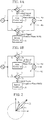
- FIGS. 1A and 1B is a configuration diagram showing a phase and amplitude controlled oscillation device according to a first embodiment.
- FIG. 1A is a configuration diagram showing the phase and amplitude controlled oscillation device of the first embodiment under a situation in which phase control is performed.
- FIG. 1B is a configuration diagram showing the phase and amplitude controlled oscillation device of the first embodiment under a situation in which amplitude control is performed.
- a reference oscillator 1 outputs a stable oscillation frequency f r .
- a first oscillator 2 is an inj ection-locked voltage-controlled oscillator (injection-locked oscillator) into which an output wave from the reference oscillator 1 is injected.
- an oscillation frequency f o1 is locked to the oscillation frequency f r of the reference oscillator 1.
- a second oscillator 3 is an injection-locked voltage-controlled oscillator into which an output wave from the reference oscillator 1 is injected.
- an oscillation frequency f o2 is locked to the oscillation frequency f r of the reference oscillator 1.
- first oscillator 2 and the second oscillator 3 are injection-locked voltage-controlled oscillators having the same configuration, and the characteristics of oscillation frequency with respect to direct-current control voltages provided to oscillation frequency control terminals 2a and 3a, etc., are the same.
- a combiner 4 combines an output wave from the first oscillator 2 and an output wave from the second oscillator 3 and outputs the combined output wave.
- the combiner 4 is, for example, a power combiner such as a Wilkinson combiner.
- a first controller 5 is connected to the oscillation frequency control terminal 2a of the first oscillator 2, and controls the phase of the oscillation frequency of the first oscillator 2 by outputting (applying) a control signal (direct-current voltage) that controls the oscillation frequency f o1 of the first oscillator 2 to the oscillation frequency control terminal 2a.
- a second controller 6 is connected to the oscillation frequency control terminal 3a of the second oscillator 3, and controls the phase of the oscillation frequency of the second oscillator 3 by outputting (applying) a control signal (direct-current voltage) that controls the oscillation frequency f o2 of the second oscillator 3 to the oscillation frequency control terminal 3a.
- the first controller 5 and the second controller 6 control the phase of the combined output wave obtained by the combiner 4 by performing control to shift the phase of the oscillation frequency of the first oscillator 2 and the phase of the oscillation frequency of the second oscillator 3 in the same direction.
- the first controller 5 and the second controller 6 control the amplitude of the combined output wave obtained by the combiner 4 by performing control to shift the phase of the oscillation frequency of the first oscillator 2 and the phase of the oscillation frequency of the second oscillator 3 in opposite directions.
- the reference oscillator 1 stably oscillates at the oscillation frequency f r , and outputs an output wave with the frequency f r as an injection wave to each of the first oscillator 2 and the second oscillator 3.
- the oscillation frequency f o1 of the first oscillator 2 is locked to the oscillation frequency f r of the reference oscillator 1.
- the oscillation frequency f o2 of the second oscillator 3 is locked to the oscillation frequency f r of the reference oscillator 1.
- phase of an output wave from the first oscillator 2 in which the oscillation frequency f o1 is locked to the oscillation frequency f r of the reference oscillator 1 is ⁇ r1
- phase of an output wave from the second oscillator 3 in which the oscillation frequency f o2 is locked to the oscillation frequency f r of the reference oscillator 1 is ⁇ r2 .
- the combiner 4 combines an output wave from the first oscillator 2 and an output wave from the second oscillator 3 and outputs the combined output wave.
- the combining of two output waves by the combiner 4 is vector synthesis.
- FIG. 2 is an explanatory diagram showing the phase of a combined output wave obtained by the combiner 4 at a time when the oscillation frequencies f o1 and f o2 are locked to the oscillation frequency f r .
- the reference sign 11 indicates the combined output wave obtained by the combiner 4.
- the first oscillator 2 oscillates at the oscillation frequency f o1 when an output wave with the frequency f r is not injected into the first oscillator 2 from the reference oscillator 1 and a control signal that changes the oscillation frequency f o1 by ⁇ f o is not provided to the oscillation frequency control terminal 2a.
- the oscillation frequency control terminal 2a When a control signal that changes the oscillation frequency f o1 by ⁇ f o is provided to the oscillation frequency control terminal 2a under a condition that an output wave with the frequency f r is not injected as an injection wave into the first oscillator 2, the oscillation frequency changes from f o1 to (f o1 + ⁇ f o ).
- the oscillation frequency control terminal 2a When a control signal that changes the oscillation frequency f o1 by ⁇ f o is provided to the oscillation frequency control terminal 2a under a condition that an output wave with the frequency f r is injected into the first oscillator 2 from the reference oscillator 1, the oscillation frequency is f r and the phase ⁇ r1 of an output wave is shifted by ⁇ i on the basis of a difference between the oscillation frequency f r and the frequency (f o1 + ⁇ f o ).
- the second oscillator 3 oscillates at the oscillation frequency f o2 when an output wave with the frequency f r is not injected into the second oscillator 3 from the reference oscillator 1 and a control signal that changes the oscillation frequency f o2 by ⁇ f o is not provided to the oscillation frequency control terminal 3a.
- the oscillation frequency control terminal 3a When a control signal that changes the oscillation frequency f o2 by ⁇ f o is provided to the oscillation frequency control terminal 3a under a condition that an output wave with the frequency f r is not injected into the second oscillator 3, the oscillation frequency changes from f o2 to (f o2 + ⁇ f o ).
- the combiner 4 combines an output wave from the first oscillator 2 and an output wave from the second oscillator 3 and outputs the combined output wave.
- FIG. 3 is an explanatory diagram showing the phase and amplitude of a combined output wave obtained by the combiner 4 at a time when a control signal that changes an oscillation frequency by ⁇ f o is provided to the oscillation frequency control terminals 2a and 3a.
- the reference sign 12 indicates a combined output wave obtained when an output wave with the frequency f r is injected into each of the first oscillator 2 and the second oscillator 3 and a control signal that changes an oscillation frequency by ⁇ f o is not provided to the oscillation frequency control terminals 2a and 3a.
- the reference sign 13 indicates a combined output wave obtained by the combiner 4 when an output wave with the frequency f r is injected into each of the first oscillator 2 and the second oscillator 3 and a control signal that changes an oscillation frequency by ⁇ f o is provided to the oscillation frequency control terminals 2a and 3a.
- the first controller 5 and the second controller 6 by performing control to shift the phase of the oscillation frequency of the first oscillator 2 and the phase of the oscillation frequency of the second oscillator 3 in the same direction, without changing the amplitude of a combined output wave obtained by the combiner 4, the phase can be changed.
- the oscillation frequency control terminal 3a When a control signal that changes the oscillation frequency f o2 by - ⁇ f o is provided to the oscillation frequency control terminal 3a under a condition that an output wave with the frequency f r is not injected into the second oscillator 3, the oscillation frequency changes from f o2 to (f o2 - ⁇ f o ).
- the combiner 4 combines an output wave from the first oscillator 2 and an output wave from the second oscillator 3 and outputs the combined output wave.
- FIG. 4 is an explanatory diagram showing the phase and amplitude of a combined output wave obtained by the combiner 4 at a time when a control signal that changes an oscillation frequency by ⁇ f o is provided to the oscillation frequency control terminal 2a and a control signal that changes an oscillation frequency by - ⁇ f o is provided to the oscillation frequency control terminal 3a.
- the reference sign 14 indicates a combined output wave obtained when an output wave with the frequency f r is injected into each of the first oscillator 2 and the second oscillator 3 and a control signal that changes an oscillation frequency is not provided to the oscillation frequency control terminals 2a and 3a.
- the reference sign 15 indicates a combined output wave obtained when an output wave with the frequency f r is injected into each of the first oscillator 2 and the second oscillator 3, a control signal that changes an oscillation frequency by ⁇ f o is provided to the oscillation frequency control terminal 2a, and a control signal that changes an oscillation frequency by - ⁇ f o is provided to the oscillation frequency control terminal 3a.
- the first controller 5 and the second controller 6 by performing control to shift the phase of an output wave from the first oscillator 2 and the phase of an output wave from the second oscillator 3 in opposite directions, without changing the phase of a combined output wave obtained by the combiner 4, the amplitude can be changed.
- both the phase and amplitude of a combined output wave obtained by the combiner 4 can be changed, thereby enabling phase and amplitude modulation.
- the combiner 4 can output a phase-modulated signal, an amplitude-modulated signal, or a phase and amplitude modulated signal as a combined output wave.
- the phase and amplitude controlled oscillation device is configured in such a manner that the first controller 5 and the second controller 6 control the phase of a combined output wave obtained by the combiner 4 by performing control to shift the phases of respective oscillation frequencies of the first oscillator 2 and the second oscillator 3 in the same direction, and control the amplitude of the combined output wave obtained by the combiner 4 by performing control to shift the phases of the respective oscillation frequencies of the first oscillator 2 and the second oscillator 3 in opposite directions. Therefore, the phase and amplitude controlled oscillation device can control the phase and amplitude of the combined output wave obtained by the combiner 4.
- injection-locked voltage-controlled oscillators are used as the first oscillator 2 and the second oscillator 3.
- injection-locked voltage-controlled oscillators are used as the first oscillator 2 and the second oscillator 3.
- a change in output power with respect to the power of an injection wave is small and the output power is roughly constant. Therefore, since the output power from the first oscillator 2 and the second oscillator 3 to the combiner 4 is roughly constant, fluctuations in the power of a combined output wave at a time when phase control is performed can be reduced, for example.
- an output wave from the reference oscillator 1 can be a subharmonic, that is, second or higher harmonic, of an output wave from each of the first oscillator 2 and the second oscillator 3 or may be a high-order harmonic.
- an output wave from the reference oscillator 1 By setting an output wave from the reference oscillator 1 to be, for example, a subharmonic, the output wave can be transmitted with low loss.
- injection-locked voltage-controlled oscillators are used as the first oscillator 2 and the second oscillator 3.
- injection-locked current-controlled oscillators injection-locked oscillators
- a control signal outputted from each of the first controller 5 and the second controller 6 is a voltage signal.
- a control signal outputted from each of the first controller 5 and the second controller 6 is a current signal.
- an output wave from the reference oscillator 1 is injected into each of the first oscillator 2 and the second oscillator 3.
- a second embodiment describes a phase and amplitude controlled oscillation device in which an output wave from the reference oscillator 1 is injected into the first oscillator 2 and a part of an output wave from the first oscillator 2 is injected into a second oscillator 8.
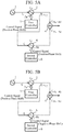
- FIGS. 5A and 5B is a configuration diagram showing a phase and amplitude controlled oscillation device according to the second embodiment.
- FIG. 5A is a configuration diagram showing the phase and amplitude controlled oscillation device of the second embodiment under a situation in which phase control is performed.
- FIG. 5B is a configuration diagram showing the phase and amplitude controlled oscillation device of the second embodiment under a situation in which amplitude control is performed.
- FIGS. 5A and 5B the same reference signs as those of FIG. 1A and 1B indicate the same or corresponding portions and thus description thereof is omitted.
- a splitter 7 splits an output wave from the first oscillator 2, and outputs one split output wave to the combiner 4 and outputs the other split output wave to the second oscillator 8.
- the second oscillator 8 is an injection-locked voltage-controlled oscillator into which the other output wave outputted from the splitter 7 is injected.
- the oscillation frequency f o2 is locked to the oscillation frequency f o1 of the first oscillator 2.
- phase and amplitude controlled oscillation device shown in FIGS. 5A and 5B differs from the phase and amplitude controlled oscillation device shown in FIGS. 1A and 1B only in that the phase and amplitude controlled oscillation device includes the splitter 7 and the other output wave outputted from the splitter 7 is injected into the second oscillator 8.
- the oscillation frequency f o2 is locked to the oscillation frequency f o1 of the first oscillator 2.
- the oscillation frequency f o1 is locked to the oscillation frequency f r of the reference oscillator 1 by injection of an output wave with the frequency f r into the first oscillator 2 from the reference oscillator 1, the oscillation frequency f o2 of the second oscillator 8 also turns out to be locked to the oscillation frequency f r of the reference oscillator 1.
- the phase and amplitude controlled oscillation device shown in FIGS. 5A and 5B can control the phase and amplitude of a combined output wave obtained by the combiner 4.
- a third embodiment describes a phase and amplitude controlled oscillation device in which a first oscillator 21 is a first phase-locked oscillator of a fractional-N system and a second oscillator 31 is a second phase-locked oscillator of a fractional-N system.
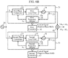
- FIGS. 6A and 6B is a configuration diagram showing a phase and amplitude controlled oscillation device according to the third embodiment.
- FIG. 6A is a configuration diagram showing the phase and amplitude controlled oscillation device of the third embodiment under a situation in which phase control is performed.
- FIG. 6B is a configuration diagram showing the phase and amplitude controlled oscillation device of the third embodiment under a situation in which amplitude control is performed.
- a reference oscillator 20 is a crystal oscillator that outputs an output wave with the frequency f r and the phase ⁇ r to each of the first oscillator 21 and the second oscillator 31.
- the first oscillator 21 includes a first phase comparator 22, a first loop filter 23, a first voltage-controlled oscillator 24, a first splitter 25, and a first frequency divider 26.
- the first oscillator 21 is a first phase-locked oscillator of a fractional-N system and includes a phase-locked loop (PLL).
- PLL phase-locked loop
- An output wave from the first voltage-controlled oscillator 24 is split by the first splitter 25, and one split output wave is outputted to a combiner 40 as an output wave from the first oscillator 21.
- the other split output wave is outputted to the first frequency divider 26.
- the oscillation frequency f o1 changes so as to reduce a phase error between the phase of the other split output wave (an output wave from the first voltage-controlled oscillator 24) whose frequency is divided by the first frequency divider 26 and the phase of an output wave from the reference oscillator 20.
- the first phase comparator 22 outputs a voltage based on the phase error between the phase ⁇ r of the output wave from the reference oscillator 20 and the phase ⁇ r1 of the output wave from the first frequency divider 26, to the first loop filter 23.
- the first loop filter 23 allows only components near a direct-current component of the voltage outputted from the first phase comparator 22 to pass therethrough and outputs the components near the direct-current component to an oscillation frequency control terminal 24a of the first voltage-controlled oscillator 24.
- the first voltage-controlled oscillator 24 is an oscillator in which when a voltage (control voltage) outputted from the first loop filter 23 is provided to the oscillation frequency control terminal 24a, the oscillation frequency f o1 changes on the basis of the control voltage as shown in FIG. 7 .
- FIG. 7 is an explanatory diagram showing, as an example, a relationship between a control voltage and an oscillation frequency at each of the oscillation frequency control terminal 24a of the first voltage-controlled oscillator 24 and an oscillation frequency control terminal 34a of a second voltage-controlled oscillator 34.
- the second oscillator 31 includes a second phase comparator 32, a second loop filter 33, the second voltage-controlled oscillator 34, a second splitter 35, and a second frequency divider 36.
- the second oscillator 31 is a second phase-locked oscillator of a fractional-N system and includes a PLL.
- An output wave from the second voltage-controlled oscillator 34 is split by the second splitter 35, and one split output wave is outputted to the combiner 40 as an output wave from the second oscillator 31.
- the other split output wave is outputted to the second frequency divider 36.
- the oscillation frequency f o2 changes so as to reduce a phase error between the phase of the other split output wave (an output wave from the second voltage-controlled oscillator 34) whose frequency is divided by the second frequency divider 36 and the phase of an output wave from the reference oscillator 20.
- the second phase comparator 32 outputs a voltage based on the phase error between the phase ⁇ r of the output wave from the reference oscillator 20 and the phase ⁇ r2 of the output wave from the second frequency divider 36, to the second loop filter 33.
- the second loop filter 33 allows only components near a direct-current component of the voltage outputted from the second phase comparator 32 to pass therethrough and outputs the components near the direct-current component to the oscillation frequency control terminal 34a of the second voltage-controlled oscillator 34.
- the second voltage-controlled oscillator 34 is an oscillator in which when a voltage (control voltage) outputted from the second loop filter 33 is provided to the oscillation frequency control terminal 34a, the oscillation frequency f o2 changes as shown in FIG. 7 .
- the combiner 40 combines one split output wave obtained by the first splitter 25 and the other split output wave obtained by the second splitter 35 and outputs the combined output wave.
- the combiner 40 is, for example, a power combiner such as a Wilkinson combiner.
- a first controller 41 can control the oscillation frequency of the first voltage-controlled oscillator 24 by controlling the frequency division number of the first frequency divider 26, and can control the phase of an output wave from the first voltage-controlled oscillator 24 by changing a control pattern of a frequency division number.
- a second controller 42 can control the oscillation frequency of the second voltage-controlled oscillator 34 by controlling the frequency division number of the second frequency divider 36, and can control the phase of an output wave from the second voltage-controlled oscillator 34 by changing a control pattern of a frequency division number.
- the reference oscillator 20 outputs an output wave with the frequency f r and the phase ⁇ r to each of the first oscillator 21 and the second oscillator 31.
- the first splitter 25 splits an output wave from the first voltage-controlled oscillator 24, and outputs one split output wave to the combiner 40 and outputs the other split output wave to the first frequency divider 26.
- the first frequency divider 26 When the first frequency divider 26 receives the other split output wave from the first splitter 25, the first frequency divider 26 divides the frequency of the output wave by N (N is an integer greater than or equal to 2) and outputs an output wave with the frequency f o1 /N and the phase ⁇ r1 to the first phase comparator 22.
- the first phase comparator 22 compares the phase ⁇ r of the output wave from the reference oscillator 20 with the phase ⁇ r1 of the output wave from the first frequency divider 26, and outputs a voltage (or a current) based on a phase error ( ⁇ r - ⁇ r1 ) between the phase ⁇ r and the phase ⁇ r1 to the first loop filter 23.
- the first loop filter 23 When the first loop filter 23 receives the voltage (or current) based on the phase error ( ⁇ r - ⁇ r1 ) from the first phase comparator 22, the first loop filter 23 allows only components near a direct-current component of the voltage (or current) to pass therethrough and outputs the components near the direct-current component as a control voltage to the oscillation frequency control terminal 24a of the first voltage-controlled oscillator 24.
- the oscillation frequency f o1 changes on the basis of the control voltage as shown in FIG. 7 .
- the second splitter 35 splits an output wave from the second voltage-controlled oscillator 34, and outputs one split output wave to the combiner 40 and outputs the other split output wave to the second frequency divider 36.
- the second frequency divider 36 When the second frequency divider 36 receives the other split output wave from the second splitter 35, the second frequency divider 36 divides the frequency of the output wave by N and outputs an output wave with the frequency f o2 /N and the phase ⁇ r2 to the second phase comparator 32.
- the second phase comparator 32 compares the phase ⁇ r of the output wave from the reference oscillator 20 with the phase ⁇ r2 of the output wave from the second frequency divider 36, and outputs a voltage (or a current) based on a phase error ( ⁇ r - ⁇ r2 ) between the phase ⁇ r and the phase ⁇ r2 to the second loop filter 33.
- the second loop filter 33 When the second loop filter 33 receives the voltage (or current) based on the phase error ( ⁇ r - ⁇ r2 ) from the second phase comparator 32, the second loop filter 33 allows only components near a direct-current component of the voltage (or current) to pass therethrough and outputs the components near the direct-current component as a control voltage to the oscillation frequency control terminal 34a of the second voltage-controlled oscillator 34.
- the oscillation frequency f o2 changes on the basis of the control voltage as shown in FIG. 7 .
- the first controller 41 controls the frequency division number N of the first frequency divider 26.
- the frequency division number N is given by an average value Nave in a given period.
- the oscillation frequency is constant.
- the phase can be changed with the oscillation frequency remaining constant.
- the control pattern of a frequency division number is a pattern that is offset along a time axis, and thus, the oscillation frequency does not change but the phase changes.
- the second controller 42 controls the frequency division number N of the second frequency divider 36.
- the oscillation frequency is constant.
- the phase can be changed with the oscillation frequency remaining constant.
- the first controller 41 performs control of a first control pattern in which the timing of a control pattern of a frequency division number is shifted with the average value of a frequency division number in a given period of the first frequency divider 26 remaining constant.
- the first controller 41 controls timing at which the first control pattern is offset or timing at which the first control pattern is reset, with the average value of a frequency division number remaining constant.
- the second controller 42 performs control of a second control pattern in which the timing of a control pattern of a frequency division number is shifted with the average value of a frequency division number in a given period of the second frequency divider 36 remaining constant.
- the second controller 42 controls timing at which the second control pattern is offset or timing at which the second control pattern is reset, with the average value of a frequency division number remaining constant.
- the first controller 41 for example, advancing timing at which the first control pattern is outputted to the first frequency divider 26 by ⁇ t, the phase of an output wave from the first voltage-controlled oscillator 24 can be shifted by ⁇ 0 .
- the first controller 41 for example, delaying timing at which the first control pattern is outputted to the first frequency divider 26 by ⁇ t, the phase of an output wave from the first voltage-controlled oscillator 24 can be shifted by - ⁇ 0 .
- the second controller 42 for example, advancing timing at which the second control pattern is outputted to the second frequency divider 36 by ⁇ t, the phase of an output wave from the second voltage-controlled oscillator 34 can be shifted by ⁇ 0 .
- the second controller 42 for example, delaying timing at which the second control pattern is outputted to the second frequency divider 36 by ⁇ t, the phase of an output wave from the second voltage-controlled oscillator 34 can be shifted by - ⁇ 0 .
- the combiner 40 When the combiner 40 combines a split output wave obtained by the first splitter 25 and a split output wave obtained by the second splitter 35 when the first controller 41 shifts the phase by ⁇ 0 and the second controller 42 shifts the phase by ⁇ 0 , the amplitude of the combined output wave does not change, but the phase is shifted by ⁇ 0 . By continuously performing this process, phase modulation can be performed.
- the combiner 40 When the combiner 40 combines a split output wave obtained by the first splitter 25 and a split output wave obtained by the second splitter 35 when the first controller 41 shifts the phase by ⁇ 0 and the second controller 42 shifts the phase by - ⁇ 0 , the phase of the combined output wave does not change, but the amplitude changes. By continuously performing this process, amplitude modulation can be performed.
- both the phase and amplitude of a combined output wave obtained by the combiner 40 can be changed, thereby enabling phase and amplitude modulation.
- the combiner 40 can output a phase-modulated signal, an amplitude-modulated signal, or a phase and amplitude modulated signal as a combined output wave.
- the phase and amplitude controlled oscillation device is configured in such a manner that the first controller 41 controls the phase of an output wave from the first phase-locked oscillator by controlling the frequency division number of the first phase-locked oscillator, and the second controller 42 controls the phase of an output wave from the second phase-locked oscillator by controlling the frequency division number of the second phase-locked oscillator. Therefore, the phase and amplitude controlled oscillation device can control the phase and amplitude of a combined output wave obtained by the combiner 40.
- phase-locked oscillators of a fractional-N system are used as the first oscillator 21 and the second oscillator 31.
- phase-locked oscillators of a fractional-N system are used as the first oscillator 21 and the second oscillator 31, not only the phase and amplitude of a combined output wave obtained by the combiner 40, but also the frequency of the combined output wave can be controlled.
- each of the first controller 41 and the second controller 42 can be composed of a digital circuit.
- an output wave from the reference oscillator 20 is outputted to each of the first phase comparator 22 and the second phase comparator 32.
- a fourth embodiment describes a phase and amplitude controlled oscillation device in which an output wave from the reference oscillator 20 is outputted to the first phase comparator 22 and an output wave from the first frequency divider 26 is outputted to a second phase comparator 37.
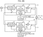
- FIGS. 8A and 8B is a configuration diagram showing a phase and amplitude controlled oscillation device according to the fourth embodiment.
- FIG. 8A is a configuration diagram showing the phase and amplitude controlled oscillation device of the fourth embodiment under a situation in which phase control is performed.
- FIG. 8B is a configuration diagram showing the phase and amplitude controlled oscillation device of the fourth embodiment under a situation in which amplitude control is performed.
- FIGS. 8A and 8B the same reference signs as those of FIGS. 1 and 6 indicate the same or corresponding portions and thus description thereof is omitted.
- the second oscillator 31 includes the second phase comparator 37, the second loop filter 33, the second voltage-controlled oscillator 34, the second splitter 35, and the second frequency divider 36.
- the second phase comparator 37 outputs a voltage based on a phase error between the phase ⁇ r1 of an output wave from the first frequency divider 26 and the phase ⁇ r2 of an output wave from the second frequency divider 36, to the second loop filter 33.
- the phase and amplitude controlled oscillation device shown in FIGS. 8A and 8B differs from the phase and amplitude controlled oscillation device shown in FIGS. 6A and 6B only in that the second oscillator 31 includes the second phase comparator 37 instead of the second phase comparator 32.
- the second oscillator 31 includes the second phase comparator 37
- the phase and amplitude controlled oscillation device shown in FIGS. 8A and 8B can control the phase and amplitude of a combined output wave obtained by the combiner 40.
- the invention is suitable for a phase and amplitude controlled oscillation device that controls the phase and amplitude of an output wave.
- 1 reference oscillator, 2: first oscillator, 2a: oscillation frequency control terminal, 3: second oscillator, 3a: oscillation frequency control terminal, 4: combiner, 5: first controller, 6: second controller, 7: splitter, 8: second oscillator, 8a: oscillation frequency control terminal, 11 to 15: combined output wave, 20: reference oscillator, 21: first oscillator, 22: first phase comparator, 23: first loop filter, 24: first voltage-controlled oscillator, 24a: oscillation frequency control terminal, 25: first splitter, 26: first frequency divider, 31: second oscillator, 32, 37: second phase comparator, 33: second loop filter, 34: second voltage-controlled oscillator, 34a: oscillation frequency control terminal, 35: second splitter, 36: second frequency divider, 40: combiner, 41: first controller, 42: second controller
Landscapes
- Physics & Mathematics (AREA)
- Nonlinear Science (AREA)
- Stabilization Of Oscillater, Synchronisation, Frequency Synthesizers (AREA)
Abstract
Description
- The invention relates to a phase and amplitude controlled oscillation device that controls the phase and amplitude of a combined output wave.
- The following Patent Literature 1 discloses a phase-locked loop frequency synthesizer of a fractional-N system.
- The phase-locked loop frequency synthesizer disclosed in Patent Literature 1 controls the phase of an output signal by giving an offset to a control pattern of a frequency divider that is locked to a reference signal.
- Patent Literature 1:
WO 2007/091516 A - The phase-locked loop frequency synthesizer disclosed in Patent Literature 1 can control the phase of an output signal.
- However, the phase-locked loop frequency synthesizer disclosed in Patent Literature 1 has a problem that the amplitude of the output signal cannot be controlled.
- The invention is made to solve the above problem, and an object of the invention is to obtain a phase and amplitude controlled oscillation device that can control the phase and amplitude of a combined output wave.
- A phase and amplitude controlled oscillation device according to the invention includes: a reference oscillator outputting an oscillation frequency; a first oscillator whose oscillation frequency is locked to the oscillation frequency of the reference oscillator; a second oscillator whose oscillation frequency is locked to the oscillation frequency of the reference oscillator; a combiner generating a combined output wave by combining an output wave from the first oscillator and an output wave from the second oscillator; a first controller controlling a phase of the oscillation frequency of the first oscillator; and a second controller controlling a phase of the oscillation frequency of the second oscillator. The first and second controllers control a phase of the combined output wave generated by the combiner by performing control to shift the phases of the oscillation frequencies of the respective first and second oscillators in a same direction, and control an amplitude of the combined output wave generated by the combiner by performing control to shift the phases of the oscillation frequencies of the respective first and second oscillators in opposite directions.
- According to the invention, the phase and amplitude controlled oscillation device is configured in such a manner that the first and second controllers control a phase of the combined output wave generated by the combiner by performing control to shift the phases of the oscillation frequencies of the respective first and second oscillators in a same direction, and control an amplitude of the combined output wave generated by the combiner by performing control to shift the phases of the oscillation frequencies of the respective first and second oscillators in opposite directions. Therefore, the phase and amplitude controlled oscillation device according to the invention can control the phase and amplitude of the combined output wave.
-
-
FIG. 1A is a configuration diagram showing a phase and amplitude controlled oscillation device of a first embodiment under a situation in which phase control is performed, andFIG. 1B is a configuration diagram showing the phase and amplitude controlled oscillation device of the first embodiment under a situation in which amplitude control is performed. -
FIG. 2 is an explanatory diagram showing the phase of a combined output wave obtained by acombiner 4 at a time when oscillation frequencies fo1 and fo2 are locked to an oscillation frequency fr. -
FIG. 3 is an explanatory diagram showing the phase and amplitude of a combined output wave obtained by thecombiner 4 at a time when a control signal that changes an oscillation frequency by Δfo is provided to oscillationfrequency control terminals -
FIG. 4 is an explanatory diagram showing the phase and amplitude of a combined output wave obtained by thecombiner 4 at a time when a control signal that changes an oscillation frequency by Δfo is provided to the oscillationfrequency control terminal 2a and a control signal that changes an oscillation frequency by -Δfo is provided to the oscillationfrequency control terminal 3a. -
FIG. 5A is a configuration diagram showing a phase and amplitude controlled oscillation device of a second embodiment under a situation in which phase control is performed, andFIG. 5B is a configuration diagram showing the phase and amplitude controlled oscillation device of the second embodiment under a situation in which amplitude control is performed. -
FIG. 6A is a configuration diagram showing a phase and amplitude controlled oscillation device of a third embodiment under a situation in which phase control is performed, andFIG. 6B is a configuration diagram showing the phase and amplitude controlled oscillation device of the third embodiment under a situation in which amplitude control is performed. -
FIG. 7 is an explanatory diagram showing a relationship between a control voltage at each of an oscillationfrequency control terminal 24a of a first voltage-controlledoscillator 24 and an oscillationfrequency control terminal 34a of a second voltage-controlledoscillator 34 and an oscillation frequency. - Each of
FIGS. 8A and8B is a configuration diagram showing a phase and amplitude controlled oscillation device of a fourth embodiment under a situation in which phase control is performed, andFIG. 8B is a configuration diagram showing the phase and amplitude controlled oscillation device of the fourth embodiment under a situation in which amplitude control is performed. - To describe the invention in more detail, some embodiments for carrying out the invention will be described below with reference to the accompanying drawings.
- Each of
FIGS. 1A and 1B is a configuration diagram showing a phase and amplitude controlled oscillation device according to a first embodiment. -
FIG. 1A is a configuration diagram showing the phase and amplitude controlled oscillation device of the first embodiment under a situation in which phase control is performed. -
FIG. 1B is a configuration diagram showing the phase and amplitude controlled oscillation device of the first embodiment under a situation in which amplitude control is performed. - In
FIGS. 1A and 1B , a reference oscillator 1 outputs a stable oscillation frequency fr. - A
first oscillator 2 is an inj ection-locked voltage-controlled oscillator (injection-locked oscillator) into which an output wave from the reference oscillator 1 is injected. - By the injection of the output wave from the reference oscillator 1 into the
first oscillator 2, an oscillation frequency fo1 is locked to the oscillation frequency fr of the reference oscillator 1. - A
second oscillator 3 is an injection-locked voltage-controlled oscillator into which an output wave from the reference oscillator 1 is injected. - By the injection of the output wave from the reference oscillator 1 into the
second oscillator 3, an oscillation frequency fo2 is locked to the oscillation frequency fr of the reference oscillator 1. - Note that the
first oscillator 2 and thesecond oscillator 3 are injection-locked voltage-controlled oscillators having the same configuration, and the characteristics of oscillation frequency with respect to direct-current control voltages provided to oscillationfrequency control terminals - A
combiner 4 combines an output wave from thefirst oscillator 2 and an output wave from thesecond oscillator 3 and outputs the combined output wave. Thecombiner 4 is, for example, a power combiner such as a Wilkinson combiner. - A
first controller 5 is connected to the oscillationfrequency control terminal 2a of thefirst oscillator 2, and controls the phase of the oscillation frequency of thefirst oscillator 2 by outputting (applying) a control signal (direct-current voltage) that controls the oscillation frequency fo1 of thefirst oscillator 2 to the oscillationfrequency control terminal 2a. - A
second controller 6 is connected to the oscillationfrequency control terminal 3a of thesecond oscillator 3, and controls the phase of the oscillation frequency of thesecond oscillator 3 by outputting (applying) a control signal (direct-current voltage) that controls the oscillation frequency fo2 of thesecond oscillator 3 to the oscillationfrequency control terminal 3a. - The
first controller 5 and thesecond controller 6 control the phase of the combined output wave obtained by thecombiner 4 by performing control to shift the phase of the oscillation frequency of thefirst oscillator 2 and the phase of the oscillation frequency of thesecond oscillator 3 in the same direction. - The
first controller 5 and thesecond controller 6 control the amplitude of the combined output wave obtained by thecombiner 4 by performing control to shift the phase of the oscillation frequency of thefirst oscillator 2 and the phase of the oscillation frequency of thesecond oscillator 3 in opposite directions. - Next, operation of the phase and amplitude controlled oscillation device shown in
FIG. 1 will be described. - The reference oscillator 1 stably oscillates at the oscillation frequency fr, and outputs an output wave with the frequency fr as an injection wave to each of the
first oscillator 2 and thesecond oscillator 3. - By the injection of the output wave with the frequency fr into the
first oscillator 2 from the reference oscillator 1, the oscillation frequency fo1 of thefirst oscillator 2 is locked to the oscillation frequency fr of the reference oscillator 1. - By the injection of the output wave with the frequency fr into the
second oscillator 3 from the reference oscillator 1, the oscillation frequency fo2 of thesecond oscillator 3 is locked to the oscillation frequency fr of the reference oscillator 1. - By the locking of the oscillation frequency fo1 of the
first oscillator 2 and the oscillation frequency fo2 of thesecond oscillator 3 to the oscillation frequency fr of the reference oscillator 1, the relation fo1 = fo2 = fr is satisfied. - Here, it is assumed that the phase of an output wave from the
first oscillator 2 in which the oscillation frequency fo1 is locked to the oscillation frequency fr of the reference oscillator 1 is θr1, and the phase of an output wave from thesecond oscillator 3 in which the oscillation frequency fo2 is locked to the oscillation frequency fr of the reference oscillator 1 is θr2. - As shown in
FIGS. 2A and 2B , thecombiner 4 combines an output wave from thefirst oscillator 2 and an output wave from thesecond oscillator 3 and outputs the combined output wave. The combining of two output waves by thecombiner 4 is vector synthesis. -
FIG. 2 is an explanatory diagram showing the phase of a combined output wave obtained by thecombiner 4 at a time when the oscillation frequencies fo1 and fo2 are locked to the oscillation frequency fr. - In
FIG. 2 , thereference sign 11 indicates the combined output wave obtained by thecombiner 4. - The
first oscillator 2 oscillates at the oscillation frequency fo1 when an output wave with the frequency fr is not injected into thefirst oscillator 2 from the reference oscillator 1 and a control signal that changes the oscillation frequency fo1 by Δfo is not provided to the oscillationfrequency control terminal 2a. - When a control signal that changes the oscillation frequency fo1 by Δfo is provided to the oscillation
frequency control terminal 2a under a condition that an output wave with the frequency fr is not injected as an injection wave into thefirst oscillator 2, the oscillation frequency changes from fo1 to (fo1+Δfo). - When a control signal that changes the oscillation frequency fo1 by Δfo is provided to the oscillation
frequency control terminal 2a under a condition that an output wave with the frequency fr is injected into thefirst oscillator 2 from the reference oscillator 1, the oscillation frequency is fr and the phase θr1 of an output wave is shifted by Δθi on the basis of a difference between the oscillation frequency fr and the frequency (fo1+Δfo). - The
second oscillator 3 oscillates at the oscillation frequency fo2 when an output wave with the frequency fr is not injected into thesecond oscillator 3 from the reference oscillator 1 and a control signal that changes the oscillation frequency fo2 by Δfo is not provided to the oscillationfrequency control terminal 3a. - When a control signal that changes the oscillation frequency fo2 by Δfo is provided to the oscillation
frequency control terminal 3a under a condition that an output wave with the frequency fr is not injected into thesecond oscillator 3, the oscillation frequency changes from fo2 to (fo2+Δfo). - When a control signal that changes the oscillation frequency fo2 by Δfo is provided to the oscillation
frequency control terminal 3a under a condition that an output wave with the frequency fr is injected into thesecond oscillator 3 from the reference oscillator 1, the oscillation frequency is fr and the phase θr2 of an output wave is shifted by Δθ2 on the basis of a difference between the oscillation frequency fr and the frequency (fo2+Δfo). - Here, the
first oscillator 2 and thesecond oscillator 3 are injection-locked voltage-controlled oscillators having the same configuration, and the characteristics of oscillation frequency with respect to control voltages provided to the oscillationfrequency control terminals - As shown in
FIG. 3 , thecombiner 4 combines an output wave from thefirst oscillator 2 and an output wave from thesecond oscillator 3 and outputs the combined output wave. -
FIG. 3 is an explanatory diagram showing the phase and amplitude of a combined output wave obtained by thecombiner 4 at a time when a control signal that changes an oscillation frequency by Δfo is provided to the oscillationfrequency control terminals - In
FIG. 3 , thereference sign 12 indicates a combined output wave obtained when an output wave with the frequency fr is injected into each of thefirst oscillator 2 and thesecond oscillator 3 and a control signal that changes an oscillation frequency by Δfo is not provided to the oscillationfrequency control terminals - The
reference sign 13 indicates a combined output wave obtained by thecombiner 4 when an output wave with the frequency fr is injected into each of thefirst oscillator 2 and thesecond oscillator 3 and a control signal that changes an oscillation frequency by Δfo is provided to the oscillationfrequency control terminals - When the combined
output wave 12 is compared with the combinedoutput wave 13, their amplitudes are the same but their phases are different from each other. - Therefore, by the
first controller 5 and thesecond controller 6, by performing control to shift the phase of the oscillation frequency of thefirst oscillator 2 and the phase of the oscillation frequency of thesecond oscillator 3 in the same direction, without changing the amplitude of a combined output wave obtained by thecombiner 4, the phase can be changed. - When a control signal that changes the oscillation frequency fo2 by -Δfo is provided to the oscillation
frequency control terminal 3a under a condition that an output wave with the frequency fr is not injected into thesecond oscillator 3, the oscillation frequency changes from fo2 to (fo2-Δfo). - When a control signal that changes the oscillation frequency fo2 by -Δfo is provided to the oscillation
frequency control terminal 3a under a condition that an output wave with the frequency fr is injected into thesecond oscillator 3 from the reference oscillator 1, the oscillation frequency is fr and the phase θr2 of an output wave is shifted by -Δθ2 on the basis of a difference between the oscillation frequency fr and the frequency (fo2-Δfo). - Here, the
first oscillator 2 and thesecond oscillator 3 are injection-locked voltage-controlled oscillators having the same configuration, and the characteristics of oscillation frequency with respect to control voltages provided to the oscillationfrequency control terminals - As shown in
FIG. 4 , thecombiner 4 combines an output wave from thefirst oscillator 2 and an output wave from thesecond oscillator 3 and outputs the combined output wave. -
FIG. 4 is an explanatory diagram showing the phase and amplitude of a combined output wave obtained by thecombiner 4 at a time when a control signal that changes an oscillation frequency by Δfo is provided to the oscillationfrequency control terminal 2a and a control signal that changes an oscillation frequency by -Δfo is provided to the oscillationfrequency control terminal 3a. - In
FIG. 4 , thereference sign 14 indicates a combined output wave obtained when an output wave with the frequency fr is injected into each of thefirst oscillator 2 and thesecond oscillator 3 and a control signal that changes an oscillation frequency is not provided to the oscillationfrequency control terminals - The
reference sign 15 indicates a combined output wave obtained when an output wave with the frequency fr is injected into each of thefirst oscillator 2 and thesecond oscillator 3, a control signal that changes an oscillation frequency by Δfo is provided to the oscillationfrequency control terminal 2a, and a control signal that changes an oscillation frequency by -Δfo is provided to the oscillationfrequency control terminal 3a. - When the combined
output wave 14 is compared with the combinedoutput wave 15, their phases are the same but their amplitudes are different from each other. - Therefore, by the
first controller 5 and thesecond controller 6, by performing control to shift the phase of an output wave from thefirst oscillator 2 and the phase of an output wave from thesecond oscillator 3 in opposite directions, without changing the phase of a combined output wave obtained by thecombiner 4, the amplitude can be changed. - Note that by combining the above-described configurations, both the phase and amplitude of a combined output wave obtained by the
combiner 4 can be changed, thereby enabling phase and amplitude modulation. - Therefore, the
combiner 4 can output a phase-modulated signal, an amplitude-modulated signal, or a phase and amplitude modulated signal as a combined output wave. - In the above-described first embodiment, the phase and amplitude controlled oscillation device is configured in such a manner that the
first controller 5 and thesecond controller 6 control the phase of a combined output wave obtained by thecombiner 4 by performing control to shift the phases of respective oscillation frequencies of thefirst oscillator 2 and thesecond oscillator 3 in the same direction, and control the amplitude of the combined output wave obtained by thecombiner 4 by performing control to shift the phases of the respective oscillation frequencies of thefirst oscillator 2 and thesecond oscillator 3 in opposite directions. Therefore, the phase and amplitude controlled oscillation device can control the phase and amplitude of the combined output wave obtained by thecombiner 4. - In the phase and amplitude controlled oscillation device of the first embodiment, injection-locked voltage-controlled oscillators are used as the
first oscillator 2 and thesecond oscillator 3. When injection-locked voltage-controlled oscillators are used as thefirst oscillator 2 and thesecond oscillator 3, a change in output power with respect to the power of an injection wave is small and the output power is roughly constant. Therefore, since the output power from thefirst oscillator 2 and thesecond oscillator 3 to thecombiner 4 is roughly constant, fluctuations in the power of a combined output wave at a time when phase control is performed can be reduced, for example. - In addition, when injection-locked voltage-controlled oscillators are used as the
first oscillator 2 and thesecond oscillator 3, the oscillation frequency fr of the reference oscillator 1 can be one-half, one-third, twice, three times, etc., the oscillation frequency fo1 (≈ fo2). Therefore, an output wave from the reference oscillator 1 can be a subharmonic, that is, second or higher harmonic, of an output wave from each of thefirst oscillator 2 and thesecond oscillator 3 or may be a high-order harmonic. - By setting an output wave from the reference oscillator 1 to be, for example, a subharmonic, the output wave can be transmitted with low loss.
- In the phase and amplitude controlled oscillation device of the first embodiment, injection-locked voltage-controlled oscillators are used as the
first oscillator 2 and thesecond oscillator 3. However, this is merely an example and, for example, injection-locked current-controlled oscillators (injection-locked oscillators) may be used as thefirst oscillator 2 and thesecond oscillator 3. - Note that when the
first oscillator 2 and thesecond oscillator 3 are injection-locked voltage-controlled oscillators, a control signal outputted from each of thefirst controller 5 and thesecond controller 6 is a voltage signal. - When the
first oscillator 2 and thesecond oscillator 3 are injection-locked current-controlled oscillators, a control signal outputted from each of thefirst controller 5 and thesecond controller 6 is a current signal. - In the phase and amplitude controlled oscillation device of the first embodiment, an output wave from the reference oscillator 1 is injected into each of the
first oscillator 2 and thesecond oscillator 3. - A second embodiment describes a phase and amplitude controlled oscillation device in which an output wave from the reference oscillator 1 is injected into the
first oscillator 2 and a part of an output wave from thefirst oscillator 2 is injected into asecond oscillator 8. - Each of
FIGS. 5A and 5B is a configuration diagram showing a phase and amplitude controlled oscillation device according to the second embodiment. -
FIG. 5A is a configuration diagram showing the phase and amplitude controlled oscillation device of the second embodiment under a situation in which phase control is performed. -
FIG. 5B is a configuration diagram showing the phase and amplitude controlled oscillation device of the second embodiment under a situation in which amplitude control is performed. - In
FIGS. 5A and 5B , the same reference signs as those ofFIG. 1A and 1B indicate the same or corresponding portions and thus description thereof is omitted. - A splitter 7 splits an output wave from the
first oscillator 2, and outputs one split output wave to thecombiner 4 and outputs the other split output wave to thesecond oscillator 8. - The
second oscillator 8 is an injection-locked voltage-controlled oscillator into which the other output wave outputted from the splitter 7 is injected. - By the injection of the other output wave outputted from the splitter 7 into the
second oscillator 8, the oscillation frequency fo2 is locked to the oscillation frequency fo1 of thefirst oscillator 2. - When a control signal is provided from the
second controller 6 to an oscillationfrequency control terminal 8a, as with thesecond oscillator 3 shown inFIGS. 1A and 1B , the oscillation frequency fo2 of thesecond oscillator 8 changes. - Next, operation of the phase and amplitude controlled oscillation device shown in
FIGS. 5A and 5B will be described. - The phase and amplitude controlled oscillation device shown in
FIGS. 5A and 5B differs from the phase and amplitude controlled oscillation device shown inFIGS. 1A and 1B only in that the phase and amplitude controlled oscillation device includes the splitter 7 and the other output wave outputted from the splitter 7 is injected into thesecond oscillator 8. - By the injection of the other output wave outputted from the splitter 7 into the
second oscillator 8, the oscillation frequency fo2 is locked to the oscillation frequency fo1 of thefirst oscillator 2. - Since the oscillation frequency fo1 is locked to the oscillation frequency fr of the reference oscillator 1 by injection of an output wave with the frequency fr into the
first oscillator 2 from the reference oscillator 1, the oscillation frequency fo2 of thesecond oscillator 8 also turns out to be locked to the oscillation frequency fr of the reference oscillator 1. - Therefore, in the phase and amplitude controlled oscillation device shown in
FIG. 5A and 5B , too, as with the phase and amplitude controlled oscillation device shown inFIGS. 1A and 1B , the relation fo1 = fo2 = fr is satisfied. - Since control by the
first controller 5 and thesecond controller 6 itself is the same as that of the first embodiment, as with the phase and amplitude controlled oscillation device shown inFIGS. 1A and 1B , the phase and amplitude controlled oscillation device shown inFIGS. 5A and 5B can control the phase and amplitude of a combined output wave obtained by thecombiner 4. - A third embodiment describes a phase and amplitude controlled oscillation device in which a
first oscillator 21 is a first phase-locked oscillator of a fractional-N system and asecond oscillator 31 is a second phase-locked oscillator of a fractional-N system. - Each of
FIGS. 6A and6B is a configuration diagram showing a phase and amplitude controlled oscillation device according to the third embodiment. -
FIG. 6A is a configuration diagram showing the phase and amplitude controlled oscillation device of the third embodiment under a situation in which phase control is performed. -
FIG. 6B is a configuration diagram showing the phase and amplitude controlled oscillation device of the third embodiment under a situation in which amplitude control is performed. - In
FIGS. 6A and6B , areference oscillator 20 is a crystal oscillator that outputs an output wave with the frequency fr and the phase θr to each of thefirst oscillator 21 and thesecond oscillator 31. - The
first oscillator 21 includes afirst phase comparator 22, afirst loop filter 23, a first voltage-controlledoscillator 24, afirst splitter 25, and afirst frequency divider 26. - The
first oscillator 21 is a first phase-locked oscillator of a fractional-N system and includes a phase-locked loop (PLL). - An output wave from the first voltage-controlled
oscillator 24 is split by thefirst splitter 25, and one split output wave is outputted to acombiner 40 as an output wave from thefirst oscillator 21. The other split output wave is outputted to thefirst frequency divider 26. - The oscillation frequency fo1 changes so as to reduce a phase error between the phase of the other split output wave (an output wave from the first voltage-controlled oscillator 24) whose frequency is divided by the
first frequency divider 26 and the phase of an output wave from thereference oscillator 20. - The
first phase comparator 22 outputs a voltage based on the phase error between the phase θr of the output wave from thereference oscillator 20 and the phase θr1 of the output wave from thefirst frequency divider 26, to thefirst loop filter 23. - The
first loop filter 23 allows only components near a direct-current component of the voltage outputted from thefirst phase comparator 22 to pass therethrough and outputs the components near the direct-current component to an oscillationfrequency control terminal 24a of the first voltage-controlledoscillator 24. - The first voltage-controlled
oscillator 24 is an oscillator in which when a voltage (control voltage) outputted from thefirst loop filter 23 is provided to the oscillationfrequency control terminal 24a, the oscillation frequency fo1 changes on the basis of the control voltage as shown inFIG. 7 . -
FIG. 7 is an explanatory diagram showing, as an example, a relationship between a control voltage and an oscillation frequency at each of the oscillationfrequency control terminal 24a of the first voltage-controlledoscillator 24 and an oscillationfrequency control terminal 34a of a second voltage-controlledoscillator 34. - The
second oscillator 31 includes asecond phase comparator 32, asecond loop filter 33, the second voltage-controlledoscillator 34, asecond splitter 35, and asecond frequency divider 36. - The
second oscillator 31 is a second phase-locked oscillator of a fractional-N system and includes a PLL. - An output wave from the second voltage-controlled
oscillator 34 is split by thesecond splitter 35, and one split output wave is outputted to thecombiner 40 as an output wave from thesecond oscillator 31. The other split output wave is outputted to thesecond frequency divider 36. - The oscillation frequency fo2 changes so as to reduce a phase error between the phase of the other split output wave (an output wave from the second voltage-controlled oscillator 34) whose frequency is divided by the
second frequency divider 36 and the phase of an output wave from thereference oscillator 20. - The
second phase comparator 32 outputs a voltage based on the phase error between the phase θr of the output wave from thereference oscillator 20 and the phase θr2 of the output wave from thesecond frequency divider 36, to thesecond loop filter 33. - The
second loop filter 33 allows only components near a direct-current component of the voltage outputted from thesecond phase comparator 32 to pass therethrough and outputs the components near the direct-current component to the oscillationfrequency control terminal 34a of the second voltage-controlledoscillator 34. - The second voltage-controlled
oscillator 34 is an oscillator in which when a voltage (control voltage) outputted from thesecond loop filter 33 is provided to the oscillationfrequency control terminal 34a, the oscillation frequency fo2 changes as shown inFIG. 7 . - The
combiner 40 combines one split output wave obtained by thefirst splitter 25 and the other split output wave obtained by thesecond splitter 35 and outputs the combined output wave. Thecombiner 40 is, for example, a power combiner such as a Wilkinson combiner. - A
first controller 41 can control the oscillation frequency of the first voltage-controlledoscillator 24 by controlling the frequency division number of thefirst frequency divider 26, and can control the phase of an output wave from the first voltage-controlledoscillator 24 by changing a control pattern of a frequency division number. - A
second controller 42 can control the oscillation frequency of the second voltage-controlledoscillator 34 by controlling the frequency division number of thesecond frequency divider 36, and can control the phase of an output wave from the second voltage-controlledoscillator 34 by changing a control pattern of a frequency division number. - Next, operation of the phase and amplitude controlled oscillation device shown in
FIGS. 6A and6B will be described. - The
reference oscillator 20 outputs an output wave with the frequency fr and the phase θr to each of thefirst oscillator 21 and thesecond oscillator 31. - The
first splitter 25 splits an output wave from the first voltage-controlledoscillator 24, and outputs one split output wave to thecombiner 40 and outputs the other split output wave to thefirst frequency divider 26. - When the
first frequency divider 26 receives the other split output wave from thefirst splitter 25, thefirst frequency divider 26 divides the frequency of the output wave by N (N is an integer greater than or equal to 2) and outputs an output wave with the frequency fo1/N and the phase θr1 to thefirst phase comparator 22. - The
first phase comparator 22 compares the phase θr of the output wave from thereference oscillator 20 with the phase θr1 of the output wave from thefirst frequency divider 26, and outputs a voltage (or a current) based on a phase error (θr-θr1) between the phase θr and the phase θr1 to thefirst loop filter 23. - When the
first loop filter 23 receives the voltage (or current) based on the phase error (θr-θr1) from thefirst phase comparator 22, thefirst loop filter 23 allows only components near a direct-current component of the voltage (or current) to pass therethrough and outputs the components near the direct-current component as a control voltage to the oscillationfrequency control terminal 24a of the first voltage-controlledoscillator 24. - In the first voltage-controlled
oscillator 24, when the control voltage outputted from thefirst loop filter 23 is provided to the oscillationfrequency control terminal 24a, the oscillation frequency fo1 changes on the basis of the control voltage as shown inFIG. 7 . - The oscillation frequency fo1 of the first voltage-controlled
oscillator 24 is locked to the oscillation frequency fr of thereference oscillator 20 and the relation fo1 = Nfr is established, and the phase Nθr1 of an output wave from the first voltage-controlledoscillator 24 is locked to the phase θr of the output wave from thereference oscillator 20 and the relation θr1 = θr is established. - The
second splitter 35 splits an output wave from the second voltage-controlledoscillator 34, and outputs one split output wave to thecombiner 40 and outputs the other split output wave to thesecond frequency divider 36. - When the
second frequency divider 36 receives the other split output wave from thesecond splitter 35, thesecond frequency divider 36 divides the frequency of the output wave by N and outputs an output wave with the frequency fo2/N and the phase θr2 to thesecond phase comparator 32. - The
second phase comparator 32 compares the phase θr of the output wave from thereference oscillator 20 with the phase θr2 of the output wave from thesecond frequency divider 36, and outputs a voltage (or a current) based on a phase error (θr-θr2) between the phase θr and the phase θr2 to thesecond loop filter 33. - When the
second loop filter 33 receives the voltage (or current) based on the phase error (θr-θr2) from thesecond phase comparator 32, thesecond loop filter 33 allows only components near a direct-current component of the voltage (or current) to pass therethrough and outputs the components near the direct-current component as a control voltage to the oscillationfrequency control terminal 34a of the second voltage-controlledoscillator 34. - In the second voltage-controlled
oscillator 34, when the control voltage outputted from thesecond loop filter 33 is provided to the oscillationfrequency control terminal 34a, the oscillation frequency fo2 changes on the basis of the control voltage as shown inFIG. 7 . - The oscillation frequency fo2 of the second voltage-controlled
oscillator 34 is locked to the oscillation frequency fr of thereference oscillator 20 and the relation fo2 = Nfr is established, and the phase Nθr2 of an output wave from the second voltage-controlledoscillator 34 is locked to the phase θr of the output wave from thereference oscillator 20 and the relation θr2 = θr is established. - The
first controller 41 controls the frequency division number N of thefirst frequency divider 26. - By the
first controller 41 changing the frequency division number N of thefirst frequency divider 26, a control voltage outputted from thefirst loop filter 23 to the oscillationfrequency control terminal 24a of the first voltage-controlledoscillator 24 changes and the oscillation frequency changes. - In the fractional-N system, the frequency division number N is given by an average value Nave in a given period. When Nave is constant, the oscillation frequency is constant. Here, by shifting the timing of a control pattern of a frequency division number in a period, the phase can be changed with the oscillation frequency remaining constant. For example, when the frequency division number is 100, 100, 100, and 101, the average value is 100.25 and even when the frequency division number is changed to 100, 101, 100, and 100 by shifting the timing, the average value is 100.25. At this time, the control pattern of a frequency division number is a pattern that is offset along a time axis, and thus, the oscillation frequency does not change but the phase changes.
- The
second controller 42 controls the frequency division number N of thesecond frequency divider 36. - By the
second controller 42 changing the frequency division number N of thesecond frequency divider 36, a control voltage outputted from thesecond loop filter 33 to the oscillationfrequency control terminal 34a of the second voltage-controlledoscillator 34 changes and the oscillation frequency changes. - In the
second oscillator 31, too, when Nave is constant, the oscillation frequency is constant. By shifting the timing of a control pattern of a frequency division number in a period, the phase can be changed with the oscillation frequency remaining constant. - Here, the
first controller 41 performs control of a first control pattern in which the timing of a control pattern of a frequency division number is shifted with the average value of a frequency division number in a given period of thefirst frequency divider 26 remaining constant. - By the
first controller 41 controlling the first control pattern, the phase of an output wave from the first voltage-controlledoscillator 24 can be shifted without changing the frequency f01 (= Nfr) of the output wave from the first voltage-controlledoscillator 24. - Namely, the
first controller 41 controls timing at which the first control pattern is offset or timing at which the first control pattern is reset, with the average value of a frequency division number remaining constant. - The
second controller 42 performs control of a second control pattern in which the timing of a control pattern of a frequency division number is shifted with the average value of a frequency division number in a given period of thesecond frequency divider 36 remaining constant. - By the
second controller 42 controlling the second control pattern, the phase of an output wave from the second voltage-controlledoscillator 34 can be shifted without changing the frequency f02 (= Nfr) of the output wave from the second voltage-controlledoscillator 34. - Namely, the
second controller 42 controls timing at which the second control pattern is offset or timing at which the second control pattern is reset, with the average value of a frequency division number remaining constant. - Specifically, by the
first controller 41, for example, advancing timing at which the first control pattern is outputted to thefirst frequency divider 26 by Δt, the phase of an output wave from the first voltage-controlledoscillator 24 can be shifted by Δθ0. - By the
first controller 41, for example, delaying timing at which the first control pattern is outputted to thefirst frequency divider 26 by Δt, the phase of an output wave from the first voltage-controlledoscillator 24 can be shifted by -Δθ0. - By the
second controller 42, for example, advancing timing at which the second control pattern is outputted to thesecond frequency divider 36 by Δt, the phase of an output wave from the second voltage-controlledoscillator 34 can be shifted by Δθ0. - By the
second controller 42, for example, delaying timing at which the second control pattern is outputted to thesecond frequency divider 36 by Δt, the phase of an output wave from the second voltage-controlledoscillator 34 can be shifted by -Δθ0. - When the
combiner 40 combines a split output wave obtained by thefirst splitter 25 and a split output wave obtained by thesecond splitter 35 when thefirst controller 41 shifts the phase by Δθ0 and thesecond controller 42 shifts the phase by Δθ0, the amplitude of the combined output wave does not change, but the phase is shifted by Δθ0. By continuously performing this process, phase modulation can be performed. - When the
combiner 40 combines a split output wave obtained by thefirst splitter 25 and a split output wave obtained by thesecond splitter 35 when thefirst controller 41 shifts the phase by Δθ0 and thesecond controller 42 shifts the phase by - Δθ0, the phase of the combined output wave does not change, but the amplitude changes. By continuously performing this process, amplitude modulation can be performed. - Note that by the above-described combination, both the phase and amplitude of a combined output wave obtained by the
combiner 40 can be changed, thereby enabling phase and amplitude modulation. - Therefore, the
combiner 40 can output a phase-modulated signal, an amplitude-modulated signal, or a phase and amplitude modulated signal as a combined output wave. - In the above-described third embodiment, the phase and amplitude controlled oscillation device is configured in such a manner that the
first controller 41 controls the phase of an output wave from the first phase-locked oscillator by controlling the frequency division number of the first phase-locked oscillator, and thesecond controller 42 controls the phase of an output wave from the second phase-locked oscillator by controlling the frequency division number of the second phase-locked oscillator. Therefore, the phase and amplitude controlled oscillation device can control the phase and amplitude of a combined output wave obtained by thecombiner 40. - In the phase and amplitude controlled oscillation device of the third embodiment, phase-locked oscillators of a fractional-N system are used as the
first oscillator 21 and thesecond oscillator 31. When phase-locked oscillators of a fractional-N system are used as thefirst oscillator 21 and thesecond oscillator 31, not only the phase and amplitude of a combined output wave obtained by thecombiner 40, but also the frequency of the combined output wave can be controlled. - In addition, when phase-locked oscillators of a fractional-N system are used as the
first oscillator 21 and thesecond oscillator 31, each of thefirst controller 41 and thesecond controller 42 can be composed of a digital circuit. - In the phase and amplitude controlled oscillation device of the third embodiment, an output wave from the
reference oscillator 20 is outputted to each of thefirst phase comparator 22 and thesecond phase comparator 32. - A fourth embodiment describes a phase and amplitude controlled oscillation device in which an output wave from the
reference oscillator 20 is outputted to thefirst phase comparator 22 and an output wave from thefirst frequency divider 26 is outputted to asecond phase comparator 37. - Each of
FIGS. 8A and8B is a configuration diagram showing a phase and amplitude controlled oscillation device according to the fourth embodiment. -
FIG. 8A is a configuration diagram showing the phase and amplitude controlled oscillation device of the fourth embodiment under a situation in which phase control is performed. -
FIG. 8B is a configuration diagram showing the phase and amplitude controlled oscillation device of the fourth embodiment under a situation in which amplitude control is performed. - In
FIGS. 8A and8B , the same reference signs as those ofFIGS. 1 and6 indicate the same or corresponding portions and thus description thereof is omitted. - The
second oscillator 31 includes thesecond phase comparator 37, thesecond loop filter 33, the second voltage-controlledoscillator 34, thesecond splitter 35, and thesecond frequency divider 36. - The
second phase comparator 37 outputs a voltage based on a phase error between the phase θr1 of an output wave from thefirst frequency divider 26 and the phase θr2 of an output wave from thesecond frequency divider 36, to thesecond loop filter 33. - Next, operation of the phase and amplitude controlled oscillation device shown in
FIGS. 8A and8B will be described. - The phase and amplitude controlled oscillation device shown in
FIGS. 8A and8B differs from the phase and amplitude controlled oscillation device shown inFIGS. 6A and6B only in that thesecond oscillator 31 includes thesecond phase comparator 37 instead of thesecond phase comparator 32. - When the
second oscillator 31 includes thesecond phase comparator 37, in thefirst phase comparator 22, the relation θr1 = θr is satisfied and in thesecond phase comparator 37, the relation θr2 = θr1 is satisfied. Therefore, thefirst oscillator 21 is locked to thereference oscillator 20 and thesecond oscillator 31 is locked to thefirst oscillator 21, and thus, thesecond oscillator 31 turns out to be locked to thereference oscillator 20. - Since control by the
first controller 41 and thesecond controller 42 itself is the same as that of the third embodiment, as with the phase and amplitude controlled oscillation device shown inFIGS. 6A and6B , the phase and amplitude controlled oscillation device shown inFIGS. 8A and8B can control the phase and amplitude of a combined output wave obtained by thecombiner 40. - Note that in the invention of this application, a free combination of the embodiments, modifications to any component of the embodiments, or omissions of any component in the embodiments are possible within the scope of the invention.
- The invention is suitable for a phase and amplitude controlled oscillation device that controls the phase and amplitude of an output wave.
- 1: reference oscillator, 2: first oscillator, 2a: oscillation frequency control terminal, 3: second oscillator, 3a: oscillation frequency control terminal, 4: combiner, 5: first controller, 6: second controller, 7: splitter, 8: second oscillator, 8a: oscillation frequency control terminal, 11 to 15: combined output wave, 20: reference oscillator, 21: first oscillator, 22: first phase comparator, 23: first loop filter, 24: first voltage-controlled oscillator, 24a: oscillation frequency control terminal, 25: first splitter, 26: first frequency divider, 31: second oscillator, 32, 37: second phase comparator, 33: second loop filter, 34: second voltage-controlled oscillator, 34a: oscillation frequency control terminal, 35: second splitter, 36: second frequency divider, 40: combiner, 41: first controller, 42: second controller
Claims (11)
- A phase and amplitude controlled oscillation device comprising:a reference oscillator outputting an oscillation frequency;a first oscillator whose oscillation frequency is locked to the oscillation frequency of the reference oscillator;a second oscillator whose oscillation frequency is locked to the oscillation frequency of the reference oscillator;a combiner generating a combined output wave by combining an output wave from the first oscillator and an output wave from the second oscillator;a first controller controlling a phase of the oscillation frequency of the first oscillator; anda second controller controlling a phase of the oscillation frequency of the second oscillator, whereinthe first and second controllers control a phase of the combined output wave generated by the combiner by performing control to shift the phases of the oscillation frequencies of the respective first and second oscillators in a same direction, and control an amplitude of the combined output wave generated by the combiner by performing control to shift the phases of the oscillation frequencies of the respective first and second oscillators in opposite directions.
- The phase and amplitude controlled oscillation device according to claim 1, wherein
each of the first oscillator and the second oscillator is an injection-locked oscillator, and
the oscillation frequencies of the respective first and second oscillators are locked to the oscillation frequency of the reference oscillator by injecting an output wave from the reference oscillator into each of the first and second oscillators. - The phase and amplitude controlled oscillation device according to claim 1, further comprising
a splitter splitting the output wave from the first oscillator into a first split output wave and a second split output wave, and outputting the first split output wave to the combiner and outputting the second split output wave to the second oscillator, wherein
each of the first oscillator and the second oscillator is an injection-locked oscillator,
the oscillation frequency of the first oscillator is locked to the oscillation frequency of the reference oscillator by injecting an output wave from the reference oscillator into the first oscillator, and
the oscillation frequency of the second oscillator is locked to the oscillation frequency of the first oscillator by injecting the second split output wave outputted from the splitter into the second oscillator. - The phase and amplitude controlled oscillation device according to claim 1, wherein
the first controller controls the phase of the oscillation frequency of the first oscillator by controlling a direct-current voltage or current to be applied to a terminal for controlling the oscillation frequency of the first oscillator, and
the second controller controls the phase of the oscillation frequency of the second oscillator by controlling a direct-current voltage or current to be applied to a terminal for controlling the oscillation frequency of the second oscillator. - The phase and amplitude controlled oscillation device according to claim 1, wherein
the first oscillator is a first phase-locked oscillator of a fractional-N system generating a first frequency-divided output wave by dividing a frequency of a part of the output wave outputted to the combiner, and controlling an oscillation frequency so as to reduce a phase error between a phase of the first frequency-divided output wave and a phase of an output wave from the reference oscillator,
the second oscillator is a second phase-locked oscillator of a fractional-N system generating a second frequency-divided output wave by dividing a frequency of a part of the output wave outputted to the combiner, and controlling an oscillation frequency so as to reduce a phase error between a phase of the second frequency-divided output wave and the phase of the output wave from the reference oscillator,
the first controller controls a phase of the oscillation frequency of the first phase-locked oscillator by controlling a control pattern of a frequency division number of the first phase-locked oscillator, and
the second controller controls a phase of the oscillation frequency of the second phase-locked oscillator by controlling a control pattern of a frequency division number of the second phase-locked oscillator. - The phase and amplitude controlled oscillation device according to claim 5, wherein
the first phase-locked oscillator includes:a first voltage-controlled oscillator whose oscillation frequency changes in accordance with a control voltage;a first splitter splitting an output wave from the first voltage-controlled oscillator into a first split output wave and a second split output wave and outputting the first split output wave obtained by the first splitter to the combiner;a first frequency divider dividing a frequency of a second split output wave obtained by the first splitter;a first phase comparator outputting a control voltage on a basis of a phase error between the phase of the output wave from the reference oscillator and a phase of an output wave from the first frequency divider; anda first loop filter outputting the control voltage outputted from the first phase comparator to the first voltage-controlled oscillator,the second phase-locked oscillator includes:a second voltage-controlled oscillator whose oscillation frequency changes in accordance with a control voltage;a second splitter splitting an output wave from the second voltage-controlled oscillator into a first split output wave and a second split output wave and outputting the first split output wave obtained by the second splitter to the combiner;a second frequency divider dividing a frequency of a second split output wave obtained by the second splitter;a second phase comparator outputting a control voltage on a basis of a phase error between the phase of the output wave from the reference oscillator and a phase of an output wave from the second frequency divider; anda second loop filter outputting the control voltage outputted from the second phase comparator to the second voltage-controlled oscillator,the first controller controls a control pattern of a frequency division number of the first frequency divider, andthe second controller controls a control pattern of a frequency division number of the second frequency divider. - The phase and amplitude controlled oscillation device according to claim 6, wherein
the first controller controls the phase of the oscillation frequency of the first oscillator by giving an offset to the control pattern of a frequency division number of the first frequency divider, and
the second controller controls the phase of the oscillation frequency of the second oscillator by giving an offset to the control pattern of a frequency division number of the second frequency divider. - The phase and amplitude controlled oscillation device according to claim 1, wherein
the first oscillator is a first phase-locked oscillator of a fractional-N system generating a first frequency-divided output wave by dividing a frequency of a part of the output wave outputted to the combiner, and controlling an oscillation frequency so as to reduce a phase error between a phase of the first frequency-divided output wave and a phase of an output wave from the reference oscillator,
the second oscillator is a second phase-locked oscillator of a fractional-N system generating a second frequency-divided output wave by dividing a frequency of a part of the output wave outputted to the combiner, and controlling an oscillation frequency so as to reduce a phase error between a phase of the second frequency-divided output wave and the phase of the first frequency-divided output wave obtained by the first phase-locked oscillator,
the first controller controls a phase of the oscillation frequency of the first phase-locked oscillator by controlling a control pattern of a frequency division number of the first phase-locked oscillator, and
the second controller controls a phase of the oscillation frequency of the second phase-locked oscillator by controlling a control pattern of a frequency division number of the second phase-locked oscillator. - The phase and amplitude controlled oscillation device according to claim 8, wherein
the first phase-locked oscillator includes:a first voltage-controlled oscillator whose oscillation frequency changes in accordance with a control voltage;a first splitter splitting an output wave from the first voltage-controlled oscillator into a first split output wave and a second split output wave and outputting the first split output wave obtained by the first splitter to the combiner;a first frequency divider dividing a frequency of a second split output wave obtained by the first splitter;a first phase comparator outputting a control voltage based on a phase error between the phase of the output wave from the reference oscillator and a phase of an output wave from the first frequency divider; anda first loop filter outputting the control voltage outputted from the first phase comparator to the first voltage-controlled oscillator,the second phase-locked oscillator includes:a second voltage-controlled oscillator whose oscillation frequency changes in accordance with a control voltage;a second splitter splitting an output wave from the second voltage-controlled oscillator into a first split output wave and a second split output wave and outputting the first split output wave obtained by the second splitter to the combiner;a second frequency divider dividing a frequency of a second split output wave obtained by the second splitter;a second phase comparator outputting a control voltage based on a phase error between a phase of the output wave whose frequency is divided by the first frequency divider and a phase of an output wave from the second frequency divider; anda second loop filter outputting the control voltage outputted from the second phase comparator to the second voltage-controlled oscillator,the first controller controls a control pattern of a frequency division number of the first frequency divider, andthe second controller controls a control pattern of a frequency division number of the second frequency divider. - The phase and amplitude controlled oscillation device according to claim 5, wherein
the first controller outputs a first control pattern, in which an average value of a frequency division number of the first frequency divider in a constant period is a constant, to the first frequency divider, and controls the phase of the oscillation frequency of the first oscillator by controlling the first control pattern, and
the second controller outputs a second control pattern, in which an average value of a frequency division number of the second frequency divider in a constant period is a constant, to the second frequency divider, and controls the phase of the oscillation frequency of the second oscillator by controlling the second control pattern. - The phase and amplitude controlled oscillation device according to claim 1, wherein, by controlling the phases of the oscillation frequencies of the first and second oscillators by the first and second controllers, the combiner outputs a phase-modulated signal, an amplitude-modulated signal, or a phase and amplitude modulated signal as the combined output wave.
Applications Claiming Priority (1)
| Application Number | Priority Date | Filing Date | Title |
|---|---|---|---|
| PCT/JP2018/024898 WO2020003514A1 (en) | 2018-06-29 | 2018-06-29 | Phase amplitude controlled oscillator |
Publications (3)
| Publication Number | Publication Date |
|---|---|
| EP3796559A1 true EP3796559A1 (en) | 2021-03-24 |
| EP3796559A4 EP3796559A4 (en) | 2021-06-09 |
| EP3796559B1 EP3796559B1 (en) | 2022-07-27 |
Family
ID=68986328
Family Applications (1)
| Application Number | Title | Priority Date | Filing Date |
|---|---|---|---|
| EP18925031.9A Active EP3796559B1 (en) | 2018-06-29 | 2018-06-29 | Phase amplitude controlled oscillator |
Country Status (5)
| Country | Link |
|---|---|
| US (1) | US11171657B2 (en) |
| EP (1) | EP3796559B1 (en) |
| JP (1) | JP6815565B2 (en) |
| CN (1) | CN112313878B (en) |
| WO (1) | WO2020003514A1 (en) |
Families Citing this family (1)
| Publication number | Priority date | Publication date | Assignee | Title |
|---|---|---|---|---|
| US11611273B2 (en) * | 2020-06-16 | 2023-03-21 | Analog Devices International Unlimited Company | Detection of power supply circuit irregularities |
Family Cites Families (13)
| Publication number | Priority date | Publication date | Assignee | Title |
|---|---|---|---|---|
| JPH10215168A (en) * | 1997-01-30 | 1998-08-11 | Nec Corp | Pll oscillator using vcxo |
| US6247138B1 (en) * | 1997-06-12 | 2001-06-12 | Fujitsu Limited | Timing signal generating circuit, semiconductor integrated circuit device and semiconductor integrated circuit system to which the timing signal generating circuit is applied, and signal transmission system |
| JP3567779B2 (en) * | 1999-03-05 | 2004-09-22 | 富士通株式会社 | Synthesizer and reference signal generation circuit |
| JP2000353929A (en) | 1999-06-10 | 2000-12-19 | Nippon Telegr & Teleph Corp <Ntt> | Phase shifter / attenuator, phase and amplitude matching device, and image suppression type transmitter |
| WO2007091516A1 (en) | 2006-02-07 | 2007-08-16 | Mitsubishi Electric Corporation | Phase synchronization loop type frequency synthesizer of fractional n-type, and phase shift circuit with frequency converting function |
| US7881401B2 (en) * | 2006-11-17 | 2011-02-01 | Infineon Technologies Ag | Transmitter arrangement and signal processing method |
| JP4757181B2 (en) * | 2006-12-05 | 2011-08-24 | アンリツ株式会社 | Signal generator |
| JP2013187697A (en) * | 2012-03-07 | 2013-09-19 | Fujitsu Ltd | Frequency synthesizer, phased array transmitter and power amplification circuit |
| JP2015015572A (en) * | 2013-07-04 | 2015-01-22 | 日本電気株式会社 | Oscillation circuit, oscillation device, and oscillation method |
| JP6171758B2 (en) * | 2013-09-10 | 2017-08-02 | 富士通株式会社 | High frequency signal generation circuit, transmission device, reception device, and transmission / reception device |
| JP2015220480A (en) * | 2014-05-14 | 2015-12-07 | 三菱電機株式会社 | Signal generation circuit |
| JP2018007097A (en) * | 2016-07-05 | 2018-01-11 | 三菱電機株式会社 | Synthesizer circuit |
| DE102018210089A1 (en) * | 2018-06-21 | 2019-12-24 | Infineon Technologies Ag | Frequency multiplier and method for frequency multiplication |
-
2018
- 2018-06-29 CN CN201880094977.0A patent/CN112313878B/en active Active
- 2018-06-29 EP EP18925031.9A patent/EP3796559B1/en active Active
- 2018-06-29 WO PCT/JP2018/024898 patent/WO2020003514A1/en not_active Ceased
- 2018-06-29 JP JP2020527145A patent/JP6815565B2/en active Active
-
2020
- 2020-12-02 US US17/109,513 patent/US11171657B2/en active Active
Also Published As
| Publication number | Publication date |
|---|---|
| CN112313878A (en) | 2021-02-02 |
| CN112313878B (en) | 2024-05-03 |
| US20210091774A1 (en) | 2021-03-25 |
| US11171657B2 (en) | 2021-11-09 |
| EP3796559A4 (en) | 2021-06-09 |
| JP6815565B2 (en) | 2021-01-20 |
| WO2020003514A1 (en) | 2020-01-02 |
| EP3796559B1 (en) | 2022-07-27 |
| JPWO2020003514A1 (en) | 2020-12-17 |
Similar Documents
| Publication | Publication Date | Title |
|---|---|---|
| US8610508B2 (en) | Injection-locked oscillator | |
| US20140021987A1 (en) | Injection-locked-type frequency-locked oscillator | |
| KR960028380A (en) | Clock Delay Compensation and Duty Control System for Phase-locked Loop Circuits | |
| US11171657B2 (en) | Phase and amplitude controlled oscillation device | |
| US6181758B1 (en) | Phase-locked loop with small phase error | |
| US7786815B2 (en) | Apparatus and method for generation of noise signal | |
| US11088697B2 (en) | PLL circuit | |
| US20150188552A1 (en) | Phase locked loop and control method thereof | |
| EP1760877A1 (en) | Reconfigurable signal modulator | |
| JP2013232831A (en) | Injection-locked oscillator | |
| US7292107B2 (en) | Modulation method and apparatus with adjustable divisors of the dividers in phase-locked loop | |
| RU143080U1 (en) | DIGITAL FORMER OF LINEAR-FREQUENCY-MODULATED RADIO SIGNALS | |
| US8884705B2 (en) | Frequency synthesis device with feedback loop | |
| Alawneh et al. | Single loop synthesizer and SDR modulator | |
| SU364069A1 (en) | FREQUENCY MANIPULATOR | |
| JPH08204554A (en) | Phase synchronizing oscillation circuit for direct digital synthesizer | |
| JPH08279716A (en) | Angle modulation circuit | |
| JP2014230029A (en) | Oscillation device | |
| JPH01106523A (en) | Phase locked loop signal generator | |
| JP2000224028A (en) | Pll circuit and method for controlling the circuit | |
| JPH01129514A (en) | Fsk modulator | |
| GB1285161A (en) | Oscillation generators | |
| KR20150061387A (en) | Apparatus and method for frequency synthesizing | |
| JPS63161725A (en) | Frequency synthesizer | |
| JP2015082812A (en) | Oscillation device |
Legal Events
| Date | Code | Title | Description |
|---|---|---|---|
| STAA | Information on the status of an ep patent application or granted ep patent |
Free format text: STATUS: THE INTERNATIONAL PUBLICATION HAS BEEN MADE |
|
| PUAI | Public reference made under article 153(3) epc to a published international application that has entered the european phase |
Free format text: ORIGINAL CODE: 0009012 |
|
| STAA | Information on the status of an ep patent application or granted ep patent |
Free format text: STATUS: REQUEST FOR EXAMINATION WAS MADE |
|
| 17P | Request for examination filed |
Effective date: 20201203 |
|
| AK | Designated contracting states |
Kind code of ref document: A1 Designated state(s): AL AT BE BG CH CY CZ DE DK EE ES FI FR GB GR HR HU IE IS IT LI LT LU LV MC MK MT NL NO PL PT RO RS SE SI SK SM TR |
|
| AX | Request for extension of the european patent |
Extension state: BA ME |
|
| REG | Reference to a national code |
Ref country code: DE Ref legal event code: R079 Ref document number: 602018038613 Country of ref document: DE Free format text: PREVIOUS MAIN CLASS: H03L0007220000 Ipc: H03L0007230000 |
|
| A4 | Supplementary search report drawn up and despatched |
Effective date: 20210511 |
|
| RIC1 | Information provided on ipc code assigned before grant |
Ipc: H03L 7/23 20060101AFI20210504BHEP Ipc: H03L 7/24 20060101ALI20210504BHEP Ipc: H03L 7/197 20060101ALI20210504BHEP Ipc: H03C 5/00 20060101ALI20210504BHEP |
|
| DAV | Request for validation of the european patent (deleted) | ||
| DAX | Request for extension of the european patent (deleted) | ||
| GRAP | Despatch of communication of intention to grant a patent |
Free format text: ORIGINAL CODE: EPIDOSNIGR1 |
|
| STAA | Information on the status of an ep patent application or granted ep patent |
Free format text: STATUS: GRANT OF PATENT IS INTENDED |
|
| INTG | Intention to grant announced |
Effective date: 20220224 |
|
| GRAS | Grant fee paid |
Free format text: ORIGINAL CODE: EPIDOSNIGR3 |
|
| GRAA | (expected) grant |
Free format text: ORIGINAL CODE: 0009210 |
|
| STAA | Information on the status of an ep patent application or granted ep patent |
Free format text: STATUS: THE PATENT HAS BEEN GRANTED |
|
| AK | Designated contracting states |
Kind code of ref document: B1 Designated state(s): AL AT BE BG CH CY CZ DE DK EE ES FI FR GB GR HR HU IE IS IT LI LT LU LV MC MK MT NL NO PL PT RO RS SE SI SK SM TR |
|
| REG | Reference to a national code |
Ref country code: CH Ref legal event code: EP |
|
| REG | Reference to a national code |
Ref country code: DE Ref legal event code: R096 Ref document number: 602018038613 Country of ref document: DE |
|
| REG | Reference to a national code |
Ref country code: AT Ref legal event code: REF Ref document number: 1507761 Country of ref document: AT Kind code of ref document: T Effective date: 20220815 |
|
| REG | Reference to a national code |
Ref country code: IE Ref legal event code: FG4D |
|
| REG | Reference to a national code |
Ref country code: LT Ref legal event code: MG9D |
|
| REG | Reference to a national code |
Ref country code: NL Ref legal event code: MP Effective date: 20220727 |
|
| PG25 | Lapsed in a contracting state [announced via postgrant information from national office to epo] |
Ref country code: SE Free format text: LAPSE BECAUSE OF FAILURE TO SUBMIT A TRANSLATION OF THE DESCRIPTION OR TO PAY THE FEE WITHIN THE PRESCRIBED TIME-LIMIT Effective date: 20220727 Ref country code: RS Free format text: LAPSE BECAUSE OF FAILURE TO SUBMIT A TRANSLATION OF THE DESCRIPTION OR TO PAY THE FEE WITHIN THE PRESCRIBED TIME-LIMIT Effective date: 20220727 Ref country code: PT Free format text: LAPSE BECAUSE OF FAILURE TO SUBMIT A TRANSLATION OF THE DESCRIPTION OR TO PAY THE FEE WITHIN THE PRESCRIBED TIME-LIMIT Effective date: 20221128 Ref country code: NO Free format text: LAPSE BECAUSE OF FAILURE TO SUBMIT A TRANSLATION OF THE DESCRIPTION OR TO PAY THE FEE WITHIN THE PRESCRIBED TIME-LIMIT Effective date: 20221027 Ref country code: NL Free format text: LAPSE BECAUSE OF FAILURE TO SUBMIT A TRANSLATION OF THE DESCRIPTION OR TO PAY THE FEE WITHIN THE PRESCRIBED TIME-LIMIT Effective date: 20220727 Ref country code: LV Free format text: LAPSE BECAUSE OF FAILURE TO SUBMIT A TRANSLATION OF THE DESCRIPTION OR TO PAY THE FEE WITHIN THE PRESCRIBED TIME-LIMIT Effective date: 20220727 Ref country code: LT Free format text: LAPSE BECAUSE OF FAILURE TO SUBMIT A TRANSLATION OF THE DESCRIPTION OR TO PAY THE FEE WITHIN THE PRESCRIBED TIME-LIMIT Effective date: 20220727 Ref country code: FI Free format text: LAPSE BECAUSE OF FAILURE TO SUBMIT A TRANSLATION OF THE DESCRIPTION OR TO PAY THE FEE WITHIN THE PRESCRIBED TIME-LIMIT Effective date: 20220727 Ref country code: ES Free format text: LAPSE BECAUSE OF FAILURE TO SUBMIT A TRANSLATION OF THE DESCRIPTION OR TO PAY THE FEE WITHIN THE PRESCRIBED TIME-LIMIT Effective date: 20220727 |
|
| REG | Reference to a national code |
Ref country code: AT Ref legal event code: MK05 Ref document number: 1507761 Country of ref document: AT Kind code of ref document: T Effective date: 20220727 |
|
| PG25 | Lapsed in a contracting state [announced via postgrant information from national office to epo] |
Ref country code: PL Free format text: LAPSE BECAUSE OF FAILURE TO SUBMIT A TRANSLATION OF THE DESCRIPTION OR TO PAY THE FEE WITHIN THE PRESCRIBED TIME-LIMIT Effective date: 20220727 Ref country code: IS Free format text: LAPSE BECAUSE OF FAILURE TO SUBMIT A TRANSLATION OF THE DESCRIPTION OR TO PAY THE FEE WITHIN THE PRESCRIBED TIME-LIMIT Effective date: 20221127 Ref country code: HR Free format text: LAPSE BECAUSE OF FAILURE TO SUBMIT A TRANSLATION OF THE DESCRIPTION OR TO PAY THE FEE WITHIN THE PRESCRIBED TIME-LIMIT Effective date: 20220727 Ref country code: GR Free format text: LAPSE BECAUSE OF FAILURE TO SUBMIT A TRANSLATION OF THE DESCRIPTION OR TO PAY THE FEE WITHIN THE PRESCRIBED TIME-LIMIT Effective date: 20221028 |
|
| PG25 | Lapsed in a contracting state [announced via postgrant information from national office to epo] |
Ref country code: SM Free format text: LAPSE BECAUSE OF FAILURE TO SUBMIT A TRANSLATION OF THE DESCRIPTION OR TO PAY THE FEE WITHIN THE PRESCRIBED TIME-LIMIT Effective date: 20220727 Ref country code: RO Free format text: LAPSE BECAUSE OF FAILURE TO SUBMIT A TRANSLATION OF THE DESCRIPTION OR TO PAY THE FEE WITHIN THE PRESCRIBED TIME-LIMIT Effective date: 20220727 Ref country code: DK Free format text: LAPSE BECAUSE OF FAILURE TO SUBMIT A TRANSLATION OF THE DESCRIPTION OR TO PAY THE FEE WITHIN THE PRESCRIBED TIME-LIMIT Effective date: 20220727 Ref country code: CZ Free format text: LAPSE BECAUSE OF FAILURE TO SUBMIT A TRANSLATION OF THE DESCRIPTION OR TO PAY THE FEE WITHIN THE PRESCRIBED TIME-LIMIT Effective date: 20220727 Ref country code: AT Free format text: LAPSE BECAUSE OF FAILURE TO SUBMIT A TRANSLATION OF THE DESCRIPTION OR TO PAY THE FEE WITHIN THE PRESCRIBED TIME-LIMIT Effective date: 20220727 |
|
| REG | Reference to a national code |
Ref country code: DE Ref legal event code: R097 Ref document number: 602018038613 Country of ref document: DE |
|
| PG25 | Lapsed in a contracting state [announced via postgrant information from national office to epo] |
Ref country code: SK Free format text: LAPSE BECAUSE OF FAILURE TO SUBMIT A TRANSLATION OF THE DESCRIPTION OR TO PAY THE FEE WITHIN THE PRESCRIBED TIME-LIMIT Effective date: 20220727 Ref country code: EE Free format text: LAPSE BECAUSE OF FAILURE TO SUBMIT A TRANSLATION OF THE DESCRIPTION OR TO PAY THE FEE WITHIN THE PRESCRIBED TIME-LIMIT Effective date: 20220727 |
|
| PLBE | No opposition filed within time limit |
Free format text: ORIGINAL CODE: 0009261 |
|
| STAA | Information on the status of an ep patent application or granted ep patent |
Free format text: STATUS: NO OPPOSITION FILED WITHIN TIME LIMIT |
|
| P01 | Opt-out of the competence of the unified patent court (upc) registered |
Effective date: 20230512 |
|
| PG25 | Lapsed in a contracting state [announced via postgrant information from national office to epo] |
Ref country code: AL Free format text: LAPSE BECAUSE OF FAILURE TO SUBMIT A TRANSLATION OF THE DESCRIPTION OR TO PAY THE FEE WITHIN THE PRESCRIBED TIME-LIMIT Effective date: 20220727 |
|
| 26N | No opposition filed |
Effective date: 20230502 |
|
| PG25 | Lapsed in a contracting state [announced via postgrant information from national office to epo] |
Ref country code: SI Free format text: LAPSE BECAUSE OF FAILURE TO SUBMIT A TRANSLATION OF THE DESCRIPTION OR TO PAY THE FEE WITHIN THE PRESCRIBED TIME-LIMIT Effective date: 20220727 |
|
| PG25 | Lapsed in a contracting state [announced via postgrant information from national office to epo] |
Ref country code: MC Free format text: LAPSE BECAUSE OF FAILURE TO SUBMIT A TRANSLATION OF THE DESCRIPTION OR TO PAY THE FEE WITHIN THE PRESCRIBED TIME-LIMIT Effective date: 20220727 |
|
| PG25 | Lapsed in a contracting state [announced via postgrant information from national office to epo] |
Ref country code: MC Free format text: LAPSE BECAUSE OF FAILURE TO SUBMIT A TRANSLATION OF THE DESCRIPTION OR TO PAY THE FEE WITHIN THE PRESCRIBED TIME-LIMIT Effective date: 20220727 |
|
| REG | Reference to a national code |
Ref country code: CH Ref legal event code: PL |
|
| REG | Reference to a national code |
Ref country code: BE Ref legal event code: MM Effective date: 20230630 |
|
| PG25 | Lapsed in a contracting state [announced via postgrant information from national office to epo] |
Ref country code: LU Free format text: LAPSE BECAUSE OF NON-PAYMENT OF DUE FEES Effective date: 20230629 |
|
| REG | Reference to a national code |
Ref country code: IE Ref legal event code: MM4A |
|
| PG25 | Lapsed in a contracting state [announced via postgrant information from national office to epo] |
Ref country code: LU Free format text: LAPSE BECAUSE OF NON-PAYMENT OF DUE FEES Effective date: 20230629 |
|
| PG25 | Lapsed in a contracting state [announced via postgrant information from national office to epo] |
Ref country code: IE Free format text: LAPSE BECAUSE OF NON-PAYMENT OF DUE FEES Effective date: 20230629 |
|
| PG25 | Lapsed in a contracting state [announced via postgrant information from national office to epo] |
Ref country code: IE Free format text: LAPSE BECAUSE OF NON-PAYMENT OF DUE FEES Effective date: 20230629 Ref country code: CH Free format text: LAPSE BECAUSE OF NON-PAYMENT OF DUE FEES Effective date: 20230630 |
|
| PG25 | Lapsed in a contracting state [announced via postgrant information from national office to epo] |
Ref country code: IT Free format text: LAPSE BECAUSE OF FAILURE TO SUBMIT A TRANSLATION OF THE DESCRIPTION OR TO PAY THE FEE WITHIN THE PRESCRIBED TIME-LIMIT Effective date: 20220727 Ref country code: BE Free format text: LAPSE BECAUSE OF NON-PAYMENT OF DUE FEES Effective date: 20230630 |
|
| PGFP | Annual fee paid to national office [announced via postgrant information from national office to epo] |
Ref country code: GB Payment date: 20240509 Year of fee payment: 7 |
|
| PGFP | Annual fee paid to national office [announced via postgrant information from national office to epo] |
Ref country code: DE Payment date: 20240507 Year of fee payment: 7 |
|
| PGFP | Annual fee paid to national office [announced via postgrant information from national office to epo] |
Ref country code: FR Payment date: 20240509 Year of fee payment: 7 |
|
| PG25 | Lapsed in a contracting state [announced via postgrant information from national office to epo] |
Ref country code: BG Free format text: LAPSE BECAUSE OF FAILURE TO SUBMIT A TRANSLATION OF THE DESCRIPTION OR TO PAY THE FEE WITHIN THE PRESCRIBED TIME-LIMIT Effective date: 20220727 |
|
| PG25 | Lapsed in a contracting state [announced via postgrant information from national office to epo] |
Ref country code: BG Free format text: LAPSE BECAUSE OF FAILURE TO SUBMIT A TRANSLATION OF THE DESCRIPTION OR TO PAY THE FEE WITHIN THE PRESCRIBED TIME-LIMIT Effective date: 20220727 |
|
| REG | Reference to a national code |
Ref country code: DE Ref legal event code: R084 Ref document number: 602018038613 Country of ref document: DE |
|
| PG25 | Lapsed in a contracting state [announced via postgrant information from national office to epo] |
Ref country code: CY Free format text: LAPSE BECAUSE OF FAILURE TO SUBMIT A TRANSLATION OF THE DESCRIPTION OR TO PAY THE FEE WITHIN THE PRESCRIBED TIME-LIMIT; INVALID AB INITIO Effective date: 20180629 |
|
| PG25 | Lapsed in a contracting state [announced via postgrant information from national office to epo] |
Ref country code: HU Free format text: LAPSE BECAUSE OF FAILURE TO SUBMIT A TRANSLATION OF THE DESCRIPTION OR TO PAY THE FEE WITHIN THE PRESCRIBED TIME-LIMIT; INVALID AB INITIO Effective date: 20180629 |
|
| REG | Reference to a national code |
Ref country code: GB Ref legal event code: 746 Effective date: 20250812 |
|
| PG25 | Lapsed in a contracting state [announced via postgrant information from national office to epo] |
Ref country code: TR Free format text: LAPSE BECAUSE OF FAILURE TO SUBMIT A TRANSLATION OF THE DESCRIPTION OR TO PAY THE FEE WITHIN THE PRESCRIBED TIME-LIMIT Effective date: 20220727 |
|
| REG | Reference to a national code |
Ref country code: DE Ref legal event code: R119 Ref document number: 602018038613 Country of ref document: DE |
|
| GBPC | Gb: european patent ceased through non-payment of renewal fee |
Effective date: 20250629 |
|
| PG25 | Lapsed in a contracting state [announced via postgrant information from national office to epo] |
Ref country code: GB Free format text: LAPSE BECAUSE OF NON-PAYMENT OF DUE FEES Effective date: 20250629 |
|
| PG25 | Lapsed in a contracting state [announced via postgrant information from national office to epo] |
Ref country code: DE Free format text: LAPSE BECAUSE OF NON-PAYMENT OF DUE FEES Effective date: 20260101 |
|
| PG25 | Lapsed in a contracting state [announced via postgrant information from national office to epo] |
Ref country code: FR Free format text: LAPSE BECAUSE OF NON-PAYMENT OF DUE FEES Effective date: 20250630 |