EP3796258B1 - Verfahren und system zur berechnung räumlicher koordinaten eines interessierenden bereichs und nichttransitorisches computerlesbares aufzeichnungsmedium - Google Patents
Verfahren und system zur berechnung räumlicher koordinaten eines interessierenden bereichs und nichttransitorisches computerlesbares aufzeichnungsmedium Download PDFInfo
- Publication number
- EP3796258B1 EP3796258B1 EP18919225.5A EP18919225A EP3796258B1 EP 3796258 B1 EP3796258 B1 EP 3796258B1 EP 18919225 A EP18919225 A EP 18919225A EP 3796258 B1 EP3796258 B1 EP 3796258B1
- Authority
- EP
- European Patent Office
- Prior art keywords
- image
- interest
- image module
- candidate
- target region
- Prior art date
- Legal status (The legal status is an assumption and is not a legal conclusion. Google has not performed a legal analysis and makes no representation as to the accuracy of the status listed.)
- Active
Links
Images


Classifications
-
- G—PHYSICS
- G06—COMPUTING OR CALCULATING; COUNTING
- G06T—IMAGE DATA PROCESSING OR GENERATION, IN GENERAL
- G06T7/00—Image analysis
- G06T7/30—Determination of transform parameters for the alignment of images, i.e. image registration
-
- G—PHYSICS
- G06—COMPUTING OR CALCULATING; COUNTING
- G06T—IMAGE DATA PROCESSING OR GENERATION, IN GENERAL
- G06T7/00—Image analysis
- G06T7/70—Determining position or orientation of objects or cameras
- G06T7/73—Determining position or orientation of objects or cameras using feature-based methods
-
- G—PHYSICS
- G06—COMPUTING OR CALCULATING; COUNTING
- G06T—IMAGE DATA PROCESSING OR GENERATION, IN GENERAL
- G06T7/00—Image analysis
- G06T7/70—Determining position or orientation of objects or cameras
-
- G—PHYSICS
- G06—COMPUTING OR CALCULATING; COUNTING
- G06V—IMAGE OR VIDEO RECOGNITION OR UNDERSTANDING
- G06V10/00—Arrangements for image or video recognition or understanding
- G06V10/20—Image preprocessing
- G06V10/25—Determination of region of interest [ROI] or a volume of interest [VOI]
-
- G—PHYSICS
- G06—COMPUTING OR CALCULATING; COUNTING
- G06T—IMAGE DATA PROCESSING OR GENERATION, IN GENERAL
- G06T2207/00—Indexing scheme for image analysis or image enhancement
- G06T2207/10—Image acquisition modality
- G06T2207/10004—Still image; Photographic image
-
- G—PHYSICS
- G06—COMPUTING OR CALCULATING; COUNTING
- G06T—IMAGE DATA PROCESSING OR GENERATION, IN GENERAL
- G06T2207/00—Indexing scheme for image analysis or image enhancement
- G06T2207/10—Image acquisition modality
- G06T2207/10028—Range image; Depth image; 3D point clouds
-
- G—PHYSICS
- G06—COMPUTING OR CALCULATING; COUNTING
- G06V—IMAGE OR VIDEO RECOGNITION OR UNDERSTANDING
- G06V10/00—Arrangements for image or video recognition or understanding
- G06V10/70—Arrangements for image or video recognition or understanding using pattern recognition or machine learning
- G06V10/74—Image or video pattern matching; Proximity measures in feature spaces
- G06V10/75—Organisation of the matching processes, e.g. simultaneous or sequential comparisons of image or video features; Coarse-fine approaches, e.g. multi-scale approaches; using context analysis; Selection of dictionaries
- G06V10/759—Region-based matching
Definitions
- the present invention relates to a method, system, and non-transitory computer-readable recording medium for calculating a spatial coordinate point of a region of interest.
- AR augmented reality
- VR virtual reality
- a three-dimensional coordinate measurement device for measuring three-dimensional coordinate points of a user's body using a time-of-flight (TOF) technique has been introduced.
- TOF time-of-flight
- One object of the present invention is to solve all the above-described problems in the prior art.
- Another object of the invention is to calculate a coordinate point of a region of interest in a reference space by not acquiring images photographed by a plurality of image modules but acquiring only information on in-image coordinate points of the region of interest contained in the images.
- Yet another object of the invention is to prevent privacy invasion problems due to hacking or the like by not acquiring images photographed by a plurality of image modules but selectively collecting only information on in-image coordinate points of the region of interest contained in the images.
- Still another object of the present invention is to calculate a coordinate point of a region of interest in a reference space using less resources.
- a method for calculating a spatial coordinate point of a region of interest comprising the steps of: acquiring information on an in-image coordinate point of a region of interest contained in each of a plurality of images respectively photographed by a plurality of image modules; specifying, with reference to information on a position where at least one of the plurality of image modules is installed and information on an in-image coordinate point of a target region of interest contained in an image photographed by the at least one image module, a candidate figure containing a position where the target region of interest is located in a reference space; and specifying the position where the target region of interest is located in the reference space, with reference to a positional relationship between a first candidate figure of the target region of interest corresponding to a first image module and a second candidate figure of the target region of interest corresponding to a second image module.
- a system for calculating a spatial coordinate point of a region of interest comprising: an information acquisition unit configured to acquire information on an in-image coordinate point of a region of interest contained in each of a plurality of images respectively photographed by a plurality of image modules; and a spatial coordinate calculation unit configured to specify, with reference to information on a position where at least one of the plurality of image modules is installed and information on an in-image coordinate point of a target region of interest contained in an image photographed by the at least one image module, a candidate figure containing a position where the target region of interest is located in a reference space, and to specify the position where the target region of interest is located in the reference space, with reference to a positional relationship between a first candidate figure of the target region of interest corresponding to a first image module and a second candidate figure of the target region of interest corresponding to a second image module.
- the first and second candidate figures are specified as a spatial figure and a vector when the first image module and the second image module are a three-dimensional image module and a two-dimensional image module, respectively.
- the invention it is possible to calculate a coordinate point of a region of interest in a reference space by not acquiring images photographed by a plurality of image modules but acquiring only information on in-image coordinate points of the region of interest contained in the images.
- the invention it is possible to prevent privacy invasion problems due to hacking or the like by not acquiring images photographed by a plurality of image modules but selectively collecting only information on in-image coordinate points of the region of interest contained in the images.
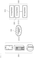
- FIG. 1 illustratively shows the configuration of the entire system for calculating a spatial coordinate point of a region of interest according to one embodiment of the invention.
- the entire system may comprise a communication network 100, a position calculation system 200, and a plurality of image modules 300.
- the communication network 100 may be implemented regardless of communication modality such as wired and wireless communications, and may be constructed from a variety of communication networks such as local area networks (LANs), metropolitan area networks (MANs), and wide area networks (WANs).
- LANs local area networks
- MANs metropolitan area networks
- WANs wide area networks
- the communication network 100 described herein may be the Internet or the World Wide Web (WWW).
- WWW World Wide Web
- the communication network 100 is not necessarily limited thereto, and may at least partially include known wired/wireless data communication networks, known telephone networks, or known wired/wireless television communication networks.
- the communication network 100 may be a wireless data communication network, at least a part of which may be implemented with a conventional communication scheme such as radio frequency (RF) communication, WiFi communication, cellular communication (e.g., Long Term Evolution (LTE) communication), Bluetooth communication (more specifically, Bluetooth Low Energy (BLE) communication), infrared communication, and ultrasonic communication.
- RF radio frequency
- WiFi Wireless Fidelity
- cellular communication e.g., Long Term Evolution (LTE) communication
- Bluetooth communication more specifically, Bluetooth Low Energy (BLE) communication
- infrared communication e.g., Bluetooth Low Energy (BLE) communication
- ultrasonic communication e.g., Bluetooth Low Energy (BLE) communication
- the position calculation system 200 may be a digital device having a memory means and a microprocessor for computing capabilities.
- the position calculation system 200 may be a server system.
- the position calculation system 200 may function to: acquire information on an in-image coordinate point of a region of interest contained in each of a plurality of images respectively photographed by the plurality of image modules 300 to be described below; specify, with reference to information on a position where at least one of the plurality of image modules 300 is installed and information on an in-image coordinate point of a target region of interest contained in an image photographed by the at least one image module, a candidate figure containing a position where the target region of interest is located in a reference space; and specify the position where the target region of interest is located in the reference space, with reference to a positional relationship between a first candidate figure of the target region of interest corresponding to a first image module 310 and a second candidate figure of the target region of interest corresponding to a second image module 320.
- the reference space may encompass a space defined in a coordinate system with respect to which the position calculation system 200 according to the invention calculate a spatial coordinate point of a region of interest.
- position calculation system 200 The configuration and functions of the position calculation system 200 according to the invention will be discussed in more detail below. Meanwhile, although the position calculation system 200 has been described as above, the above description is illustrative, and it will be apparent to those skilled in the art that at least a part of the functions or components required for the position calculation system 200 may be implemented or included in an external system (not shown), as necessary.
- the plurality of image modules 300 may be connected to the position calculation system 200 via the communication network 100, and may function to specify at least one region of interest contained in a plurality of images respectively photographed by the plurality of image modules 300, and extract information on in-image coordinate points of the specified region of interest.
- the plurality of image modules 300 may include camera modules (e.g., two-dimensional, three-dimensional, or the like), image or video sensors, and the like.
- camera modules e.g., two-dimensional, three-dimensional, or the like
- image or video sensors e.g., image or video sensors, and the like.
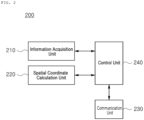
- FIG. 2 specifically shows the internal configuration of the position calculation system 200 according to one embodiment of the invention.
- the position calculation system 200 may comprise an information acquisition unit 210, a spatial coordinate calculation unit 220, a communication unit 230, and a control unit 240.
- the information acquisition unit 210, the spatial coordinate calculation unit 220, the communication unit 230, and the control unit 240 may be program modules to communicate with an external system.
- the program modules may be included in the position calculation system 200 in the form of operating systems, application program modules, and other program modules, while they may be physically stored in a variety of commonly known storage devices. Further, the program modules may also be stored in a remote storage device that may communicate with the position calculation system 200. Meanwhile, such program modules may include, but not limited to, routines, subroutines, programs, objects, components, data structures, and the like for performing specific tasks or executing specific abstract data types as will be described below in accordance with the invention.
- the information acquisition unit 210 may function to acquire information on an in-image coordinate point of a region of interest contained in each of a plurality of images respectively photographed by the plurality of image modules 300.
- the plurality of image modules 300 may specify an image corresponding to the region of interest among the plurality of images, and extract information on an in-image coordinate point of the specified region of interest.
- the information acquisition unit 210 may acquire the extracted information on the in-image coordinate point of the region of interest from each of the plurality of image modules 300.
- an image of a predetermined body part (e.g., a hand, a fingertip, an eye, or the like) of the user may be specified as an image of a region of interest.
- each of the plurality of cameras 300 may extract information on a two- or three-dimensional in-image coordinate point of the specified region of interest, and the information acquisition unit 210 may acquire the extracted information on the two- or three-dimensional coordinate point from each of the plurality of cameras 300.
- the information on the two- or three-dimensional in-image coordinate point of the region of interest may be acquired from information on in-image pixels or voxels of the region of interest.
- the spatial coordinate calculation unit 220 may function to specify, with reference to information on a position where at least one of the plurality of image modules 300 is installed and information on an in-image coordinate point of a target region of interest contained in an image photographed by the at least one image module, a candidate figure containing a position where the target region of interest is located in a reference space.
- the target region of interest may refer to at least one of a plurality of regions of interest specified by each of the plurality of image modules 300, or may encompass a region of interest specified by at least some of the plurality of image modules 300 among a plurality of regions of interest specified by the plurality of image modules 300.
- the candidate figure according to one embodiment of the invention may refer to a point, a line (which may include a vector), a surface, a body, or a set thereof.
- the spatial coordinate calculation unit 220 may specify a candidate figure containing a position where the target region of interest is located in the reference space, with respect to a position where the at least one image module is installed in the reference space.
- the spatial coordinate calculation unit 220 when a first image module 310 and a second image module 320 of the plurality of image modules 300 are two-dimensional image modules, specifies a candidate figure corresponding to each of the first image module 310 and the second image module 320, which contains a position where the target region of interest is located in the reference space, as a vector.
- the vector may be established such that an initial (or terminal) point thereof is located at a coordinate point of a position where the corresponding image module is installed in the reference space, and a terminal (or initial) point thereof is located at a coordinate point in the reference space that is transformed from an in-image coordinate point of the target region of interest corresponding to the image module, with respect to the coordinate point of the position where the image module is installed in the reference space.
- the spatial coordinate calculation unit 220 may specify a candidate figure corresponding to each of the first image module 310 and the second image module 320, which contains a position where the target region of interest is located in the reference space, as a spatial figure (e.g., a cube, a rectangular parallelepiped, a sphere, or the like).
- a spatial figure e.g., a cube, a rectangular parallelepiped, a sphere, or the like.
- the spatial coordinate calculation unit 220 may specify candidate figures corresponding to the first image module 310 and the second image module 320, which contain a position where the target region of interest is located in the reference space, as a spatial figure and a vector, respectively.
- the spatial coordinate calculation unit 220 may specify the candidate figure with further reference to information on properties of at least one of the plurality of image modules 300.
- the information on the properties of the at least one image module may include information on a resolution, an angle of view, a focal length, support for three-dimensions, and the like of the image module.
- the spatial coordinate calculation unit 220 may refer to information on an angle of view, a focal length, and the like of at least one of the plurality of image modules 300 to determine information on at least one of a transformation angle (e.g., a rotation angle), a transformation position, and a transformation shape (e.g., a spatial figure when the image module 300 is a three-dimensional image module, or a vector when the image module 300 is a two-dimensional image module) for transforming an in-image coordinate point of a target region of interest corresponding to the at least one image module to a coordinate point in the reference space, with respect to a coordinate point of a position where the at least one image module is installed in the reference space, thereby specifying a position where the target region of interest corresponding to the at least one image module is located in the reference space and a candidate figure containing the position.
- a transformation angle e.g., a rotation angle
- a transformation position e.g., a transformation position
- a transformation shape e.g.,
- the spatial coordinate calculation unit 220 may refer to information on positions where image modules other than the third image module among the plurality of image modules 300 are installed, and information on in-image coordinate points of the target region of interest contained in images photographed by the image modules other than the third image module among the plurality of image modules 300.
- the spatial coordinate calculation unit 220 may function to specify the position where the target region of interest is located in the reference space, with reference to a positional relationship between a first candidate figure of the target region of interest corresponding to the first image module 310 and a second candidate figure of the target region of interest corresponding to the second image module 320.
- the candidate figures of the first image module 310 and the second image module 320 may be specified as vectors when the first image module 310 and the second image module 320 are two-dimensional image modules, and the spatial coordinate calculation unit 220 may specify a point of intersection between a first vector of the target region of interest corresponding to the first image module 310 and a second vector of the target region of interest corresponding to the second image module 320 as the position where the target region of interest is located in the reference space.
- a midpoint of the shortest line connecting the first and second vectors may be specified as the position where the target region of interest is located in the reference space.
- the candidate figures of the first image module 310 and the second image module 320 may be specified as spatial figures when the first image module 310 and the second image module 320 are three-dimensional image modules, and the spatial coordinate calculation unit 220 may specify a region of intersection between a first spatial figure of the target region of interest corresponding to the first image module 310 and a second spatial figure of the target region of interest corresponding to the second image module 320 as the position where the target region of interest is located in the reference space.
- an average coordinate point of the first or second spatial figure may be specified as the position where the target region of interest is located in the reference space.
- a midpoint of a line connecting average coordinate points of the first and second spatial figures may be specified as the position where the target region of interest is located in the reference space.
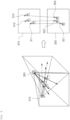
- the candidate figures of the first image module 310 and the second image module 320 are specified as a spatial figure and a vector, respectively, when the first image module 310 and the second image module 320 are a three-dimensional image module and a two-dimensional image module, respectively, and the spatial coordinate calculation unit 220 may specify a point of intersection between a third spatial figure 331, 332, 333 of the target region of interest corresponding to the first image module 310 and a third vector 341, 342, 343 of the target region of interest corresponding to the second image module 320 as the position where the target region of interest is located in the reference space. More specifically, according to one embodiment of the invention, a midpoint of the shortest line connecting the third vector 341 and an average coordinate point of the third spatial figure 331 may be specified as the position where the target region of interest is located in the reference space.
- the spatial coordinate calculation unit 220 may specify a point where the target region of interest is located in the reference space, with further reference to resolution information among the information on the properties of the image modules.
- the spatial coordinate calculation unit 220 may adaptively determine an area or volume of a candidate figure indicating the position where the target region of interest is located in the reference space, according to resolutions of the image modules.
- the spatial coordinate calculation unit 220 may refer to information on a resolution of the first image module 310 (which is a three-dimensional image module) to establish a first cube 401, a second cube 402, and a third cube 403 in the reference space, respectively, in correspondence to in-image coordinate points of a plurality of target regions of interest of the first image module 310, and may determine volumes of the above cubes (i.e., the first cube 401, the second cube 402, and the third cube 403) to be larger as the resolution of the first image module 310 is lower.
- the spatial coordinate calculation unit 220 may refer to information on a resolution of the second image module 320 (which is a two-dimensional image module) to establish a first tetragon 411, a second tetragon 421, and a third tetragon 431 in the reference space, respectively, in correspondence to in-image coordinate points of a plurality of target regions of interest of the second image module 320, and may determine areas of the above tetragons to be larger as the resolution of the second image module 320 is lower.
- a resolution of the second image module 320 which is a two-dimensional image module
- the spatial coordinate calculation unit 220 may specify the position where the target region of interest is located in the reference space, using a quadrangular pyramid (i.e., a first quadrangular pyramid, a second quadrangular pyramid, and a third quadrangular pyramid) connecting a position where the second module 320 is installed in the reference space and a tetragon in the reference space corresponding to in-image coordinate points of the target region of interest, instead of the above-described vectors of the target region of interest corresponding to the second image module 320.
- a quadrangular pyramid i.e., a first quadrangular pyramid, a second quadrangular pyramid, and a third quadrangular pyramid
- the shape of a surface that may be established in the reference space in correspondence to in-image coordinate points of the target region of interest according to the invention is not limited to a tetragon as described above, but may be changed to a circle, a triangle, a pentagon, and the like as long as the objects of the invention may be achieved.
- the shape of a solid that that may be established in the reference space in correspondence to in-image coordinate points of the target region of interest according to the invention is not limited to a cube as described above, but may be changed to a rectangular parallelepiped, a sphere, an ellipsoid, and the like.
- the spatial coordinate calculation unit 220 may specify a candidate figure whose positional relationship is to be matched with a first candidate figure of the first image module 310 (or the second image module 320) among at least one candidate figure of the second image module 320 (or the first image module 310).
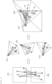
- At least one of the plurality of image modules 300 may be synchronized with each other on a frame basis, and the spatial coordinate calculation unit 220 may specify a candidate figure 521 whose positional relationship is to be matched with a first candidate figure 511 of the first image module 310 (or the second image module 320) among at least one candidate figure 521, 522, 523 of the second image module 320 (or the first image module 310) on the basis of each frame synchronized between the first image module 310 and the second image module 320.
- the information on in-image coordinate points of a region of interest which is acquired by the information acquisition unit 210 according to one embodiment of the invention, may include identification information 601, 602, 603, 604, 605, 611, 612, 613, 614, 615 that may be distinguished between the image modules or target regions of interest.
- the spatial coordinate calculation unit 220 may specify a candidate figure 611 whose positional relationship is to be matched with a first candidate figure 601 of the first image module 310 (or the second image module 320) among at least one candidate figure 611, 612, 613, 614, 615 of the second image module 320 (or the first image module 310) with reference to the identification information 601, 602, 603, 604, 605, 611, 612, 613, 614, 615.
- the identification information may include information on at least one of a shape, color, temperature, pattern, and marker (e.g., emoji, QR code, etc.) specified in the images of the region of interest.
- the spatial coordinate calculation unit 220 may specify a candidate figure whose positional relationship is to be matched with a first candidate figure of the first image module 310 (or the second image module 320) among at least one candidate figure of the second image module 320 (or the first image module 310) by specifying candidate figures that may be grouped among the candidate figures of the first image module 310 and the second image module 320.
- the spatial coordinate calculation unit 220 may group and match vectors or spatial figures within a predetermined distance from the vectors or spatial figures that do not match one-to-one.
- the spatial coordinate calculation unit 220 may specify information on a positional relationship of the plurality of imaging modules 300 with reference to coordinate points corresponding to at least three target regions of interest.
- the information on the positional relationship may include information on angles formed between the plurality of image modules 300, angles at which the plurality of image modules 300 are inclined in the reference space, and photographing directions of the plurality of image modules 300.
- the spatial coordinate calculation unit 220 may specify the information on the positional relationship of the plurality of image modules 300 with reference to at least three points (or regions) of intersection between candidate figures of the target regions of interest corresponding to the plurality of image modules 300.
- in-image coordinate points of three target regions of interest are first to third coordinate points 1001, 1002, 1003 and fourth to sixth coordinate points 1004, 1005, 1006 in the first image module 310 and the second image module 320 (which are two-dimensional image modules), respectively
- three points in the reference space may be specified where a first vector 1011, a second vector 1012, and a third vector 1013 of the target regions of interest corresponding to the first image module 310 intersect a fourth vector 1021, a fifth vector 1022, and a sixth vector 1023 of the target regions of interest corresponding to the second image module 320, so that the positional relationship between the first image module 310 and the second image module 320 may be specified on the basis of the three points.
- in-image coordinate points of three target regions of interest are seventh to ninth coordinate points and tenth to twelfth coordinate points in the first image module 310 and the second image module 320 (which are three-dimensional image modules), respectively
- three regions in the reference space may be specified where a first spatial figure, a second spatial figure, and a third spatial figure of the target regions of interest corresponding to the first image module 310 intersect a fourth spatial figure, a fifth spatial figure, and a sixth spatial figure of the target regions of interest corresponding to the second image module 320, so that the positional relationship between the first image module 310 and the second image module 320 may be specified on the basis of the three regions.
- in-image coordinate points of three target regions of interest are thirteenth to fifteenth coordinate points and sixteenth to eighteenth coordinate points in the first image module 310 and the second image module 320 (which are two-dimensional and three-dimensional image modules), respectively
- three points in the reference space may be specified where a seventh vector, a eighth vector, and a ninth vector of the target regions of interest corresponding to the first image module 310 intersect a seventh spatial figure, an eighth spatial figure, and a ninth spatial figure of the target regions of interest corresponding to the second image module 320, so that the positional relationship between the first image module 310 and the second image module 320 may be specified on the basis of the three points.
- the communication unit 230 may function to enable data transmission/reception from/to the information acquisition unit 210 and the spatial coordinate calculation unit 220.
- control unit 240 may function to control data flow among the information acquisition unit 210, the spatial coordinate calculation unit 220, and the communication unit 230. That is, the control unit 240 according to the invention may control data flow into/out of the position calculation system 200 or data flow among the respective components of the position calculation system 200, such that the information acquisition unit 210, the spatial coordinate calculation unit 220, and the communication unit 230 may carry out their particular functions, respectively.
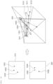
- FIG. 11 illustratively shows how to calculate a spatial coordinate point of a region of interest by the position calculation system 200 according to one embodiment of the invention.
- the spatial coordinate point of the region of interest is calculated by the first image module 310 and the second image module 320, which are two-dimensional image modules.
- the region of interest according to one embodiment of the invention may be a point 1130 of a user's finger gun.
- information on in-image coordinate points 1110 and 1120 of a region of interest 1130 contained in a plurality of images respectively photographed by the first image module 310 and the second module 320 may be acquired. That is, according to one embodiment of the invention, the position calculation system 200 does not acquire the images photographed by the first image module 310 and the second image module 320, but acquire the information on the in-image coordinate points of the region of interest contained in these images.
- vectors 1140 and 1150 containing a position where the target region of interest 1130 is located in the reference space may be specified on the basis of information on positions where the first image module 310 and the second image module 320 are installed and the information on the in-image coordinate points 1110 and 1120 of the target region of interest 1130 contained in the images photographed by the first image module 310 and the second module 320. That is, according to one embodiment of the invention, a first vector 1140 of the target region of interest 1130 corresponding to the first image module 310 in the reference space and a second vector 1150 of the target region of interest 1130 corresponding to the second image module 320 in the reference space may be specified, respectively.
- a point of intersection 1160 between the first vector 1140 and the second vector 1150 may be specified as the position where the target region of interest 1130 is located in the reference space.
- the position calculation system 200 may calculate a coordinate point 1160 corresponding to the specified position in the reference space as a spatial coordinate point of the region of interest 1130 according to the invention.
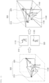
- FIG. 12 illustratively shows how to specify positions of the plurality of image modules 300 using information on physical values of an object according to one embodiment of the invention.
- the position calculation system 200 may specify coordinate points of positions where the plurality of image modules 300 are installed in the reference space, with reference to information on physical values of an object in the real world (e.g., a length, size, area, and volume of the object).
- the position calculation system 200 may specify coordinate points of positions where the first image module 310 and the second image module 320 are installed in the reference space, by determining each corner point of the object 1250 as a target region of interest to acquire information on in-image coordinate points 1201, 1202, 1203, 1204, 1205, 1206, 1207, and 1208 of the target regions of interest, and comparing and analyzing the acquired information on the coordinate points 1201, 1202, 1203, 1204, 1205, 1206, 1207, and 1208 and information on physical values (e.g., a width, depth, height, and angle) of the object 1250 in the real world.
- physical values e.g., a width, depth, height, and angle
- the position calculation system 200 may specify the coordinate points of the positions where the first image module 310 and the second image module 320 are installed in the reference space, with further reference to information on a coordinate point of each corner point of the object 1250 in the reference space.
- the embodiments according to the invention as described above may be implemented in the form of program instructions that can be executed by various computer components, and may be stored on a computer-readable recording medium.
- the computer-readable recording medium may include program instructions, data files, and data structures, separately or in combination.
- the program instructions stored on the computer-readable recording medium may be specially designed and configured for the present invention, or may also be known and available to those skilled in the computer software field.
- Examples of the computer-readable recording medium include the following: magnetic media such as hard disks, floppy disks and magnetic tapes; optical media such as compact disk-read only memory (CD-ROM) and digital versatile disks (DVDs); magneto-optical media such as floptical disks; and hardware devices such as read-only memory (ROM), random access memory (RAM) and flash memory, which are specially configured to store and execute program instructions.
- Examples of the program instructions include not only machine language codes created by a compiler, but also high-level language codes that can be executed by a computer using an interpreter.
- the above hardware devices may be changed to one or more software modules to perform the processes of the present invention, and vice versa.
Landscapes
- Engineering & Computer Science (AREA)
- Theoretical Computer Science (AREA)
- Physics & Mathematics (AREA)
- General Physics & Mathematics (AREA)
- Computer Vision & Pattern Recognition (AREA)
- Multimedia (AREA)
- Computing Systems (AREA)
- Artificial Intelligence (AREA)
- Health & Medical Sciences (AREA)
- Databases & Information Systems (AREA)
- Evolutionary Computation (AREA)
- General Health & Medical Sciences (AREA)
- Medical Informatics (AREA)
- Software Systems (AREA)
- Image Analysis (AREA)
- Image Processing (AREA)
Claims (9)
- Verfahren zum Berechnen eines räumlichen Koordinatenpunktes eines Bereichs von Interesse, wobei das Verfahren die folgenden Schritte umfasst:Erfassen von Informationen über einen In-Bild-Koordinatenpunkt eines Bereichs von Interesse, der in jedem einer Vielzahl von Bildern enthalten ist, die jeweils von einer Vielzahl von Bildmodulen (300) fotografiert wurden;Spezifizieren, unter Bezugnahme auf Informationen über eine Position, an der mindestens eines der Vielzahl von Bildmodulen (300) installiert ist, und Informationen über einen In-Bild-Koordinatenpunkt eines Zielbereichs von Interesse, der in einem von dem mindestens einen Bildmodul fotografierten Bild enthalten ist, einer Kandidatenfigur, die eine Position enthält, an der sich der Zielbereich von Interesse in einem Referenzraum befindet; undSpezifizieren der Position, an der sich der Zielbereich von Interesse in dem Referenzraum befindet, unter Bezugnahme auf eine Positionsbeziehung zwischen einer ersten Kandidatenfigur des Zielbereichs von Interesse entsprechend einem ersten Bildmodul (310) und einer zweiten Kandidatenfigur des Zielbereichs von Interesse entsprechend einem zweiten Bildmodul (320),dadurch gekennzeichnet, dass die ersten und zweiten Kandidatenfiguren als eine räumliche Figur und ein Vektor spezifiziert sind, wenn das erste Bildmodul (310) und das zweite Bildmodul (320) ein dreidimensionales Bildmodul bzw. ein zweidimensionales Bildmodul sind.
- Verfahren gemäß Anspruch 1, wobei im Schritt des Spezifizierens der Kandidatenfigur die Kandidatenfigur unter weiterer Bezugnahme auf Eigenschaften des mindestens einen Bildmoduls spezifiziert ist.
- Verfahren gemäß Anspruch 1, wobei die Position, an der sich der Zielbereich von Interesse befindet, als Schnittpunkt zwischen einer räumlichen Figur des Zielbereichs von Interesse entsprechend dem ersten Bildmodul (310), und einem Vektor des Zielbereichs von Interesse entsprechend dem zweiten Bildmodul (320) angegeben wird.
- Verfahren gemäß Anspruch 1, wobei Informationen über eine Positionsbeziehung zwischen der Vielzahl von Bildgebungsmodulen unter Bezugnahme auf Informationen über In-Bild-Koordinatenpunkte von mindestens drei Zielbereichen von Interesse spezifiziert sind.
- Verfahren gemäß Anspruch 1, wobei die erste Kandidatenfigur des ersten Bildmoduls (310) und die zweite Kandidatenfigur des zweiten Bildmoduls (320) auf der Grundlage jedes zwischen dem ersten Bildmodul (310) und dem zweiten Bildmodul (320) synchronisierten Rahmens miteinander abgeglichen werden.
- Verfahren gemäß Anspruch 1, wobei die Informationen über den In-Bild-Koordinatenpunkt des Zielbereichs von Interesse Identifikationsinformationen enthalten, die zwischen einer Vielzahl von Zielbereichen von Interesse unterscheidbar sind, und die erste Kandidatenfigur des ersten Bildmoduls (310) und die zweite Kandidatenfigur des zweiten Bildmoduls (320) auf der Grundlage der Identifikationsinformationen miteinander abgeglichen werden.
- Verfahren gemäß Anspruch 1, wobei, wenn die erste Kandidatenfigur des ersten Bildmoduls (310) und die zweite Kandidatenfigur des zweiten Bildmoduls (320) nicht eins-zu-eins übereinstimmen, Kandidatenfiguren, die zwischen der ersten Kandidatenfigur des ersten Bildmoduls (310) und der zweiten Kandidatenfigur des zweiten Bildmoduls (320) gruppiert werden können, spezifiziert und miteinander abgeglichen werden.
- Nicht-transitorisches, computerlesbares Aufzeichnungsmedium, auf dem ein Computerprogramm zum Ausführen des Verfahrens gemäß Anspruch 1 gespeichert ist.
- System zum Berechnen eines räumlichen Koordinatenpunktes eines Bereichs von Interesse, wobei das System Folgendes umfasst:eine Informationserfassungseinheit (210), die so konfiguriert ist, dass sie Informationen über einen In-Bild-Koordinatenpunkt eines Bereichs von Interesse erfasst, der in jedem einer Vielzahl von Bildern enthalten ist, die jeweils von einer Vielzahl von Bildmodulen (300) fotografiert wurden; undeine Raumkoordinatenberechnungseinheit (220), die so konfiguriert ist, dass sie unter Bezugnahme auf Informationen über eine Position, an der mindestens eines der Vielzahl von Bildmodulen (300) installiert ist, und Informationen über einen In-Bild-Koordinatenpunkt eines Zielbereichs von Interesse, der in einem von dem mindestens einen Bildmodul fotografierten Bild enthalten ist, eine Kandidatenfigur spezifiziert, die eine Position enthält, an der sich der Zielbereich von Interesse in einem Referenzraum befindet, und zum Spezifizieren der Position, an der sich der Zielbereich von Interesse in dem Referenzraum befindet, mit Bezug auf eine Positionsbeziehung zwischen einer ersten Kandidatenfigur des Zielbereichs von Interesse entsprechend einem ersten Bildmodul (310) und einer zweiten Kandidatenfigur des Zielbereichs von Interesse entsprechend einem zweiten Bildmodul (320),dadurch gekennzeichnet, dass die ersten und zweiten Kandidatenfiguren als eine räumliche Figur und ein Vektor spezifiziert sind, wenn das erste Bildmodul (310) und das zweite Bildmodul (320) ein dreidimensionales Bildmodul bzw. ein zweidimensionales Bildmodul sind.
Applications Claiming Priority (2)
| Application Number | Priority Date | Filing Date | Title |
|---|---|---|---|
| KR1020180056039A KR102072796B1 (ko) | 2018-05-16 | 2018-05-16 | 관심 영역의 공간 좌표를 산출하는 방법, 시스템 및 비일시성의 컴퓨터 판독 가능 기록 매체 |
| PCT/KR2018/010711 WO2019221340A1 (ko) | 2018-05-16 | 2018-09-12 | 관심 영역의 공간 좌표를 산출하는 방법, 시스템 및 비일시성의 컴퓨터 판독 가능 기록 매체 |
Publications (4)
| Publication Number | Publication Date |
|---|---|
| EP3796258A1 EP3796258A1 (de) | 2021-03-24 |
| EP3796258A4 EP3796258A4 (de) | 2022-02-23 |
| EP3796258C0 EP3796258C0 (de) | 2024-12-18 |
| EP3796258B1 true EP3796258B1 (de) | 2024-12-18 |
Family
ID=68540534
Family Applications (1)
| Application Number | Title | Priority Date | Filing Date |
|---|---|---|---|
| EP18919225.5A Active EP3796258B1 (de) | 2018-05-16 | 2018-09-12 | Verfahren und system zur berechnung räumlicher koordinaten eines interessierenden bereichs und nichttransitorisches computerlesbares aufzeichnungsmedium |
Country Status (6)
| Country | Link |
|---|---|
| US (1) | US11321867B2 (de) |
| EP (1) | EP3796258B1 (de) |
| JP (1) | JP7161550B2 (de) |
| KR (1) | KR102072796B1 (de) |
| CN (2) | CN120431175A (de) |
| WO (1) | WO2019221340A1 (de) |
Families Citing this family (6)
| Publication number | Priority date | Publication date | Assignee | Title |
|---|---|---|---|---|
| KR102409398B1 (ko) | 2020-09-15 | 2022-06-15 | 김학민 | 입체도형을 이용한 삼차원 공간 위치 좌표화 방법 |
| CN113516131A (zh) * | 2020-12-24 | 2021-10-19 | 阿里巴巴集团控股有限公司 | 图像处理方法、装置、设备和存储介质 |
| CN113591852B (zh) * | 2021-08-09 | 2022-08-23 | 数坤(北京)网络科技股份有限公司 | 感兴趣区域标记的方法和装置 |
| CN115861047B (zh) * | 2021-09-23 | 2025-11-25 | 中移(上海)信息通信科技有限公司 | 一种遥感影像坐标系转换的控制方法、装置及终端 |
| CN113947758B (zh) * | 2021-12-16 | 2022-04-29 | 北京凯泰铭科技文化发展有限公司 | 一种基于景区棋盘划分的海绵体系的大数据方法和系统 |
| CN114677429B (zh) * | 2022-05-27 | 2022-08-30 | 深圳广成创新技术有限公司 | 一种机械手的定位方法、装置、计算机设备和存储介质 |
Family Cites Families (10)
| Publication number | Priority date | Publication date | Assignee | Title |
|---|---|---|---|---|
| JP4357030B2 (ja) * | 1999-05-21 | 2009-11-04 | トヨタ自動車株式会社 | 空間図形入力装置 |
| KR100836740B1 (ko) * | 2006-08-28 | 2008-06-10 | 계명대학교 산학협력단 | 영상 데이터 처리 방법 및 그에 따른 시스템 |
| KR101285360B1 (ko) * | 2007-01-25 | 2013-07-11 | 삼성전자주식회사 | 증강현실을 이용한 관심 지점 표시 장치 및 방법 |
| US8253778B2 (en) * | 2008-03-21 | 2012-08-28 | Takahashi Atsushi | Three-dimensional digital magnifier operation supporting system |
| KR101681538B1 (ko) * | 2010-10-20 | 2016-12-01 | 삼성전자주식회사 | 영상 처리 장치 및 방법 |
| US9188973B2 (en) * | 2011-07-08 | 2015-11-17 | Restoration Robotics, Inc. | Calibration and transformation of a camera system's coordinate system |
| KR101533319B1 (ko) * | 2014-02-22 | 2015-07-03 | 주식회사 브이터치 | 카메라 중심의 가상터치를 이용한 원격 조작 장치 및 방법 |
| KR101712925B1 (ko) * | 2015-04-09 | 2017-03-07 | 한국항공대학교산학협력단 | 영상과 위치정보를 연계한 데이터베이스를 구축하는 방법, 상기 데이터베이스를 활용하여 측위하는 방법, 및 상기 방법들을 수행하는 전자 장치 |
| KR102687690B1 (ko) * | 2016-08-08 | 2024-07-23 | 한화비전 주식회사 | 영상 처리 장치 및 영상 처리 방법 |
| CN107274455A (zh) * | 2017-07-07 | 2017-10-20 | 东北林业大学 | 混合视觉系统中全景图形的三维重建方法 |
-
2018
- 2018-05-16 KR KR1020180056039A patent/KR102072796B1/ko active Active
- 2018-09-12 JP JP2020564363A patent/JP7161550B2/ja active Active
- 2018-09-12 WO PCT/KR2018/010711 patent/WO2019221340A1/ko not_active Ceased
- 2018-09-12 CN CN202510524918.4A patent/CN120431175A/zh active Pending
- 2018-09-12 CN CN201880094998.2A patent/CN112313706B/zh active Active
- 2018-09-12 EP EP18919225.5A patent/EP3796258B1/de active Active
-
2020
- 2020-11-13 US US17/097,300 patent/US11321867B2/en active Active
Also Published As
| Publication number | Publication date |
|---|---|
| KR20190131320A (ko) | 2019-11-26 |
| EP3796258A1 (de) | 2021-03-24 |
| JP2021523488A (ja) | 2021-09-02 |
| EP3796258C0 (de) | 2024-12-18 |
| US11321867B2 (en) | 2022-05-03 |
| CN112313706B (zh) | 2025-05-16 |
| EP3796258A4 (de) | 2022-02-23 |
| WO2019221340A1 (ko) | 2019-11-21 |
| CN112313706A (zh) | 2021-02-02 |
| US20210065397A1 (en) | 2021-03-04 |
| KR102072796B9 (ko) | 2021-10-27 |
| KR102072796B1 (ko) | 2020-02-03 |
| JP7161550B2 (ja) | 2022-10-26 |
| CN120431175A (zh) | 2025-08-05 |
Similar Documents
| Publication | Publication Date | Title |
|---|---|---|
| EP3796258B1 (de) | Verfahren und system zur berechnung räumlicher koordinaten eines interessierenden bereichs und nichttransitorisches computerlesbares aufzeichnungsmedium | |
| US12051223B2 (en) | Positioning method, electronic device, and storage medium | |
| Huang et al. | WiFi and vision-integrated fingerprint for smartphone-based self-localization in public indoor scenes | |
| Paucher et al. | Location-based augmented reality on mobile phones | |
| KR102398478B1 (ko) | 전자 디바이스 상에서의 환경 맵핑을 위한 피쳐 데이터 관리 | |
| CN109725645A (zh) | 一种嵌套式无人机着陆合作标志设计及相对位姿获取方法 | |
| CN109540144A (zh) | 一种室内定位方法及装置 | |
| EP2912631A1 (de) | Positionsbestimmung aus bildern und zugehörige kamerapositionen | |
| WO2011047888A1 (en) | Method of providing a descriptor for at least one feature of an image and method of matching features | |
| CN108171715B (zh) | 一种图像分割方法及装置 | |
| CN104820998A (zh) | 一种基于无人机动平台的人体检测与跟踪方法及装置 | |
| KR101885961B1 (ko) | 이미지를 기반으로 한 객체 위치 추정 방법 및 장치 | |
| CN106289263A (zh) | 室内导航方法和装置 | |
| Yeh et al. | 3D reconstruction and visual SLAM of indoor scenes for augmented reality application | |
| Li et al. | Multiple RGB-D sensor-based 3-D reconstruction and localization of indoor environment for mini MAV | |
| Jóźków et al. | Combined matching of 2d and 3d kinect™ data to support indoor mapping and navigation | |
| CN117057086B (zh) | 基于目标识别与模型匹配的三维重建方法、装置及设备 | |
| KR102398404B1 (ko) | 객체 제어를 지원하기 위한 방법, 시스템 및 비일시성의 컴퓨터 판독 가능 기록 매체 | |
| KR102483388B1 (ko) | 전방위 이미지 처리 방법 및 이를 수행하는 서버 | |
| US20240312056A1 (en) | Method and system for determining a three dimensional position | |
| WO2018070895A1 (ru) | Система позиционирования объекта в пространстве для виртуальной реальности. | |
| Marquis et al. | Use of Dynamic Pose to Enhance Passive Visual Tracking | |
| CN116051628A (zh) | 一种无人机定位方法、装置、电子设备以及存储介质 | |
| Jarvis | Robot Vision | |
| He | A Probabilistic Framework for Multi-Sensor Fusion Based Indoor Localization on Mobile Platform |
Legal Events
| Date | Code | Title | Description |
|---|---|---|---|
| STAA | Information on the status of an ep patent application or granted ep patent |
Free format text: STATUS: THE INTERNATIONAL PUBLICATION HAS BEEN MADE |
|
| PUAI | Public reference made under article 153(3) epc to a published international application that has entered the european phase |
Free format text: ORIGINAL CODE: 0009012 |
|
| STAA | Information on the status of an ep patent application or granted ep patent |
Free format text: STATUS: REQUEST FOR EXAMINATION WAS MADE |
|
| 17P | Request for examination filed |
Effective date: 20201130 |
|
| AK | Designated contracting states |
Kind code of ref document: A1 Designated state(s): AL AT BE BG CH CY CZ DE DK EE ES FI FR GB GR HR HU IE IS IT LI LT LU LV MC MK MT NL NO PL PT RO RS SE SI SK SM TR |
|
| AX | Request for extension of the european patent |
Extension state: BA ME |
|
| DAV | Request for validation of the european patent (deleted) | ||
| DAX | Request for extension of the european patent (deleted) | ||
| A4 | Supplementary search report drawn up and despatched |
Effective date: 20220121 |
|
| RIC1 | Information provided on ipc code assigned before grant |
Ipc: G06F 3/048 20130101ALI20220118BHEP Ipc: G06K 9/62 20060101ALI20220118BHEP Ipc: G06V 10/25 20220101ALI20220118BHEP Ipc: G06T 7/70 20170101ALI20220118BHEP Ipc: G06T 7/30 20170101AFI20220118BHEP |
|
| GRAP | Despatch of communication of intention to grant a patent |
Free format text: ORIGINAL CODE: EPIDOSNIGR1 |
|
| STAA | Information on the status of an ep patent application or granted ep patent |
Free format text: STATUS: GRANT OF PATENT IS INTENDED |
|
| RIC1 | Information provided on ipc code assigned before grant |
Ipc: G06F 3/048 20130101ALI20240611BHEP Ipc: G06V 10/25 20220101ALI20240611BHEP Ipc: G06T 7/73 20170101ALI20240611BHEP Ipc: G06T 7/30 20170101AFI20240611BHEP |
|
| INTG | Intention to grant announced |
Effective date: 20240710 |
|
| GRAS | Grant fee paid |
Free format text: ORIGINAL CODE: EPIDOSNIGR3 |
|
| GRAA | (expected) grant |
Free format text: ORIGINAL CODE: 0009210 |
|
| STAA | Information on the status of an ep patent application or granted ep patent |
Free format text: STATUS: THE PATENT HAS BEEN GRANTED |
|
| AK | Designated contracting states |
Kind code of ref document: B1 Designated state(s): AL AT BE BG CH CY CZ DE DK EE ES FI FR GB GR HR HU IE IS IT LI LT LU LV MC MK MT NL NO PL PT RO RS SE SI SK SM TR |
|
| REG | Reference to a national code |
Ref country code: CH Ref legal event code: EP |
|
| REG | Reference to a national code |
Ref country code: DE Ref legal event code: R096 Ref document number: 602018077834 Country of ref document: DE |
|
| REG | Reference to a national code |
Ref country code: IE Ref legal event code: FG4D |
|
| U01 | Request for unitary effect filed |
Effective date: 20250113 |
|
| U07 | Unitary effect registered |
Designated state(s): AT BE BG DE DK EE FI FR IT LT LU LV MT NL PT RO SE SI Effective date: 20250117 |
|
| PG25 | Lapsed in a contracting state [announced via postgrant information from national office to epo] |
Ref country code: HR Free format text: LAPSE BECAUSE OF FAILURE TO SUBMIT A TRANSLATION OF THE DESCRIPTION OR TO PAY THE FEE WITHIN THE PRESCRIBED TIME-LIMIT Effective date: 20241218 |
|
| PG25 | Lapsed in a contracting state [announced via postgrant information from national office to epo] |
Ref country code: NO Free format text: LAPSE BECAUSE OF FAILURE TO SUBMIT A TRANSLATION OF THE DESCRIPTION OR TO PAY THE FEE WITHIN THE PRESCRIBED TIME-LIMIT Effective date: 20250318 |
|
| PG25 | Lapsed in a contracting state [announced via postgrant information from national office to epo] |
Ref country code: GR Free format text: LAPSE BECAUSE OF FAILURE TO SUBMIT A TRANSLATION OF THE DESCRIPTION OR TO PAY THE FEE WITHIN THE PRESCRIBED TIME-LIMIT Effective date: 20250319 |
|
| PG25 | Lapsed in a contracting state [announced via postgrant information from national office to epo] |
Ref country code: RS Free format text: LAPSE BECAUSE OF FAILURE TO SUBMIT A TRANSLATION OF THE DESCRIPTION OR TO PAY THE FEE WITHIN THE PRESCRIBED TIME-LIMIT Effective date: 20250318 |
|
| PG25 | Lapsed in a contracting state [announced via postgrant information from national office to epo] |
Ref country code: SM Free format text: LAPSE BECAUSE OF FAILURE TO SUBMIT A TRANSLATION OF THE DESCRIPTION OR TO PAY THE FEE WITHIN THE PRESCRIBED TIME-LIMIT Effective date: 20241218 |
|
| PG25 | Lapsed in a contracting state [announced via postgrant information from national office to epo] |
Ref country code: PL Free format text: LAPSE BECAUSE OF FAILURE TO SUBMIT A TRANSLATION OF THE DESCRIPTION OR TO PAY THE FEE WITHIN THE PRESCRIBED TIME-LIMIT Effective date: 20241218 |
|
| PG25 | Lapsed in a contracting state [announced via postgrant information from national office to epo] |
Ref country code: ES Free format text: LAPSE BECAUSE OF FAILURE TO SUBMIT A TRANSLATION OF THE DESCRIPTION OR TO PAY THE FEE WITHIN THE PRESCRIBED TIME-LIMIT Effective date: 20241218 |
|
| PG25 | Lapsed in a contracting state [announced via postgrant information from national office to epo] |
Ref country code: IS Free format text: LAPSE BECAUSE OF FAILURE TO SUBMIT A TRANSLATION OF THE DESCRIPTION OR TO PAY THE FEE WITHIN THE PRESCRIBED TIME-LIMIT Effective date: 20250418 |
|
| PG25 | Lapsed in a contracting state [announced via postgrant information from national office to epo] |
Ref country code: SK Free format text: LAPSE BECAUSE OF FAILURE TO SUBMIT A TRANSLATION OF THE DESCRIPTION OR TO PAY THE FEE WITHIN THE PRESCRIBED TIME-LIMIT Effective date: 20241218 |
|
| PG25 | Lapsed in a contracting state [announced via postgrant information from national office to epo] |
Ref country code: CZ Free format text: LAPSE BECAUSE OF FAILURE TO SUBMIT A TRANSLATION OF THE DESCRIPTION OR TO PAY THE FEE WITHIN THE PRESCRIBED TIME-LIMIT Effective date: 20241218 |
|
| U20 | Renewal fee for the european patent with unitary effect paid |
Year of fee payment: 8 Effective date: 20250909 |
|
| PLBE | No opposition filed within time limit |
Free format text: ORIGINAL CODE: 0009261 |
|
| STAA | Information on the status of an ep patent application or granted ep patent |
Free format text: STATUS: NO OPPOSITION FILED WITHIN TIME LIMIT |
|
| 26N | No opposition filed |
Effective date: 20250919 |