EP3796136A1 - Position indication device and information processing device - Google Patents
Position indication device and information processing device Download PDFInfo
- Publication number
- EP3796136A1 EP3796136A1 EP19804098.2A EP19804098A EP3796136A1 EP 3796136 A1 EP3796136 A1 EP 3796136A1 EP 19804098 A EP19804098 A EP 19804098A EP 3796136 A1 EP3796136 A1 EP 3796136A1
- Authority
- EP
- European Patent Office
- Prior art keywords
- pressure
- sensor
- position indicating
- pen
- gripping force
- Prior art date
- Legal status (The legal status is an assumption and is not a legal conclusion. Google has not performed a legal analysis and makes no representation as to the accuracy of the status listed.)
- Granted
Links
Images




Classifications
-
- G—PHYSICS
- G06—COMPUTING OR CALCULATING; COUNTING
- G06F—ELECTRIC DIGITAL DATA PROCESSING
- G06F3/00—Input arrangements for transferring data to be processed into a form capable of being handled by the computer; Output arrangements for transferring data from processing unit to output unit, e.g. interface arrangements
- G06F3/01—Input arrangements or combined input and output arrangements for interaction between user and computer
- G06F3/03—Arrangements for converting the position or the displacement of a member into a coded form
- G06F3/0304—Detection arrangements using opto-electronic means
- G06F3/0317—Detection arrangements using opto-electronic means in co-operation with a patterned surface, e.g. absolute position or relative movement detection for an optical mouse or pen positioned with respect to a coded surface
-
- G—PHYSICS
- G06—COMPUTING OR CALCULATING; COUNTING
- G06F—ELECTRIC DIGITAL DATA PROCESSING
- G06F3/00—Input arrangements for transferring data to be processed into a form capable of being handled by the computer; Output arrangements for transferring data from processing unit to output unit, e.g. interface arrangements
- G06F3/01—Input arrangements or combined input and output arrangements for interaction between user and computer
- G06F3/03—Arrangements for converting the position or the displacement of a member into a coded form
- G06F3/033—Pointing devices displaced or positioned by the user, e.g. mice, trackballs, pens or joysticks; Accessories therefor
- G06F3/0354—Pointing devices displaced or positioned by the user, e.g. mice, trackballs, pens or joysticks; Accessories therefor with detection of two-dimensional [2D] relative movements between the device, or an operating part thereof, and a plane or surface, e.g. 2D mice, trackballs, pens or pucks
- G06F3/03545—Pens or stylus
-
- G—PHYSICS
- G06—COMPUTING OR CALCULATING; COUNTING
- G06F—ELECTRIC DIGITAL DATA PROCESSING
- G06F3/00—Input arrangements for transferring data to be processed into a form capable of being handled by the computer; Output arrangements for transferring data from processing unit to output unit, e.g. interface arrangements
- G06F3/01—Input arrangements or combined input and output arrangements for interaction between user and computer
- G06F3/011—Arrangements for interaction with the human body, e.g. for user immersion in virtual reality
-
- G—PHYSICS
- G06—COMPUTING OR CALCULATING; COUNTING
- G06F—ELECTRIC DIGITAL DATA PROCESSING
- G06F3/00—Input arrangements for transferring data to be processed into a form capable of being handled by the computer; Output arrangements for transferring data from processing unit to output unit, e.g. interface arrangements
- G06F3/01—Input arrangements or combined input and output arrangements for interaction between user and computer
- G06F3/03—Arrangements for converting the position or the displacement of a member into a coded form
- G06F3/0304—Detection arrangements using opto-electronic means
-
- G—PHYSICS
- G06—COMPUTING OR CALCULATING; COUNTING
- G06F—ELECTRIC DIGITAL DATA PROCESSING
- G06F3/00—Input arrangements for transferring data to be processed into a form capable of being handled by the computer; Output arrangements for transferring data from processing unit to output unit, e.g. interface arrangements
- G06F3/01—Input arrangements or combined input and output arrangements for interaction between user and computer
- G06F3/03—Arrangements for converting the position or the displacement of a member into a coded form
- G06F3/033—Pointing devices displaced or positioned by the user, e.g. mice, trackballs, pens or joysticks; Accessories therefor
- G06F3/0346—Pointing devices displaced or positioned by the user, e.g. mice, trackballs, pens or joysticks; Accessories therefor with detection of the device orientation or free movement in a three-dimensional [3D] space, e.g. 3D mice, 6-DOF [six degrees of freedom] pointers using gyroscopes, accelerometers or tilt-sensors
-
- G—PHYSICS
- G06—COMPUTING OR CALCULATING; COUNTING
- G06F—ELECTRIC DIGITAL DATA PROCESSING
- G06F3/00—Input arrangements for transferring data to be processed into a form capable of being handled by the computer; Output arrangements for transferring data from processing unit to output unit, e.g. interface arrangements
- G06F3/01—Input arrangements or combined input and output arrangements for interaction between user and computer
- G06F3/03—Arrangements for converting the position or the displacement of a member into a coded form
- G06F3/033—Pointing devices displaced or positioned by the user, e.g. mice, trackballs, pens or joysticks; Accessories therefor
- G06F3/0354—Pointing devices displaced or positioned by the user, e.g. mice, trackballs, pens or joysticks; Accessories therefor with detection of two-dimensional [2D] relative movements between the device, or an operating part thereof, and a plane or surface, e.g. 2D mice, trackballs, pens or pucks
- G06F3/03545—Pens or stylus
- G06F3/03546—Pens or stylus using a rotatable ball at the tip as position detecting member
-
- G—PHYSICS
- G06—COMPUTING OR CALCULATING; COUNTING
- G06F—ELECTRIC DIGITAL DATA PROCESSING
- G06F3/00—Input arrangements for transferring data to be processed into a form capable of being handled by the computer; Output arrangements for transferring data from processing unit to output unit, e.g. interface arrangements
- G06F3/01—Input arrangements or combined input and output arrangements for interaction between user and computer
- G06F3/03—Arrangements for converting the position or the displacement of a member into a coded form
- G06F3/041—Digitisers, e.g. for touch screens or touch pads, characterised by the transducing means
- G06F3/0414—Digitisers, e.g. for touch screens or touch pads, characterised by the transducing means using force sensing means to determine a position
- G06F3/04146—Digitisers, e.g. for touch screens or touch pads, characterised by the transducing means using force sensing means to determine a position using pressure sensitive conductive elements delivering a boolean signal and located between crossing sensing lines, e.g. located between X and Y sensing line layers
-
- G—PHYSICS
- G06—COMPUTING OR CALCULATING; COUNTING
- G06F—ELECTRIC DIGITAL DATA PROCESSING
- G06F3/00—Input arrangements for transferring data to be processed into a form capable of being handled by the computer; Output arrangements for transferring data from processing unit to output unit, e.g. interface arrangements
- G06F3/01—Input arrangements or combined input and output arrangements for interaction between user and computer
- G06F3/03—Arrangements for converting the position or the displacement of a member into a coded form
- G06F3/041—Digitisers, e.g. for touch screens or touch pads, characterised by the transducing means
- G06F3/0416—Control or interface arrangements specially adapted for digitisers
- G06F3/04162—Control or interface arrangements specially adapted for digitisers for exchanging data with external devices, e.g. smart pens, via the digitiser sensing hardware
-
- G—PHYSICS
- G06—COMPUTING OR CALCULATING; COUNTING
- G06F—ELECTRIC DIGITAL DATA PROCESSING
- G06F3/00—Input arrangements for transferring data to be processed into a form capable of being handled by the computer; Output arrangements for transferring data from processing unit to output unit, e.g. interface arrangements
- G06F3/01—Input arrangements or combined input and output arrangements for interaction between user and computer
- G06F3/048—Interaction techniques based on graphical user interfaces [GUI]
- G06F3/0481—Interaction techniques based on graphical user interfaces [GUI] based on specific properties of the displayed interaction object or a metaphor-based environment, e.g. interaction with desktop elements like windows or icons, or assisted by a cursor's changing behaviour or appearance
- G06F3/04815—Interaction with a metaphor-based environment or interaction object displayed as three-dimensional [3D], e.g. changing the user viewpoint with respect to the environment or object
-
- G—PHYSICS
- G06—COMPUTING OR CALCULATING; COUNTING
- G06F—ELECTRIC DIGITAL DATA PROCESSING
- G06F3/00—Input arrangements for transferring data to be processed into a form capable of being handled by the computer; Output arrangements for transferring data from processing unit to output unit, e.g. interface arrangements
- G06F3/01—Input arrangements or combined input and output arrangements for interaction between user and computer
- G06F3/048—Interaction techniques based on graphical user interfaces [GUI]
- G06F3/0484—Interaction techniques based on graphical user interfaces [GUI] for the control of specific functions or operations, e.g. selecting or manipulating an object, an image or a displayed text element, setting a parameter value or selecting a range
- G06F3/04845—Interaction techniques based on graphical user interfaces [GUI] for the control of specific functions or operations, e.g. selecting or manipulating an object, an image or a displayed text element, setting a parameter value or selecting a range for image manipulation, e.g. dragging, rotation, expansion or change of colour
-
- G—PHYSICS
- G06—COMPUTING OR CALCULATING; COUNTING
- G06F—ELECTRIC DIGITAL DATA PROCESSING
- G06F3/00—Input arrangements for transferring data to be processed into a form capable of being handled by the computer; Output arrangements for transferring data from processing unit to output unit, e.g. interface arrangements
- G06F3/01—Input arrangements or combined input and output arrangements for interaction between user and computer
- G06F3/048—Interaction techniques based on graphical user interfaces [GUI]
- G06F3/0487—Interaction techniques based on graphical user interfaces [GUI] using specific features provided by the input device, e.g. functions controlled by the rotation of a mouse with dual sensing arrangements, or of the nature of the input device, e.g. tap gestures based on pressure sensed by a digitiser
- G06F3/0488—Interaction techniques based on graphical user interfaces [GUI] using specific features provided by the input device, e.g. functions controlled by the rotation of a mouse with dual sensing arrangements, or of the nature of the input device, e.g. tap gestures based on pressure sensed by a digitiser using a touch-screen or digitiser, e.g. input of commands through traced gestures
- G06F3/04883—Interaction techniques based on graphical user interfaces [GUI] using specific features provided by the input device, e.g. functions controlled by the rotation of a mouse with dual sensing arrangements, or of the nature of the input device, e.g. tap gestures based on pressure sensed by a digitiser using a touch-screen or digitiser, e.g. input of commands through traced gestures for inputting data by handwriting, e.g. gesture or text
-
- G—PHYSICS
- G06—COMPUTING OR CALCULATING; COUNTING
- G06F—ELECTRIC DIGITAL DATA PROCESSING
- G06F2203/00—Indexing scheme relating to G06F3/00 - G06F3/048
- G06F2203/041—Indexing scheme relating to G06F3/041 - G06F3/045
- G06F2203/04105—Pressure sensors for measuring the pressure or force exerted on the touch surface without providing the touch position
-
- G—PHYSICS
- G06—COMPUTING OR CALCULATING; COUNTING
- G06F—ELECTRIC DIGITAL DATA PROCESSING
- G06F3/00—Input arrangements for transferring data to be processed into a form capable of being handled by the computer; Output arrangements for transferring data from processing unit to output unit, e.g. interface arrangements
- G06F3/01—Input arrangements or combined input and output arrangements for interaction between user and computer
- G06F3/03—Arrangements for converting the position or the displacement of a member into a coded form
- G06F3/041—Digitisers, e.g. for touch screens or touch pads, characterised by the transducing means
Definitions
- the present invention relates to a position indicating device and an information processing device, and particularly, to a pen-type position indicating device in use for indicating both a position in a touch surface and a position in a space, and an information processing device that is connected to such a position indicating device.
- a pen-type position indicating device (hereinafter referred to as an "electronic pen") that is used in combination with a tablet-type computer has attracted attention.
- This type of electronic pen is usually provided with a pen pressure sensor that detects a pressure (pen pressure) applied to a pen tip.
- pen pressure pen pressure
- the computer detects the position of the electronic pen in a touch surface
- the computer receives a pen pressure value from the electronic pen.
- the computer draws a line image according to the detected position
- the computer controls a line width and transparency of the line image according to the received pen pressure value.
- This configuration can produce the feel of writing similar to that of an existing pen that ejects ink, for example, draw a thicker line as the force with which the pen tip is pressed against the touch surface is greater.
- Patent Document 1 discloses a pen-type input device that does not require a touch surface.
- This pen-type input device includes a pressure sensor on its side surface and is capable of detecting a gripping force of the user.
- a characteristic corresponding to the character or the figure to be drawn appears in a change in the gripping force.
- the technique of Patent Document 1 recognizes this characteristic as the character or the figure, thereby enabling an input of the character or the figure without detecting the position of a pen tip in the touch surface.
- Patent Document 1 Japanese Patent Laid-Open No. Hei 8-6710
- the inventors of the present application consider how to make it possible to write a character and draw a picture on a virtual plane in a virtual reality (including VR: Virtual Reality, AR: Augmented Reality, and MR: Mixed Reality) space using the electronic pen described above.
- the pen pressure value cannot be detected by the above-described pen pressure sensor. Without the pen pressure value, it is not possible to control the line width and the transparency according to the pen pressure value, and therefore, it is not possible to produce the feel of writing similar to that of an existing pen. Accordingly, there has been a need for another method that can control the line width and the transparency in a preferable manner.
- one of objects of the present invention is to provide a position indicating device and an information processing device capable of controlling the line width and the transparency in a preferable manner even when there is no actual touch surface.
- a position indicating device includes a housing, a position indicating portion configured to indicate a position, a first sensor configured to detect a first pressure applied to the position indicating portion, a second sensor configured to detect a second pressure applied to the housing, a first communication unit configured to transmit the first pressure detected by the first sensor, and a second communication unit configured to transmit the second pressure detected by the second sensor.
- the position indicating device may be a position indicating device including a cylindrical external housing accommodating a position indicating portion for indicating a position in an input surface of a plane position sensor, a spatial position detection unit configured to detect spatial position information for indicating a position of the position indicating device in a space through interaction with an external device, a pressure sensor configured to detect a force on the external housing, and a processing unit configured to output the spatial position information detected by the spatial position detection unit, plane position information for indicating the position of the position indicating portion in the input surface, and pressure information regarding the force detected by the pressure sensor.
- An information processing device is capable of communicating with a position indicating device including a housing, a position indicating portion configured to indicate a position, and a pressure sensor configured to detect a force applied to the housing.
- the information processing device includes a communication unit configured to receive a pressure detected by the pressure sensor, and a controller configured to control generation of a 3D (Three-Dimensional) object in a virtual reality space based on a position of the position indicating device in a space and the pressure received by the communication unit.
- 3D ThreeD
- the information processing device may be a computer that is configured to be connected to a position indicating device including a cylindrical external housing accommodating a position indicating portion configured to indicate a position in an input surface of a plane position sensor, and a pressure sensor configured to detect a force applied to a surface of the external housing, that is configured to receive, from the position indicating device, spatial position information for indicating a position of the position indicating device in a space, plane position information for indicating the position of the position indicating portion in the input surface, and pressure information regarding the force detected by the pressure sensor, that is configured to, when the spatial position information and the pressure information have been received, detect a spatial position indicating the position of the position indicating device in the space based on the received spatial position information and perform 3D drawing based on the detected spatial position and the received pressure information, and that is configured to, when the plane position information and the pressure information have been received, detect a plane position indicating the position of the position indicating portion in the touch surface based on the received plane position information and
- the position indicating device capable of transmitting a pressure detected by a pressure sensor and the information processing device according to the present invention capable of performing 3D drawing based on the pressure detected by the pressure sensor can control the line width and the transparency in a preferable manner even when there is no actual touch surface.
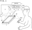
- FIG. 1 is a diagram illustrating a configuration of a spatial position indicating system 1 according to an embodiment of the present invention.
- the spatial position indicating system 1 includes a computer 2, a virtual reality display 3, a plane position sensor 4, an electronic pen 5, position detection devices 7a and 7b, and spatial position sensors 8a to 8c.
- the spatial position sensors 8a to 8c are provided in the plane position sensor 4, the virtual reality display 3, and the electronic pen 5, respectively.
- each device illustrated in FIG. 1 is provided in a room.
- the spatial position indicating system 1 almost the entire room can be used as a virtual reality space.
- the computer 2 includes a control unit 2a and a memory 2b. Each processing performed by the computer 2 described below is performed by the control unit 2a reading and executing a program stored in the memory 2b.
- the computer 2 is connected to each of the virtual reality display 3, the position detection devices 7a and 7b, and the plane position sensor 4 by wire or wirelessly.
- wired communication it is preferable to use a USB (Universal Serial Bus), for example.
- wireless communication it is preferable to use a wireless LAN (Local Area Network) such as Wi-Fi (Wireless Fidelity) (registered trademark) or near-field communication such as Bluetooth (registered trademark), for example.
- Wi-Fi Wireless Fidelity
- Bluetooth registered trademark
- the computer 2 has a function of displaying a virtual reality space on the virtual reality display 3.
- This virtual reality space may be a VR (Virtual Reality) space, an AR (Augmented Reality) space, or an MR (Mixed Reality) space.
- VR Virtual Reality
- AR Augmented Reality
- MR Magnetic Reality
- the computer 2 functions as a rendering device that renders various 3D objects in the virtual reality space set with the positions of the position detection devices 7a and 7b as a reference.
- the computer 2 also updates the display of the virtual reality display 3 according to the result of the rendering. Accordingly, various 3D objects appear in the virtual reality space displayed on the virtual reality display 3.
- the computer 2 performs rendering based on 3D object information stored in the memory 2b.
- the 3D object information indicates the shape, position, and orientation of the corresponding 3D object in the virtual reality space indicating the virtual reality space set by the computer 2 and is stored in the memory 2b for each 3D object to be rendered.
- the 3D objects rendered by the computer 2 include 3D objects such as the plane position sensor 4 and the electronic pen 5 illustrated in FIG. 1 that also exist in reality (hereinafter referred to as "first 3D objects") and 3D objects such as a virtual tablet (not illustrated) that do not exist in reality (hereinafter referred to as "second 3D objects").
- first 3D objects 3D objects
- second 3D objects 3D objects
- the computer 2 first detects the position and orientation of the spatial position sensor 8b in the real space and acquires viewpoint information indicating the viewpoint of the user based on the result of the detection.
- the computer 2 When rendering first 3D objects, the computer 2 further detects the positions and orientations of the spatial position sensors (e.g., the spatial position sensors 8a and 8c) in the real space, which are mounted in the respective objects, and stores the result of the detection in the memory 2b. Then, the computer 2 renders the first 3D objects in the virtual reality space based on the stored positions and orientations, the above-described viewpoint information, and the shapes stored for the first 3D objects.
- the spatial position sensors e.g., the spatial position sensors 8a and 8c
- the computer 2 performs processes of detecting the position of the spatial position sensor 8c to detect an operation performed by the user in the virtual reality space, and based on the result, newly creating a second 3D object (that is, newly storing 3D object information in the memory 2b) or moving or updating a second 3D object that is already held (that is, updating 3D object information that is already stored in the memory 2b).
- the computer 2 when rendering a second 3D object, the computer 2 renders the second 3D object in the virtual reality space based on the corresponding 3D object information stored in the memory 2b and the above-described viewpoint information.
- the virtual reality display 3 is a VR display (head-mounted display) that is worn on the head of a human when used. While there are various types of commercially available virtual reality displays such as "a transmissive type” or “a non-transmissive type” or “a glasses type” or “a hat type,” any of these virtual reality displays can be used as the virtual reality display 3.
- the virtual reality display 3 is connected to each of the spatial position sensors 8a and the electronic pen 5 (including the spatial position sensor 8c) by wire or wirelessly. Through this connection, each of the spatial position sensors 8a and 8c notifies the virtual reality display 3 of light reception level information described later.
- the virtual reality display 3 notifies the computer 2 of the light reception level information notified by each of the spatial position sensors 8a and 8c, together with light reception level information of the spatial position sensor 8b incorporated in the virtual reality display 3.
- the computer 2 detects the position and orientation of each of the spatial position sensors 8a to 8c in the real space based on the corresponding light reception level information notified in this manner.
- the plane position sensor 4 is a device including an input surface 4a and a plurality of electrodes (not illustrated) arranged so as to cover the entire input surface 4a.
- the input surface 4a is preferably a flat surface and can be made of a material suitable for a pen tip of the electronic pen 5 to slide thereon.
- the plurality of electrodes plays a role of detecting a pen signal (described later) transmitted by the electronic pen 5.
- the pen signal detected by each electrode is supplied to the computer 2. Based on the supplied pen signal, the computer 2 acquires the position indicated by the electronic pen 5 in the input surface 4a and various kinds of data transmitted by the electronic pen 5.
- the plane position sensor 4 may be incorporated in a tablet terminal having a display function and a processor, for example. In this case, the processor of the tablet terminal can constitute a part of or the entire computer 2.
- the spatial position sensors 8a are fixedly installed on a surface of the plane position sensor 4. Therefore, the positions and orientations of the spatial position sensors 8a detected by the computer 2 indicate the position and orientation of the input surface 4a in a virtual reality space coordinate system.
- the electronic pen 5 is a position indicating device having a pen shape.
- the electronic pen 5 has a function as an input device for the plane position sensor 4 (hereinafter referred to as a "tablet input function”) and a function as an input device for the computer 2 (hereinafter referred to as a "virtual reality space input function").
- the tablet input function includes a function of indicating a position in the input surface 4a of the plane position sensor 4.
- the virtual reality space input function includes a function of indicating a position in the virtual reality space. Details of each function will be described later.
- the position detection devices 7a and 7b are base station devices that are included in a position detection system for detecting the positions of the spatial position sensors 8a to 8c.
- Each of the position detection devices 7a and 7b is capable of emitting a laser signal while changing its direction under the control of the computer 2.
- Each of the spatial position sensors 8a to 8c includes a plurality of light receiving sensors.
- the light receiving sensors receive laser signals emitted by the respective position detection devices 7a and 7b to acquire light reception level information including their respective light reception levels.
- Each light reception level information acquired in this manner is supplied to the computer 2 via the virtual reality display 3 as described above.
- the position detection devices 7a and 7b have the configuration in which laser signals can be emitted, the configuration is not limited thereto. Another possible configuration may be, for example, to use other non-visible light sensors, visible light sensors, or a combination thereof.
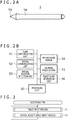
- FIG. 2A is a perspective view of the external appearance of the electronic pen 5.
- the electronic pen 5 includes a cylindrical external housing 5a.
- the external housing 5a accommodates a pen tip 5b (position indicating portion) for indicating a position in the input surface 4a of the plane position sensor 4. It is noted that although a gripping force sensor 55 described later and various members included in various switches are attached to a surface of the actual electronic pen 5, drawing of these members is omitted in FIG. 2A .
- the user When the user performs an input using the tablet input function, the user holds the external housing 5a with one hand and brings the pen tip 5b into contact with the input surface 4a of the plane position sensor 4. Subsequently, the user moves the pen tip 5b on the input surface 4a while maintaining the contact. In this manner, the user performs the input operation with the electronic pen 5.
- the user when the user performs an input using the virtual reality space input function, the user holds the external housing 5a with one hand and moves the electronic pen 5 in the air. In this manner, the user performs the input operation with the electronic pen 5.
- the input using the virtual reality space input function includes an input to the virtual tablet described above.
- FIG. 2B is a schematic block diagram illustrating functional blocks of the electronic pen 5.
- the electronic pen 5 includes a processing unit 50, a plane communication unit 51, a spatial communication unit 52, a spatial position detection unit 53, a pen pressure sensor 54, the gripping force sensor 55 (pressure sensor), and a force sense generation unit 56. It is noted that the electronic pen 5 may include only one of the pen pressure sensor 54 and the gripping force sensor 55, and the following description also includes such a case.
- the processing unit 50 includes a processor that is connected to each of the other units in the electronic pen 5 and controls these units while performing various processes described later.
- the processing unit 50 reads and executes a program stored in an internal memory, not illustrated, to control each of the other units in the electronic pen 5 and perform various processes described later.
- the plane communication unit 51 is a functional unit that transmits and receives signals to and from the computer 2 via the plane position sensor 4 under the control of the processing unit 50.
- the plurality of electrodes arranged in the input surface 4a of the plane position sensor 4 and a pen tip electrode (not illustrated) provided in the vicinity of the pen tip 5b of the electronic pen 5 are used as antennas.
- this transmission/reception includes a case where signals are unidirectionally transmitted from the electronic pen 5 to the plane position sensor 4 and a case where signals are bidirectionally transmitted and received between the electronic pen 5 and the plane position sensor 4. The following description continues on the assumption of the latter case.
- a signal transmitted from the plane position sensor 4 to the electronic pen 5 will be referred to as a "beacon signal” while a signal transmitted from the electronic pen 5 to the plane position sensor 4 will be referred to as a "pen signal.”
- a signal transmitted from the electronic pen 5 to the plane position sensor 4 will be referred to as a "pen signal.”
- an electromagnetic induction method or an active capacitive method can be used as a concrete method of the signal transmission/reception for this case.
- the beacon signal is a signal transmitted by the computer 2 at predetermined time intervals, for example, and includes a command for controlling the electronic pen 5 from the computer 2.
- the pen signal includes a burst signal (plane position information for indicating the position of the pen tip 5b in the input surface 4a) and a data signal.
- the burst signal is an unmodulated carrier wave.
- the data signal is obtained by modulating a carrier wave using data requested to be transmitted by the command.
- the spatial communication unit 52 has a function of transmitting and receiving signals to and from the computer 2 via the virtual reality display 3 under the control of the processing unit 50. These signals are transmitted and received by wire or wirelessly as described above.
- the plane position sensor 4 does not intervene in transmission and reception of the signals between the spatial communication unit 52 and the computer 2.
- the spatial position detection unit 53 is a functional unit including the spatial position sensor 8c illustrated in FIG. 1 and plays a role of detecting the above-described light reception level information (spatial position information for indicating the position of the electronic pen 5 in the space) through interaction with external devices (specifically, the position detection devices 7a and 7b). Specifically, the spatial position detection unit 53 performs processes of periodically or continuously performing an operation of detecting laser signals transmitted by the position detection devices 7a and 7b, generating light reception level information corresponding to the detected laser signals, and supplying the light reception level information to the processing unit 50 each time.
- the pen pressure sensor 54 is a sensor capable of detecting a force (pen pressure) applied to the pen tip 5b and includes, for example, a capacitance sensor (not illustrated) whose capacitance value changes according to the pen pressure.
- the processing unit 50 has functions of acquiring the pen pressure detected by the pen pressure sensor 54 and generating pen pressure information regarding the acquired pen pressure.
- the pen pressure information is, for example, a digital value obtained by performing analog-digital conversion on the pen pressure that is analog information.
- the processing unit 50 has functions of acquiring the gripping force detected by the gripping force sensor 55 and generating pressure information regarding the acquired gripping force.
- the pressure information is, for example, a digital value obtained by performing analog-digital conversion on the gripping force that is analog information.
- the force sense generation unit 56 has a function of generating a force sense according to a control signal supplied from the computer 2.
- the force sense here is, for example, the vibration of the external housing 5a.
- the computer 2 supplies the control signal to the electronic pen 5 via the spatial communication unit 52. This causes the force sense generation unit 56 to generate a force sense. Accordingly, the user can gain a feeling that the pen tip 5b collides with the surface of the virtual tablet that does not exist in reality.
- the processing unit 50 When an input is performed using the tablet input function, the processing unit 50 first performs an operation of detecting a beacon signal transmitted from the computer 2 via the plane communication unit 51. As a result, when the beacon signal has been detected, the processing unit 50 sequentially outputs the above-described burst signal and data signal to the plane communication unit 51 as a response to the beacon signal.
- the data signal output in this manner can include the above-described pen pressure information or pressure information.
- the plane communication unit 51 transmits the burst signal and the data signal input in this manner to the computer 2 via the plane position sensor 4.
- the computer 2 When the computer 2 receives the burst signal via the plane position sensor 4, the computer 2 detects a plane position indicating the position of the pen tip 5b in the input surface 4a based on the reception intensity of the burst signal in each of the plurality of electrodes arranged in the input surface 4a. Further, the computer 2 acquires data transmitted by the electronic pen 5 by receiving the data signal using the electrode closest to the detected plane position among the plurality of electrodes arranged in the input surface 4a. Then, the computer 2 performs 2D drawing based on the detected plane position and the received data. Details of 2D drawing will be described later. The tablet input function is realized in this manner.
- the processing unit 50 sequentially outputs the light reception level information supplied from the spatial position detection unit 53 to the spatial communication unit 52. Further, the processing unit 50 also outputs the pen pressure information or the pressure information generated as described above to the spatial communication unit 52, together with the light reception level information.
- the spatial communication unit 52 transmits each information input in this manner to the computer 2.
- the computer 2 When the computer 2 receives each information described above from the spatial communication unit 52, the computer 2 detects a spatial position indicating the position of the electronic pen 5 in the space based on the received light reception level information.
- information indicating the shape of the electronic pen 5 and a relative positional relation between the spatial position detection unit 53 and the pen tip 5b may be stored in the computer 2 in advance, and the computer 2 may convert the position obtained directly from the light reception level information into the position of the pen tip 5b based on this information and detect the position obtained by the conversion as a spatial position.
- the computer 2 performs 3D drawing based on the detected spatial position and the received pen pressure information or pressure information. Details of 3D drawing will also be described later.
- the virtual reality space input function is realized in this manner.
- FIG. 3 is a processing flow diagram illustrating processing performed by the processing unit 50 of the electronic pen 5.
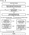
- FIG. 4 is a processing flow diagram illustrating details of a tablet input process (step S1) illustrated in FIG. 3 .
- FIG. 5 is a processing flow diagram illustrating details of a virtual reality space input process (step S2) illustrated in FIG. 3 .
- the operation of the electronic pen 5 will be described in detail with reference to these FIGs. 3 to 5 .
- the processing unit 50 performs the tablet input process (step S1) and the virtual reality space input process (step S2) in a time division manner.
- the processing unit 50 which performs the tablet input process, first performs an operation of detecting a beacon signal using the plane communication unit 51 (steps S10 and S11).
- the plane communication unit 51 attempts to detect a beacon signal by demodulating a signal that has reached the pen tip electrode described above.
- the processing unit 50 ends the tablet input process.
- the processing unit 50 outputs a burst signal to the plane communication unit 51, causing the plane communication unit 51 to transmit the burst signal (step S12).
- the subsequent process differs depending on whether or not the electronic pen 5 includes the pen pressure sensor 54.
- the processing unit 50 acquires a pen pressure from the output of the pen pressure sensor 54 (step S13), and transmits, from the plane communication unit 51, a data signal including pen pressure information regarding the acquired pen pressure (step S14).
- the processing unit 50 acquires a gripping force from the output of the gripping force sensor 55 (step S15), and transmits, from the plane communication unit 51, a data signal including pressure information regarding the acquired gripping force (step S16).
- the processing unit 50 ends the tablet input process and starts the next virtual reality space input process (step S2), as can be understood from FIG. 3 .
- the processing unit 50 which performs the virtual reality space input process, first performs an operation of detecting laser signals using the spatial position detection unit 53 (steps S20 and S21). As a result, when no laser signal has been detected, the processing unit 50 ends the virtual reality space input process. By contrast, when laser signals have been detected, the processing unit 50 acquires light reception level information corresponding to the laser signals from the spatial position detection unit 53 and causes the spatial communication unit 52 to transmit the light reception level information (step S22).
- the subsequent process differs depending on whether or not the electronic pen 5 includes the pen pressure sensor 54.
- the processing unit 50 acquires a gripping force from the output of the gripping force sensor 55 (step S26), and transmits, from the spatial communication unit 52, pressure information regarding the acquired gripping force (step S27).
- the processing unit 50 acquires a pen pressure from the output of the pen pressure sensor 54 (step S23) and determines whether or not the acquired pen pressure exceeds a predetermined value (step S24). This determination is to determine whether or not the pen tip 5b is in contact with an actual surface and is performed so as not to use the pen pressure when the pen tip 5b is not in contact therewith.
- the actual surface here corresponds to a surface such as a simple plate. Accordingly, for example, arranging the actual plate so as to match the display position of the virtual tablet makes it possible to use the pen pressure sensor 54 for the virtual tablet.
- step S24 When it is determined in step S24 that the pen pressure exceeds the predetermined value, the processing unit 50 transmits, from the spatial communication unit 52, pen pressure information regarding the acquired pen pressure (step S25). On the other hand, when it is determined in step S24 that the pen pressure does not exceed the predetermined value, the processing unit 50 advances the process to step S26 and transmits the pressure information (steps S26 and S27). After the transmission in step S25 or step S27, the processing unit 50 ends the virtual reality space input process and starts the next tablet input process (step S1), as can be understood from FIG. 3 .
- FIG. 6 is a processing flow diagram illustrating processing performed by the control unit 2a of the computer 2. Further, FIG. 7 is a processing flow diagram illustrating details of a correlation acquisition process (step S30) illustrated in FIG. 6 . FIG. 10 is a processing flow diagram illustrating details of a tablet drawing process (step S35) illustrated in FIG. 6 . FIG. 11 is a processing flow diagram illustrating details of a virtual reality space drawing process (step S41) illustrated in FIG. 6 .
- the operation of the computer 2 will be described in detail with reference to these figures.
- control unit 2a first performs the correlation acquisition process (step S30).
- the correlation acquisition process is a process of acquiring a correlation f between a pen pressure detected by the pen pressure sensor 54 and a gripping force detected by the gripping force sensor 55.
- the control unit 2a first causes the electronic pen 5 to perform a pen pressure detection operation by the pen pressure sensor 54 and a gripping force detection operation by the gripping force sensor 55 at the same time over a predetermined number of times, and receives pen pressure information and pressure information from the electronic pen 5 each time (steps S50 to S52).
- the control unit 2a After repeating the predetermined number of times, acquires the correlation f between the pen pressure and the gripping force based on multiple combinations of the pen pressure and the gripping force that have been acquired (step S53) and ends the correlation acquisition process.
- the correlation f acquired in this manner is, for example, a correlation function representing a correlation between the pen pressure and the gripping force.
- FIGs 8A and 8B are diagrams for describing the correlation f between a pen pressure and a gripping force.
- P represents a pen pressure
- G represents a gripping force
- F represents a frictional force between the user's hand and the surface of the electronic pen 5.
- the control unit 2a which has completed the correlation acquisition process, subsequently sets a drawing region in the virtual reality space (step S31).
- the drawing region is a region in which 3D drawing is performed by the electronic pen 5.
- FIGs. 9A and 9B are diagrams each illustrating a specific example of the drawing region.
- FIG. 9A illustrates an example in which a region within a predetermined distance from a display surface of a virtual tablet B is set as a drawing region A.
- the drawing region A according to this example is a region in which an input to the virtual tablet B is possible.
- the control unit 2a performs 3D drawing after replacing the detected spatial position with a spatial position obtained by projecting the detected spatial position on the display surface of the virtual tablet B during the virtual reality space drawing process illustrated in step S35 described later. This allows the user to draw a plane figure on the display surface of the virtual tablet B.
- the above-described predetermined distance is preferably set to a value greater than 0. This is because when the user attempts to make an input to the display surface of the virtual tablet B with the electronic pen 5, it is difficult to keep the electronic pen 5 in contact with the display surface that does not physically exist.
- FIG. 9B illustrates an example in which any three-dimensional space is set as the drawing region A.
- the control unit 2a performs 3D drawing without performing the replacement as in the example of FIG. 9A . This allows the user to draw a three-dimensional figure in the drawing region A.
- the control unit 2a subsequently performs an operation of detecting light reception level information and a burst signal (step S32). Specifically, this process includes a process of receiving light reception level information from the electronic pen 5 by wire or wirelessly and a process of receiving a burst signal from the electronic pen 5 via the plane position sensor 4.
- the control unit 2a performs step S32, and when, as a result, the burst signal has been detected (determination is positive in step S33), the control unit 2a advances the process to step S34. When the burst signal has not been detected (determination is negative in step S33), the control unit 2a advances the process to step S36.
- the control unit 2a which has advanced the process to step S34, detects the above-described plane position (the position of the pen tip 5b in the input surface 4a) based on the detected burst signal (step S34). After that, for example, the control unit 2a performs the tablet drawing process for performing 2D drawing on the display of the tablet terminal including the plane position sensor 4 (step S35).
- the control unit 2a first performs an operation of detecting a data signal transmitted by the electronic pen 5 via the plane position sensor 4 (step S60). Then, the control unit 2a determines which of the pen pressure information and the pressure information is included in the data signal (step S61).
- the control unit 2a further determines whether or not the pen pressure indicated by the pen pressure information is equal to or less than a predetermined normal ON load (e.g., 0) (step S68). As a result, when the pen pressure is determined to be equal to or less than the normal ON load, the control unit 2a ends the process without performing 2D drawing. This is a process when it is considered that the pen tip 5b of the electronic pen 5 is not in contact with the input surface 4a (what is generally called hover state).
- a predetermined normal ON load e.g., 0
- control unit 2a performs 2D drawing on the display of the tablet terminal that is the plane position sensor 4, for example, based on the plane position detected in step S34 and the pen pressure indicated by the pen pressure information (step S69).
- the 2D drawing performed in step S69 will be specifically described here.
- the 2D drawing includes a rendering process and a display process.
- the control unit 2a arranges a circle having a radius matching the corresponding pen pressure at each of a series of plane positions that are sequentially detected. Then, smoothly connecting the circumferences of the respective circles generates two-dimensional curve data (ink data) having a width corresponding to the pen pressure.
- the display process is a process of displaying the curve data generated in this manner on the display of the tablet terminal that is the plane position sensor 4, for example.
- the control unit 2a When the pressure information is determined to be included in step S61, the control unit 2a performs a process for converting the gripping force indicated by the pressure information into a pen pressure (steps S62 to S67). Specifically, the control unit 2a first determines whether a reset flag A is true or false (step S62).
- the reset flag A is a flag that indicates whether or not the electronic pen 5 has just entered a range in which the burst signal reaches the plane position sensor 4. When the electronic pen 5 has just entered the range, the determination result in step S62 is false.
- the control unit 2a which has made the false determination in step S62, further determines whether or not the gripping force indicated by the pressure information is equal to or greater than a predetermined value (step S63). Then, when the gripping force is determined to be less than the predetermined value, the gripping force indicated by the pressure information is set as an initial gripping force (step S64). When the gripping force is determined to be equal to or greater than the predetermined value, the predetermined value is set as the initial gripping force (step S65). It is noted that the initial gripping force is a variable that is used to treat the gripping force when the electronic pen 5 enters the range in which the burst signal reaches the plane position sensor 4 (at the time of pen down) as 0. Further, step S65 defines the upper limit of the initial gripping force and is used, for example, to prevent the gripping force necessary for increasing the line width from becoming too large, preventing the user from being unable to exert a sufficient pen pressure.
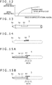
- FIG. 12 is a diagram for describing the meaning of the initial gripping force.
- the horizontal axis represents a force on the surface of the external housing 5a
- the vertical axis represents a gripping force detected by the gripping force sensor 55.
- the control unit 2a does not use the gripping force itself detected by the gripping force sensor 55 but uses a value obtained by subtracting the initial gripping force from the gripping force.
- the user can input a pen pressure using the gripping force by increasing or decreasing the gripping force with the gripping force at the time of pen down as a reference.
- step S64 when the control unit 2a performs step S64 or step S65, the control unit 2a sets the reset flag A to true (step S66). After that, the control unit 2a performs the process of converting the gripping force into a pen pressure using the correlation f (step S67). The step S67 is also performed when true determination is made in step S62. In step S67, the control unit 2a substitutes a value obtained by subtracting the initial gripping force from the gripping force indicated by the pressure information into the correlation f as a gripping force. Accordingly, as described with reference to FIG. 12 , the user can input a pen pressure using the gripping force by increasing or decreasing the gripping force with the gripping force at the time of pen down as a reference.
- the control unit 2a which has obtained the pen pressure in step S67, performs steps S68 and S69 using this pen pressure. These steps realize 2D drawing similar to the case where the pen pressure information is included in the data signal.
- the control unit 2a which has performed step S69, ends the tablet drawing process. Then, the control unit 2a returns to step S32 of FIG. 6 to perform the operation of detecting the next light reception level information and burst signal.
- the control unit 2a which has advanced the process to step S36 of FIG. 6 , first sets the reset flag A to false (step S36). This makes it possible to return the reset flag A to false when the electronic pen 5 is moved out of the range in which the burst signal reaches the plane position sensor 4.
- control unit 2a determines whether or not light reception level information has been detected by the detection operation in step S32 (step S37). Then, when the light reception level information is determined to have been detected, the control unit 2a detects the above-described spatial position (the position of the electronic pen 5 (or its pen tip 5b) in the space) based on the detected light reception level information (step S38). Subsequently, the control unit 2a determines whether or not the detected spatial position is the position within the drawing region set in step S31 (step S39).
- the control unit 2a which has determined in step S39 that the detected spatial position is the position within the drawing region, performs the virtual reality space drawing process for performing 3D drawing in the virtual reality space (step S41).
- the process of replacing the detected spatial position with a spatial position obtained by projecting the detected spatial position on the display surface of the virtual tablet may be inserted between step S39 and step S41 (step S40).
- the step S40 is a process that can be performed only when the drawing region including the detected spatial position is a region set on the display surface of the virtual tablet B as illustrated in FIG. 9A . This allows the user to draw a plane figure on the display surface of the virtual tablet, as described above.
- control unit 2a first performs an operation of receiving pen pressure information or pressure information (step S70). Then, the control unit 2a determines which of the pen pressure information and the pressure information has been received (step S71).
- the control unit 2a further determines whether or not the pen pressure indicated by the pen pressure information is equal to or less than the predetermined normal ON load (e.g., 0) (step S80). As a result, when the pen pressure is determined to be equal to or less than the normal ON load, the control unit 2a ends the process without performing 3D drawing. This is a process when it is considered that the pen tip 5b of the electronic pen 5 is not in contact with the above-described actual plate (for example, the one that is arranged so as to match the display position of the virtual tablet).
- the predetermined normal ON load e.g., 0
- control unit 2a performs 3D drawing in the virtual reality space based on the spatial position detected in step S38 (or the spatial position acquired in step S40) and the pen pressure indicated by the pen pressure information (step S81).
- the 3D drawing performed in step S79 also includes a rendering process and a display process.
- the rendering process the control unit 2a arranges a sphere having a radius matching the corresponding pen pressure at each of a series of spatial positions that are sequentially detected. Then, smoothly connecting the surfaces of the respective spheres generates three-dimensional curve data having a cross-sectional diameter corresponding to the pen pressure.
- the display process is a process of displaying the curve data generated in this manner in the virtual reality space. It is noted that when the control unit 2a fixes the spatial position to a position in the display surface of the virtual tablet by performing step S40, the control unit 2a may perform 2D drawing in the display surface, instead of 3D drawing.
- step S71 the control unit 2a performs a process for converting the gripping force indicated by the pressure information into a pen pressure (steps S72 to S77).
- step S72 to S77 the pen pressure as the result of the conversion is acquired.
- a reset flag B is used instead of the reset flag A.
- the reset flag B is a flag that indicates whether or not the electronic pen 5 has just entered the drawing region. When the electronic pen 5 has just entered the drawing region, the determination result in step S72 is false.
- the control unit 2a which has obtained the pen pressure in step S77, performs steps S78 and S79 using this pen pressure.
- steps S78 and S79 are processes similar to steps S80 and S81, except that instead of the normal ON load, the control unit 2a uses a value different from the normal ON load, preferably a space ON load that is set to a value greater than the normal ON load (that is, the control unit 2a determines in step S78 whether or not the pen pressure indicated by the pressure information is equal to or less than the predetermined space ON load (> normal ON load)).
- a gripping force increases as much as necessary to support the weight of the electronic pen 5 when the electronic pen 5 is operated while being floated in the air.
- the space ON load is used in step S78, instead of the normal ON load.
- the control unit 2a which has performed step S79, ends the virtual reality space drawing process. Then, the control unit 2a returns to step S32 of FIG. 6 to perform the operation of detecting the next light reception level information and burst signal.
- the control unit 2a determines in step S37 of FIG. 6 that the light reception level information has not been detected and when the control unit 2a determines in step S39 of FIG. 6 that the spatial position is not within the drawing region, the control unit 2a sets the reset flag B to false (step S42). After that, the control unit 2a returns to step S32 to perform the operation of detecting the next light reception level information and burst signal. Performing step S42 can return the reset flag B to false when the electronic pen 5 is moved out of the drawing region (including a case where the electronic pen 5 is moved out of the virtual reality space).
- the electronic pen 5 is capable of outputting pressure information regarding a gripping force
- the computer 2 is capable of performing 3D drawing and 2D drawing based on the pressure information regarding the gripping force.
- FIG. 13 is a diagram illustrating a structure of the gripping force sensor 55 according to a first example.
- the gripping force sensor 55 according to the present example includes a touch sensor capable of sensing a depressing force using a pressure-sensitive method, for example, and is provided on a side surface of the external housing 5a.
- the processing unit 50 for this case acquires the depressing force detected by the gripping force sensor 55 as a gripping force.
- FIG. 14 is a diagram illustrating a structure of the gripping force sensor 55 according to a second example.
- the gripping force sensor 55 according to the present example includes a button mechanism capable of detecting an amount of depression in a stepwise or continuous manner and is provided on the side surface of the external housing 5a.
- the processing unit 50 for this case acquires the amount of depression detected by the gripping force sensor 55 as a gripping force.
- Specific examples of the button mechanism include an actuator, a Hall effect device, a strain gauge, and the like.
- FIG. 15 depicts diagrams illustrating a structure of the gripping force sensor 55 according to a third example.
- the gripping force sensor 55 according to the present example also serves as the pen pressure sensor 54 and includes a capacitor having a structure in which a dielectric 11 is provided between two electrode plates 10 and 12.
- One end of a core body 13 is included in the pen tip 5b while another end of the core body 13 is connected to the electrode plate 10.
- the electrode plate 12 is connected to a button mechanism 14, which is provided on the side surface of the external housing 5a.
- the capacitor according to the present example is configured such that the distance between the electrode plate 10 and the electrode plate 12 changes according to a force applied to the pen tip 5b and, as a result, the capacitance also changes. Further, the capacitor according to the present example is configured such that, as can be understood by comparing FIG. 15A with FIG. 15B , the electrode plate 12 moves laterally according to an amount of depression of the button mechanism 14 and as a result, the capacitance changes.
- the processing unit 50 according to the present example regards the capacitor according to the present example as the pen pressure sensor 54 and acquires a pen pressure from the capacitance thereof.
- the processing unit 50 regards the capacitor according to the present example as the gripping force sensor 55 and acquires a gripping force from the capacitance thereof.
- both the gripping force sensor 55 and the pen pressure sensor 54 can be implemented by one capacitor.
- a load cell can also serve as both the gripping force sensor 55 and the pen pressure sensor 54. Since the load cell can measure a stress in each of an X direction, a Y direction, and a Z direction individually, a pen pressure that is a force in the pen axis direction and a gripping force that is a force perpendicular to the pen axis direction can be individually measured based on the measured individual stresses.
- FIG. 16 is a diagram illustrating a structure of the gripping force sensor 55 according to a fourth example.
- the gripping force sensor 55 according to the present example has a structure in which a pressure-sensitive sensor 15, a substrate 16, and a dome button 17 are stacked, and is provided on the side surface of the external housing 5a such that the surface on the dome button 17 side is exposed.
- the pressure-sensitive sensor 15 is a sensor capable of sensing a depressing force applied to the surface of the external housing 5a.
- the dome button 17 is a button mechanism capable of being turned on and off by the user.
- FIG. 17 depicts processing flow diagrams illustrating processing performed by the processing unit 50 of the electronic pen 5 when the gripping force sensor 55 according to the fourth example is used.
- FIG. 17A is a processing flow diagram in which steps S90 to S95 are added to the processing flow diagram illustrated in FIG. 3 .
- FIG. 17B is a processing flow diagram in which step S96 is added to the processing flow diagram illustrated in FIG. 4 or 5 .
- an operation of the electronic pen 5 including the gripping force sensor 55 according to the fourth example will be described with reference to FIG. 17 .
- the processing unit 50 first determines whether the dome button 17 is on or off (step S90). As a result, when the dome button 17 is determined to be off, the processing unit 50 sets a reset flag C to false (step S95) and starts the tablet input process of step S1.
- the reset flag C is a flag that indicates whether or not the dome button 17 has been just pressed. When the dome button 17 has been just pressed, the determination result in step S91 described later is false.
- the processing unit 50 determines whether the reset flag C is true or false (step S91).
- the processing unit 50 which has determined that the reset flag C is true here, starts the tablet input process of step S1 immediately.
- the processing unit 50 acquires a gripping force from the gripping force sensor 55 (step S92) and sets the acquired gripping force as an initial gripping force (step S93).
- the initial gripping force here is a variable used for treating the gripping force when the dome button 17 is pressed as 0, and is independent of the initial gripping force used in the computer 2 (the one used in the processing flow illustrated in FIG. 10 or 11 ).
- the processing unit 50 which has performed step S93, sets the reset flag C to true (step S94) and starts the tablet input process of step S1.
- the processing unit 50 uses a gripping force obtained by subtracting the initial gripping force from each of the gripping force acquired in step S15 of FIG. 4 and the gripping force acquired in step S26 of FIG. 5 as a gripping force (step S96). That is, the processing unit 50 transmits, to the computer 2, pressure information regarding the gripping force obtained by subtraction in step S96, not the gripping force itself acquired in the corresponding step S15 or S26.
- the user of the electronic pen 5 can input a pen pressure using a gripping force by increasing or decreasing the gripping force with a gripping force at the timing when the user turns on the dome button 17 on the user's own will as a reference.
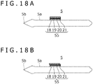
- FIG. 18 depicts diagrams illustrating a structure of the gripping force sensor 55 according to a fifth example.
- the gripping force sensor 55 according to the present example includes a capacitor and is provided on the side surface of the external housing 5a.
- the capacitor has a structure in which a dielectric 19 and a rubber 20 are provided between two electrode plates 18 and 21.
- the processing unit 50 according to the present example acquires the capacitance of the capacitor, which is the gripping force sensor 55, as a gripping force.
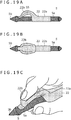
- FIG. 19 depicts diagrams illustrating a structure of the gripping force sensor 55 according to a sixth example.
- the electronic pen 5 according to the present example includes a grip member 22, which is attached to the external housing 5a.
- the gripping force sensor 55 according to the present example is incorporated in the grip member 22.
- FIG. 19A illustrates the side surface of the electronic pen 5 with the grip member 22 attached.
- FIG. 19B illustrates an upper surface of the electronic pen 5 with the grip member 22 attached.
- FIG. 19C illustrates the electronic pen 5 being used with the grip member 22 attached.
- the grip member 22 includes a cylindrical base 22a and a finger rest 22b.
- the base 22a is engaged with the external housing 5a.
- the finger rest 22b extends in an arch shape from one end of the base 22a.
- the user uses the electronic pen 5 with the index finger placed on the finger rest 22b.
- FIG. 19 illustrates an example in which the grip member 22 is a separate body from the external housing 5a, the grip member 22 and the external housing 5a may be integrally formed.
- the gripping force sensor 55 is, for example, a strain gauge embedded in the finger rest 22b and is capable of detecting a force in the index finger of the user (a depressing force of the finger rest 22b).
- the processing unit 50 acquires the force detected in this manner as a gripping force.
- incorporating an acceleration sensor in the electronic pen 5 or the grip member 22 allows the processing unit 50 to detect a user's operation of shaking the electronic pen 5. By combining this with the detection of a depressing force of the finger rest 22b using the gripping force sensor 55, an operation of tapping the touch surface can be simulated.
Landscapes
- Engineering & Computer Science (AREA)
- General Engineering & Computer Science (AREA)
- Theoretical Computer Science (AREA)
- Human Computer Interaction (AREA)
- Physics & Mathematics (AREA)
- General Physics & Mathematics (AREA)
- Position Input By Displaying (AREA)
- User Interface Of Digital Computer (AREA)
Abstract
Description
- The present invention relates to a position indicating device and an information processing device, and particularly, to a pen-type position indicating device in use for indicating both a position in a touch surface and a position in a space, and an information processing device that is connected to such a position indicating device.
- In recent years, a pen-type position indicating device (hereinafter referred to as an "electronic pen") that is used in combination with a tablet-type computer has attracted attention. This type of electronic pen is usually provided with a pen pressure sensor that detects a pressure (pen pressure) applied to a pen tip. When the computer detects the position of the electronic pen in a touch surface, the computer receives a pen pressure value from the electronic pen. Then, when the computer draws a line image according to the detected position, the computer controls a line width and transparency of the line image according to the received pen pressure value. This configuration can produce the feel of writing similar to that of an existing pen that ejects ink, for example, draw a thicker line as the force with which the pen tip is pressed against the touch surface is greater.
- Further,
Patent Document 1 discloses a pen-type input device that does not require a touch surface. This pen-type input device includes a pressure sensor on its side surface and is capable of detecting a gripping force of the user. According to the view ofPatent Document 1, when the user draws a character or a figure by holding a pen, a characteristic corresponding to the character or the figure to be drawn appears in a change in the gripping force. The technique ofPatent Document 1 recognizes this characteristic as the character or the figure, thereby enabling an input of the character or the figure without detecting the position of a pen tip in the touch surface. - Patent Document 1: Japanese Patent Laid-Open No.
Hei 8-6710 - Incidentally, the inventors of the present application consider how to make it possible to write a character and draw a picture on a virtual plane in a virtual reality (including VR: Virtual Reality, AR: Augmented Reality, and MR: Mixed Reality) space using the electronic pen described above. In this case, since there is no actual touch surface, the pen pressure value cannot be detected by the above-described pen pressure sensor. Without the pen pressure value, it is not possible to control the line width and the transparency according to the pen pressure value, and therefore, it is not possible to produce the feel of writing similar to that of an existing pen. Accordingly, there has been a need for another method that can control the line width and the transparency in a preferable manner.
- Therefore, one of objects of the present invention is to provide a position indicating device and an information processing device capable of controlling the line width and the transparency in a preferable manner even when there is no actual touch surface.
- A position indicating device according to the present invention includes a housing, a position indicating portion configured to indicate a position, a first sensor configured to detect a first pressure applied to the position indicating portion, a second sensor configured to detect a second pressure applied to the housing, a first communication unit configured to transmit the first pressure detected by the first sensor, and a second communication unit configured to transmit the second pressure detected by the second sensor.
- It is noted that the position indicating device according to the present invention may be a position indicating device including a cylindrical external housing accommodating a position indicating portion for indicating a position in an input surface of a plane position sensor, a spatial position detection unit configured to detect spatial position information for indicating a position of the position indicating device in a space through interaction with an external device, a pressure sensor configured to detect a force on the external housing, and a processing unit configured to output the spatial position information detected by the spatial position detection unit, plane position information for indicating the position of the position indicating portion in the input surface, and pressure information regarding the force detected by the pressure sensor.
- An information processing device according to the present invention is capable of communicating with a position indicating device including a housing, a position indicating portion configured to indicate a position, and a pressure sensor configured to detect a force applied to the housing. The information processing device includes a communication unit configured to receive a pressure detected by the pressure sensor, and a controller configured to control generation of a 3D (Three-Dimensional) object in a virtual reality space based on a position of the position indicating device in a space and the pressure received by the communication unit.
- It is noted that the information processing device according to the present invention may be a computer that is configured to be connected to a position indicating device including a cylindrical external housing accommodating a position indicating portion configured to indicate a position in an input surface of a plane position sensor, and a pressure sensor configured to detect a force applied to a surface of the external housing, that is configured to receive, from the position indicating device, spatial position information for indicating a position of the position indicating device in a space, plane position information for indicating the position of the position indicating portion in the input surface, and pressure information regarding the force detected by the pressure sensor, that is configured to, when the spatial position information and the pressure information have been received, detect a spatial position indicating the position of the position indicating device in the space based on the received spatial position information and perform 3D drawing based on the detected spatial position and the received pressure information, and that is configured to, when the plane position information and the pressure information have been received, detect a plane position indicating the position of the position indicating portion in the touch surface based on the received plane position information and perform 2D (Two-Dimensional) drawing based on the detected plane position and the received pressure information.
- When the user writes a character or draws a picture on a virtual plane, a force (=gripping force) detected by a pressure sensor has a certain correlation relation with a pen pressure detected when the user writes a character or draws a picture on an actual touch surface. Therefore, the position indicating device according to the present invention capable of transmitting a pressure detected by a pressure sensor and the information processing device according to the present invention capable of performing 3D drawing based on the pressure detected by the pressure sensor can control the line width and the transparency in a preferable manner even when there is no actual touch surface.
-
- [
FIG. 1 ]
FIG. 1 is a diagram illustrating a configuration of a spatialposition indicating system 1 according to a first embodiment of the present invention. - [
FIG. 2 ]
FIG. 2A is a perspective view of an external appearance of anelectronic pen 5, whileFIG. 2B is a schematic block diagram illustrating functional blocks of theelectronic pen 5. - [
FIG. 3 ]
FIG. 3 is a processing flow diagram illustrating processing performed by aprocessing unit 50 of theelectronic pen 5. - [
FIG. 4 ]
FIG. 4 is a processing flow diagram illustrating details of a tablet input process illustrated inFIG. 3 . - [
FIG. 5 ]
FIG. 5 is a processing flow diagram illustrating details of a virtual reality space input process illustrated inFIG. 3 . - [
FIG. 6 ]
FIG. 6 is a processing flow diagram illustrating processing performed by acontrol unit 2a of acomputer 2. - [
FIG. 7 ]
FIG. 7 is a processing flow diagram illustrating details of a correlation acquisition process (step S30) illustrated inFIG. 6 . - [
FIG. 8 ]
FIG. 8 depicts diagrams for describing a correlation f between a pen pressure and a gripping force. - [
FIG. 9 ]
FIGs. 9A and 9B are diagrams each illustrating a specific example of a drawing region. - [
FIG. 10 ]
FIG. 10 is a processing flow diagram illustrating details of a tablet drawing process illustrated inFIG. 6 . - [
FIG. 11 ]
FIG. 11 is a processing flow diagram illustrating details of a virtual reality space drawing process illustrated inFIG. 6 . - [
FIG. 12 ]
FIG. 12 is a diagram for describing the meaning of an initial gripping force. - [
FIG. 13 ]
FIG. 13 is a diagram illustrating a structure of agripping force sensor 55 according to a first example. - [
FIG. 14 ]
FIG. 14 is a diagram illustrating a structure of thegripping force sensor 55 according to a second example. - [
FIG. 15 ]
FIG. 15 depicts diagrams illustrating a structure of thegripping force sensor 55 according to a third example. - [
FIG. 16 ]
FIG. 16 is a diagram illustrating a structure of thegripping force sensor 55 according to a fourth example. - [
FIG. 17 ]
FIG. 17 depicts processing flow diagrams illustrating processing performed by theprocessing unit 50 of theelectronic pen 5 when the grippingforce sensor 55 according to the fourth example is used. - [
FIG. 18 ]
FIG. 18 depicts diagrams illustrating a structure of thegripping force sensor 55 according to a fifth example. - [
FIG. 19 ]
FIG. 19 depicts diagrams illustrating a structure of thegripping force sensor 55 according to a sixth example. - Hereinafter, embodiments of the present invention will be described in detail with reference to the accompanying drawings.
-
FIG. 1 is a diagram illustrating a configuration of a spatialposition indicating system 1 according to an embodiment of the present invention. As illustrated in the figure, the spatialposition indicating system 1 according to the present embodiment includes acomputer 2, avirtual reality display 3, aplane position sensor 4, anelectronic pen 5,position detection devices spatial position sensors 8a to 8c. Thespatial position sensors 8a to 8c are provided in theplane position sensor 4, thevirtual reality display 3, and theelectronic pen 5, respectively. - In principle, each device illustrated in
FIG. 1 is provided in a room. In the spatialposition indicating system 1, almost the entire room can be used as a virtual reality space. - The
computer 2 includes acontrol unit 2a and amemory 2b. Each processing performed by thecomputer 2 described below is performed by thecontrol unit 2a reading and executing a program stored in thememory 2b. - The
computer 2 is connected to each of thevirtual reality display 3, theposition detection devices plane position sensor 4 by wire or wirelessly. In the case of wired communication, it is preferable to use a USB (Universal Serial Bus), for example. In the case of wireless communication, it is preferable to use a wireless LAN (Local Area Network) such as Wi-Fi (Wireless Fidelity) (registered trademark) or near-field communication such as Bluetooth (registered trademark), for example. It is noted that when theplane position sensor 4 and thevirtual reality display 3 have a function as a computer, this computer may constitute a part of or theentire computer 2. - The
computer 2 has a function of displaying a virtual reality space on thevirtual reality display 3. This virtual reality space may be a VR (Virtual Reality) space, an AR (Augmented Reality) space, or an MR (Mixed Reality) space. When the VR space is displayed, the user wearing thevirtual reality display 3 recognizes a virtual reality and is disconnected from the real world. By contrast, when the AR space or the MR space is displayed, the user wearing thevirtual reality display 3 recognizes a space in which the virtual reality and the real world are mixed. - The
computer 2 functions as a rendering device that renders various 3D objects in the virtual reality space set with the positions of theposition detection devices computer 2 also updates the display of thevirtual reality display 3 according to the result of the rendering. Accordingly, various 3D objects appear in the virtual reality space displayed on thevirtual reality display 3. Thecomputer 2 performs rendering based on 3D object information stored in thememory 2b. The 3D object information indicates the shape, position, and orientation of the corresponding 3D object in the virtual reality space indicating the virtual reality space set by thecomputer 2 and is stored in thememory 2b for each 3D object to be rendered. - The 3D objects rendered by the
computer 2 include 3D objects such as theplane position sensor 4 and theelectronic pen 5 illustrated inFIG. 1 that also exist in reality (hereinafter referred to as "first 3D objects") and 3D objects such as a virtual tablet (not illustrated) that do not exist in reality (hereinafter referred to as "second 3D objects"). When rendering these 3D objects, thecomputer 2 first detects the position and orientation of thespatial position sensor 8b in the real space and acquires viewpoint information indicating the viewpoint of the user based on the result of the detection. - When rendering first 3D objects, the
computer 2 further detects the positions and orientations of the spatial position sensors (e.g., thespatial position sensors memory 2b. Then, thecomputer 2 renders the first 3D objects in the virtual reality space based on the stored positions and orientations, the above-described viewpoint information, and the shapes stored for the first 3D objects. In addition, for theelectronic pen 5 in particular, thecomputer 2 performs processes of detecting the position of thespatial position sensor 8c to detect an operation performed by the user in the virtual reality space, and based on the result, newly creating a second 3D object (that is, newly storing 3D object information in thememory 2b) or moving or updating a second 3D object that is already held (that is, updating 3D object information that is already stored in thememory 2b). - By contrast, when rendering a second 3D object, the
computer 2 renders the second 3D object in the virtual reality space based on the corresponding 3D object information stored in thememory 2b and the above-described viewpoint information. - The
virtual reality display 3 is a VR display (head-mounted display) that is worn on the head of a human when used. While there are various types of commercially available virtual reality displays such as "a transmissive type" or "a non-transmissive type" or "a glasses type" or "a hat type," any of these virtual reality displays can be used as thevirtual reality display 3. - The
virtual reality display 3 is connected to each of thespatial position sensors 8a and the electronic pen 5 (including thespatial position sensor 8c) by wire or wirelessly. Through this connection, each of thespatial position sensors virtual reality display 3 of light reception level information described later. Thevirtual reality display 3 notifies thecomputer 2 of the light reception level information notified by each of thespatial position sensors spatial position sensor 8b incorporated in thevirtual reality display 3. Thecomputer 2 detects the position and orientation of each of thespatial position sensors 8a to 8c in the real space based on the corresponding light reception level information notified in this manner. - The
plane position sensor 4 is a device including aninput surface 4a and a plurality of electrodes (not illustrated) arranged so as to cover theentire input surface 4a. Theinput surface 4a is preferably a flat surface and can be made of a material suitable for a pen tip of theelectronic pen 5 to slide thereon. The plurality of electrodes plays a role of detecting a pen signal (described later) transmitted by theelectronic pen 5. The pen signal detected by each electrode is supplied to thecomputer 2. Based on the supplied pen signal, thecomputer 2 acquires the position indicated by theelectronic pen 5 in theinput surface 4a and various kinds of data transmitted by theelectronic pen 5. Theplane position sensor 4 may be incorporated in a tablet terminal having a display function and a processor, for example. In this case, the processor of the tablet terminal can constitute a part of or theentire computer 2. - The
spatial position sensors 8a are fixedly installed on a surface of theplane position sensor 4. Therefore, the positions and orientations of thespatial position sensors 8a detected by thecomputer 2 indicate the position and orientation of theinput surface 4a in a virtual reality space coordinate system. - The
electronic pen 5 is a position indicating device having a pen shape. Theelectronic pen 5 has a function as an input device for the plane position sensor 4 (hereinafter referred to as a "tablet input function") and a function as an input device for the computer 2 (hereinafter referred to as a "virtual reality space input function"). The tablet input function includes a function of indicating a position in theinput surface 4a of theplane position sensor 4. Meanwhile, the virtual reality space input function includes a function of indicating a position in the virtual reality space. Details of each function will be described later. - The
position detection devices spatial position sensors 8a to 8c. Each of theposition detection devices computer 2. Each of thespatial position sensors 8a to 8c includes a plurality of light receiving sensors. The light receiving sensors receive laser signals emitted by the respectiveposition detection devices computer 2 via thevirtual reality display 3 as described above. It is noted that while, in the present embodiment, theposition detection devices -
FIG. 2A is a perspective view of the external appearance of theelectronic pen 5. As illustrated in the figure, theelectronic pen 5 includes a cylindricalexternal housing 5a. Theexternal housing 5a accommodates apen tip 5b (position indicating portion) for indicating a position in theinput surface 4a of theplane position sensor 4. It is noted that although agripping force sensor 55 described later and various members included in various switches are attached to a surface of the actualelectronic pen 5, drawing of these members is omitted inFIG. 2A . - When the user performs an input using the tablet input function, the user holds the
external housing 5a with one hand and brings thepen tip 5b into contact with theinput surface 4a of theplane position sensor 4. Subsequently, the user moves thepen tip 5b on theinput surface 4a while maintaining the contact. In this manner, the user performs the input operation with theelectronic pen 5. By contrast, when the user performs an input using the virtual reality space input function, the user holds theexternal housing 5a with one hand and moves theelectronic pen 5 in the air. In this manner, the user performs the input operation with theelectronic pen 5. The input using the virtual reality space input function includes an input to the virtual tablet described above. -
FIG. 2B is a schematic block diagram illustrating functional blocks of theelectronic pen 5. As illustrated in the figure, theelectronic pen 5 includes aprocessing unit 50, aplane communication unit 51, aspatial communication unit 52, a spatialposition detection unit 53, apen pressure sensor 54, the gripping force sensor 55 (pressure sensor), and a forcesense generation unit 56. It is noted that theelectronic pen 5 may include only one of thepen pressure sensor 54 and thegripping force sensor 55, and the following description also includes such a case. - The
processing unit 50 includes a processor that is connected to each of the other units in theelectronic pen 5 and controls these units while performing various processes described later. Theprocessing unit 50 reads and executes a program stored in an internal memory, not illustrated, to control each of the other units in theelectronic pen 5 and perform various processes described later. - The
plane communication unit 51 is a functional unit that transmits and receives signals to and from thecomputer 2 via theplane position sensor 4 under the control of theprocessing unit 50. In this transmission/reception, the plurality of electrodes arranged in theinput surface 4a of theplane position sensor 4 and a pen tip electrode (not illustrated) provided in the vicinity of thepen tip 5b of theelectronic pen 5 are used as antennas. Further, this transmission/reception includes a case where signals are unidirectionally transmitted from theelectronic pen 5 to theplane position sensor 4 and a case where signals are bidirectionally transmitted and received between theelectronic pen 5 and theplane position sensor 4. The following description continues on the assumption of the latter case. A signal transmitted from theplane position sensor 4 to theelectronic pen 5 will be referred to as a "beacon signal" while a signal transmitted from theelectronic pen 5 to theplane position sensor 4 will be referred to as a "pen signal." For example, an electromagnetic induction method or an active capacitive method can be used as a concrete method of the signal transmission/reception for this case. - The beacon signal is a signal transmitted by the
computer 2 at predetermined time intervals, for example, and includes a command for controlling theelectronic pen 5 from thecomputer 2. The pen signal includes a burst signal (plane position information for indicating the position of thepen tip 5b in theinput surface 4a) and a data signal. The burst signal is an unmodulated carrier wave. The data signal is obtained by modulating a carrier wave using data requested to be transmitted by the command. - The
spatial communication unit 52 has a function of transmitting and receiving signals to and from thecomputer 2 via thevirtual reality display 3 under the control of theprocessing unit 50. These signals are transmitted and received by wire or wirelessly as described above. Theplane position sensor 4 does not intervene in transmission and reception of the signals between thespatial communication unit 52 and thecomputer 2. - The spatial
position detection unit 53 is a functional unit including thespatial position sensor 8c illustrated inFIG. 1 and plays a role of detecting the above-described light reception level information (spatial position information for indicating the position of theelectronic pen 5 in the space) through interaction with external devices (specifically, theposition detection devices position detection unit 53 performs processes of periodically or continuously performing an operation of detecting laser signals transmitted by theposition detection devices processing unit 50 each time. - The
pen pressure sensor 54 is a sensor capable of detecting a force (pen pressure) applied to thepen tip 5b and includes, for example, a capacitance sensor (not illustrated) whose capacitance value changes according to the pen pressure. Theprocessing unit 50 has functions of acquiring the pen pressure detected by thepen pressure sensor 54 and generating pen pressure information regarding the acquired pen pressure. The pen pressure information is, for example, a digital value obtained by performing analog-digital conversion on the pen pressure that is analog information. - The gripping
force sensor 55 is a sensor capable of detecting a force (=a gripping force) on the surface of theexternal housing 5a of theelectronic pen 5. A specific configuration of thegripping force sensor 55 will be described later in detail with reference to the drawings. Theprocessing unit 50 has functions of acquiring the gripping force detected by the grippingforce sensor 55 and generating pressure information regarding the acquired gripping force. The pressure information is, for example, a digital value obtained by performing analog-digital conversion on the gripping force that is analog information. - The force
sense generation unit 56 has a function of generating a force sense according to a control signal supplied from thecomputer 2. The force sense here is, for example, the vibration of theexternal housing 5a. For example, when thepen tip 5b is in contact with a surface of the virtual tablet (more accurately, when thepen tip 5b is present within a predetermined distance from the surface of the virtual tablet), thecomputer 2 supplies the control signal to theelectronic pen 5 via thespatial communication unit 52. This causes the forcesense generation unit 56 to generate a force sense. Accordingly, the user can gain a feeling that thepen tip 5b collides with the surface of the virtual tablet that does not exist in reality. - When an input is performed using the tablet input function, the
processing unit 50 first performs an operation of detecting a beacon signal transmitted from thecomputer 2 via theplane communication unit 51. As a result, when the beacon signal has been detected, theprocessing unit 50 sequentially outputs the above-described burst signal and data signal to theplane communication unit 51 as a response to the beacon signal. The data signal output in this manner can include the above-described pen pressure information or pressure information. Theplane communication unit 51 transmits the burst signal and the data signal input in this manner to thecomputer 2 via theplane position sensor 4. - When the
computer 2 receives the burst signal via theplane position sensor 4, thecomputer 2 detects a plane position indicating the position of thepen tip 5b in theinput surface 4a based on the reception intensity of the burst signal in each of the plurality of electrodes arranged in theinput surface 4a. Further, thecomputer 2 acquires data transmitted by theelectronic pen 5 by receiving the data signal using the electrode closest to the detected plane position among the plurality of electrodes arranged in theinput surface 4a. Then, thecomputer 2 performs 2D drawing based on the detected plane position and the received data. Details of 2D drawing will be described later. The tablet input function is realized in this manner. - By contrast, when an input is performed using the virtual reality space input function, the
processing unit 50 sequentially outputs the light reception level information supplied from the spatialposition detection unit 53 to thespatial communication unit 52. Further, theprocessing unit 50 also outputs the pen pressure information or the pressure information generated as described above to thespatial communication unit 52, together with the light reception level information. Thespatial communication unit 52 transmits each information input in this manner to thecomputer 2. - When the
computer 2 receives each information described above from thespatial communication unit 52, thecomputer 2 detects a spatial position indicating the position of theelectronic pen 5 in the space based on the received light reception level information. In this case, information indicating the shape of theelectronic pen 5 and a relative positional relation between the spatialposition detection unit 53 and thepen tip 5b may be stored in thecomputer 2 in advance, and thecomputer 2 may convert the position obtained directly from the light reception level information into the position of thepen tip 5b based on this information and detect the position obtained by the conversion as a spatial position. Thecomputer 2 performs 3D drawing based on the detected spatial position and the received pen pressure information or pressure information. Details of 3D drawing will also be described later. The virtual reality space input function is realized in this manner. -
FIG. 3 is a processing flow diagram illustrating processing performed by theprocessing unit 50 of theelectronic pen 5. Further,FIG. 4 is a processing flow diagram illustrating details of a tablet input process (step S1) illustrated inFIG. 3 .FIG. 5 is a processing flow diagram illustrating details of a virtual reality space input process (step S2) illustrated inFIG. 3 . Hereinafter, the operation of theelectronic pen 5 will be described in detail with reference to theseFIGs. 3 to 5 . - First, as illustrated in
FIG. 3 , theprocessing unit 50 performs the tablet input process (step S1) and the virtual reality space input process (step S2) in a time division manner. - Next, referring to
FIG. 4 , theprocessing unit 50, which performs the tablet input process, first performs an operation of detecting a beacon signal using the plane communication unit 51 (steps S10 and S11). In this detection operation, theplane communication unit 51 attempts to detect a beacon signal by demodulating a signal that has reached the pen tip electrode described above. As a result, when the beacon signal has not been detected, theprocessing unit 50 ends the tablet input process. On the other hand, when the beacon signal has been detected, theprocessing unit 50 outputs a burst signal to theplane communication unit 51, causing theplane communication unit 51 to transmit the burst signal (step S12). - The subsequent process differs depending on whether or not the
electronic pen 5 includes thepen pressure sensor 54. In the former case, theprocessing unit 50 acquires a pen pressure from the output of the pen pressure sensor 54 (step S13), and transmits, from theplane communication unit 51, a data signal including pen pressure information regarding the acquired pen pressure (step S14). By contrast, in the latter case, theprocessing unit 50 acquires a gripping force from the output of the gripping force sensor 55 (step S15), and transmits, from theplane communication unit 51, a data signal including pressure information regarding the acquired gripping force (step S16). After the transmission in step S14 or step S16, theprocessing unit 50 ends the tablet input process and starts the next virtual reality space input process (step S2), as can be understood fromFIG. 3 . - Next, referring to
FIG. 5 , theprocessing unit 50, which performs the virtual reality space input process, first performs an operation of detecting laser signals using the spatial position detection unit 53 (steps S20 and S21). As a result, when no laser signal has been detected, theprocessing unit 50 ends the virtual reality space input process. By contrast, when laser signals have been detected, theprocessing unit 50 acquires light reception level information corresponding to the laser signals from the spatialposition detection unit 53 and causes thespatial communication unit 52 to transmit the light reception level information (step S22). - The subsequent process differs depending on whether or not the
electronic pen 5 includes thepen pressure sensor 54. In the latter case, theprocessing unit 50 acquires a gripping force from the output of the gripping force sensor 55 (step S26), and transmits, from thespatial communication unit 52, pressure information regarding the acquired gripping force (step S27). By contrast, in the former case, theprocessing unit 50 acquires a pen pressure from the output of the pen pressure sensor 54 (step S23) and determines whether or not the acquired pen pressure exceeds a predetermined value (step S24). This determination is to determine whether or not thepen tip 5b is in contact with an actual surface and is performed so as not to use the pen pressure when thepen tip 5b is not in contact therewith. It is noted that the actual surface here corresponds to a surface such as a simple plate. Accordingly, for example, arranging the actual plate so as to match the display position of the virtual tablet makes it possible to use thepen pressure sensor 54 for the virtual tablet. - When it is determined in step S24 that the pen pressure exceeds the predetermined value, the
processing unit 50 transmits, from thespatial communication unit 52, pen pressure information regarding the acquired pen pressure (step S25). On the other hand, when it is determined in step S24 that the pen pressure does not exceed the predetermined value, theprocessing unit 50 advances the process to step S26 and transmits the pressure information (steps S26 and S27). After the transmission in step S25 or step S27, theprocessing unit 50 ends the virtual reality space input process and starts the next tablet input process (step S1), as can be understood fromFIG. 3 . -
FIG. 6 is a processing flow diagram illustrating processing performed by thecontrol unit 2a of thecomputer 2. Further,FIG. 7 is a processing flow diagram illustrating details of a correlation acquisition process (step S30) illustrated inFIG. 6 .FIG. 10 is a processing flow diagram illustrating details of a tablet drawing process (step S35) illustrated inFIG. 6 .FIG. 11 is a processing flow diagram illustrating details of a virtual reality space drawing process (step S41) illustrated inFIG. 6 . Hereinafter, the operation of thecomputer 2 will be described in detail with reference to these figures. - As illustrated in
FIG. 6 , thecontrol unit 2a first performs the correlation acquisition process (step S30). - The correlation acquisition process is a process of acquiring a correlation f between a pen pressure detected by the
pen pressure sensor 54 and a gripping force detected by the grippingforce sensor 55. In this process, as illustrated inFIG. 7 , thecontrol unit 2a first causes theelectronic pen 5 to perform a pen pressure detection operation by thepen pressure sensor 54 and a gripping force detection operation by the grippingforce sensor 55 at the same time over a predetermined number of times, and receives pen pressure information and pressure information from theelectronic pen 5 each time (steps S50 to S52). - After repeating the predetermined number of times, the
control unit 2a acquires the correlation f between the pen pressure and the gripping force based on multiple combinations of the pen pressure and the gripping force that have been acquired (step S53) and ends the correlation acquisition process. The correlation f acquired in this manner is, for example, a correlation function representing a correlation between the pen pressure and the gripping force. In one example, the correlation f is expressed in the form of a pen pressure=f(gripping force). The following description continues on the assumption that the correlation f is used. -
FIGs 8A and 8B are diagrams for describing the correlation f between a pen pressure and a gripping force. In these figures, P represents a pen pressure, G represents a gripping force, and F represents a frictional force between the user's hand and the surface of theelectronic pen 5. - First, referring to
FIG. 8A , when the user attempts to draw a line while holding theelectronic pen 5 perpendicularly to theinput surface 4a, P≈F holds. Further, a relation of F≈µG holds between the gripping force G and the friction force F. It is noted that µ is a friction coefficient between the user's hand and the surface of theelectronic pen 5. Therefore, P≈µG holds. - Next, referring to
FIG. 8B , when the user attempts to draw a line while holding theelectronic pen 5 so as to incline theelectronic pen 5 by an angle θ relative to a normal direction of theinput surface 4a, F≈P'=Pcosθ holds. It is noted that P' is a component of force of the pen pressure P in a pen axis direction. Therefore, in this case, Pcosθ=µG holds from the relation of F≈µG described above. - The relation of Pcosθ=µG also includes the case illustrated in
FIG. 8A . Therefore, the correlation f can be universally expressed when f(G)=µG/cosθ holds. However, since the friction coefficient µ and the angle θ appearing therein are amounts that can vary from user to user, it is necessary to obtain a pen pressure=f(gripping force) for each user after all. Therefore, it is necessary to perform the correlation acquisition process as described with reference toFIG. 7 . - Returning to
FIG. 6 , thecontrol unit 2a, which has completed the correlation acquisition process, subsequently sets a drawing region in the virtual reality space (step S31). The drawing region is a region in which 3D drawing is performed by theelectronic pen 5. -
FIGs. 9A and 9B are diagrams each illustrating a specific example of the drawing region.FIG. 9A illustrates an example in which a region within a predetermined distance from a display surface of a virtual tablet B is set as a drawing region A. The drawing region A according to this example is a region in which an input to the virtual tablet B is possible. When a detected spatial position is within this type of drawing region A, thecontrol unit 2a performs 3D drawing after replacing the detected spatial position with a spatial position obtained by projecting the detected spatial position on the display surface of the virtual tablet B during the virtual reality space drawing process illustrated in step S35 described later. This allows the user to draw a plane figure on the display surface of the virtual tablet B. It is noted that the above-described predetermined distance is preferably set to a value greater than 0. This is because when the user attempts to make an input to the display surface of the virtual tablet B with theelectronic pen 5, it is difficult to keep theelectronic pen 5 in contact with the display surface that does not physically exist. -
FIG. 9B illustrates an example in which any three-dimensional space is set as the drawing region A. When a detected spatial position is within the drawing region A, thecontrol unit 2a performs 3D drawing without performing the replacement as in the example ofFIG. 9A . This allows the user to draw a three-dimensional figure in the drawing region A. - Returning to
FIG. 6 , thecontrol unit 2a subsequently performs an operation of detecting light reception level information and a burst signal (step S32). Specifically, this process includes a process of receiving light reception level information from theelectronic pen 5 by wire or wirelessly and a process of receiving a burst signal from theelectronic pen 5 via theplane position sensor 4. Thecontrol unit 2a performs step S32, and when, as a result, the burst signal has been detected (determination is positive in step S33), thecontrol unit 2a advances the process to step S34. When the burst signal has not been detected (determination is negative in step S33), thecontrol unit 2a advances the process to step S36. - The
control unit 2a, which has advanced the process to step S34, detects the above-described plane position (the position of thepen tip 5b in theinput surface 4a) based on the detected burst signal (step S34). After that, for example, thecontrol unit 2a performs the tablet drawing process for performing 2D drawing on the display of the tablet terminal including the plane position sensor 4 (step S35). - In the tablet drawing process, as illustrated in
FIG. 10 , thecontrol unit 2a first performs an operation of detecting a data signal transmitted by theelectronic pen 5 via the plane position sensor 4 (step S60). Then, thecontrol unit 2a determines which of the pen pressure information and the pressure information is included in the data signal (step S61). - When the pen pressure information is determined to be included in step S61, the
control unit 2a further determines whether or not the pen pressure indicated by the pen pressure information is equal to or less than a predetermined normal ON load (e.g., 0) (step S68). As a result, when the pen pressure is determined to be equal to or less than the normal ON load, thecontrol unit 2a ends the process without performing 2D drawing. This is a process when it is considered that thepen tip 5b of theelectronic pen 5 is not in contact with theinput surface 4a (what is generally called hover state). On the other hand, when the pen pressure is determined to be greater than the normal ON load in step S68, thecontrol unit 2a performs 2D drawing on the display of the tablet terminal that is theplane position sensor 4, for example, based on the plane position detected in step S34 and the pen pressure indicated by the pen pressure information (step S69). - The 2D drawing performed in step S69 will be specifically described here. The 2D drawing includes a rendering process and a display process. In the rendering process, the
control unit 2a arranges a circle having a radius matching the corresponding pen pressure at each of a series of plane positions that are sequentially detected. Then, smoothly connecting the circumferences of the respective circles generates two-dimensional curve data (ink data) having a width corresponding to the pen pressure. The display process is a process of displaying the curve data generated in this manner on the display of the tablet terminal that is theplane position sensor 4, for example. - When the pressure information is determined to be included in step S61, the
control unit 2a performs a process for converting the gripping force indicated by the pressure information into a pen pressure (steps S62 to S67). Specifically, thecontrol unit 2a first determines whether a reset flag A is true or false (step S62). The reset flag A is a flag that indicates whether or not theelectronic pen 5 has just entered a range in which the burst signal reaches theplane position sensor 4. When theelectronic pen 5 has just entered the range, the determination result in step S62 is false. - The
control unit 2a, which has made the false determination in step S62, further determines whether or not the gripping force indicated by the pressure information is equal to or greater than a predetermined value (step S63). Then, when the gripping force is determined to be less than the predetermined value, the gripping force indicated by the pressure information is set as an initial gripping force (step S64). When the gripping force is determined to be equal to or greater than the predetermined value, the predetermined value is set as the initial gripping force (step S65). It is noted that the initial gripping force is a variable that is used to treat the gripping force when theelectronic pen 5 enters the range in which the burst signal reaches the plane position sensor 4 (at the time of pen down) as 0. Further, step S65 defines the upper limit of the initial gripping force and is used, for example, to prevent the gripping force necessary for increasing the line width from becoming too large, preventing the user from being unable to exert a sufficient pen pressure. -
FIG. 12 is a diagram for describing the meaning of the initial gripping force. In a graph illustrated in this figure, the horizontal axis represents a force on the surface of theexternal housing 5a, while the vertical axis represents a gripping force detected by the grippingforce sensor 55. As a gripping force, thecontrol unit 2a does not use the gripping force itself detected by the grippingforce sensor 55 but uses a value obtained by subtracting the initial gripping force from the gripping force. With this configuration, the user can input a pen pressure using the gripping force by increasing or decreasing the gripping force with the gripping force at the time of pen down as a reference. - Returning to
FIG. 10 , when thecontrol unit 2a performs step S64 or step S65, thecontrol unit 2a sets the reset flag A to true (step S66). After that, thecontrol unit 2a performs the process of converting the gripping force into a pen pressure using the correlation f (step S67). The step S67 is also performed when true determination is made in step S62. In step S67, thecontrol unit 2a substitutes a value obtained by subtracting the initial gripping force from the gripping force indicated by the pressure information into the correlation f as a gripping force. Accordingly, as described with reference toFIG. 12 , the user can input a pen pressure using the gripping force by increasing or decreasing the gripping force with the gripping force at the time of pen down as a reference. - The
control unit 2a, which has obtained the pen pressure in step S67, performs steps S68 and S69 using this pen pressure. These steps realize 2D drawing similar to the case where the pen pressure information is included in the data signal. - The
control unit 2a, which has performed step S69, ends the tablet drawing process. Then, thecontrol unit 2a returns to step S32 ofFIG. 6 to perform the operation of detecting the next light reception level information and burst signal. - The
control unit 2a, which has advanced the process to step S36 ofFIG. 6 , first sets the reset flag A to false (step S36). This makes it possible to return the reset flag A to false when theelectronic pen 5 is moved out of the range in which the burst signal reaches theplane position sensor 4. - Subsequently, the
control unit 2a determines whether or not light reception level information has been detected by the detection operation in step S32 (step S37). Then, when the light reception level information is determined to have been detected, thecontrol unit 2a detects the above-described spatial position (the position of the electronic pen 5 (or itspen tip 5b) in the space) based on the detected light reception level information (step S38). Subsequently, thecontrol unit 2a determines whether or not the detected spatial position is the position within the drawing region set in step S31 (step S39). - The
control unit 2a, which has determined in step S39 that the detected spatial position is the position within the drawing region, performs the virtual reality space drawing process for performing 3D drawing in the virtual reality space (step S41). Here, as indicated by a broken line inFIG. 6 , the process of replacing the detected spatial position with a spatial position obtained by projecting the detected spatial position on the display surface of the virtual tablet may be inserted between step S39 and step S41 (step S40). The step S40 is a process that can be performed only when the drawing region including the detected spatial position is a region set on the display surface of the virtual tablet B as illustrated inFIG. 9A . This allows the user to draw a plane figure on the display surface of the virtual tablet, as described above. - In the virtual reality space drawing process, as illustrated in
FIG. 11 , thecontrol unit 2a first performs an operation of receiving pen pressure information or pressure information (step S70). Then, thecontrol unit 2a determines which of the pen pressure information and the pressure information has been received (step S71). - When the pen pressure information is determined to have been received in step S71, the
control unit 2a further determines whether or not the pen pressure indicated by the pen pressure information is equal to or less than the predetermined normal ON load (e.g., 0) (step S80). As a result, when the pen pressure is determined to be equal to or less than the normal ON load, thecontrol unit 2a ends the process without performing 3D drawing. This is a process when it is considered that thepen tip 5b of theelectronic pen 5 is not in contact with the above-described actual plate (for example, the one that is arranged so as to match the display position of the virtual tablet). On the other hand, when the pen pressure is determined to be greater than the normal ON load in step S80, thecontrol unit 2a performs 3D drawing in the virtual reality space based on the spatial position detected in step S38 (or the spatial position acquired in step S40) and the pen pressure indicated by the pen pressure information (step S81). - As in the case of 2D drawing, the 3D drawing performed in step S79 also includes a rendering process and a display process. In the rendering process, the
control unit 2a arranges a sphere having a radius matching the corresponding pen pressure at each of a series of spatial positions that are sequentially detected. Then, smoothly connecting the surfaces of the respective spheres generates three-dimensional curve data having a cross-sectional diameter corresponding to the pen pressure. The display process is a process of displaying the curve data generated in this manner in the virtual reality space. It is noted that when thecontrol unit 2a fixes the spatial position to a position in the display surface of the virtual tablet by performing step S40, thecontrol unit 2a may perform 2D drawing in the display surface, instead of 3D drawing. - When the pressure information is determined to have been received in step S71, the
control unit 2a performs a process for converting the gripping force indicated by the pressure information into a pen pressure (steps S72 to S77). The details of this process are similar to the processes in steps S62 to S67 illustrated inFIG. 10 . In step S77, the pen pressure as the result of the conversion is acquired. It is noted that, in steps S72 to S77, a reset flag B is used instead of the reset flag A. The reset flag B is a flag that indicates whether or not theelectronic pen 5 has just entered the drawing region. When theelectronic pen 5 has just entered the drawing region, the determination result in step S72 is false. - The
control unit 2a, which has obtained the pen pressure in step S77, performs steps S78 and S79 using this pen pressure. These steps S78 and S79 are processes similar to steps S80 and S81, except that instead of the normal ON load, thecontrol unit 2a uses a value different from the normal ON load, preferably a space ON load that is set to a value greater than the normal ON load (that is, thecontrol unit 2a determines in step S78 whether or not the pen pressure indicated by the pressure information is equal to or less than the predetermined space ON load (> normal ON load)). These steps realize 3D drawing similar to the case where the pen pressure information is received. - Compared to the case where the
electronic pen 5 is operated while in contact with a fixed surface such as theinput surface 4a, a gripping force increases as much as necessary to support the weight of theelectronic pen 5 when theelectronic pen 5 is operated while being floated in the air. To deal with such a greater gripping force, the space ON load is used in step S78, instead of the normal ON load. By using the space ON load greater than the normal ON load in step S78, it is possible to appropriately perform 3D drawing despite such an increase in the gripping force. - The
control unit 2a, which has performed step S79, ends the virtual reality space drawing process. Then, thecontrol unit 2a returns to step S32 ofFIG. 6 to perform the operation of detecting the next light reception level information and burst signal. In addition, when thecontrol unit 2a determines in step S37 ofFIG. 6 that the light reception level information has not been detected and when thecontrol unit 2a determines in step S39 ofFIG. 6 that the spatial position is not within the drawing region, thecontrol unit 2a sets the reset flag B to false (step S42). After that, thecontrol unit 2a returns to step S32 to perform the operation of detecting the next light reception level information and burst signal. Performing step S42 can return the reset flag B to false when theelectronic pen 5 is moved out of the drawing region (including a case where theelectronic pen 5 is moved out of the virtual reality space). - As described above, according to the present embodiment, the
electronic pen 5 is capable of outputting pressure information regarding a gripping force, and thecomputer 2 is capable of performing 3D drawing and 2D drawing based on the pressure information regarding the gripping force. With this configuration, even when there is no actual touch surface, the line width and the transparency can be controlled in a preferable manner. - Hereinafter, a specific configuration of the
gripping force sensor 55 will be described in detail with reference to the drawings. -
FIG. 13 is a diagram illustrating a structure of thegripping force sensor 55 according to a first example. The grippingforce sensor 55 according to the present example includes a touch sensor capable of sensing a depressing force using a pressure-sensitive method, for example, and is provided on a side surface of theexternal housing 5a. Theprocessing unit 50 for this case acquires the depressing force detected by the grippingforce sensor 55 as a gripping force. -
FIG. 14 is a diagram illustrating a structure of thegripping force sensor 55 according to a second example. The grippingforce sensor 55 according to the present example includes a button mechanism capable of detecting an amount of depression in a stepwise or continuous manner and is provided on the side surface of theexternal housing 5a. Theprocessing unit 50 for this case acquires the amount of depression detected by the grippingforce sensor 55 as a gripping force. Specific examples of the button mechanism include an actuator, a Hall effect device, a strain gauge, and the like. -
FIG. 15 depicts diagrams illustrating a structure of thegripping force sensor 55 according to a third example. The grippingforce sensor 55 according to the present example also serves as thepen pressure sensor 54 and includes a capacitor having a structure in which a dielectric 11 is provided between twoelectrode plates core body 13 is included in thepen tip 5b while another end of thecore body 13 is connected to theelectrode plate 10. Further, theelectrode plate 12 is connected to abutton mechanism 14, which is provided on the side surface of theexternal housing 5a. - The capacitor according to the present example is configured such that the distance between the
electrode plate 10 and theelectrode plate 12 changes according to a force applied to thepen tip 5b and, as a result, the capacitance also changes. Further, the capacitor according to the present example is configured such that, as can be understood by comparingFIG. 15A withFIG. 15B , theelectrode plate 12 moves laterally according to an amount of depression of thebutton mechanism 14 and as a result, the capacitance changes. In the tablet input process illustrated inFIG. 4 , theprocessing unit 50 according to the present example regards the capacitor according to the present example as thepen pressure sensor 54 and acquires a pen pressure from the capacitance thereof. By contrast, in the virtual reality space input process illustrated inFIG. 5 , theprocessing unit 50 according to the present example regards the capacitor according to the present example as the grippingforce sensor 55 and acquires a gripping force from the capacitance thereof. According to the present example, both thegripping force sensor 55 and thepen pressure sensor 54 can be implemented by one capacitor. - It is noted that although description has been given of the example of using the capacitor in
FIG. 15 , a load cell can also serve as both thegripping force sensor 55 and thepen pressure sensor 54. Since the load cell can measure a stress in each of an X direction, a Y direction, and a Z direction individually, a pen pressure that is a force in the pen axis direction and a gripping force that is a force perpendicular to the pen axis direction can be individually measured based on the measured individual stresses. -
FIG. 16 is a diagram illustrating a structure of thegripping force sensor 55 according to a fourth example. The grippingforce sensor 55 according to the present example has a structure in which a pressure-sensitive sensor 15, asubstrate 16, and adome button 17 are stacked, and is provided on the side surface of theexternal housing 5a such that the surface on thedome button 17 side is exposed. The pressure-sensitive sensor 15 is a sensor capable of sensing a depressing force applied to the surface of theexternal housing 5a. Thedome button 17 is a button mechanism capable of being turned on and off by the user. -
FIG. 17 depicts processing flow diagrams illustrating processing performed by theprocessing unit 50 of theelectronic pen 5 when the grippingforce sensor 55 according to the fourth example is used.FIG. 17A is a processing flow diagram in which steps S90 to S95 are added to the processing flow diagram illustrated inFIG. 3 . Further,FIG. 17B is a processing flow diagram in which step S96 is added to the processing flow diagram illustrated inFIG. 4 or5 . Hereinafter, an operation of theelectronic pen 5 including thegripping force sensor 55 according to the fourth example will be described with reference toFIG. 17 . - First, as illustrated in
FIG. 17A , theprocessing unit 50 first determines whether thedome button 17 is on or off (step S90). As a result, when thedome button 17 is determined to be off, theprocessing unit 50 sets a reset flag C to false (step S95) and starts the tablet input process of step S1. The reset flag C is a flag that indicates whether or not thedome button 17 has been just pressed. When thedome button 17 has been just pressed, the determination result in step S91 described later is false. - Next, the
processing unit 50, which has determined that thedome button 17 is on in step S90, determines whether the reset flag C is true or false (step S91). Theprocessing unit 50, which has determined that the reset flag C is true here, starts the tablet input process of step S1 immediately. On the other hand, when the reset flag C is determined to be false, theprocessing unit 50 acquires a gripping force from the gripping force sensor 55 (step S92) and sets the acquired gripping force as an initial gripping force (step S93). The initial gripping force here is a variable used for treating the gripping force when thedome button 17 is pressed as 0, and is independent of the initial gripping force used in the computer 2 (the one used in the processing flow illustrated inFIG. 10 or11 ). Theprocessing unit 50, which has performed step S93, sets the reset flag C to true (step S94) and starts the tablet input process of step S1. - Next, as illustrated in
FIG. 17B , theprocessing unit 50 uses a gripping force obtained by subtracting the initial gripping force from each of the gripping force acquired in step S15 ofFIG. 4 and the gripping force acquired in step S26 ofFIG. 5 as a gripping force (step S96). That is, theprocessing unit 50 transmits, to thecomputer 2, pressure information regarding the gripping force obtained by subtraction in step S96, not the gripping force itself acquired in the corresponding step S15 or S26. - Since the
processing unit 50 performs the above-described processing, the user of theelectronic pen 5 according to the present example can input a pen pressure using a gripping force by increasing or decreasing the gripping force with a gripping force at the timing when the user turns on thedome button 17 on the user's own will as a reference. -
FIG. 18 depicts diagrams illustrating a structure of thegripping force sensor 55 according to a fifth example. The grippingforce sensor 55 according to the present example includes a capacitor and is provided on the side surface of theexternal housing 5a. The capacitor has a structure in which a dielectric 19 and arubber 20 are provided between twoelectrode plates processing unit 50 according to the present example acquires the capacitance of the capacitor, which is thegripping force sensor 55, as a gripping force. - With the capacitor according to the present example, when the user depresses the
electrode plate 21 located on the outer side, therubber 20 is crushed according to its depressing force, decreasing the distance between theelectrode plate 18 and theelectrode plate 21 accordingly. This, as a result, increases the capacitance. In addition, when the user applies a force in the pen axis direction to theelectrode plate 21 located on the outer side, therubber 20 is deformed, causing theelectrode plate 21 to slide in the pen axis direction as illustrated inFIG. 18B . This, as a result, decreases the capacitance. Therefore, with the grippingforce sensor 55 according to the present example, not only a depressing force but also a force in the pen axis direction can be detected as a gripping force. It is noted that when the distance between theelectrode plate 18 and theelectrode plate 21 is d, an overlap area of theelectrode plates rubber 20 is ε, the capacitance of the capacitor according to the present example is expressed by the following equation (1).
-
FIG. 19 depicts diagrams illustrating a structure of thegripping force sensor 55 according to a sixth example. As illustrated in the figure, theelectronic pen 5 according to the present example includes agrip member 22, which is attached to theexternal housing 5a. The grippingforce sensor 55 according to the present example is incorporated in thegrip member 22.FIG. 19A illustrates the side surface of theelectronic pen 5 with thegrip member 22 attached.FIG. 19B illustrates an upper surface of theelectronic pen 5 with thegrip member 22 attached.FIG. 19C illustrates theelectronic pen 5 being used with thegrip member 22 attached. - As illustrated in
FIGs. 19A to 19C , thegrip member 22 includes acylindrical base 22a and afinger rest 22b. Thebase 22a is engaged with theexternal housing 5a. Thefinger rest 22b extends in an arch shape from one end of thebase 22a. As illustrated inFIG. 19C , the user uses theelectronic pen 5 with the index finger placed on thefinger rest 22b. It is noted that althoughFIG. 19 illustrates an example in which thegrip member 22 is a separate body from theexternal housing 5a, thegrip member 22 and theexternal housing 5a may be integrally formed. - The gripping
force sensor 55 is, for example, a strain gauge embedded in thefinger rest 22b and is capable of detecting a force in the index finger of the user (a depressing force of thefinger rest 22b). Theprocessing unit 50 according to the present example acquires the force detected in this manner as a gripping force. - Here, incorporating an acceleration sensor in the
electronic pen 5 or thegrip member 22 allows theprocessing unit 50 to detect a user's operation of shaking theelectronic pen 5. By combining this with the detection of a depressing force of thefinger rest 22b using the grippingforce sensor 55, an operation of tapping the touch surface can be simulated. - Although the preferred embodiments of the present invention have been described above, the present invention is by no means limited to these embodiments. As a matter of course, the present invention can be implemented in various modes without departing from the scope of the present invention.
-
- 1 Spatial position indicating system
- 2 Computer
- 2a Control unit
- 2b Memory
- 3 Virtual reality display
- 4 Plane position sensor
- 4a Input surface
- 5 Electronic pen
- 5a External housing
- 5b Pen tip
- 7a, 7b Position detection device
- 8a to 8c Spatial position sensor
- 10, 12 Electrode plate
- 11 Dielectric
- 13 Core body
- 14 Button mechanism
- 15 Pressure-sensitive sensor
- 16 Substrate
- 17 Dome button
- 18, 21 Electrode plate
- 19 Dielectric
- 20 Rubber
- 22 Grip member
- 22a Base
- 22b Finger rest
- 50 Processing unit
- 51 Plane communication unit
- 52 Spatial communication unit
- 53 Spatial position detection unit
- 54 Pen pressure sensor
- 55 Gripping force sensor
- 56 Force sense generation unit
- A Drawing region
- B Virtual tablet
Claims (13)
- A position indicating device comprising:a housing;a position indicating portion configured to indicate a position;a first sensor configured to detect a first pressure applied to the position indicating portion;a second sensor configured to detect a second pressure applied to the housing;a first communication unit configured to transmit the first pressure detected by the first sensor; anda second communication unit configured to transmit the second pressure detected by the second sensor.
- The position indicating device according to claim 1,
wherein the first communication unit is a communication unit configured to transmit the first pressure to a first device that applies the first pressure to the position indicating portion, and
the second communication unit is a communication unit configured to transmit the second pressure to a second device that controls generation of a three-dimensional object in a virtual reality space. - The position indicating device according to claim 1 or 2, further comprising:a controller configured to compare the first pressure detected by the first sensor with a predetermined value,wherein the second communication unit is a communication unit configured to transmit the first pressure or the second pressure depending on a result of the comparison performed by the controller.
- The position indicating device according to claim 1,
wherein the first and second sensors include a common sensor configured to detect both the first and second pressures. - The position indicating device according to any one of claims 1 to 3,
wherein the second sensor includes a touch sensor configured to sense a depressing force on the housing. - The position indicating device according to any one of claims 1 to 3,
wherein the second sensor includes a button mechanism configured to detect an amount of depression in a stepwise or continuous manner. - The position indicating device according to claim 4,
wherein the common sensor includes a capacitance sensor whose capacitance changes according to both an amount of depression of a button mechanism provided in the housing and the first pressure. - The position indicating device according to any one of claims 1 to 3,
wherein the second sensor includesa dome button configured to be turned on and off, anda pressure-sensitive sensor configured to sense a depressing force on the housing. - An information processing device capable of communicating with a position indicating device including a housing, a position indicating portion configured to indicate a position, and a pressure sensor configured to detect a force applied to the housing, the information processing device comprising:a communication unit configured to receive a pressure detected by the pressure sensor; anda controller configured to control generation of a three-dimensional object in a virtual reality space based on a position of the position indicating device in a space and the pressure received by the communication unit.
- The information processing device according to claim 9,
wherein the controllersets a drawing region in the virtual reality space,determines whether or not the position of the position indicating device in the space is within the drawing region set in the virtual reality space, andcontrols the generation of the three-dimensional object when the position of the position indicating device in the space is determined to be within the drawing region. - The information processing device according to claim 9,
wherein the controlleracquires a correlation between a first pressure applied to the position indicating portion and a second pressure detected by the pressure sensor, andcontrols the generation of the three-dimensional object based on a pressure generated by converting the second pressure based on the acquired correlation. - The information processing device according to claim 9,
wherein the controller controls the generation of the three-dimensional object in the virtual reality space based on the position of the position indicating device in the space and a pressure applied to the position indicating portion. - The information processing device according to claim 9,
wherein the controller controls two-dimensional drawing based on the position indicated by the position indicating device in an input surface included in an external device that applies a pressure to the position indicating device and the pressure applied to the position indicating portion.
Applications Claiming Priority (2)
| Application Number | Priority Date | Filing Date | Title |
|---|---|---|---|
| JP2018096313 | 2018-05-18 | ||
| PCT/JP2019/015042 WO2019220803A1 (en) | 2018-05-18 | 2019-04-04 | Position indication device and information processing device |
Publications (3)
| Publication Number | Publication Date |
|---|---|
| EP3796136A1 true EP3796136A1 (en) | 2021-03-24 |
| EP3796136A4 EP3796136A4 (en) | 2021-07-14 |
| EP3796136B1 EP3796136B1 (en) | 2025-08-06 |
Family
ID=68540195
Family Applications (1)
| Application Number | Title | Priority Date | Filing Date |
|---|---|---|---|
| EP19804098.2A Active EP3796136B1 (en) | 2018-05-18 | 2019-04-04 | Position indication device and information processing device |
Country Status (5)
| Country | Link |
|---|---|
| US (4) | US12197653B2 (en) |
| EP (1) | EP3796136B1 (en) |
| JP (4) | JP6887060B2 (en) |
| CN (2) | CN121957360A (en) |
| WO (1) | WO2019220803A1 (en) |
Families Citing this family (14)
| Publication number | Priority date | Publication date | Assignee | Title |
|---|---|---|---|---|
| US11815968B2 (en) * | 2017-12-14 | 2023-11-14 | Societe Bic | Stylus for a touchscreen |
| WO2019181118A1 (en) | 2018-03-23 | 2019-09-26 | 株式会社ワコム | Three-dimensional pointing device and three-dimensional position detection system |
| CN112041789B (en) | 2018-05-21 | 2024-05-31 | 株式会社和冠 | Position indicating device and spatial position indicating system |
| US20220004299A1 (en) * | 2020-07-01 | 2022-01-06 | Wacom Co., Ltd. | Systems and methods for dynamic shape sketching |
| KR102954132B1 (en) | 2020-07-22 | 2026-04-17 | 삼성전자주식회사 | Method and apparatus for performing virtual user interaction |
| CN112835457A (en) * | 2021-02-06 | 2021-05-25 | 上海萃钛智能科技有限公司 | 3D magic pen, display system based on 3D magic pen and use method of display system |
| US12105882B2 (en) | 2021-03-02 | 2024-10-01 | Sony Interactive Entertainment Inc. | Force sense presentation device |
| KR20250103779A (en) | 2021-04-23 | 2025-07-07 | 가부시키가이샤 와코무 | Controller and computer |
| CN117377932A (en) | 2021-05-06 | 2024-01-09 | 三星电子株式会社 | Electronic device and control method of the electronic device |
| CN118696293A (en) | 2022-03-25 | 2024-09-24 | 株式会社和冠 | Controller and computer |
| CN118891112A (en) | 2022-04-21 | 2024-11-01 | 株式会社和冠 | Tactile pen and tactile control waveform generation method |
| KR20250095638A (en) | 2022-10-24 | 2025-06-26 | 소니그룹주식회사 | Input device, control device, control method, information processing device and information processing method |
| KR20250090310A (en) | 2022-10-24 | 2025-06-19 | 소니그룹주식회사 | Information processing device and information processing method |
| CN115953924B (en) * | 2022-12-14 | 2025-07-15 | 立讯精密科技(南京)有限公司 | A method, device, system and electronic device for practicing calligraphy based on virtual reality |
Family Cites Families (23)
| Publication number | Priority date | Publication date | Assignee | Title |
|---|---|---|---|---|
| JPH086710A (en) | 1994-06-21 | 1996-01-12 | Nippon Telegr & Teleph Corp <Ntt> | Pen type input device |
| DE4430488A1 (en) | 1994-08-27 | 1996-02-29 | Porsche Ag | Wheel for a motor vehicle |
| JPH10333815A (en) * | 1997-06-04 | 1998-12-18 | Brother Ind Ltd | Image recognition device |
| US7961909B2 (en) * | 2006-03-08 | 2011-06-14 | Electronic Scripting Products, Inc. | Computer interface employing a manipulated object with absolute pose detection component and a display |
| EP1686554A3 (en) | 2005-01-31 | 2008-06-18 | Canon Kabushiki Kaisha | Virtual space generating system, image processing apparatus and information processing method |
| JP4677269B2 (en) * | 2005-04-08 | 2011-04-27 | キヤノン株式会社 | Information processing method and system |
| US8077155B2 (en) * | 2006-02-13 | 2011-12-13 | Rehm Peter H | Relative-position, absolute-orientation sketch pad and optical stylus for a personal computer |
| JP2009266097A (en) | 2008-04-28 | 2009-11-12 | Toshiba Corp | Input device |
| US8988398B2 (en) * | 2011-02-11 | 2015-03-24 | Microsoft Corporation | Multi-touch input device with orientation sensing |
| JP5145443B2 (en) | 2011-06-23 | 2013-02-20 | 株式会社日立製作所 | Magnetic head for thermal assist recording and magnetic recording apparatus |
| JP2013084096A (en) | 2011-10-07 | 2013-05-09 | Sharp Corp | Information processing apparatus |
| JP2013242819A (en) * | 2012-05-23 | 2013-12-05 | Hitachi Consumer Electronics Co Ltd | Pen type input device |
| JP2014062962A (en) | 2012-09-20 | 2014-04-10 | Sony Corp | Information processing apparatus, writing instrument, information processing method, and program |
| KR101360980B1 (en) * | 2013-02-05 | 2014-02-11 | 주식회사 카이언스 | Writing utensil-type electronic input device |
| JP6286846B2 (en) | 2013-03-25 | 2018-03-07 | セイコーエプソン株式会社 | Projector, indicator, interactive system, and control method |
| US9489048B2 (en) * | 2013-12-13 | 2016-11-08 | Immersion Corporation | Systems and methods for optical transmission of haptic display parameters |
| US9921667B2 (en) * | 2015-04-20 | 2018-03-20 | Wacom Co., Ltd. | System and method for bidirectional communication between stylus and stylus sensor controller |
| CN105551339A (en) * | 2015-12-31 | 2016-05-04 | 英华达(南京)科技有限公司 | Calligraphy practicing system and method based on virtual reality system |
| US10203781B2 (en) * | 2016-06-24 | 2019-02-12 | Microsoft Technology Licensing, Llc | Integrated free space and surface input device |
| JP6916506B2 (en) * | 2016-07-08 | 2021-08-11 | 国立大学法人大阪大学 | Writing equipment and computer programs |
| US10073548B2 (en) * | 2016-11-08 | 2018-09-11 | Wacom Co., Ltd. | Stylus having variable transmit signal strength, and sensor for detecting such stylus |
| JP2018156489A (en) | 2017-03-17 | 2018-10-04 | 株式会社リコー | Electronic pen, method of controlling the same, and program therefor |
| US10509489B2 (en) * | 2017-09-26 | 2019-12-17 | Yong Bum Kim | Systems and related methods for facilitating pen input in a virtual reality environment |
-
2019
- 2019-04-04 CN CN202610123598.6A patent/CN121957360A/en active Pending
- 2019-04-04 CN CN201980029211.9A patent/CN112074802A/en active Pending
- 2019-04-04 EP EP19804098.2A patent/EP3796136B1/en active Active
- 2019-04-04 WO PCT/JP2019/015042 patent/WO2019220803A1/en not_active Ceased
- 2019-04-04 JP JP2020519507A patent/JP6887060B2/en active Active
-
2020
- 2020-10-29 US US17/084,444 patent/US12197653B2/en active Active
-
2021
- 2021-05-17 JP JP2021083044A patent/JP7373258B2/en active Active
-
2023
- 2023-10-19 JP JP2023180098A patent/JP7659608B2/en active Active
-
2024
- 2024-12-11 US US18/977,449 patent/US12504833B2/en active Active
-
2025
- 2025-03-28 JP JP2025055065A patent/JP2025092623A/en active Pending
- 2025-04-01 US US19/097,598 patent/US20250231626A1/en active Pending
- 2025-11-21 US US19/397,612 patent/US20260079586A1/en active Pending
Also Published As
| Publication number | Publication date |
|---|---|
| US20250110581A1 (en) | 2025-04-03 |
| US20210048897A1 (en) | 2021-02-18 |
| US20260079586A1 (en) | 2026-03-19 |
| CN112074802A (en) | 2020-12-11 |
| WO2019220803A1 (en) | 2019-11-21 |
| JP7373258B2 (en) | 2023-11-02 |
| EP3796136A4 (en) | 2021-07-14 |
| EP3796136B1 (en) | 2025-08-06 |
| JP2021114346A (en) | 2021-08-05 |
| JP2025092623A (en) | 2025-06-19 |
| CN121957360A (en) | 2026-05-01 |
| US12504833B2 (en) | 2025-12-23 |
| US20250231626A1 (en) | 2025-07-17 |
| JP2023174898A (en) | 2023-12-08 |
| JP6887060B2 (en) | 2021-06-16 |
| JPWO2019220803A1 (en) | 2021-06-10 |
| US12197653B2 (en) | 2025-01-14 |
| JP7659608B2 (en) | 2025-04-09 |
Similar Documents
| Publication | Publication Date | Title |
|---|---|---|
| US12504833B2 (en) | Position indicating device and information processing device | |
| JP7642748B2 (en) | Position indicating device and computer | |
| JP7004781B2 (en) | A system that includes the method of communication between the host processor and the active stylus, the sensor controller, the host processor, the host processor and the active stylus and the sensor controller. | |
| US11853486B2 (en) | Stylus and position calculation method | |
| EP3722931B1 (en) | Electronic device acquiring user input when in submerged state by using pressure sensor, and method for controlling electronic device | |
| US12468406B2 (en) | Input system and input method for setting instruction target area including reference position of instruction device | |
| CN111819524B (en) | Input system and input method | |
| KR102572675B1 (en) | Method and electronic device for adaptively configuring user interface | |
| US10082885B2 (en) | Information input and output apparatus and information input and output method | |
| US20200174556A1 (en) | Electronic device and method for providing content based on the motion of the user | |
| US20220187978A1 (en) | Touch circuit for preventing erroneous touch due to temperature change, electronic device comprising touch circuit, and method for operating same | |
| KR102824663B1 (en) | Controller and Computer | |
| US20150002486A1 (en) | Multifunctional pencil input peripheral computer controller | |
| EP4216040B1 (en) | Computer, method, and program | |
| KR20050116041A (en) | Digital pen composed with accelerometer | |
| WO2013032410A1 (en) | Multifunctional pencil input peripheral computer controller | |
| KR102180661B1 (en) | User input apparatus based on pressure and 3d wireless presentor uing the same |
Legal Events
| Date | Code | Title | Description |
|---|---|---|---|
| STAA | Information on the status of an ep patent application or granted ep patent |
Free format text: STATUS: THE INTERNATIONAL PUBLICATION HAS BEEN MADE |
|
| PUAI | Public reference made under article 153(3) epc to a published international application that has entered the european phase |
Free format text: ORIGINAL CODE: 0009012 |
|
| STAA | Information on the status of an ep patent application or granted ep patent |
Free format text: STATUS: REQUEST FOR EXAMINATION WAS MADE |
|
| 17P | Request for examination filed |
Effective date: 20201118 |
|
| AK | Designated contracting states |
Kind code of ref document: A1 Designated state(s): AL AT BE BG CH CY CZ DE DK EE ES FI FR GB GR HR HU IE IS IT LI LT LU LV MC MK MT NL NO PL PT RO RS SE SI SK SM TR |
|
| AX | Request for extension of the european patent |
Extension state: BA ME |
|
| A4 | Supplementary search report drawn up and despatched |
Effective date: 20210610 |
|
| RIC1 | Information provided on ipc code assigned before grant |
Ipc: G06F 3/03 20060101AFI20210604BHEP Ipc: G06F 3/0346 20130101ALI20210604BHEP Ipc: G06F 3/041 20060101ALI20210604BHEP Ipc: G06F 3/0354 20130101ALI20210604BHEP Ipc: G06F 3/01 20060101ALI20210604BHEP Ipc: G06F 3/0484 20130101ALI20210604BHEP |
|
| DAV | Request for validation of the european patent (deleted) | ||
| DAX | Request for extension of the european patent (deleted) | ||
| STAA | Information on the status of an ep patent application or granted ep patent |
Free format text: STATUS: EXAMINATION IS IN PROGRESS |
|
| 17Q | First examination report despatched |
Effective date: 20220323 |
|
| GRAP | Despatch of communication of intention to grant a patent |
Free format text: ORIGINAL CODE: EPIDOSNIGR1 |
|
| STAA | Information on the status of an ep patent application or granted ep patent |
Free format text: STATUS: GRANT OF PATENT IS INTENDED |
|
| RIC1 | Information provided on ipc code assigned before grant |
Ipc: G06F 3/04845 20220101ALI20250205BHEP Ipc: G06F 3/0484 20130101ALI20250205BHEP Ipc: G06F 3/01 20060101ALI20250205BHEP Ipc: G06F 3/041 20060101ALI20250205BHEP Ipc: G06F 3/0354 20130101ALI20250205BHEP Ipc: G06F 3/0346 20130101ALI20250205BHEP Ipc: G06F 3/03 20060101AFI20250205BHEP |
|
| INTG | Intention to grant announced |
Effective date: 20250227 |
|
| GRAS | Grant fee paid |
Free format text: ORIGINAL CODE: EPIDOSNIGR3 |
|
| GRAA | (expected) grant |
Free format text: ORIGINAL CODE: 0009210 |
|
| STAA | Information on the status of an ep patent application or granted ep patent |
Free format text: STATUS: THE PATENT HAS BEEN GRANTED |
|
| AK | Designated contracting states |
Kind code of ref document: B1 Designated state(s): AL AT BE BG CH CY CZ DE DK EE ES FI FR GB GR HR HU IE IS IT LI LT LU LV MC MK MT NL NO PL PT RO RS SE SI SK SM TR |
|
| REG | Reference to a national code |
Ref country code: GB Ref legal event code: FG4D |
|
| REG | Reference to a national code |
Ref country code: CH Ref legal event code: EP |
|
| REG | Reference to a national code |
Ref country code: IE Ref legal event code: FG4D |
|
| REG | Reference to a national code |
Ref country code: DE Ref legal event code: R096 Ref document number: 602019073744 Country of ref document: DE |
|
| REG | Reference to a national code |
Ref country code: NL Ref legal event code: MP Effective date: 20250806 |
|
| PG25 | Lapsed in a contracting state [announced via postgrant information from national office to epo] |
Ref country code: IS Free format text: LAPSE BECAUSE OF FAILURE TO SUBMIT A TRANSLATION OF THE DESCRIPTION OR TO PAY THE FEE WITHIN THE PRESCRIBED TIME-LIMIT Effective date: 20251206 |
|
| PG25 | Lapsed in a contracting state [announced via postgrant information from national office to epo] |
Ref country code: NO Free format text: LAPSE BECAUSE OF FAILURE TO SUBMIT A TRANSLATION OF THE DESCRIPTION OR TO PAY THE FEE WITHIN THE PRESCRIBED TIME-LIMIT Effective date: 20251106 |
|
| REG | Reference to a national code |
Ref country code: LT Ref legal event code: MG9D |
|
| PG25 | Lapsed in a contracting state [announced via postgrant information from national office to epo] |
Ref country code: PT Free format text: LAPSE BECAUSE OF FAILURE TO SUBMIT A TRANSLATION OF THE DESCRIPTION OR TO PAY THE FEE WITHIN THE PRESCRIBED TIME-LIMIT Effective date: 20251209 |
|
| PG25 | Lapsed in a contracting state [announced via postgrant information from national office to epo] |
Ref country code: FI Free format text: LAPSE BECAUSE OF FAILURE TO SUBMIT A TRANSLATION OF THE DESCRIPTION OR TO PAY THE FEE WITHIN THE PRESCRIBED TIME-LIMIT Effective date: 20250806 |
|
| PG25 | Lapsed in a contracting state [announced via postgrant information from national office to epo] |
Ref country code: NL Free format text: LAPSE BECAUSE OF FAILURE TO SUBMIT A TRANSLATION OF THE DESCRIPTION OR TO PAY THE FEE WITHIN THE PRESCRIBED TIME-LIMIT Effective date: 20250806 Ref country code: HR Free format text: LAPSE BECAUSE OF FAILURE TO SUBMIT A TRANSLATION OF THE DESCRIPTION OR TO PAY THE FEE WITHIN THE PRESCRIBED TIME-LIMIT Effective date: 20250806 |
|
| PG25 | Lapsed in a contracting state [announced via postgrant information from national office to epo] |
Ref country code: GR Free format text: LAPSE BECAUSE OF FAILURE TO SUBMIT A TRANSLATION OF THE DESCRIPTION OR TO PAY THE FEE WITHIN THE PRESCRIBED TIME-LIMIT Effective date: 20251107 |
|
| PG25 | Lapsed in a contracting state [announced via postgrant information from national office to epo] |
Ref country code: SE Free format text: LAPSE BECAUSE OF FAILURE TO SUBMIT A TRANSLATION OF THE DESCRIPTION OR TO PAY THE FEE WITHIN THE PRESCRIBED TIME-LIMIT Effective date: 20250806 |
|
| PG25 | Lapsed in a contracting state [announced via postgrant information from national office to epo] |
Ref country code: LV Free format text: LAPSE BECAUSE OF FAILURE TO SUBMIT A TRANSLATION OF THE DESCRIPTION OR TO PAY THE FEE WITHIN THE PRESCRIBED TIME-LIMIT Effective date: 20250806 |
|
| PG25 | Lapsed in a contracting state [announced via postgrant information from national office to epo] |
Ref country code: BG Free format text: LAPSE BECAUSE OF FAILURE TO SUBMIT A TRANSLATION OF THE DESCRIPTION OR TO PAY THE FEE WITHIN THE PRESCRIBED TIME-LIMIT Effective date: 20250806 Ref country code: PL Free format text: LAPSE BECAUSE OF FAILURE TO SUBMIT A TRANSLATION OF THE DESCRIPTION OR TO PAY THE FEE WITHIN THE PRESCRIBED TIME-LIMIT Effective date: 20250806 |
|
| PG25 | Lapsed in a contracting state [announced via postgrant information from national office to epo] |
Ref country code: RS Free format text: LAPSE BECAUSE OF FAILURE TO SUBMIT A TRANSLATION OF THE DESCRIPTION OR TO PAY THE FEE WITHIN THE PRESCRIBED TIME-LIMIT Effective date: 20251106 |
|
| PG25 | Lapsed in a contracting state [announced via postgrant information from national office to epo] |
Ref country code: ES Free format text: LAPSE BECAUSE OF FAILURE TO SUBMIT A TRANSLATION OF THE DESCRIPTION OR TO PAY THE FEE WITHIN THE PRESCRIBED TIME-LIMIT Effective date: 20250806 |
|
| REG | Reference to a national code |
Ref country code: AT Ref legal event code: MK05 Ref document number: 1822631 Country of ref document: AT Kind code of ref document: T Effective date: 20250806 |
|
| PG25 | Lapsed in a contracting state [announced via postgrant information from national office to epo] |
Ref country code: SM Free format text: LAPSE BECAUSE OF FAILURE TO SUBMIT A TRANSLATION OF THE DESCRIPTION OR TO PAY THE FEE WITHIN THE PRESCRIBED TIME-LIMIT Effective date: 20250806 |
|
| PG25 | Lapsed in a contracting state [announced via postgrant information from national office to epo] |
Ref country code: DK Free format text: LAPSE BECAUSE OF FAILURE TO SUBMIT A TRANSLATION OF THE DESCRIPTION OR TO PAY THE FEE WITHIN THE PRESCRIBED TIME-LIMIT Effective date: 20250806 |
|
| PG25 | Lapsed in a contracting state [announced via postgrant information from national office to epo] |
Ref country code: AT Free format text: LAPSE BECAUSE OF FAILURE TO SUBMIT A TRANSLATION OF THE DESCRIPTION OR TO PAY THE FEE WITHIN THE PRESCRIBED TIME-LIMIT Effective date: 20250806 |
|
| PG25 | Lapsed in a contracting state [announced via postgrant information from national office to epo] |
Ref country code: IT Free format text: LAPSE BECAUSE OF FAILURE TO SUBMIT A TRANSLATION OF THE DESCRIPTION OR TO PAY THE FEE WITHIN THE PRESCRIBED TIME-LIMIT Effective date: 20250806 |
|
| PG25 | Lapsed in a contracting state [announced via postgrant information from national office to epo] |
Ref country code: CZ Free format text: LAPSE BECAUSE OF FAILURE TO SUBMIT A TRANSLATION OF THE DESCRIPTION OR TO PAY THE FEE WITHIN THE PRESCRIBED TIME-LIMIT Effective date: 20250806 |
|
| PG25 | Lapsed in a contracting state [announced via postgrant information from national office to epo] |
Ref country code: SK Free format text: LAPSE BECAUSE OF FAILURE TO SUBMIT A TRANSLATION OF THE DESCRIPTION OR TO PAY THE FEE WITHIN THE PRESCRIBED TIME-LIMIT Effective date: 20250806 Ref country code: EE Free format text: LAPSE BECAUSE OF FAILURE TO SUBMIT A TRANSLATION OF THE DESCRIPTION OR TO PAY THE FEE WITHIN THE PRESCRIBED TIME-LIMIT Effective date: 20250806 |