EP3796054A1 - Optical element assembly, optical imaging device, and optical processing device - Google Patents
Optical element assembly, optical imaging device, and optical processing device Download PDFInfo
- Publication number
- EP3796054A1 EP3796054A1 EP20160059.0A EP20160059A EP3796054A1 EP 3796054 A1 EP3796054 A1 EP 3796054A1 EP 20160059 A EP20160059 A EP 20160059A EP 3796054 A1 EP3796054 A1 EP 3796054A1
- Authority
- EP
- European Patent Office
- Prior art keywords
- wavelength region
- light
- rod
- mirror
- element assembly
- Prior art date
- Legal status (The legal status is an assumption and is not a legal conclusion. Google has not performed a legal analysis and makes no representation as to the accuracy of the status listed.)
- Granted
Links
Images





Classifications
-
- G—PHYSICS
- G02—OPTICS
- G02B—OPTICAL ELEMENTS, SYSTEMS OR APPARATUS
- G02B3/00—Simple or compound lenses
- G02B3/0087—Simple or compound lenses with index gradient
-
- G—PHYSICS
- G02—OPTICS
- G02F—OPTICAL DEVICES OR ARRANGEMENTS FOR THE CONTROL OF LIGHT BY MODIFICATION OF THE OPTICAL PROPERTIES OF THE MEDIA OF THE ELEMENTS INVOLVED THEREIN; NON-LINEAR OPTICS; FREQUENCY-CHANGING OF LIGHT; OPTICAL LOGIC ELEMENTS; OPTICAL ANALOGUE/DIGITAL CONVERTERS
- G02F1/00—Devices or arrangements for the control of the intensity, colour, phase, polarisation or direction of light arriving from an independent light source, e.g. switching, gating or modulating; Non-linear optics
- G02F1/29—Devices or arrangements for the control of the intensity, colour, phase, polarisation or direction of light arriving from an independent light source, e.g. switching, gating or modulating; Non-linear optics for the control of the position or the direction of light beams, i.e. deflection
-
- G—PHYSICS
- G02—OPTICS
- G02B—OPTICAL ELEMENTS, SYSTEMS OR APPARATUS
- G02B5/00—Optical elements other than lenses
- G02B5/08—Mirrors
- G02B5/0808—Mirrors having a single reflecting layer
-
- G—PHYSICS
- G02—OPTICS
- G02F—OPTICAL DEVICES OR ARRANGEMENTS FOR THE CONTROL OF LIGHT BY MODIFICATION OF THE OPTICAL PROPERTIES OF THE MEDIA OF THE ELEMENTS INVOLVED THEREIN; NON-LINEAR OPTICS; FREQUENCY-CHANGING OF LIGHT; OPTICAL LOGIC ELEMENTS; OPTICAL ANALOGUE/DIGITAL CONVERTERS
- G02F2203/00—Function characteristic
- G02F2203/28—Function characteristic focussing or defocussing
Definitions
- Embodiments described herein relate generally to an optical element assembly, an optical imaging device, and an optical processing device.
- Focal length is generally adjusted by mechanically changing the position of the lens assembly including a plurality of lenses.
- the lens assembly is mechanically moved, such as the case of observing an object moving at high speed.
- the adjustment speed of the focal length may be delayed, for example, with respect to the moving speed of the object.
- the speed (speediness) of focusing has a limit.
- the problem to be solved by the present embodiment is to provide an optical element assembly, an optical imaging device, and an optical processing device capable of adjusting a focal position at higher speed.
- an optical element assembly includes: a transparent rod, a mirror, and a light emitting element.
- the transparent rod includes a first end and a second end.
- the transparent rod is configured to transmit light of first wavelength region made incident on the first end and emit the light of the first wavelength region from the second end.
- the transparent rod is configured to absorb light of a second wavelength region falling out of the first wavelength region.
- the mirror is disposed on a side of the first end of the rod.
- the mirror is configured to transmit one of the light of the first wavelength region and the light of the second wavelength region, reflect the other.
- the light of the first wavelength region and the light of the second wavelength region are made incident on the first end of the rod.
- the light emitting element is configured to emit light of the second wavelength region.
- the light of the second wavelength region is made incident on the first end of the rod through the mirror.
- the optical element assembly 12 includes a rod 22, a mirror 24, and a light emitting element 26.
- the rod 22 is formed of a transparent material and in a columnar shape having a first end 32 and a second end 34.
- the shape of the rod 22 is not limited to the columnar shape.
- the rod 22 is formed symmetrically with respect to the central axis C.
- the first end 32 and the second end 34 are formed as surfaces orthogonal to the central axis C.
- the rod 22 has a diameter of several millimeters to tens of millimeters.
- the rod 22 has a length of several millimeters to tens of millimeters. The shape and/or the size of the rod 22 can be properly set.
- the rod 22 transmits light of first wavelength region and absorbs light of second wavelength region.
- a material of the rod 22 for example, a glass material having infrared absorbency is used.
- a proper material is selected as the material of the rod 22 depending on the selection of a light beam B1 of the first wavelength region that the user wants to transmit through the rod 22, and the selection of a light beam B2 of the second wavelength region that the user wants to absorb with the rod 22.
- the wavelength of the first wavelength region is shorter than the wavelength of the second wavelength region.
- the first wavelength region is, for example, 550 nm falling within wavelength range (380 nm to 780 nm) of visible light.
- the second wavelength region is, for example, 850 nm falling within wavelength range (800 nm to 1 mm) of infrared rays.
- the first wavelength region and the second wavelength region are mere examples, and can be properly set. For this reason, the rod 22 has infrared absorbency.
- the wavelength of the first wavelength region is longer than the wavelength of the second wavelength region.
- the mirror 24 is disposed on a side of the first end 32 of the rod 22.
- the mirror 24 crosses the central axis C.
- the mirror 24 is inclined by, for example, 45° with respect to the central axis C of the rod 22.
- the mirror 24 transmits first light beam B1 including the first wavelength region, such as visible light, and reflects second light beam B2 including the second wavelength region, such as infrared rays.
- the mirror 24 is a dichroic mirror.
- the mirror 24 may be a cube-type dichroic mirror 124 illustrated in FIG. 7 .
- the light emitting element 26 is capable of emitting the second light beam B2 of the second wavelength region.
- the light emitting element 26 is capable of switching ON/OFF states. The light emitting element 26 emits light in the ON state, and applies the light to the mirror 24.
- the light emitting element 26 for example, a LED or a laser diode (LD) is used.
- a laser diode is used as the light emitting element 26 the light beam thereof approximates to a Gaussian beam. For this reason, when a laser diode is used as the light emitting element 26, a lens 42 and a light beam intensity adjusting element 44 can be omitted.
- a lens 42 is preferably disposed between the infrared light emitting element 26 and the mirror 24.
- the lens 42 shapes, for example, the light beam from the light emitting element 26 into parallel light or the like.
- a light beam intensity adjusting element 44 is preferably disposed between the lens 42 and the mirror 24.
- the light beam intensity adjusting element 44 adjusts the beam profile of the second light beam B2 from the light emitting element 26.
- the light beam intensity adjusting element 44 provides the transmittance of the second light beam B2 with distribution.
- the distribution has circular polar coordinates (r, ⁇ ) with respect to the X-Y coordinates.
- the second light beam B2 emitted from the light emitting element 26 has an axial-symmetrical beam profile directly after passing through the light beam intensity adjusting element 44.
- Expression (1) is based on the supposition that an axial-symmetrical beam, such as a Gaussian beam, is made incident on the mirror 24 as the second light beam B2, but a beam that is not axial-symmetrical may be made incident on the mirror 24.
- a tubular heat radiator 52 is provided around the external circumference of the rod 22.
- the heat radiator 52 has a cylindrical body.
- a wall portion of the heat radiator 52 is preferably solid.
- the whole length of the heat radiator 52 is substantially the same as the whole length of the rod 22.
- the heat radiator 52 is formed of a material having higher heat conductivity than that of the rod 22.
- the heat radiator 52 is preferably formed of a metal material with good heat conductivity, such as copper and aluminum alloy.
- the heat radiator 52 is formed of the material with good heat conductivity and in the cylindrical body.
- a Peltier element used for various types of cooling devices may be used instead of the cylindrical body.
- the second light beam B2 emitted from the light emitting element 26 becomes parallel light through the lens 42.
- the parallel light passes through the light beam intensity adjusting element 44.
- the second light beam B2 transmitted through the light beam intensity adjusting element 44 has a beam profile based on Expression (1).
- An example of the beam profile based on Expression (1) is a Gaussian beam.
- the second light beam B2 adjusted to have a beam profile based on Expression (1) is reflected with the mirror 24.
- the second light beam B2 adjusted to have a beam profile based on Expression (1) is made incident on the first end 32 of the rod 22.
- the mirror 24 is in an adjusted position such that the second light beam B2 adjusted to be axial-symmetrical is made incident on a position in which the central axis of the second light beam B2 agrees with, or substantially agrees with, the central axis C of the rod 22.
- the rod 22 absorbs light of the second wavelength region of the second light beam B2 at proper rate, between the first end 32 and the second end 34.
- the temperature of the rod 22 increases when the second light beam B2 is made incident thereon and the rod 22 absorbs the second light beam B2.
- the rod 22 generates refractive index distribution in accordance with temperature increase. Specifically, the refractive index of the rod 22 changes when the second light beam B2 is made incident thereon and the rod 22 absorbs the second light beam B2.
- the central axis of the axial-symmetrical second light beam B2 agrees with, or substantially agrees with, the central axis C of the rod 22.
- the refractive index of the rod 22 changes outward in the radial direction from the central axis C.
- the refractive index distribution of the rod 22 linearly changes.
- the refractive index distribution of the rod 22 has a profile similar to Expression (1).
- n0 the refractive index of the rod 22 when the temperature distribution between the central axis C and the external circumferential surface of the rod 22 is fixed, that is, when the rod 22 has no temperature gradient
- the mirror 24 transmits the first light beam B1 from a region opposed to the first end 32 of the rod 22, and the first light beam B1 is made incident on the first end 32 of the rod 22.
- the refractive index of the rod 22 can be changed toward the outside in the radial direction with respect to the central axis C of the rod 22.
- the first light beam B1 opposed to the first end 32 of the rod 22, transmitted through the mirror 24, and passing between the first end 32 and the second end 34 of the rod 22 is curved (deflected) in accordance with the refractive index. Accordingly, when the second light beam B2 of the second wavelength region is made incident on the rod 22 and temperature change is caused in the rod 22, the rod 22 can be used as a lens.
- Part (A) to Part (C) in FIG. 3 illustrate states in which the refractive index of the rod 22 changes without mechanically moving the rod 22, the mirror 24, the light emitting element 26, the lens 42, or the light beam intensity adjusting element 44.
- Part (A) in FIG. 3 illustrates a state in which no second light beam B2 is made incident on the rod 22 from the light emitting element 26, and no temperature distribution occurs in the rod 22 outward in the radial direction from the central axis C.
- the rod 22 does not function as a lens, and the first light beam B1 passing through the rod 22 is not focused, or focused at infinity.
- the refractive index of the rod 22 is fixed.
- Part (B) in FIG. 3 illustrates a state in which the second light beam B2 is made incident on the first end 32 of the rod 22 from the light emitting element 26, and temperature distribution is generated in the rod 22 outward in the radial direction from the central axis C.
- the refractive index of the rod 22 is instantly changed, and the locus of the first light beam B1 is instantly changed.
- the temperature is highest at the central axis C of the rod 22, and the temperature decreases toward the outside in the radial direction from the central axis C.
- the refractive index of the rod 22 changes in accordance with the temperature distribution.
- the refractive index in the position along the central axis C is larger than the refractive index in an outside position in the radial direction with respect to the central axis C.
- the rod 22 in this state becomes equal to, for example, a GRIN lens.
- Light has a property of being deflected toward a direction with higher refractive index. For this reason, the first light beam B1 from the region opposed to the first end 32 of the rod 22 is focused, for example, in a position Fb at a proper distance Db from the second end 34 of the rod 22.
- Part (C) in FIG. 3 illustrates a state in which the second light beam B2 is made incident on the first end 32 of the rod 22 from the light emitting element 26, and temperature distribution is generated in the rod 22 outward in the radial direction from the central axis C. In this case, the temperature decreases toward the outside in the radial direction from the central axis C of the rod 22.
- the example illustrated in part (C) in FIG. 3 has a higher temperature gradient toward the outside in the radial direction from the central axis C than that in the example illustrated in part (B) in FIG. 3 .
- the first light beam B1 from the region opposed to the first end 32 of the rod 22 is focused in a position Fc at a proper distance Dc from the second end 34 of the rod 22.
- the position Fc is closer to the second end 34 of the rod 22 than the position illustrated in part (B) of FIG. 3 is.
- the example illustrated in part (C) in FIG. 3 enables observation of the subject in a position closer to the first end 32 of the rod 22 than that in the example illustrated in part (B) in FIG. 3 .
- the heat radiator 52 is disposed around the external circumference of the rod 22.
- the heat radiator 52 absorbs heat in the rod 22, and radiates the heat outward in the radial direction.
- temperature change temperature change between the central axis C of the rod 22 and the external circumferential surface of the rod 22 increases by adjustment of the light quantity (light beam intensity) of the second light beam with respect to the rod 22.
- the heat radiator 52 adjusts the temperature gradient ranging from the central axis C of the rod 22 toward the outside in the radial direction.
- the heat radiator 52 enables easy control of the refractive index of the rod 22 when the second light beam 22 is absorbed into the rod 22.
- the optical element assembly 12 is capable of changing the focal position F along the central axis C.
- the optical element assembly 12 according to the present embodiment enables transmission of a signal, for example, to a distant place at high speed.
- this structure enables change of the refractive index of the rod 22 at high speed without requiring any mechanical element components, such as a galvanometer mirror. Accordingly, this structure enables change of the light beam direction of the first light beam B1 by making the second light beam B2 of the second wavelength region incident on the central axis C of the rod 22 from the light emitting element 26.
- the image formation optical system of the optical element assembly 12 is capable of changing the focus position seamlessly at high speed. Accordingly, the present embodiment provides an optical element assembly capable of adjusting the focal position at higher speed.
- the present embodiment illustrates the example of forming the rod 22 in a circular columnar shape.
- the rod 22 may be pillars of various shapes, such as an elliptic columnar shape and a rectangular prism shape.
- the temperature distribution around the external circumference of the rod 22 may become non-uniform with respect to the central axis C.
- the refractive index can be adjusted by adjusting the heat radiator 52 to make the temperature distribution with respect to the central axis C uniform.
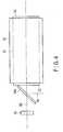
- a second embodiment will now be explained with reference to FIG. 4 .
- the present embodiment is a modification of the first embodiment, the members explained in the first embodiment or members having the same functions as those of the members explained I the first embodiment are denoted with the same reference numerals as much as possible, and a detailed explanation thereof is omitted.
- an optical element assembly 12 includes a rod 22, a mirror 24a, and a light emitting element 26.
- the lens 42 and the light beam intensity adjusting element 44 are omitted herein, but the lens 42 and the light beam intensity adjusting element 44 may be arranged between the light emitting element 26 and the mirror 24a.
- the mirror 24a is disposed on a side of the first end 32 of the rod 22.
- the mirror 24a crosses the central axis C.
- the mirror 24a is disposed in a state of 45° with respect to the first end 32 of the rod 22.
- the mirror 24a reflects light of the first wavelength region and transmits light of the second wavelength region, unlike the mirror 24 explained in the first embodiment.
- the light emitting element 26 emits light of the second wavelength region.
- the light emitting element 26 is disposed in a position, for example, opposed to the first end 32.
- the light emitted from the light emitting element 26 is emitted toward the mirror 24a.
- Disposition of the mirror 24a with respect to the rod 22 can be properly set.
- the mirror 24a is rotated around the central axis C while the mirror 24a maintains the state of 45° with respect to the first end 32, an image of a region of 360° in a direction orthogonal to the central axis C is emitted from the second end 34 through the first end 32 of the rod 22.
- the optical element assembly 12 is capable of transmitting an image of a proper position, as well as an image of a position opposed to the first end 32 of the rod 22, through the rod 22 from the second end of the rod 22 to a position opposed to the second end 34 of the rod 22.
- the optical element assembly 12 includes the transparent rod 22, the mirror 24 or 24a, and the light emitting element 26.
- the rod 22 transmits light of the first wavelength region made incident on the first end 32, emits the light from the second end 34, and absorbs light of the second wavelength region falling out of the first wavelength region.
- the mirror 24 or 24a is disposed on a side of the first end 32 of the rod 22, transmits one of the light of the first wavelength region and the light of the second wavelength region, reflects the other.
- the light of the first wavelength region and the second wavelength region is made incident on the first end 32 of the rod 22.
- the light emitting element 26 emits light of the second wavelength region.
- the light of the second wavelength region is made incident on the first end 32 of the rod 22 through the mirror 24 or 24a.
- the first and the second embodiments provide the optical element assembly 12 capable of adjusting the focal position at higher speed.
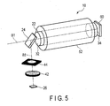
- optical imaging device 10 including the optical element assembly 12 according to the first embodiment and the second embodiment with reference to FIG. 5 .
- the explanation will be made using the optical element assembly 12 explained in the first embodiment, but the optical element assembly 12 explained in the second embodiment may be used.
- the optical imaging device 10 includes the optical element assembly 12 and an image sensor 60.
- the image sensor 60 is disposed on a side of the second end 34 of the rod 22.
- the image sensor 60 is capable of imaging an image transmitted through the mirror 24 and the rod 22 along the central axis C of the rod 22.
- an image formation imaging optical system (optical imaging device 10) is acquired by combining the optical element assembly 12 with the image sensor 60.
- the focus position of a first light beam B1 of the first wavelength region with the rod 22 can be set variable by changing the intensity of a second light beam B2 of the second wavelength region made incident on the first end 32 of the rod 22 from the light emitting element 26, or adjusting the heat radiator 52 to generate temperature distribution.
- the refractive index of the optical element assembly 12 increases by increasing the gradient of the refractive index from the central axis C toward the outside in the radial direction, and the refractive index decreases by decreasing the gradient of the refractive index.
- the example (C) in FIG. 3 enables observation of the subject in the position closer to the first end 32 of the rod 22 than that in the example (B) in FIG. 3 .
- the optical element assembly 12 enables acquisition of an image of a desired distance from the first end 32 of the rod 22, from a position close to the first end 32 of the rod 22 to a distant position (infinity), without mechanically moving the rod 22.
- the optical imaging device 10 according to the present embodiment enables acquisition of an image of a wide focal length, such as close-up photography and distant-view photography, by adjustment at higher speed without mechanical mechanism.
- the following is an explanation of the optical imaging device 10 including the optical element assembly 12 according to the first embodiment with reference to FIG. 6 .
- the present example is a modification of the first example.
- the mirror 24 is disposed in a position opposed to the first end 32 of the rod 22.
- a mirror 62 is disposed on the central axis C of the rod 22. The mirror 24 is positioned between the mirror 62 and the first end 32 of the rod 22.
- the mirror 62 reflects the light of the first wavelength region, and the reflected light is made incident on the first end 32 of the rod 22 through the mirror 24.
- the imaging device 10 is capable of imaging an image of a proper position, as well as an image on the central axis C, with the image sensor 60.
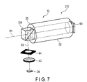
- optical imaging device 10 including the optical element assembly 12 according to the first embodiment and the second embodiment with reference to FIG. 7 .
- the explanation will be made using the optical element assembly 12 explained in the first embodiment, but the optical element assembly 12 explained in the second embodiment may be used.
- a mirror cube 124 is used instead of the mirror 24.
- the mirror cube 124 is a type of the mirror 24.
- the mirror cube 124 can be directly attached to the first end 32 of the rod 22.
- the mirror cube 124 is hard to be affected by air pressure and/or water pressure. For this reason, the mirror cube 24 has higher adaptavility to environments. For this reason, the optical element assembly 12 and the imaging device 10 including the optical element assembly 12 according to the present example can be used even in the water and/or the space.
- the image sensor 60 can also be directly attached to the second end 34 of the rod 22. Accordingly, the optical element assembly 12 according to the present modification enables achievement of an all-solid lens.
- the optical element assembly 12 according to the present example is solid and robust against oscillation.
- optical processing device 210 including the optical element assembly 12 according to the first embodiment and the second embodiment described above with reference to FIG. 8 and FIG. 9 .
- the explanation will be made using the optical element assembly 12 explained in the first embodiment, but the optical element assembly 12 explained in the second embodiment may be used.
- the optical processing device 210 includes the optical element assembly 12 and a laser light source (light emitter of the first wavelength region) 70 to emit the light of the first wavelength region.
- the laser light source 70 emits laser light having proper power density enabling laser processing, as the light of the first wavelength region.
- the laser light source 70 is configured to enter the laser light to the first end 32 of the rod 22 via the mirror 24, and emit the laser light from the second end 34 of the rod 22.
- Proper laser is used as the laser light source 70.
- Examples of the proper laser include UV laser (excimer laser), green laser, CO2 laser, YAG laser, YVO laser, and fiber laser.
- the wavelength region of infrared light is 800 nm to 1000 ⁇ m (1 mm).
- the wavelength region of near-infrared light is 800 nm to 2.5 ⁇ m, as an example.
- the wavelength region of the middle infrared light is 2.5 ⁇ m to 4 ⁇ m, for example.
- the wavelength region of the far infrared light is 4 ⁇ m to 1000 ⁇ m (1 mm), for example.
- the wavelength of the UV laser is, for example, 355 ⁇ m.
- the wavelength of the green laser is, for example, 532 ⁇ m. For this reason, the wavelength regions of the UV laser and the green laser fall out of the wavelength region of the infrared light.
- the wavelength of the CO2 laser is, for example, 10600 ⁇ m.
- the wavelength of the YAG laser and the YVO laser is, for example, 1064 nm.
- the wavelength of the fiber laser is, for example, 1090 ⁇ m. For this reason, the wavelength regions of the CO2 laser, the YAG laser, the YVO laser, and the fiber laser fall within the wavelength region of the infrared light.
- the mirror 24 can be set to transmit the light (laser light) of the first wavelength region and reflect the light of the second wavelength region, even in the same infrared region (wavelength of 800 nm to 1 mm), by a publicly-known manufacturing technique. For this reason, when laser processing is performed using laser light of the wavelength region of the infrared light, such as CO2 laser, YAG laser, YVO laser, and fiber laser, the mirror 24 according to the present example transmits light (laser light) of the first wavelength region and reflects light of the second wavelength region in the infrared region.
- the rod 22 is formed of a material transmitting laser of a proper wavelength region in the infrared region, such as CO2 laser, YAG laser, YVO laser, and fiber laser, without absorbing the laser.
- the second wavelength region is, for example, 850 nm (near infrared region) as described above
- the first wavelength region of the infrared region is, for example, 1064 nm to 10600 nm, and sufficiently longer than the second wavelength region.
- the second wavelength region is preferably a wavelength region falling widely out of the first wavelength region.
- a glass material having absorbency of infrared rays having a wavelength, such as 10600 nm is used as the material of the rod 22.
- a glass material transmitting infrared rays having a wavelength, such as 850 nm is used as the material of the rod 22 according to the present example.
- the material of the rod 22 is selected according to selection of the light beam B2 of the second wavelength region to be absorbed and the light beam B1 of the first wavelength region to be transmitted.
- the focal position of the light of the first wavelength region can be adjusted by adjusting the refractive index on the basis of the temperature distribution extending toward the outside in the radial direction from the central axis C of the rod 22 with the light of the second wavelength region.
- the processing point P (see FIG. 8 ) of laser processing is moved forward and backward along the central axis C by adjusting the refractive index of the rod 22.
- the optical processing device 210 is capable of adjusting the focal position, for example, from a focal position P1 to a focal position P2 serving as a distant focal position, without mechanically moving the lens or the like.
- the optical processing device 210 is capable of adjusting the focal position from the distant focal position P2 to the close focal position P1. This structure enables easy execution of laser processing on, for example, a surface S having projections and depressions.
- the present example enables achievement of the laser processing device (optical processing device) 210 capable of instantly adjusting the position of the processing point.
Landscapes
- Physics & Mathematics (AREA)
- Nonlinear Science (AREA)
- General Physics & Mathematics (AREA)
- Optics & Photonics (AREA)
- Lenses (AREA)
- Lens Barrels (AREA)
- Cameras In General (AREA)
- Blocking Light For Cameras (AREA)
- Cameras Adapted For Combination With Other Photographic Or Optical Apparatuses (AREA)
- Laser Beam Processing (AREA)
- Investigating Or Analysing Materials By Optical Means (AREA)
Abstract
Description
- Embodiments described herein relate generally to an optical element assembly, an optical imaging device, and an optical processing device.
- Focal length is generally adjusted by mechanically changing the position of the lens assembly including a plurality of lenses.
- There are cases where the lens assembly is mechanically moved, such as the case of observing an object moving at high speed. The adjustment speed of the focal length may be delayed, for example, with respect to the moving speed of the object. As described above, in the case of adjusting the focus by mechanically moving the lens assembly, the speed (speediness) of focusing has a limit.
-
-
FIG. 1 is a schematic perspective view illustrating an optical element assembly according to a first embodiment; -
FIG. 2 is a schematic perspective view illustrating a light beam intensity adjusting element inFIG. 1 ; -
FIG. 3 is a schematic diagram illustrating that a focal position of a first light beam is variable when the optical element assembly according to the first embodiment is used; -
FIG. 4 is a schematic perspective view illustrating an optical element assembly according to a second embodiment; -
FIG. 5 is a schematic perspective view illustrating an optical imaging device according to a first example; -
FIG. 6 is a schematic diagram illustrating an optical imaging device according to a second example; -
FIG. 7 is a schematic perspective view illustrating an optical imaging device according to a third example; -
FIG. 8 is a schematic perspective view illustrating an optical processing device according to a fourth example; and -
FIG. 9 is a schematic diagram illustrating that a processing position of a processing surface of a first light beam emitted from a rod of the optical processing device illustrated inFIG. 8 is variable. - The following is an explanation of an
optical element assembly 12 with reference to drawings. The drawings are schematic or conceptual ones. - The problem to be solved by the present embodiment is to provide an optical element assembly, an optical imaging device, and an optical processing device capable of adjusting a focal position at higher speed.
- According to one example, an optical element assembly includes: a transparent rod, a mirror, and a light emitting element. The transparent rod includes a first end and a second end. The transparent rod is configured to transmit light of first wavelength region made incident on the first end and emit the light of the first wavelength region from the second end. The transparent rod is configured to absorb light of a second wavelength region falling out of the first wavelength region. The mirror is disposed on a side of the first end of the rod. The mirror is configured to transmit one of the light of the first wavelength region and the light of the second wavelength region, reflect the other. The light of the first wavelength region and the light of the second wavelength region are made incident on the first end of the rod. The light emitting element is configured to emit light of the second wavelength region. The light of the second wavelength region is made incident on the first end of the rod through the mirror.
- The following is an explanation of the first embodiment with reference to
FIG. 1 to FIG. 3 . - As illustrated in
FIG. 1 , theoptical element assembly 12 according to the present embodiment includes arod 22, amirror 24, and alight emitting element 26. - The
rod 22 is formed of a transparent material and in a columnar shape having afirst end 32 and asecond end 34. The shape of therod 22 is not limited to the columnar shape. Therod 22 is formed symmetrically with respect to the central axis C. Thefirst end 32 and thesecond end 34 are formed as surfaces orthogonal to the central axis C. - The
rod 22 has a diameter of several millimeters to tens of millimeters. Therod 22 has a length of several millimeters to tens of millimeters. The shape and/or the size of therod 22 can be properly set. - The
rod 22 transmits light of first wavelength region and absorbs light of second wavelength region. As a material of therod 22, for example, a glass material having infrared absorbency is used. A proper material is selected as the material of therod 22 depending on the selection of a light beam B1 of the first wavelength region that the user wants to transmit through therod 22, and the selection of a light beam B2 of the second wavelength region that the user wants to absorb with therod 22. - In the present embodiment, the wavelength of the first wavelength region is shorter than the wavelength of the second wavelength region. The first wavelength region is, for example, 550 nm falling within wavelength range (380 nm to 780 nm) of visible light. The second wavelength region is, for example, 850 nm falling within wavelength range (800 nm to 1 mm) of infrared rays. The first wavelength region and the second wavelength region are mere examples, and can be properly set. For this reason, the
rod 22 has infrared absorbency. In some wavelengths to be used, the wavelength of the first wavelength region is longer than the wavelength of the second wavelength region. - Because the
rod 22 is symmetrical with respect to the central axis C, heat is uniformly radiated outward in the radial direction from the central axis C of therod 22. - The
mirror 24 is disposed on a side of thefirst end 32 of therod 22. Themirror 24 crosses the central axis C. Themirror 24 is inclined by, for example, 45° with respect to the central axis C of therod 22. - In the present embodiment, the
mirror 24 transmits first light beam B1 including the first wavelength region, such as visible light, and reflects second light beam B2 including the second wavelength region, such as infrared rays. For example, themirror 24 is a dichroic mirror. Themirror 24 may be a cube-typedichroic mirror 124 illustrated inFIG. 7 . - The
light emitting element 26 is capable of emitting the second light beam B2 of the second wavelength region. Thelight emitting element 26 is capable of switching ON/OFF states. Thelight emitting element 26 emits light in the ON state, and applies the light to themirror 24. - As the
light emitting element 26, for example, a LED or a laser diode (LD) is used. When a laser diode is used as thelight emitting element 26, the light beam thereof approximates to a Gaussian beam. For this reason, when a laser diode is used as thelight emitting element 26, alens 42 and a light beamintensity adjusting element 44 can be omitted. - A
lens 42 is preferably disposed between the infraredlight emitting element 26 and themirror 24. Thelens 42 shapes, for example, the light beam from thelight emitting element 26 into parallel light or the like. - A light beam
intensity adjusting element 44 is preferably disposed between thelens 42 and themirror 24. The light beamintensity adjusting element 44 adjusts the beam profile of the second light beam B2 from thelight emitting element 26. As illustrated inFIG. 2 , the light beamintensity adjusting element 44 provides the transmittance of the second light beam B2 with distribution. The distribution has circular polar coordinates (r, θ) with respect to the X-Y coordinates. The second light beam B2 emitted from thelight emitting element 26 has an axial-symmetrical beam profile directly after passing through the light beamintensity adjusting element 44. - In this state, when the intensity of a cross section of the light beam is I, the beam profile is expressed as follows, as a function of r.

mirror 24 as the second light beam B2, but a beam that is not axial-symmetrical may be made incident on themirror 24. - A
tubular heat radiator 52 is provided around the external circumference of therod 22. Theheat radiator 52 has a cylindrical body. A wall portion of theheat radiator 52 is preferably solid. The whole length of theheat radiator 52 is substantially the same as the whole length of therod 22. Theheat radiator 52 is formed of a material having higher heat conductivity than that of therod 22. Theheat radiator 52 is preferably formed of a metal material with good heat conductivity, such as copper and aluminum alloy. - The
heat radiator 52 is formed of the material with good heat conductivity and in the cylindrical body. In addition, a Peltier element used for various types of cooling devices may be used instead of the cylindrical body. - The following is an explanation of operations of the
optical element assembly 12 according to the present embodiment. - When the
light emitting element 26 emits light, the second light beam B2 emitted from thelight emitting element 26 becomes parallel light through thelens 42. The parallel light passes through the light beamintensity adjusting element 44. The second light beam B2 transmitted through the light beamintensity adjusting element 44 has a beam profile based on Expression (1). An example of the beam profile based on Expression (1) is a Gaussian beam. - The second light beam B2 adjusted to have a beam profile based on Expression (1) is reflected with the
mirror 24. The second light beam B2 adjusted to have a beam profile based on Expression (1) is made incident on thefirst end 32 of therod 22. In this state, themirror 24 is in an adjusted position such that the second light beam B2 adjusted to be axial-symmetrical is made incident on a position in which the central axis of the second light beam B2 agrees with, or substantially agrees with, the central axis C of therod 22. - The
rod 22 absorbs light of the second wavelength region of the second light beam B2 at proper rate, between thefirst end 32 and thesecond end 34. The temperature of therod 22 increases when the second light beam B2 is made incident thereon and therod 22 absorbs the second light beam B2. Therod 22 generates refractive index distribution in accordance with temperature increase. Specifically, the refractive index of therod 22 changes when the second light beam B2 is made incident thereon and therod 22 absorbs the second light beam B2. - In this state, the central axis of the axial-symmetrical second light beam B2 agrees with, or substantially agrees with, the central axis C of the
rod 22. For this reason, the refractive index of therod 22 changes outward in the radial direction from the central axis C. When the temperature increase ΔT in a proper position of therod 22 is sufficiently small, such as ten to twenty, the refractive index distribution of therod 22 linearly changes. The refractive index distribution of therod 22 has a profile similar to Expression (1). When n0 is the refractive index of therod 22 when the temperature distribution between the central axis C and the external circumferential surface of therod 22 is fixed, that is, when therod 22 has no temperature gradient, the change quantity Δn of the refractive index of therod 22 after temperature increase is as follows.
- The
mirror 24 transmits the first light beam B1 from a region opposed to thefirst end 32 of therod 22, and the first light beam B1 is made incident on thefirst end 32 of therod 22. In this operation, the following light beam equation can be used.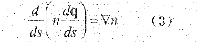
first end 32 of therod 22. - As described above, by making the second light beam B2 of the second wavelength region incident on the
rod 22 and causing temperature change in therod 22, the refractive index of therod 22 can be changed toward the outside in the radial direction with respect to the central axis C of therod 22. For this reason, the first light beam B1 opposed to thefirst end 32 of therod 22, transmitted through themirror 24, and passing between thefirst end 32 and thesecond end 34 of therod 22 is curved (deflected) in accordance with the refractive index. Accordingly, when the second light beam B2 of the second wavelength region is made incident on therod 22 and temperature change is caused in therod 22, therod 22 can be used as a lens. - Part (A) to Part (C) in
FIG. 3 illustrate states in which the refractive index of therod 22 changes without mechanically moving therod 22, themirror 24, thelight emitting element 26, thelens 42, or the light beamintensity adjusting element 44. - Part (A) in
FIG. 3 illustrates a state in which no second light beam B2 is made incident on therod 22 from thelight emitting element 26, and no temperature distribution occurs in therod 22 outward in the radial direction from the central axis C. In this case, therod 22 does not function as a lens, and the first light beam B1 passing through therod 22 is not focused, or focused at infinity. As described above, when the temperature distribution of therod 22 is fixed in the radial direction from the central axis C, the refractive index of therod 22 is fixed. - Part (B) in
FIG. 3 illustrates a state in which the second light beam B2 is made incident on thefirst end 32 of therod 22 from thelight emitting element 26, and temperature distribution is generated in therod 22 outward in the radial direction from the central axis C. For example, by emission of the second light beam B2 from thelight emitting element 26, the refractive index of therod 22 is instantly changed, and the locus of the first light beam B1 is instantly changed. In this case, the temperature is highest at the central axis C of therod 22, and the temperature decreases toward the outside in the radial direction from the central axis C. When the temperature distribution of therod 22 changes, the refractive index of therod 22 changes in accordance with the temperature distribution. In this state, the refractive index in the position along the central axis C is larger than the refractive index in an outside position in the radial direction with respect to the central axis C. Therod 22 in this state becomes equal to, for example, a GRIN lens. Light has a property of being deflected toward a direction with higher refractive index. For this reason, the first light beam B1 from the region opposed to thefirst end 32 of therod 22 is focused, for example, in a position Fb at a proper distance Db from thesecond end 34 of therod 22. - Part (C) in
FIG. 3 illustrates a state in which the second light beam B2 is made incident on thefirst end 32 of therod 22 from thelight emitting element 26, and temperature distribution is generated in therod 22 outward in the radial direction from the central axis C. In this case, the temperature decreases toward the outside in the radial direction from the central axis C of therod 22. In addition, the example illustrated in part (C) inFIG. 3 has a higher temperature gradient toward the outside in the radial direction from the central axis C than that in the example illustrated in part (B) inFIG. 3 . In this state, the first light beam B1 from the region opposed to thefirst end 32 of therod 22 is focused in a position Fc at a proper distance Dc from thesecond end 34 of therod 22. The position Fc is closer to thesecond end 34 of therod 22 than the position illustrated in part (B) ofFIG. 3 is. - As described above, the focal position Fb of the example illustrated in part (B) of
FIG. 3 is longer than the focal position Fc of the example illustrated in part (C) ofFIG. 3 by a length L (= distance Db - distance Dc). In this case, the example illustrated in part (C) inFIG. 3 enables observation of the subject in a position closer to thefirst end 32 of therod 22 than that in the example illustrated in part (B) inFIG. 3 . - In the present embodiment, the
heat radiator 52 is disposed around the external circumference of therod 22. When therod 22 absorbs the second light beam B2, theheat radiator 52 absorbs heat in therod 22, and radiates the heat outward in the radial direction. As the heat radiation quantity with theheat radiator 52 increases, temperature change (temperature gradient) between the central axis C of therod 22 and the external circumferential surface of therod 22 increases by adjustment of the light quantity (light beam intensity) of the second light beam with respect to therod 22. - In the state where the second light beam B2 is made incident on the
first end 32 of therod 22 from thelight emitting element 26, theheat radiator 52 adjusts the temperature gradient ranging from the central axis C of therod 22 toward the outside in the radial direction. With this structure, theheat radiator 52 enables easy control of the refractive index of therod 22 when thesecond light beam 22 is absorbed into therod 22. - The
optical element assembly 12 is capable of changing the focal position F along the central axis C. With this structure, theoptical element assembly 12 according to the present embodiment enables transmission of a signal, for example, to a distant place at high speed. In addition, this structure enables change of the refractive index of therod 22 at high speed without requiring any mechanical element components, such as a galvanometer mirror. Accordingly, this structure enables change of the light beam direction of the first light beam B1 by making the second light beam B2 of the second wavelength region incident on the central axis C of therod 22 from thelight emitting element 26. - With the structure described above, the image formation optical system of the
optical element assembly 12 according to the present embodiment is capable of changing the focus position seamlessly at high speed. Accordingly, the present embodiment provides an optical element assembly capable of adjusting the focal position at higher speed. - The present embodiment illustrates the example of forming the
rod 22 in a circular columnar shape. Therod 22 may be pillars of various shapes, such as an elliptic columnar shape and a rectangular prism shape. In the case of using arod 22 having no circular columnar shape, such as arod 22 of a rectangular prism shape, the temperature distribution around the external circumference of therod 22 may become non-uniform with respect to the central axis C. In this case, the refractive index can be adjusted by adjusting theheat radiator 52 to make the temperature distribution with respect to the central axis C uniform. - A second embodiment will now be explained with reference to
FIG. 4 . The present embodiment is a modification of the first embodiment, the members explained in the first embodiment or members having the same functions as those of the members explained I the first embodiment are denoted with the same reference numerals as much as possible, and a detailed explanation thereof is omitted. - As illustrated in
FIG. 4 , anoptical element assembly 12 according to the present embodiment includes arod 22, amirror 24a, and alight emitting element 26. Thelens 42 and the light beamintensity adjusting element 44 are omitted herein, but thelens 42 and the light beamintensity adjusting element 44 may be arranged between the light emittingelement 26 and themirror 24a. - The
mirror 24a is disposed on a side of thefirst end 32 of therod 22. Themirror 24a crosses the central axis C. Themirror 24a is disposed in a state of 45° with respect to thefirst end 32 of therod 22. Themirror 24a reflects light of the first wavelength region and transmits light of the second wavelength region, unlike themirror 24 explained in the first embodiment. - The
light emitting element 26 emits light of the second wavelength region. Thelight emitting element 26 is disposed in a position, for example, opposed to thefirst end 32. The light emitted from thelight emitting element 26 is emitted toward themirror 24a. - Disposition of the
mirror 24a with respect to therod 22 can be properly set. When themirror 24a is rotated around the central axis C while themirror 24a maintains the state of 45° with respect to thefirst end 32, an image of a region of 360° in a direction orthogonal to the central axis C is emitted from thesecond end 34 through thefirst end 32 of therod 22. - Accordingly, the
optical element assembly 12 according to the present embodiment is capable of transmitting an image of a proper position, as well as an image of a position opposed to thefirst end 32 of therod 22, through therod 22 from the second end of therod 22 to a position opposed to thesecond end 34 of therod 22. - As explained above, the
optical element assembly 12 according to the first and the second embodiment includes thetransparent rod 22, themirror light emitting element 26. Therod 22 transmits light of the first wavelength region made incident on thefirst end 32, emits the light from thesecond end 34, and absorbs light of the second wavelength region falling out of the first wavelength region. Themirror first end 32 of therod 22, transmits one of the light of the first wavelength region and the light of the second wavelength region, reflects the other. The light of the first wavelength region and the second wavelength region is made incident on thefirst end 32 of therod 22. Thelight emitting element 26 emits light of the second wavelength region. The light of the second wavelength region is made incident on thefirst end 32 of therod 22 through themirror - The first and the second embodiments provide the
optical element assembly 12 capable of adjusting the focal position at higher speed. - The following is an explanation of an
optical imaging device 10 including theoptical element assembly 12 according to the first embodiment and the second embodiment with reference toFIG. 5 . The explanation will be made using theoptical element assembly 12 explained in the first embodiment, but theoptical element assembly 12 explained in the second embodiment may be used. - As illustrated in
FIG. 5 , theoptical imaging device 10 according to the present example includes theoptical element assembly 12 and animage sensor 60. - The
image sensor 60 is disposed on a side of thesecond end 34 of therod 22. Theimage sensor 60 is capable of imaging an image transmitted through themirror 24 and therod 22 along the central axis C of therod 22. - In the present example, the change quantity Δn of the refractive index of the rod after temperature increase is set to satisfy, for example,

- According to the present example, an image formation imaging optical system (optical imaging device 10) is acquired by combining the
optical element assembly 12 with theimage sensor 60. - The focus position of a first light beam B1 of the first wavelength region with the
rod 22 can be set variable by changing the intensity of a second light beam B2 of the second wavelength region made incident on thefirst end 32 of therod 22 from thelight emitting element 26, or adjusting theheat radiator 52 to generate temperature distribution. - The refractive index of the
optical element assembly 12 increases by increasing the gradient of the refractive index from the central axis C toward the outside in the radial direction, and the refractive index decreases by decreasing the gradient of the refractive index. - As described above, the example (C) in
FIG. 3 enables observation of the subject in the position closer to thefirst end 32 of therod 22 than that in the example (B) inFIG. 3 . Theoptical element assembly 12 enables acquisition of an image of a desired distance from thefirst end 32 of therod 22, from a position close to thefirst end 32 of therod 22 to a distant position (infinity), without mechanically moving therod 22. Specifically, theoptical imaging device 10 according to the present embodiment enables acquisition of an image of a wide focal length, such as close-up photography and distant-view photography, by adjustment at higher speed without mechanical mechanism. - The following is an explanation of the
optical imaging device 10 including theoptical element assembly 12 according to the first embodiment with reference toFIG. 6 . The present example is a modification of the first example. - As illustrated in
FIG. 6 , themirror 24 is disposed in a position opposed to thefirst end 32 of therod 22. In addition, amirror 62 is disposed on the central axis C of therod 22. Themirror 24 is positioned between themirror 62 and thefirst end 32 of therod 22. - The
mirror 62 reflects the light of the first wavelength region, and the reflected light is made incident on thefirst end 32 of therod 22 through themirror 24. - With this structure, the
imaging device 10 is capable of imaging an image of a proper position, as well as an image on the central axis C, with theimage sensor 60. - The following is an explanation of an
optical imaging device 10 including theoptical element assembly 12 according to the first embodiment and the second embodiment with reference toFIG. 7 . The explanation will be made using theoptical element assembly 12 explained in the first embodiment, but theoptical element assembly 12 explained in the second embodiment may be used. - As illustrated in
FIG. 7 , amirror cube 124 is used instead of themirror 24. Themirror cube 124 is a type of themirror 24. - The
mirror cube 124 can be directly attached to thefirst end 32 of therod 22. Themirror cube 124 is hard to be affected by air pressure and/or water pressure. For this reason, themirror cube 24 has higher adaptavility to environments. For this reason, theoptical element assembly 12 and theimaging device 10 including theoptical element assembly 12 according to the present example can be used even in the water and/or the space. - The
image sensor 60 can also be directly attached to thesecond end 34 of therod 22. Accordingly, theoptical element assembly 12 according to the present modification enables achievement of an all-solid lens. theoptical element assembly 12 according to the present example is solid and robust against oscillation. - The following is an explanation of an
optical processing device 210 including theoptical element assembly 12 according to the first embodiment and the second embodiment described above with reference toFIG. 8 andFIG. 9 . The explanation will be made using theoptical element assembly 12 explained in the first embodiment, but theoptical element assembly 12 explained in the second embodiment may be used. - As illustrated in
FIG. 8 , theoptical processing device 210 according to the present example includes theoptical element assembly 12 and a laser light source (light emitter of the first wavelength region) 70 to emit the light of the first wavelength region. - The
laser light source 70 emits laser light having proper power density enabling laser processing, as the light of the first wavelength region. Thelaser light source 70 is configured to enter the laser light to thefirst end 32 of therod 22 via themirror 24, and emit the laser light from thesecond end 34 of therod 22. - Proper laser is used as the
laser light source 70. Examples of the proper laser include UV laser (excimer laser), green laser, CO2 laser, YAG laser, YVO laser, and fiber laser. - As an example, the wavelength region of infrared light is 800 nm to 1000 µm (1 mm). In the wavelength region, the wavelength region of near-infrared light is 800 nm to 2.5 µm, as an example. The wavelength region of the middle infrared light is 2.5 µm to 4 µm, for example. The wavelength region of the far infrared light is 4 µm to 1000 µm (1 mm), for example.
- The wavelength of the UV laser is, for example, 355 µm. The wavelength of the green laser is, for example, 532 µm. For this reason, the wavelength regions of the UV laser and the green laser fall out of the wavelength region of the infrared light.
- The wavelength of the CO2 laser is, for example, 10600 µm. The wavelength of the YAG laser and the YVO laser is, for example, 1064 nm. The wavelength of the fiber laser is, for example, 1090 µm. For this reason, the wavelength regions of the CO2 laser, the YAG laser, the YVO laser, and the fiber laser fall within the wavelength region of the infrared light.
- The
mirror 24 can be set to transmit the light (laser light) of the first wavelength region and reflect the light of the second wavelength region, even in the same infrared region (wavelength of 800 nm to 1 mm), by a publicly-known manufacturing technique. For this reason, when laser processing is performed using laser light of the wavelength region of the infrared light, such as CO2 laser, YAG laser, YVO laser, and fiber laser, themirror 24 according to the present example transmits light (laser light) of the first wavelength region and reflects light of the second wavelength region in the infrared region. - The
rod 22 is formed of a material transmitting laser of a proper wavelength region in the infrared region, such as CO2 laser, YAG laser, YVO laser, and fiber laser, without absorbing the laser. When the second wavelength region is, for example, 850 nm (near infrared region) as described above, the first wavelength region of the infrared region is, for example, 1064 nm to 10600 nm, and sufficiently longer than the second wavelength region. The second wavelength region is preferably a wavelength region falling widely out of the first wavelength region. For this reason, for example, a glass material having absorbency of infrared rays having a wavelength, such as 10600 nm, is used as the material of therod 22. By contrast, for example, a glass material transmitting infrared rays having a wavelength, such as 850 nm, is used as the material of therod 22 according to the present example. - As described above, the material of the
rod 22 is selected according to selection of the light beam B2 of the second wavelength region to be absorbed and the light beam B1 of the first wavelength region to be transmitted. - As illustrated in
FIG. 9 , the focal position of the light of the first wavelength region can be adjusted by adjusting the refractive index on the basis of the temperature distribution extending toward the outside in the radial direction from the central axis C of therod 22 with the light of the second wavelength region. For this reason, the processing point P (seeFIG. 8 ) of laser processing is moved forward and backward along the central axis C by adjusting the refractive index of therod 22. Accordingly, theoptical processing device 210 is capable of adjusting the focal position, for example, from a focal position P1 to a focal position P2 serving as a distant focal position, without mechanically moving the lens or the like. In addition, theoptical processing device 210 is capable of adjusting the focal position from the distant focal position P2 to the close focal position P1. This structure enables easy execution of laser processing on, for example, a surface S having projections and depressions. - The present example enables achievement of the laser processing device (optical processing device) 210 capable of instantly adjusting the position of the processing point.
- According to the above embodiments, the following clauses can be obtained.
-
Clause 1. An optical element assembly comprising:- a transparent rod including a first end and a second end, the transparent rod being configured to transmit light of first wavelength region made incident on the first end and emit the light of the first wavelength region from the second end, and being configured to absorb light of a second wavelength region falling out of the first wavelength region;
- a mirror disposed on a side of the first end of the rod, being configured to transmit one of the light of the first wavelength region and the light of the second wavelength region, reflect the other, and the light of the first wavelength region and the light of the second wavelength region made incident on the first end of the rod; and
- a light emitting element configured to emit light of the second wavelength region, and the light of the second wavelength region made incident on the first end of the rod through the mirror.
- Clause 2. The optical element assembly according to
clause 1, wherein the rod has a cylindrical shape. - Clause 3. The optical element assembly according to
clause 1 or 2, wherein
the first wavelength region includes a wavelength region of visible light, and
the second wavelength region includes a wavelength region of infrared rays. - Clause 4. The optical element assembly according to any one of
clauses 1 to 3, further comprising:
a tubular heat radiator provided around an external circumference of the rod. - Clause 5. The optical element assembly according to any one of
clauses 1 to 4, wherein the mirror includes a cube-shaped dichroic mirror. - Clause 6. The optical element assembly according to any one of
clauses 1 to 5, comprising:
a lens between the light emitting element and the mirror and configured to shape the light emitted from the light emitting element. - Clause 7. The optical element assembly according to any one of
clauses 1 to 6, comprising:
an adjustment element between the light emitting element and the mirror and configured to adjust intensity of the light made incident on the first end of the rod from the light emitting element through the mirror. - Clause 8. An optical imaging device comprising:
- the optical element assembly according to any one of
clauses 1 to 7; and - an image sensor disposed in a position opposed to the second end of the rod and configured to image the light of the first wavelength region.
- the optical element assembly according to any one of
- Clause 9. The optical imaging device according to clause 8, wherein wavelength of the first wavelength region is shorter than wavelength of the second wavelength region.
-
Clause 10. An optical processing device comprising:- the optical element assembly according to any one of
clauses 1 to 7; and - a light emitter configured to emit the light of the first wavelength region and configured to enter the light to the first end of the rod via the mirror, and emit the light from the second end of the rod.
- the optical element assembly according to any one of
- Clause 11. The optical processing device according to
clause 10, wherein
the second wavelength region includes a wavelength region of infrared rays, and
the light of the first wavelength region includes laser light of wavelength region different from the infrared rays. -
Clause 12. The optical processing device according toclause 10, wherein
the second wavelength region includes wavelength region of infrared rays, and
the light of the first wavelength region includes infrared rays of wavelength region different from the infrared rays of the second wavelength region.
While certain arrangements have been described, these arrangements have been presented by way of example only, and are not intended to limit the scope of the inventions. Indeed, the apparatuses described herein may be embodied in a variety of other forms; furthermore, various omissions, substitutions and changes in the form of the apparatuses described herein may be made.
Claims (12)
- An optical element assembly comprising:a transparent rod including a first end and a second end, the transparent rod being configured to transmit light of first wavelength region made incident on the first end and emit the light of the first wavelength region from the second end, and being configured to absorb light of a second wavelength region falling out of the first wavelength region;a mirror disposed on a side of the first end of the rod, being configured to transmit one of the light of the first wavelength region and the light of the second wavelength region, reflect the other, and the light of the first wavelength region and the light of the second wavelength region made incident on the first end of the rod; anda light emitting element configured to emit light of the second wavelength region, and the light of the second wavelength region made incident on the first end of the rod through the mirror.
- The optical element assembly according to claim 1, wherein the rod has a cylindrical shape.
- The optical element assembly according to claim 1 or 2, wherein
the first wavelength region includes a wavelength region of visible light, and
the second wavelength region includes a wavelength region of infrared rays. - The optical element assembly according to any one of claims 1 to 3, further comprising:
a tubular heat radiator provided around an external circumference of the rod. - The optical element assembly according to any one of claims 1 to 4, wherein the mirror includes a cube-shaped dichroic mirror.
- The optical element assembly according to any one of claims 1 to 5, comprising:
a lens between the light emitting element and the mirror and configured to shape the light emitted from the light emitting element. - The optical element assembly according to any one of claims 1 to 6, comprising:
an adjustment element between the light emitting element and the mirror and configured to adjust intensity of the light made incident on the first end of the rod from the light emitting element through the mirror. - An optical imaging device comprising:the optical element assembly according to any one of claims 1 to 7; andan image sensor disposed in a position opposed to the second end of the rod and configured to image the light of the first wavelength region.
- The optical imaging device according to claim 8, wherein wavelength of the first wavelength region is shorter than wavelength of the second wavelength region.
- An optical processing device comprising:the optical element assembly according to any one of claims 1 to 7; anda light emitter configured to emit the light of the first wavelength region and configured to enter the light to the first end of the rod via the mirror, and emit the light from the second end of the rod.
- The optical processing device according to claim 10, wherein
the second wavelength region includes a wavelength region of infrared rays, and
the light of the first wavelength region includes laser light of wavelength region different from the infrared rays. - The optical processing device according to claim 10, wherein
the second wavelength region includes wavelength region of infrared rays, and
the light of the first wavelength region includes infrared rays of wavelength region different from the infrared rays of the second wavelength region.
Applications Claiming Priority (1)
| Application Number | Priority Date | Filing Date | Title |
|---|---|---|---|
| JP2019168955A JP7214600B2 (en) | 2019-09-18 | 2019-09-18 | Optical element assembly, optical imaging device, and optical processing device |
Publications (2)
| Publication Number | Publication Date |
|---|---|
| EP3796054A1 true EP3796054A1 (en) | 2021-03-24 |
| EP3796054B1 EP3796054B1 (en) | 2025-08-27 |
Family
ID=69742929
Family Applications (1)
| Application Number | Title | Priority Date | Filing Date |
|---|---|---|---|
| EP20160059.0A Active EP3796054B1 (en) | 2019-09-18 | 2020-02-28 | Optical element assembly, optical imaging device, and optical processing device |
Country Status (3)
| Country | Link |
|---|---|
| US (1) | US11803094B2 (en) |
| EP (1) | EP3796054B1 (en) |
| JP (1) | JP7214600B2 (en) |
Citations (1)
| Publication number | Priority date | Publication date | Assignee | Title |
|---|---|---|---|---|
| JP5261646B2 (en) * | 2009-07-08 | 2013-08-14 | 独立行政法人産業技術総合研究所 | Thermal lens forming element |
Family Cites Families (12)
| Publication number | Priority date | Publication date | Assignee | Title |
|---|---|---|---|---|
| JP3869922B2 (en) * | 1997-12-26 | 2007-01-17 | 日本ビクター株式会社 | Optical element, deflection element using optical element, light control method, and light control apparatus |
| US6827450B1 (en) * | 2001-10-05 | 2004-12-07 | Jds Uniphase Corporation | Scrolling color projection system |
| WO2004053531A2 (en) * | 2002-12-09 | 2004-06-24 | Oree, Advanced Illumination Solutions Inc. | Flexible optical device |
| JP2006047484A (en) * | 2004-08-02 | 2006-02-16 | Ricoh Co Ltd | Optical element and optical device |
| JP4822113B2 (en) * | 2006-02-22 | 2011-11-24 | 独立行政法人産業技術総合研究所 | Optical deflection method and optical deflection apparatus |
| JP5370711B2 (en) * | 2007-12-25 | 2013-12-18 | 独立行政法人産業技術総合研究所 | Thermal lens forming element |
| JP5305128B2 (en) * | 2008-05-14 | 2013-10-02 | 株式会社リコー | Droplet optical device |
| CN101349853A (en) * | 2008-08-28 | 2009-01-21 | 福州高意通讯有限公司 | Non-moving type adjustable focal length lens and light beam scanning structure |
| CN105305207A (en) | 2014-11-25 | 2016-02-03 | 北京国科世纪激光技术有限公司 | End-pumped single-pass traveling wave laser amplifier |
| WO2017005604A1 (en) * | 2015-07-07 | 2017-01-12 | Koninklijke Philips N.V. | Light emitting apparatus |
| PL240676B1 (en) * | 2017-09-13 | 2022-05-16 | Univ Im Adama Mickiewicza W Poznaniu | Method for creation of multi-planar image using the varifocal lens and the device for the execution of this method |
| CN111095351B (en) | 2017-09-14 | 2023-06-20 | 株式会社日立高新技术 | Charged particle microscope device and wide-angle image generation method |
-
2019
- 2019-09-18 JP JP2019168955A patent/JP7214600B2/en active Active
-
2020
- 2020-02-27 US US16/802,828 patent/US11803094B2/en active Active
- 2020-02-28 EP EP20160059.0A patent/EP3796054B1/en active Active
Patent Citations (1)
| Publication number | Priority date | Publication date | Assignee | Title |
|---|---|---|---|---|
| JP5261646B2 (en) * | 2009-07-08 | 2013-08-14 | 独立行政法人産業技術総合研究所 | Thermal lens forming element |
Non-Patent Citations (1)
| Title |
|---|
| TAWY GORONWY ET AL: "Population Lensing in Alexandrite Lasers", 2019 CONFERENCE ON LASERS AND ELECTRO-OPTICS EUROPE & EUROPEAN QUANTUM ELECTRONICS CONFERENCE (CLEO/EUROPE-EQEC), IEEE, 23 June 2019 (2019-06-23), pages 1, XP033631167, DOI: 10.1109/CLEOE-EQEC.2019.8872475 * |
Also Published As
| Publication number | Publication date |
|---|---|
| US20210080801A1 (en) | 2021-03-18 |
| EP3796054B1 (en) | 2025-08-27 |
| JP2021047268A (en) | 2021-03-25 |
| US11803094B2 (en) | 2023-10-31 |
| JP7214600B2 (en) | 2023-01-30 |
Similar Documents
| Publication | Publication Date | Title |
|---|---|---|
| EP1258743B1 (en) | Imaging optical instrument | |
| JP2016524723A (en) | Method for forming a TIR optical fiber lens | |
| US20140161391A1 (en) | Optical module and optical transmission method | |
| JP2016109517A (en) | Laser radar device | |
| KR102438578B1 (en) | Heatless laser optics made of plastic | |
| US11520173B2 (en) | Transmission type adaptive optical system | |
| EP0978748B1 (en) | Multiple light source unit and optical system using the same | |
| JP6442432B2 (en) | Optical device manufacturing method, laser device manufacturing method, and laser device beam quality adjustment method | |
| CN110004496A (en) | A ring laser heating system | |
| EP3796054B1 (en) | Optical element assembly, optical imaging device, and optical processing device | |
| US10240974B2 (en) | Infrared projector and infrared observation system | |
| JP2005157358A (en) | Refractivity/diffractive hybrid type lens for beam shaping specially for high output diode laser | |
| EP3682284B1 (en) | Method of creating a multi-planar image by using varifocal lenses and a device to realize this method | |
| CN221019128U (en) | Optical module and double-facula laser system | |
| JP2017223780A (en) | Optical device and laser apparatus | |
| CN109494551B (en) | Disc laser | |
| CN112736632A (en) | Structured light laser with built-in diffraction lens | |
| JP2020060725A (en) | Laser oscillator and laser processing equipment using the same | |
| JP2019203867A (en) | Confocal displacement meter | |
| JP6420550B2 (en) | Laser cutting device | |
| WO2023054466A1 (en) | Optical connector | |
| JP2012141515A (en) | Fluid optical element, laser light source device and laser processing device | |
| JP5667344B2 (en) | Laser emission unit | |
| JP2005014018A (en) | Laser processing equipment | |
| CN114002702B (en) | F-P cavity-based laser and associated radiation transmission three-dimensional imaging device and method thereof |
Legal Events
| Date | Code | Title | Description |
|---|---|---|---|
| PUAI | Public reference made under article 153(3) epc to a published international application that has entered the european phase |
Free format text: ORIGINAL CODE: 0009012 |
|
| STAA | Information on the status of an ep patent application or granted ep patent |
Free format text: STATUS: REQUEST FOR EXAMINATION WAS MADE |
|
| 17P | Request for examination filed |
Effective date: 20200228 |
|
| AK | Designated contracting states |
Kind code of ref document: A1 Designated state(s): AL AT BE BG CH CY CZ DE DK EE ES FI FR GB GR HR HU IE IS IT LI LT LU LV MC MK MT NL NO PL PT RO RS SE SI SK SM TR |
|
| AX | Request for extension of the european patent |
Extension state: BA ME |
|
| STAA | Information on the status of an ep patent application or granted ep patent |
Free format text: STATUS: EXAMINATION IS IN PROGRESS |
|
| 17Q | First examination report despatched |
Effective date: 20230405 |
|
| GRAP | Despatch of communication of intention to grant a patent |
Free format text: ORIGINAL CODE: EPIDOSNIGR1 |
|
| STAA | Information on the status of an ep patent application or granted ep patent |
Free format text: STATUS: GRANT OF PATENT IS INTENDED |
|
| GRAJ | Information related to disapproval of communication of intention to grant by the applicant or resumption of examination proceedings by the epo deleted |
Free format text: ORIGINAL CODE: EPIDOSDIGR1 |
|
| STAA | Information on the status of an ep patent application or granted ep patent |
Free format text: STATUS: EXAMINATION IS IN PROGRESS |
|
| GRAP | Despatch of communication of intention to grant a patent |
Free format text: ORIGINAL CODE: EPIDOSNIGR1 |
|
| STAA | Information on the status of an ep patent application or granted ep patent |
Free format text: STATUS: GRANT OF PATENT IS INTENDED |
|
| INTG | Intention to grant announced |
Effective date: 20250310 |
|
| RAP3 | Party data changed (applicant data changed or rights of an application transferred) |
Owner name: KABUSHIKI KAISHA TOSHIBA |
|
| INTC | Intention to grant announced (deleted) | ||
| INTG | Intention to grant announced |
Effective date: 20250403 |
|
| GRAS | Grant fee paid |
Free format text: ORIGINAL CODE: EPIDOSNIGR3 |
|
| GRAA | (expected) grant |
Free format text: ORIGINAL CODE: 0009210 |
|
| STAA | Information on the status of an ep patent application or granted ep patent |
Free format text: STATUS: THE PATENT HAS BEEN GRANTED |
|
| AK | Designated contracting states |
Kind code of ref document: B1 Designated state(s): AL AT BE BG CH CY CZ DE DK EE ES FI FR GB GR HR HU IE IS IT LI LT LU LV MC MK MT NL NO PL PT RO RS SE SI SK SM TR |
|
| REG | Reference to a national code |
Ref country code: GB Ref legal event code: FG4D |
|
| REG | Reference to a national code |
Ref country code: CH Ref legal event code: EP |
|
| REG | Reference to a national code |
Ref country code: DE Ref legal event code: R096 Ref document number: 602020057265 Country of ref document: DE |
|
| REG | Reference to a national code |
Ref country code: IE Ref legal event code: FG4D |
|
| REG | Reference to a national code |
Ref country code: NL Ref legal event code: MP Effective date: 20250827 |
|
| PG25 | Lapsed in a contracting state [announced via postgrant information from national office to epo] |
Ref country code: IS Free format text: LAPSE BECAUSE OF FAILURE TO SUBMIT A TRANSLATION OF THE DESCRIPTION OR TO PAY THE FEE WITHIN THE PRESCRIBED TIME-LIMIT Effective date: 20251227 |
|
| PG25 | Lapsed in a contracting state [announced via postgrant information from national office to epo] |
Ref country code: NO Free format text: LAPSE BECAUSE OF FAILURE TO SUBMIT A TRANSLATION OF THE DESCRIPTION OR TO PAY THE FEE WITHIN THE PRESCRIBED TIME-LIMIT Effective date: 20251127 |
|
| REG | Reference to a national code |
Ref country code: LT Ref legal event code: MG9D |
|
| PG25 | Lapsed in a contracting state [announced via postgrant information from national office to epo] |
Ref country code: PT Free format text: LAPSE BECAUSE OF FAILURE TO SUBMIT A TRANSLATION OF THE DESCRIPTION OR TO PAY THE FEE WITHIN THE PRESCRIBED TIME-LIMIT Effective date: 20251229 |
|
| PG25 | Lapsed in a contracting state [announced via postgrant information from national office to epo] |
Ref country code: FI Free format text: LAPSE BECAUSE OF FAILURE TO SUBMIT A TRANSLATION OF THE DESCRIPTION OR TO PAY THE FEE WITHIN THE PRESCRIBED TIME-LIMIT Effective date: 20250827 |
|
| PG25 | Lapsed in a contracting state [announced via postgrant information from national office to epo] |
Ref country code: HR Free format text: LAPSE BECAUSE OF FAILURE TO SUBMIT A TRANSLATION OF THE DESCRIPTION OR TO PAY THE FEE WITHIN THE PRESCRIBED TIME-LIMIT Effective date: 20250827 Ref country code: NL Free format text: LAPSE BECAUSE OF FAILURE TO SUBMIT A TRANSLATION OF THE DESCRIPTION OR TO PAY THE FEE WITHIN THE PRESCRIBED TIME-LIMIT Effective date: 20250827 |
|
| PG25 | Lapsed in a contracting state [announced via postgrant information from national office to epo] |
Ref country code: GR Free format text: LAPSE BECAUSE OF FAILURE TO SUBMIT A TRANSLATION OF THE DESCRIPTION OR TO PAY THE FEE WITHIN THE PRESCRIBED TIME-LIMIT Effective date: 20251128 |
|
| PG25 | Lapsed in a contracting state [announced via postgrant information from national office to epo] |
Ref country code: SE Free format text: LAPSE BECAUSE OF FAILURE TO SUBMIT A TRANSLATION OF THE DESCRIPTION OR TO PAY THE FEE WITHIN THE PRESCRIBED TIME-LIMIT Effective date: 20250827 |
|
| PG25 | Lapsed in a contracting state [announced via postgrant information from national office to epo] |
Ref country code: LV Free format text: LAPSE BECAUSE OF FAILURE TO SUBMIT A TRANSLATION OF THE DESCRIPTION OR TO PAY THE FEE WITHIN THE PRESCRIBED TIME-LIMIT Effective date: 20250827 |
|
| PG25 | Lapsed in a contracting state [announced via postgrant information from national office to epo] |
Ref country code: BG Free format text: LAPSE BECAUSE OF FAILURE TO SUBMIT A TRANSLATION OF THE DESCRIPTION OR TO PAY THE FEE WITHIN THE PRESCRIBED TIME-LIMIT Effective date: 20250827 Ref country code: PL Free format text: LAPSE BECAUSE OF FAILURE TO SUBMIT A TRANSLATION OF THE DESCRIPTION OR TO PAY THE FEE WITHIN THE PRESCRIBED TIME-LIMIT Effective date: 20250827 |
|
| PG25 | Lapsed in a contracting state [announced via postgrant information from national office to epo] |
Ref country code: RS Free format text: LAPSE BECAUSE OF FAILURE TO SUBMIT A TRANSLATION OF THE DESCRIPTION OR TO PAY THE FEE WITHIN THE PRESCRIBED TIME-LIMIT Effective date: 20251127 |
|
| PG25 | Lapsed in a contracting state [announced via postgrant information from national office to epo] |
Ref country code: ES Free format text: LAPSE BECAUSE OF FAILURE TO SUBMIT A TRANSLATION OF THE DESCRIPTION OR TO PAY THE FEE WITHIN THE PRESCRIBED TIME-LIMIT Effective date: 20250827 |
|
| REG | Reference to a national code |
Ref country code: AT Ref legal event code: MK05 Ref document number: 1830551 Country of ref document: AT Kind code of ref document: T Effective date: 20250827 |
|
| PG25 | Lapsed in a contracting state [announced via postgrant information from national office to epo] |
Ref country code: SM Free format text: LAPSE BECAUSE OF FAILURE TO SUBMIT A TRANSLATION OF THE DESCRIPTION OR TO PAY THE FEE WITHIN THE PRESCRIBED TIME-LIMIT Effective date: 20250827 |
|
| PG25 | Lapsed in a contracting state [announced via postgrant information from national office to epo] |
Ref country code: DK Free format text: LAPSE BECAUSE OF FAILURE TO SUBMIT A TRANSLATION OF THE DESCRIPTION OR TO PAY THE FEE WITHIN THE PRESCRIBED TIME-LIMIT Effective date: 20250827 |
|
| PGFP | Annual fee paid to national office [announced via postgrant information from national office to epo] |
Ref country code: DE Payment date: 20260102 Year of fee payment: 7 |
|
| PG25 | Lapsed in a contracting state [announced via postgrant information from national office to epo] |
Ref country code: AT Free format text: LAPSE BECAUSE OF FAILURE TO SUBMIT A TRANSLATION OF THE DESCRIPTION OR TO PAY THE FEE WITHIN THE PRESCRIBED TIME-LIMIT Effective date: 20250827 |
|
| PG25 | Lapsed in a contracting state [announced via postgrant information from national office to epo] |
Ref country code: IT Free format text: LAPSE BECAUSE OF FAILURE TO SUBMIT A TRANSLATION OF THE DESCRIPTION OR TO PAY THE FEE WITHIN THE PRESCRIBED TIME-LIMIT Effective date: 20250827 |
|
| PG25 | Lapsed in a contracting state [announced via postgrant information from national office to epo] |
Ref country code: CZ Free format text: LAPSE BECAUSE OF FAILURE TO SUBMIT A TRANSLATION OF THE DESCRIPTION OR TO PAY THE FEE WITHIN THE PRESCRIBED TIME-LIMIT Effective date: 20250827 |
|
| PG25 | Lapsed in a contracting state [announced via postgrant information from national office to epo] |
Ref country code: EE Free format text: LAPSE BECAUSE OF FAILURE TO SUBMIT A TRANSLATION OF THE DESCRIPTION OR TO PAY THE FEE WITHIN THE PRESCRIBED TIME-LIMIT Effective date: 20250827 Ref country code: SK Free format text: LAPSE BECAUSE OF FAILURE TO SUBMIT A TRANSLATION OF THE DESCRIPTION OR TO PAY THE FEE WITHIN THE PRESCRIBED TIME-LIMIT Effective date: 20250827 |