EP3796053A1 - Ophthalmische linse, herstellungsverfahren dafür und brille mit der ophthalmischen linse - Google Patents
Ophthalmische linse, herstellungsverfahren dafür und brille mit der ophthalmischen linse Download PDFInfo
- Publication number
- EP3796053A1 EP3796053A1 EP19306140.5A EP19306140A EP3796053A1 EP 3796053 A1 EP3796053 A1 EP 3796053A1 EP 19306140 A EP19306140 A EP 19306140A EP 3796053 A1 EP3796053 A1 EP 3796053A1
- Authority
- EP
- European Patent Office
- Prior art keywords
- ophthalmic lens
- layer
- edge surface
- structural element
- preshaped
- Prior art date
- Legal status (The legal status is an assumption and is not a legal conclusion. Google has not performed a legal analysis and makes no representation as to the accuracy of the status listed.)
- Pending
Links
Images


Classifications
-
- G—PHYSICS
- G02—OPTICS
- G02C—SPECTACLES; SUNGLASSES OR GOGGLES INSOFAR AS THEY HAVE THE SAME FEATURES AS SPECTACLES; CONTACT LENSES
- G02C7/00—Optical parts
-
- G—PHYSICS
- G02—OPTICS
- G02C—SPECTACLES; SUNGLASSES OR GOGGLES INSOFAR AS THEY HAVE THE SAME FEATURES AS SPECTACLES; CONTACT LENSES
- G02C1/00—Assemblies of lenses with bridges or browbars
- G02C1/10—Special mounting grooves in the rim or on the lens
-
- B—PERFORMING OPERATIONS; TRANSPORTING
- B29—WORKING OF PLASTICS; WORKING OF SUBSTANCES IN A PLASTIC STATE IN GENERAL
- B29D—PRODUCING PARTICULAR ARTICLES FROM PLASTICS OR FROM SUBSTANCES IN A PLASTIC STATE
- B29D11/00—Producing optical elements, e.g. lenses or prisms
- B29D11/00865—Applying coatings; tinting; colouring
- B29D11/00923—Applying coatings; tinting; colouring on lens surfaces for colouring or tinting
-
- C—CHEMISTRY; METALLURGY
- C09—DYES; PAINTS; POLISHES; NATURAL RESINS; ADHESIVES; COMPOSITIONS NOT OTHERWISE PROVIDED FOR; APPLICATIONS OF MATERIALS NOT OTHERWISE PROVIDED FOR
- C09D—COATING COMPOSITIONS, e.g. PAINTS, VARNISHES OR LACQUERS; FILLING PASTES; CHEMICAL PAINT OR INK REMOVERS; INKS; CORRECTING FLUIDS; WOODSTAINS; PASTES OR SOLIDS FOR COLOURING OR PRINTING; USE OF MATERIALS THEREFOR
- C09D101/00—Coating compositions based on cellulose, modified cellulose, or cellulose derivatives
- C09D101/08—Cellulose derivatives
- C09D101/10—Esters of organic acids
- C09D101/14—Mixed esters, e.g. cellulose acetate-butyrate
-
- C—CHEMISTRY; METALLURGY
- C09—DYES; PAINTS; POLISHES; NATURAL RESINS; ADHESIVES; COMPOSITIONS NOT OTHERWISE PROVIDED FOR; APPLICATIONS OF MATERIALS NOT OTHERWISE PROVIDED FOR
- C09D—COATING COMPOSITIONS, e.g. PAINTS, VARNISHES OR LACQUERS; FILLING PASTES; CHEMICAL PAINT OR INK REMOVERS; INKS; CORRECTING FLUIDS; WOODSTAINS; PASTES OR SOLIDS FOR COLOURING OR PRINTING; USE OF MATERIALS THEREFOR
- C09D163/00—Coating compositions based on epoxy resins; Coating compositions based on derivatives of epoxy resins
-
- C—CHEMISTRY; METALLURGY
- C09—DYES; PAINTS; POLISHES; NATURAL RESINS; ADHESIVES; COMPOSITIONS NOT OTHERWISE PROVIDED FOR; APPLICATIONS OF MATERIALS NOT OTHERWISE PROVIDED FOR
- C09D—COATING COMPOSITIONS, e.g. PAINTS, VARNISHES OR LACQUERS; FILLING PASTES; CHEMICAL PAINT OR INK REMOVERS; INKS; CORRECTING FLUIDS; WOODSTAINS; PASTES OR SOLIDS FOR COLOURING OR PRINTING; USE OF MATERIALS THEREFOR
- C09D167/00—Coating compositions based on polyesters obtained by reactions forming a carboxylic ester link in the main chain; Coating compositions based on derivatives of such polymers
-
- C—CHEMISTRY; METALLURGY
- C09—DYES; PAINTS; POLISHES; NATURAL RESINS; ADHESIVES; COMPOSITIONS NOT OTHERWISE PROVIDED FOR; APPLICATIONS OF MATERIALS NOT OTHERWISE PROVIDED FOR
- C09D—COATING COMPOSITIONS, e.g. PAINTS, VARNISHES OR LACQUERS; FILLING PASTES; CHEMICAL PAINT OR INK REMOVERS; INKS; CORRECTING FLUIDS; WOODSTAINS; PASTES OR SOLIDS FOR COLOURING OR PRINTING; USE OF MATERIALS THEREFOR
- C09D175/00—Coating compositions based on polyureas or polyurethanes; Coating compositions based on derivatives of such polymers
- C09D175/04—Polyurethanes
-
- C—CHEMISTRY; METALLURGY
- C09—DYES; PAINTS; POLISHES; NATURAL RESINS; ADHESIVES; COMPOSITIONS NOT OTHERWISE PROVIDED FOR; APPLICATIONS OF MATERIALS NOT OTHERWISE PROVIDED FOR
- C09D—COATING COMPOSITIONS, e.g. PAINTS, VARNISHES OR LACQUERS; FILLING PASTES; CHEMICAL PAINT OR INK REMOVERS; INKS; CORRECTING FLUIDS; WOODSTAINS; PASTES OR SOLIDS FOR COLOURING OR PRINTING; USE OF MATERIALS THEREFOR
- C09D7/00—Features of coating compositions, not provided for in group C09D5/00; Processes for incorporating ingredients in coating compositions
- C09D7/40—Additives
- C09D7/60—Additives non-macromolecular
- C09D7/61—Additives non-macromolecular inorganic
-
- G—PHYSICS
- G02—OPTICS
- G02B—OPTICAL ELEMENTS, SYSTEMS OR APPARATUS
- G02B1/00—Optical elements characterised by the material of which they are made; Optical coatings for optical elements
- G02B1/10—Optical coatings produced by application to, or surface treatment of, optical elements
-
- G—PHYSICS
- G02—OPTICS
- G02B—OPTICAL ELEMENTS, SYSTEMS OR APPARATUS
- G02B27/00—Optical systems or apparatus not provided for by any of the groups G02B1/00 - G02B26/00, G02B30/00
- G02B27/0018—Optical systems or apparatus not provided for by any of the groups G02B1/00 - G02B26/00, G02B30/00 with means for preventing ghost images
-
- B—PERFORMING OPERATIONS; TRANSPORTING
- B29—WORKING OF PLASTICS; WORKING OF SUBSTANCES IN A PLASTIC STATE IN GENERAL
- B29D—PRODUCING PARTICULAR ARTICLES FROM PLASTICS OR FROM SUBSTANCES IN A PLASTIC STATE
- B29D11/00—Producing optical elements, e.g. lenses or prisms
- B29D11/00009—Production of simple or compound lenses
- B29D11/00432—Auxiliary operations, e.g. machines for filling the moulds
Definitions
- This disclosure relates generally to an ophthalmic lens, a method of manufacturing the ophthalmic lens, and an eyewear comprising the ophthalmic lens.
- a coating material may be introduced on the edge of an ophthalmic lens as an edge coating for various reasons.
- an opaque coating may be deposited on the edge of an ophthalmic lens to reduce visibility of myopia rings and white rings for aesthetic purposes. Examples of a white ring and a myopia ring are shown in FIG. 1A and FIG. 1B as 112 and 114, respectively.
- the myopia rings and white rings may result due to internal reflection of light through the ophthalmic lens.
- the edge coating should have good opacity, finishing, mechanical, and adhesion properties to allow masking of the myopia rings and white rings.
- an operator may apply the coating material on the edge of an ophthalmic lens using a marker pen or a brush, or by spray coating.
- the coating material is applied onto the edge surface of the ophthalmic lens only, without any of the coating material being coated on the optical surfaces of the ophthalmic lens.
- the white ring and the myopia ring may be masked so that they are less noticeable than before.
- Example of an edge surface of the ophthalmic lens having a coating material disposed thereon so as to mask the white ring and the myopia ring are shown in FIG. 1A and FIG. 1B as 122 and 124, respectively.
- FIG. 2A is a schematic diagram showing an edge coating 202 disposed on an edge surface and on a safety bevel 224 present between the edge surface and the first optical surface 220 of an ophthalmic lens 230 according to an embodiment.
- the edge surface of the ophthalmic lens 230 is defined by a surface connecting the first optical surface 220 and the second optical surface 222.
- the edge surface of the ophthalmic lens 230 comprises a lens bevel 226. As depicted in the figure, there is no overflow on the first optical surface 220 and the second optical surface 222 of the ophthalmic lens 230.
- FIG. 2B is a schematic diagram showing an edge coating 202 disposed on an edge surface and on a safety bevel 224 present between the edge surface and the first optical surface 220 of an ophthalmic lens 230.
- edge coating 202 may accidentally be removed.
- an optical lens edge comprises multiple facets, for example, it is very difficult to ensure complete coating coverage on each and every facet, while not introducing overflows on the optical surfaces.
- an ophthalmic lens comprising a first optical surface, an opposing second optical surface and an edge surface connecting the first optical surface and the second optical surface, wherein the edge surface is planar.
- the ophthalmic lens further comprises a first layer disposed on the edge surface, wherein the first layer comprises a coating material effective to reduce a reflection caused by a profile of the edge surface, and wherein (a) the first layer defines a structural element for fastening the ophthalmic lens to an eyewear frame, or (b) the ophthalmic lens further comprises a second layer disposed on the first layer, wherein the second layer defines a structural element for fastening the ophthalmic lens to an eyewear frame.
- the ophthalmic lens is as described in the claims.
- a method of manufacturing an ophthalmic lens comprising providing an ophthalmic lens comprising a first optical surface, an opposing second optical surface and an edge surface connecting the first optical surface and the second optical surface, wherein the edge surface is planar; forming a first layer comprising a coating material effective to reduce a reflection caused by a profile of the edge surface, on the edge surface of the ophthalmic lens; and (a) wherein the first layer defines a structural element for fastening the ophthalmic lens to an eyewear frame, or (b) forming a second layer on the first layer, wherein the second layer defines a structural element for fastening the ophthalmic lens to an eyewear frame.
- the method of manufacturing an ophthalmic lens is as described in the claims.
- an eyewear comprising an eyewear frame and an ophthalmic lens according to the first aspect.
- the eyewear is as described in the claims.
- Embodiments discussed herein are merely representative and do not limit the scope of the invention. It will also be obvious to one skilled in the art that all the technical features that are defined relative to a process can be transposed, individually or in combination, to a device and conversely, all the technical features relative to a device can be transposed, individually or in combination, to a process.
- an ophthalmic lens in which the edge surface connecting the first optical surface and the second optical surface is planar.
- the planar edge surface helps to reduce or prevent myopia rings, which may be caused by total internal reflection when light travels from the lens edge to the air gap between the lens and the frame, and may be generated due to reflection of light from one or both of the optical surfaces and/or the edge surface. This is particularly true at the lens edges, which, oftentimes, have been shaped in order to be fitted into the frame.
- the edge surface of a lens comprises a lens bevel structure and/or other possible geometries, they introduce various surfaces onto the edge surface, all of which constitute a profile of the edge surface. Areas of light reflections at various angles and directions are introduced, which further contribute to appearance of myopia rings.
- a coating material effective to reduce a reflection on the planar edge surface of an ophthalmic lens disclosed herein allows formation of a coating layer comprising the material with improved uniformity in terms of thickness and/or surface coverage, thereby reducing or eliminating defects.
- the edge surface is planar, it is at least substantially free or free from reflections from angular edges of a lens bevel otherwise present in state of the art ophthalmic lenses, thereby effectively reducing multiplied reflection from the first optical surface and the second optical surface of the ophthalmic lenses. In so doing, visibility of the myopia rings otherwise appearing along the perimeter of the ophthalmic lens face may be reduced or eliminated more effectively.
- the coating material effective to reduce a reflection caused by a profile of the edge surface is disposed on a planar surface, this provides ease in coating of the material to suppress myopia rings efficiently.
- ophthalmic lens refers to any type of lens intended to be supported by a wearer's face in the form of an eyewear, whereby the term “eyewear” refers generally to items and accessories worn on or over the eyes, which may be for purposes of improving or enhancing visual acuity, for protecting against the environment, for fashion, or for adornment.
- eyewear may include eyeglasses, goggles, or other objects on or worn over the eyes, or head-mounted devices.
- Eyeglasses also termed herein as glasses or spectacles, may include sunglasses, prescription glasses, prescription sunglasses, transitional glasses, reading glasses, safety glasses, novelty glasses, costume glasses, 3D glasses, fashion glasses, and the like.
- ophthalmic lens examples include non-corrective lenses, semi-finished lens blanks, and corrective lenses, such as progressive addition lenses, unifocal or multifocal lenses.
- the term may also include one or more of prescription, non-prescription, reflective, anti-reflective, magnifying, polarizing, filtering, anti-scratch, colored, tinted, clear, anti-fogging, ultraviolet (UV) light protected, or other lenses.
- Further examples of ophthalmic lens include active lens such as photochromic lens, electrochromic lens, fluidic lens, or liquid crystal lens; electronic lens, virtual reality (VR) lens, augmented reality (AR) lens, and the like.
- An ophthalmic lens is generally manufactured in accordance with wearer specifications from an ophthalmic lens blank such as a semi-finished lens blank.
- a semi-finished lens blank generally has two opposite surfaces at least one of which is unfinished.
- the unfinished surface of the lens blank may be machined according to the wearer's prescription to provide the required surface of the ophthalmic lens.
- An ophthalmic lens having finished back and front surfaces may be referred to as an uncut ophthalmic lens.
- the ophthalmic lens may be manufactured according to a wearer prescription corresponding to the visual requirements of that wearer. At least one of the surfaces of the ophthalmic lens may be processed to provide an ophthalmic lens according to the wearer prescription.
- the shape and size of the eyewear frame supporting the ophthalmic lens may also be taken into account.
- the contour of the uncut ophthalmic lens may be edged according to a shape of a spectacle frame on which the ophthalmic lens is to be mounted in order to obtain an edged or cut ophthalmic lens.
- an ophthalmic lens may be manufactured in accordance with wearer specifications and which may be processed to provide the ophthalmic lens with various functions. Accordingly, ophthalmic lens may have a complex structure resulting from interlayering of materials and/or a series of treatments to tailor the ophthalmic lens to specific user requirements. For example, the treatments may be carried out to reduce thickness and to render the ophthalmic lens lightweight, to improve on transparency, for durability, strength and protection, aesthetics etc.
- an ophthalmic lens may comprise one or more coatings disposed on a surface of a substrate functioning as an optical surface, such as an anti-breakage coating, an anti-scratch coating, an anti-reflection coating, a tint coating, a color coating, an anti-static coating, or an anti-smudge coating.
- optical surface refers to surface of a substrate in the form of a bare ophthalmic lens without any coating disposed on the optical surface(s), such as an unfinished or untreated ophthalmic lens, as well as surface of a coating which may be designed to be temporarily or permanently disposed on the optical surface(s) of a bare ophthalmic lens.
- a coating that may be disposed on an ophthalmic lens have already been mentioned above, and may further include, but are not limited to, (1) topcoat, (2) anti-reflective (AR) coatings and asymmetrical mirrors, and/or (3) hardcoat (HC).
- the ophthalmic lens disclosed herein comprises a first optical surface, an opposing second optical surface, and an edge surface connecting the first optical surface and the second optical surface.
- the first optical surface and the second optical surface may independently be a substrate, a substrate having a hard coat, or a substrate having a hard multi-coat (HMC) coating, i.e. an antireflective (AR) coating, a hardcoat (HC), and a topcoat disposed thereon.
- HMC hard multi-coat
- AR antireflective
- HC hardcoat
- topcoat disposed thereon.
- the first optical surface and the second optical surface may respectively be a concave (Cc) surface and a convex (Cx) surface of the ophthalmic lens.
- the first optical surface and the second optical surface are connected by an edge surface.
- edge surface refers to a lateral flank and/or external contour of an ophthalmic lens, or a peripheral shape connecting the first optical surface and second optical surface of an ophthalmic lens.
- the edge surface may define a surface on the lateral flank and/or external contour of an ophthalmic lens upon which a coating material is to be disposed.
- the edge surface is planar.
- planar this means that the edge surface is a generally flat surface, and can include weakly bent or slightly curved surfaces. It follows that the edge surface disclosed herein does not have significant projections or depressions. In various embodiments, the edge surface is flat.
- flat is used herein to describe a surface that does not have a substantially varying surface normal angle across it. By this, it means that the surface normal angle at a specific location of the edge surface is kept within 10 %, such as within 8 %, within 5 %, or within 3 %, of the average surface normal angle across the edge surface.
- lens bevel refers generally to a structural element shaped like a "V", or in the form of a polyhedron such as a pyramid or a tetrahedron, which is present or disposed on the edge surface of a lens, and may help to secure the lens after it has been inserted in an eyewear frame.
- the lens bevel is not integrally formed with the ophthalmic lens as disclosed herein, this distinguishes from state of the art ophthalmic lenses, whereby a lens bevel is integrally formed with the ophthalmic lens, and/or whereby the lens bevel is formed of the same material as that of the ophthalmic lens.
- the edge surface which is planar, is directly connected to the first optical surface and the opposing second optical surface. In some embodiments, the planar edge surface is not directly connected to the first optical surface and the opposing second optical surface. Instead, a safety bevel is present between the edge surface and the first optical surface, and/or between the edge surface and the second optical surface. In this configuration, the edge surface is connected to the first and second optical surface via a respective safety bevel.
- safety bevel refers to a flattening bevel ground on the external contour of the ophthalmic lens, which may be formed at an interface between the external contour and the optical faces of the ophthalmic lens, whereby the sharp edges have been removed for a safer lens.
- Example of a safety bevel is shown in FIG. 2A and FIG. 2B .
- myopia rings may be caused by total internal reflection when light travels from the lens edge to the air gap between the lens and the frame, and may be generated due to reflection of light from one or both of the optical surfaces and/or the edge surface. Particularly, due to the angular edges of a lens bevel, reflection of light from one or more of the angular edges may take place to result in multiplied reflection from the first optical surface and the second optical surface of the ophthalmic lenses. These result in appearance of myopia rings along the perimeter of the ophthalmic lens face.
- the planar edge surface disclosed herein helps to reduce or prevent myopia rings.
- a coating material effective to reduce a reflection on the planar edge surface of an ophthalmic lens is disposed on the planar edge surface, to form a first layer comprising the material. This allows formation of a coating layer comprising the material with improved uniformity in terms of thickness and/or surface coverage, thereby reducing or eliminating defects, which in turn reduces or prevents myopia rings.
- edge surface is planar
- reflections from angular edges of a lens bevel that are present in state of the art ophthalmic lenses are not present in an ophthalmic lens disclosed herein, thereby effectively reducing multiplied reflection from the first optical surface and the second optical surface of the ophthalmic lenses.
- visibility of the myopia rings otherwise appearing along the perimeter of the ophthalmic lens face may be reduced or eliminated more effectively.
- the coating material effective to reduce a reflection caused by a profile of the edge surface is disposed on a planar surface, this provides ease in coating of the material to suppress myopia rings efficiently.
- the coating material effective to reduce a reflection caused by a profile of the edge surface is also effective to reduce a transmission of light through the edge surface.
- the coating material may have sufficient opacity so that transmission of light through the edge surface from both outside and within the lens is reduced.
- Coating materials according to embodiments disclosed herein are able to fulfil one or more of objectives of fast drying (at least within 2 to 3 hours), almost 100 % opacity, good mechanical performance, solvent resistance, and adhesion properties, and with matching refractive index of lens with majority of substrates.
- the opacity of the material that is being used to form the first layer may be imparted from an opacity agent contained in the material.
- opacity agent refers to a substance or an additive added to a material so as to reduce transparency or light transmittance through the material.
- the material may function as a matrix for holding the opacity agent, and the opacity agent may be dispersed in the matrix.
- the opacity agent comprises a material selected from the group consisting of carbon black, an organic pigment, an inorganic pigment, titanium dioxide, calcium oxide, beryllium oxide, cerium oxide, barium sulphate, carbon nanotube, and a combination thereof.
- the opacity agent may be dispersed in a matrix material.
- matrix material refers to any support, which may be liquid, semi-solid, or solid, for carrying the opacity agent and/or other components of the coating material.
- the opacity agent is dispersed at least substantially homogeneously in the matrix material.
- the matrix material may include, but is not limited to, a UV-curable composition such as acrylate, epoxy, unsaturated polymer, silane, styrene, vinyl chloride, vinyl acetate, a thermal-curable composition such as polyurethane (of which nitrocellulose modified polyurethane is one example), polyurea, epoxy, polyester, polyamide, polyimide, polyether, alkyd, polycarbonate, or a combination thereof.
- the matrix material comprises a material selected from the group consisting of a polyurethane, an epoxy, an acrylate, cellulose acetate butyrate, silicone, a polyester, a copolymer thereof, and a combination thereof.
- the matrix material is a cross-linked polyurethane.
- Weight ratio of the matrix material to the opacity agent may be in the range of about 1:0.05 to about 1:3, such as about 1:0.1 to about 1:3, about 1:0.5 to about 1:3, about 1:1 to about 1:3, about 1:1.5 to about 1:3, about 1:2 to about 1:3, about 1:2.5 to about 1:3, about 1:0.05 to about 1:2.5, about 1:0.05 to about 1:2, about 1:0.05 to about 1:1.5, about 1:0.05 to about 1:1, about 1:0.05 to about 1:0.5, about 1:0.05 to about 1:0.1, about 1:0.5 to about 1:2.5, or about 1:1 to about 1:2.
- the various combinations of matrix material and opacity agent disclosed herein are examples of materials effective to reduce a reflection caused by a profile of the edge surface, and may also be effective to reduce a transmission of light through the edge surface.
- a lens bevel is not integrally formed with the ophthalmic lens. Even though the lens bevel is not integrally formed with the ophthalmic lens according to embodiments disclosed herein, it may nevertheless be present in the ophthalmic lens, for purpose of securing the ophthalmic lens after it has been inserted in an eyewear frame.
- the first layer comprising the coating material and which is disposed on the edge surface may define a structural element, such as a lens bevel, for fastening the ophthalmic lens to an eyewear frame.
- a structural element such as a lens bevel
- the term "structural element" refers to a component, a part, an arrangement, or a configuration, of or defined by, the first layer and/or second layer, which provides for fastening of the ophthalmic lens to an eyewear frame.
- the structural element may have any suitable shape, such as a regular shape of a cube, a sphere, a hemisphere, or a polyhedron such as a pyramid or a tetrahedron, or an irregular shape such as a free-form shape, so long as it provides for or allows fastening of the ophthalmic lens to an eyewear frame.
- the first layer further comprises an adhesive, such as epoxy, polyurethane, silicone, and acrylate-based adhesive
- the adhesive comprised in the first layer allows fastening of the ophthalmic lens to an eyewear frame.
- the structural element in such an adhesive-containing first layer may have a relatively flat structure and/or a free-flow structure, so as to maximise contact, or contact area, between the first layer and the eyewear frame to allow fastening of the ophthalmic lens to the eyewear frame.
- the first layer does not comprise an adhesive.
- the structural element may have a suitable shape, for example a regular shape such as a cube, a sphere, a hemisphere, or a polyhedron such as a pyramid or a tetrahedron, to allow coupling with a complementary shape on an eyewear frame so as to allow fastening of the ophthalmic lens to an eyewear frame.
- the structural element may constitute a profile on the edge surface.
- the first layer may serve to prevent internal reflections that cause myopia rings, as well as to provide a structural element for fastening the ophthalmic lens to an eyewear frame.
- this distinguishes from state of the art ophthalmic lenses, whereby a lens bevel is integrally formed with the ophthalmic lens, and/or whereby the lens bevel is formed of the same material as that of the ophthalmic lens.
- the first layer comprising the coating material may be a continuous layer, and have any thickness which is sufficient to cover the edge surface of the ophthalmic lens as well as to define the structural element.
- thickness of the first layer includes that conferred by the structural element as well.
- continuous this means that the first layer covers at least 90 % of the edge surface, such as at least about 95 %, at least about 96 %, at least about 97 %, at least about 98 %, at least about 99 %, or 100 % of the edge surface.
- the first layer including the structural element has a thickness in the range of about 1.24 mm to about 2.18 mm, of which the structural element may have a height of about 1.22 mm to about 2.1 mm.
- thickness of the first layer in regions whereby the structural element is not present may be in the range of about 20 ⁇ m to about 80 ⁇ m.
- the ophthalmic lens may further comprise a second layer disposed on the first layer, wherein the second layer defines a structural element for fastening the ophthalmic lens to an eyewear frame.
- the first layer comprising the coating material effective to reduce a reflection caused by a profile of the edge surface may or may not define a structural element such as a lens bevel for fastening the ophthalmic lens to an eyewear frame, since the second layer defines such a structural element.
- the structural element may have any suitable shape, such as a regular shape of a cube, a sphere, a hemisphere, or a polyhedron such as a pyramid or a tetrahedron, or an irregular shape such as a free-form shape, so long as it provides for or allows fastening of the ophthalmic lens to an eyewear frame.
- the first layer may be in the form of a planar layer having a substantially uniform thickness throughout the layer. Thickness of the first layer may be in the range of about 20 ⁇ m to about 80 ⁇ m.
- the second layer may or may not be a continuous layer disposed on the first layer.
- the second layer is a continuous layer disposed on the first layer. Thickness of the second layer as defined herein includes that conferred by the structural element as well, and may be in the range of about 1.24 mm to about 2.18 mm, of which the structural element may have a height of about 20 ⁇ m to about 80 ⁇ m.
- the second layer is present and the first layer is planar.
- the second layer may be formed from a material selected from the group consisting of an epoxy, a polyester, a polyurethane, acrylonitrile butadiene styrene, an acrylate, cellulose acetate butyrate, a copolymer thereof, and a combination thereof.
- the second layer comprises or consists of an adhesive.
- suitable adhesive may include, but are not limited to, epoxy, polyurethane, silicone, and acrylate-based adhesive.
- the structural element defined by the second layer may assume a free-form structure, so as to maximise contact or contact area between the second layer and the eyewear frame, for fastening the ophthalmic lens to the eyewear frame.
- the second layer does not comprise an adhesive.
- the structural element defined by the second layer may have a suitable shape, for example a regular shape such as a cube, a sphere, a hemisphere, or a polyhedron such as a pyramid or a tetrahedron, to allow coupling with a complementary shape on an eyewear frame so as to allow fastening of the ophthalmic lens to an eyewear frame.
- the second layer may be formed from a material which is the same as or different from the first layer. In some embodiments, the second layer is disposed directly on the first layer. In various embodiments, the second layer, if present, is formed from a material different from the first layer.
- the first layer may comprise or consist of carbon black as an opacity agent dispersed in polyurethane as a matrix material, whereas the second layer may comprise or consist of an epoxy.
- Various embodiments refer in a second aspect to a method of manufacturing an ophthalmic lens.
- the method comprises providing an ophthalmic lens comprising a first optical surface, an opposing second optical surface, and an edge surface connecting the first optical surface and the second optical surface, wherein the edge surface is planar. Examples of ophthalmic lens have already been described above.
- the method disclosed herein comprises forming a first layer comprising a coating material effective to reduce a reflection caused by a profile of the edge surface, on the edge surface of the ophthalmic lens.
- the coating material effective to reduce a reflection caused by a profile of the edge surface is also effective to reduce a transmission of light through the edge surface.
- the coating material may have sufficient opacity so that transmission of light through the edge surface from both outside and within the lens is reduced.
- forming the first layer comprises disposing the coating material effective to reduce a reflection caused by a profile of the edge surface, on the edge surface of the ophthalmic lens, and shaping the disposed coating material to define the structural element for fastening the ophthalmic lens to an eyewear frame.
- Disposing the first layer may generally be carried out using any suitable deposition or coating method, such as a conformal deposition method.
- disposing the first layer may be carried out by a method selected from the group consisting of vacuum deposition, vapor deposition, sol-gel deposition, spin coating, dip coating, spray coating, flow coating, film laminating, sticker coating, roller coating, brush coating, painting, sputtering, casting, Langmuir-Blodgett deposition, laser printing, inkjet printing, screen printing, pad printing, and a combination thereof.
- Shaping the disposed coating material to define the structural element for fastening the ophthalmic lens to an eyewear frame may be carried out using any suitable method, such as using a shaping tool, and/or be carried out by mold casting or physically working the disposed coating material to form the structural element.
- a shaping tool may be in the form of a mold, and the shaping may be carried out by mold casting.
- Mold casting the disposed coating material may include shaping the disposed coating material using a mold having a geometry complementary to the shape of the structural element, and curing the resultant shaped coated material using heat and/or electromagnetic radiation such as ultraviolet radiation or infrared radiation, to form the structural element.
- the disposed coating material may be in a partially cured state, in order that the material may move and adapt to the shape of the mold, and subsequently be fixed in its final form by curing.
- Physically working the disposed coating material may involve shaping the disposed coating material using a shaping tool, such as a cutter, to form the structural element, whereby the structural element may have any suitable shape as mentioned above.
- first layer further comprises an adhesive
- physically working the disposed coating material may involve shaping the disposed coating material such that the structural element is at least substantially flat to provide for maximal contact with an eyewear frame, so as to fasten the ophthalmic lens to the eyewear frame.
- forming the first layer comprises disposing the coating material effective to reduce a reflection caused by a profile of the edge surface, on the edge surface of the ophthalmic lens, wherein the disposing is carried out in such manner as to shape the material disposed to define the structural element for fastening the ophthalmic lens to an eyewear frame.
- disposing the coating material may be carried out using methods such as extrusion or an additive manufacturing process such as 3D printing and Fused Deposition Modeling (FDM), so that shaping of the coating material may be carried out at the same time at which the disposing is carried out.
- FDM Fused Deposition Modeling
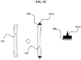
- forming the first layer comprises providing a preshaped structural element for fastening the ophthalmic lens to an eyewear frame, wherein the preshaped structural element comprises the coating material effective to reduce a reflection caused by a profile of the edge surface, and disposing the preshaped structural element on the edge surface of the ophthalmic lens.
- the structural element may be formed prior to the disposing.
- the structural element may be shaped prior to the disposing, otherwise termed herein as "preshaping" or "preshaped".
- disposing the preshaped structural element may further comprise applying an adhesive to one or both the preshaped structural element and the edge surface of the ophthalmic lens to attach the preshaped structural element to the edge surface of the ophthalmic lens.
- suitable adhesive may include, but are not limited to, an epoxy, polyurethane, silicone, and acrylate-based adhesive. Colorants may be incorporated into the adhesive for cosmetic purposes, and/or to further reduce reflection caused by a profile of the edge surface.
- disposing the preshaped structural element may be carried out directly without applying an adhesive to one or both the preshaped structural element and the edge surface of the ophthalmic lens to attach the preshaped structural element to the edge surface of the ophthalmic lens, since the first layer already provides an adhesive function.
- the method disclosed herein may further comprise forming a second layer on the first layer, wherein the second layer defines a structural element for fastening the ophthalmic lens to an eyewear frame.
- the first layer comprising the coating material effective to reduce a reflection caused by a profile of the edge surface may or may not define a structural element such as a lens bevel for fastening the ophthalmic lens to an eyewear frame, since the second layer defines such a structural element.
- the first layer may be in the form of a planar layer having a substantially uniform thickness throughout the layer.
- forming the second layer comprises disposing a substance for forming the second layer on the first layer, and shaping the disposed substance to define the structural element for fastening the ophthalmic lens to an eyewear frame. Methods described above for disposing the first layer and shaping the disposed substance may similarly be used for disposing the second layer.
- forming the second layer comprises disposing a substance for forming the second layer on the first layer, wherein the disposing is carried out in such manner as to shape the disposed substance to define the structural element for fastening the ophthalmic lens to an eyewear frame.
- Methods described above for disposing the first layer in such manner as to shape the material disposed to define the structural element for fastening the ophthalmic lens to an eyewear frame such as extrusion and an additive manufacturing process such as 3D printing and FDM, may similarly be used for disposing the second layer.
- forming the second layer comprises providing a preshaped structural element for fastening the ophthalmic lens to an eyewear frame, wherein the preshaped structural element comprises a substance for forming the second layer, and disposing the preshaped structural element on the first layer.
- the preshaped structural element comprises a substance for forming the second layer
- Disposing the preshaped structural element may further comprise applying an adhesive to one or both the preshaped structural element and the first layer to attach the preshaped structural element to the first layer. Methods described above for disposing the preshaped structural element as the first layer and for attaching the preshaped structural element to the underlying surface may similarly be used for disposing the second layer.
- the second layer may be formed from a material selected from the group consisting of an epoxy, a polyester, a polyurethane, acrylonitrile butadiene styrene, an acrylate, cellulose acetate butyrate, a copolymer thereof, and a combination thereof.
- the second layer may in some embodiments comprise or consist of an adhesive.
- suitable adhesive may include, but are not limited to, epoxy, polyurethane, silicone, and acrylate-based adhesive.
- the structural element defined by the second layer may assume a free-form structure or a shape that is at least substantially flat, so as to maximise contact or contact area between the second layer and the eyewear frame, for fastening the ophthalmic lens to the eyewear frame.
- the second layer does not comprise an adhesive.
- the structural element defined by the second layer may have a suitable shape, for example a regular shape such as a cube, a sphere, a hemisphere, or a polyhedron such as a pyramid or a tetrahedron, to allow coupling with a complementary shape on an eyewear frame so as to allow fastening of the ophthalmic lens to an eyewear frame.
- the second layer may be formed from a material which is the same as or different from the first layer. In some embodiments, the second layer is disposed directly on the first layer. In various embodiments, the second layer, if present, is formed from a material different from the first layer.
- the first layer may comprise or consist of carbon black as an opacity agent dispersed in polyurethane as a matrix material, whereas the second layer may comprise or consist of an epoxy.
- the second layer is present and the first layer is planar.
- Various embodiments refer in a third aspect to an eyewear comprising an eyewear frame and an ophthalmic lens according to the first aspect.
- the ophthalmic lens disclosed herein may be an augmented reality (AR) lens or a virtual reality (VR) lens.
- the eyewear may be in the form of an AR or VR device comprising an ophthalmic lens disclosed herein, whereby the ophthalmic lens may be configured with or without power correction. Due to presence of artificial light sources which are used to generate imaginary images in the AR/VR devices, reflections are accentuated in these devices.
- an ophthalmic lens disclosed herein allows further reduction of reflections off the edge surface of the lens as compared to conventional lenses.
- ophthalmic lens with planar edge surfaces meant for use in frameless eyewear may be converted using a method disclosed herein into an opththalmic lens comprising a structural element for fastening into an eyewear frame, and which may accordingly be used in an eyewear comprising an eyewear frame.
- Various embodiments of the present disclosure describe an enhanced configuration of lens with efficient suppression of myopia rings.
- the innovation outlined herein provides a lens configuration that allows ease in providing color edge coating to suppress myopia rings efficiently. It also helps to minimize myopia ring appearance due to flat edge surface.
- Various embodiments described herein may be used for any lens material and any frame shape and size. It may be used for prescription lenses as well as sunwear. It may be implemented at manufacturing plants, as well as prescription labs whereby customized production according to prescription order from the wearer may be carried out. For example, when making progressive lens, the manufacturing plant may provide semi-finished lens as a blank to the prescription lab, which may then carry out machining on the specific power distribution of the lens according to a prescription order from the wearer.
- Suppression of myopia rings in colored-edge-lenses may be effected by providing a colored coating on edged surface of the lenses.
- the edged surface of a lens comprises a lens bevel structure and/or other possible geometries, they introduce various surfaces onto the edged surface and thus provide areas of light reflections at various angles and directions. Irrespective of the optical powers of the lenses, these additional reflections from the bevel surfaces add up the appearance of the myopia rings.
- myopia rings may be suppressed by providing a light absorbing colored coating on the lens edge which covers all the reflecting surfaces making them non-reflective
- the bevel geometries may render the coating application complex and often lead to non-uniform thickness of coating. This may in turn lead to irregular suppression of myopia rings across the edge surface of a lens.
- the present innovation proposes to edge the lens without bevel, keeping the edged surface flat.
- a coating material may be applied onto a flat edged surface with greater ease (compared to lens edge with bevel), leading to highly uniform coating layer without or with a lower incidence of defects.
- the use of a flat edge surface may enhance myopia rings suppression in 2 ways:
- the flat surface may allow highly uniform layer of coating material with uniform thickness, reducing the defects and thus enhancing myopia ring suppression.
- the bevel geometry may be formed onto the colored edged surface of lens using either color or transparent polymeric material along the rim with predefined shape and size.
- the bevel structure may be formed by polymers, elastomers, UV curing and/or thermal curing polymeric systems. Some examples of such materials are epoxy, polyurethane, silicones, acrylates, etc.
- the bevel structure may be formed by 'forming material', which may be colored or colorless, made of similar chemistry as the coating material (such as polyurethane), or it may be of any other chemistry such as epoxy, silicone, and acrylates.
- the bevel structure may be formed by depositing the 'forming material' onto the coated edge in the form of highly viscous / semi-solid strips in shape of a bevel. The strips may be 'shaped-up' in bevel by using a finishing tool with a geometry complementary to the bevel shape.
- the forming material may be solidified by curing, either with UV, IR or heat energy.
- an opaque structure that comprises of a suitable adhesive/ locking mechanism on one end to secure itself firmly onto the flat edged surface and which has also a bevel (and other necessary geometry) on the other end to secure itself to the frame, may also be provided to render the edged surface opaque.
- the adhesive may be selected from the family of epoxies and acrylates (in particular cyanoacrylates for fast bonding).
- the adhesive may also contain colorants to either absorb reflection or to introduce suitable colour for cosmetic purposes (e.g frame-colour matching).
- the materials for the bevel structure may be selected from the family of epoxies, polyesters, polyurethanes and ABS. Polymer extrusion and 3D printing may be employed to shape the structure.
- the bevel structure could be made available in the finished ring form (more rigid materials like ABS could be used) or it could be supplied in the form of long continuous strip (more flexible materials like PU to be used).
Landscapes
- Chemical & Material Sciences (AREA)
- Physics & Mathematics (AREA)
- Engineering & Computer Science (AREA)
- Optics & Photonics (AREA)
- Health & Medical Sciences (AREA)
- General Physics & Mathematics (AREA)
- Ophthalmology & Optometry (AREA)
- Wood Science & Technology (AREA)
- Life Sciences & Earth Sciences (AREA)
- Materials Engineering (AREA)
- Organic Chemistry (AREA)
- Inorganic Chemistry (AREA)
- General Health & Medical Sciences (AREA)
- Chemical Kinetics & Catalysis (AREA)
- Manufacturing & Machinery (AREA)
- Mechanical Engineering (AREA)
- Eyeglasses (AREA)
Priority Applications (4)
| Application Number | Priority Date | Filing Date | Title |
|---|---|---|---|
| EP19306140.5A EP3796053A1 (de) | 2019-09-19 | 2019-09-19 | Ophthalmische linse, herstellungsverfahren dafür und brille mit der ophthalmischen linse |
| PCT/EP2020/076184 WO2021053191A1 (en) | 2019-09-19 | 2020-09-18 | Ophthalmic lens, method of manufacturing thereof, and eyewear comprising the ophthalmic lens |
| CN202080065649.5A CN114521244A (zh) | 2019-09-19 | 2020-09-18 | 眼科镜片、其制造方法以及包括眼科镜片的眼睛配戴物 |
| US17/761,875 US20220365365A1 (en) | 2019-09-19 | 2020-09-18 | Ophthalmic lens, method of manufacturing thereof, and eyewear comprising the ophthalmic lens |
Applications Claiming Priority (1)
| Application Number | Priority Date | Filing Date | Title |
|---|---|---|---|
| EP19306140.5A EP3796053A1 (de) | 2019-09-19 | 2019-09-19 | Ophthalmische linse, herstellungsverfahren dafür und brille mit der ophthalmischen linse |
Publications (1)
| Publication Number | Publication Date |
|---|---|
| EP3796053A1 true EP3796053A1 (de) | 2021-03-24 |
Family
ID=68242592
Family Applications (1)
| Application Number | Title | Priority Date | Filing Date |
|---|---|---|---|
| EP19306140.5A Pending EP3796053A1 (de) | 2019-09-19 | 2019-09-19 | Ophthalmische linse, herstellungsverfahren dafür und brille mit der ophthalmischen linse |
Country Status (4)
| Country | Link |
|---|---|
| US (1) | US20220365365A1 (de) |
| EP (1) | EP3796053A1 (de) |
| CN (1) | CN114521244A (de) |
| WO (1) | WO2021053191A1 (de) |
Cited By (1)
| Publication number | Priority date | Publication date | Assignee | Title |
|---|---|---|---|---|
| WO2023096913A1 (en) * | 2021-11-24 | 2023-06-01 | Satisloh Ag | Device (system) and method for determining edge profile of lens |
Citations (5)
| Publication number | Priority date | Publication date | Assignee | Title |
|---|---|---|---|---|
| GB191207033A (en) * | 1912-03-22 | 1912-08-01 | Xenophon Pappa Moschou | Improvements in Spectacles and Eye Glasses. |
| US5007977A (en) * | 1988-03-17 | 1991-04-16 | Wernicke & Co. Gmbh | Method and apparatus for applying a strip to the planar contour-prepared edge of a rotating lens |
| US20020008847A1 (en) * | 2000-07-21 | 2002-01-24 | Abby Ayoub | Optical lens coating and method |
| FR2828564A1 (fr) * | 2001-08-08 | 2003-02-14 | Olivier Bataillard | Procede d'elimination de l'irisation concentrique myopique pour lunettes de vue |
| GB2564656A (en) * | 2017-07-17 | 2019-01-23 | Shuabe Khan Mohammed | A spectacle lens |
Family Cites Families (3)
| Publication number | Priority date | Publication date | Assignee | Title |
|---|---|---|---|---|
| AUPR056300A0 (en) * | 2000-09-29 | 2000-10-26 | Sola International Holdings Ltd | Edge coated ophthalmic lens |
| US6886937B2 (en) * | 2003-06-20 | 2005-05-03 | Vision - Ease Lens, Inc. | Ophthalmic lens with graded interference coating |
| EP3153909A1 (de) * | 2015-10-09 | 2017-04-12 | ESSILOR INTERNATIONAL (Compagnie Générale d'Optique) | Verfahren zur bestimmung eines verwendungsindexwerts für monofokale ophthalmische linse |
-
2019
- 2019-09-19 EP EP19306140.5A patent/EP3796053A1/de active Pending
-
2020
- 2020-09-18 CN CN202080065649.5A patent/CN114521244A/zh active Pending
- 2020-09-18 US US17/761,875 patent/US20220365365A1/en active Pending
- 2020-09-18 WO PCT/EP2020/076184 patent/WO2021053191A1/en active Application Filing
Patent Citations (5)
| Publication number | Priority date | Publication date | Assignee | Title |
|---|---|---|---|---|
| GB191207033A (en) * | 1912-03-22 | 1912-08-01 | Xenophon Pappa Moschou | Improvements in Spectacles and Eye Glasses. |
| US5007977A (en) * | 1988-03-17 | 1991-04-16 | Wernicke & Co. Gmbh | Method and apparatus for applying a strip to the planar contour-prepared edge of a rotating lens |
| US20020008847A1 (en) * | 2000-07-21 | 2002-01-24 | Abby Ayoub | Optical lens coating and method |
| FR2828564A1 (fr) * | 2001-08-08 | 2003-02-14 | Olivier Bataillard | Procede d'elimination de l'irisation concentrique myopique pour lunettes de vue |
| GB2564656A (en) * | 2017-07-17 | 2019-01-23 | Shuabe Khan Mohammed | A spectacle lens |
Cited By (1)
| Publication number | Priority date | Publication date | Assignee | Title |
|---|---|---|---|---|
| WO2023096913A1 (en) * | 2021-11-24 | 2023-06-01 | Satisloh Ag | Device (system) and method for determining edge profile of lens |
Also Published As
| Publication number | Publication date |
|---|---|
| WO2021053191A1 (en) | 2021-03-25 |
| CN114521244A (zh) | 2022-05-20 |
| US20220365365A1 (en) | 2022-11-17 |
Similar Documents
| Publication | Publication Date | Title |
|---|---|---|
| US5928718A (en) | Protective coating for reflective sunglasses | |
| US10520756B2 (en) | Laminated mirror lens | |
| AU2017301860B2 (en) | Ophthalmic lens in particular for sunglasses | |
| US11981098B2 (en) | Optical lens and method of coating an edge surface of an optical lens | |
| US20210009849A1 (en) | Eyewear comprising an ophthalmic lens having an edge coating | |
| CN111417892B (zh) | 具有可变透射镜片的眼镜 | |
| US20220365365A1 (en) | Ophthalmic lens, method of manufacturing thereof, and eyewear comprising the ophthalmic lens | |
| WO2017099800A1 (en) | Eyewear with reflective filters | |
| JP5523446B2 (ja) | 眼鏡用レンズ及びその製造方法 | |
| WO1999021048A1 (en) | Coated sunglass lens | |
| US11474381B2 (en) | Ophthalmic article | |
| CN216748305U (zh) | 一种具有复合tac材质镜片的眼镜 | |
| EP3838572A1 (de) | Brillenglas, brille mit dem brillenglas und verfahren zur beschichtung einer randfläche eines brillenglases | |
| CN206638911U (zh) | 一种多功能的镜片 | |
| EP4357115A1 (de) | Verfahren zur herstellung einer transparenten kunststofflinse mit eingebetteten dekorativen elementen | |
| EP3936927A1 (de) | Verfahren zum färben eines ophtalmischen artikels und dazugehöriger ophtalmischer artikel | |
| US20230027705A1 (en) | Anti-reflective coating for side reflection | |
| US20230204982A1 (en) | Eyewear with chroma enhancement | |
| CN217506293U (zh) | 一种可精准过滤有害蓝光的无色偏防蓝光镜片及眼镜 | |
| EP3907553A1 (de) | Brillenglas, die so konfiguriert ist, dass sie einen klaren und optional einen dunklen zustand aufweist | |
| WO2020216909A1 (en) | An eyewear and method of manufacturing an eyewear | |
| CA2285612A1 (en) | Coated sunglass lens | |
| AU9728998A (en) | Coated sunglass lens | |
| MXPA99009344A (en) | Coated sunglass lens |
Legal Events
| Date | Code | Title | Description |
|---|---|---|---|
| PUAI | Public reference made under article 153(3) epc to a published international application that has entered the european phase |
Free format text: ORIGINAL CODE: 0009012 |
|
| STAA | Information on the status of an ep patent application or granted ep patent |
Free format text: STATUS: THE APPLICATION HAS BEEN PUBLISHED |
|
| AK | Designated contracting states |
Kind code of ref document: A1 Designated state(s): AL AT BE BG CH CY CZ DE DK EE ES FI FR GB GR HR HU IE IS IT LI LT LU LV MC MK MT NL NO PL PT RO RS SE SI SK SM TR |
|
| AX | Request for extension of the european patent |
Extension state: BA ME |
|
| STAA | Information on the status of an ep patent application or granted ep patent |
Free format text: STATUS: REQUEST FOR EXAMINATION WAS MADE |
|
| 17P | Request for examination filed |
Effective date: 20210917 |
|
| RBV | Designated contracting states (corrected) |
Designated state(s): AL AT BE BG CH CY CZ DE DK EE ES FI FR GB GR HR HU IE IS IT LI LT LU LV MC MK MT NL NO PL PT RO RS SE SI SK SM TR |
|
| P01 | Opt-out of the competence of the unified patent court (upc) registered |
Effective date: 20230525 |