EP3795985A1 - Graphene precursor determination method, determination device and determination program - Google Patents
Graphene precursor determination method, determination device and determination program Download PDFInfo
- Publication number
- EP3795985A1 EP3795985A1 EP19804488.5A EP19804488A EP3795985A1 EP 3795985 A1 EP3795985 A1 EP 3795985A1 EP 19804488 A EP19804488 A EP 19804488A EP 3795985 A1 EP3795985 A1 EP 3795985A1
- Authority
- EP
- European Patent Office
- Prior art keywords
- raw material
- graphite
- crystal system
- graphite layer
- graphene
- Prior art date
- Legal status (The legal status is an assumption and is not a legal conclusion. Google has not performed a legal analysis and makes no representation as to the accuracy of the status listed.)
- Granted
Links
Images




Classifications
-
- G—PHYSICS
- G01—MEASURING; TESTING
- G01N—INVESTIGATING OR ANALYSING MATERIALS BY DETERMINING THEIR CHEMICAL OR PHYSICAL PROPERTIES
- G01N23/00—Investigating or analysing materials by the use of wave or particle radiation, e.g. X-rays or neutrons, not covered by groups G01N3/00 – G01N17/00, G01N21/00 or G01N22/00
- G01N23/20—Investigating or analysing materials by the use of wave or particle radiation, e.g. X-rays or neutrons, not covered by groups G01N3/00 – G01N17/00, G01N21/00 or G01N22/00 by using diffraction of the radiation by the materials, e.g. for investigating crystal structure; by using scattering of the radiation by the materials, e.g. for investigating non-crystalline materials; by using reflection of the radiation by the materials
- G01N23/2055—Analysing diffraction patterns
-
- C—CHEMISTRY; METALLURGY
- C01—INORGANIC CHEMISTRY
- C01B—NON-METALLIC ELEMENTS; COMPOUNDS THEREOF; METALLOIDS OR COMPOUNDS THEREOF NOT COVERED BY SUBCLASS C01C
- C01B32/00—Carbon; Compounds thereof
- C01B32/20—Graphite
-
- G—PHYSICS
- G01—MEASURING; TESTING
- G01N—INVESTIGATING OR ANALYSING MATERIALS BY DETERMINING THEIR CHEMICAL OR PHYSICAL PROPERTIES
- G01N2223/00—Investigating materials by wave or particle radiation
- G01N2223/05—Investigating materials by wave or particle radiation by diffraction, scatter or reflection
- G01N2223/056—Investigating materials by wave or particle radiation by diffraction, scatter or reflection diffraction
- G01N2223/0566—Investigating materials by wave or particle radiation by diffraction, scatter or reflection diffraction analysing diffraction pattern
-
- G—PHYSICS
- G01—MEASURING; TESTING
- G01N—INVESTIGATING OR ANALYSING MATERIALS BY DETERMINING THEIR CHEMICAL OR PHYSICAL PROPERTIES
- G01N2223/00—Investigating materials by wave or particle radiation
- G01N2223/30—Accessories, mechanical or electrical features
- G01N2223/345—Accessories, mechanical or electrical features mathematical transformations on beams or signals, e.g. Fourier
-
- G—PHYSICS
- G01—MEASURING; TESTING
- G01N—INVESTIGATING OR ANALYSING MATERIALS BY DETERMINING THEIR CHEMICAL OR PHYSICAL PROPERTIES
- G01N2223/00—Investigating materials by wave or particle radiation
- G01N2223/60—Specific applications or type of materials
- G01N2223/605—Specific applications or type of materials phases
-
- G—PHYSICS
- G01—MEASURING; TESTING
- G01N—INVESTIGATING OR ANALYSING MATERIALS BY DETERMINING THEIR CHEMICAL OR PHYSICAL PROPERTIES
- G01N33/00—Investigating or analysing materials by specific methods not covered by groups G01N1/00 - G01N31/00
- G01N33/24—Earth materials
Definitions
- the present invention relates to a distinguishing method of a graphene precursor with respect to graphite raw material in which a hexagonal crystal system graphite layer and a rhombohedral crystal system graphite layer are mixed, and to a distinguishing apparatus and a distinguishing program thereof.
- Graphene is a new carbon material that was discovered in 2004 by both Dr. Geim and Dr. Novosolv at University of Manchester in England. It was found out by the two of them that graphene is a material with extremely superior physical properties compared to a conventional material, graphene exhibited a 100 times or larger strength than steel; exhibited a heat conducting characteristic and an electrical property of 10 to 100 times metal; and further a complete barrier property of not passing through various materials such as gas, liquid, etc. since a plane crystal structure is very small; and so forth.
- Graphene is an ultrathin nano-carbon material, similar in thinness to a single atom thick. A specific crystal structure in which carbon atoms are bonded in a honeycomb shape to form a two-dimensional plane is provided, and thus the graphene exhibits very high electron mobility, and also exhibits excellent physical properties such as an optical property, a thermal property, a dynamic property and so forth. Accordingly, the research and development of graphene has been actively progressing as a material of the next generation. There are several methods of synthesizing graphene, one of which is a method of acquiring graphene from graphite that is also a material of pencil. Graphite is a material having three-dimensional structure where two-dimensional graphene is attached thereon in multiple layers, and thus the graphene can be obtained by peeling this off (Refer to Patent Document 1).
- An advantage of the method of peeling graphene off from graphite is that production cost can be largely reduced.
- CVD chemical vapor deposition method
- the productivity of the peeling method is obviously high.
- CVD is a method in which a substrate such as copper or the like is placed inside a vacuum chamber, and gas containing carbon as a material of graphene flows thereto.
- Graphene of a large area with high quality can be film-formed on a substrate, however cost becomes high due to use of a vacuum environment, and thus it costs tens of dollars to hundreds of dollars to prepare graphene of 1 m 2 , though depending on its quality.
- the crystal structure of graphite can be figured out by a method (X-ray diffraction) of examining a diffraction phenomenon generated by scattering or interference of X-rays when a sample is irradiated with the X-rays.
- An existence ratio of each crystal structure can be distinguished from integrated intensity ratios of respective peaks by a powder X-ray diffraction method performing peak resolution on the acquired profiles (Refer to Non-Patent Document 1).
- Patent Document 1 Re-publication of PCT International Publication No. 2016-038692
- Non-Patent Document 1 R. A. Young, "The Rietveld Method", International Union of Crystallography Oxford University Press 1995, p. 255 - 275
- FIGS. 7A and 7B are diagrams showing profiles of powder X-ray diffraction patterns, whose peaks are distinguishable and undistinguishable from the appearance thereof respectively. As shown in FIG. 7A , when the peak can be clearly distinguished from the appearance of the profile, the peak separation is able to be performed sufficiently by peak profile fitting.
- the powder X-ray diffraction pattern with respect to graphite raw material derived from natural graphite as shown in FIG. 7B , a gently-sloping mountain in which the profile appearance includes the entire angle range is shown, and thus there is a case where each peak is not distinguishable from the appearance. In such a case, no peak separation is enabled, even though simply applying the peak profile fitting thereto.
- the present invention has been made in view of such a situation, and it is an object to provide a distinguishing method of a graphene precursor, that surely enables peak separation by peak profile fitting with a powder X-ray diffraction pattern with respect to graphite raw material, and also provide a distinguishing apparatus and a distinguishing program thereof.
- the peak separation can be surely enabled using peak profile fitting by a powder X-ray diffraction pattern with respect to graphite raw material.
- the hexagonal crystal system graphite layer abundantly contained in natural graphite is very stable, and thus energy exceeding Van der Waals force between graphene layers is given to peel off graphene thereof. Then, the energy required for peeling off is inversely proportional to the cube of the thickness. Accordingly, graphene is peeled off by weak physical force such as ultrasonic wave or the like because of being very weak in the state of being thick where layers are countlessly stacked, however, very large energy is required when being peeled off from thin graphite in some degree.
- graphene precursor that is suitable therefor.
- the graphene precursor is graphite having a specific crystal structure, and in contrast, when performing a conventional peeling process (such as ultrasonic wave, supercriticality, high-pressure spraying, collision, grinding, oxidation, reduction, microwave (in ionic liquid), kneading and so forth), the productivity is improved by 2.5 million times in theoretical value, as an estimate, compared to producing graphene by a CVD method.
- the graphene precursor having lower crystallinity than that of conventional graphite is easy to be peeled off, and thus a large amount of high-concentration graphene can be produced without a concentration process required in the conventional peeling method.
- This technique enables mass production of graphene (an annual production capacity of 100 to 10,000 tons or more), and supplying sufficient materials also in fields of secondary battery, capacitor, resin, rubber composite, composite building materials and so forth for which relatively inexpensive nanomaterials (20 to 100 dollars per kg) is required. It appears that the material development utilizing graphene will be further accelerated from now on, and thus if the above-described method is standardized, it becomes further important to distinguish a graphene precursor for companies and institutions that supply the graphene precursor that is raw material thereof.
- That kind of graphene precursor is configured to contain a rhombohedral crystal system graphite layer 3RH at a fixed ratio or more to a hexagonal crystal system graphite layer 2H.
- the hexagonal crystal system can be anything comprising crystal structure of an almost hexagonal crystal, which may be a perfect hexagonal crystal; a hexagonal crystal whose crystal structure is partially deformed; or a hexagonal crystal whose part or all is distorted. The same applies to rhombohedral crystal system.
- FIGS. 1A and 1B are diagrams showing crystal structures of a hexagonal crystal system graphite layer 2H and a rhombohedral crystal system graphite layer 3RH in graphite, respectively. It is known that natural graphite is classified into three kinds of crystal structures: a hexagonal crystal system graphite layer, a rhombohedral crystal system graphite layer and disorder, by how layers are stacked. As shown in FIG. 1A , regarding the hexagonal crystal system graphite layer 2H, the layers are stacked in order of ABABAB ⁇ ⁇ to form a crystal structure, and as shown in FIG.
- the layers are stacked in order of ABCABCABC ⁇ ⁇ to form a crystal structure.
- the rhombohedral crystal system graphite layer 3RH is actually classified into a rhombohedral crystal, however as shown in FIG. 1B , it is regarded as forming a hexagonal crystal in a pseudo manner, thereby being represented by using an axis of a hexagonal crystal system (that is, any crystal system below is represented by using an a-axis, a b-axis and a c-axis.)
- the natural graphite has almost no rhombohedral crystal system graphite layer at the mining stage, however a ratio thereof is increased by being pulverized and the like at the purification stage, and thus the rhombohedral crystal system graphite layer is present in a natural graphite-based carbon material by around 14%.
- the ratio of the rhombohedral crystal system graphite layer can be increased by processing the natural graphite by physical force or heat, thereby further enhancing the ratio by using radio-wave force together.
- the integrated intensity of a peak in a powder X-ray diffraction pattern can be calculated by giving initial values (position, width, height and so forth) of the peak; setting a restricting condition so as to prevent divergence of parameters during being refined; and performing profile fitting. At this time, since a converging position of the parameters varies in accordance with setting of the initial values, it is required for calculating a precise integrated intensity to utilize proper initial values.
- graphite raw material contains two kinds of polymorphisms: a hexagonal crystal system graphite layer 2H and a rhombohedral crystal system graphite layer 3RH, however any of them is one obtained in a closed synthetic environment (production environment), and thus an interplanar spacing between graphene sheets is the same and a structure inside the graphene sheets is the same in any structure.
- the initial value at the peak position is determined so as to satisfy these two relationships above. Since the peak position is finally refined, there is no problem even if a value slightly shifted from a precise value is used as an initial value.
- the c-axis length may be obtained by calculation based on the peak position of a 002 plane appearing at approximately 26°.
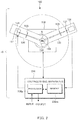
- FIG. 2 is a schematic diagram showing a configuration of a distinguishing system 10 of a graphene precursor.
- the distinguishing system 10 of a graphene precursor comprises an X-ray diffractometer 100 and a distinguishing apparatus 200.
- the X-ray diffractometer 100 and the distinguishing apparatus 200 are connected to each other in order to be able to transmit/receive information.
- the connection comprises information transmission with a storage medium, regardless of being wired and wireless.
- An X-ray diffractometer 100 is a device of measuring a powder X-ray diffraction pattern by irradiating X-rays of a specific wavelength such as CuK ⁇ 1 rays to a powder sample S.
- the X-ray diffractometer 100 is provided with a goniometer 110, and the goniometer 110 is provided with an X-ray source arm 120, a detector arm 130 and a sample stage 150.
- the X-ray source arm 120 supports an X-ray source 121
- the detector arm 130 supports an X-ray detector 131.
- the sample stage 150 provided at the center portion of the goniometer 110 supports a sample holder 155 to be able to be attached/detached.
- the powder sample S is filled inside a recess formed in the sample holder 155.
- Each of the X-ray source arm 120 and the detector arm 130 are independently rotatable with the same rotation axis as a center.
- the rotation axis is set so as to pass on the surface of the sample S supported by the goniometer 110.
- An X-ray generator 122 and a divergence slit 125 are fixed on the X-ray source arm 120.
- Other optical elements for example, a solar slit for parallelizing X-rays, a monochromator for taking characteristic X-rays out of X-rays including X-rays of various wavelengths, and so forth can also be arranged on the X-ray source arm 120, as needed.
- a filament that generates thermal electrons via current application and a target arranged to be opposed thereto are provided inside the X-ray generator 122.
- a region where the thermal electrons collide with the target becomes the X-ray source 121.
- a scattering slit 135, a receiving slit 137, and the X-ray detector 131 are provided on the detector arm 130.
- the scattering slit 135 prevents scattered X-rays from entering the X-ray detector 131.
- the receiving slit 137 prevents X-rays other than focused X-rays from entering the X-ray detector 131.
- the X-ray detector 131 is constituted of, for example, a zero-dimensional X-ray detector, and outputs a signal corresponding to the quantity of received X-rays, and an intensity detection circuit calculates the X-ray intensity based on the output signal.
- Either an one-dimensional X-ray detector or a two-dimensional X-ray detector may also be used as a X-ray detector.
- the X-ray diffractometer 100 can be any X-ray diffractometer as long as it is provided with a focusing optical system and able to measure a powder X-ray diffraction pattern, and utilized may be a configuration that is different from one described above, such as one in which the X-ray detector 131 is arranged on a Rowland circle, and so forth.
- the distinguishing apparatus 200 of a graphene precursor comprising a processor 200p and a memory 200m in hardware configuration is constituted from, for example, PC.
- the distinguishing apparatus 200 can calculate the integrated intensity of the peak for each crystal structure concerning graphite raw material in which the hexagonal crystal system graphite layer 2H and the rhombohedral crystal system graphite layer 3RH are mixed, based on the acquired powder X-ray diffraction pattern with a program stored in the memory 200m, that is executed by processor 200p. As a result of this, it enables a user to distinguish whether it is a graphene precursor or not.
- the distinguishing apparatus 200 receives input from a user and then outputs a processing result to the user.
- the input from the user is enabled by an operation device such as a keyboard, a mouse, a touch panel or the like, and can be displayed by an output device such as a display or the like.
- FIG. 3 is a block diagram showing a functional configuration of the distinguishing apparatus 200 of a graphene precursor.
- the distinguishing apparatus 200 comprises a data management section 210, an input section 220, a zero-point specification section 230, an integrated intensity calculation section 260, a fitting execution section 240, a determination section 270 and an output section 280.
- the data management section 210 stores and manages powder X-ray diffraction data received from the X-ray diffractometer 100 for each sample.
- the input section 220 receives input from an operation device such as a keyboard, a mouse, a touch panel or the like that is operated by a user. For example, when a sample is designated via the operation device by the user, the designation is received by the input section 220, and powder X-ray diffraction data of the designated sample is defined as a processing object by the data management section 210.
- the powder X-ray diffraction data indicates data obtained by a powder X-ray diffraction method; and the powder X-ray diffraction pattern or the profile indicates one in which the acquired data is recognized as a diffraction pattern or a profile; and although how to recognize it differs therefrom, substantial object data are identical thereto.
- the zero-point specification section 230 specifies a zero-point of a diffraction angle for the powder X-ray diffraction data of graphite raw material. It is preferred to specify a zero-point of a diffraction angle from a peak position of a diffracted beam by lattice planes in a c-axis direction common to the hexagonal crystal system graphite layer 2H and the rhombohedral crystal system graphite layer 3RH, by assuming that the c-axis length of the hexagonal crystal system graphite layer 2H is 2/3 times the c-axis length of the rhombohedral crystal system graphite layer 3RH in the graphite raw material.
- the zero-point of the diffraction angle can be specified from the peak position.
- the zero-point of the diffraction angle is preferably specified using peak positions of diffracted beams via a plurality of c-axis direction lattice planes. For example, when using two peak positions, simultaneous equations may be solved. Further, when using three or more peak positions, regression analysis of a least-squares method or the like can be used. In this manner, the zero-point of the diffraction angle is able to be precisely specified by eliminating errors. In addition, it is also possible to specify the zero-point by using a single peak position, and in this case, it is possible to suppress the influence of errors to be small by using a high-order peak.
- the integrated intensity calculation section 260 calculates the peak positions specific to the hexagonal crystal system graphite layer 2H and the rhombohedral crystal system graphite layer 3RH from the specified zero-point, by assuming that the a-axis and b-axis lengths of the hexagonal crystal system graphite layer 2H in graphite raw material are equal to the a-axis and b-axis lengths of the rhombohedral crystal system graphite layer 3RH therein, respectively; and the c-axis length of the hexagonal crystal system graphite layer 2H is 2/3 times the c-axis length of the rhombohedral crystal system graphite layer 3RH.
- the peak separation is surely enabled by a powder X-ray diffraction pattern with respect to graphite raw material.
- ratios of the rhombohedral crystal system graphite layer 3RH and the hexagonal crystal system graphite layer 2H in the graphite raw material can be certainly measured, and thus it can be accurately and precisely determined whether the graphite raw material is a graphene precursor or not. By doing this, it becomes possible to produce graphene at low cost by using a graphene peeling method.
- the integrated intensity calculation section 260 calculates an integrated intensity at the calculated peak position, based on the result obtained by the fitting execution section 240.
- a function whose peak is represented, that corresponds to an X-ray diffraction peak based on a given initial value is subjected to fitting by the fitting execution section 240.
- a relatively wide angle range can be subjected to fitting by the entire pattern decomposition, based on information of a crystal system and a lattice constant.
- fitting using a Lorentz function can be conducted.
- the determination section 270 determines whether graphite raw material is a graphene precursor or not, based on the calculated integrated intensity. In the determination step, preferably determined is whether or not a rate of an integrated intensity value of a 101 diffracted beam of the rhombohedral crystal system graphite layer 3RH to an integrated intensity value of a 101 diffracted beam of the hexagonal crystal system graphite layer 2H at the calculated peak positions is same as or higher than a predetermined value. In this manner, graphite raw material for which a graphene peeling method is applicable can be distinguished using an easily comparable integrated intensity value.
- the output section 280 determinably outputs whether the graphite raw material is a graphene precursor or not, based on the calculated integrated intensity. For example, the integrated intensity value P3 of the 101 diffracted beam of the rhombohedral crystal system graphite layer 3RH and the integrated intensity value P4 of the 101 diffracted beam of the hexagonal crystal system graphite layer 2H, respectively, can be displayed on a display by the output section 280 to be able to be compared. Further, the output section 280 may display the above-described rate P3/(P3 + P4) of the integrated intensities. In this case, user himself/herself determines whether the sample is a graphene precursor or not with displaying as a determination material. On the other hand, the output section 280 may display the result from which whether the sample is a graphene precursor or not is distinguished by the determination section 270, and thus in that case, the user does not have a load of distinguishing.
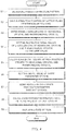
- FIG. 4 is a flowchart showing a distinguishing method of a graphene precursor. The explanation is made from a stage of preparing powder X-ray diffraction data, so as to be easily understood.
- graphite raw material is prepared.
- the graphite raw material used as a graphene precursor can be produced by a processing by radio-wave force and a processing by physical force in vacuum or air. That is, a graphite system carbon material more abundantly containing the rhombohedral crystal system graphite layer 3RH can be obtained by using the processing by the radio-wave force such as microwave, millimeter wave, plasma, electromagnetic induction heating (IH), magnetic field or the like, and the processing by the physical force such as ball mill, jet mill, centrifugal force, supercriticality or the like together in vacuum or air for a natural graphite material. It is preferred to apply the operations by the radio-wave force and the physical force are preferably applied thereto at the same time, however the radio-wave force and the physical force may be alternately applied thereto at each of predetermined intervals.
- the radio-wave force and the physical force may be alternately applied thereto at each of predetermined intervals.
- FIGS. 5A and 5B are graphs schematically showing powder X-ray diffraction pattern profiles of graphite raw material with respect to a 2 ⁇ of 0 to 90° and a 2 ⁇ of 40 to 45°, respectively.
- FIG. 5B is a graph obtained by enlarging the inside of a dashed line in FIG. 5A . According to the actual measurement, peaks are hardly distinguishable as shown in FIGS. 5A and 5B , however schematic graphs are used to be easily understood.
- the peak positions of 002, 004 and 006 diffracted beams of graphite are calculated by the entire pattern decomposition (step S2).
- the entire pattern decomposition is a method of performing profile fitting in a wide angle range, based on information of a crystal system and a lattice constant.
- respective c-axis lengths of the hexagonal crystal system graphite layer 2H and the rhombohedral crystal system graphite layer 3RH in graphite are determined (step S3), and the zero-point of 2 ⁇ is specified.
- respective initial values of the a-axis lengths of the hexagonal crystal system graphite layer 2H and the rhombohedral crystal system graphite layer 3RH in graphite are set to the same value (step S4).
- the initial values at four peak positions in a 2 ⁇ of 42 to 46° are calculated, based on the initial values of the hexagonal crystal system graphite layer 2H and the rhombohedral crystal system graphite layer 3RH in graphite (step S5). At this time, it is preferred that data in a 2 ⁇ of 40 to 50° is cut out from the viewpoint of processing efficiency. Further, respective initial values of shape parameters of four peaks are set (step S6).
- Profile fitting is performed in optimal order so as not to prevent each parameter from diverging, and each parameter is refined (step S7).
- An integrated intensity rate Rate (3RH) P3/(P3 + P4) of respective 101 peaks of the rhombohedral crystal system graphite layer 3RH and the hexagonal crystal system graphite layer 2H in graphite, obtained in this manner, is calculated (step S8). Then, a value of a rate of the acquired two peaks, Rate (3RH), is displayed (step S9).
- step S7 profile fitting for four peaks is performed in the following step. That is, scale factors are refined, and FWHMs (full widths at half maximum) of P2 and P3 are refined. At this time, it is preferred that respective FWHMs of P4 and P5 each are the same value as that of P3. Then, respective peak positions of P2 to P5 are refined. Further, a series of operations in steps S2 to S9 described above can be performed by executing a program.
- FIG. 6 is a diagram showing a table that shows experimental results of each sample. Each sample used was provided by Graphene Platform Corporation, and the data of the provider are shown as reference values.
- Rate (3RH) was able to be calculated accurately even from a powder X-ray diffraction pattern from which four peaks to be separated cannot be identified at all, from the measurement to the analysis in an automatic manner.
- measurement values of Rate (3RH) close to approximately a reference value were obtained.
- the Lorentz function is used in the above-described Example, however profile fitting is enabled even by using an FP (Fundamental Parameter) method.
Landscapes
- Chemical & Material Sciences (AREA)
- Life Sciences & Earth Sciences (AREA)
- Organic Chemistry (AREA)
- Health & Medical Sciences (AREA)
- Biochemistry (AREA)
- Geology (AREA)
- Crystallography & Structural Chemistry (AREA)
- Physics & Mathematics (AREA)
- General Life Sciences & Earth Sciences (AREA)
- Analytical Chemistry (AREA)
- Inorganic Chemistry (AREA)
- General Health & Medical Sciences (AREA)
- General Physics & Mathematics (AREA)
- Immunology (AREA)
- Pathology (AREA)
- Analysing Materials By The Use Of Radiation (AREA)
- Carbon And Carbon Compounds (AREA)
Abstract
Description
- The present invention relates to a distinguishing method of a graphene precursor with respect to graphite raw material in which a hexagonal crystal system graphite layer and a rhombohedral crystal system graphite layer are mixed, and to a distinguishing apparatus and a distinguishing program thereof.
- Graphene is a new carbon material that was discovered in 2004 by both Dr. Geim and Dr. Novosolv at University of Manchester in England. It was found out by the two of them that graphene is a material with extremely superior physical properties compared to a conventional material, graphene exhibited a 100 times or larger strength than steel; exhibited a heat conducting characteristic and an electrical property of 10 to 100 times metal; and further a complete barrier property of not passing through various materials such as gas, liquid, etc. since a plane crystal structure is very small; and so forth.
- Through this great discovery, Nobel Prize in Physics was awarded jointly to the two of them in 2010, just 6 years after the discovery in breaking of the custom of Nobel Prize. Then, the research toward the next generation on subjects such as graphene-based semiconductors, communication elements, electronic devices, batteries and so forth has been actively progressing, and in Europe and America, the 21st century has become so far as to be called "the age of Graphene Valley" in parody of Silicon Valley in California, USA, that has been developed from the late 20th century with high performance of silicon semiconductors.
- Graphene is an ultrathin nano-carbon material, similar in thinness to a single atom thick. A specific crystal structure in which carbon atoms are bonded in a honeycomb shape to form a two-dimensional plane is provided, and thus the graphene exhibits very high electron mobility, and also exhibits excellent physical properties such as an optical property, a thermal property, a dynamic property and so forth. Accordingly, the research and development of graphene has been actively progressing as a material of the next generation. There are several methods of synthesizing graphene, one of which is a method of acquiring graphene from graphite that is also a material of pencil. Graphite is a material having three-dimensional structure where two-dimensional graphene is attached thereon in multiple layers, and thus the graphene can be obtained by peeling this off (Refer to Patent Document 1).
- An advantage of the method of peeling graphene off from graphite is that production cost can be largely reduced. In comparison to CVD (chemical vapor deposition method) as a major graphene preparation method other than the peeling method, the productivity of the peeling method is obviously high. CVD is a method in which a substrate such as copper or the like is placed inside a vacuum chamber, and gas containing carbon as a material of graphene flows thereto. Graphene of a large area with high quality can be film-formed on a substrate, however cost becomes high due to use of a vacuum environment, and thus it costs tens of dollars to hundreds of dollars to prepare graphene of 1 m2, though depending on its quality. On the other hand, according to the peeling method, at the same cost of tens of dollars to hundreds of dollars, graphene of a weight of approximately 1 kg can be obtained. Since graphene is ultrathin and ultralight, and its surface area per unit weight is a huge value of approximately 2500 m2/g, a weight of 1 kg thereof is equivalent to CVD graphene with an area of 2,500,000 m2, film-formed on a substrate. That is, if a comparison is made in weight, there is a significant, 2.5 million-fold difference between CVD and the peeling method in terms of cost.
- On the other hand, the crystal structure of graphite can be figured out by a method (X-ray diffraction) of examining a diffraction phenomenon generated by scattering or interference of X-rays when a sample is irradiated with the X-rays. An existence ratio of each crystal structure can be distinguished from integrated intensity ratios of respective peaks by a powder X-ray diffraction method performing peak resolution on the acquired profiles (Refer to Non-Patent Document 1).
- Patent Document 1: Re-publication of PCT International Publication No.
2016-038692 - Non-Patent Document 1: R. A. Young, "The Rietveld Method", International Union of Crystallography Oxford University Press 1995, p. 255 - 275
- As to graphene produced by CVD, it is estimated that small-quantity production for high-value-added applications is carried out from now on. However, other than such applications, it appears that it is certain that graphene is mass-produced for various industrial applications by the peeling method.
- In this case, regarding profiles via the powder X-ray diffraction method, obtained from graphite raw material, it becomes important to evaluate suitability as a graphene precursor by distinguishing an existence ratio of each crystal structure from integrated intensities of two peaks in the vicinity of a diffraction angle 2θ of 42 to 46°.
-
FIGS. 7A and 7B are diagrams showing profiles of powder X-ray diffraction patterns, whose peaks are distinguishable and undistinguishable from the appearance thereof respectively. As shown inFIG. 7A , when the peak can be clearly distinguished from the appearance of the profile, the peak separation is able to be performed sufficiently by peak profile fitting. - However, according to, for example, the powder X-ray diffraction pattern with respect to graphite raw material derived from natural graphite, as shown in
FIG. 7B , a gently-sloping mountain in which the profile appearance includes the entire angle range is shown, and thus there is a case where each peak is not distinguishable from the appearance. In such a case, no peak separation is enabled, even though simply applying the peak profile fitting thereto. - The present invention has been made in view of such a situation, and it is an object to provide a distinguishing method of a graphene precursor, that surely enables peak separation by peak profile fitting with a powder X-ray diffraction pattern with respect to graphite raw material, and also provide a distinguishing apparatus and a distinguishing program thereof.
-
- (1) In order to achieve the above-described object, it is a feature that the distinguishing method of a graphene precursor according to the present invention is a distinguishing method of a graphene precursor with respect to graphite raw material in which a hexagonal crystal system graphite layer and a rhombohedral crystal system graphite layer are mixed, the method comprising the steps of specifying a zero-point of a diffraction angle for powder X-ray diffraction data of the graphite raw material; calculating peak positions specific to the hexagonal crystal system graphite layer and the rhombohedral crystal system graphite layer from the specified zero-point, by assuming that an interplanar spacing between graphene sheets forming the graphite raw material is the same in any graphite layer mixed in the graphite raw material and that a crystal structure inside the graphene sheets is the same in any graphite layer mixed in the graphite raw material; calculating integrated intensities at the calculated peak positions; and determining whether or not the graphite raw material is a graphene precursor based on the calculated integrated intensities.
In this manner, the peak separation can be surely enabled by a powder X-ray diffraction pattern with respect to graphite raw material. As a result of this, a ratio of the hexagonal crystal system graphite layer and the rhombohedral crystal system graphite layer in the graphite raw material can be measured accurately, and thus it can be accurately and precisely distinguished whether or the graphite raw material is a graphene precursor or not. Then, it becomes possible to produce graphene at low cost by using the peeling method. - (2) Further, it is a feature that the distinguishing method of a graphene precursor according to the present invention is the method, wherein in the step of specifying the zero-point of the diffraction angle, a peak position of a diffracted beam with the graphene sheets as lattice planes is used, by assuming that the interplanar spacing of the graphene sheet that forms the graphite raw material is the same in any structure mixed in the graphite raw material. In this manner, the zero-point of the diffraction angle can be specified from the peak position.
- (3) Further, it is a feature that the distinguishing method of a graphene precursor according to the present invention is the method, wherein the peak position of the diffracted beam with a plurality of the graphene sheets as the lattice planes is used in the step of specifying the zero-point of the diffraction angle. In this manner, the zero-point of the diffraction angle can be accurately specified by eliminating errors.
- (4) Further, it is a feature that the distinguishing method of a graphene precursor according to the present invention is the method, wherein in the step of distinguishing, it is distinguished whether or not a rate of an integrated intensity value of a 101 diffracted beam of the hexagonal crystal system graphite layer to an integrated intensity value of a 101 diffracted beam of the rhombohedral crystal system graphite layer at the calculated peak positions is same as or higher than a predetermined value. In this manner, the graphite raw material for which a graphene peeling method is applicable can be distinguished by using an integrated intensity values that is easy to be compared.
- (5) Further, it is a feature that the distinguishing method of a graphene precursor according to the present invention is the method, wherein it is distinguished whether or not P3/(P3 + P4) is 0.31 or more, when the calculated integrated intensity value of the 101 diffracted beam of the rhombohedral crystal system graphite layer represents P3, and the calculated integrated intensity value of the 101 diffracted beam of the hexagonal crystal system graphite layer represents P4. In this manner, the graphite raw material for which a graphene peeling method is applicable can be clearly distinguished by using specific numerical values.
- (6) Further, it is a feature that the distinguishing apparatus according to the present invention is a distinguishing apparatus of a graphene precursor with respect to graphite raw material in which a hexagonal crystal system graphite layer and a rhombohedral crystal system graphite layer are mixed, the apparatus comprising a zero-point specification section that specifies a zero-point of a diffraction angle for powder X-ray diffraction data of the graphite raw material; a peak position calculation section that calculates peak positions specific to the hexagonal crystal system graphite layer and the rhombohedral crystal system graphite layer from the specified zero-point, by assuming that an interplanar spacing between graphene sheets that form the graphite raw material is the same in any graphite layer mixed in the graphite raw material and that a crystal structure inside the graphene sheets is the same in any graphite layer mixed in the graphite raw material; an integrated intensity calculation section that calculates integrated intensities at the calculated peak positions; and an output section that outputs to be able to distinguish whether the graphite raw material is a graphene precursor or not, based on the calculated integrated intensities. In this manner, the peak separation is surely enabled by a powder X-ray diffraction pattern with respect to graphite raw material, and thus it can be distinguished whether the material is a graphene precursor or not.
- (7) Further, it is a feature that the distinguishing program according to the present invention is a program of distinguishing a graphene precursor with respect to graphite raw material in which a hexagonal crystal system graphite layer and a rhombohedral crystal system graphite layer are mixed, the program causing a computer to execute the processes of specifying a zero-point of a diffraction angle for powder X-ray diffraction data of the graphite raw material; calculating peak positions specific to the hexagonal crystal system graphite layer and the rhombohedral crystal system graphite layer from the specified zero-point, by assuming that an interplanar spacing between graphene sheets that form the graphite raw material is the same in any graphite layer mixed in the graphite raw material and that a crystal structure inside the graphene sheets is the same in any graphite layer mixed in the graphite raw material; calculating integrated intensities at the calculated peak positions; and outputting to be able to distinguish whether the graphite raw material is a graphene precursor or not, based on the calculated integrated intensities. In this manner, the peak separation is surely enabled by a powder X-ray diffraction pattern with respect to graphite raw material, and thus it can be distinguished that whether the material is a graphene precursor or not.
- According to the present invention, the peak separation can be surely enabled using peak profile fitting by a powder X-ray diffraction pattern with respect to graphite raw material.
-
-
FIGS. 1A and 1B are diagrams showing crystal structures of a hexagonal crystal system graphite layer and a rhombohedral crystal system graphite layer in graphite, respectively. -
FIG. 2 is a schematic diagram showing a configuration of a system of distinguishing a graphene precursor according to the present invention. -
FIG. 3 is a block diagram showing a functional configuration of a distinguishing apparatus of a graphene precursor according to the present invention. -
FIG. 4 is a flowchart showing a distinguishing method of a graphene precursor according to the present invention. -
FIGS. 5A and 5B are graphs schematically showing profiles having a powder X-ray diffraction pattern of graphite raw material with respect to 2θ of 0 to 90° and 2θ of 40 to 45°, respectively. -
FIG. 6 is a diagram showing a table that shows experimental results of each sample. -
FIGS. 7A and 7B are diagrams showing profiles of powder X-ray diffraction patterns, whose peaks are distinguishable and undistinguishable from the appearance thereof, respectively. - Next, embodiments of the present invention will be described referring to the drawings. In order to facilitate understanding of the description, reference number indicating the same constituent element is used as same and overlapping descriptions will be omitted in each drawing.
- The hexagonal crystal system graphite layer abundantly contained in natural graphite is very stable, and thus energy exceeding Van der Waals force between graphene layers is given to peel off graphene thereof. Then, the energy required for peeling off is inversely proportional to the cube of the thickness. Accordingly, graphene is peeled off by weak physical force such as ultrasonic wave or the like because of being very weak in the state of being thick where layers are countlessly stacked, however, very large energy is required when being peeled off from thin graphite in some degree.
- According to the peeling method by which graphene is peeled off from graphite to be produced, high efficiency can be further achieved by using "graphene precursor" that is suitable therefor. The graphene precursor is graphite having a specific crystal structure, and in contrast, when performing a conventional peeling process (such as ultrasonic wave, supercriticality, high-pressure spraying, collision, grinding, oxidation, reduction, microwave (in ionic liquid), kneading and so forth), the productivity is improved by 2.5 million times in theoretical value, as an estimate, compared to producing graphene by a CVD method.
- The graphene precursor having lower crystallinity than that of conventional graphite is easy to be peeled off, and thus a large amount of high-concentration graphene can be produced without a concentration process required in the conventional peeling method. This technique enables mass production of graphene (an annual production capacity of 100 to 10,000 tons or more), and supplying sufficient materials also in fields of secondary battery, capacitor, resin, rubber composite, composite building materials and so forth for which relatively inexpensive nanomaterials (20 to 100 dollars per kg) is required. It appears that the material development utilizing graphene will be further accelerated from now on, and thus if the above-described method is standardized, it becomes further important to distinguish a graphene precursor for companies and institutions that supply the graphene precursor that is raw material thereof.
- That kind of graphene precursor is configured to contain a rhombohedral crystal system graphite layer 3RH at a fixed ratio or more to a hexagonal crystal
system graphite layer 2H. In addition, the hexagonal crystal system can be anything comprising crystal structure of an almost hexagonal crystal, which may be a perfect hexagonal crystal; a hexagonal crystal whose crystal structure is partially deformed; or a hexagonal crystal whose part or all is distorted. The same applies to rhombohedral crystal system. -
FIGS. 1A and 1B are diagrams showing crystal structures of a hexagonal crystalsystem graphite layer 2H and a rhombohedral crystal system graphite layer 3RH in graphite, respectively. It is known that natural graphite is classified into three kinds of crystal structures: a hexagonal crystal system graphite layer, a rhombohedral crystal system graphite layer and disorder, by how layers are stacked. As shown inFIG. 1A , regarding the hexagonal crystalsystem graphite layer 2H, the layers are stacked in order of ABABAB · · to form a crystal structure, and as shown inFIG. 1B , regarding the rhombohedral crystal system graphite layer 3RH, the layers are stacked in order of ABCABCABC · · to form a crystal structure. Provided that the rhombohedral crystal system graphite layer 3RH is actually classified into a rhombohedral crystal, however as shown inFIG. 1B , it is regarded as forming a hexagonal crystal in a pseudo manner, thereby being represented by using an axis of a hexagonal crystal system (that is, any crystal system below is represented by using an a-axis, a b-axis and a c-axis.) - The natural graphite has almost no rhombohedral crystal system graphite layer at the mining stage, however a ratio thereof is increased by being pulverized and the like at the purification stage, and thus the rhombohedral crystal system graphite layer is present in a natural graphite-based carbon material by around 14%. The ratio of the rhombohedral crystal system graphite layer can be increased by processing the natural graphite by physical force or heat, thereby further enhancing the ratio by using radio-wave force together.
- The crystal structure of graphite can be figured out by a method (X-ray diffraction) of examining a diffraction phenomenon caused by scattering/interference of X-ray when X-ray is irradiated to a sample thereof. Accordingly, it can be determined whether the sample is a graphene precursor or not via checking whether the ratio of the rhombohedral crystal system graphite layer is same as or higher than a predetermined value, by comparing integrated intensities of peaks specific to respective crystal structures measured using X-ray diffraction. For example, this can be determined by the following numerical formula (1).

- P3: An integrated intensity value (2θ = 43 or a level thereof) of the rhombohedral crystal system graphite layer (101)
- P4: An integrated intensity value (2θ = 44 or a level thereof) of the hexagonal crystal system graphite layer (101)
- The integrated intensity of a peak in a powder X-ray diffraction pattern can be calculated by giving initial values (position, width, height and so forth) of the peak; setting a restricting condition so as to prevent divergence of parameters during being refined; and performing profile fitting. At this time, since a converging position of the parameters varies in accordance with setting of the initial values, it is required for calculating a precise integrated intensity to utilize proper initial values.
- Then, in the present invention, given is an assumption that "graphite raw material contains two kinds of polymorphisms: a hexagonal crystal
system graphite layer 2H and a rhombohedral crystal system graphite layer 3RH, however any of them is one obtained in a closed synthetic environment (production environment), and thus an interplanar spacing between graphene sheets is the same and a structure inside the graphene sheets is the same in any structure". - From those described above, the following relationships (1) and (2) are satisfied for lattice constants in two crystal structures.
- (1) The a-axis and b-axis lengths of 2H are equal to the a-axis and b-axis lengths of 3RH, respectively.
- (2) The c-axis length of 2H is 2/3 times the c-axis length of 3RH.
- The initial value at the peak position is determined so as to satisfy these two relationships above. Since the peak position is finally refined, there is no problem even if a value slightly shifted from a precise value is used as an initial value. In addition, the c-axis length may be obtained by calculation based on the peak position of a 002 plane appearing at approximately 26°.
- Next, the system capable of distinguishing a graphene precursor is explained, based on the assumption as described above.
FIG. 2 is a schematic diagram showing a configuration of a distinguishingsystem 10 of a graphene precursor. As shown inFIG. 2 , the distinguishingsystem 10 of a graphene precursor comprises anX-ray diffractometer 100 and adistinguishing apparatus 200. TheX-ray diffractometer 100 and thedistinguishing apparatus 200 are connected to each other in order to be able to transmit/receive information. The connection comprises information transmission with a storage medium, regardless of being wired and wireless. - An
X-ray diffractometer 100 is a device of measuring a powder X-ray diffraction pattern by irradiating X-rays of a specific wavelength such as CuKα1 rays to a powder sample S. TheX-ray diffractometer 100 is provided with agoniometer 110, and thegoniometer 110 is provided with anX-ray source arm 120, adetector arm 130 and asample stage 150. TheX-ray source arm 120 supports anX-ray source 121, and thedetector arm 130 supports anX-ray detector 131. - The
sample stage 150 provided at the center portion of thegoniometer 110 supports asample holder 155 to be able to be attached/detached. The powder sample S is filled inside a recess formed in thesample holder 155. - Each of the
X-ray source arm 120 and thedetector arm 130 are independently rotatable with the same rotation axis as a center. The rotation axis is set so as to pass on the surface of the sample S supported by thegoniometer 110. - An
X-ray generator 122 and adivergence slit 125 are fixed on theX-ray source arm 120. Other optical elements, for example, a solar slit for parallelizing X-rays, a monochromator for taking characteristic X-rays out of X-rays including X-rays of various wavelengths, and so forth can also be arranged on theX-ray source arm 120, as needed. - A filament that generates thermal electrons via current application and a target arranged to be opposed thereto are provided inside the
X-ray generator 122. A region where the thermal electrons collide with the target becomes theX-ray source 121. - A scattering slit 135, a receiving
slit 137, and theX-ray detector 131 are provided on thedetector arm 130. The scattering slit 135 prevents scattered X-rays from entering theX-ray detector 131. The receiving slit 137 prevents X-rays other than focused X-rays from entering theX-ray detector 131. TheX-ray detector 131 is constituted of, for example, a zero-dimensional X-ray detector, and outputs a signal corresponding to the quantity of received X-rays, and an intensity detection circuit calculates the X-ray intensity based on the output signal. Either an one-dimensional X-ray detector or a two-dimensional X-ray detector may also be used as a X-ray detector. In addition, theX-ray diffractometer 100 can be any X-ray diffractometer as long as it is provided with a focusing optical system and able to measure a powder X-ray diffraction pattern, and utilized may be a configuration that is different from one described above, such as one in which theX-ray detector 131 is arranged on a Rowland circle, and so forth. - The
distinguishing apparatus 200 of a graphene precursor comprising aprocessor 200p and amemory 200m in hardware configuration is constituted from, for example, PC. Thedistinguishing apparatus 200 can calculate the integrated intensity of the peak for each crystal structure concerning graphite raw material in which the hexagonal crystalsystem graphite layer 2H and the rhombohedral crystal system graphite layer 3RH are mixed, based on the acquired powder X-ray diffraction pattern with a program stored in thememory 200m, that is executed byprocessor 200p. As a result of this, it enables a user to distinguish whether it is a graphene precursor or not. - The
distinguishing apparatus 200 receives input from a user and then outputs a processing result to the user. The input from the user is enabled by an operation device such as a keyboard, a mouse, a touch panel or the like, and can be displayed by an output device such as a display or the like. -
FIG. 3 is a block diagram showing a functional configuration of thedistinguishing apparatus 200 of a graphene precursor. As shown inFIG. 3 , thedistinguishing apparatus 200 comprises adata management section 210, aninput section 220, a zero-point specification section 230, an integratedintensity calculation section 260, afitting execution section 240, adetermination section 270 and anoutput section 280. - The
data management section 210 stores and manages powder X-ray diffraction data received from theX-ray diffractometer 100 for each sample. Theinput section 220 receives input from an operation device such as a keyboard, a mouse, a touch panel or the like that is operated by a user. For example, when a sample is designated via the operation device by the user, the designation is received by theinput section 220, and powder X-ray diffraction data of the designated sample is defined as a processing object by thedata management section 210. In addition, the powder X-ray diffraction data indicates data obtained by a powder X-ray diffraction method; and the powder X-ray diffraction pattern or the profile indicates one in which the acquired data is recognized as a diffraction pattern or a profile; and although how to recognize it differs therefrom, substantial object data are identical thereto. - The zero-
point specification section 230 specifies a zero-point of a diffraction angle for the powder X-ray diffraction data of graphite raw material. It is preferred to specify a zero-point of a diffraction angle from a peak position of a diffracted beam by lattice planes in a c-axis direction common to the hexagonal crystalsystem graphite layer 2H and the rhombohedral crystal system graphite layer 3RH, by assuming that the c-axis length of the hexagonal crystalsystem graphite layer 2H is 2/3 times the c-axis length of the rhombohedral crystal system graphite layer 3RH in the graphite raw material. In this manner, the zero-point of the diffraction angle can be specified from the peak position. The zero-point of the diffraction angle is preferably specified using peak positions of diffracted beams via a plurality of c-axis direction lattice planes. For example, when using two peak positions, simultaneous equations may be solved. Further, when using three or more peak positions, regression analysis of a least-squares method or the like can be used. In this manner, the zero-point of the diffraction angle is able to be precisely specified by eliminating errors. In addition, it is also possible to specify the zero-point by using a single peak position, and in this case, it is possible to suppress the influence of errors to be small by using a high-order peak. - The integrated
intensity calculation section 260 calculates the peak positions specific to the hexagonal crystalsystem graphite layer 2H and the rhombohedral crystal system graphite layer 3RH from the specified zero-point, by assuming that the a-axis and b-axis lengths of the hexagonal crystalsystem graphite layer 2H in graphite raw material are equal to the a-axis and b-axis lengths of the rhombohedral crystal system graphite layer 3RH therein, respectively; and the c-axis length of the hexagonal crystalsystem graphite layer 2H is 2/3 times the c-axis length of the rhombohedral crystal system graphite layer 3RH. In this manner, the peak separation is surely enabled by a powder X-ray diffraction pattern with respect to graphite raw material. As a result of this, ratios of the rhombohedral crystal system graphite layer 3RH and the hexagonal crystalsystem graphite layer 2H in the graphite raw material can be certainly measured, and thus it can be accurately and precisely determined whether the graphite raw material is a graphene precursor or not. By doing this, it becomes possible to produce graphene at low cost by using a graphene peeling method. - Then, the integrated
intensity calculation section 260 calculates an integrated intensity at the calculated peak position, based on the result obtained by thefitting execution section 240. A function whose peak is represented, that corresponds to an X-ray diffraction peak based on a given initial value is subjected to fitting by thefitting execution section 240. For example, in the case where the peak position of the main peak is specified, a relatively wide angle range can be subjected to fitting by the entire pattern decomposition, based on information of a crystal system and a lattice constant. Further, in the case where the integrated intensity is calculated, fitting using a Lorentz function can be conducted. - The
determination section 270 determines whether graphite raw material is a graphene precursor or not, based on the calculated integrated intensity. In the determination step, preferably determined is whether or not a rate of an integrated intensity value of a 101 diffracted beam of the rhombohedral crystal system graphite layer 3RH to an integrated intensity value of a 101 diffracted beam of the hexagonal crystalsystem graphite layer 2H at the calculated peak positions is same as or higher than a predetermined value. In this manner, graphite raw material for which a graphene peeling method is applicable can be distinguished using an easily comparable integrated intensity value. - Specifically, it is preferred to determine whether or not P3/(P3 + P4) is 0.31 or more when the calculated integrated intensity value of the 101 diffracted beam of the rhombohedral crystal system graphite layer 3RH represents P3, and the calculated integrated intensity value of the 101 diffracted beam of the hexagonal crystal
system graphite layer 2H represents P4. In this manner, the graphite raw material for which a graphene peeling method is applicable can be clearly distinguished by using specific numerical values. - The
output section 280 determinably outputs whether the graphite raw material is a graphene precursor or not, based on the calculated integrated intensity. For example, the integrated intensity value P3 of the 101 diffracted beam of the rhombohedral crystal system graphite layer 3RH and the integrated intensity value P4 of the 101 diffracted beam of the hexagonal crystalsystem graphite layer 2H, respectively, can be displayed on a display by theoutput section 280 to be able to be compared. Further, theoutput section 280 may display the above-described rate P3/(P3 + P4) of the integrated intensities. In this case, user himself/herself determines whether the sample is a graphene precursor or not with displaying as a determination material. On the other hand, theoutput section 280 may display the result from which whether the sample is a graphene precursor or not is distinguished by thedetermination section 270, and thus in that case, the user does not have a load of distinguishing. - It can be determined whether graphite raw material is a graphene precursor or not by using the distinguishing
system 10 constituted as described above.FIG. 4 is a flowchart showing a distinguishing method of a graphene precursor. The explanation is made from a stage of preparing powder X-ray diffraction data, so as to be easily understood. - First, graphite raw material is prepared. The graphite raw material used as a graphene precursor can be produced by a processing by radio-wave force and a processing by physical force in vacuum or air. That is, a graphite system carbon material more abundantly containing the rhombohedral crystal system graphite layer 3RH can be obtained by using the processing by the radio-wave force such as microwave, millimeter wave, plasma, electromagnetic induction heating (IH), magnetic field or the like, and the processing by the physical force such as ball mill, jet mill, centrifugal force, supercriticality or the like together in vacuum or air for a natural graphite material. It is preferred to apply the operations by the radio-wave force and the physical force are preferably applied thereto at the same time, however the radio-wave force and the physical force may be alternately applied thereto at each of predetermined intervals.
- The powder X-ray diffraction pattern of graphite raw material prepared in this manner is measured (step S1). At that time, it is preferred to be measured up to a 2θ of 90° or more.
FIGS. 5A and 5B are graphs schematically showing powder X-ray diffraction pattern profiles of graphite raw material with respect to a 2θ of 0 to 90° and a 2θ of 40 to 45°, respectively.FIG. 5B is a graph obtained by enlarging the inside of a dashed line inFIG. 5A . According to the actual measurement, peaks are hardly distinguishable as shown inFIGS. 5A and 5B , however schematic graphs are used to be easily understood. - Based on the resulting powder X-ray diffraction pattern, the peak positions of 002, 004 and 006 diffracted beams of graphite are calculated by the entire pattern decomposition (step S2). The entire pattern decomposition is a method of performing profile fitting in a wide angle range, based on information of a crystal system and a lattice constant.
- In this manner, respective c-axis lengths of the hexagonal crystal
system graphite layer 2H and the rhombohedral crystal system graphite layer 3RH in graphite are determined (step S3), and the zero-point of 2θ is specified. Then, respective initial values of the a-axis lengths of the hexagonal crystalsystem graphite layer 2H and the rhombohedral crystal system graphite layer 3RH in graphite are set to the same value (step S4). The initial values at four peak positions in a 2θ of 42 to 46° are calculated, based on the initial values of the hexagonal crystalsystem graphite layer 2H and the rhombohedral crystal system graphite layer 3RH in graphite (step S5). At this time, it is preferred that data in a 2θ of 40 to 50° is cut out from the viewpoint of processing efficiency. Further, respective initial values of shape parameters of four peaks are set (step S6). - Profile fitting is performed in optimal order so as not to prevent each parameter from diverging, and each parameter is refined (step S7). An integrated intensity rate Rate (3RH) = P3/(P3 + P4) of respective 101 peaks of the rhombohedral crystal system graphite layer 3RH and the hexagonal crystal
system graphite layer 2H in graphite, obtained in this manner, is calculated (step S8). Then, a value of a rate of the acquired two peaks, Rate (3RH), is displayed (step S9). In addition, a peak representing the rhombohedral crystal system graphite layer 3RH, and a peak representing the hexagonal crystalsystem graphite layer 2H can be selected, however it is preferred to use P3 and P4. It is preferred that a value of Rate (3RH) = P3/(P3 + P4) is automatically displayed powder X-ray diffraction data of graphite raw material are specified. - In addition, according to the step S7, profile fitting for four peaks is performed in the following step. That is, scale factors are refined, and FWHMs (full widths at half maximum) of P2 and P3 are refined. At this time, it is preferred that respective FWHMs of P4 and P5 each are the same value as that of P3. Then, respective peak positions of P2 to P5 are refined. Further, a series of operations in steps S2 to S9 described above can be performed by executing a program.
- The sample data were measured using the above-described distinguishing method of a graphene precursor to find a value of Rate (3RH).
FIG. 6 is a diagram showing a table that shows experimental results of each sample. Each sample used was provided by Graphene Platform Corporation, and the data of the provider are shown as reference values. - According to profile fitting when finding Rate (3RH), initial values at peak positions were determined from some literature values (theoretical values of bonding distance) and 100 or more actual measurement data as a = b = 2.46 angstroms and c = 6.71 angstroms for 2H. Then, the values each at which only the FWHM of P2 is narrow were utilized as initial values in comparison with other peaks. This is because it is determined that there are many cases where only P2 is viewed in actual measurement data, and thus the narrow FWHM is often observable in comparison with three other peaks. Eventually, the FWHM of P2 is independently refined, and thus it is enough to be narrower than that of each of P3 to P5 and initial values do not have to be set smaller than necessary.
- In the case of distinguishing a graphene precursor, it appears that those having various crystallite sizes are mixed, from the viewpoint of properties of a graphite sample. In such a case, it appears that a precise fitting result is given by a Lorentz function. Thus, the Lorentz function was used as a profile function.
- In this manner, the value of Rate (3RH) was able to be calculated accurately even from a powder X-ray diffraction pattern from which four peaks to be separated cannot be identified at all, from the measurement to the analysis in an automatic manner. As shown in
FIG. 6 , measurement values of Rate (3RH) close to approximately a reference value were obtained. In addition, the Lorentz function is used in the above-described Example, however profile fitting is enabled even by using an FP (Fundamental Parameter) method. -
- 10
- Distinguishing system
- 100
- X-ray diffractometer
- 110
- Goniometer
- 120
- X-ray source arm
- 121
- X-ray source
- 122
- X-ray generator
- 125
- Divergence slit
- 130
- Detector arm
- 131
- X-ray detector
- 135
- Scattering slit
- 137
- Receiving slit
- 150
- Sample stage
- 155
- Sample holder
- 200
- Distinguishing apparatus
- 200m
- Memory
- 200p
- Processor
- 210
- Data management section
- 220
- Input section
- 230
- Zero-point specification section
- 240
- Fitting execution section
- 260
- Integrated intensity calculation section
- 270
- Determination section
- 280
- Output section
- S
- Sample
Claims (7)
- A distinguishing method of a graphene precursor with respect to graphite raw material in which a hexagonal crystal system graphite layer and a rhombohedral crystal system graphite layer are mixed, the method comprising the steps of:specifying a zero-point of a diffraction angle for powder X-ray diffraction data of the graphite raw material;calculating peak positions specific to the hexagonal crystal system graphite layer and the rhombohedral crystal system graphite layer from the specified zero-point, by assuming that an interplanar spacing between graphene sheets that form the graphite raw material is the same in any graphite layer mixed in the graphite raw material and that a crystal structure inside the graphene sheets is the same in any graphite layer mixed in the graphite raw material;calculating integrated intensities at the calculated peak positions; anddetermining whether the graphite raw material is a graphene precursor or not based on the calculated integrated intensities.
- The distinguishing method of a graphene precursor according to claim 1,
wherein in the step of specifying the zero-point of the diffraction angle, a peak position of a diffracted beam with the graphene sheets as lattice planes is used, by assuming that the interplanar spacing between the graphene sheets that form the graphite raw material is the same in any structure mixed in the graphite raw material. - The distinguishing method of a graphene precursor according to claim 2,
wherein the peak position of the diffracted beam with a plurality of the graphene sheets as the lattice planes is used in the step of specifying the zero-point of the diffraction angle. - The distinguishing method of a graphene precursor according to any one of claims 1 to 3,
wherein in the step of determining, whether or not a rate of an integrated intensity value of a 101 diffracted beam of the hexagonal crystal system graphite layer to an integrated intensity value of a 101 diffracted beam of the rhombohedral crystal system graphite layer at the calculated peak positions is the same as or higher than a predetermined value is determined. - The distinguishing method of a graphene precursor according to claim 4,
wherein it is determined whether or not P3/(P3 + P4) is 0.31 or more, when the calculated integrated intensity value of the 101 diffracted beam of the rhombohedral crystal system graphite layer represents P3, and the calculated integrated intensity value of the 101 diffracted beam of the hexagonal crystal system graphite layer represents P4. - A distinguishing apparatus of a graphene precursor with respect to graphite raw material in which a hexagonal crystal system graphite layer and a rhombohedral crystal system graphite layer are mixed, the apparatus comprising:a zero-point specification section that specifies a zero-point of a diffraction angle for powder X-ray diffraction data of the graphite raw material;a peak position calculation section that calculates peak positions specific to the hexagonal crystal system graphite layer and the rhombohedral crystal system graphite layer from the specified zero-point, by assuming that an interplanar spacing between graphene sheets that form the graphite raw material is the same in any graphite layer mixed in the graphite raw material and that a crystal structure inside the graphene sheets is the same in any graphite layer mixed in the graphite raw material;an integrated intensity calculation section that calculates integrated intensities at the calculated peak positions; andan output section that determinably outputs whether the graphite raw material is a graphene precursor or not based on the calculated integrated intensities.
- A distinguishing program of a graphene precursor with respect to graphite raw material in which a hexagonal crystal system graphite layer and a rhombohedral crystal system graphite layer are mixed, the program causing a computer to execute the processes of:specifying a zero-point of a diffraction angle for powder X-ray diffraction data of the graphite raw material;calculating peak positions specific to the hexagonal crystal system graphite layer and the rhombohedral crystal system graphite layer from the specified zero-point, by assuming that an interplanar spacing between graphene sheets that form the graphite raw material is the same in any graphite layer mixed in the graphite raw material and that a crystal structure inside the graphene sheets is the same in any graphite layer mixed in the graphite raw material;calculating integrated intensities at the calculated peak positions; anddeterminably outputting whether the graphite raw material is a graphene precursor or not based on the calculated integrated intensities.
Applications Claiming Priority (2)
| Application Number | Priority Date | Filing Date | Title |
|---|---|---|---|
| JP2018093324 | 2018-05-14 | ||
| PCT/JP2019/007216 WO2019220737A1 (en) | 2018-05-14 | 2019-02-26 | Graphene precursor determination method, determination device and determination program |
Publications (3)
| Publication Number | Publication Date |
|---|---|
| EP3795985A1 true EP3795985A1 (en) | 2021-03-24 |
| EP3795985A4 EP3795985A4 (en) | 2022-03-16 |
| EP3795985B1 EP3795985B1 (en) | 2024-09-04 |
Family
ID=68540187
Family Applications (1)
| Application Number | Title | Priority Date | Filing Date |
|---|---|---|---|
| EP19804488.5A Active EP3795985B1 (en) | 2018-05-14 | 2019-02-26 | Distinguishing method of graphene precursor, and distinguishing apparatus and distinguishing program thereof |
Country Status (4)
| Country | Link |
|---|---|
| EP (1) | EP3795985B1 (en) |
| JP (1) | JP6918389B2 (en) |
| CN (1) | CN112105918B (en) |
| WO (1) | WO2019220737A1 (en) |
Cited By (1)
| Publication number | Priority date | Publication date | Assignee | Title |
|---|---|---|---|---|
| RU2841648C1 (en) * | 2024-11-29 | 2025-06-11 | Федеральное государственное бюджетное образовательное учреждение высшего образования "Уфимский государственный нефтяной технический университет" | Method of determining amount of graphene in solid carbon material |
Families Citing this family (1)
| Publication number | Priority date | Publication date | Assignee | Title |
|---|---|---|---|---|
| CN113325015B (en) * | 2021-05-12 | 2022-05-06 | 西安交通大学 | A Method for Identifying Diffraction Sub-peaks Split by the Same Diffraction Peak in Laue Diffraction Pattern |
Family Cites Families (11)
| Publication number | Priority date | Publication date | Assignee | Title |
|---|---|---|---|---|
| JPH0663739B2 (en) * | 1987-01-13 | 1994-08-22 | 日本電信電話株式会社 | Position detection method and position detection apparatus using diffraction grating |
| JP3833331B2 (en) * | 1996-03-04 | 2006-10-11 | シャープ株式会社 | Non-aqueous secondary battery |
| JP4153080B2 (en) * | 1998-05-15 | 2008-09-17 | 修 山本 | Method for producing boron nitride-containing composite ceramic sintered body and sintered body |
| CN101216440B (en) * | 2008-01-09 | 2010-11-10 | 北京钢研高纳科技股份有限公司 | Oriented Silicon Steel [001] crystal orientation deviation angle alpha, beta determination method |
| CN104132955A (en) * | 2014-06-18 | 2014-11-05 | 胜科纳米(苏州)有限公司 | TEM diffraction spot pattern sharpening processing method |
| CN105399081B (en) * | 2014-09-09 | 2017-11-03 | 石墨烯平台株式会社 | Graphene complex and its manufacture method |
| JP5812313B1 (en) * | 2014-09-09 | 2015-11-11 | グラフェンプラットフォーム株式会社 | Graphene composite and method for producing the same |
| WO2016038692A1 (en) | 2014-09-09 | 2016-03-17 | グラフェンプラットフォーム株式会社 | Graphite-based carbon material which is used as graphene precursor, graphene dispersion and graphene composite including same, and method for producing same |
| CN104330427B (en) * | 2014-10-24 | 2017-08-25 | 西安电子科技大学 | Measuring method of the c faces GaN material stress along c-axis distributed intelligence |
| JP5697067B1 (en) * | 2015-01-08 | 2015-04-08 | グラフェンプラットフォーム株式会社 | Graphite carbon material used as a graphene precursor |
| JP6476040B2 (en) * | 2015-03-31 | 2019-02-27 | 株式会社日立ハイテクサイエンス | Sequential ICP emission spectroscopic analyzer and measurement wavelength correction method |
-
2019
- 2019-02-26 WO PCT/JP2019/007216 patent/WO2019220737A1/en not_active Ceased
- 2019-02-26 JP JP2020518996A patent/JP6918389B2/en active Active
- 2019-02-26 EP EP19804488.5A patent/EP3795985B1/en active Active
- 2019-02-26 CN CN201980031804.9A patent/CN112105918B/en active Active
Cited By (1)
| Publication number | Priority date | Publication date | Assignee | Title |
|---|---|---|---|---|
| RU2841648C1 (en) * | 2024-11-29 | 2025-06-11 | Федеральное государственное бюджетное образовательное учреждение высшего образования "Уфимский государственный нефтяной технический университет" | Method of determining amount of graphene in solid carbon material |
Also Published As
| Publication number | Publication date |
|---|---|
| CN112105918A (en) | 2020-12-18 |
| JPWO2019220737A1 (en) | 2021-07-08 |
| EP3795985B1 (en) | 2024-09-04 |
| EP3795985A4 (en) | 2022-03-16 |
| JP6918389B2 (en) | 2021-08-11 |
| CN112105918B (en) | 2024-11-19 |
| WO2019220737A1 (en) | 2019-11-21 |
Similar Documents
| Publication | Publication Date | Title |
|---|---|---|
| Wu et al. | Full concentration gradient‐tailored Li‐rich layered oxides for high‐energy lithium‐ion batteries | |
| Sokaras et al. | A high resolution and large solid angle x-ray Raman spectroscopy end-station at the Stanford Synchrotron Radiation Lightsource | |
| Gallagher et al. | In situ diffraction of highly dispersed supported platinum nanoparticles | |
| Yahne et al. | Dipolar spin ice regime proximate to an all-in-all-out Néel ground state in the dipolar-octupolar pyrochlore Ce 2 Sn 2 O 7 | |
| Belopolski et al. | Observation of a linked-loop quantum state in a topological magnet | |
| Yin et al. | Extending the limits of powder diffraction analysis: Diffraction parameter space, occupancy defects, and atomic form factors | |
| Xu et al. | Monitoring and Understanding the Paraelectric–Ferroelectric Phase Transition in the Metal–Organic Framework [NH4][M (HCOO) 3] by Solid‐State NMR Spectroscopy | |
| Lee et al. | In situ techniques for Li‐rechargeable battery analysis | |
| Seel et al. | The VESUVIO spectrometer now and when? | |
| Marlton et al. | A simple correction for the parallax effect in X-ray pair distribution function measurements | |
| Eklöf-Österberg et al. | The role of oxygen vacancies on the vibrational motions of hydride ions in the oxyhydride of barium titanate | |
| Prabhu et al. | Grain size effect on the phase transformation temperature of nanostructured CuFe2O4 | |
| EP3795985B1 (en) | Distinguishing method of graphene precursor, and distinguishing apparatus and distinguishing program thereof | |
| Jensen | Characterization of nanomaterials with total scattering and pair distribution function analysis: examples from metal oxide nanochemistry | |
| Ogawa et al. | A novel technique for in-situ simultaneous measurement of thickness of deposited film and electron density with two curling probes | |
| Huotari et al. | X-ray-Raman-scattering-based EXAFS beyond the dipole limit | |
| Mottana et al. | X-ray absorption spectroscopy of the micas | |
| Liu et al. | 89 Y chemical shift anisotropy: a sensitive structural probe of layered yttrium hydroxides revealed by solid-state NMR spectroscopy and DFT calculations | |
| Lu et al. | Operando X-ray spectroscopic observations of modulations of local atomic and electronic structures of color switching smart film | |
| Budnik et al. | Nanoscale 3D tomography by in-flight fluorescence spectroscopy of atoms sputtered by a focused ion beam | |
| Zhou et al. | 27Al NMR spectroscopy at multiple magnetic fields and ab initio quantum modeling for kaolinite | |
| Liu et al. | Resonant inelastic x-ray scattering of CeB6 at the Ce L1-and L3-edges | |
| Cyriac et al. | Positron annihilation spectroscopic studies of Mn substitution-induced cubic to tetragonal transformation in ZnFe2–x Mn x O4 (x= 0.0–2.0) spinel nanocrystallites | |
| Hinton et al. | Electronic topological transitions in cadmium under pressure studied via theoretical and experimental x-ray absorption spectroscopy | |
| Kaur et al. | Measurement of shift in K X-ray peak energies of potassium and calcium in different compounds using EDXRF |
Legal Events
| Date | Code | Title | Description |
|---|---|---|---|
| STAA | Information on the status of an ep patent application or granted ep patent |
Free format text: STATUS: THE INTERNATIONAL PUBLICATION HAS BEEN MADE |
|
| PUAI | Public reference made under article 153(3) epc to a published international application that has entered the european phase |
Free format text: ORIGINAL CODE: 0009012 |
|
| STAA | Information on the status of an ep patent application or granted ep patent |
Free format text: STATUS: REQUEST FOR EXAMINATION WAS MADE |
|
| 17P | Request for examination filed |
Effective date: 20201028 |
|
| AK | Designated contracting states |
Kind code of ref document: A1 Designated state(s): AL AT BE BG CH CY CZ DE DK EE ES FI FR GB GR HR HU IE IS IT LI LT LU LV MC MK MT NL NO PL PT RO RS SE SI SK SM TR |
|
| AX | Request for extension of the european patent |
Extension state: BA ME |
|
| DAV | Request for validation of the european patent (deleted) | ||
| DAX | Request for extension of the european patent (deleted) | ||
| A4 | Supplementary search report drawn up and despatched |
Effective date: 20220211 |
|
| RIC1 | Information provided on ipc code assigned before grant |
Ipc: C01B 32/182 20170101ALI20220207BHEP Ipc: C01B 32/19 20170101ALI20220207BHEP Ipc: C01B 32/20 20170101ALI20220207BHEP Ipc: G01N 23/2055 20180101AFI20220207BHEP |
|
| GRAP | Despatch of communication of intention to grant a patent |
Free format text: ORIGINAL CODE: EPIDOSNIGR1 |
|
| STAA | Information on the status of an ep patent application or granted ep patent |
Free format text: STATUS: GRANT OF PATENT IS INTENDED |
|
| INTG | Intention to grant announced |
Effective date: 20240416 |
|
| GRAJ | Information related to disapproval of communication of intention to grant by the applicant or resumption of examination proceedings by the epo deleted |
Free format text: ORIGINAL CODE: EPIDOSDIGR1 |
|
| GRAL | Information related to payment of fee for publishing/printing deleted |
Free format text: ORIGINAL CODE: EPIDOSDIGR3 |
|
| GRAS | Grant fee paid |
Free format text: ORIGINAL CODE: EPIDOSNIGR3 |
|
| STAA | Information on the status of an ep patent application or granted ep patent |
Free format text: STATUS: REQUEST FOR EXAMINATION WAS MADE |
|
| GRAP | Despatch of communication of intention to grant a patent |
Free format text: ORIGINAL CODE: EPIDOSNIGR1 |
|
| STAA | Information on the status of an ep patent application or granted ep patent |
Free format text: STATUS: GRANT OF PATENT IS INTENDED |
|
| GRAA | (expected) grant |
Free format text: ORIGINAL CODE: 0009210 |
|
| STAA | Information on the status of an ep patent application or granted ep patent |
Free format text: STATUS: THE PATENT HAS BEEN GRANTED |
|
| INTC | Intention to grant announced (deleted) | ||
| RIC1 | Information provided on ipc code assigned before grant |
Ipc: G01N 33/24 20060101ALN20240708BHEP Ipc: C01B 32/20 20170101ALI20240708BHEP Ipc: C01B 32/19 20170101ALI20240708BHEP Ipc: C01B 32/182 20170101ALI20240708BHEP Ipc: G01N 23/2055 20180101AFI20240708BHEP |
|
| INTG | Intention to grant announced |
Effective date: 20240719 |
|
| AK | Designated contracting states |
Kind code of ref document: B1 Designated state(s): AL AT BE BG CH CY CZ DE DK EE ES FI FR GB GR HR HU IE IS IT LI LT LU LV MC MK MT NL NO PL PT RO RS SE SI SK SM TR |
|
| REG | Reference to a national code |
Ref country code: GB Ref legal event code: FG4D |
|
| REG | Reference to a national code |
Ref country code: CH Ref legal event code: EP |
|
| REG | Reference to a national code |
Ref country code: IE Ref legal event code: FG4D |
|
| REG | Reference to a national code |
Ref country code: DE Ref legal event code: R096 Ref document number: 602019058378 Country of ref document: DE |
|
| REG | Reference to a national code |
Ref country code: LT Ref legal event code: MG9D |
|
| REG | Reference to a national code |
Ref country code: NL Ref legal event code: MP Effective date: 20240904 |
|
| PG25 | Lapsed in a contracting state [announced via postgrant information from national office to epo] |
Ref country code: NO Free format text: LAPSE BECAUSE OF FAILURE TO SUBMIT A TRANSLATION OF THE DESCRIPTION OR TO PAY THE FEE WITHIN THE PRESCRIBED TIME-LIMIT Effective date: 20241204 |
|
| PG25 | Lapsed in a contracting state [announced via postgrant information from national office to epo] |
Ref country code: PL Free format text: LAPSE BECAUSE OF FAILURE TO SUBMIT A TRANSLATION OF THE DESCRIPTION OR TO PAY THE FEE WITHIN THE PRESCRIBED TIME-LIMIT Effective date: 20240904 Ref country code: FI Free format text: LAPSE BECAUSE OF FAILURE TO SUBMIT A TRANSLATION OF THE DESCRIPTION OR TO PAY THE FEE WITHIN THE PRESCRIBED TIME-LIMIT Effective date: 20240904 Ref country code: GR Free format text: LAPSE BECAUSE OF FAILURE TO SUBMIT A TRANSLATION OF THE DESCRIPTION OR TO PAY THE FEE WITHIN THE PRESCRIBED TIME-LIMIT Effective date: 20241205 |
|
| PG25 | Lapsed in a contracting state [announced via postgrant information from national office to epo] |
Ref country code: BG Free format text: LAPSE BECAUSE OF FAILURE TO SUBMIT A TRANSLATION OF THE DESCRIPTION OR TO PAY THE FEE WITHIN THE PRESCRIBED TIME-LIMIT Effective date: 20240904 |
|
| PG25 | Lapsed in a contracting state [announced via postgrant information from national office to epo] |
Ref country code: LV Free format text: LAPSE BECAUSE OF FAILURE TO SUBMIT A TRANSLATION OF THE DESCRIPTION OR TO PAY THE FEE WITHIN THE PRESCRIBED TIME-LIMIT Effective date: 20240904 |
|
| PG25 | Lapsed in a contracting state [announced via postgrant information from national office to epo] |
Ref country code: HR Free format text: LAPSE BECAUSE OF FAILURE TO SUBMIT A TRANSLATION OF THE DESCRIPTION OR TO PAY THE FEE WITHIN THE PRESCRIBED TIME-LIMIT Effective date: 20240904 |
|
| PG25 | Lapsed in a contracting state [announced via postgrant information from national office to epo] |
Ref country code: ES Free format text: LAPSE BECAUSE OF FAILURE TO SUBMIT A TRANSLATION OF THE DESCRIPTION OR TO PAY THE FEE WITHIN THE PRESCRIBED TIME-LIMIT Effective date: 20240904 Ref country code: RS Free format text: LAPSE BECAUSE OF FAILURE TO SUBMIT A TRANSLATION OF THE DESCRIPTION OR TO PAY THE FEE WITHIN THE PRESCRIBED TIME-LIMIT Effective date: 20241204 |
|
| PG25 | Lapsed in a contracting state [announced via postgrant information from national office to epo] |
Ref country code: RS Free format text: LAPSE BECAUSE OF FAILURE TO SUBMIT A TRANSLATION OF THE DESCRIPTION OR TO PAY THE FEE WITHIN THE PRESCRIBED TIME-LIMIT Effective date: 20241204 Ref country code: PL Free format text: LAPSE BECAUSE OF FAILURE TO SUBMIT A TRANSLATION OF THE DESCRIPTION OR TO PAY THE FEE WITHIN THE PRESCRIBED TIME-LIMIT Effective date: 20240904 Ref country code: NO Free format text: LAPSE BECAUSE OF FAILURE TO SUBMIT A TRANSLATION OF THE DESCRIPTION OR TO PAY THE FEE WITHIN THE PRESCRIBED TIME-LIMIT Effective date: 20241204 Ref country code: LV Free format text: LAPSE BECAUSE OF FAILURE TO SUBMIT A TRANSLATION OF THE DESCRIPTION OR TO PAY THE FEE WITHIN THE PRESCRIBED TIME-LIMIT Effective date: 20240904 Ref country code: HR Free format text: LAPSE BECAUSE OF FAILURE TO SUBMIT A TRANSLATION OF THE DESCRIPTION OR TO PAY THE FEE WITHIN THE PRESCRIBED TIME-LIMIT Effective date: 20240904 Ref country code: GR Free format text: LAPSE BECAUSE OF FAILURE TO SUBMIT A TRANSLATION OF THE DESCRIPTION OR TO PAY THE FEE WITHIN THE PRESCRIBED TIME-LIMIT Effective date: 20241205 Ref country code: FI Free format text: LAPSE BECAUSE OF FAILURE TO SUBMIT A TRANSLATION OF THE DESCRIPTION OR TO PAY THE FEE WITHIN THE PRESCRIBED TIME-LIMIT Effective date: 20240904 Ref country code: ES Free format text: LAPSE BECAUSE OF FAILURE TO SUBMIT A TRANSLATION OF THE DESCRIPTION OR TO PAY THE FEE WITHIN THE PRESCRIBED TIME-LIMIT Effective date: 20240904 Ref country code: BG Free format text: LAPSE BECAUSE OF FAILURE TO SUBMIT A TRANSLATION OF THE DESCRIPTION OR TO PAY THE FEE WITHIN THE PRESCRIBED TIME-LIMIT Effective date: 20240904 |
|
| REG | Reference to a national code |
Ref country code: AT Ref legal event code: MK05 Ref document number: 1720856 Country of ref document: AT Kind code of ref document: T Effective date: 20240904 |
|
| PG25 | Lapsed in a contracting state [announced via postgrant information from national office to epo] |
Ref country code: NL Free format text: LAPSE BECAUSE OF FAILURE TO SUBMIT A TRANSLATION OF THE DESCRIPTION OR TO PAY THE FEE WITHIN THE PRESCRIBED TIME-LIMIT Effective date: 20240904 |
|
| PG25 | Lapsed in a contracting state [announced via postgrant information from national office to epo] |
Ref country code: PT Free format text: LAPSE BECAUSE OF FAILURE TO SUBMIT A TRANSLATION OF THE DESCRIPTION OR TO PAY THE FEE WITHIN THE PRESCRIBED TIME-LIMIT Effective date: 20250106 Ref country code: IS Free format text: LAPSE BECAUSE OF FAILURE TO SUBMIT A TRANSLATION OF THE DESCRIPTION OR TO PAY THE FEE WITHIN THE PRESCRIBED TIME-LIMIT Effective date: 20250104 |
|
| PG25 | Lapsed in a contracting state [announced via postgrant information from national office to epo] |
Ref country code: RO Free format text: LAPSE BECAUSE OF FAILURE TO SUBMIT A TRANSLATION OF THE DESCRIPTION OR TO PAY THE FEE WITHIN THE PRESCRIBED TIME-LIMIT Effective date: 20240904 Ref country code: SM Free format text: LAPSE BECAUSE OF FAILURE TO SUBMIT A TRANSLATION OF THE DESCRIPTION OR TO PAY THE FEE WITHIN THE PRESCRIBED TIME-LIMIT Effective date: 20240904 |
|
| PG25 | Lapsed in a contracting state [announced via postgrant information from national office to epo] |
Ref country code: EE Free format text: LAPSE BECAUSE OF FAILURE TO SUBMIT A TRANSLATION OF THE DESCRIPTION OR TO PAY THE FEE WITHIN THE PRESCRIBED TIME-LIMIT Effective date: 20240904 Ref country code: AT Free format text: LAPSE BECAUSE OF FAILURE TO SUBMIT A TRANSLATION OF THE DESCRIPTION OR TO PAY THE FEE WITHIN THE PRESCRIBED TIME-LIMIT Effective date: 20240904 |
|
| PG25 | Lapsed in a contracting state [announced via postgrant information from national office to epo] |
Ref country code: CZ Free format text: LAPSE BECAUSE OF FAILURE TO SUBMIT A TRANSLATION OF THE DESCRIPTION OR TO PAY THE FEE WITHIN THE PRESCRIBED TIME-LIMIT Effective date: 20240904 |
|
| PG25 | Lapsed in a contracting state [announced via postgrant information from national office to epo] |
Ref country code: IT Free format text: LAPSE BECAUSE OF FAILURE TO SUBMIT A TRANSLATION OF THE DESCRIPTION OR TO PAY THE FEE WITHIN THE PRESCRIBED TIME-LIMIT Effective date: 20240904 Ref country code: SK Free format text: LAPSE BECAUSE OF FAILURE TO SUBMIT A TRANSLATION OF THE DESCRIPTION OR TO PAY THE FEE WITHIN THE PRESCRIBED TIME-LIMIT Effective date: 20240904 |
|
| REG | Reference to a national code |
Ref country code: DE Ref legal event code: R097 Ref document number: 602019058378 Country of ref document: DE |
|
| PG25 | Lapsed in a contracting state [announced via postgrant information from national office to epo] |
Ref country code: DK Free format text: LAPSE BECAUSE OF FAILURE TO SUBMIT A TRANSLATION OF THE DESCRIPTION OR TO PAY THE FEE WITHIN THE PRESCRIBED TIME-LIMIT Effective date: 20240904 |
|
| PLBE | No opposition filed within time limit |
Free format text: ORIGINAL CODE: 0009261 |
|
| STAA | Information on the status of an ep patent application or granted ep patent |
Free format text: STATUS: NO OPPOSITION FILED WITHIN TIME LIMIT |
|
| 26N | No opposition filed |
Effective date: 20250605 |
|
| REG | Reference to a national code |
Ref country code: DE Ref legal event code: R119 Ref document number: 602019058378 Country of ref document: DE |
|
| PG25 | Lapsed in a contracting state [announced via postgrant information from national office to epo] |
Ref country code: SE Free format text: LAPSE BECAUSE OF FAILURE TO SUBMIT A TRANSLATION OF THE DESCRIPTION OR TO PAY THE FEE WITHIN THE PRESCRIBED TIME-LIMIT Effective date: 20240904 |
|
| PG25 | Lapsed in a contracting state [announced via postgrant information from national office to epo] |
Ref country code: MC Free format text: LAPSE BECAUSE OF FAILURE TO SUBMIT A TRANSLATION OF THE DESCRIPTION OR TO PAY THE FEE WITHIN THE PRESCRIBED TIME-LIMIT Effective date: 20240904 |
|
| REG | Reference to a national code |
Ref country code: CH Ref legal event code: PL |
|
| PG25 | Lapsed in a contracting state [announced via postgrant information from national office to epo] |
Ref country code: LU Free format text: LAPSE BECAUSE OF NON-PAYMENT OF DUE FEES Effective date: 20250226 |
|
| PG25 | Lapsed in a contracting state [announced via postgrant information from national office to epo] |
Ref country code: CH Free format text: LAPSE BECAUSE OF NON-PAYMENT OF DUE FEES Effective date: 20250228 |
|
| REG | Reference to a national code |
Ref country code: BE Ref legal event code: MM Effective date: 20250228 |
|
| PG25 | Lapsed in a contracting state [announced via postgrant information from national office to epo] |
Ref country code: DE Free format text: LAPSE BECAUSE OF NON-PAYMENT OF DUE FEES Effective date: 20250902 |
|
| PG25 | Lapsed in a contracting state [announced via postgrant information from national office to epo] |
Ref country code: FR Free format text: LAPSE BECAUSE OF NON-PAYMENT OF DUE FEES Effective date: 20250228 |
|
| PG25 | Lapsed in a contracting state [announced via postgrant information from national office to epo] |
Ref country code: BE Free format text: LAPSE BECAUSE OF NON-PAYMENT OF DUE FEES Effective date: 20250228 |
|
| PG25 | Lapsed in a contracting state [announced via postgrant information from national office to epo] |
Ref country code: IE Free format text: LAPSE BECAUSE OF NON-PAYMENT OF DUE FEES Effective date: 20250226 |
|
| PGFP | Annual fee paid to national office [announced via postgrant information from national office to epo] |
Ref country code: GB Payment date: 20260220 Year of fee payment: 8 |