EP3795928A1 - Refrigeration cycle device - Google Patents
Refrigeration cycle device Download PDFInfo
- Publication number
- EP3795928A1 EP3795928A1 EP18918977.2A EP18918977A EP3795928A1 EP 3795928 A1 EP3795928 A1 EP 3795928A1 EP 18918977 A EP18918977 A EP 18918977A EP 3795928 A1 EP3795928 A1 EP 3795928A1
- Authority
- EP
- European Patent Office
- Prior art keywords
- heat exchanger
- state
- tube portion
- refrigeration cycle
- heat transfer
- Prior art date
- Legal status (The legal status is an assumption and is not a legal conclusion. Google has not performed a legal analysis and makes no representation as to the accuracy of the status listed.)
- Withdrawn
Links
Images




Classifications
-
- F—MECHANICAL ENGINEERING; LIGHTING; HEATING; WEAPONS; BLASTING
- F25—REFRIGERATION OR COOLING; COMBINED HEATING AND REFRIGERATION SYSTEMS; HEAT PUMP SYSTEMS; MANUFACTURE OR STORAGE OF ICE; LIQUEFACTION SOLIDIFICATION OF GASES
- F25B—REFRIGERATION MACHINES, PLANTS OR SYSTEMS; COMBINED HEATING AND REFRIGERATION SYSTEMS; HEAT PUMP SYSTEMS
- F25B39/00—Evaporators; Condensers
- F25B39/02—Evaporators
- F25B39/028—Evaporators having distributing means
-
- F—MECHANICAL ENGINEERING; LIGHTING; HEATING; WEAPONS; BLASTING
- F25—REFRIGERATION OR COOLING; COMBINED HEATING AND REFRIGERATION SYSTEMS; HEAT PUMP SYSTEMS; MANUFACTURE OR STORAGE OF ICE; LIQUEFACTION SOLIDIFICATION OF GASES
- F25B—REFRIGERATION MACHINES, PLANTS OR SYSTEMS; COMBINED HEATING AND REFRIGERATION SYSTEMS; HEAT PUMP SYSTEMS
- F25B13/00—Compression machines, plants or systems, with reversible cycle
-
- F—MECHANICAL ENGINEERING; LIGHTING; HEATING; WEAPONS; BLASTING
- F25—REFRIGERATION OR COOLING; COMBINED HEATING AND REFRIGERATION SYSTEMS; HEAT PUMP SYSTEMS; MANUFACTURE OR STORAGE OF ICE; LIQUEFACTION SOLIDIFICATION OF GASES
- F25B—REFRIGERATION MACHINES, PLANTS OR SYSTEMS; COMBINED HEATING AND REFRIGERATION SYSTEMS; HEAT PUMP SYSTEMS
- F25B39/00—Evaporators; Condensers
- F25B39/04—Condensers
-
- F—MECHANICAL ENGINEERING; LIGHTING; HEATING; WEAPONS; BLASTING
- F28—HEAT EXCHANGE IN GENERAL
- F28F—DETAILS OF HEAT-EXCHANGE AND HEAT-TRANSFER APPARATUS, OF GENERAL APPLICATION
- F28F1/00—Tubular elements; Assemblies of tubular elements
- F28F1/10—Tubular elements and assemblies thereof with means for increasing heat-transfer area, e.g. with fins, with projections, with recesses
- F28F1/40—Tubular elements and assemblies thereof with means for increasing heat-transfer area, e.g. with fins, with projections, with recesses the means being only inside the tubular element
-
- F—MECHANICAL ENGINEERING; LIGHTING; HEATING; WEAPONS; BLASTING
- F28—HEAT EXCHANGE IN GENERAL
- F28F—DETAILS OF HEAT-EXCHANGE AND HEAT-TRANSFER APPARATUS, OF GENERAL APPLICATION
- F28F13/00—Arrangements for modifying heat-transfer, e.g. increasing, decreasing
- F28F13/06—Arrangements for modifying heat-transfer, e.g. increasing, decreasing by affecting the pattern of flow of the heat-exchange media
- F28F13/08—Arrangements for modifying heat-transfer, e.g. increasing, decreasing by affecting the pattern of flow of the heat-exchange media by varying the cross-section of the flow channels
-
- F—MECHANICAL ENGINEERING; LIGHTING; HEATING; WEAPONS; BLASTING
- F28—HEAT EXCHANGE IN GENERAL
- F28F—DETAILS OF HEAT-EXCHANGE AND HEAT-TRANSFER APPARATUS, OF GENERAL APPLICATION
- F28F13/00—Arrangements for modifying heat-transfer, e.g. increasing, decreasing
- F28F13/06—Arrangements for modifying heat-transfer, e.g. increasing, decreasing by affecting the pattern of flow of the heat-exchange media
- F28F13/12—Arrangements for modifying heat-transfer, e.g. increasing, decreasing by affecting the pattern of flow of the heat-exchange media by creating turbulence, e.g. by stirring, by increasing the force of circulation
-
- F—MECHANICAL ENGINEERING; LIGHTING; HEATING; WEAPONS; BLASTING
- F28—HEAT EXCHANGE IN GENERAL
- F28F—DETAILS OF HEAT-EXCHANGE AND HEAT-TRANSFER APPARATUS, OF GENERAL APPLICATION
- F28F9/00—Casings; Header boxes; Auxiliary supports for elements; Auxiliary members within casings
- F28F9/02—Header boxes; End plates
- F28F9/026—Header boxes; End plates with static flow control means, e.g. with means for uniformly distributing heat exchange media into conduits
- F28F9/0282—Header boxes; End plates with static flow control means, e.g. with means for uniformly distributing heat exchange media into conduits by varying the geometry of conduit ends, e.g. by using inserts or attachments for modifying the pattern of flow at the conduit inlet or outlet
Definitions
- first inner member 7 has a third end portion 7A and a fourth end portion 7B.
- Third end portion 7A of first inner member 7 is arranged at a position closer to first end portion 6A of first heat transfer tube 6 than fourth end portion 7B.
- An end portion of first tube portion 61 located closer to fourth tube portion 62 is a portion arranged on a cross section perpendicular to the axis line direction of first heat transfer tube 6, on which fourth end portion 7B of first inner member 7 is also arranged.
- Fig. 2 merely shows that the refrigerant inside fourth tube portion 62 is in the gas-liquid two-phase state, and Fig. 2 does not show a mixed state and a flowing state of a liquid phase portion and a gas phase portion of the refrigerant in the gas-liquid two-phase state.
- Fig. 5 is a graph showing the relation between equivalent diameter M of first tube portion 61 and the heat exchange performance of first heat exchanger 3 in the first state (a line segment A in Fig. 5 ), the heat exchange performance of first heat exchanger 3 in the second state (a line segment B in Fig. 5 ), and the period efficiency of first heat exchanger 3 (a line segment C in Fig. 5 ).
- the axis of abscissas in Fig. 5 represents equivalent diameter M of first tube portion 61
- the axis of ordinates in Fig. 5 represents the heat exchange performance and the period efficiency of first heat exchanger 3.
- first inner member 71 thermally expands, when compared with first heat transfer tube 6. Further, a temperature of the liquid single-phase refrigerant flowing through first tube portion 61 in the first state (hereinafter referred to as a first temperature) is higher than a temperature of the gas-liquid two-phase refrigerant flowing through first tube portion 61 in the second state (hereinafter referred to as a second temperature). Accordingly, first inner member 71 in the first state thermally expands, when compared with first inner member 71 in the second state.
- first inner member 71 when first inner member 71 is designed such that equivalent diameter M 1 in the first state is equal to that of refrigeration cycle apparatus 100, equivalent diameter M 2 in the second state is smaller than that of refrigeration cycle apparatus 100.
- first heat exchanger 3 including such first inner member 71 the pressure loss in first tube portion 61 in the second state is decreased, and thus heat exchange performance is improved, when compared with first heat exchanger 3 including first inner member 7.
- First inner member 72 is provided to be deformed between the first state and the second state. First inner member 72 is deformed such that flow path cross sectional area A of first tube portion 61 of first heat transfer tube 6 in the first state is smaller than flow path cross sectional area A of first tube portion 61 of first heat transfer tube 6 in the second state. That is, both equivalent diameter M 3 of first tube portion 61 of first heat transfer tube 6 in the first state and equivalent diameter M 4 of first tube portion 61 of first heat transfer tube 6 in the second state satisfy the above relational expression (2) as with equivalent diameter M 1 , and equivalent diameter M 3 is smaller than equivalent diameter M 4 .
- first inner member 72 is designed such that equivalent diameter M 2 in the second state is equal to that of refrigeration cycle apparatus 100
- equivalent diameter M 1 in the first state is larger than that of refrigeration cycle apparatus 100.
- first heat exchanger 3 including such first inner member 72 the velocity of the refrigerant in the liquid single-phase state in the first state is increased, and thus heat exchange performance is improved, when compared with first heat exchanger 3 including first inner member 7.
- the refrigeration cycle apparatus in accordance with the fifth embodiment has the same configuration as that of refrigeration cycle apparatus 100 in accordance with the first embodiment except for the above configuration, it can exhibit the same effect as that of refrigeration cycle apparatus 100. It should be noted that the refrigeration cycle apparatus in accordance with the fifth embodiment may have the same configuration as that of any of the refrigeration cycle apparatuses in accordance with the second to fourth embodiments except for the above configuration.
- the plurality of protrusions 64 are in contact with outer circumferential surface 7D of first inner member 7.
- the plurality of protrusions 64 are provided to maintain a state where outer circumferential surface 7D and inner circumferential surface 6C of first tube portion 61 are arranged with a space therebetween.
- the plurality of protrusions 64 are provided such that first tube portion 61 and first inner member 7 are coaxially arranged.
- the plurality of protrusions 64 are provided such that an axis line of first tube portion 61 matches an axis line of first inner member 7.
- Positional deviation of first inner member 7 with respect to first tube portion 61 in a direction perpendicular to the axis line direction is suppressed by the plurality of protrusions 64.
- Positional deviation of first inner member 7 with respect to first tube portion 61 in the axis line direction for example, is also suppressed by the plurality of protrusions 64.
- the refrigeration cycle apparatus in accordance with the sixth embodiment has the same configuration as that of refrigeration cycle apparatus 100 in accordance with the first embodiment except for the above configuration, it can exhibit the same effect as that of refrigeration cycle apparatus 100. It should be noted that the refrigeration cycle apparatus in accordance with the sixth embodiment may have the same configuration as that of any of the refrigeration cycle apparatuses in accordance with the second to fifth embodiments except for the above configuration.
- the number of protrusions 64 arranged to be spaced from each other in the axis line direction may be any number that is two or more, and is three, for example.
- Each of the plurality of protrusions 64 has a mutually equal configuration, for example.
- second heat exchanger 4 has a plurality of second heat transfer tubes 8 having the same configuration as that of first heat transfer tubes 6 of first heat exchanger 3.
- Each of second heat transfer tubes 8 can be divided into a fifth tube portion 83 located upstream of an intermediate position of second heat transfer tube 8 in flowing direction F2 of the refrigerant in the second state, a sixth tube portion 82 including the intermediate position of second heat transfer tube 8 and located downstream of fifth tube portion 83 in direction F2, and a second tube portion 81 located downstream of sixth tube portion 82 in direction F2.
Landscapes
- Engineering & Computer Science (AREA)
- Physics & Mathematics (AREA)
- Thermal Sciences (AREA)
- Mechanical Engineering (AREA)
- General Engineering & Computer Science (AREA)
- Geometry (AREA)
- Heat-Exchange Devices With Radiators And Conduit Assemblies (AREA)
- Compression-Type Refrigeration Machines With Reversible Cycles (AREA)
Abstract
Description
- The present invention relates to a refrigeration cycle apparatus including a first heat exchanger and a second heat exchanger, and in particular to a refrigeration cycle apparatus provided to be switchable between a first state in which a first heat exchanger acts as a condenser and a second heat exchanger acts as an evaporator and a second state in which the second heat exchanger acts as a condenser and the first heat exchanger acts as an evaporator.
- Refrigerant circulating through a refrigeration cycle apparatus condenses from a gas single-phase state through a gas-liquid two-phase state to a liquid single-phase state in the course of flowing from one end to the other end of a heat transfer tube of a condenser. Further, the refrigerant evaporates from a gas-liquid two-phase state to a gas single-phase state in the course of flowing from one end to the other end of a heat transfer tube of an evaporator.
- When the heat transfer tube of the condenser has a uniform configuration between the one end and the other end thereof, heat transfer performance between the refrigerant flowing inside the heat transfer tube and a heat medium such as air flowing outside the heat transfer tube (hereinafter referred to as in-tube heat transfer performance) changes according to the position in a direction in which the heat transfer tube extends. The in-tube heat transfer performance in a first portion located on a downstream side including the other end of the heat transfer tube of the condenser is lower than the in-tube heat transfer performance in a second portion located upstream of the first portion and located downstream of the one end. This is because the flow velocity of the refrigerant in the liquid single-phase state flowing through the first portion of the condenser is lower than the flow velocity of the refrigerant in the gas-liquid two-phase state flowing through the second portion of the condenser.
- Japanese Patent Laying-Open No.
2000-55509 - PTL 1: Japanese Patent Laying-Open No.
2000-55509 - However, when the above heat exchanger acts as an evaporator, refrigerant in a gas-liquid two-phase state or a gas single-phase state flows inside the heat transfer tube in which the insertion body is inserted. Accordingly, when the above heat exchanger acts as an evaporator, the pressure loss of the refrigerant flowing through a portion in which the insertion body is inserted in the heat transfer tube is significantly larger than the pressure loss of the refrigerant flowing through a portion in which the insertion body is not inserted in the heat transfer tube. Accordingly, the heat exchanger performance when the above heat exchanger acts as an evaporator is significantly lower than the heat exchanger performance when a heat exchanger not provided with the above insertion body acts as an evaporator. As a result, it has been difficult to improve period efficiency in a refrigeration cycle apparatus provided to be switchable between an operation state in which the above heat exchanger acts as an condenser and an operation state in which the above heat exchanger acts as an evaporator.
- A main object of the present invention is to provide a refrigeration cycle apparatus with improved period efficiency, when compared with a refrigeration cycle apparatus as described above.
- A refrigeration cycle apparatus in accordance with the present invention includes a refrigerant circuit which includes a compressor, a flow path switching valve, a first heat exchanger, a second heat exchanger, and a decompression unit, and through which refrigerant circulates. The refrigerant circuit is provided to be switchable between a first state in which the first heat exchanger acts as a condenser and the second heat exchanger acts as an evaporator and a second state in which the second heat exchanger acts as a condenser and the first heat exchanger acts as an evaporator. The first heat exchanger and the second heat exchanger each include a heat transfer tube inside which the refrigerant flows. The heat transfer tube has a first tube portion located downstream of an intermediate position of a first heat transfer tube in a flowing direction of the refrigerant when the first heat exchanger acts as a condenser. The first heat exchanger further includes a first inner member arranged inside the first tube portion. In the first state and the second state, an inner diameter D1 of the first tube portion and an equivalent diameter M1 calculated from the following relational expression (1) satisfy the following relational expression (2):


- Since the first heat exchanger in the refrigeration cycle apparatus of the present invention includes the first tube portion in which equivalent diameter M satisfies the above relational expression (2), the first heat exchanger exhibits a high heat exchange performance when it acts as a condenser. Further, since the first heat exchanger includes the first tube portion in which equivalent diameter M satisfies the above relational expression (2), the first heat exchanger exhibits a high heat exchange performance when it acts as an evaporator, when compared with a conventional heat exchanger including a heat transfer tube in which an equivalent diameter does not satisfy the above relational expression (2). As a result, according to the present invention, it is possible to provide a refrigeration cycle apparatus with improved period efficiency, when compared with a refrigeration cycle apparatus including the conventional heat exchanger including the heat transfer tube in which the equivalent diameter does not satisfy the above relational expression (2).
-
-
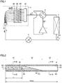
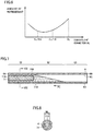
Fig. 1 is a schematic configuration diagram of a refrigeration cycle apparatus in accordance with a first embodiment. -
Fig. 2 is a schematic cross sectional view of a heat transfer tube of a first heat exchanger when the refrigeration cycle apparatus in accordance with the first embodiment is in a first state. -
Fig. 3 is a schematic cross sectional view seen from arrows III-III inFig. 2 . -
Fig. 4 is a schematic cross sectional view seen from arrows IV-IV inFig. 2 . -
Fig. 5 is a graph showing the relation between the period efficiency of the first heat exchanger and the equivalent diameter of a first tube portion of the first heat exchanger in the refrigeration cycle apparatus in accordance with the first embodiment. -
Fig. 6 is a graph showing the relation between the circulation amount of refrigerant and the equivalent diameter of the first tube portion of the first heat exchanger in the refrigeration cycle apparatus in accordance with the first embodiment. -
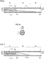
Fig. 7 is a schematic cross sectional view of a heat transfer tube of a first heat exchanger when a refrigeration cycle apparatus in accordance with a third embodiment is in the first state. -
Fig. 8 is a schematic cross sectional view seen from arrows VIII-VIII inFig. 7 . -
Fig. 9 is a schematic cross sectional view of the heat transfer tube of the first heat exchanger when the refrigeration cycle apparatus in accordance with the third embodiment is in a second state. -
Fig. 10 is a schematic cross sectional view seen from arrows X-X inFig. 9 . -
Fig. 11 is a schematic cross sectional view of a heat transfer tube of a first heat exchanger when a refrigeration cycle apparatus in accordance with a fourth embodiment is in the first state. -
Fig. 12 is a schematic cross sectional view seen from arrows XII-XII inFig. 11 . -
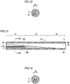
Fig. 13 is a schematic cross sectional view of the heat transfer tube of the first heat exchanger when the refrigeration cycle apparatus in accordance with the fourth embodiment is in the second state. -
Fig. 14 is a schematic cross sectional view seen from arrows XIV-XIV inFig. 13 . -
Fig. 15 is a schematic cross sectional view of a heat transfer tube of a first heat exchanger when a refrigeration cycle apparatus in accordance with a fifth embodiment is in the first state. -
Fig. 16 is a schematic cross sectional view seen from arrows XVI-XVI inFig. 15 . -
Fig. 17 is a flowchart when the refrigeration cycle apparatus in accordance with the fifth embodiment is intermittently operated. -
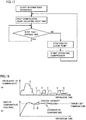
Fig. 18(a) is a graph showing the relation between operation time and compressor frequency when the refrigeration cycle apparatus in accordance with the fifth embodiment is intermittently operated, andFig. 18(b) is a graph showing the relation between operation time and indoor temperature when the refrigeration cycle apparatus in accordance with the fifth embodiment is intermittently operated. -
Fig. 19 is a schematic cross sectional view of a heat transfer tube of a first heat exchanger when a refrigeration cycle apparatus in accordance with a sixth embodiment is in the first state. -
Fig. 20 is a schematic cross sectional view seen from arrows XX-XX inFig. 19 . -
Fig. 21 is a schematic cross sectional view of a heat transfer tube of a first heat exchanger when a refrigeration cycle apparatus in accordance with a seventh embodiment is in the first state. -
Fig. 22 is a schematic cross sectional view seen from arrows XXII-XXII inFig. 21 . -
Fig. 23 is a schematic cross sectional view of a heat transfer tube of the first heat exchanger when a variation of the refrigeration cycle apparatus in accordance with the first embodiment is in the first state. -
Fig. 24 is a schematic cross sectional view seen from arrows XXIV-XXIV inFig. 23 . - Hereinafter, embodiments of the present invention will be described with reference to the drawings. It should be noted that, in the drawings below, identical or corresponding parts will be designated by the same reference numerals, and the description thereof will not be repeated.
- As shown in
Fig. 1 , a refrigeration cycle apparatus 100 in accordance with a first embodiment includes a refrigerant circuit which includes acompressor 1, a four-way valve 2 serving as a flow path switching valve, afirst heat exchanger 3, a second heat exchanger 4, and adecompression unit 5, and through which refrigerant circulates. Refrigeration cycle apparatus 100 is provided to be switchable between a first state in whichfirst heat exchanger 3 acts as a condenser and second heat exchanger 4 acts as an evaporator and a second state in whichfirst heat exchanger 3 acts as an evaporator and second heat exchanger 4 acts as a condenser, by means of four-way valve 2. In the first state, the refrigerant flows throughcompressor 1,first heat exchanger 3,decompression unit 5, and second heat exchanger 4 in order, along a direction F1. In the second state, the refrigerant flows throughcompressor 1, second heat exchanger 4,decompression unit 5, andfirst heat exchanger 3 in order, along a direction F2.First heat exchanger 3 is an indoor heat exchanger placed inside a room, for example. Second heat exchanger 4 is an outdoor heat exchanger placed outside the room, for example. In this case, the first state is achieved during heating operation, and the second state is achieved during cooling operation. - As shown in
Fig. 1 ,first heat exchanger 3 has a plurality of firstheat transfer tubes 6 inside which the refrigerant flows, and is intended to perform heat exchange between the refrigerant flowing inside firstheat transfer tubes 6 and a heat medium such as air, for example, flowing outside firstheat transfer tubes 6.First heat exchanger 3 includes aheat exchange unit 30 including the plurality of firstheat transfer tubes 6 and a fin not shown, adistributor 31, and adistributor 32. Each of the plurality of firstheat transfer tubes 6 offirst heat exchanger 3 has a mutually equal configuration, for example. - As shown in
Figs. 1 and 2 , each of the plurality of firstheat transfer tubes 6 offirst heat exchanger 3 has afirst end portion 6A and asecond end portion 6B provided with refrigerant inlet and outlet.First end portion 6A of each of the plurality of firstheat transfer tubes 6 is connected withdistributor 31.Second end portion 6B of each of the plurality of firstheat transfer tubes 6 is connected withdistributor 32. Further, each of the plurality of firstheat transfer tubes 6 has an innercircumferential surface 6C and an outercircumferential surface 6D. Infirst heat exchanger 3, the refrigerant flows through a region surrounded by innercircumferential surface 6C of each firstheat transfer tube 6. In the first state, the refrigerant condenses from a gas single-phase state through a gas-liquid two-phase state to a liquid single-phase state in the course of flowing fromsecond end portion 6B tofirst end portion 6A of each of the plurality of firstheat transfer tubes 6. In the second state, the refrigerant evaporates from a gas-liquid two-phase state to a gas single-phase state in the course of flowing fromfirst end portion 6A tosecond end portion 6B of each of the plurality of firstheat transfer tubes 6. - As shown in
Fig. 2 , each of the plurality of firstheat transfer tubes 6 offirst heat exchanger 3 can be divided into athird tube portion 63 located upstream of an intermediate position of firstheat transfer tube 6 in flowing direction F1 of the refrigerant in the first state, afourth tube portion 62 including the intermediate position and located downstream ofthird tube portion 63 in direction F1, and afirst tube portion 61 located downstream offourth tube portion 62 in direction F1.First tube portion 61 is located downstream of the intermediate position of firstheat transfer tube 6 in direction F1. Flowing direction F1 of the refrigerant inside firstheat transfer tube 6 extends along an axis line direction of firstheat transfer tube 6. The axis line direction of firstheat transfer tube 6 may extend linearly, or may meander. A material constituting firstheat transfer tube 6 includes copper (Cu), for example. -
First heat exchanger 3 includes a plurality of firstinner members 7, for example. Each firstinner member 7 is arranged inside eachfirst tube portion 61. Each firstinner member 7 has a mutually equal configuration, for example. - As shown in
Fig. 2 , firstinner member 7 has athird end portion 7A and afourth end portion 7B.Third end portion 7A of firstinner member 7 is arranged at a position closer tofirst end portion 6A of firstheat transfer tube 6 thanfourth end portion 7B. An end portion offirst tube portion 61 located closer tofourth tube portion 62 is a portion arranged on a cross section perpendicular to the axis line direction of firstheat transfer tube 6, on whichfourth end portion 7B of firstinner member 7 is also arranged. - As shown in
Fig. 2 , firstinner member 7 has an outercircumferential surface 7D. At least a portion of outercircumferential surface 7D is arranged to face innercircumferential surface 6C offirst tube portion 61 with a space therebetween. The refrigerant flowing throughfirst tube portion 61 flows through a region sandwiched between innercircumferential surface 6C offirst tube portion 61 and outercircumferential surface 7D of firstinner member 7. Insidefirst tube portion 61, only one refrigerant flow path is arranged, for example. On a cross section perpendicular to the axis line direction, a shape formed by outercircumferential surface 7D of firstinner member 7 is similar to a shape formed by innercircumferential surface 6C of firstheat transfer tube 6, for example. The shape formed by outercircumferential surface 7D of firstinner member 7 and the shape formed by innercircumferential surface 6C of firstheat transfer tube 6 are circular, for example. - On the cross section perpendicular to the axis line direction, the following relational expression (5) is satisfied, where E1 is a length of the outer circumferential surface of first
inner member 7, E2 is a length of the inner circumferential surface of firstheat transfer tube 6, and S is a wetted perimeter offirst tube portion 61. On the cross section perpendicular to the axis line direction, the above relational expression (1) is satisfied, where D1 is an inner diameter offirst tube portion 61, A1 is a flow path cross sectional area offirst tube portion 61, and M1 is an equivalent diameter offirst tube portion 61.
- As shown in
Fig. 3 , equivalent diameter M1 offirst tube portion 61 satisfies the following relational expression (6) in the first state and the second state. Preferably, equivalent diameter M1 offirst tube portion 61 satisfies the above relational expression (2) in the first state and the second state.
- As shown in
Fig. 2 ,first tube portion 61 includes a portion through which the liquid phase refrigerant flows when refrigeration cycle apparatus 100 is in the first state.First tube portion 61 includes a portion through which for example the gas-liquid two-phase refrigerant flows when refrigeration cycle apparatus 100 is in the second state.Fourth tube portion 62 includes a portion through which the gas-liquid two-phase refrigerant flows when refrigeration cycle apparatus 100 is in the first state.Third tube portion 63 includes a portion through which the gas phase refrigerant flows when refrigeration cycle apparatus 100 is in the first state. It should be noted thatFig. 2 schematically shows the refrigerant in order to describe the change of state thereof.
For example,Fig. 2 merely shows that the refrigerant insidefourth tube portion 62 is in the gas-liquid two-phase state, andFig. 2 does not show a mixed state and a flowing state of a liquid phase portion and a gas phase portion of the refrigerant in the gas-liquid two-phase state. - A length L1 of first
inner member 7 in the axis line direction of the first tube portion is less than or equal to half of a length L2 of firstheat transfer tube 6. Length L2 of firstheat transfer tube 6 is a length betweenfirst end portion 6A andsecond end portion 6B of firstheat transfer tube 6 along the axis line direction. - Positional deviation of first
inner member 7 with respect tofirst tube portion 61 of firstheat transfer tube 6 in the axis line direction is restricted by an arbitrary configuration. For example, when the axis line direction of firstheat transfer tube 6 meanders and firstheat transfer tube 6 has a bent portion not shown,first tube portion 61 is located downstream of the bent portion in flowing direction F1. For example, a boundary portion betweenfirst tube portion 61 andfourth tube portion 62 of firstheat transfer tube 6 is provided to be continuous to the bent portion. With such a configuration, firstinner member 7 is positioned between the bent portion andfirst end portion 6A in the axis line direction. - A material constituting first
inner member 7 may be any material. For example, it is a material having a corrosion resistance with respect to the refrigerant which is equal to that of the material constituting firstheat transfer tube 6, and includes at least one selected from the group consisting of copper (Cu), rubber, and plastic, for example. - Refrigeration cycle apparatus 100 includes the refrigerant circuit which includes
compressor 1, four-way valve 2,first heat exchanger 3, second heat exchanger 4, anddecompression unit 5, and through which the refrigerant circulates. The refrigerant circuit is provided to be switchable between the first state in whichfirst heat exchanger 3 acts as a condenser and second heat exchanger 4 acts as an evaporator and the second state in which second heat exchanger 4 acts as a condenser andfirst heat exchanger 3 acts as an evaporator.First heat exchanger 3 includes firstheat transfer tube 6 inside which the refrigerant flows. Firstheat transfer tube 6 hasfirst tube portion 61 located downstream of the intermediate position of firstheat transfer tube 6 in the flowing direction of the refrigerant whenfirst heat exchanger 3 acts as a condenser.First heat exchanger 3 further includes firstinner member 7 arranged insidefirst tube portion 61. In the first state and the second state, inner diameter D1 offirst tube portion 61 and equivalent diameter M1 calculated from the following relational expression (1) satisfy the following relational expression (2):

first tube portion 61, and S1 is the wetted perimeter offirst tube portion 61. - As described above, when refrigeration cycle apparatus 100 is in the first state, the refrigerant condenses in the course of flowing through
third tube portion 63,fourth tube portion 62, andfirst tube portion 61 of firstheat transfer tube 6 offirst heat exchanger 3 in order, and changes from the gas single-phase state through the gas-liquid two-phase state to the liquid single-phase state. On the other hand, when refrigeration cycle apparatus 100 is in the second state, the refrigerant evaporates in the course of flowing throughfirst tube portion 61,fourth tube portion 62, andthird tube portion 63 of firstheat transfer tube 6 offirst heat exchanger 3 in order, and changes from the gas-liquid two-phase state to the gas single-phase state. That is, the refrigerant flowing throughfirst tube portion 61 is mainly in the liquid single-phase state in the first state, and is mainly in the gas-liquid two-phase state in the second state. In addition, in the first state and the second state, the refrigerant in the liquid single-phase state flows through onlyfirst tube portion 61 and rarely flows throughfourth tube portion 62 andthird tube portion 63 of firstheat transfer tube 6. - Since first
inner member 7 is arranged insidefirst tube portion 61 of firstheat transfer tube 6, flow path cross sectional area A offirst tube portion 61 is smaller than flow path cross sectional areas offourth tube portion 62 andthird tube portion 63 of firstheat transfer tube 6 inside which firstinner member 7 is not arranged. Accordingly, the flow velocity of the refrigerant in the liquid single-phase state when it flows throughfirst tube portion 61 is faster than the flow velocity of the refrigerant in the liquid single-phase state when it flows through a conventional heat transfer tube in which firstinner member 7 is not arranged. As a result, the in-tube heat transfer performance offirst tube portion 61 in the first state is higher than the in-tube heat transfer performance of the conventional heat transfer tube in which firstinner member 7 is not arranged. - In addition, the heat exchanger provided with the insertion body described in
PTL 1 does not satisfy the above relational expression (2). Specifically, as shown inFig. 9 ofPTL 1, an equivalent diameter Mr and an inner diameter Dr of the portion in which the insertion body is inserted satisfy a relational expression Mr < Dr/2.5. - In contrast, since equivalent diameter M of
first tube portion 61 satisfies the above relational expression (2), the period efficiency offirst heat exchanger 3 in refrigeration cycle apparatus 100 is improved, when compared with the heat exchanger in PTL1 which does not satisfy the above relational expression (2).Fig. 5 is a graph showing the relation between equivalent diameter M offirst tube portion 61 and the heat exchange performance offirst heat exchanger 3 in the first state (a line segment A inFig. 5 ), the heat exchange performance offirst heat exchanger 3 in the second state (a line segment B inFig. 5 ), and the period efficiency of first heat exchanger 3 (a line segment C inFig. 5 ). The axis of abscissas inFig. 5 represents equivalent diameter M offirst tube portion 61, and the axis of ordinates inFig. 5 represents the heat exchange performance and the period efficiency offirst heat exchanger 3. - As shown in
Fig. 5 , in a case where equivalent diameter M1 offirst tube portion 61 is less than or equal to D1/2.5, the period efficiency offirst heat exchanger 3 is significantly decreased, when compared with a case where equivalent diameter M1 offirst tube portion 61 is more than Di/2.5. - Referring to line segment B in
Fig. 5 , in the case where equivalent diameter M1 offirst tube portion 61 is less than or equal to D1/2.5, the pressure loss of the refrigerant in the gas-liquid two-phase state flowing throughfirst tube portion 61 in the second state is significantly increased, and the heat exchange performance offirst heat exchanger 3 in the second state is significantly decreased, when compared with the case where equivalent diameter M1 offirst tube portion 61 is more than D1/2.5. On the other hand, referring to line segment A inFig. 5 , in the case where equivalent diameter M1 offirst tube portion 61 is less than or equal to Di/2.5, the velocity of the refrigerant in the liquid single-phase state flowing throughfirst tube portion 61 in the first state is not significantly increased, and thus the heat exchange performance offirst heat exchanger 3 in the first state is not significantly improved, when compared with the case where equivalent diameter M1 offirst tube portion 61 is more than D1/2.5. Due to the above reason, the period efficiency offirst heat exchanger 3 in which equivalent diameter M1 offirst tube portion 61 is more than D1/2.5 is significantly improved, when compared with the period efficiency of the heat exchanger inPTL 1 in which equivalent diameter Mr in the heat transfer tube having inner diameter Dr is less than Dr/2.5. - In addition, as shown in
Fig. 5 , in a case where equivalent diameter M1 offirst tube portion 61 is more than or equal to Di/1.5, the period efficiency offirst heat exchanger 3 is not fully improved, when compared with a case where equivalent diameter M1 offirst tube portion 61 is less than Di/1.5. In the case where equivalent diameter M1 offirst tube portion 61 is more than or equal to D1/1.5, the pressure loss of the refrigerant in the gas-liquid two-phase state flowing throughfirst tube portion 61 in the second state is suppressed, when compared with the case where equivalent diameter M1 offirst tube portion 61 is less than D1/1.5. However, in the case where equivalent diameter M1 offirst tube portion 61 is more than or equal to D1/1.5, the velocity of the refrigerant in the liquid single-phase state flowing throughfirst tube portion 61 in the first state is not fully increased, and thus the heat exchange performance offirst heat exchanger 3 in the first state is not fully significantly improved, when compared with the case where equivalent diameter M1 offirst tube portion 61 is less than Di/1.5.
Due to the above reason, the period efficiency offirst heat exchanger 3 in which equivalent diameter M1 offirst tube portion 61 is less than D1/1.5 is significantly improved, when compared with the case where equivalent diameter M1 offirst tube portion 61 is more than or equal to D1/1.5. - In addition, as shown in
Fig. 6 , since equivalent diameter M1 offirst tube portion 61 is more than D1/2.5 in refrigeration cycle apparatus 100, the amount of refrigerant enclosed in the refrigerant circuit can be reduced, when compared with the case where equivalent diameter M1 offirst tube portion 61 is less than or equal to D1/2.5. A surface area of the outer circumferential surface of firstinner member 7 in the case where equivalent diameter M1 offirst tube portion 61 is more than Di/2.5 is smaller than a surface area of the outer circumferential surface of firstinner member 7 in the case where equivalent diameter M1 offirst tube portion 61 is less than or equal to D1/2.5. Accordingly, the amount of refrigerant remaining insidefirst tube portion 61 in which equivalent diameter M1 is more than Di/2.5 is smaller than the amount of refrigerant remaining insidefirst tube portion 61 in which equivalent diameter M1 is less than or equal to D1/2.5. As a result, the amount of refrigerant enclosed in the refrigerant circuit of refrigeration cycle apparatus 100 can be reduced, when compared with that inPTL 1 in which equivalent diameter Mr in the heat transfer tube having inner diameter Dr is less than Dr/2.5. It should be noted that, when refrigerant and oil circulate through the refrigerant circuit of refrigeration cycle apparatus 100, the amount of oil enclosed in the refrigerant circuit can also be reduced, when compared with that inPTL 1, due to the same reason as that for the refrigerant. - In addition, in refrigeration cycle apparatus 100, only one refrigerant flow path is arranged inside
first tube portion 61. When a plurality of refrigerant flow paths are arranged insidefirst tube portion 61, the refrigerant is distributed to the plurality of refrigerant flow paths. In this case, depending on the distribution ratio between the plurality of refrigerant flow paths, the in-tube heat transfer performance of firstheat transfer tube 6 in the second state is deteriorated. Accordingly, the distribution ratio between the plurality of refrigerant flow paths should be set so as not to deteriorate the in-tube heat transfer performance of firstheat transfer tube 6 in the second state in which the refrigerant in the gas-liquid two-phase state flows throughfirst tube portion 61. In contrast, in refrigeration cycle apparatus 100, deterioration of in-tube heat transfer performance due to the distribution ratio described above is not caused. - It should be noted that, in the heat exchanger in
PTL 1, a plurality of refrigerant flow paths divided by a plurality of projections are arranged, and when the heat exchanger acts as an evaporator, the refrigerant in the gas-liquid two-phase state flows around the insertion body. However, in the heat exchanger inPTL 1, the distribution ratio of the refrigerant in the gas-liquid two-phase state is not taken into consideration. Accordingly, heat exchange performance in a case wherefirst heat exchanger 3 acts as an evaporator is improved, when compared with that of the heat exchanger inPTL 1. - A refrigeration cycle apparatus in accordance with a second embodiment has basically the same configuration as that of refrigeration cycle apparatus 100 in accordance with the first embodiment, and differs therefrom in that length L1 of first inner member 7 (see
Fig. 6 ) in the axis line direction offirst tube portion 61 is defined to be less than 1/3 of length L2 of first heat transfer tube 6 (seeFig. 6 ). - When length L1 of first
inner member 7 is more than or equal to 1/3 of length L2 of firstheat transfer tube 6, a portion in which the refrigerant in the liquid single-phase state flows in firstheat transfer tube 6 can be restricted withinfirst tube portion 61. On the other hand, in this case, the refrigerant in the gas-liquid two-phase state flows upstream offirst tube portion 61 in the first state, which may increase pressure loss. - Since length L1 of first
inner member 7 is less than 1/3 of length L2 of firstheat transfer tube 6 in the refrigeration cycle apparatus in accordance with the second embodiment, such a configuration suppresses an increase in pressure loss associated with the refrigerant in the gas-liquid two-phase state flowing throughfirst tube portion 61 in the first state. - In addition, since the refrigeration cycle apparatus in accordance with the second embodiment has the same configuration as that of refrigeration cycle apparatus 100 in accordance with the first embodiment except for the above configuration, it can exhibit the same effect as that of refrigeration cycle apparatus 100.
- As shown in
Figs. 7 to 10 , a refrigeration cycle apparatus in accordance with a third embodiment has basically the same configuration as that of refrigeration cycle apparatus 100 in accordance with the first embodiment, and differs therefrom in that it includes a firstinner member 71 instead of firstinner member 7. Firstinner member 71 differs from firstinner member 7 in that a thermal expansion coefficient of a material constituting firstinner member 71 is higher than a thermal expansion coefficient of the material constituting firstheat transfer tube 6. - In the first state, first
inner member 71 thermally expands, when compared with firstheat transfer tube 6. Further, a temperature of the liquid single-phase refrigerant flowing throughfirst tube portion 61 in the first state (hereinafter referred to as a first temperature) is higher than a temperature of the gas-liquid two-phase refrigerant flowing throughfirst tube portion 61 in the second state (hereinafter referred to as a second temperature). Accordingly, firstinner member 71 in the first state thermally expands, when compared with firstinner member 71 in the second state. As a result, in the refrigeration cycle apparatus in accordance with the third embodiment, flow path cross sectional area A offirst tube portion 61 of firstheat transfer tube 6 in the first state is smaller than flow path cross sectional area A offirst tube portion 61 of firstheat transfer tube 6 in the second state. - That is, both an equivalent diameter M3 of
first tube portion 61 of firstheat transfer tube 6 in the first state and an equivalent diameter M4 offirst tube portion 61 of firstheat transfer tube 6 in the second state satisfy the above relational expression (2) as with equivalent diameter M1, and equivalent diameter M3 is smaller than equivalent diameter M4. That is, the refrigeration cycle apparatus in accordance with the third embodiment satisfies the following relational expression (7):
- As described above, in the refrigeration cycle apparatus in accordance with the third embodiment, equivalent diameter M3 of
first tube portion 61 of firstheat transfer tube 6 whenfirst heat exchanger 3 acts as a condenser is smaller than equivalent diameter M4 offirst tube portion 61 of firstheat transfer tube 6 whenfirst heat exchanger 3 acts as an evaporator. Accordingly, the period efficiency of the refrigeration cycle apparatus in accordance with the third embodiment is improved, when compared with the period efficiency of refrigeration cycle apparatus 100 in accordance with the first embodiment. - For example, when first
inner member 71 is designed such that equivalent diameter M1 in the first state is equal to that of refrigeration cycle apparatus 100, equivalent diameter M2 in the second state is smaller than that of refrigeration cycle apparatus 100. Infirst heat exchanger 3 including such firstinner member 71, the pressure loss infirst tube portion 61 in the second state is decreased, and thus heat exchange performance is improved, when compared withfirst heat exchanger 3 including firstinner member 7. - In addition, when first
inner member 71 is designed such that equivalent diameter M4 in the second state is equal to that of refrigeration cycle apparatus 100, equivalent diameter M1 in the first state is larger than that of refrigeration cycle apparatus 100. Infirst heat exchanger 3 including such firstinner member 71, the velocity of the refrigerant in the liquid single-phase state in the first state is increased, and thus heat exchange performance is improved, when compared withfirst heat exchanger 3 including firstinner member 7. - In addition, since the refrigeration cycle apparatus in accordance with the third embodiment has the same configuration as that of refrigeration cycle apparatus 100 in accordance with the first embodiment except for the above configuration, it can exhibit the same effect as that of refrigeration cycle apparatus 100. It should be noted that the refrigeration cycle apparatus in accordance with the third embodiment may have the same configuration as that of the refrigeration cycle apparatus in accordance with the second embodiment except for the above configuration.
- As shown in
Figs. 11 to 14 , a refrigeration cycle apparatus in accordance with a fourth embodiment has basically the same configuration as that of refrigeration cycle apparatus 100 in accordance with the first embodiment, and differs therefrom in that it includes a firstinner member 72 instead of firstinner member 7. Firstinner member 72 differs from firstinner member 7 in that a material constituting firstinner member 72 includes a shape memory alloy. - First
inner member 72 is provided to be deformed between the first state and the second state. Firstinner member 72 is deformed such that flow path cross sectional area A offirst tube portion 61 of firstheat transfer tube 6 in the first state is smaller than flow path cross sectional area A offirst tube portion 61 of firstheat transfer tube 6 in the second state. That is, both equivalent diameter M3 offirst tube portion 61 of firstheat transfer tube 6 in the first state and equivalent diameter M4 offirst tube portion 61 of firstheat transfer tube 6 in the second state satisfy the above relational expression (2) as with equivalent diameter M1, and equivalent diameter M3 is smaller than equivalent diameter M4. - The temperature of the liquid single-phase refrigerant flowing through
first tube portion 61 in the first state (hereinafter referred to as the first temperature) is higher than the temperature of the gas-liquid two-phase refrigerant flowing throughfirst tube portion 61 in the second state (hereinafter referred to as the second temperature). - The transition temperature of the shape memory alloy constituting first
inner member 72 is less than or equal to the first temperature and more than the second temperature. When the temperature of firstinner member 72 is less than the transition temperature, firstinner member 72 is deformed under the pressure of the refrigerant in the gas-liquid two-phase state in the second state, for example. When the temperature of firstinner member 72 is more than or equal to the transition temperature, firstinner member 72 is restored from the deformed state. - Such a refrigeration cycle apparatus in accordance with the fourth embodiment satisfies the following relational expression (7), as with the refrigeration cycle apparatus in accordance with the third embodiment:

- As described above, in the refrigeration cycle apparatus in accordance with the fourth embodiment, equivalent diameter M1 of
first tube portion 61 of firstheat transfer tube 6 whenfirst heat exchanger 3 acts as a condenser is smaller than equivalent diameter M2 offirst tube portion 61 of firstheat transfer tube 6 whenfirst heat exchanger 3 acts as an evaporator. Accordingly, the period efficiency of the refrigeration cycle apparatus in accordance with the fourth embodiment is improved, when compared with the period efficiency of refrigeration cycle apparatus 100 in accordance with the first embodiment. - For example, when first
inner member 72 is designed such that equivalent diameter M1 in the first state is equal to that of refrigeration cycle apparatus 100, equivalent diameter M2 in the second state is smaller than that of refrigeration cycle apparatus 100. Infirst heat exchanger 3 including such firstinner member 72, the pressure loss infirst tube portion 61 in the second state is decreased, and thus heat exchange performance is improved, when compared withfirst heat exchanger 3 including firstinner member 7. - In addition, when first
inner member 72 is designed such that equivalent diameter M2 in the second state is equal to that of refrigeration cycle apparatus 100, equivalent diameter M1 in the first state is larger than that of refrigeration cycle apparatus 100. Infirst heat exchanger 3 including such firstinner member 72, the velocity of the refrigerant in the liquid single-phase state in the first state is increased, and thus heat exchange performance is improved, when compared withfirst heat exchanger 3 including firstinner member 7. - In addition, since the refrigeration cycle apparatus in accordance with the fourth embodiment has the same configuration as that of refrigeration cycle apparatus 100 in accordance with the first embodiment except for the above configuration, it can exhibit the same effect as that of refrigeration cycle apparatus 100. It should be noted that the refrigeration cycle apparatus in accordance with the fourth embodiment may have the same configuration as that of the refrigeration cycle apparatus in accordance with the second embodiment except for the above configuration.
- As shown in
Figs. 15 and 16 , a refrigeration cycle apparatus in accordance with a fifth embodiment has basically the same configuration as that of refrigeration cycle apparatus 100 in accordance with the first embodiment, and differs therefrom in that it includes a firstinner member 73 instead of firstinner member 7. Firstinner member 73 differs from firstinner member 7 in that a specific heat of a material constituting firstinner member 73 is higher than a specific heat of the material constituting firstheat transfer tube 6. - The material constituting first
inner member 73 includes aluminum (Al), for example. A heat capacity of firstinner member 73 is larger than a heat capacity offirst tube portion 61, for example. Firstinner member 73 may be constituted of a single material, or may be constituted of a plurality of materials. The material constituting firstinner member 73 may include a material having a specific heat equal to that of the material constituting firstheat transfer tube 6, and a material having a specific heat higher than that of that material. The material constituting firstinner member 73 may include copper (Cu), and any material having a specific heat higher than that of Cu, for example. In addition, firstinner member 73 may be constituted by an external member provided with an internal space partitioned from the outside, and a filling member which fills the internal space. In this case, a material constituting the external member includes Cu, and a material constituting the filling member may include any material having a specific heat higher than that of Cu, for example, at least one of oil and water. - As shown in
Figs. 17, 18(a) and 18(b) , the refrigeration cycle apparatus in accordance with the fifth embodiment is provided such that it can perform intermittent operation in the first state. The intermittent operation is operation that alternately switches between a state wherecompressor 1 is driven and a state wherecompressor 1 is stopped. In the following, an example of a control flow for the intermittent operation in the first state is described, taking a case where the refrigeration cycle apparatus performs heating operation as the first state, as an example. - When the intermittent operation is started in the refrigeration cycle apparatus in accordance with the fifth embodiment,
compressor 1 is driven and the first state is maintained until the indoor temperature becomes equal to or higher than a target set temperature, for example. Thereafter, when it is confirmed that the indoor temperature becomes equal to or higher than the target set temperature,compressor 1 is stopped, and circulation of the refrigerant through the refrigerant circuit is also stopped. On this occasion, when a heat medium that exchanges heat with the refrigerant infirst heat exchanger 3 is air or the like, a fan for supplying the air tofirst heat exchanger 3 is driven continuously. In addition, when the heat medium is a brine or the like, a pump for supplying the brine tofirst heat exchanger 3 is driven continuously. Stop time ofcompressor 1 is counted. The fan or the pump is driven until the stop time ofcompressor 1 becomes equal to or longer than a set time. Thereafter, when it is confirmed that the stop time ofcompressor 1 becomes equal to or longer than the set time, the fan or the pump is stopped. Thereafter, when it is confirmed that the indoor temperature becomes lower than the target set temperature, driving ofcompressor 1 and the fan or the pump is resumed. - When such intermittent operation is performed, the frequency of
compressor 1 is controlled as shown inFig. 18(a) . In addition, as a result of such intermittent operation, the indoor temperature changes as shown inFig. 18(b) . InFigs. 18(a) and 18(b) , a line segment D indicates the state of the intermittent operation in the refrigeration cycle apparatus in accordance with the fifth embodiment, and a line segment E indicates the state of the intermittent operation in a conventional refrigeration cycle apparatus in which driving of a compressor and a fan or a pump is stopped simultaneously when it is confirmed that the indoor temperature becomes equal to or higher than the target set temperature. - As shown in
Figs. 18(a) and 18(b) , in the refrigeration cycle apparatus in accordance with the fifth embodiment, although the number of times of operation ofcompressor 1 is reduced, a decrease in the indoor temperature is suppressed, when compared with the conventional refrigeration cycle apparatus. In the conventional refrigeration cycle apparatus, the amount of heat of a heat transfer tube of an indoor heat exchanger and the amount of heat of refrigerant remaining inside the heat transfer tube as the driving of the compressor is stopped are lost relatively quickly, due to heat exchange with a heat medium existing outside the heat transfer tube. As a result, the indoor temperature after the driving of the compressor is stopped decreases relatively quickly to lower than the target set temperature. - In contrast, in the refrigeration cycle apparatus in accordance with the fifth embodiment, while
compressor 1 is driven, a portion of the amount of heat of the refrigerant flowing throughfirst tube portion 61 is accumulated in firstinner member 73. Accordingly, even when the driving ofcompressor 1 is stopped, firstheat transfer tube 6 and the refrigerant remaining inside firstheat transfer tube 6 can receive supply of the amount of heat from firstinner member 73. Thereby, in the refrigeration cycle apparatus in accordance with the fifth embodiment, a decrease in the indoor temperature during the intermittent operation proceeds slowly, and thus comfortableness during the intermittent operation is improved, when compared with the conventional refrigeration cycle apparatus. - Further, in the refrigeration cycle apparatus in accordance with the fifth embodiment, the stop time of
compressor 1 can be increased, and thus the number of times of driving ofcompressor 1 within a predetermined time can be reduced, when compared with the conventional refrigeration cycle apparatus. As a result, the refrigeration cycle apparatus in accordance with the fifth embodiment can reduce power consumption, and further can reduce load oncompressor 1, and thus has a high reliability, when compared with the conventional refrigeration cycle apparatus. - In addition, since the refrigeration cycle apparatus in accordance with the fifth embodiment has the same configuration as that of refrigeration cycle apparatus 100 in accordance with the first embodiment except for the above configuration, it can exhibit the same effect as that of refrigeration cycle apparatus 100. It should be noted that the refrigeration cycle apparatus in accordance with the fifth embodiment may have the same configuration as that of any of the refrigeration cycle apparatuses in accordance with the second to fourth embodiments except for the above configuration.
- As shown in
Figs. 19 and 20 , a refrigeration cycle apparatus in accordance with a sixth embodiment has basically the same configuration as that of refrigeration cycle apparatus 100 in accordance with the first embodiment, and differs therefrom in thatfirst tube portion 61 has a plurality ofprotrusions 64 protruding with respect to innercircumferential surface 6C that faces outercircumferential surface 7D of firstinner member 7. - The plurality of
protrusions 64 extend along the axis line direction. Each of the plurality ofprotrusions 64 has afifth end portion 64A located closer tofirst end portion 6A, and asixth end portion 64B located closer tosecond end portion 6B, in the axis line direction.Sixth end portion 64B andfourth end portion 7B of firstinner member 7 are arranged on the same cross section perpendicular to the axis line direction. - The plurality of
protrusions 64 are arranged to be spaced from each other in a circumferential direction with respect to the axis line direction. The number ofprotrusions 64 arranged to be spaced from each other in the circumferential direction may be any number that is two or more, and is five, for example. Each of the plurality ofprotrusions 64 has a mutually equal configuration, for example. The plurality ofprotrusions 64 are fixed tofirst tube portion 61. A material constituting the plurality ofprotrusions 64 may be any material. For example, it is a material having a corrosion resistance with respect to the refrigerant which is equal to that of the material constituting firstheat transfer tube 6, and includes at least one selected from the group consisting of copper (Cu), rubber, and plastic, for example. - The plurality of
protrusions 64 are in contact with outercircumferential surface 7D of firstinner member 7. The plurality ofprotrusions 64 are provided to maintain a state where outercircumferential surface 7D and innercircumferential surface 6C offirst tube portion 61 are arranged with a space therebetween. The plurality ofprotrusions 64 are provided such thatfirst tube portion 61 and firstinner member 7 are coaxially arranged. In other words, the plurality ofprotrusions 64 are provided such that an axis line offirst tube portion 61 matches an axis line of firstinner member 7. Positional deviation of firstinner member 7 with respect tofirst tube portion 61 in a direction perpendicular to the axis line direction is suppressed by the plurality ofprotrusions 64. Positional deviation of firstinner member 7 with respect tofirst tube portion 61 in the axis line direction, for example, is also suppressed by the plurality ofprotrusions 64. - In order to suppress a decrease in the heat exchange performance of
first heat exchanger 3 associated with the refrigerant in the gas-liquid two-phase state flowing throughfirst tube portion 61 in the second state being distributed by the plurality ofprotrusions 64, the distribution ratio of the refrigerant in the gas-liquid two-phase state distributed by the plurality ofprotrusions 64 is designed as appropriate. - A cross sectional area perpendicular to the axis line direction of the plurality of
protrusions 64, that is, a total value of cross sectional areas perpendicular to the axis line direction ofrespective protrusions 64, is less than a cross sectional area perpendicular to the axis line direction of firstinner member 7. - Such a refrigeration cycle apparatus in accordance with the sixth embodiment satisfies the above relational expression (2), as with the refrigeration cycle apparatus in accordance with the first embodiment. It should be noted that, when comparison is made between
first tube portion 61 in accordance with the sixth embodiment andfirst tube portion 61 in accordance with the first embodiment having equal inner diameter D1 and including firstinner member 7 having an equal configuration, flow path cross sectional area A offirst tube portion 61 in accordance with the sixth embodiment is smaller than flow path cross sectional area A offirst tube portion 61 in accordance with the first embodiment, and thus equivalent diameter M1 offirst tube portion 61 in accordance with the sixth embodiment is smaller than equivalent diameter M1 offirst tube portion 61 in accordance with the first embodiment. - In the refrigeration cycle apparatus in accordance with the sixth embodiment, since the plurality of
protrusions 64 maintain the state where outercircumferential surface 7D and innercircumferential surface 6C offirst tube portion 61 are arranged with a space therebetween, vibration of firstinner member 7 due to pulsation of the refrigerant is suppressed. As a result, in the refrigeration cycle apparatus in accordance with the sixth embodiment, occurrence of noise associated with the vibration of firstinner member 7 is suppressed, and comfortableness is improved, when compared with refrigeration cycle apparatus 100 in accordance with the first embodiment. - In addition, since the plurality of
protrusions 64 prevent contact between outercircumferential surface 7D of firstinner member 7 and innercircumferential surface 6C offirst tube portion 61, a decrease in heat transfer area in innercircumferential surface 6C offirst tube portion 61 is suppressed. - In addition, since the refrigeration cycle apparatus in accordance with the sixth embodiment has the same configuration as that of refrigeration cycle apparatus 100 in accordance with the first embodiment except for the above configuration, it can exhibit the same effect as that of refrigeration cycle apparatus 100. It should be noted that the refrigeration cycle apparatus in accordance with the sixth embodiment may have the same configuration as that of any of the refrigeration cycle apparatuses in accordance with the second to fifth embodiments except for the above configuration.
- As shown in
Figs. 19 and 20 , innercircumferential surface 6C offirst tube portion 61 may be provided with a plurality of groove portions. The plurality of groove portions are arranged to be spaced from each other in the circumferential direction. Between two groove portions adjacent in the circumferential direction, each of a plurality ofminute protrusions 65 or the plurality ofprotrusions 64 provided to protrude with respect to bottom portions of the groove portions is arranged. That is, eachprotrusion 64 is arranged between two groove portions adjacent in the circumferential direction. In a cross section perpendicular to the axis line direction, a tip of eachminute protrusion 65 has an intersection at which two curved surfaces intersect to form an acute angle therebetween, for example. The height of eachprotrusion 64 with respect to innercircumferential surface 6C is higher than the height of eachminute protrusion 65 with respect to innercircumferential surface 6C. The number ofminute protrusions 65 arranged to be spaced from each other in the circumferential direction may be any number that is two or more, and is more than the number of the plurality ofprotrusions 64, for example. Each of the plurality ofminute protrusions 65 has a mutually equal configuration, for example. - In a case where
first tube portion 61 is provided with the plurality ofminute protrusions 65 as described above, the heat transfer area in innercircumferential surface 6C offirst tube portion 61 is increased, and thus the heat exchange performance offirst heat exchanger 3 is improved, when compared with a case wherefirst tube portion 61 is not provided with the plurality ofminute protrusions 65. - As shown in
Figs. 21 and 22 , a refrigeration cycle apparatus in accordance with a seventh embodiment has basically the same configuration as that of the refrigeration cycle apparatus in accordance with the sixth embodiment, and differs therefrom in that the plurality ofprotrusions 64 are arranged to be spaced from each other in the axis line direction. That is, the plurality ofprotrusions 64 are arranged to be spaced from each other in the circumferential direction with respect to the axis line direction, and are also arranged to be spaced from each other in the axis line direction. - The number of
protrusions 64 arranged to be spaced from each other in the axis line direction may be any number that is two or more, and is three, for example. Each of the plurality ofprotrusions 64 has a mutually equal configuration, for example. - Such a refrigeration cycle apparatus in accordance with the seventh embodiment satisfies the above relational expression (2), as with the refrigeration cycle apparatus in accordance with the first embodiment.
- In the refrigeration cycle apparatus in accordance with the seventh embodiment, since the plurality of
protrusions 64 are arranged to be spaced from each other in the axis line direction, occurrence of pressure loss resulting from the plurality ofprotrusions 64 is suppressed, when compared with the refrigeration cycle apparatus in accordance with the sixth embodiment. As a result, in the refrigeration cycle apparatus in accordance with the seventh embodiment, the heat exchange performance offirst heat exchanger 3 in the second state is improved, and period efficiency is improved, when compared with the refrigeration cycle apparatus in accordance with the sixth embodiment. - In addition, since the refrigeration cycle apparatus in accordance with the seventh embodiment has the same configuration as that of refrigeration cycle apparatus 100 in accordance with the first embodiment except for the above configuration, it can exhibit the same effect as that of refrigeration cycle apparatus 100. It should be noted that the refrigeration cycle apparatus in accordance with the seventh embodiment may have the same configuration as that of any of the refrigeration cycle apparatuses in accordance with the second to fifth embodiments except for the above configuration.
- Although
first heat exchanger 3 includes firstinner member inner members Fig. 23 shows a configuration in which second heat exchanger 4 includes a secondinner member 9 having the same configuration as that of firstinner member 7. - As shown in
Figs. 23 and 24 , second heat exchanger 4 has a plurality of secondheat transfer tubes 8 having the same configuration as that of firstheat transfer tubes 6 offirst heat exchanger 3. Each of secondheat transfer tubes 8 can be divided into afifth tube portion 83 located upstream of an intermediate position of secondheat transfer tube 8 in flowing direction F2 of the refrigerant in the second state, asixth tube portion 82 including the intermediate position of secondheat transfer tube 8 and located downstream offifth tube portion 83 in direction F2, and asecond tube portion 81 located downstream ofsixth tube portion 82 in direction F2.Second tube portion 81 of the second heat transfer tube is a portion located downstream of the intermediate position of secondheat transfer tube 8 in flowing direction F2 of the refrigerant when second heat exchanger 4 acts as a condenser.Second tube portion 81 of the second heat transfer tube corresponds tofirst tube portion 61 of firstheat transfer tube 6,sixth tube portion 82 of secondheat transfer tube 8 corresponds tofourth tube portion 62 of firstheat transfer tube 6, andfifth tube portion 83 of secondheat transfer tube 8 corresponds tothird tube portion 63 of firstheat transfer tube 6.Second tube portion 81 of secondheat transfer tube 8 includes a portion through which the liquid phase refrigerant flows when the refrigeration cycle apparatus is in the second state.Second tube portion 81 of secondheat transfer tube 8 includes a portion through which for example the gas-liquid two-phase refrigerant flows when the refrigeration cycle apparatus is in the first state. - When second heat exchanger 4 includes a plurality of second
inner members 9, each secondinner member 9 is arranged insidesecond tube portion 81 of each secondheat transfer tube 8. In this case, an equivalent diameter M2 ofsecond tube portion 81 of secondheat transfer tube 8 is calculated from the following relational expression (3), as with equivalent diameter M1 offirst tube portion 61 of first heat transfer tube 6:
second tube portion 81, and S2 is a wetted perimeter ofsecond tube portion 81. - Further, equivalent diameter M2 and an inner diameter D2 of
second tube portion 81 satisfy the following relational expression (4) in the first state and the second state:
- In addition, the heat exchange performance of such second heat exchanger 4 in the second state is indicated by line segment A in
Fig. 5 , the heat exchange performance of second heat exchanger 4 in the first state is indicated by line segment B inFig. 5 , and the period efficiency of second heat exchanger 4 is indicated by line segment C inFig. 5 . - Accordingly, the in-tube heat transfer performance of
second tube portion 81 of secondheat transfer tube 8 in the second state is higher than that in a case where secondinner member 9 is not arranged. In addition, the period efficiency of second heat exchanger 4 as described above is higher than the period efficiency of a heat exchanger provided with an insertion body which does not satisfy the above relational expression (4). In addition, the second inner member may have the same configuration as that of firstinner member - In addition, first
inner member first tube portion 61 of the plurality of firstheat transfer tubes 6 offirst heat exchanger 3. Secondinner member 9 may be arranged inside at least onesecond tube portion 81 of the plurality of secondheat transfer tubes 8 of second heat exchanger 4. - Although the embodiments of the present invention have been described above, it is also possible to modify the embodiments described above in various manners. In addition, the scope of the present invention is not limited to the embodiments described above. The scope of the present invention is defined by the scope of the claims, and is intended to include any modifications within the scope and meaning equivalent to the scope of the claims.
- 1: compressor; 2: four-way valve; 3: first heat exchanger; 4: second heat exchanger; 5: decompression unit; 6: first heat transfer tube; 6A: first end portion; 6B: second end portion; 6C: inner circumferential surface; 6D, 7D: outer circumferential surface; 7, 71, 72, 73: first inner member; 7A: third end portion; 7B: fourth end portion; 8: second heat transfer tube; 9: second inner member; 30: heat exchange unit; 31, 32: distributor; 61: first tube portion; 62: fourth tube portion; 63: third tube portion; 64: protrusion; 64A: fifth end portion; 64B: sixth end portion; 65: minute protrusion; 81: second tube portion; 82: sixth tube portion; 83: fifth tube portion; 100: refrigeration cycle apparatus.
Claims (8)
- A refrigeration cycle apparatus comprising a refrigerant circuit which includes a compressor, a flow path switching valve, a first heat exchanger, a second heat exchanger, and a decompression unit, and through which refrigerant circulates,
the refrigerant circuit being provided to be switchable between a first state in which the first heat exchanger acts as a condenser and the second heat exchanger acts as an evaporator and a second state in which the second heat exchanger acts as a condenser and the first heat exchanger acts as an evaporator,
the first heat exchanger including a first heat transfer tube inside which the refrigerant flows,
the first heat transfer tube having a first tube portion located downstream of an intermediate position of the first heat transfer tube in a flowing direction of the refrigerant in the first state,
the first heat exchanger further including a first inner member arranged inside the first tube portion,
in the first state and the second state, an equivalent diameter M1 calculated from a following relational expression (1) and an inner diameter D1 of the first tube portion satisfying a following relational expression (2):

- The refrigeration cycle apparatus according to claim 1, wherein a length of the first inner member in an axis line direction of the first tube portion is less than 1/3 of a length of the first heat transfer tube.
- The refrigeration cycle apparatus according to claim 1 or 2, wherein
a thermal expansion coefficient of a material constituting the first inner member is higher than a thermal expansion coefficient of a material constituting the first heat transfer tube, and
the equivalent diameter in the first state is smaller than the equivalent diameter in the second state. - The refrigeration cycle apparatus according to claim 1 or 2, wherein
a material constituting the first inner member includes a shape memory alloy, and
the equivalent diameter when the first heat exchanger acts as the condenser is smaller than the equivalent diameter in the second state. - The refrigeration cycle apparatus according to any one of claims 1 to 4,
wherein a specific heat of a material constituting the first inner member is higher than a specific heat of a material constituting the first heat transfer tube. - The refrigeration cycle apparatus according to any one of claims 1 to 5,
wherein
the first tube portion has a plurality of protrusions protruding with respect to an inner circumferential surface that faces an outer circumferential surface of the first inner member, and
the plurality of protrusions are in contact with the outer circumferential surface. - The refrigeration cycle apparatus according to claim 6, wherein the plurality of protrusions are arranged to be spaced from each other in a circumferential direction with respect to an axis line of the first tube portion.
- The refrigeration cycle apparatus according to any one of claims 1 to 7,
wherein
the second heat exchanger includes a second heat transfer tube inside which the refrigerant flows,
the second heat transfer tube has a second tube portion located downstream of an intermediate position of the second heat transfer tube in a flowing direction of the refrigerant in the second state,
the second heat exchanger further includes a second inner member arranged inside the second tube portion of the second heat transfer tube,
in the first state and the second state, an inner diameter D2 of the second tube portion and an equivalent diameter M2 calculated from a following relational expression (3) satisfy a following relational expression (4):

Applications Claiming Priority (1)
| Application Number | Priority Date | Filing Date | Title |
|---|---|---|---|
| PCT/JP2018/018766 WO2019220541A1 (en) | 2018-05-15 | 2018-05-15 | Refrigeration cycle device |
Publications (2)
| Publication Number | Publication Date |
|---|---|
| EP3795928A1 true EP3795928A1 (en) | 2021-03-24 |
| EP3795928A4 EP3795928A4 (en) | 2021-04-07 |
Family
ID=68539671
Family Applications (1)
| Application Number | Title | Priority Date | Filing Date |
|---|---|---|---|
| EP18918977.2A Withdrawn EP3795928A4 (en) | 2018-05-15 | 2018-05-15 | REFRIGERATION CIRCUIT DEVICE |
Country Status (4)
| Country | Link |
|---|---|
| EP (1) | EP3795928A4 (en) |
| JP (1) | JP7000566B2 (en) |
| CN (1) | CN112119271B (en) |
| WO (1) | WO2019220541A1 (en) |
Families Citing this family (1)
| Publication number | Priority date | Publication date | Assignee | Title |
|---|---|---|---|---|
| EP4227607A4 (en) * | 2020-10-12 | 2023-11-15 | Mitsubishi Electric Corporation | Refrigeration cycle device, air conditioner, and heat exchanger |
Family Cites Families (19)
| Publication number | Priority date | Publication date | Assignee | Title |
|---|---|---|---|---|
| JPS5127361U (en) * | 1974-08-20 | 1976-02-27 | ||
| US4313313A (en) * | 1980-01-17 | 1982-02-02 | Carrier Corporation | Apparatus and method for defrosting a heat exchanger of a refrigeration circuit |
| JPS59113681U (en) * | 1983-01-20 | 1984-08-01 | 三菱重工業株式会社 | Heat exchanger |
| JPS5977273A (en) * | 1983-09-28 | 1984-05-02 | 株式会社日立製作所 | Heat exchanger for air conditioner |
| JPS6181573U (en) * | 1984-10-31 | 1986-05-30 | ||
| JPS6198955U (en) * | 1984-12-05 | 1986-06-25 | ||
| JPS63104878U (en) * | 1986-12-17 | 1988-07-07 | ||
| JPH09264626A (en) * | 1996-03-29 | 1997-10-07 | Matsushita Electric Ind Co Ltd | Air conditioner |
| JPH11257800A (en) * | 1998-03-09 | 1999-09-24 | Sanyo Electric Co Ltd | Heat exchanger and air conditioner with exchanger |
| JP3361475B2 (en) | 1998-05-18 | 2003-01-07 | 松下電器産業株式会社 | Heat exchanger |
| JP2000055509A (en) | 1998-08-04 | 2000-02-25 | Toshiba Corp | Air conditioner heat exchanger |
| JP2004279025A (en) | 2003-02-28 | 2004-10-07 | Sumitomo Light Metal Ind Ltd | Cross fin tube type heat exchanger |
| JP2006052864A (en) | 2004-08-09 | 2006-02-23 | Toshiba Kyaria Kk | Heat exchanger |
| JP4196974B2 (en) * | 2005-07-19 | 2008-12-17 | 三菱電機株式会社 | Air conditioner |
| US8234881B2 (en) * | 2008-08-28 | 2012-08-07 | Johnson Controls Technology Company | Multichannel heat exchanger with dissimilar flow |
| JP2011106770A (en) | 2009-11-19 | 2011-06-02 | Panasonic Corp | Heat exchanger and refrigerating cycle device |
| JP2015158303A (en) * | 2014-02-24 | 2015-09-03 | 三菱電機株式会社 | Heat exchanger and refrigeration cycle apparatus |
| JP6215856B2 (en) * | 2015-02-04 | 2017-10-18 | トヨタ自動車株式会社 | Heat exchanger |
| CN107074072B (en) * | 2015-06-30 | 2019-06-25 | 翰昂汽车零部件有限公司 | outdoor heat exchanger |
-
2018
- 2018-05-15 EP EP18918977.2A patent/EP3795928A4/en not_active Withdrawn
- 2018-05-15 CN CN201880093146.1A patent/CN112119271B/en active Active
- 2018-05-15 WO PCT/JP2018/018766 patent/WO2019220541A1/en not_active Ceased
- 2018-05-15 JP JP2020518856A patent/JP7000566B2/en not_active Expired - Fee Related
Also Published As
| Publication number | Publication date |
|---|---|
| JP7000566B2 (en) | 2022-01-19 |
| JPWO2019220541A1 (en) | 2021-03-11 |
| CN112119271A (en) | 2020-12-22 |
| WO2019220541A1 (en) | 2019-11-21 |
| EP3795928A4 (en) | 2021-04-07 |
| CN112119271B (en) | 2022-08-30 |
Similar Documents
| Publication | Publication Date | Title |
|---|---|---|
| JP5927415B2 (en) | Refrigeration cycle equipment | |
| JP3982545B2 (en) | Air conditioner | |
| EP3205967A1 (en) | Heat exchanger and air conditioning device | |
| EP3021064B1 (en) | Heat pump device | |
| EP2868999A2 (en) | Refrigeration cycle of refrigerator | |
| EP3205968A1 (en) | Heat exchanger and air conditioning device | |
| US20160054038A1 (en) | Heat exchanger and refrigeration cycle apparatus | |
| JP6351875B1 (en) | Heat exchanger and refrigeration cycle apparatus | |
| US11506431B2 (en) | Refrigeration cycle apparatus | |
| EP3062037A1 (en) | Heat exchanger and refrigeration cycle device using said heat exchanger | |
| JPWO2014147919A1 (en) | Heat exchanger, refrigeration cycle apparatus, and method of manufacturing heat exchanger | |
| CN107003073A (en) | The micro channel heat exchanger of resistance to frost | |
| EP1947405A1 (en) | Air conditioner | |
| JP5627635B2 (en) | Air conditioner | |
| EP3795928A1 (en) | Refrigeration cycle device | |
| WO2009028901A2 (en) | Heat exchanger and air conditioner having the same and manufacturing process of the same | |
| CN104040281B (en) | Air conditioner | |
| EP4083558B1 (en) | Heat exchanger and refrigeration cycle device | |
| EP1843109A2 (en) | Cooling System | |
| JP7123238B2 (en) | refrigeration cycle equipment | |
| US11073342B2 (en) | Regenerative heat exchanger | |
| JP4983878B2 (en) | Heat exchanger, refrigerator equipped with this heat exchanger, and air conditioner | |
| US20240219067A1 (en) | Heat exchanger, air-conditioning apparatus outdoor unit including heat exchanger, and air-conditioning apparatus including air-conditioning apparatus outdoor unit | |
| JPS6183891A (en) | Heat exchanger for freezing machine | |
| JP7115069B2 (en) | refrigeration cycle equipment |
Legal Events
| Date | Code | Title | Description |
|---|---|---|---|
| STAA | Information on the status of an ep patent application or granted ep patent |
Free format text: STATUS: THE INTERNATIONAL PUBLICATION HAS BEEN MADE |
|
| PUAI | Public reference made under article 153(3) epc to a published international application that has entered the european phase |
Free format text: ORIGINAL CODE: 0009012 |
|
| STAA | Information on the status of an ep patent application or granted ep patent |
Free format text: STATUS: REQUEST FOR EXAMINATION WAS MADE |
|
| 17P | Request for examination filed |
Effective date: 20201030 |
|
| AK | Designated contracting states |
Kind code of ref document: A1 Designated state(s): AL AT BE BG CH CY CZ DE DK EE ES FI FR GB GR HR HU IE IS IT LI LT LU LV MC MK MT NL NO PL PT RO RS SE SI SK SM TR |
|
| AX | Request for extension of the european patent |
Extension state: BA ME |
|
| A4 | Supplementary search report drawn up and despatched |
Effective date: 20210305 |
|
| RIC1 | Information provided on ipc code assigned before grant |
Ipc: F28F 1/40 20060101ALI20210301BHEP Ipc: F28F 13/08 20060101ALI20210301BHEP Ipc: F28F 9/02 20060101ALI20210301BHEP Ipc: F25B 13/00 20060101ALI20210301BHEP Ipc: F25B 39/04 20060101AFI20210301BHEP Ipc: F28F 13/12 20060101ALI20210301BHEP Ipc: F25B 39/02 20060101ALI20210301BHEP |
|
| DAV | Request for validation of the european patent (deleted) | ||
| DAX | Request for extension of the european patent (deleted) | ||
| STAA | Information on the status of an ep patent application or granted ep patent |
Free format text: STATUS: EXAMINATION IS IN PROGRESS |
|
| 17Q | First examination report despatched |
Effective date: 20220413 |
|
| STAA | Information on the status of an ep patent application or granted ep patent |
Free format text: STATUS: THE APPLICATION IS DEEMED TO BE WITHDRAWN |
|
| 18D | Application deemed to be withdrawn |
Effective date: 20241203 |