EP3795905A1 - Transparent oven bottom - Google Patents
Transparent oven bottom Download PDFInfo
- Publication number
- EP3795905A1 EP3795905A1 EP20180004.2A EP20180004A EP3795905A1 EP 3795905 A1 EP3795905 A1 EP 3795905A1 EP 20180004 A EP20180004 A EP 20180004A EP 3795905 A1 EP3795905 A1 EP 3795905A1
- Authority
- EP
- European Patent Office
- Prior art keywords
- cover panel
- heater
- heater cover
- cooking chamber
- cooking appliance
- Prior art date
- Legal status (The legal status is an assumption and is not a legal conclusion. Google has not performed a legal analysis and makes no representation as to the accuracy of the status listed.)
- Withdrawn
Links
Images




Classifications
-
- F—MECHANICAL ENGINEERING; LIGHTING; HEATING; WEAPONS; BLASTING
- F24—HEATING; RANGES; VENTILATING
- F24C—DOMESTIC STOVES OR RANGES ; DETAILS OF DOMESTIC STOVES OR RANGES, OF GENERAL APPLICATION
- F24C15/00—Details
- F24C15/004—Windows not in a door
-
- F—MECHANICAL ENGINEERING; LIGHTING; HEATING; WEAPONS; BLASTING
- F24—HEATING; RANGES; VENTILATING
- F24C—DOMESTIC STOVES OR RANGES ; DETAILS OF DOMESTIC STOVES OR RANGES, OF GENERAL APPLICATION
- F24C3/00—Stoves or ranges for gaseous fuels
- F24C3/08—Arrangement or mounting of burners
- F24C3/085—Arrangement or mounting of burners on ranges
- F24C3/087—Arrangement or mounting of burners on ranges in baking ovens
-
- F—MECHANICAL ENGINEERING; LIGHTING; HEATING; WEAPONS; BLASTING
- F24—HEATING; RANGES; VENTILATING
- F24C—DOMESTIC STOVES OR RANGES ; DETAILS OF DOMESTIC STOVES OR RANGES, OF GENERAL APPLICATION
- F24C15/00—Details
- F24C15/02—Doors specially adapted for stoves or ranges
- F24C15/04—Doors specially adapted for stoves or ranges with transparent panels
-
- F—MECHANICAL ENGINEERING; LIGHTING; HEATING; WEAPONS; BLASTING
- F24—HEATING; RANGES; VENTILATING
- F24C—DOMESTIC STOVES OR RANGES ; DETAILS OF DOMESTIC STOVES OR RANGES, OF GENERAL APPLICATION
- F24C15/00—Details
- F24C15/32—Arrangements of ducts for hot gases, e.g. in or around baking ovens
-
- F—MECHANICAL ENGINEERING; LIGHTING; HEATING; WEAPONS; BLASTING
- F24—HEATING; RANGES; VENTILATING
- F24C—DOMESTIC STOVES OR RANGES ; DETAILS OF DOMESTIC STOVES OR RANGES, OF GENERAL APPLICATION
- F24C7/00—Stoves or ranges heated by electric energy
- F24C7/06—Arrangement or mounting of electric heating elements
- F24C7/062—Arrangement or mounting of electric heating elements on stoves
-
- F—MECHANICAL ENGINEERING; LIGHTING; HEATING; WEAPONS; BLASTING
- F24—HEATING; RANGES; VENTILATING
- F24C—DOMESTIC STOVES OR RANGES ; DETAILS OF DOMESTIC STOVES OR RANGES, OF GENERAL APPLICATION
- F24C7/00—Stoves or ranges heated by electric energy
- F24C7/06—Arrangement or mounting of electric heating elements
- F24C7/067—Arrangement or mounting of electric heating elements on ranges
Definitions
- the invention is directed to heater cover panel according to the preamble of claim 1 as well as to a domestic cooking appliance according to the preamble of claim 10..
- Some modern domestic kitchens include cooking appliances such as ovens and ranges that have one or more heaters that provide the heat for cooking a food item in the appliance.
- the heater(s) can be, for example, gas burners, electric heating elements, or other heat producing devices.
- a heater located at the bottom of a cooking chamber of the appliance is covered by an opaque panel.
- an object of the present invention is to further develop a heater cover panel as described in the technical field as well as a domestic cooking appliance of the kind as described in the technical field, in such way that the heater is visible through the heater cover panel.
- the invention achieves the benefit of providing a user of the appliance with the ability to see the heater in the bottom of the cooking chamber.
- This benefit is achieved by providing a heater cover panel, in particular an oven bottom, that is transparent or translucent so that the user can see whether the heater is producing heat (for example, burning gas in the case of a gas burner, or electrically energized in the case of an electric heating element).
- a transparent or translucent heater cover panel provides the above benefit while also protecting the heater from drippings or other material separated from the food item and providing an easily cleanable surface.
- embodiments of the invention are directed to a bottom panel of an oven that allows a bottom burner to be seen through the bottom panel.
- Particular embodiments of the invention are directed to a domestic cooking appliance for heating a food item.
- the appliance includes a main housing; a cooking chamber located in the main housing and configured to receive the food item, the cooking chamber having side panels, and a back panel; a heater cover panel located in a lower region of the cooking chamber, the heater cover panel being one of translucent and transparent; and a heater that produces heat for heating the cooking chamber, the heater being located below the heater cover panel. The heater is visible through the heater cover panel.
- an area below the heater cover panel and an area above the heater cover panel are fluidly connected, the area below the heater cover panel and the area above the heater cover panel are both in the cooking chamber, and the heater is located in the area below the heater cover panel.
- the appliance has an openable door that permits access to the cooking chamber when the door is in an open position, the door having a transparent window that allows viewing of the cooking chamber when the door is in a closed position.
- the heater is visible through the window when the heater is producing heat and the heater cover panel is in an operating position.
- inventions of the invention are directed to a domestic cooking appliance for heating a food item.
- the appliance having a main housing; a cooking chamber located in the main housing and configured to receive the food item; a transparent burner cover panel located in a lower region of the cooking chamber; and a gas burner that produces heat for heating the cooking chamber, the gas burner being located below the burner cover panel. Flames produced by the gas burner are visible through the burner cover panel when the burner is burning gas.
- the burner cover panel has an opacity of between 20% and 30%.
- the heater can be a gas burner.
- flames produced by the gas burner (310) are visible through the burner cover panel (500; 500') when the burner (310) is burning gas.
- the heater can be an electric heating element.
- the domestic cooking appliance further comprises an openable door that permits access to the cooking chamber when the door is in an open position, the door having a transparent window that allows viewing of the cooking chamber when the door is in a closed position.
- the flames produced by the gas burner are visible through the window when the burner is burning gas and the burner cover panel is in an operating position.
- An example of an application for the invention is a domestic kitchen gas oven having a gas burner located below a transparent bottom panel of the cooking compartment of the oven.
- embodiments of the invention provide an improvement to a domestic oven or other cooking appliance.
- Fig. 1 shows an example of a domestic home appliance 100 in accordance with embodiments of the invention.
- appliance 100 has an upper cooking section 140 having multiple gas burners 145, a control panel 130, a housing 110, and a door 120.
- Door 120 has a handle 122 and a transparent window 125. Window 125 allows a user to see into a cooking chamber 200 ( Fig. 3 ) when door 120 is in a closed position.
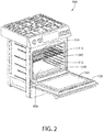
- Fig. 2 shows an example of an appliance 100 with door 120 in an open position to allow access to cooking chamber 200.
- Cooking chamber 200 has, in this example, side walls 210, a rear wall 220, and a bottom 230.
- the appliance shown in Fig. 2 has a heater cover panel 400 that covers a heater (for example a gas burner) located in cooking chamber 200 and below heater cover panel 400.
- heater cover panel 400 has two openings 410 that allow air to pass between a space below heater cover panel 400 and a space above heater cover panel 400.
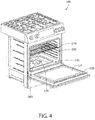
- Fig. 3 shows an exemplary embodiment of the invention that includes a heater pan 300 in the bottom 230 of appliance 100.
- Heater pan 300 is, in this embodiment, a recess into bottom 230 under a heater such as, for example, gas burner 310 shown in Fig. 4 .
- Gas burner 310 is just one example of a heater in accordance with embodiments of the invention.
- Other examples of heater 310 are electric resistive heating elements, infrared heaters, other electric heating elements, and other devices that generate heat to heat cooking chamber 200.
- Fig. 4 shows a single gas burner 310, other examples have two or more gas burners. Still other examples have one or more of the other types of heaters listed above. Particular embodiments can have any combination of any number of each type of heater.
- Heater cover panel 400 can be a metal panel that is provided to block a user's view of any heater provided under heater cover panel 400.
- the inventor of the current invention recognized a disadvantage of the opaque heater cover panel 400 shown in Fig. 2 . That disadvantage is that a user looking into the cooking chamber cannot tell if the heater is activated.
- a purpose of the opaque nature of heater cover panel 400 is to intentionally block the user's view of an unsightly burner.
- a purpose of the invention is to allow a user to see whether burner (or other heater) 310, for example, is activated (in this example, burning gas) when looking into the cooking chamber.
- burner or other heater 310 is visible simultaneously through both heater cover panel 500 and window 125 when door 120 is in the closed position.
- the cover panel 500 is designed to be a transparent oven bottom. As a result, a user can tell if burner or other heater 310 is activated without opening door 120.
- heater cover panel 500 being transparent is that it provides a distinguishing feature of appliances in accordance with the invention when compared to other appliances. For example, a distinctive shaped heater, such as burner 310, being visible to a user immediately identifies appliance 100 as a particular type, model, or brand of appliance.
- heater 310 can be shaped in custom designs such as words, letters, symbols, etc., as required by a user. Providing transparent heater cover panel 500 permits a user to see the custom design of heater 310.
- heater cover panel 500 has 0% opacity (100% transparency). In other embodiments, the opacity is more than 0% to create, for example, a smoked or other appearance. In some embodiments, opacity is at a level that obstructs view of heater 310 when heater 310 is not emitting any light, but allows heater 310 to be seen when heater 310 is emitting light (such as flames from a gas burner 310).
- heater cover panel 500 has a 0% opacity (100% transparency). In other embodiments, the opacity of heater cover panel 500 is more than 0% and less than 100% in order to allow a user to see heater 310 through heater cover panel 500 differently in different conditions. In particular embodiments, the opacity of heater cover panel 500 is between 5% and 95%. In particular embodiments, the opacity of heater cover panel 500 is between 10% and 80%. In particular embodiments, the opacity of heater cover panel 500 is between 20% and 50%. In particular embodiments, the opacity of heater cover panel 500 is between 20% and 30%. In some embodiments, the opacity is such that heater cover panel 500 is translucent such that heater 310 is not visible through heater cover panel 500, but light emitted from heater 310 is visible through heater cover panel 500.
- heater 310 is visible through heater cover panel 500 when heater 310 is producing heat (for example, burning gas in the case of a gas burner, and energized in the case of an electric heating element).
- heater 310 is not visible through heater cover panel 500 when heater 310 is not producing heat.
- the opacity of heater cover panel 500 is selected based on the desired visual appearance for these two conditions. For example, in an embodiment, heater cover panel 500 (such as a smoked ceramic glass) has an opacity of 20% and allows a user to see heater 310 when producing heat, but prevents the user from seeing heater 310 when not producing heat.
- heater 310 being a gas burner
- the flames of heater 310 can be seen through heater cove panel 500 due to the light emitted by the flames.
- heater 310 being an electric heating element
- the red (or other color) glow of heater 310 can be seen through heater cove panel 500 due to the light emitted by the electric heating element.
- heater cover panel 500 provides the benefit of a user being able to determine whether or not heater 310 is energized while also providing a solid surface to prevent drippings or other material produced by the food item being heated from contacting heater 310.
- Opaque oven bottom panels do not provide this advantage.
- Fig. 6 shows an example of heater cover panel 500 that is a solid piece of material and has two openings to allow air to pass between a space below heater cover panel 500 (where heater 310 is located) and a space above heater cover panel 500 (where a food item is placed for heating).
- heater cover panel 500 has an upper surface 510, a front edge 540, and side edges 530.
- heater cover panel 500 has a uniform thickness.
- heater cover panel 500 has different thicknesses at different locations. Varying thicknesses at different locations on heater cover panel 500 can promote air movement in a desired path, as explained in relation to Fig. 9 , below.
- Varying thicknesses at different locations on heater cover panel 500 can promote flame spread in a desired pattern in the case of one or more gas burners.
- the shape of the underside of heater cover panel 500 can be designed to promote the flames from one or more gas burners to spread into a predetermined pattern such as, for example, a brand-defining logo or name.
- Other examples have fewer or more openings than the number shown in Fig. 6.
- Fig. 7 shows an example of heater cover panel 500 that is a solid piece of material and has no openings.
- Embodiments of heater cover panel 500 are materials that can withstand temperatures generated by the particular heater 310 used in appliance 100. In some examples, this temperature is between 500 degrees C and 1000 degrees C.
- An example of materials that can be used for heater cover panel 500 is ceramic glass. Other transparent or translucent materials that can withstand the temperatures generated by the particular heater 310 can also be used.
- Fig. 8 shows a cross-sectional view of heater cover panel 500 shown in Fig. 7 .
- this example of heater cover panel 500 is solid and has a uniform thickness between upper surface 510 and a lower surface 520.
- a uniform thickness as shown in Fig. 8 provides a less distorted view of heater 310 from above heater cover panel 500 than a heater cover panel having a thickness that is not uniform.
- Fig. 9 shows an example of a cross-section of a heater cover panel 500' that has a thickness that is not uniform.
- an upper surface 510' is planar and horizontal.
- upper surface 510' includes one or more planar surface and/or one or more non-planar surfaces.
- the bottom surface of heater cover panel 500' has two sloped surfaces 522, 524 that meet at an edge 526 that is a straight line.
- Other examples have the same number or a larger number of surfaces that are planar or non-planar and intersect at various locations on the bottom surface of heater cover panel 500'.
- Sloped surfaces 522, 524 of the example shown in Fig. 9 promote the flow of hot gases produced by (or heated by) heater 310 toward outer edges of heater cover panel 500'.
- one or more gaps are provided between the edges of heater cover panel 500, 500' and the cooking chamber walls/bottom to allow gases to pass between these spaces.
- Some embodiments include both one or more openings in heater cover panel 500, 500' and one or more gaps at the edges of heater cover panel 500, 500'.
- Some embodiments use heaters that do not require any venting between the space in which the heater is located and the cooking chamber, such as, for example, some electric heating elements. Some of these embodiments do not provide a fluid connection between these two spaces. For example, they do not have any openings in heater cover panel 500, 500' and do not have any gaps at the edges of heater cover panel 500, 500'.
- Transparent heater cover panel 500, 500' provides the benefit of allowing heater 310 to be viewed by a user while also providing a surface to prevent drippings and other material from the item being heated from contacting the heater. This simplifies cleaning the appliance by avoiding the need to clean around a complex-shaped heater 310.
Landscapes
- Engineering & Computer Science (AREA)
- Chemical & Material Sciences (AREA)
- Combustion & Propulsion (AREA)
- Mechanical Engineering (AREA)
- General Engineering & Computer Science (AREA)
- Electric Stoves And Ranges (AREA)
- Baking, Grill, Roasting (AREA)
Abstract
Description
- The invention is directed to heater cover panel according to the preamble of claim 1 as well as to a domestic cooking appliance according to the preamble of claim 10..
- Some modern domestic kitchens include cooking appliances such as ovens and ranges that have one or more heaters that provide the heat for cooking a food item in the appliance. The heater(s) can be, for example, gas burners, electric heating elements, or other heat producing devices. In some of these appliances, a heater located at the bottom of a cooking chamber of the appliance is covered by an opaque panel.
- Applicants recognized an improvement to the above arrangement and implement that improvement in embodiments of the invention.
- Starting from the disadvantages and shortcomings as described above and taking the prior art as discussed into account, an object of the present invention is to further develop a heater cover panel as described in the technical field as well as a domestic cooking appliance of the kind as described in the technical field, in such way that the heater is visible through the heater cover panel.
- The object of the present invention is achieved by a heater cover panel comprising the features of claim 1 as well as by an domestic cooking appliance comprising the features of claim 10. Advantageous embodiments and expedient improvements of the present invention are disclosed in the respective dependent claims.
- The invention achieves the benefit of providing a user of the appliance with the ability to see the heater in the bottom of the cooking chamber. This benefit is achieved by providing a heater cover panel, in particular an oven bottom, that is transparent or translucent so that the user can see whether the heater is producing heat (for example, burning gas in the case of a gas burner, or electrically energized in the case of an electric heating element). A transparent or translucent heater cover panel provides the above benefit while also protecting the heater from drippings or other material separated from the food item and providing an easily cleanable surface.
- With other words, embodiments of the invention are directed to a bottom panel of an oven that allows a bottom burner to be seen through the bottom panel.
- Particular embodiments of the invention are directed to a domestic cooking appliance for heating a food item. The appliance includes a main housing; a cooking chamber located in the main housing and configured to receive the food item, the cooking chamber having side panels, and a back panel; a heater cover panel located in a lower region of the cooking chamber, the heater cover panel being one of translucent and transparent; and a heater that produces heat for heating the cooking chamber, the heater being located below the heater cover panel. The heater is visible through the heater cover panel.
- In some embodiments, an area below the heater cover panel and an area above the heater cover panel are fluidly connected, the area below the heater cover panel and the area above the heater cover panel are both in the cooking chamber, and the heater is located in the area below the heater cover panel.
- In some embodiments, the appliance has an openable door that permits access to the cooking chamber when the door is in an open position, the door having a transparent window that allows viewing of the cooking chamber when the door is in a closed position. The heater is visible through the window when the heater is producing heat and the heater cover panel is in an operating position.
- Other embodiments of the invention are directed to a domestic cooking appliance for heating a food item. The appliance having a main housing; a cooking chamber located in the main housing and configured to receive the food item; a transparent burner cover panel located in a lower region of the cooking chamber; and a gas burner that produces heat for heating the cooking chamber, the gas burner being located below the burner cover panel. Flames produced by the gas burner are visible through the burner cover panel when the burner is burning gas.
- In some embodiments, the burner cover panel has an opacity of between 20% and 30%.
- According to a preferred embodiment of the present invention the heater can be a gas burner. Advantageously, flames produced by the gas burner (310) are visible through the burner cover panel (500; 500') when the burner (310) is burning gas.
- According to an alternative preferred embodiment of the present invention the heater can be an electric heating element.
- In some embodiments, the domestic cooking appliance further comprises an openable door that permits access to the cooking chamber when the door is in an open position, the door having a transparent window that allows viewing of the cooking chamber when the door is in a closed position. The flames produced by the gas burner are visible through the window when the burner is burning gas and the burner cover panel is in an operating position.
- An example of an application for the invention is a domestic kitchen gas oven having a gas burner located below a transparent bottom panel of the cooking compartment of the oven.
- The following figures form part of the present specification and are included to further demonstrate certain aspects of the disclosed features and functions, and should not be used to limit or define the disclosed features and functions. Consequently, a more complete understanding of the exemplary embodiments and further features and advantages thereof may be acquired by referring to the following description taken in conjunction with the accompanying drawings, wherein:
-
Figure 1 is a perspective schematic view of an exemplary appliance in accordance with embodiments of the invention; -
Figure 2 is a perspective schematic view of an appliance; -
Figure 3 is a perspective schematic view of an exemplary appliance in accordance with embodiments of the invention with the door in an open position; -
Figure 4 is a perspective schematic view of an exemplary appliance in accordance with embodiments of the invention with the door in an open position; -
Figure 5 is a perspective schematic view of an exemplary appliance in accordance with embodiments of the invention with the door in an open position; -
Figure 6 is a perspective schematic view of an exemplary heater cover panel in accordance with embodiments of the invention; -
Figure 7 is a perspective schematic view of an exemplary heater cover panel in accordance with embodiments of the invention; -
Figure 8 is a sectional view of a heater cover panel in accordance with embodiments of the invention; and -
Figure 9 is a sectional view of a heater cover panel in accordance with embodiments of the invention. - In order to avoid unnecessary repetitions, the following description regarding the embodiments, characteristics and advantages of the present invention relates (unless stated otherwise)
- to the embodiment of the
domestic cooking appliance 100 according to the present invention (cf.Figs. 1 to 5 ) as well as - to the first embodiment of the translucent and/or transparent
heater cover panel 500 according to the present invention (cf.Figures 5 to 8 ) as well as - to the second embodiment of the translucent and/or transparent heater cover panel 500'according to the present invention (cf.
Figure 9 ). - The invention is described herein with reference to the accompanying drawings in which exemplary embodiments of the invention are shown. The invention may, however, be embodied in many different forms and should not be construed as limited to the embodiments set forth herein.
- As explained above, embodiments of the invention provide an improvement to a domestic oven or other cooking appliance.
-
Fig. 1 shows an example of adomestic home appliance 100 in accordance with embodiments of the invention. In this example,appliance 100 has anupper cooking section 140 havingmultiple gas burners 145, acontrol panel 130, ahousing 110, and adoor 120.Door 120 has ahandle 122 and atransparent window 125. Window 125 allows a user to see into a cooking chamber 200 (Fig. 3 ) whendoor 120 is in a closed position. -
Fig. 2 shows an example of anappliance 100 withdoor 120 in an open position to allow access tocooking chamber 200.Cooking chamber 200 has, in this example,side walls 210, arear wall 220, and abottom 230. The appliance shown inFig. 2 has aheater cover panel 400 that covers a heater (for example a gas burner) located incooking chamber 200 and belowheater cover panel 400. In this example,heater cover panel 400 has twoopenings 410 that allow air to pass between a space belowheater cover panel 400 and a space aboveheater cover panel 400. -
Fig. 3 shows an exemplary embodiment of the invention that includes aheater pan 300 in thebottom 230 ofappliance 100.Heater pan 300 is, in this embodiment, a recess intobottom 230 under a heater such as, for example,gas burner 310 shown inFig. 4 .Gas burner 310 is just one example of a heater in accordance with embodiments of the invention. Other examples ofheater 310 are electric resistive heating elements, infrared heaters, other electric heating elements, and other devices that generate heat to heatcooking chamber 200. WhileFig. 4 shows asingle gas burner 310, other examples have two or more gas burners. Still other examples have one or more of the other types of heaters listed above. Particular embodiments can have any combination of any number of each type of heater. - As shown in
Fig. 2 , some domestic cooking appliances have an opaque heater cover panel such asheater cover panel 400.Heater cover panel 400 can be a metal panel that is provided to block a user's view of any heater provided underheater cover panel 400. - The inventor of the current invention recognized a disadvantage of the opaque
heater cover panel 400 shown inFig. 2 . That disadvantage is that a user looking into the cooking chamber cannot tell if the heater is activated. A purpose of the opaque nature ofheater cover panel 400 is to intentionally block the user's view of an unsightly burner. A purpose of the invention is to allow a user to see whether burner (or other heater) 310, for example, is activated (in this example, burning gas) when looking into the cooking chamber. In embodiments that havetransparent window 125 indoor 120, burner orother heater 310 is visible simultaneously through bothheater cover panel 500 andwindow 125 whendoor 120 is in the closed position. Thecover panel 500 is designed to be a transparent oven bottom. As a result, a user can tell if burner orother heater 310 is activated without openingdoor 120. - In some embodiments, another advantage of
heater cover panel 500 being transparent is that it provides a distinguishing feature of appliances in accordance with the invention when compared to other appliances. For example, a distinctive shaped heater, such asburner 310, being visible to a user immediately identifiesappliance 100 as a particular type, model, or brand of appliance. In addition,heater 310 can be shaped in custom designs such as words, letters, symbols, etc., as required by a user. Providing transparentheater cover panel 500 permits a user to see the custom design ofheater 310. - In embodiments,
heater cover panel 500 has 0% opacity (100% transparency). In other embodiments, the opacity is more than 0% to create, for example, a smoked or other appearance. In some embodiments, opacity is at a level that obstructs view ofheater 310 whenheater 310 is not emitting any light, but allowsheater 310 to be seen whenheater 310 is emitting light (such as flames from a gas burner 310). - Opacity of a medium is defined according to the formula:

- x = the distance the light has traveled through the medium,
- I(x) = the intensity of light remaining at distance x, and
- I0 = the initial intensity of light, at x = 0.
- In some embodiments of the invention,
heater cover panel 500 has a 0% opacity (100% transparency). In other embodiments, the opacity ofheater cover panel 500 is more than 0% and less than 100% in order to allow a user to seeheater 310 throughheater cover panel 500 differently in different conditions. In particular embodiments, the opacity ofheater cover panel 500 is between 5% and 95%. In particular embodiments, the opacity ofheater cover panel 500 is between 10% and 80%. In particular embodiments, the opacity ofheater cover panel 500 is between 20% and 50%. In particular embodiments, the opacity ofheater cover panel 500 is between 20% and 30%. In some embodiments, the opacity is such thatheater cover panel 500 is translucent such thatheater 310 is not visible throughheater cover panel 500, but light emitted fromheater 310 is visible throughheater cover panel 500. - In particular embodiments,
heater 310 is visible throughheater cover panel 500 whenheater 310 is producing heat (for example, burning gas in the case of a gas burner, and energized in the case of an electric heating element). In some embodiments whereheater 310 is visible throughheater cover panel 500 whenheater 310 is producing heat,heater 310 is not visible throughheater cover panel 500 whenheater 310 is not producing heat. The opacity ofheater cover panel 500 is selected based on the desired visual appearance for these two conditions. For example, in an embodiment, heater cover panel 500 (such as a smoked ceramic glass) has an opacity of 20% and allows a user to seeheater 310 when producing heat, but prevents the user from seeingheater 310 when not producing heat. In the case ofheater 310 being a gas burner, the flames ofheater 310 can be seen throughheater cove panel 500 due to the light emitted by the flames. In the case ofheater 310 being an electric heating element, the red (or other color) glow ofheater 310 can be seen throughheater cove panel 500 due to the light emitted by the electric heating element. - The ability of a user to see
heater 310 throughheater cover panel 500 provides the benefit of a user being able to determine whether or notheater 310 is energized while also providing a solid surface to prevent drippings or other material produced by the food item being heated from contactingheater 310. Opaque oven bottom panels do not provide this advantage. -
Fig. 6 shows an example ofheater cover panel 500 that is a solid piece of material and has two openings to allow air to pass between a space below heater cover panel 500 (whereheater 310 is located) and a space above heater cover panel 500 (where a food item is placed for heating). In this example,heater cover panel 500 has anupper surface 510, afront edge 540, and side edges 530. In this example,heater cover panel 500 has a uniform thickness. In other examples,heater cover panel 500 has different thicknesses at different locations. Varying thicknesses at different locations onheater cover panel 500 can promote air movement in a desired path, as explained in relation toFig. 9 , below. Varying thicknesses at different locations onheater cover panel 500 can promote flame spread in a desired pattern in the case of one or more gas burners. For example, the shape of the underside ofheater cover panel 500 can be designed to promote the flames from one or more gas burners to spread into a predetermined pattern such as, for example, a brand-defining logo or name. Other examples have fewer or more openings than the number shown inFig. 6. Fig. 7 shows an example ofheater cover panel 500 that is a solid piece of material and has no openings. - Embodiments of
heater cover panel 500 are materials that can withstand temperatures generated by theparticular heater 310 used inappliance 100. In some examples, this temperature is between 500 degrees C and 1000 degrees C. An example of materials that can be used forheater cover panel 500 is ceramic glass. Other transparent or translucent materials that can withstand the temperatures generated by theparticular heater 310 can also be used. -
Fig. 8 shows a cross-sectional view ofheater cover panel 500 shown inFig. 7 . As can be seen fromFig. 8 , this example ofheater cover panel 500 is solid and has a uniform thickness betweenupper surface 510 and alower surface 520. In some embodiments, a uniform thickness as shown inFig. 8 provides a less distorted view ofheater 310 from aboveheater cover panel 500 than a heater cover panel having a thickness that is not uniform. -
Fig. 9 shows an example of a cross-section of a heater cover panel 500' that has a thickness that is not uniform. In this example, an upper surface 510' is planar and horizontal. In other examples, upper surface 510' includes one or more planar surface and/or one or more non-planar surfaces. In this example, the bottom surface of heater cover panel 500' has two slopedsurfaces edge 526 that is a straight line. Other examples have the same number or a larger number of surfaces that are planar or non-planar and intersect at various locations on the bottom surface of heater cover panel 500'. - Sloped surfaces 522, 524 of the example shown in
Fig. 9 promote the flow of hot gases produced by (or heated by)heater 310 toward outer edges of heater cover panel 500'. In some embodiments (such as those having a gas burner 310) that require venting between the spaces above and belowheater cover panel 500, 500' and haveheater cover panels 500, 500' that have no openings, one or more gaps are provided between the edges ofheater cover panel 500, 500' and the cooking chamber walls/bottom to allow gases to pass between these spaces. Some embodiments include both one or more openings inheater cover panel 500, 500' and one or more gaps at the edges ofheater cover panel 500, 500'. - Some embodiments use heaters that do not require any venting between the space in which the heater is located and the cooking chamber, such as, for example, some electric heating elements. Some of these embodiments do not provide a fluid connection between these two spaces. For example, they do not have any openings in
heater cover panel 500, 500' and do not have any gaps at the edges ofheater cover panel 500, 500'. - Transparent
heater cover panel 500, 500' provides the benefit of allowingheater 310 to be viewed by a user while also providing a surface to prevent drippings and other material from the item being heated from contacting the heater. This simplifies cleaning the appliance by avoiding the need to clean around a complex-shapedheater 310. - It will be appreciated that variants of the above-disclosed and other features and functions, or alternatives thereof, may be combined into many other different systems or applications. Any of the features described above can be combined with any other feature described above as long as the combined features are not mutually exclusive. Various presently unforeseen or unanticipated alternatives, modifications, variations or improvements therein may be subsequently made by those skilled in the art which are also intended to be encompassed by the invention.
-
- 100 domestic home appliance, in particular domestic cooking appliance
- 110 housing, in particular main housing
- 120 door
- 122 handle of the
door 120 - 125 transparent window of the
door 120 - 130 control panel
- 140 upper cooking section
- 145 gas burners of the
upper cooking section 140 - 200 cooking chamber
- 210 side panel, in particular side wall of the
cooking chamber 200 - 220 back panel, in particular rear wall of the
cooking chamber 200 - 230 bottom of the
cooking chamber 200 - 300 heater pan
- 310 heater, in particular gas burner, electric heating element, electric resistive heating element and/or infrared heater
- 400 opaque heater cover panel (cf.
Figure 2 ) - 410 openings of the
heater cover panel 400 that allow air to pass between a space belowheater cover panel 400 and a space aboveheater cover panel 400 - 500 translucent and/or transparent heater cover panel, in particular burner cover panel, for example transparent oven bottom, (first embondiment cf.
Figures 5 to 8 ) - 500' translucent and/or transparent heater cover panel, in particular burner cover panel, for example transparent oven bottom, (second embodiment cf.
Figure 9 ) - 510 upper surface of heater cover panel 500 (cf.
Figures 6 to 8 ) - 510' upper surface of heater cover panel 500' (cf.
Figure 9 ) - 520 lower surface or bottom surface of heater cover panel 500 (cf.
Figure 8 ) - 522 first sloped surface of heater cover panel 500' (cf.
Figure 9 ) - 524 further sloped surface, in particular second sloped surface, of heater cover panel 500' (cf.
Figure 9 ) - 526 edge of
bottom surface 520 of heater cover panel 500' (cf.Figure 9 ) - 530 side edge of heater cover panel 500 (cf.
Figures 6 to 8 ) - 530' side edge of heater cover panel 500' (cf.
Figure 9 ) - 540 front edge of heater cover panel 500 (cf.
Figure 6 )
Claims (15)
- A heater cover panel (500; 500')- locatable in a lower region of the cooking chamber (200) of a domestic cooking appliance (100) and- being designed to cover a heater (310) when the heater cover panel (500; 500') is in an operating position, wherein the heater (310) is designed to produce heat for heating a cooking chamber (200) of the domestic cooking appliance (100),
characterized by
the heater cover panel (500; 500') being one of translucent and transparent. - The heater cover panel of claim 1, wherein the heater cover panel (500; 500') is a glass ceramic.
- The heater cover panel of claim 1 or 2, wherein the heater cover panel (500; 500') has an air passage through which air can pass between the area below the heater cover panel (500; 500') and the area above the heater cover panel (500; 500').
- The heater cover panel of at least one of claims 1 to 3, wherein the heater cover panel (500; 500') has an opening that fluidly connects the area below the heater cover panel (500; 500') and the area above the heater cover panel (500; 500').
- The heater cover panel of at least one of claims 1 to 4, wherein the heater cover panel (500; 500') has an opacity of between 20% and 30%.
- The heater cover panel of at least one of claims 1 to 5, wherein the heater cover panel (500; 500') has a bottom surface (520) that includes a first non-horizontal sloped surface when installed in the domestic cooking appliance (100).
- The heater cover panel of claim 6, wherein the bottom surface (520) of the heater cover panel (500; 500') has a second sloped surface (524) that intersects the first sloped surface (522) at a positive angle.
- The heater cover panel of claim 7, wherein the bottom surface (520) of the heater cover panel (500; 500') has a lowest point formed by a line at the intersection of the first sloped surface (522) and the second sloped surface (524) when installed in the domestic cooking appliance (100), the first sloped surface (522) and the second sloped surface (524) angling upward away from the intersection line.
- The domestic cooking appliance of at least one of claims 1 to 5, wherein the heater cover panel (500; 500') has a horizontal bottom surface (520) when installed in the domestic cooking appliance (100).
- A domestic cooking appliance (100) for heating a food item, comprising:a main housing (110);a cooking chamber (200) located in the main housing (110) and configured to receive the food item, the cooking chamber (200) having side panels (210), and a back panel (220);a heater cover panel (500; 500') located in a lower region of the cooking chamber (200), anda heater (310) that produces heat for heating the cooking chamber (200), theheater (310) being located below the heater cover panel (500; 500'),characterized by- the heater cover panel (500; 500') being a heater cover panel (500; 500') according to at least one of claims 1 to 9; and- the heater (310) being visible through the heater cover panel (500; 500').
- The domestic cooking appliance of claim 10, wherein the heater cover panel (500; 500') is located above the heater (310) at every part of the heater.
- The domestic cooking appliance of claims 10 or 11, wherein an area below the heater cover panel (500; 500') and an area above the heater cover panel (500; 500') are fluidly connected,
the area below the heater cover panel (500; 500') and the area above the heater cover panel (500; 500') are both in the cooking chamber (200), and
the heater (310) is located in the area below the heater cover panel (500; 500'). - The domestic cooking appliance of at least one of claims 10 to 12, wherein an air gap exists between an edge of the heater cover panel (500; 500') and one of the group consisting of a first one of the cooking chamber (200) side panels (210), a second one of the cooking chamber side panels (210), and the cooking chamber back panel (220).
- The domestic cooking appliance of at least one of claims 10 to 13, further comprising an openable door (120) that permits access to the cooking chamber (200) when the door (120) is in an open position, the door (120) having a transparent window (125) that allows viewing of the cooking chamber (200) when the door (120) is in a closed position,
wherein the heater (310) is visible through the window (125) when the heater (310) is producing heat and the heater cover panel (500; 500') is in an operating position. - A domestic cooking appliance of at least one of claims 10 to 14, wherein
the heater (310) is a gas burner,
wherein flames produced by the gas burner are visible through the burner cover panel (500; 500') when the burner is burning gas.
Applications Claiming Priority (1)
| Application Number | Priority Date | Filing Date | Title |
|---|---|---|---|
| US16/452,575 US20200408416A1 (en) | 2019-06-26 | 2019-06-26 | Transparent oven bottom |
Publications (1)
| Publication Number | Publication Date |
|---|---|
| EP3795905A1 true EP3795905A1 (en) | 2021-03-24 |
Family
ID=71096587
Family Applications (1)
| Application Number | Title | Priority Date | Filing Date |
|---|---|---|---|
| EP20180004.2A Withdrawn EP3795905A1 (en) | 2019-06-26 | 2020-06-15 | Transparent oven bottom |
Country Status (2)
| Country | Link |
|---|---|
| US (1) | US20200408416A1 (en) |
| EP (1) | EP3795905A1 (en) |
Citations (6)
| Publication number | Priority date | Publication date | Assignee | Title |
|---|---|---|---|---|
| US5726423A (en) * | 1988-05-19 | 1998-03-10 | Quadlux, Inc. | Apparatus and method for regulating cooking time in a radiant energy oven |
| US20020157659A1 (en) * | 2001-04-26 | 2002-10-31 | Rummel Randy L. | Gas broiler |
| US6831255B1 (en) * | 2003-09-11 | 2004-12-14 | Maytag Corporation | Combination radiant/convection cooking system for an electric oven |
| US6949720B1 (en) * | 2004-04-01 | 2005-09-27 | Distintive Applicances, Inc. | Bottom electric heating element system for ovens |
| CA2475035C (en) * | 2003-09-11 | 2009-12-15 | Maytag Corporation | Combination radiant/convection gas cooking appliance |
| EP3205941A1 (en) * | 2014-10-10 | 2017-08-16 | Panasonic Intellectual Property Management Co., Ltd. | Heating cooker |
Family Cites Families (4)
| Publication number | Priority date | Publication date | Assignee | Title |
|---|---|---|---|---|
| US6861255B1 (en) * | 2001-07-18 | 2005-03-01 | Sea Run Holdings, Inc. | Method of using fish plasma components for tissue culture |
| US6894252B2 (en) * | 2003-04-10 | 2005-05-17 | Premark Feg L.L.C. | Dough proofing apparatus and related methods |
| EP2757319B1 (en) * | 2013-01-21 | 2020-03-11 | BSH Hausgeräte GmbH | Domestic appliance |
| US10634362B2 (en) * | 2016-06-30 | 2020-04-28 | Midea Group Co., Ltd. | Oven bottom with cooking surface |
-
2019
- 2019-06-26 US US16/452,575 patent/US20200408416A1/en not_active Abandoned
-
2020
- 2020-06-15 EP EP20180004.2A patent/EP3795905A1/en not_active Withdrawn
Patent Citations (6)
| Publication number | Priority date | Publication date | Assignee | Title |
|---|---|---|---|---|
| US5726423A (en) * | 1988-05-19 | 1998-03-10 | Quadlux, Inc. | Apparatus and method for regulating cooking time in a radiant energy oven |
| US20020157659A1 (en) * | 2001-04-26 | 2002-10-31 | Rummel Randy L. | Gas broiler |
| US6831255B1 (en) * | 2003-09-11 | 2004-12-14 | Maytag Corporation | Combination radiant/convection cooking system for an electric oven |
| CA2475035C (en) * | 2003-09-11 | 2009-12-15 | Maytag Corporation | Combination radiant/convection gas cooking appliance |
| US6949720B1 (en) * | 2004-04-01 | 2005-09-27 | Distintive Applicances, Inc. | Bottom electric heating element system for ovens |
| EP3205941A1 (en) * | 2014-10-10 | 2017-08-16 | Panasonic Intellectual Property Management Co., Ltd. | Heating cooker |
Also Published As
| Publication number | Publication date |
|---|---|
| US20200408416A1 (en) | 2020-12-31 |
Similar Documents
| Publication | Publication Date | Title |
|---|---|---|
| JP4684242B2 (en) | Cooker | |
| EP3640545B1 (en) | Griddle device | |
| US8978637B2 (en) | Top burner and cooker comprising the same | |
| US10634362B2 (en) | Oven bottom with cooking surface | |
| CA2459597A1 (en) | Air-inlet assembly for a gas cooking appliance | |
| JP4679653B2 (en) | Cooker | |
| EP4050265B1 (en) | Cooking appliance | |
| US20200408416A1 (en) | Transparent oven bottom | |
| JP6071975B2 (en) | Stove | |
| JP2003050033A (en) | Range hood fan | |
| JP4687394B2 (en) | Gas stove | |
| JP4679652B2 (en) | Cooker | |
| JP4444769B2 (en) | Drop-in gas stove | |
| JP4115424B2 (en) | Stove top and stove | |
| JP5225395B2 (en) | Cooker | |
| JP6560916B2 (en) | Stove | |
| JP2017116109A (en) | Cooking stove | |
| JP6670158B2 (en) | Gas burner | |
| EP4001776B1 (en) | Cooking appliance having a flue | |
| US20250084991A1 (en) | Gas burner assembly for a cooktop appliance | |
| EP0341220B1 (en) | Appliance for cooking food with an easier indication of the correspondence between burners and control knobs | |
| KR100777264B1 (en) | Gas oven range exhaust structure | |
| KR101690329B1 (en) | Cooking appliance | |
| JP2006002951A (en) | Drop-in type gas cookstove | |
| KR20110137442A (en) | Cooker |
Legal Events
| Date | Code | Title | Description |
|---|---|---|---|
| PUAI | Public reference made under article 153(3) epc to a published international application that has entered the european phase |
Free format text: ORIGINAL CODE: 0009012 |
|
| STAA | Information on the status of an ep patent application or granted ep patent |
Free format text: STATUS: THE APPLICATION HAS BEEN PUBLISHED |
|
| AK | Designated contracting states |
Kind code of ref document: A1 Designated state(s): AL AT BE BG CH CY CZ DE DK EE ES FI FR GB GR HR HU IE IS IT LI LT LU LV MC MK MT NL NO PL PT RO RS SE SI SK SM TR |
|
| AX | Request for extension of the european patent |
Extension state: BA ME |
|
| STAA | Information on the status of an ep patent application or granted ep patent |
Free format text: STATUS: REQUEST FOR EXAMINATION WAS MADE |
|
| 17P | Request for examination filed |
Effective date: 20210924 |
|
| RBV | Designated contracting states (corrected) |
Designated state(s): AL AT BE BG CH CY CZ DE DK EE ES FI FR GB GR HR HU IE IS IT LI LT LU LV MC MK MT NL NO PL PT RO RS SE SI SK SM TR |
|
| STAA | Information on the status of an ep patent application or granted ep patent |
Free format text: STATUS: EXAMINATION IS IN PROGRESS |
|
| 17Q | First examination report despatched |
Effective date: 20230915 |
|
| GRAP | Despatch of communication of intention to grant a patent |
Free format text: ORIGINAL CODE: EPIDOSNIGR1 |
|
| STAA | Information on the status of an ep patent application or granted ep patent |
Free format text: STATUS: GRANT OF PATENT IS INTENDED |
|
| INTG | Intention to grant announced |
Effective date: 20240415 |
|
| STAA | Information on the status of an ep patent application or granted ep patent |
Free format text: STATUS: THE APPLICATION IS DEEMED TO BE WITHDRAWN |
|
| 18D | Application deemed to be withdrawn |
Effective date: 20240817 |