EP3795809B1 - Exhaust purification device - Google Patents
Exhaust purification device Download PDFInfo
- Publication number
- EP3795809B1 EP3795809B1 EP19803412.6A EP19803412A EP3795809B1 EP 3795809 B1 EP3795809 B1 EP 3795809B1 EP 19803412 A EP19803412 A EP 19803412A EP 3795809 B1 EP3795809 B1 EP 3795809B1
- Authority
- EP
- European Patent Office
- Prior art keywords
- inner cylinder
- end portion
- exhaust gas
- purification device
- base portion
- Prior art date
- Legal status (The legal status is an assumption and is not a legal conclusion. Google has not performed a legal analysis and makes no representation as to the accuracy of the status listed.)
- Active
Links
Images



Classifications
-
- F—MECHANICAL ENGINEERING; LIGHTING; HEATING; WEAPONS; BLASTING
- F01—MACHINES OR ENGINES IN GENERAL; ENGINE PLANTS IN GENERAL; STEAM ENGINES
- F01N—GAS-FLOW SILENCERS OR EXHAUST APPARATUS FOR MACHINES OR ENGINES IN GENERAL; GAS-FLOW SILENCERS OR EXHAUST APPARATUS FOR INTERNAL-COMBUSTION ENGINES
- F01N3/00—Exhaust or silencing apparatus having means for purifying, rendering innocuous, or otherwise treating exhaust
- F01N3/08—Exhaust or silencing apparatus having means for purifying, rendering innocuous, or otherwise treating exhaust for rendering innocuous
- F01N3/10—Exhaust or silencing apparatus having means for purifying, rendering innocuous, or otherwise treating exhaust for rendering innocuous by thermal or catalytic conversion of noxious components of exhaust
- F01N3/24—Exhaust or silencing apparatus having means for purifying, rendering innocuous, or otherwise treating exhaust for rendering innocuous by thermal or catalytic conversion of noxious components of exhaust characterised by constructional aspects of converting apparatus
- F01N3/28—Construction of catalytic reactors
- F01N3/2839—Arrangements for mounting catalyst support in housing, e.g. with means for compensating thermal expansion or vibration
- F01N3/2842—Arrangements for mounting catalyst support in housing, e.g. with means for compensating thermal expansion or vibration specially adapted for monolithic supports, e.g. of honeycomb type
-
- F—MECHANICAL ENGINEERING; LIGHTING; HEATING; WEAPONS; BLASTING
- F01—MACHINES OR ENGINES IN GENERAL; ENGINE PLANTS IN GENERAL; STEAM ENGINES
- F01N—GAS-FLOW SILENCERS OR EXHAUST APPARATUS FOR MACHINES OR ENGINES IN GENERAL; GAS-FLOW SILENCERS OR EXHAUST APPARATUS FOR INTERNAL-COMBUSTION ENGINES
- F01N13/00—Exhaust or silencing apparatus characterised by constructional features
- F01N13/08—Other arrangements or adaptations of exhaust conduits
-
- F—MECHANICAL ENGINEERING; LIGHTING; HEATING; WEAPONS; BLASTING
- F01—MACHINES OR ENGINES IN GENERAL; ENGINE PLANTS IN GENERAL; STEAM ENGINES
- F01N—GAS-FLOW SILENCERS OR EXHAUST APPARATUS FOR MACHINES OR ENGINES IN GENERAL; GAS-FLOW SILENCERS OR EXHAUST APPARATUS FOR INTERNAL-COMBUSTION ENGINES
- F01N13/00—Exhaust or silencing apparatus characterised by constructional features
- F01N13/14—Exhaust or silencing apparatus characterised by constructional features having thermal insulation
-
- F—MECHANICAL ENGINEERING; LIGHTING; HEATING; WEAPONS; BLASTING
- F01—MACHINES OR ENGINES IN GENERAL; ENGINE PLANTS IN GENERAL; STEAM ENGINES
- F01N—GAS-FLOW SILENCERS OR EXHAUST APPARATUS FOR MACHINES OR ENGINES IN GENERAL; GAS-FLOW SILENCERS OR EXHAUST APPARATUS FOR INTERNAL-COMBUSTION ENGINES
- F01N13/00—Exhaust or silencing apparatus characterised by constructional features
- F01N13/14—Exhaust or silencing apparatus characterised by constructional features having thermal insulation
- F01N13/141—Double-walled exhaust pipes or housings
- F01N13/145—Double-walled exhaust pipes or housings with a gas other than air filling the space between both walls
-
- F—MECHANICAL ENGINEERING; LIGHTING; HEATING; WEAPONS; BLASTING
- F01—MACHINES OR ENGINES IN GENERAL; ENGINE PLANTS IN GENERAL; STEAM ENGINES
- F01N—GAS-FLOW SILENCERS OR EXHAUST APPARATUS FOR MACHINES OR ENGINES IN GENERAL; GAS-FLOW SILENCERS OR EXHAUST APPARATUS FOR INTERNAL-COMBUSTION ENGINES
- F01N3/00—Exhaust or silencing apparatus having means for purifying, rendering innocuous, or otherwise treating exhaust
- F01N3/08—Exhaust or silencing apparatus having means for purifying, rendering innocuous, or otherwise treating exhaust for rendering innocuous
- F01N3/10—Exhaust or silencing apparatus having means for purifying, rendering innocuous, or otherwise treating exhaust for rendering innocuous by thermal or catalytic conversion of noxious components of exhaust
- F01N3/24—Exhaust or silencing apparatus having means for purifying, rendering innocuous, or otherwise treating exhaust for rendering innocuous by thermal or catalytic conversion of noxious components of exhaust characterised by constructional aspects of converting apparatus
- F01N3/28—Construction of catalytic reactors
-
- F—MECHANICAL ENGINEERING; LIGHTING; HEATING; WEAPONS; BLASTING
- F01—MACHINES OR ENGINES IN GENERAL; ENGINE PLANTS IN GENERAL; STEAM ENGINES
- F01N—GAS-FLOW SILENCERS OR EXHAUST APPARATUS FOR MACHINES OR ENGINES IN GENERAL; GAS-FLOW SILENCERS OR EXHAUST APPARATUS FOR INTERNAL-COMBUSTION ENGINES
- F01N3/00—Exhaust or silencing apparatus having means for purifying, rendering innocuous, or otherwise treating exhaust
- F01N3/08—Exhaust or silencing apparatus having means for purifying, rendering innocuous, or otherwise treating exhaust for rendering innocuous
- F01N3/10—Exhaust or silencing apparatus having means for purifying, rendering innocuous, or otherwise treating exhaust for rendering innocuous by thermal or catalytic conversion of noxious components of exhaust
- F01N3/24—Exhaust or silencing apparatus having means for purifying, rendering innocuous, or otherwise treating exhaust for rendering innocuous by thermal or catalytic conversion of noxious components of exhaust characterised by constructional aspects of converting apparatus
- F01N3/28—Construction of catalytic reactors
- F01N3/2839—Arrangements for mounting catalyst support in housing, e.g. with means for compensating thermal expansion or vibration
- F01N3/2853—Arrangements for mounting catalyst support in housing, e.g. with means for compensating thermal expansion or vibration using mats or gaskets between catalyst body and housing
-
- F—MECHANICAL ENGINEERING; LIGHTING; HEATING; WEAPONS; BLASTING
- F01—MACHINES OR ENGINES IN GENERAL; ENGINE PLANTS IN GENERAL; STEAM ENGINES
- F01N—GAS-FLOW SILENCERS OR EXHAUST APPARATUS FOR MACHINES OR ENGINES IN GENERAL; GAS-FLOW SILENCERS OR EXHAUST APPARATUS FOR INTERNAL-COMBUSTION ENGINES
- F01N2260/00—Exhaust treating devices having provisions not otherwise provided for
- F01N2260/08—Exhaust treating devices having provisions not otherwise provided for for preventing heat loss or temperature drop, using other means than layers of heat-insulating material
Definitions
- the present invention relates to an exhaust purification device provided in an exhaust path of an automobile.
- the exhaust purification device disclosed in this patent document 1 is an adiabatic exhaust flow pipe which comprises an inner cylinder and an outer cylinder provided on an outer periphery of the inner cylinder, wherein the inner cylinder and the outer cylinder are circumferentially welded at each of one end portion and the other end portion, the outer peripheral surface of the inner cylinder and the inner peripheral surface of the outer cylinder are spaced to form a gap between one end portion and the other end portion, and this gap constitutes an air layer; and further, an exhaust purifying body (catalyst support) is accommodated in a cylindrical portion.
- an exhaust purifying body catalyst support
- the present invention is intended to solve the problems mentioned above, and an object of the present invention is to provide an exhaust purification device that can keep the catalyst support warm.
- This invention provides an exhaust purification device having a catalytic converter into which exhaust gas flows, the catalytic converter comprising: an inner cylinder accommodating therein catalyst support for purifying the exhaust gas; and an outer cylinder having a large-diameter cylindrical base portion disposed with a predetermined gap to an outer periphery of the inner cylinder so as to surround the outer periphery of the inner cylinder, said outer cylinder having an upstream end portion serving as an inlet of the exhaust gas and a downstream end portion serving as an outlet of the exhaust gas; wherein the inner cylinder has an upstream end portion held with no gap via a heat-insulating member having an elastic force to an upstream end portion in a flow direction of the exhaust gas of the large-diameter cylindrical base portion, and has a downstream end portion disposed with the predetermined gap on a downstream side of the outer cylinder; the exhaust gas having passed through the catalyst support flows into the gap between the inner cylinder and the large-diameter cylindrical base portion through an opening end provided between a downstream side of the inner
- the catalyst support can be kept warm. Further, the inner cylinder can be thinned. Thereby, since the thermal mass is lowered, it is possible to improve the light-off performance.
- FIG. 1 is a cross-sectional view showing an exhaust purification device according to the first embodiment of the present invention.
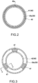
- FIG. 2 is a cross-sectional view taken along the line A-A in FIG. 1 .
- FIG. 3 is a cross-sectional view taken along the line B-B in FIG. 1 .
- FIG.4A is a cross-sectional view taken along the line C-C in FIG. 3
- FIG.4B is a cross-sectional view taken along the line C-C in FIG. 3 of a modified example.
- FIG 5A is a perspective view showing a state before joining a seam portion of a sealing mat of the exhaust purifier
- FIG 5B is a perspective view showing a state after joining the seam portion of the same sealing mat.
- the exhaust purification device 10 has a catalytic converter 20 between a metal inlet-side flange 11 located on an inlet side of exhaust gas G and a metal outlet-side flange 12 located on an outlet side of the exhaust gas G.
- the exhaust purification device 10 is a vertical type, perpendicular (upright) to a floor surface of a vehicle, with the inlet-side flange 11 placed on an upper side and the outlet-side flange 12 placed on a lower side.
- the catalytic converter 20 comprises a metal outer cylinder 30 with an upstream end portion 31 fixed by welding to an exhaust gas inlet 1 1a of the inlet-side flange 11 and a downstream end portion 32 fixed by welding to an exhaust gas outlet 12a of the outlet-side flange 12; and a metal inner cylinder 40 accommodating therein catalyst support 21 for purifying the exhaust gas G, with an upstream end portion 41 held with no gap on an upstream side of the outer cylinder 30 and a downstream end portion 42 disposed with a gap on a downstream side of the outer cylinder 30.
- the outer cylinder 30 has a cylindrical small-diameter portion 33, a conical cylindrical tapered portion 34, a large-diameter cylindrical base portion 35, a conical cylindrical tapered portion 36, and a cylindrical middle-diameter portion 37, from the upstream end portion 31 to the downstream end portion 32.
- the outer cylinder 30 accommodates the inner cylinder 40 in the large-diameter cylindrical base portion 35.
- the large-diameter cylindrical base portion 35 is fixed by welding to the conical cylindrical tapered portion 34 and 36 located on both sides. Further, a downstream end portion 36b of the conical cylindrical tapered portion 36 and an upstream end portion 37a of the cylindrical middle-diameter portion 37 are also fixed together by welding.
- the inner cylinder 40 is formed in a cylindrical shape and the upstream end portion 41 side of the inner cylinder 40 is slidably sealed by a sealing mat (heat-insulating member) 45 interposed on the entire circumference between the upstream end portion 41 side and the upstream end portion 35a side of the large-diameter cylindrical base portion 35 of the outer cylinder 30.
- the sealing mat 45 as a heat-insulating member has a surface pressure (elastic force) capable of holding the inner cylinder 40.
- the sealing mat 45 is a low thermal conductivity.
- the length of a seam portion 45a is formed to be longer than the lateral width of the sealing mat 45.
- the end surface sides facing each other of the seam portion 45a of the sealing mat 45 are formed as a crank-shape, and the length of the sealing mat 45a is formed to be longer than the lateral width of the sealing mat 45.
- the shape of the seam portion 45a of the sealing mat 45 may be formed such that the end surface sides facing each other have an uneven shape as in a seam portion 45b of the sealing mat 45 shown in FIG. 6A and FIG. 6B , or may be formed such that the end surface sides facing each other have an obliquely inclined plane shape as in a seam portion 45c of the sealing mat 45 shown in FIG. 7A and FIG. 7B .
- a downstream end portion 35b of the large-diameter cylindrical base portion 35 of the outer cylinder 30 and the downstream end portion 42 of the inner cylinder 40 are fixed together by being partially welded via a plurality of intermediate members 47, so that the exhaust gas G can pass by and flow from the downstream end portion 42 side of the inner cylinder 40 toward the upstream end portion 36a side of the conical cylindrical tapered portion 36 of the outer cylinder 30.
- an opening end 43 having a predetermined gap T is formed between the downstream end portion 42 of the inner cylinder 40 and the downstream end portion 35b of the large-diameter cylindrical base portion 35 of the outer cylinder 30.
- the exhaust gas G having flowed from the exhaust gas inlet 11a of the inlet-side flange 11 to convect from the opening end 43 of the inner cylinder 40 to the upstream side between the large-diameter cylindrical base portion 35 of the inner cylinder 40 and the outer cylinder 30 a gas layer H of the exhaust gas G is formed. Furthermore, the sum of the cross-sectional area of the predetermined gap T is set to be within 80% to 90% of the cross-sectional area between the outer cylinder 30 and the inner cylinder 40.
- the downstream end portion 42 side of the inner cylinder 40 may be fixed by being welded to a protruding portion 35c partially projecting inwardly from the downstream end portion 35b side of the large-diameter cylindrical base portion 35 of the outer cylinder 30, so that the exhaust gas G can pass by and flow from the downstream end portion 42 side of the inner cylinder 40 toward the large-diameter cylindrical base portion 35 of the outer cylinder 30.
- the catalyst support 21 for purifying the exhaust gas G is attached to the inner cylinder 40 via a holding member 22.
- the exhaust purification device 10 of the first embodiment it is possible to form a gas layer H by the exhaust gas G that flows from the opening end 43 of the inner cylinder 40 on the downstream side into between the inner cylinder 40 and the large-diameter cylindrical base portion 35 of the outer cylinder 30 which is a hollow double tube structure. Therefore, when an automobile engine is stopped, the gas layer H having a high temperature exists around the catalyst support 21 of the catalytic converter 20, so that the catalyst support 21 is kept warm.
- the catalyst of the catalyst support 21 can be activated at an early stage. Thereby, the light-off performance can be improved because the thermal mass is lowered.
- the exhaust purification device 10 is a vertical type with the inlet-side flange 11 placed on the upper side and the outlet-side flange 12 placed on the lower side, the exhaust gas G easily goes around between the large-diameter cylindrical base portion 35 and the inner cylinder 40 from the opening end 43 of the inner cylinder 40 on the downstream side.
- FIG. 8 is a cross-sectional view showing an exhaust purification device according to the second embodiment of the present invention.
- the exhaust purification device 10A of the second embodiment differs from the exhaust purification device 10 of the first embodiment in that the outside of the conical cylindrical tapered portion 34, the large-diameter cylindrical base portion 35, and the conical cylindrical tapered portion 36, of the outer cylinder 30, which are opposite to the inner cylinder 40, are covered with a heat-insulating/heat-shielding member 38.
- the heat retention of the catalyst support 21 can be further enhanced when the automobile engine is stopped.
- FIG. 9 is a cross-sectional view showing an exhaust purification device according to a third embodiment of the present invention.
- the exhaust purification device 10B of the third embodiment differs from the exhaust purification device 10 of the first embodiment in that an extended cylindrical portion 44 with a conical cylindrical distal end side and a cylindrical base side is attached to the downstream end portion 42 of the inner cylinder 40.
- the third embodiment also differs in that the downstream end portion 44b side of the extended cylindrical portion 44 is fixed to be partially welded to the downstream end portion 36b side of the conical cylindrical tapered portion 36 of the outer cylinder 30 via a plurality of intermediate members 47. Thereby, the exhaust gas G can pass by and flow from the downstream end portion 42 side of the inner cylinder 40 toward the large-diameter cylindrical base portion 35 of the outer cylinder 30.
- the same components are denoted by the same reference numerals, and detailed description thereof is omitted.
- the volume of the gas layer H by the exhaust gas G is made larger than that of the first embodiment, it is possible to further improve the heat retention of the catalyst support 21 when the engine of the automobile is stopped.
- FIG. 10 is a cross-sectional view showing an exhaust purification device according to the fourth embodiment of the present invention.
- the exhaust purification device 10C of the fourth embodiment differs from the exhaust purification device 10B of the third embodiment in that the outside of the conical cylindrical tapered portion 34, the large-diameter cylindrical base portion 35, and the conical cylindrical tapered portion 36, of the outer cylinder 30, which are opposite to the inner cylinder 40, are covered with a heat-insulating/heat-shielding member 38.
- the heat retention of the catalyst support 21 can be further enhanced when the automobile engine is stopped.
- the downstream end portion side of the inner cylinder is partially welded to the outer cylinder via the plurality of intermediate members so that the exhaust gas G can pass by and flow from the downstream end portion side of the inner cylinder toward the base portion of the outer cylinder.
- the downstream end portion side of the inner cylinder may be partially fixed to the outer cylinder via the plurality of heat-insulating members.
- the upstream end portion side of the inner cylinder is slidably sealed by a heat-insulating member interposed on the entire circumference between the upstream end portion side of the inner cylinder and the upstream end portion side of the outer cylinder
- the downstream end portion side of the inner cylinder may be slidably held by heat-insulating members interspersed between the downstream end portion side of the inner cylinder and the downstream end portion side of the outer cylinder.
- the exhaust purification device may be a horizontal type. Furthermore, it is possible to apply each of the embodiments described above, even in the type having a flange only on a side or having no flange on both sides.
Landscapes
- Engineering & Computer Science (AREA)
- Chemical & Material Sciences (AREA)
- Chemical Kinetics & Catalysis (AREA)
- Combustion & Propulsion (AREA)
- Mechanical Engineering (AREA)
- General Engineering & Computer Science (AREA)
- Health & Medical Sciences (AREA)
- Toxicology (AREA)
- Exhaust Gas After Treatment (AREA)
- Exhaust Silencers (AREA)
Description
- The present invention relates to an exhaust purification device provided in an exhaust path of an automobile.
- An exhaust purification device of this kind is disclosed, for example, in the patent document 1. The exhaust purification device disclosed in this patent document 1 is an adiabatic exhaust flow pipe which comprises an inner cylinder and an outer cylinder provided on an outer periphery of the inner cylinder, wherein the inner cylinder and the outer cylinder are circumferentially welded at each of one end portion and the other end portion, the outer peripheral surface of the inner cylinder and the inner peripheral surface of the outer cylinder are spaced to form a gap between one end portion and the other end portion, and this gap constitutes an air layer; and further, an exhaust purifying body (catalyst support) is accommodated in a cylindrical portion.
-
- Patent Document 1:
JP2016-113969A - Patent Document 2:
EP 1 464 798 A1 discloses a catalytic body fixing structure for fixing a catalytic body to an exhaust pipe serving as part of an exhaust system joined to an engine. - Patent Document 3:
JP 2001 0122239 A - Patent Document 4:
WO 2018/078955 A1 discloses an exhaust pipe containing a catalyst for purifying exhaust gas discharged from a vehicle engine and discharging the exhaust gas to a muffler. - However, in the exhaust purification device of the patent document 1, since the outer cylinder holding the inner cylinder containing the catalyst support is in contact with the outside air, the outer cylinder actively performs heat exchange and is quickly cooled. Further, when the temperature of the catalyst support decreases, the exhaust gas cannot be purified. Therefore, it is necessary to operate an engine in order to maintain the temperature of the catalyst support, and fuel efficiency and emission are worse by operating the engine.
- Accordingly, the present invention is intended to solve the problems mentioned above, and an object of the present invention is to provide an exhaust purification device that can keep the catalyst support warm.
- This invention provides an exhaust purification device having a catalytic converter into which exhaust gas flows, the catalytic converter comprising: an inner cylinder accommodating therein catalyst support for purifying the exhaust gas; and an outer cylinder having a large-diameter cylindrical base portion disposed with a predetermined gap to an outer periphery of the inner cylinder so as to surround the outer periphery of the inner cylinder, said outer cylinder having an upstream end portion serving as an inlet of the exhaust gas and a downstream end portion serving as an outlet of the exhaust gas; wherein the inner cylinder has an upstream end portion held with no gap via a heat-insulating member having an elastic force to an upstream end portion in a flow direction of the exhaust gas of the large-diameter cylindrical base portion, and has a downstream end portion disposed with the predetermined gap on a downstream side of the outer cylinder; the exhaust gas having passed through the catalyst support flows into the gap between the inner cylinder and the large-diameter cylindrical base portion through an opening end provided between a downstream side of the inner cylinder and a downstream end portion of the large-diameter cylindrical base portion in the flow direction of the exhaust gas; ; wherein a gas layer is formed by the exhaust gas having flowed into an interior of the inner cylinder from the upstream end portion of the outer cylinder, having been discharged from the downstream end portion of the inner cylinder, and convected from the predetermined gap to an upstream side between the outer cylinder and the inner cylinder.
- According to the present invention, since the exhaust gas flows from the downstream side between the outer cylinder and the inner cylinder of a hollow double tube structure to form the gas layer, the catalyst support can be kept warm. Further, the inner cylinder can be thinned. Thereby, since the thermal mass is lowered, it is possible to improve the light-off performance.
-
-
FIG. 1 is a cross-sectional view showing an exhaust purification device according to the first embodiment of the present invention. -
FIG. 2 is a cross-sectional view taken along the line A-A inFIG. 1 -
FIG. 3 is a cross-sectional view taken along the line B-B inFIG. 1 -
FIG. 4A is a cross-sectional view taken along the line C-C inFIG. 3 , andFIG. 4B is a cross-sectional view taken along the line C-C inFIG. 3 of a modified example. -
FIG. 5A is a perspective view showing a state before joining a seam portion of a sealing mat of the above-described exhaust purification device, andFIG. 5B is a perspective view showing a state after joining the seam portion of the same sealing mat. -
FIG. 6A is a perspective view showing a state before joining a seam portion of another example of the sealing mat, andFIG. 6B is a perspective view showing a state after joining the seam portion of the same sealing mat. -
FIG. 7A is a perspective view showing a state before joining a seam portion of another example of the sealing mat, andFIG. 7B is a perspective view showing a state after joining the seam portion of the same sealing mat. -
FIG. 8 is a cross-sectional view showing an exhaust purification device according to the second embodiment of the present invention. -
FIG. 9 is a cross-sectional view showing an exhaust purification device according to the third embodiment of the present invention. -
FIG. 10 is a cross-sectional view showing an exhaust purification device according to the fourth embodiment of the present invention. - Embodiments of the present invention will be described below with reference to the drawings.
-
FIG. 1 is a cross-sectional view showing an exhaust purification device according to the first embodiment of the present invention.FIG. 2 is a cross-sectional view taken along the line A-A inFIG. 1 .FIG. 3 is a cross-sectional view taken along the line B-B inFIG. 1 .FIG.4A is a cross-sectional view taken along the line C-C inFIG. 3 , andFIG.4B is a cross-sectional view taken along the line C-C inFIG. 3 of a modified example.FIG 5A is a perspective view showing a state before joining a seam portion of a sealing mat of the exhaust purifier, andFIG 5B is a perspective view showing a state after joining the seam portion of the same sealing mat. - As shown in
FIG. 1 , theexhaust purification device 10 has acatalytic converter 20 between a metal inlet-side flange 11 located on an inlet side of exhaust gas G and a metal outlet-side flange 12 located on an outlet side of the exhaust gas G. Theexhaust purification device 10 is a vertical type, perpendicular (upright) to a floor surface of a vehicle, with the inlet-side flange 11 placed on an upper side and the outlet-side flange 12 placed on a lower side. - The
catalytic converter 20 comprises a metalouter cylinder 30 with anupstream end portion 31 fixed by welding to an exhaust gas inlet 1 1a of the inlet-side flange 11 and adownstream end portion 32 fixed by welding to anexhaust gas outlet 12a of the outlet-side flange 12; and a metalinner cylinder 40 accommodating thereincatalyst support 21 for purifying the exhaust gas G, with anupstream end portion 41 held with no gap on an upstream side of theouter cylinder 30 and adownstream end portion 42 disposed with a gap on a downstream side of theouter cylinder 30. - The
outer cylinder 30 has a cylindrical small-diameter portion 33, a conical cylindricaltapered portion 34, a large-diametercylindrical base portion 35, a conical cylindricaltapered portion 36, and a cylindrical middle-diameter portion 37, from theupstream end portion 31 to thedownstream end portion 32. Theouter cylinder 30 accommodates theinner cylinder 40 in the large-diametercylindrical base portion 35. The large-diametercylindrical base portion 35 is fixed by welding to the conical cylindricaltapered portion downstream end portion 36b of the conical cylindricaltapered portion 36 and anupstream end portion 37a of the cylindrical middle-diameter portion 37 are also fixed together by welding. - As shown in
FIG. 1 andFIG. 2 , theinner cylinder 40 is formed in a cylindrical shape and theupstream end portion 41 side of theinner cylinder 40 is slidably sealed by a sealing mat (heat-insulating member) 45 interposed on the entire circumference between theupstream end portion 41 side and theupstream end portion 35a side of the large-diametercylindrical base portion 35 of theouter cylinder 30. The sealingmat 45 as a heat-insulating member has a surface pressure (elastic force) capable of holding theinner cylinder 40. The sealingmat 45 is a low thermal conductivity. Furthermore, as shown inFIG. 2 ,FIG. 5A and FIG. 5B , the length of aseam portion 45a is formed to be longer than the lateral width of the sealingmat 45. Specifically, as shown inFIG. 5A and FIG. 5B , the end surface sides facing each other of theseam portion 45a of the sealingmat 45 are formed as a crank-shape, and the length of the sealingmat 45a is formed to be longer than the lateral width of the sealingmat 45. Thus, the exhaust gas G is difficult to leak. The shape of theseam portion 45a of the sealingmat 45, not limited to a crank-shape, may be formed such that the end surface sides facing each other have an uneven shape as in aseam portion 45b of the sealingmat 45 shown inFIG. 6A and FIG. 6B , or may be formed such that the end surface sides facing each other have an obliquely inclined plane shape as in aseam portion 45c of the sealingmat 45 shown inFIG. 7A and FIG. 7B . - Further, as shown in
FIG. 1 ,FIG. 3 , andFIG. 4A , adownstream end portion 35b of the large-diametercylindrical base portion 35 of theouter cylinder 30 and thedownstream end portion 42 of theinner cylinder 40 are fixed together by being partially welded via a plurality ofintermediate members 47, so that the exhaust gas G can pass by and flow from thedownstream end portion 42 side of theinner cylinder 40 toward theupstream end portion 36a side of the conical cylindrical taperedportion 36 of theouter cylinder 30. Thus, an openingend 43 having a predetermined gap T is formed between thedownstream end portion 42 of theinner cylinder 40 and thedownstream end portion 35b of the large-diametercylindrical base portion 35 of theouter cylinder 30. Then, by allowing the exhaust gas G having flowed from theexhaust gas inlet 11a of the inlet-side flange 11 to convect from the openingend 43 of theinner cylinder 40 to the upstream side between the large-diametercylindrical base portion 35 of theinner cylinder 40 and theouter cylinder 30, a gas layer H of the exhaust gas G is formed. Furthermore, the sum of the cross-sectional area of the predetermined gap T is set to be within 80% to 90% of the cross-sectional area between theouter cylinder 30 and theinner cylinder 40. - Incidentally, as shown in
FIG. 4B , thedownstream end portion 42 side of theinner cylinder 40 may be fixed by being welded to a protrudingportion 35c partially projecting inwardly from thedownstream end portion 35b side of the large-diametercylindrical base portion 35 of theouter cylinder 30, so that the exhaust gas G can pass by and flow from thedownstream end portion 42 side of theinner cylinder 40 toward the large-diametercylindrical base portion 35 of theouter cylinder 30. Further, as shown inFIG. 1 , thecatalyst support 21 for purifying the exhaust gas G is attached to theinner cylinder 40 via a holdingmember 22. - As described above, according to the
exhaust purification device 10 of the first embodiment, it is possible to form a gas layer H by the exhaust gas G that flows from the openingend 43 of theinner cylinder 40 on the downstream side into between theinner cylinder 40 and the large-diametercylindrical base portion 35 of theouter cylinder 30 which is a hollow double tube structure. Therefore, when an automobile engine is stopped, the gas layer H having a high temperature exists around thecatalyst support 21 of thecatalytic converter 20, so that thecatalyst support 21 is kept warm. - In addition, since the thickness of the
inner cylinder 40 can be reduced, the catalyst of thecatalyst support 21 can be activated at an early stage. Thereby, the light-off performance can be improved because the thermal mass is lowered. - Furthermore, since the
exhaust purification device 10 is a vertical type with the inlet-side flange 11 placed on the upper side and the outlet-side flange 12 placed on the lower side, the exhaust gas G easily goes around between the large-diametercylindrical base portion 35 and theinner cylinder 40 from the openingend 43 of theinner cylinder 40 on the downstream side. -
FIG. 8 is a cross-sectional view showing an exhaust purification device according to the second embodiment of the present invention. - The
exhaust purification device 10A of the second embodiment differs from theexhaust purification device 10 of the first embodiment in that the outside of the conical cylindrical taperedportion 34, the large-diametercylindrical base portion 35, and the conical cylindrical taperedportion 36, of theouter cylinder 30, which are opposite to theinner cylinder 40, are covered with a heat-insulating/heat-shieldingmember 38. Incidentally, since other configurations are the same as those of the first embodiment, the same components are denoted by the same reference numerals, and detailed description thereof is omitted. - In the
exhaust purification device 10A of the second embodiment, since the outside of theouter cylinder 30, which is opposite to theinner cylinder 40, is covered with the heat-insulating/heat-shieldingmember 38, the heat retention of thecatalyst support 21 can be further enhanced when the automobile engine is stopped. -
FIG. 9 is a cross-sectional view showing an exhaust purification device according to a third embodiment of the present invention. - The
exhaust purification device 10B of the third embodiment differs from theexhaust purification device 10 of the first embodiment in that an extendedcylindrical portion 44 with a conical cylindrical distal end side and a cylindrical base side is attached to thedownstream end portion 42 of theinner cylinder 40. The third embodiment also differs in that thedownstream end portion 44b side of the extendedcylindrical portion 44 is fixed to be partially welded to thedownstream end portion 36b side of the conical cylindrical taperedportion 36 of theouter cylinder 30 via a plurality ofintermediate members 47. Thereby, the exhaust gas G can pass by and flow from thedownstream end portion 42 side of theinner cylinder 40 toward the large-diametercylindrical base portion 35 of theouter cylinder 30. Incidentally, since other configurations are the same as those of the first embodiment, the same components are denoted by the same reference numerals, and detailed description thereof is omitted. - In the
exhaust purification device 10B of the third embodiment, since the volume of the gas layer H by the exhaust gas G is made larger than that of the first embodiment, it is possible to further improve the heat retention of thecatalyst support 21 when the engine of the automobile is stopped. -
FIG. 10 is a cross-sectional view showing an exhaust purification device according to the fourth embodiment of the present invention. - The
exhaust purification device 10C of the fourth embodiment differs from theexhaust purification device 10B of the third embodiment in that the outside of the conical cylindrical taperedportion 34, the large-diametercylindrical base portion 35, and the conical cylindrical taperedportion 36, of theouter cylinder 30, which are opposite to theinner cylinder 40, are covered with a heat-insulating/heat-shieldingmember 38. Incidentally, since other configurations are the same as those of the first embodiment, the same components are denoted by the same reference numerals, and detailed description thereof is omitted. - In the
exhaust purification device 10C of the fourth embodiment, since the outside of theouter cylinder 30, which is opposite to theinner cylinder 40, is covered with a heat-insulating/heat-shieldingmember 38, the heat retention of thecatalyst support 21 can be further enhanced when the automobile engine is stopped. - Incidentally, according to the above embodiments, the downstream end portion side of the inner cylinder is partially welded to the outer cylinder via the plurality of intermediate members so that the exhaust gas G can pass by and flow from the downstream end portion side of the inner cylinder toward the base portion of the outer cylinder. However, the downstream end portion side of the inner cylinder may be partially fixed to the outer cylinder via the plurality of heat-insulating members.
- Further, according to the above embodiments, although the upstream end portion side of the inner cylinder is slidably sealed by a heat-insulating member interposed on the entire circumference between the upstream end portion side of the inner cylinder and the upstream end portion side of the outer cylinder, the downstream end portion side of the inner cylinder may be slidably held by heat-insulating members interspersed between the downstream end portion side of the inner cylinder and the downstream end portion side of the outer cylinder.
- Furthermore, according to the above embodiments, although the vertical type with an exhaust purification device between the inlet-side flange and the outlet-side flange has been described, the exhaust purification device may be a horizontal type. Furthermore, it is possible to apply each of the embodiments described above, even in the type having a flange only on a side or having no flange on both sides.
- While the contents of the present invention have been described along the embodiments, the present invention is not limited to these descriptions. Further, various modifications and improvements are possible to the extent obvious to those skilled in the art. The description and drawings that form a part of this disclosure are not limiting the present invention. Various alternative embodiments, examples, and operating techniques will be apparent to those skilled in the art from this disclosure.
- It is needless to say that the present invention includes various embodiments and the like not described herein. Therefore, the technical scope of the present invention is defined only by the matters specifying the invention regarding the following claims that are reasonable from the above description.
Claims (10)
- An exhaust purification device (10, 10A, 10B, 10C) having a catalytic converter (20) into which exhaust gas (G) flows, the catalytic converter (20) comprising:an inner cylinder (40) accommodating therein a catalyst support (21) for purifying the exhaust gas (G); andan outer cylinder (30) having a large-diameter cylindrical base portion (35) disposed with a predetermined gap (T) to an outer periphery of the inner cylinder (40) so as to surround the outer periphery of the inner cylinder (40), said outer cylinder (30) having an upstream end portion (31) serving as an inlet of the exhaust gas and a downstream end portion (32) serving as an outlet of the exhaust gas; characterized in thatthe inner cylinder (40) has an upstream end portion (41) held with no gap via a heat-insulating member (45) having an elastic force to an upstream end portion (35a) in a flow direction of the exhaust gas (G) of the large-diameter cylindrical base portion (35), and has a downstream end portion (42) disposed with the predetermined gap (T) on a downstream side of the outer cylinder (30);the exhaust gas (G) having passed through the catalyst support (21) flows into the gap (T) between the inner cylinder (40) and the large-diameter cylindrical base portion (35) through an opening end (43) provided between a downstream side of the inner cylinder (40) and a downstream end portion (35b) of the large-diameter cylindrical base portion (35) in the flow direction of the exhaust gas (G); anda gas layer is formed by the exhaust gas (G) having flowed into an interior of the inner cylinder (40) from the upstream end portion (31) of the outer cylinder, having been discharged from the downstream end portion of the inner cylinder (40), and convected from the predetermined gap (T) to an upstream side between the outer cylinder (30) and the inner cylinder (40).
- The exhaust purification device (10, 10A, 10B, 10C) according to Claim 1, whereinthe catalyst support (21) is covered by at least the gap (T) between the inner cylinder (40) and the large-diameter cylindrical base portion (35), andan upstream side of the gap (T) in the flow direction of the exhaust gas (G) is closed by the heat-insulating member (45), and a downstream side is open in the flow direction of the exhaust gas (G).
- The exhaust purification device (10, 10A, 10B, 10C) according to any one of Claims 1-2, wherein
a conical cylindrical portion with a diameter increasing toward the upstream side in the flow direction of the exhaust gas (G) is provided at the one end portion of the base portion (35)on the side where the opening end (43) is provided. - The exhaust purification device (10, 10A, 10B, 10C) according to Claim 1, wherein
the downstream end portion (42) side of the inner cylinder (40) in the flow direction of the exhaust gas (G) is partially welded to the outer cylinder (30) via a plurality of intermediate members (47). - The exhaust purification device (10, 10A, 10B, 10C) according to Claim 1, whereinthe opening end (43) of the base portion (35) in the flow direction of the exhaust gas (G) has the predetermined gap (T) to a downstream end portion (42) of the inner cylinder (40) in the flow direction of the exhaust gas (G), anda sum of a cross-sectional area of the predetermined gap (T) is within 80% to 90% of a cross-sectional area between the base portion (35) and the inner cylinder (40).
- The exhaust purification device (10, 10A, 10B, 10C) according to Claim 1, wherein
an upstream end portion (41) side of the inner cylinder (40) is slidably sealed by the heat-insulating member interposed on an entire circumference between the base portion (35) and the upstream end portion (41) side of the inner cylinder (40) in the flow direction of the exhaust gas (G). - The exhaust purification device (10, 10A, 10B, 10C) according to Claim 1, wherein
a downstream end portion (42) side of the inner cylinder (40) in the flow direction of the exhaust gas (G) is partially fixed to the downstream end portion (35b) of the large-diameter cylindrical base portion (35) of the outer cylinder (30) via a plurality of intermediate members (47). - The exhaust purification device (10, 10A, 10B, 10C) according to Claim 6, wherein
a length of a seam portion (45a, 45b, 45c) of the heat insulating member (45) is formed so as to be longer than a lateral width of the heat insulating member (45). - The exhaust purification device (10, 10A, 10B, 10C) according to any one of Claims 1-8, wherein
the base portion (35) accommodating the inner cylinder (40) is disposed vertically perpendicular to a floor surface of a vehicle. - The exhaust purification device (10, 10A, 10B, 10C) according to any one of Claims 1-9, wherein
an outside of the base portion (35) opposite the inner cylinder (40) is covered with a heat-insulating/heat-shielding member (38).
Applications Claiming Priority (2)
| Application Number | Priority Date | Filing Date | Title |
|---|---|---|---|
| JP2018095966A JP6797152B2 (en) | 2018-05-18 | 2018-05-18 | Exhaust purification device |
| PCT/JP2019/013551 WO2019220789A1 (en) | 2018-05-18 | 2019-03-28 | Exhaust purification device |
Publications (3)
| Publication Number | Publication Date |
|---|---|
| EP3795809A4 EP3795809A4 (en) | 2021-03-24 |
| EP3795809A1 EP3795809A1 (en) | 2021-03-24 |
| EP3795809B1 true EP3795809B1 (en) | 2023-11-01 |
Family
ID=68540082
Family Applications (1)
| Application Number | Title | Priority Date | Filing Date |
|---|---|---|---|
| EP19803412.6A Active EP3795809B1 (en) | 2018-05-18 | 2019-03-28 | Exhaust purification device |
Country Status (5)
| Country | Link |
|---|---|
| US (1) | US11434804B2 (en) |
| EP (1) | EP3795809B1 (en) |
| JP (1) | JP6797152B2 (en) |
| CN (1) | CN112135962B (en) |
| WO (1) | WO2019220789A1 (en) |
Families Citing this family (3)
| Publication number | Priority date | Publication date | Assignee | Title |
|---|---|---|---|---|
| JP7338524B2 (en) * | 2020-03-18 | 2023-09-05 | 日産自動車株式会社 | Exhaust Purification Catalyst Temperature Retaining Method and Exhaust Purification Catalyst Heat Retention System |
| JP7652058B2 (en) * | 2021-12-03 | 2025-03-27 | 株式会社豊田自動織機 | Exhaust pipe structure |
| DE102022107706A1 (en) * | 2022-03-31 | 2023-10-05 | Deere & Company | Exhaust system for a tractor |
Citations (1)
| Publication number | Priority date | Publication date | Assignee | Title |
|---|---|---|---|---|
| EP1464798B1 (en) * | 2003-03-31 | 2005-10-12 | HONDA MOTOR CO., Ltd. | Structure for fixing catalytic body to exhaust pipe |
Family Cites Families (28)
| Publication number | Priority date | Publication date | Assignee | Title |
|---|---|---|---|---|
| US4004888A (en) * | 1972-04-07 | 1977-01-25 | Kali-Chemie Aktiengesellschaft | Exhaust gas cleaning arrangement with a resiliently supported monolithic ceramic catalyzer |
| DE2824567A1 (en) * | 1978-06-05 | 1979-12-06 | Hoechst Ag | EXHAUST GAS CONVERTER FOR COMBUSTION ENGINES |
| JPS5768511A (en) * | 1980-10-15 | 1982-04-26 | Toyota Motor Corp | Exhaust gas purifier |
| US4416675A (en) * | 1982-02-22 | 1983-11-22 | Corning Glass Works | High capacity solid particulate filter apparatus |
| FR2588765B1 (en) * | 1985-10-17 | 1988-01-15 | Gaudfrin Guy | FILTER FOR LIQUIDS FILLED WITH SOLID PARTICLES AND FILTRATION SYSTEM COMPRISING SUCH A FILTER |
| JPH088244Y2 (en) * | 1989-06-19 | 1996-03-06 | 三菱自動車工業株式会社 | Catalytic converter |
| JPH0634927B2 (en) * | 1989-11-16 | 1994-05-11 | トヨタ自動車株式会社 | Metal carrier for exhaust gas purification catalyst |
| JPH06137142A (en) * | 1992-10-28 | 1994-05-17 | Toyota Motor Corp | Holding structure for catalyst converter |
| DE69316889T2 (en) * | 1993-08-27 | 1998-05-28 | Yamaha Motor Co Ltd | Exhaust device for an internal combustion engine |
| JP3369335B2 (en) * | 1994-11-07 | 2003-01-20 | 本田技研工業株式会社 | Exhaust gas purification device |
| JPH09108576A (en) * | 1995-10-16 | 1997-04-28 | Calsonic Corp | Metal carrier of catalyst converter |
| EP0992659B1 (en) * | 1998-10-05 | 2007-05-02 | Scambia Industrial Developments Aktiengesellschaft | Exhaust pipe element and method for producing an exhaust pipe element |
| JP2000274233A (en) * | 1999-03-23 | 2000-10-03 | Toyota Motor Corp | Catalytic converter for exhaust gas purification |
| JP4331826B2 (en) * | 1999-06-25 | 2009-09-16 | 本田技研工業株式会社 | Engine exhaust system |
| JP3680790B2 (en) * | 2001-05-02 | 2005-08-10 | 日産自動車株式会社 | Catalytic converter |
| JP2003049634A (en) * | 2001-08-03 | 2003-02-21 | Calsonic Kansei Corp | Particulate filter for vehicle |
| JP4383303B2 (en) * | 2004-09-30 | 2009-12-16 | 本田技研工業株式会社 | Exhaust gas purification device |
| JP4500643B2 (en) * | 2004-09-30 | 2010-07-14 | 東京濾器株式会社 | Black smoke purification device for diesel engine |
| JP2009167946A (en) * | 2008-01-17 | 2009-07-30 | Tokyo Roki Co Ltd | Exhaust gas purification device for diesel engine and metal gasket |
| JP5200612B2 (en) * | 2008-03-25 | 2013-06-05 | マツダ株式会社 | Vehicle powertrain arrangement structure |
| JP5146777B2 (en) * | 2009-03-11 | 2013-02-20 | 本田技研工業株式会社 | Catalyst holding structure |
| WO2011034015A1 (en) * | 2009-09-15 | 2011-03-24 | 本田技研工業株式会社 | Retention structure of honeycomb structure in exhaust gas purification device |
| US8776509B2 (en) * | 2011-03-09 | 2014-07-15 | Tenneco Automotive Operating Company Inc. | Tri-flow exhaust treatment device with reductant mixing tube |
| JP5316707B2 (en) * | 2011-03-10 | 2013-10-16 | トヨタ自動車株式会社 | Exhaust gas purification device for internal combustion engine |
| WO2013137105A1 (en) * | 2012-03-13 | 2013-09-19 | 日産自動車株式会社 | Catalytic converter |
| JP6433064B2 (en) | 2014-12-16 | 2018-12-05 | 三恵技研工業株式会社 | Exhaust purification device manufacturing method |
| BR112019008476B1 (en) * | 2016-10-27 | 2023-12-26 | Honda Motor Co., Ltd | EXHAUST PIPE |
| KR101795735B1 (en) | 2016-12-16 | 2017-11-13 | 주식회사 토리 | Hydrogen Generation Device |
-
2018
- 2018-05-18 JP JP2018095966A patent/JP6797152B2/en active Active
-
2019
- 2019-03-28 WO PCT/JP2019/013551 patent/WO2019220789A1/en not_active Ceased
- 2019-03-28 EP EP19803412.6A patent/EP3795809B1/en active Active
- 2019-03-28 CN CN201980032569.7A patent/CN112135962B/en active Active
- 2019-03-28 US US17/056,318 patent/US11434804B2/en active Active
Patent Citations (1)
| Publication number | Priority date | Publication date | Assignee | Title |
|---|---|---|---|---|
| EP1464798B1 (en) * | 2003-03-31 | 2005-10-12 | HONDA MOTOR CO., Ltd. | Structure for fixing catalytic body to exhaust pipe |
Also Published As
| Publication number | Publication date |
|---|---|
| US11434804B2 (en) | 2022-09-06 |
| JP6797152B2 (en) | 2020-12-09 |
| WO2019220789A1 (en) | 2019-11-21 |
| EP3795809A4 (en) | 2021-03-24 |
| EP3795809A1 (en) | 2021-03-24 |
| JP2019199851A (en) | 2019-11-21 |
| CN112135962B (en) | 2022-08-05 |
| CN112135962A (en) | 2020-12-25 |
| US20210254531A1 (en) | 2021-08-19 |
Similar Documents
| Publication | Publication Date | Title |
|---|---|---|
| US9003780B2 (en) | Exhaust gas purification device | |
| US4239733A (en) | Catalytic converter having a monolith with support and seal means therefor | |
| US8721977B2 (en) | Exhaust treatment device with integral mount | |
| US11434804B2 (en) | Exhaust purification device | |
| WO2017078088A1 (en) | Turbine housing | |
| CN105422234B (en) | Exhaust apparatus | |
| JP6789405B2 (en) | Pipe clamps and pipe fittings with sensor housing | |
| US6962346B2 (en) | Gasket and heat shield assembly for a flanged joint | |
| JP2016217337A (en) | Gasket for reductant injector and exhaust gas aftertreatment device including the same | |
| JP2952997B2 (en) | Exhaust gas purification device | |
| WO2013099872A1 (en) | Exhaust processing device | |
| US20170321592A1 (en) | Compact Inline Inlet With Integrated Cast Ring | |
| US8997922B1 (en) | Exhaust muffler for vehicle | |
| JP2016056788A (en) | Exhaust pipe with catalyst installed in the vehicle | |
| US7517501B2 (en) | Exhaust system for internal combustion engines | |
| US20040170540A1 (en) | Internally shielded catalytic converter | |
| JP2009052441A (en) | Exhaust purification device | |
| JP2020153272A (en) | Catalyst converter | |
| JP2962438B2 (en) | Exhaust manifold | |
| US8985272B1 (en) | Exhaust muffler for vehicle | |
| JP2016109106A (en) | Exhaust emission control system | |
| EP1911943B1 (en) | Exhaust gas cooling device | |
| JP6167684B2 (en) | Chemical heat storage device | |
| JP7138784B2 (en) | Catalytic device | |
| JP2005171823A (en) | Catalyst carrier, catalyst device, and engine exhaust device |
Legal Events
| Date | Code | Title | Description |
|---|---|---|---|
| STAA | Information on the status of an ep patent application or granted ep patent |
Free format text: STATUS: THE INTERNATIONAL PUBLICATION HAS BEEN MADE |
|
| PUAI | Public reference made under article 153(3) epc to a published international application that has entered the european phase |
Free format text: ORIGINAL CODE: 0009012 |
|
| STAA | Information on the status of an ep patent application or granted ep patent |
Free format text: STATUS: REQUEST FOR EXAMINATION WAS MADE |
|
| 17P | Request for examination filed |
Effective date: 20201211 |
|
| A4 | Supplementary search report drawn up and despatched |
Effective date: 20210218 |
|
| AK | Designated contracting states |
Kind code of ref document: A1 Designated state(s): AL AT BE BG CH CY CZ DE DK EE ES FI FR GB GR HR HU IE IS IT LI LT LU LV MC MK MT NL NO PL PT RO RS SE SI SK SM TR |
|
| AX | Request for extension of the european patent |
Extension state: BA ME |
|
| DAV | Request for validation of the european patent (deleted) | ||
| DAX | Request for extension of the european patent (deleted) | ||
| STAA | Information on the status of an ep patent application or granted ep patent |
Free format text: STATUS: EXAMINATION IS IN PROGRESS |
|
| 17Q | First examination report despatched |
Effective date: 20211115 |
|
| GRAP | Despatch of communication of intention to grant a patent |
Free format text: ORIGINAL CODE: EPIDOSNIGR1 |
|
| STAA | Information on the status of an ep patent application or granted ep patent |
Free format text: STATUS: GRANT OF PATENT IS INTENDED |
|
| INTG | Intention to grant announced |
Effective date: 20230613 |
|
| P01 | Opt-out of the competence of the unified patent court (upc) registered |
Effective date: 20230803 |
|
| GRAS | Grant fee paid |
Free format text: ORIGINAL CODE: EPIDOSNIGR3 |
|
| GRAA | (expected) grant |
Free format text: ORIGINAL CODE: 0009210 |
|
| STAA | Information on the status of an ep patent application or granted ep patent |
Free format text: STATUS: THE PATENT HAS BEEN GRANTED |
|
| AK | Designated contracting states |
Kind code of ref document: B1 Designated state(s): AL AT BE BG CH CY CZ DE DK EE ES FI FR GB GR HR HU IE IS IT LI LT LU LV MC MK MT NL NO PL PT RO RS SE SI SK SM TR |
|
| REG | Reference to a national code |
Ref country code: GB Ref legal event code: FG4D |
|
| REG | Reference to a national code |
Ref country code: CH Ref legal event code: EP |
|
| REG | Reference to a national code |
Ref country code: IE Ref legal event code: FG4D |
|
| REG | Reference to a national code |
Ref country code: DE Ref legal event code: R096 Ref document number: 602019040687 Country of ref document: DE |
|
| REG | Reference to a national code |
Ref country code: LT Ref legal event code: MG9D |
|
| REG | Reference to a national code |
Ref country code: NL Ref legal event code: MP Effective date: 20231101 |
|
| PG25 | Lapsed in a contracting state [announced via postgrant information from national office to epo] |
Ref country code: GR Free format text: LAPSE BECAUSE OF FAILURE TO SUBMIT A TRANSLATION OF THE DESCRIPTION OR TO PAY THE FEE WITHIN THE PRESCRIBED TIME-LIMIT Effective date: 20240202 |
|
| PG25 | Lapsed in a contracting state [announced via postgrant information from national office to epo] |
Ref country code: IS Free format text: LAPSE BECAUSE OF FAILURE TO SUBMIT A TRANSLATION OF THE DESCRIPTION OR TO PAY THE FEE WITHIN THE PRESCRIBED TIME-LIMIT Effective date: 20240301 |
|
| PG25 | Lapsed in a contracting state [announced via postgrant information from national office to epo] |
Ref country code: LT Free format text: LAPSE BECAUSE OF FAILURE TO SUBMIT A TRANSLATION OF THE DESCRIPTION OR TO PAY THE FEE WITHIN THE PRESCRIBED TIME-LIMIT Effective date: 20231101 |
|
| REG | Reference to a national code |
Ref country code: AT Ref legal event code: MK05 Ref document number: 1627447 Country of ref document: AT Kind code of ref document: T Effective date: 20231101 |
|
| PG25 | Lapsed in a contracting state [announced via postgrant information from national office to epo] |
Ref country code: NL Free format text: LAPSE BECAUSE OF FAILURE TO SUBMIT A TRANSLATION OF THE DESCRIPTION OR TO PAY THE FEE WITHIN THE PRESCRIBED TIME-LIMIT Effective date: 20231101 |
|
| PG25 | Lapsed in a contracting state [announced via postgrant information from national office to epo] |
Ref country code: AT Free format text: LAPSE BECAUSE OF FAILURE TO SUBMIT A TRANSLATION OF THE DESCRIPTION OR TO PAY THE FEE WITHIN THE PRESCRIBED TIME-LIMIT Effective date: 20231101 |
|
| PG25 | Lapsed in a contracting state [announced via postgrant information from national office to epo] |
Ref country code: ES Free format text: LAPSE BECAUSE OF FAILURE TO SUBMIT A TRANSLATION OF THE DESCRIPTION OR TO PAY THE FEE WITHIN THE PRESCRIBED TIME-LIMIT Effective date: 20231101 |
|
| PG25 | Lapsed in a contracting state [announced via postgrant information from national office to epo] |
Ref country code: NL Free format text: LAPSE BECAUSE OF FAILURE TO SUBMIT A TRANSLATION OF THE DESCRIPTION OR TO PAY THE FEE WITHIN THE PRESCRIBED TIME-LIMIT Effective date: 20231101 Ref country code: LT Free format text: LAPSE BECAUSE OF FAILURE TO SUBMIT A TRANSLATION OF THE DESCRIPTION OR TO PAY THE FEE WITHIN THE PRESCRIBED TIME-LIMIT Effective date: 20231101 Ref country code: IS Free format text: LAPSE BECAUSE OF FAILURE TO SUBMIT A TRANSLATION OF THE DESCRIPTION OR TO PAY THE FEE WITHIN THE PRESCRIBED TIME-LIMIT Effective date: 20240301 Ref country code: GR Free format text: LAPSE BECAUSE OF FAILURE TO SUBMIT A TRANSLATION OF THE DESCRIPTION OR TO PAY THE FEE WITHIN THE PRESCRIBED TIME-LIMIT Effective date: 20240202 Ref country code: ES Free format text: LAPSE BECAUSE OF FAILURE TO SUBMIT A TRANSLATION OF THE DESCRIPTION OR TO PAY THE FEE WITHIN THE PRESCRIBED TIME-LIMIT Effective date: 20231101 Ref country code: BG Free format text: LAPSE BECAUSE OF FAILURE TO SUBMIT A TRANSLATION OF THE DESCRIPTION OR TO PAY THE FEE WITHIN THE PRESCRIBED TIME-LIMIT Effective date: 20240201 Ref country code: AT Free format text: LAPSE BECAUSE OF FAILURE TO SUBMIT A TRANSLATION OF THE DESCRIPTION OR TO PAY THE FEE WITHIN THE PRESCRIBED TIME-LIMIT Effective date: 20231101 Ref country code: PT Free format text: LAPSE BECAUSE OF FAILURE TO SUBMIT A TRANSLATION OF THE DESCRIPTION OR TO PAY THE FEE WITHIN THE PRESCRIBED TIME-LIMIT Effective date: 20240301 |
|
| PG25 | Lapsed in a contracting state [announced via postgrant information from national office to epo] |
Ref country code: SE Free format text: LAPSE BECAUSE OF FAILURE TO SUBMIT A TRANSLATION OF THE DESCRIPTION OR TO PAY THE FEE WITHIN THE PRESCRIBED TIME-LIMIT Effective date: 20231101 Ref country code: RS Free format text: LAPSE BECAUSE OF FAILURE TO SUBMIT A TRANSLATION OF THE DESCRIPTION OR TO PAY THE FEE WITHIN THE PRESCRIBED TIME-LIMIT Effective date: 20231101 Ref country code: PL Free format text: LAPSE BECAUSE OF FAILURE TO SUBMIT A TRANSLATION OF THE DESCRIPTION OR TO PAY THE FEE WITHIN THE PRESCRIBED TIME-LIMIT Effective date: 20231101 Ref country code: NO Free format text: LAPSE BECAUSE OF FAILURE TO SUBMIT A TRANSLATION OF THE DESCRIPTION OR TO PAY THE FEE WITHIN THE PRESCRIBED TIME-LIMIT Effective date: 20240201 Ref country code: LV Free format text: LAPSE BECAUSE OF FAILURE TO SUBMIT A TRANSLATION OF THE DESCRIPTION OR TO PAY THE FEE WITHIN THE PRESCRIBED TIME-LIMIT Effective date: 20231101 Ref country code: HR Free format text: LAPSE BECAUSE OF FAILURE TO SUBMIT A TRANSLATION OF THE DESCRIPTION OR TO PAY THE FEE WITHIN THE PRESCRIBED TIME-LIMIT Effective date: 20231101 |
|
| PG25 | Lapsed in a contracting state [announced via postgrant information from national office to epo] |
Ref country code: DK Free format text: LAPSE BECAUSE OF FAILURE TO SUBMIT A TRANSLATION OF THE DESCRIPTION OR TO PAY THE FEE WITHIN THE PRESCRIBED TIME-LIMIT Effective date: 20231101 |
|
| PG25 | Lapsed in a contracting state [announced via postgrant information from national office to epo] |
Ref country code: CZ Free format text: LAPSE BECAUSE OF FAILURE TO SUBMIT A TRANSLATION OF THE DESCRIPTION OR TO PAY THE FEE WITHIN THE PRESCRIBED TIME-LIMIT Effective date: 20231101 |
|
| PG25 | Lapsed in a contracting state [announced via postgrant information from national office to epo] |
Ref country code: SK Free format text: LAPSE BECAUSE OF FAILURE TO SUBMIT A TRANSLATION OF THE DESCRIPTION OR TO PAY THE FEE WITHIN THE PRESCRIBED TIME-LIMIT Effective date: 20231101 |
|
| PG25 | Lapsed in a contracting state [announced via postgrant information from national office to epo] |
Ref country code: SM Free format text: LAPSE BECAUSE OF FAILURE TO SUBMIT A TRANSLATION OF THE DESCRIPTION OR TO PAY THE FEE WITHIN THE PRESCRIBED TIME-LIMIT Effective date: 20231101 Ref country code: SK Free format text: LAPSE BECAUSE OF FAILURE TO SUBMIT A TRANSLATION OF THE DESCRIPTION OR TO PAY THE FEE WITHIN THE PRESCRIBED TIME-LIMIT Effective date: 20231101 Ref country code: IT Free format text: LAPSE BECAUSE OF FAILURE TO SUBMIT A TRANSLATION OF THE DESCRIPTION OR TO PAY THE FEE WITHIN THE PRESCRIBED TIME-LIMIT Effective date: 20231101 Ref country code: EE Free format text: LAPSE BECAUSE OF FAILURE TO SUBMIT A TRANSLATION OF THE DESCRIPTION OR TO PAY THE FEE WITHIN THE PRESCRIBED TIME-LIMIT Effective date: 20231101 Ref country code: DK Free format text: LAPSE BECAUSE OF FAILURE TO SUBMIT A TRANSLATION OF THE DESCRIPTION OR TO PAY THE FEE WITHIN THE PRESCRIBED TIME-LIMIT Effective date: 20231101 Ref country code: CZ Free format text: LAPSE BECAUSE OF FAILURE TO SUBMIT A TRANSLATION OF THE DESCRIPTION OR TO PAY THE FEE WITHIN THE PRESCRIBED TIME-LIMIT Effective date: 20231101 |
|
| REG | Reference to a national code |
Ref country code: DE Ref legal event code: R097 Ref document number: 602019040687 Country of ref document: DE |
|
| PLBE | No opposition filed within time limit |
Free format text: ORIGINAL CODE: 0009261 |
|
| STAA | Information on the status of an ep patent application or granted ep patent |
Free format text: STATUS: NO OPPOSITION FILED WITHIN TIME LIMIT |
|
| 26N | No opposition filed |
Effective date: 20240802 |
|
| PG25 | Lapsed in a contracting state [announced via postgrant information from national office to epo] |
Ref country code: SI Free format text: LAPSE BECAUSE OF FAILURE TO SUBMIT A TRANSLATION OF THE DESCRIPTION OR TO PAY THE FEE WITHIN THE PRESCRIBED TIME-LIMIT Effective date: 20231101 |
|
| PG25 | Lapsed in a contracting state [announced via postgrant information from national office to epo] |
Ref country code: SI Free format text: LAPSE BECAUSE OF FAILURE TO SUBMIT A TRANSLATION OF THE DESCRIPTION OR TO PAY THE FEE WITHIN THE PRESCRIBED TIME-LIMIT Effective date: 20231101 |
|
| REG | Reference to a national code |
Ref country code: CH Ref legal event code: PL |
|
| PG25 | Lapsed in a contracting state [announced via postgrant information from national office to epo] |
Ref country code: LU Free format text: LAPSE BECAUSE OF NON-PAYMENT OF DUE FEES Effective date: 20240328 |
|
| PG25 | Lapsed in a contracting state [announced via postgrant information from national office to epo] |
Ref country code: MC Free format text: LAPSE BECAUSE OF FAILURE TO SUBMIT A TRANSLATION OF THE DESCRIPTION OR TO PAY THE FEE WITHIN THE PRESCRIBED TIME-LIMIT Effective date: 20231101 |
|
| GBPC | Gb: european patent ceased through non-payment of renewal fee |
Effective date: 20240328 |
|
| PG25 | Lapsed in a contracting state [announced via postgrant information from national office to epo] |
Ref country code: MC Free format text: LAPSE BECAUSE OF FAILURE TO SUBMIT A TRANSLATION OF THE DESCRIPTION OR TO PAY THE FEE WITHIN THE PRESCRIBED TIME-LIMIT Effective date: 20231101 Ref country code: LU Free format text: LAPSE BECAUSE OF NON-PAYMENT OF DUE FEES Effective date: 20240328 |
|
| REG | Reference to a national code |
Ref country code: BE Ref legal event code: MM Effective date: 20240331 |
|
| PG25 | Lapsed in a contracting state [announced via postgrant information from national office to epo] |
Ref country code: BE Free format text: LAPSE BECAUSE OF NON-PAYMENT OF DUE FEES Effective date: 20240331 |
|
| PG25 | Lapsed in a contracting state [announced via postgrant information from national office to epo] |
Ref country code: GB Free format text: LAPSE BECAUSE OF NON-PAYMENT OF DUE FEES Effective date: 20240328 |
|
| PG25 | Lapsed in a contracting state [announced via postgrant information from national office to epo] |
Ref country code: IE Free format text: LAPSE BECAUSE OF NON-PAYMENT OF DUE FEES Effective date: 20240328 |
|
| PG25 | Lapsed in a contracting state [announced via postgrant information from national office to epo] |
Ref country code: IE Free format text: LAPSE BECAUSE OF NON-PAYMENT OF DUE FEES Effective date: 20240328 Ref country code: GB Free format text: LAPSE BECAUSE OF NON-PAYMENT OF DUE FEES Effective date: 20240328 Ref country code: BE Free format text: LAPSE BECAUSE OF NON-PAYMENT OF DUE FEES Effective date: 20240331 Ref country code: CH Free format text: LAPSE BECAUSE OF NON-PAYMENT OF DUE FEES Effective date: 20240331 |
|
| PG25 | Lapsed in a contracting state [announced via postgrant information from national office to epo] |
Ref country code: RO Free format text: LAPSE BECAUSE OF FAILURE TO SUBMIT A TRANSLATION OF THE DESCRIPTION OR TO PAY THE FEE WITHIN THE PRESCRIBED TIME-LIMIT Effective date: 20231101 |
|
| PG25 | Lapsed in a contracting state [announced via postgrant information from national office to epo] |
Ref country code: CY Free format text: LAPSE BECAUSE OF FAILURE TO SUBMIT A TRANSLATION OF THE DESCRIPTION OR TO PAY THE FEE WITHIN THE PRESCRIBED TIME-LIMIT; INVALID AB INITIO Effective date: 20190328 |
|
| PG25 | Lapsed in a contracting state [announced via postgrant information from national office to epo] |
Ref country code: HU Free format text: LAPSE BECAUSE OF FAILURE TO SUBMIT A TRANSLATION OF THE DESCRIPTION OR TO PAY THE FEE WITHIN THE PRESCRIBED TIME-LIMIT; INVALID AB INITIO Effective date: 20190328 |
|
| PG25 | Lapsed in a contracting state [announced via postgrant information from national office to epo] |
Ref country code: FI Free format text: LAPSE BECAUSE OF FAILURE TO SUBMIT A TRANSLATION OF THE DESCRIPTION OR TO PAY THE FEE WITHIN THE PRESCRIBED TIME-LIMIT Effective date: 20231101 |
|
| PG25 | Lapsed in a contracting state [announced via postgrant information from national office to epo] |
Ref country code: TR Free format text: LAPSE BECAUSE OF FAILURE TO SUBMIT A TRANSLATION OF THE DESCRIPTION OR TO PAY THE FEE WITHIN THE PRESCRIBED TIME-LIMIT Effective date: 20231101 |
|
| PGFP | Annual fee paid to national office [announced via postgrant information from national office to epo] |
Ref country code: DE Payment date: 20260219 Year of fee payment: 8 |
|
| PGFP | Annual fee paid to national office [announced via postgrant information from national office to epo] |
Ref country code: FR Payment date: 20260219 Year of fee payment: 8 |