EP3795801A1 - Unitized rotor assembly - Google Patents
Unitized rotor assembly Download PDFInfo
- Publication number
- EP3795801A1 EP3795801A1 EP20197018.3A EP20197018A EP3795801A1 EP 3795801 A1 EP3795801 A1 EP 3795801A1 EP 20197018 A EP20197018 A EP 20197018A EP 3795801 A1 EP3795801 A1 EP 3795801A1
- Authority
- EP
- European Patent Office
- Prior art keywords
- rotor assembly
- turbine
- compressor
- structural member
- inconel
- Prior art date
- Legal status (The legal status is an assumption and is not a legal conclusion. Google has not performed a legal analysis and makes no representation as to the accuracy of the status listed.)
- Pending
Links
Images
Classifications
-
- F—MECHANICAL ENGINEERING; LIGHTING; HEATING; WEAPONS; BLASTING
- F01—MACHINES OR ENGINES IN GENERAL; ENGINE PLANTS IN GENERAL; STEAM ENGINES
- F01D—NON-POSITIVE DISPLACEMENT MACHINES OR ENGINES, e.g. STEAM TURBINES
- F01D5/00—Blades; Blade-carrying members; Heating, heat-insulating, cooling or antivibration means on the blades or the members
- F01D5/34—Rotor-blade aggregates of unitary construction, e.g. formed of sheet laminae
-
- F—MECHANICAL ENGINEERING; LIGHTING; HEATING; WEAPONS; BLASTING
- F01—MACHINES OR ENGINES IN GENERAL; ENGINE PLANTS IN GENERAL; STEAM ENGINES
- F01D—NON-POSITIVE DISPLACEMENT MACHINES OR ENGINES, e.g. STEAM TURBINES
- F01D5/00—Blades; Blade-carrying members; Heating, heat-insulating, cooling or antivibration means on the blades or the members
- F01D5/02—Blade-carrying members, e.g. rotors
- F01D5/04—Blade-carrying members, e.g. rotors for radial-flow machines or engines
- F01D5/043—Blade-carrying members, e.g. rotors for radial-flow machines or engines of the axial inlet- radial outlet, or vice versa, type
- F01D5/048—Form or construction
-
- B—PERFORMING OPERATIONS; TRANSPORTING
- B22—CASTING; POWDER METALLURGY
- B22F—WORKING METALLIC POWDER; MANUFACTURE OF ARTICLES FROM METALLIC POWDER; MAKING METALLIC POWDER; APPARATUS OR DEVICES SPECIALLY ADAPTED FOR METALLIC POWDER
- B22F3/00—Manufacture of workpieces or articles from metallic powder characterised by the manner of compacting or sintering; Apparatus specially adapted therefor ; Presses and furnaces
- B22F3/12—Both compacting and sintering
- B22F3/14—Both compacting and sintering simultaneously
- B22F3/15—Hot isostatic pressing
-
- B—PERFORMING OPERATIONS; TRANSPORTING
- B22—CASTING; POWDER METALLURGY
- B22F—WORKING METALLIC POWDER; MANUFACTURE OF ARTICLES FROM METALLIC POWDER; MAKING METALLIC POWDER; APPARATUS OR DEVICES SPECIALLY ADAPTED FOR METALLIC POWDER
- B22F5/00—Manufacture of workpieces or articles from metallic powder characterised by the special shape of the product
- B22F5/04—Manufacture of workpieces or articles from metallic powder characterised by the special shape of the product of turbine blades
-
- F—MECHANICAL ENGINEERING; LIGHTING; HEATING; WEAPONS; BLASTING
- F02—COMBUSTION ENGINES; HOT-GAS OR COMBUSTION-PRODUCT ENGINE PLANTS
- F02C—GAS-TURBINE PLANTS; AIR INTAKES FOR JET-PROPULSION PLANTS; CONTROLLING FUEL SUPPLY IN AIR-BREATHING JET-PROPULSION PLANTS
- F02C3/00—Gas-turbine plants characterised by the use of combustion products as the working fluid
- F02C3/04—Gas-turbine plants characterised by the use of combustion products as the working fluid having a turbine driving a compressor
- F02C3/045—Gas-turbine plants characterised by the use of combustion products as the working fluid having a turbine driving a compressor having compressor and turbine passages in a single rotor-module
- F02C3/05—Gas-turbine plants characterised by the use of combustion products as the working fluid having a turbine driving a compressor having compressor and turbine passages in a single rotor-module the compressor and the turbine being of the radial flow type
-
- B—PERFORMING OPERATIONS; TRANSPORTING
- B22—CASTING; POWDER METALLURGY
- B22F—WORKING METALLIC POWDER; MANUFACTURE OF ARTICLES FROM METALLIC POWDER; MAKING METALLIC POWDER; APPARATUS OR DEVICES SPECIALLY ADAPTED FOR METALLIC POWDER
- B22F2301/00—Metallic composition of the powder or its coating
- B22F2301/15—Nickel or cobalt
-
- B—PERFORMING OPERATIONS; TRANSPORTING
- B33—ADDITIVE MANUFACTURING TECHNOLOGY
- B33Y—ADDITIVE MANUFACTURING, i.e. MANUFACTURING OF THREE-DIMENSIONAL [3D] OBJECTS BY ADDITIVE DEPOSITION, ADDITIVE AGGLOMERATION OR ADDITIVE LAYERING, e.g. BY 3D PRINTING, STEREOLITHOGRAPHY OR SELECTIVE LASER SINTERING
- B33Y10/00—Processes of additive manufacturing
-
- B—PERFORMING OPERATIONS; TRANSPORTING
- B33—ADDITIVE MANUFACTURING TECHNOLOGY
- B33Y—ADDITIVE MANUFACTURING, i.e. MANUFACTURING OF THREE-DIMENSIONAL [3D] OBJECTS BY ADDITIVE DEPOSITION, ADDITIVE AGGLOMERATION OR ADDITIVE LAYERING, e.g. BY 3D PRINTING, STEREOLITHOGRAPHY OR SELECTIVE LASER SINTERING
- B33Y80/00—Products made by additive manufacturing
-
- F—MECHANICAL ENGINEERING; LIGHTING; HEATING; WEAPONS; BLASTING
- F05—INDEXING SCHEMES RELATING TO ENGINES OR PUMPS IN VARIOUS SUBCLASSES OF CLASSES F01-F04
- F05D—INDEXING SCHEME FOR ASPECTS RELATING TO NON-POSITIVE-DISPLACEMENT MACHINES OR ENGINES, GAS-TURBINES OR JET-PROPULSION PLANTS
- F05D2230/00—Manufacture
- F05D2230/30—Manufacture with deposition of material
- F05D2230/31—Layer deposition
-
- F—MECHANICAL ENGINEERING; LIGHTING; HEATING; WEAPONS; BLASTING
- F05—INDEXING SCHEMES RELATING TO ENGINES OR PUMPS IN VARIOUS SUBCLASSES OF CLASSES F01-F04
- F05D—INDEXING SCHEME FOR ASPECTS RELATING TO NON-POSITIVE-DISPLACEMENT MACHINES OR ENGINES, GAS-TURBINES OR JET-PROPULSION PLANTS
- F05D2300/00—Materials; Properties thereof
- F05D2300/10—Metals, alloys or intermetallic compounds
- F05D2300/17—Alloys
- F05D2300/175—Superalloys
-
- Y—GENERAL TAGGING OF NEW TECHNOLOGICAL DEVELOPMENTS; GENERAL TAGGING OF CROSS-SECTIONAL TECHNOLOGIES SPANNING OVER SEVERAL SECTIONS OF THE IPC; TECHNICAL SUBJECTS COVERED BY FORMER USPC CROSS-REFERENCE ART COLLECTIONS [XRACs] AND DIGESTS
- Y02—TECHNOLOGIES OR APPLICATIONS FOR MITIGATION OR ADAPTATION AGAINST CLIMATE CHANGE
- Y02T—CLIMATE CHANGE MITIGATION TECHNOLOGIES RELATED TO TRANSPORTATION
- Y02T50/00—Aeronautics or air transport
- Y02T50/60—Efficient propulsion technologies, e.g. for aircraft
Definitions
- the present disclosure relates generally to rotor assemblies.
- the present disclosure relates to additively manufactured rotor assemblies.
- Turbojets use turbomachinery to generate thrust to propel an air vehicle.
- Turbojets utilize a rotor assembly typically including a compressor, a shaft, and a turbine.
- the compressor ingests ambient air and compresses the air to be diffused and then directed to the combustor for mixing of the compressed air and fuel for ignition and combustion.
- the resulting hot gas is then directed to the turbine to create power and thrust.
- Manufacturing of the turbojet rotor assembly often includes procuring raw material for the three major components in the form of raw stock, forgings, or castings. The procured raw material for each component is then separately heat treated, and machined to final detailed dimensions. Each component is separately inspected and balanced individually. Lastly, the components are brought together and assembled, and balanced again as a rotor assembly. In some instances, the rotor assembly can be pre-spun to verify the integrity of any cast components due to susceptibility to sub-surface defects.
- a method of making a rotor assembly of a turbojet includes building the rotor assembly via layer-by-layer additive manufacturing.
- a turbine portion is formed and a compressor portion is integrally formed with the turbine portion.
- a shaft portion is integrally formed with the compressor portion.
- a material of the rotor assembly includes a nickel based alloy.
- a rotor assembly of a turbojet includes a turbine portion, a compressor portion, and a shaft portion.
- the compressor portion integrally formed with the turbine portion.
- the shaft portion is integrally formed with the compressor portion.
- a materials of the rotor assembly comprises a nickel based alloy.
- This disclosure presents an additively manufactured rotor assembly that results from integrating a compressor, turbine, and shaft into a single additively manufactured part requiring a minimum of material, heat treatment, machining, assembly, and balancing to complete the part.
- the additively manufactured rotor assembly by virtue of eliminating the cast turbine wheel, will eliminate premature in-service failures from subsurface casting defects of the turbine wheel.
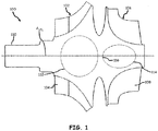
- FIG. 1 is a cross-section view of first rotor assembly 100 and shows first compressor portion 102 (with first compressor blades 104), first turbine portion 106 (with first turbine blades 108), first shaft portion 110, first cavity 112, second cavity 114, first structural member 116, and first centerline axis A 1CL .
- First rotor assembly 100 is a single additively manufactured part including first compressor portion 102, first turbine portion 106, and first shaft portion 110.
- first rotor assembly 100 is made from a laser beam melting or electron beam melting layer-by-layer additive manufacturing process.
- First rotor assembly 100 can be formed, at least in part, of a nickel based alloy capable of high strength at high operating temperatures (e.g., an age hardening austenitic (face-centred cubic) nickel-based superalloy) such as Inconel 718, Waspaloy, Haynes 282, Inconel 713, Inconel 738, Mar M 247, or Inconel 792.
- a nickel based alloy capable of high strength at high operating temperatures
- an age hardening austenitic (face-centred cubic) nickel-based superalloy such as Inconel 718, Waspaloy, Haynes 282, Inconel 713, Inconel 738, Mar M 247, or Inconel 792.
- First compressor portion 102 is a compressor rotor.
- first compressor portion 102 is a radial compressor.
- First compressor blades 104 and first turbine blades 108 are airfoil blades.
- First turbine portion 106 is a turbine rotor. In this non-limiting embodiment, first turbine portion 106 is a radial turbine.
- First shaft portion 110 is a cylinder (with or without a hollow portion) of solid material.
- First cavity 112 and second cavity 114 are pockets or voids. In this example, first cavity 112 is approximately spherical and second cavity is approximately ellipsoidal.
- First structural member 116 is a piece or section of solid material disposed substantially in a plane transverse (e.g., orthogonal) to first centerline axis A 1CL and situated between first cavity 112 and second cavity 114.
- First centerline axis A 1CL is an imaginary axis about which first rotor assembly 100 rotates.
- First and second cavities 112 and 114 can be inter-connected to evacuate entrapped powder particles through another channel running through a hub of first compressor portion 102 or first turbine portion 106.
- first rotor assembly 100 is part of a turbojet engine for an aircraft.
- first rotor assembly 100 is built via layer-by-layer additive manufacturing such that first compressor portion 102, first turbine portion 106, and first shaft portion 110 are integrally formed as a single, unitized piece of material.
- First compressor portion 102 is integrally formed with and connected to first turbine portion 106.
- First compressor blades 104 are disposed radially outward from first centerline axis A 1CL along an outer radial perimeter of first compressor portion 102.
- First turbine portion 106 is integrally formed with and connected to both first compressor portion 102 and to first shaft portion 110.
- First turbine blades 108 are disposed radially outward from first centerline axis A 1CL along an outer radial perimeter of first turbine portion 106.
- First shaft portion 110 is integrally formed with and connected to first compressor portion 102.
- first cavity 112 is disposed inside of first compressor portion 102 and second cavity 114 is disposed inside of first turbine portion 106.
- First structural member 116 is disposed between first compressor portion 102 and first turbine portion 106.
- first compressor portion 102, first turbine portion 106, first shaft portion 110, first cavity 112, and second cavity 114 are disposed coaxially about first centerline axis A 1CL .
- first compressor portion 102 ingests ambient air and compresses the air to be diffused and then directed to a combustor for mixing of the compressed air and fuel for ignition and combustion. The resulting hot gas is then directed to first turbine portion 106 to create power and thrust for the aircraft turbojet engine.
- First shaft portion 110 transfers torque to and from first rotor assembly 100 between other components of the aircraft turbojet engine.
- First cavity 112 and second cavity 114 provide for a reduction in mass and weight for first rotor assembly 100.
- First structural member 116 provides structural support to both first compressor portion 102 and to first turbine portion 106.
- first structural member 116 includes an average section stress less than a yield tensile strength of the material of first rotor assembly 100 at a maximum operating temperature.
- first rotor assembly 100 Utilizing additive manufacturing to build first rotor assembly 100 instead of casting processes, eliminates premature in-service failures from turbine wheel subsurface casting defects that can occur with casting processes.
- the single material selected for the additive manufacturing of first rotor assembly 100 meets the strength and stiffness requirements of each of first compressor portion 102, first turbine portion 106, and first shaft portion 110.
- the nickel based alloy material of first rotor assembly 100 is strong enough to support first turbine portion 106, which typically experiences the greatest strain and highest temperatures as compared to first compressor portion 102 and first shaft portion 110.
- the creep rupture properties (ability to maintain high strength at high temperature) of the nickel based alloy material of first rotor assembly 100 extends the life of first rotor at service temperature and, hence, maximizes the operating turbine inlet temperature and therefore the specific power density required by first rotor assembly 100.
- the nickel based alloy material selected shall be conducive to additive manufacturing in regards to weldability, defect minimization, and dimensional stability and precision.
- a heat treatment can be applied to first rotor assembly 100.
- a hot isostatic press process can be applied to first rotor assembly 100.
- an abrasive flow machining process can be applied to first rotor assembly 100 in order to smooth a portion of a surface of first rotor assembly 100.
- First rotor assembly 100 also costs less to manufacture than a non-additively manufactured rotor assembly due to additive manufacturing technology that reduces material processing, machining, scrap rate, and assembly compared to a typical multipart rotor assembly.
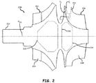
- FIG. 2 is a cross-section view of second rotor assembly 200 and shows second compressor portion 202 (with second compressor blades 204), second turbine portion 206 (with second turbine blades 208), second shaft portion 210, first cavity 212, second cavity 214, second structural member 216, slot 218, first channel C 1 , second channel C 2 , third channel C 3 , and second centerline axis A 2CL .
- second rotor assembly 200 generally parallels first rotor assembly 100, discussed above.
- second rotor assembly 200 and its components second rotor assembly 200 operates in the same or substantially the same manner as that of first rotor assembly 100 and its components discussed with respect to FIG. 1 .
- first rotor assembly 100 and its components also extends to second rotor assembly 200 and its corollary components.
- first rotor assembly 100 and its components can be used to describe second rotor assembly 200 and its components, a full description of second rotor assembly 200 is herein omitted in the interest of avoiding undue repetition.
- first cavity 212 and second cavity 214 have a polygonal cross-section shape. In other embodiments, first cavity 212 and/or second cavity 214 can include any shape.
- Slot 218 is a cutout or aperture.
- First channel C 1 , second channel C 2 , and third channel C 3 are fluidic passages.
- a single slot 218 is disposed in and cut into a radially outer portion of one of second turbine blades 208. In other examples, more than one slot 218 can be disposed in second turbine blades 208 and/or in second compressor blades 204.
- First channel C 1 and second channel C 2 are fluidly connected to and extend between an edge of slot 218 and an end-face of second turbine portion 206.
- Third channel C 3 is fluidly connected to and extends between second cavity 214 and slot 218.
- other channels can fluidly inter-connect any of first cavity 212, second cavity 214, and/or slot 218 by passing through any portions of second compressor portion 202, second turbine portion 206, second shaft portion 210, and second structural member 216.
- a method of making second rotor assembly 200 includes building second rotor assembly 200 via a layer-by-layer additive manufacturing process.
- Second compressor portion 202 can be formed and second turbine portion 206 can be integrally formed with second compressor portion 202.
- Second shaft portion 210 can be integrally formed with second compressor portion 202.
- a material of second rotor assembly can include a nickel based alloy.
- An internal cavity such as first cavity 212, can be formed with second rotor assembly 200.
- the internal cavity can include a plurality of internal cavities.
- Second structural member 216 can be formed within second rotor assembly 200 and can be positioned between and separating two (e.g., first cavity 212 and second cavity 214) of the plurality of cavities apart from each other. Second structural member can be disposed between second compressor portion 202 and second turbine portion 206.
- One of first, second, and third channels C 1 -C 3 can be formed in second rotor assembly 200.
- Hot isostatic pressing can be applied to second rotor assembly 200.
- a heat treatment can be applied to second rotor assembly 200.
- An abrasive flow machining process can be applied to second rotor assembly 200 in order to smooth a portion of a surface of second rotor assembly 200.
- the layer-by-layer additive manufacturing process can include laser beam melting or electron beam melting.
- the nickel based alloy material of second rotor assembly 200 can include inconel 718, Waspaloy, Haynes 282, Inconel 713, Inconel 738, Mar M 247, or Inconel 792.
- slot 218 and first through third channels C 1 -C 3 provides the benefit of reducing turbine tip metal temperatures and allows for higher turbine inlet temperatures and therefore higher power density. Additionally, the reduced turbine tip metal temperatures from first through third channels C 1 -C 3 expand the number of candidate alloys available, and thus more compatible alloys for making first and second rotor assemblies 100 and 200. Likewise, first through third channels C 1 -C 3 can provide the benefit of avoiding distortion during the hot isostatic pressing application or to evacuate entrapped powder forming during the additive manufacturing build process.
- first rotor assembly 100 Similar to first rotor assembly 100, the application of hot isostatic pressing provides the benefit of minimizing an internal porosity of second rotor assembly 200. Similar to first rotor assembly 100, the application of a heat treatment provides the benefit of strengthening the material of second rotor assembly 200. Similar to first rotor assembly 100, the application of abrasive flow machining enhances the aerodynamic performance and structural surface integrity of second rotor assembly 200.
- a method of making a rotor assembly of a turbojet includes building the rotor assembly via layer-by-layer additive manufacturing.
- a turbine portion is formed and a compressor portion is integrally formed with the turbine portion.
- a shaft portion is integrally formed with the compressor portion.
- a material of the rotor assembly includes a nickel based alloy.
- the method of the preceding paragraph can optionally include, additionally and/or alternatively, any one or more of the following features, configurations, steps and/or additional components.
- An internal cavity can be formed within the rotor assembly.
- the internal cavity can comprise a plurality of internal cavities, and/or further comprising forming a structural member within the rotor assembly, wherein the structural member can be positioned between and/or separate two of the plurality of internal cavities apart from each other.
- the structural member can be disposed between the turbine portion and the compressor portion.
- a cooling passage can be formed in the rotor assembly.
- a feature can be formed on a surface of a first cooling passage, wherein the feature can change a behavior of a flow of fluid passing through the first cooling passage.
- a heat treatment can be applied to the rotor assembly.
- the rotor assembly can be hot isostatic pressed.
- An abrasive flow machining process can be applied to the rotor assembly to smooth a portion of a surface of the rotor assembly.
- the layer-by-layer additive manufacturing can comprise laser beam melting or electron beam melting.
- the nickel based alloy material can comprise inconel 718, Waspaloy, Haynes 282, Inconel 713, Inconel 738, Mar M 247, or Inconel 792.
- a rotor assembly of a turbojet includes a turbine portion, a compressor portion, and a shaft portion.
- the compressor portion integrally formed with the turbine portion.
- the shaft portion is integrally formed with the compressor portion.
- a materials of the rotor assembly comprises a nickel based alloy.
- the rotor assembly of the preceding paragraph can optionally include, additionally and/or alternatively, any one or more of the following features, configurations and/or additional components.
- An internal cavity can be within the rotor assembly.
- the internal cavity can comprise a plurality of internal cavities, and/or further comprising forming a structural member within the rotor assembly, wherein the structural member can be positioned between and/or separate two of the plurality of internal cavities apart from each other.
- the structural member can be disposed between the turbine portion and the compressor portion.
- a cooling passage can be disposed in the rotor assembly.
- a feature can be on a surface of a first cooling passage, wherein the feature can change a behavior of a flow of fluid passing through the first cooling passage.
- the nickel based alloy material can comprise inconel 718, Haynes 282, Inconel 713, Inconel 738, Mar M 247, or Inconel 792.
Landscapes
- Engineering & Computer Science (AREA)
- Mechanical Engineering (AREA)
- General Engineering & Computer Science (AREA)
- Manufacturing & Machinery (AREA)
- Chemical & Material Sciences (AREA)
- Combustion & Propulsion (AREA)
- Ceramic Engineering (AREA)
- Powder Metallurgy (AREA)
- Structures Of Non-Positive Displacement Pumps (AREA)
Abstract
Description
- The present disclosure relates generally to rotor assemblies. In particular, the present disclosure relates to additively manufactured rotor assemblies.
- Turbojets use turbomachinery to generate thrust to propel an air vehicle. Turbojets utilize a rotor assembly typically including a compressor, a shaft, and a turbine. The compressor ingests ambient air and compresses the air to be diffused and then directed to the combustor for mixing of the compressed air and fuel for ignition and combustion. The resulting hot gas is then directed to the turbine to create power and thrust.
- Manufacturing of the turbojet rotor assembly often includes procuring raw material for the three major components in the form of raw stock, forgings, or castings. The procured raw material for each component is then separately heat treated, and machined to final detailed dimensions. Each component is separately inspected and balanced individually. Lastly, the components are brought together and assembled, and balanced again as a rotor assembly. In some instances, the rotor assembly can be pre-spun to verify the integrity of any cast components due to susceptibility to sub-surface defects.
- In accordance with a first aspect of the disclosure, a method of making a rotor assembly of a turbojet includes building the rotor assembly via layer-by-layer additive manufacturing. A turbine portion is formed and a compressor portion is integrally formed with the turbine portion. A shaft portion is integrally formed with the compressor portion. A material of the rotor assembly includes a nickel based alloy.
- In accordance with a second aspect of the disclosure, a rotor assembly of a turbojet includes a turbine portion, a compressor portion, and a shaft portion. The compressor portion integrally formed with the turbine portion. The shaft portion is integrally formed with the compressor portion. A materials of the rotor assembly comprises a nickel based alloy.
- The present summary is provided only by way of example, and not limitation. Other aspects of the present disclosure will be appreciated in view of the entirety of the present disclosure, including the entire text, claims, and accompanying figures.
-
-
FIG. 1 is a cross-section view of a first rotor assembly. -
FIG. 2 is a cross-section view of a second rotor assembly. - While the above-identified figures set forth one or more embodiments of the present disclosure, other embodiments are also contemplated, as noted in the discussion. In all cases, this disclosure presents embodiments by way of representation and not limitation. It should be understood that numerous other modifications and embodiments can be devised by those skilled in the art, which fall within the scope of the principles of the disclosure. The figures may not be drawn to scale, and applications and embodiments of the present disclosure may include features and components not specifically shown in the drawings.
- This disclosure presents an additively manufactured rotor assembly that results from integrating a compressor, turbine, and shaft into a single additively manufactured part requiring a minimum of material, heat treatment, machining, assembly, and balancing to complete the part. The additively manufactured rotor assembly, by virtue of eliminating the cast turbine wheel, will eliminate premature in-service failures from subsurface casting defects of the turbine wheel.
-
FIG. 1 is a cross-section view offirst rotor assembly 100 and shows first compressor portion 102 (with first compressor blades 104), first turbine portion 106 (with first turbine blades 108),first shaft portion 110,first cavity 112,second cavity 114, firststructural member 116, and first centerline axis A1CL. -
First rotor assembly 100 is a single additively manufactured part includingfirst compressor portion 102,first turbine portion 106, andfirst shaft portion 110. In one example,first rotor assembly 100 is made from a laser beam melting or electron beam melting layer-by-layer additive manufacturing process.First rotor assembly 100 can be formed, at least in part, of a nickel based alloy capable of high strength at high operating temperatures (e.g., an age hardening austenitic (face-centred cubic) nickel-based superalloy) such as Inconel 718, Waspaloy, Haynes 282, Inconel 713, Inconel 738, Mar M 247, or Inconel 792. -
First compressor portion 102 is a compressor rotor. In the illustrated embodiment,first compressor portion 102 is a radial compressor.First compressor blades 104 andfirst turbine blades 108 are airfoil blades.First turbine portion 106 is a turbine rotor. In this non-limiting embodiment,first turbine portion 106 is a radial turbine.First shaft portion 110 is a cylinder (with or without a hollow portion) of solid material.First cavity 112 andsecond cavity 114 are pockets or voids. In this example,first cavity 112 is approximately spherical and second cavity is approximately ellipsoidal. Firststructural member 116 is a piece or section of solid material disposed substantially in a plane transverse (e.g., orthogonal) to first centerline axis A1CL and situated betweenfirst cavity 112 andsecond cavity 114. First centerline axis A1CL is an imaginary axis about whichfirst rotor assembly 100 rotates. First andsecond cavities first compressor portion 102 orfirst turbine portion 106. - In one non-limiting embodiment,
first rotor assembly 100 is part of a turbojet engine for an aircraft. In this example,first rotor assembly 100 is built via layer-by-layer additive manufacturing such thatfirst compressor portion 102,first turbine portion 106, andfirst shaft portion 110 are integrally formed as a single, unitized piece of material.First compressor portion 102 is integrally formed with and connected tofirst turbine portion 106.First compressor blades 104 are disposed radially outward from first centerline axis A1CL along an outer radial perimeter offirst compressor portion 102.First turbine portion 106 is integrally formed with and connected to bothfirst compressor portion 102 and tofirst shaft portion 110.First turbine blades 108 are disposed radially outward from first centerline axis A1CL along an outer radial perimeter offirst turbine portion 106. -
First shaft portion 110 is integrally formed with and connected tofirst compressor portion 102. In this example,first cavity 112 is disposed inside offirst compressor portion 102 andsecond cavity 114 is disposed inside offirst turbine portion 106. Firststructural member 116 is disposed betweenfirst compressor portion 102 andfirst turbine portion 106. In this example,first compressor portion 102,first turbine portion 106,first shaft portion 110,first cavity 112, andsecond cavity 114 are disposed coaxially about first centerline axis A1CL. - During operation of
first rotor assembly 100,first compressor portion 102 ingests ambient air and compresses the air to be diffused and then directed to a combustor for mixing of the compressed air and fuel for ignition and combustion. The resulting hot gas is then directed tofirst turbine portion 106 to create power and thrust for the aircraft turbojet engine.First shaft portion 110 transfers torque to and fromfirst rotor assembly 100 between other components of the aircraft turbojet engine.First cavity 112 andsecond cavity 114 provide for a reduction in mass and weight forfirst rotor assembly 100. Firststructural member 116 provides structural support to bothfirst compressor portion 102 and tofirst turbine portion 106. In this example, firststructural member 116 includes an average section stress less than a yield tensile strength of the material offirst rotor assembly 100 at a maximum operating temperature. - Utilizing additive manufacturing to build
first rotor assembly 100 instead of casting processes, eliminates premature in-service failures from turbine wheel subsurface casting defects that can occur with casting processes. The single material selected for the additive manufacturing offirst rotor assembly 100 meets the strength and stiffness requirements of each offirst compressor portion 102,first turbine portion 106, andfirst shaft portion 110. The nickel based alloy material offirst rotor assembly 100 is strong enough to supportfirst turbine portion 106, which typically experiences the greatest strain and highest temperatures as compared tofirst compressor portion 102 andfirst shaft portion 110. The creep rupture properties (ability to maintain high strength at high temperature) of the nickel based alloy material of first rotor assembly 100 (e.g., specifically for first turbine portion 106) extends the life of first rotor at service temperature and, hence, maximizes the operating turbine inlet temperature and therefore the specific power density required byfirst rotor assembly 100. The nickel based alloy material selected shall be conducive to additive manufacturing in regards to weldability, defect minimization, and dimensional stability and precision. A heat treatment can be applied tofirst rotor assembly 100. For example, a hot isostatic press process can be applied tofirst rotor assembly 100. Additionally, an abrasive flow machining process can be applied tofirst rotor assembly 100 in order to smooth a portion of a surface offirst rotor assembly 100. -
First rotor assembly 100 also costs less to manufacture than a non-additively manufactured rotor assembly due to additive manufacturing technology that reduces material processing, machining, scrap rate, and assembly compared to a typical multipart rotor assembly. -
FIG. 2 is a cross-section view ofsecond rotor assembly 200 and shows second compressor portion 202 (with second compressor blades 204), second turbine portion 206 (with second turbine blades 208),second shaft portion 210,first cavity 212,second cavity 214, secondstructural member 216,slot 218, first channel C1, second channel C2, third channel C3, and second centerline axis A2CL. - The structure and operation of
second rotor assembly 200 generally parallelsfirst rotor assembly 100, discussed above. For example, regardingsecond rotor assembly 200 and its components,second rotor assembly 200 operates in the same or substantially the same manner as that offirst rotor assembly 100 and its components discussed with respect toFIG. 1 . Accordingly, the above description offirst rotor assembly 100 and its components also extends tosecond rotor assembly 200 and its corollary components. As such, because the description offirst rotor assembly 100 and its components can be used to describesecond rotor assembly 200 and its components, a full description ofsecond rotor assembly 200 is herein omitted in the interest of avoiding undue repetition. - In this example,
first cavity 212 andsecond cavity 214 have a polygonal cross-section shape. In other embodiments,first cavity 212 and/orsecond cavity 214 can include any shape.Slot 218 is a cutout or aperture. First channel C1, second channel C2, and third channel C3 are fluidic passages. In this example, asingle slot 218 is disposed in and cut into a radially outer portion of one ofsecond turbine blades 208. In other examples, more than oneslot 218 can be disposed insecond turbine blades 208 and/or insecond compressor blades 204. - First channel C1 and second channel C2 are fluidly connected to and extend between an edge of
slot 218 and an end-face ofsecond turbine portion 206. Third channel C3 is fluidly connected to and extends betweensecond cavity 214 andslot 218. In other non-limiting embodiments, other channels can fluidly inter-connect any offirst cavity 212,second cavity 214, and/or slot 218 by passing through any portions ofsecond compressor portion 202,second turbine portion 206,second shaft portion 210, and secondstructural member 216. - In one non-limiting embodiment, a method of making
second rotor assembly 200 includes buildingsecond rotor assembly 200 via a layer-by-layer additive manufacturing process.Second compressor portion 202 can be formed andsecond turbine portion 206 can be integrally formed withsecond compressor portion 202.Second shaft portion 210 can be integrally formed withsecond compressor portion 202. A material of second rotor assembly can include a nickel based alloy. - An internal cavity, such as
first cavity 212, can be formed withsecond rotor assembly 200. The internal cavity can include a plurality of internal cavities. Secondstructural member 216 can be formed withinsecond rotor assembly 200 and can be positioned between and separating two (e.g.,first cavity 212 and second cavity 214) of the plurality of cavities apart from each other. Second structural member can be disposed betweensecond compressor portion 202 andsecond turbine portion 206. One of first, second, and third channels C1-C3 can be formed insecond rotor assembly 200. - Features can be formed on a surface of first channel C1, the feature configured to change a behavior of a flow of fluid passing through first channel C1. Hot isostatic pressing can be applied to
second rotor assembly 200. A heat treatment can be applied tosecond rotor assembly 200. An abrasive flow machining process can be applied tosecond rotor assembly 200 in order to smooth a portion of a surface ofsecond rotor assembly 200. The layer-by-layer additive manufacturing process can include laser beam melting or electron beam melting. The nickel based alloy material ofsecond rotor assembly 200 can include inconel 718, Waspaloy, Haynes 282, Inconel 713, Inconel 738, Mar M 247, or Inconel 792. Aftersecond rotor assembly 200 is built, second rotor assembly can be balanced via sacrifical material removal at a designated location on second rotor assembly such as on an end-face of one ofsecond compressor portion 202 orsecond turbine portion 206. - The use of
slot 218 and first through third channels C1-C3 provides the benefit of reducing turbine tip metal temperatures and allows for higher turbine inlet temperatures and therefore higher power density. Additionally, the reduced turbine tip metal temperatures from first through third channels C1-C3 expand the number of candidate alloys available, and thus more compatible alloys for making first andsecond rotor assemblies - Similar to
first rotor assembly 100, the application of hot isostatic pressing provides the benefit of minimizing an internal porosity ofsecond rotor assembly 200. Similar tofirst rotor assembly 100, the application of a heat treatment provides the benefit of strengthening the material ofsecond rotor assembly 200. Similar tofirst rotor assembly 100, the application of abrasive flow machining enhances the aerodynamic performance and structural surface integrity ofsecond rotor assembly 200. - The following are non-exclusive descriptions of possible embodiments of the present disclosure.
- A method of making a rotor assembly of a turbojet includes building the rotor assembly via layer-by-layer additive manufacturing. A turbine portion is formed and a compressor portion is integrally formed with the turbine portion. A shaft portion is integrally formed with the compressor portion. A material of the rotor assembly includes a nickel based alloy.
- The method of the preceding paragraph can optionally include, additionally and/or alternatively, any one or more of the following features, configurations, steps and/or additional components.
- An internal cavity can be formed within the rotor assembly.
- The internal cavity can comprise a plurality of internal cavities, and/or further comprising forming a structural member within the rotor assembly, wherein the structural member can be positioned between and/or separate two of the plurality of internal cavities apart from each other.
- The structural member can be disposed between the turbine portion and the compressor portion.
- A cooling passage can be formed in the rotor assembly.
- A feature can be formed on a surface of a first cooling passage, wherein the feature can change a behavior of a flow of fluid passing through the first cooling passage.
- A heat treatment can be applied to the rotor assembly.
- The rotor assembly can be hot isostatic pressed.
- An abrasive flow machining process can be applied to the rotor assembly to smooth a portion of a surface of the rotor assembly.
- The layer-by-layer additive manufacturing can comprise laser beam melting or electron beam melting.
- The nickel based alloy material can comprise inconel 718, Waspaloy, Haynes 282, Inconel 713, Inconel 738, Mar M 247, or Inconel 792.
- A rotor assembly of a turbojet includes a turbine portion, a compressor portion, and a shaft portion. The compressor portion integrally formed with the turbine portion. The shaft portion is integrally formed with the compressor portion. A materials of the rotor assembly comprises a nickel based alloy.
- The rotor assembly of the preceding paragraph can optionally include, additionally and/or alternatively, any one or more of the following features, configurations and/or additional components.
- An internal cavity can be within the rotor assembly.
- The internal cavity can comprise a plurality of internal cavities, and/or further comprising forming a structural member within the rotor assembly, wherein the structural member can be positioned between and/or separate two of the plurality of internal cavities apart from each other.
- The structural member can be disposed between the turbine portion and the compressor portion.
- A cooling passage can be disposed in the rotor assembly.
- A feature can be on a surface of a first cooling passage, wherein the feature can change a behavior of a flow of fluid passing through the first cooling passage.
- The nickel based alloy material can comprise inconel 718, Haynes 282, Inconel 713, Inconel 738, Mar M 247, or Inconel 792.
- While the invention has been described with reference to an exemplary embodiment(s), it will be understood by those skilled in the art that various changes may be made and equivalents may be substituted for elements thereof without departing from the scope of the invention. In addition, many modifications may be made to adapt a particular situation or material to the teachings of the invention without departing from the essential scope thereof. Therefore, it is intended that the invention not be limited to the particular embodiment(s) disclosed, but that the invention will include all embodiments falling within the scope of the appended claims.
Claims (15)
- A method of making a rotor assembly (100; 200) of a turbojet, the method comprising:
building, via layer-by-layer additive manufacturing, the rotor assembly (100; 200), wherein building the rotor assembly (100; 200) comprises:forming a turbine portion (106; 206);forming a compressor portion (102; 202) integrally with the turbine portion (106; 206); andforming a shaft portion (110; 210) integrally with the compressor portion (102; 202), wherein a material of the rotor assembly (100; 200) comprises a nickel based alloy. - The method of claim 1, further comprising forming an internal cavity (112, 114; 212, 214) within the rotor assembly (100; 200).
- The method of claim 2, wherein the internal cavity (112, 114; 212, 214) comprises a plurality of internal cavities, and further comprising forming a structural member (116; 216) within the rotor assembly (100; 200), wherein the structural member (116; 216) is positioned between and separates two of the plurality of internal cavities apart from each other.
- The method of claim 3, wherein the structural member (116; 216) is disposed between the turbine portion (106; 206) and the compressor portion (102; 202).
- The method of any preceding claim, further comprising forming a cooling passage (C1-C3) in the rotor assembly (200), and, optionally, forming a feature on a surface of a first cooling passage (C1), wherein the feature changes a behavior of a flow of fluid passing through the first cooling passage (C1).
- The method of any preceding claim, further comprising applying a heat treatment to the rotor assembly (100; 200).
- The method of any preceding claim, further comprising hot isostatic pressing the rotor assembly (100; 200).
- The method of any preceding claim, further comprising applying an abrasive flow machining process to the rotor assembly (100; 200) to smooth a portion of a surface of the rotor assembly (100; 200).
- The method of any preceding claim, wherein the layer-by-layer additive manufacturing comprises laser beam melting or electron beam melting.
- A rotor assembly (100; 200) of a turbojet, the rotor assembly (100; 200) comprising:a turbine portion (106; 206);a compressor portion (102; 202) integrally formed with the turbine portion (106; 206); anda shaft portion (110; 210) integrally formed with the compressor portion (102; 202), wherein a material of the rotor assembly (100; 200) comprises a nickel based alloy.
- The rotor assembly (100; 200) of claim 10, further comprising an internal cavity (112, 114; 212, 214) within the rotor assembly (100; 200).
- The rotor assembly (100; 200) of claim 11, wherein the internal cavity (112, 114; 212, 214) comprises a plurality of internal cavities, and further comprising a structural member (116; 216) within the rotor assembly (100; 200), wherein the structural member (116; 216) is positioned between and separates two of the plurality of internal cavities apart from each other.
- The rotor assembly (100; 200) of claim 12, wherein the structural member (116; 216) is disposed between the turbine portion (106; 206) and the compressor portion (102; 202).
- The rotor assembly (200) of any of claims 10 to 13, further comprising a cooling passage (C1-C3) in the rotor assembly (200), and, optionally, a feature on a surface of a first cooling passage (C1), wherein the feature changes a behavior of a flow of fluid passing through the first cooling passage (C1).
- The method or the rotor assembly (100; 200) of any preceding claim, wherein the nickel based alloy material comprises inconel 718, Waspaloy, Haynes 282, Inconel 713, Inconel 738, Mar M 247, or Inconel 792.
Applications Claiming Priority (1)
| Application Number | Priority Date | Filing Date | Title |
|---|---|---|---|
| US16/577,385 US11180997B2 (en) | 2019-09-20 | 2019-09-20 | Unitized rotor assembly |
Publications (1)
| Publication Number | Publication Date |
|---|---|
| EP3795801A1 true EP3795801A1 (en) | 2021-03-24 |
Family
ID=72561714
Family Applications (1)
| Application Number | Title | Priority Date | Filing Date |
|---|---|---|---|
| EP20197018.3A Pending EP3795801A1 (en) | 2019-09-20 | 2020-09-18 | Unitized rotor assembly |
Country Status (2)
| Country | Link |
|---|---|
| US (1) | US11180997B2 (en) |
| EP (1) | EP3795801A1 (en) |
Citations (6)
| Publication number | Priority date | Publication date | Assignee | Title |
|---|---|---|---|---|
| US2945349A (en) * | 1957-11-12 | 1960-07-19 | Lear Inc | Miniature gas turbine |
| US20020012588A1 (en) * | 2000-05-31 | 2002-01-31 | Minoru Matsunaga | Gas turbine engine |
| WO2004046522A2 (en) * | 2002-05-14 | 2004-06-03 | Honda Giken Kogyo Kabushiki Kaisha | Miniature gas turbine engine with unitary rotor shaft for power generation |
| US20150196971A1 (en) * | 2014-01-13 | 2015-07-16 | Robert Bosch Gmbh | Method for the Regenerative Production of a Turbine Wheel with a Shroud |
| US20180112531A1 (en) * | 2016-10-25 | 2018-04-26 | Pratt & Whitney Canada Corp. | Rotor disc with passages |
| EP3415718A2 (en) * | 2017-04-24 | 2018-12-19 | Honeywell International Inc. | Gas turbine engine components with air-cooling features, and related methods of manufacturing the same |
Family Cites Families (4)
| Publication number | Priority date | Publication date | Assignee | Title |
|---|---|---|---|---|
| US9115586B2 (en) * | 2012-04-19 | 2015-08-25 | Honeywell International Inc. | Axially-split radial turbine |
| US9381615B2 (en) * | 2012-05-03 | 2016-07-05 | Pratt & Whitney Canada Corp. | Method of machining surfaces of rotor disc and grinding machine therefor |
| US10260355B2 (en) * | 2016-03-07 | 2019-04-16 | Honeywell International Inc. | Diverging-converging cooling passage for a turbine blade |
| US10436211B2 (en) | 2016-08-15 | 2019-10-08 | Borgwarner Inc. | Compressor wheel, method of making the same, and turbocharger including the same |
-
2019
- 2019-09-20 US US16/577,385 patent/US11180997B2/en active Active
-
2020
- 2020-09-18 EP EP20197018.3A patent/EP3795801A1/en active Pending
Patent Citations (6)
| Publication number | Priority date | Publication date | Assignee | Title |
|---|---|---|---|---|
| US2945349A (en) * | 1957-11-12 | 1960-07-19 | Lear Inc | Miniature gas turbine |
| US20020012588A1 (en) * | 2000-05-31 | 2002-01-31 | Minoru Matsunaga | Gas turbine engine |
| WO2004046522A2 (en) * | 2002-05-14 | 2004-06-03 | Honda Giken Kogyo Kabushiki Kaisha | Miniature gas turbine engine with unitary rotor shaft for power generation |
| US20150196971A1 (en) * | 2014-01-13 | 2015-07-16 | Robert Bosch Gmbh | Method for the Regenerative Production of a Turbine Wheel with a Shroud |
| US20180112531A1 (en) * | 2016-10-25 | 2018-04-26 | Pratt & Whitney Canada Corp. | Rotor disc with passages |
| EP3415718A2 (en) * | 2017-04-24 | 2018-12-19 | Honeywell International Inc. | Gas turbine engine components with air-cooling features, and related methods of manufacturing the same |
Also Published As
| Publication number | Publication date |
|---|---|
| US11180997B2 (en) | 2021-11-23 |
| US20210087935A1 (en) | 2021-03-25 |
Similar Documents
| Publication | Publication Date | Title |
|---|---|---|
| US8408446B1 (en) | Methods and tooling assemblies for the manufacture of metallurgically-consolidated turbine engine components | |
| US9726022B2 (en) | Axially-split radial turbines | |
| EP2794182B1 (en) | Support structure for a gas turbine engine, corresponding gas turbine engine, aeroplane and method of constructing | |
| EP2653652B1 (en) | Axially-split radial turbine | |
| EP1978208B1 (en) | A method of manufacturing multi alloy integrally bladed turbine rotors | |
| US7980812B2 (en) | Low pressure turbine rotor disk | |
| EP2803820B1 (en) | Impingement-cooled integral turbine rotor | |
| US10830071B2 (en) | System and method for the hybrid construction of multi-piece parts | |
| EP2817496B1 (en) | Turbine frame fairing for a gas turbine engine | |
| US20110000223A1 (en) | gas turbine component and a method for producing a gas turbine component | |
| JP4474146B2 (en) | Assembling repair of casting nozzle | |
| EP3926139B1 (en) | Bladed rotor wheel | |
| JP4059830B2 (en) | Drum, in particular a turbomachine rotor, a drum forming a compressor, and a turboshaft engine comprising such a drum | |
| US9702252B2 (en) | Turbine nozzles with slip joints and methods for the production thereof | |
| CN104053859B (en) | For the manufacture of the method for gas turbine component | |
| EP4119771B1 (en) | Radial turbine rotor for gas turbine engine | |
| US11180997B2 (en) | Unitized rotor assembly | |
| US11897065B2 (en) | Composite turbine disc rotor for turbomachine |
Legal Events
| Date | Code | Title | Description |
|---|---|---|---|
| PUAI | Public reference made under article 153(3) epc to a published international application that has entered the european phase |
Free format text: ORIGINAL CODE: 0009012 |
|
| STAA | Information on the status of an ep patent application or granted ep patent |
Free format text: STATUS: THE APPLICATION HAS BEEN PUBLISHED |
|
| AK | Designated contracting states |
Kind code of ref document: A1 Designated state(s): AL AT BE BG CH CY CZ DE DK EE ES FI FR GB GR HR HU IE IS IT LI LT LU LV MC MK MT NL NO PL PT RO RS SE SI SK SM TR |
|
| AX | Request for extension of the european patent |
Extension state: BA ME |
|
| STAA | Information on the status of an ep patent application or granted ep patent |
Free format text: STATUS: REQUEST FOR EXAMINATION WAS MADE |
|
| 17P | Request for examination filed |
Effective date: 20210917 |
|
| RBV | Designated contracting states (corrected) |
Designated state(s): AL AT BE BG CH CY CZ DE DK EE ES FI FR GB GR HR HU IE IS IT LI LT LU LV MC MK MT NL NO PL PT RO RS SE SI SK SM TR |
|
| STAA | Information on the status of an ep patent application or granted ep patent |
Free format text: STATUS: EXAMINATION IS IN PROGRESS |
|
| 17Q | First examination report despatched |
Effective date: 20230126 |
|
| RAP3 | Party data changed (applicant data changed or rights of an application transferred) |
Owner name: RTX CORPORATION |