EP2803820B1 - Impingement-cooled integral turbine rotor - Google Patents
Impingement-cooled integral turbine rotor Download PDFInfo
- Publication number
- EP2803820B1 EP2803820B1 EP14166274.2A EP14166274A EP2803820B1 EP 2803820 B1 EP2803820 B1 EP 2803820B1 EP 14166274 A EP14166274 A EP 14166274A EP 2803820 B1 EP2803820 B1 EP 2803820B1
- Authority
- EP
- European Patent Office
- Prior art keywords
- hub
- impingement
- cavity
- aft
- turbine rotor
- Prior art date
- Legal status (The legal status is an assumption and is not a legal conclusion. Google has not performed a legal analysis and makes no representation as to the accuracy of the status listed.)
- Active
Links
Images


Classifications
-
- F—MECHANICAL ENGINEERING; LIGHTING; HEATING; WEAPONS; BLASTING
- F01—MACHINES OR ENGINES IN GENERAL; ENGINE PLANTS IN GENERAL; STEAM ENGINES
- F01D—NON-POSITIVE DISPLACEMENT MACHINES OR ENGINES, e.g. STEAM TURBINES
- F01D5/00—Blades; Blade-carrying members; Heating, heat-insulating, cooling or antivibration means on the blades or the members
- F01D5/02—Blade-carrying members, e.g. rotors
- F01D5/08—Heating, heat-insulating or cooling means
- F01D5/081—Cooling fluid being directed on the side of the rotor disc or at the roots of the blades
-
- F—MECHANICAL ENGINEERING; LIGHTING; HEATING; WEAPONS; BLASTING
- F01—MACHINES OR ENGINES IN GENERAL; ENGINE PLANTS IN GENERAL; STEAM ENGINES
- F01D—NON-POSITIVE DISPLACEMENT MACHINES OR ENGINES, e.g. STEAM TURBINES
- F01D5/00—Blades; Blade-carrying members; Heating, heat-insulating, cooling or antivibration means on the blades or the members
- F01D5/02—Blade-carrying members, e.g. rotors
- F01D5/04—Blade-carrying members, e.g. rotors for radial-flow machines or engines
- F01D5/043—Blade-carrying members, e.g. rotors for radial-flow machines or engines of the axial inlet- radial outlet, or vice versa, type
- F01D5/046—Heating, heat insulation or cooling means
-
- F—MECHANICAL ENGINEERING; LIGHTING; HEATING; WEAPONS; BLASTING
- F01—MACHINES OR ENGINES IN GENERAL; ENGINE PLANTS IN GENERAL; STEAM ENGINES
- F01D—NON-POSITIVE DISPLACEMENT MACHINES OR ENGINES, e.g. STEAM TURBINES
- F01D5/00—Blades; Blade-carrying members; Heating, heat-insulating, cooling or antivibration means on the blades or the members
- F01D5/02—Blade-carrying members, e.g. rotors
- F01D5/08—Heating, heat-insulating or cooling means
- F01D5/085—Heating, heat-insulating or cooling means cooling fluid circulating inside the rotor
- F01D5/087—Heating, heat-insulating or cooling means cooling fluid circulating inside the rotor in the radial passages of the rotor disc
-
- F—MECHANICAL ENGINEERING; LIGHTING; HEATING; WEAPONS; BLASTING
- F01—MACHINES OR ENGINES IN GENERAL; ENGINE PLANTS IN GENERAL; STEAM ENGINES
- F01D—NON-POSITIVE DISPLACEMENT MACHINES OR ENGINES, e.g. STEAM TURBINES
- F01D5/00—Blades; Blade-carrying members; Heating, heat-insulating, cooling or antivibration means on the blades or the members
- F01D5/30—Fixing blades to rotors; Blade roots ; Blade spacers
- F01D5/3061—Fixing blades to rotors; Blade roots ; Blade spacers by welding, brazing
-
- F—MECHANICAL ENGINEERING; LIGHTING; HEATING; WEAPONS; BLASTING
- F01—MACHINES OR ENGINES IN GENERAL; ENGINE PLANTS IN GENERAL; STEAM ENGINES
- F01D—NON-POSITIVE DISPLACEMENT MACHINES OR ENGINES, e.g. STEAM TURBINES
- F01D5/00—Blades; Blade-carrying members; Heating, heat-insulating, cooling or antivibration means on the blades or the members
- F01D5/02—Blade-carrying members, e.g. rotors
- F01D5/04—Blade-carrying members, e.g. rotors for radial-flow machines or engines
- F01D5/043—Blade-carrying members, e.g. rotors for radial-flow machines or engines of the axial inlet- radial outlet, or vice versa, type
- F01D5/045—Blade-carrying members, e.g. rotors for radial-flow machines or engines of the axial inlet- radial outlet, or vice versa, type the wheel comprising two adjacent bladed wheel portions, e.g. with interengaging blades for damping vibrations
-
- F—MECHANICAL ENGINEERING; LIGHTING; HEATING; WEAPONS; BLASTING
- F01—MACHINES OR ENGINES IN GENERAL; ENGINE PLANTS IN GENERAL; STEAM ENGINES
- F01D—NON-POSITIVE DISPLACEMENT MACHINES OR ENGINES, e.g. STEAM TURBINES
- F01D5/00—Blades; Blade-carrying members; Heating, heat-insulating, cooling or antivibration means on the blades or the members
- F01D5/12—Blades
- F01D5/14—Form or construction
- F01D5/18—Hollow blades, i.e. blades with cooling or heating channels or cavities; Heating, heat-insulating or cooling means on blades
- F01D5/187—Convection cooling
-
- F—MECHANICAL ENGINEERING; LIGHTING; HEATING; WEAPONS; BLASTING
- F05—INDEXING SCHEMES RELATING TO ENGINES OR PUMPS IN VARIOUS SUBCLASSES OF CLASSES F01-F04
- F05D—INDEXING SCHEME FOR ASPECTS RELATING TO NON-POSITIVE-DISPLACEMENT MACHINES OR ENGINES, GAS-TURBINES OR JET-PROPULSION PLANTS
- F05D2240/00—Components
- F05D2240/80—Platforms for stationary or moving blades
- F05D2240/81—Cooled platforms
-
- F—MECHANICAL ENGINEERING; LIGHTING; HEATING; WEAPONS; BLASTING
- F05—INDEXING SCHEMES RELATING TO ENGINES OR PUMPS IN VARIOUS SUBCLASSES OF CLASSES F01-F04
- F05D—INDEXING SCHEME FOR ASPECTS RELATING TO NON-POSITIVE-DISPLACEMENT MACHINES OR ENGINES, GAS-TURBINES OR JET-PROPULSION PLANTS
- F05D2260/00—Function
- F05D2260/20—Heat transfer, e.g. cooling
- F05D2260/201—Heat transfer, e.g. cooling by impingement of a fluid
-
- Y—GENERAL TAGGING OF NEW TECHNOLOGICAL DEVELOPMENTS; GENERAL TAGGING OF CROSS-SECTIONAL TECHNOLOGIES SPANNING OVER SEVERAL SECTIONS OF THE IPC; TECHNICAL SUBJECTS COVERED BY FORMER USPC CROSS-REFERENCE ART COLLECTIONS [XRACs] AND DIGESTS
- Y02—TECHNOLOGIES OR APPLICATIONS FOR MITIGATION OR ADAPTATION AGAINST CLIMATE CHANGE
- Y02T—CLIMATE CHANGE MITIGATION TECHNOLOGIES RELATED TO TRANSPORTATION
- Y02T50/00—Aeronautics or air transport
- Y02T50/60—Efficient propulsion technologies, e.g. for aircraft
Definitions
- the present invention relates generally to gas turbine engines and, more particularly, to gas turbine engines that incorporate impingement cooling internal to turbine rotors.
- GTE Gas turbine engines
- the turbine blades, as well as surface regions of the turbine disk, in particular, are directly exposed to combustive gas flow at or near peak temperatures and are consequently heated to exceedingly high temperatures at which most alloys weaken or melt and become prone to oxidation or other forms of chemical and structural degradation.
- Patent document number EP2653652A2 describes an integral turbine rotor comprising: a forward hub section; an aft hub section wherein the forward hub section and the aft hub section are coupled to one another along an annular interface that resides within a plane generally orthogonal to a rotational axis of the integral turbine; an airfoil blade ring, which comprises a plurality of integral blades, which are circumferentially spaced around and extend radially outward of the coupled forward and after hub sections, coupled to a radial outer surface of the coupled forward and aft hub sections; an internal hub cavity formed within an interior portion of the coupled forward and aft hub sections, wherein the internal hub cavity is positioned within the interior portion of the coupled forward and aft hub section, and a central opening located radially inward from the internal hub cavity, and a hub cooling air passage, wherein the hub cooling air passage has an axial width that is less than a greatest axial width of the internal hub cavity, and wherein the hub cooling air passage
- Patent document number US4447188A describes a unitary turbine wheel for a gas turbine engine, the turbine wheel including a pair of initially separate discs which are diffusion bonded together and define air passageways which extend radially through the discs.
- a plurality of initially separate turbine blades are provided each of which defines cooling air passageways, and the turbine blades are diffusion bonded in angularly spaced relationship to the peripheral surfaces of the discs with the air passageways in the blades communicating with the air passageways defined by the discs.
- Means is provided for drivably connecting the turbine wheel to a turbine shaft, and in a preferred embodiment, the turbine blades have a thermally insulating coating on the exposed surfaces thereof
- Alvin N. Hammer et al. describes an integral turbine rotor and more specifically a concept for manufacturing air cooled blades called split blade fabrication. It was developed as an alternative to internal ceramic coring and involves creating an internal cooling cavity without flow dividers by a solid and therefore stronger ceramic plate which can be firmly anchored within the casting shell mold.
- the concept for split blade fabrication claims an avoidance of excessive casting rejections in a multi-blade wheel and ease of design of different cooling passages [ Alvin N. Hammer et al.: "Fabrication of Cooled Radial Turbine Rotor", 1 June 1986, pages 1-342 ].
- Turbines can be broadly divided into two categories, axial and radial turbines, based upon the direction of airflow received by the turbine relative to the turbine's rotational axis.
- Each type of turbine has benefits and tradeoffs.
- radial turbines offer certain performance benefits including reduced aerodynamic loading which enable the turbine to operate at greater efficiencies, and higher tip speeds which reduce relative total temperatures that allow the turbine to operate at higher temperatures.
- radial turbines are relatively lengthy in the axial direction. As a result, some radial turbines can be undesirably heavy and difficult to cool at the disk rim, especially at the mid section.
- Axial turbines are lighter weight due to shorter axial length but has relatively higher aerodynamic loading.
- an integral turbine rotor in one exemplary, non-limiting embodiment, includes a forward hub section and an aft hub section.
- the forward hub section and the aft hub section are metallurgically coupled to one another along an annular interface that resides within a plane generally orthogonal to a rotational axis of the integral turbine rotor.
- the turbine further includes an airfoil blade ring metallurgically coupled to a radial outer surface of the bonded forward and aft hub sections and an impingement cavity formed within an interior portion of the bonded forward and aft hub sections.
- the impingement cavity includes an interior surface that is positioned proximate to the radial outer surface of the coupled forward and aft hub sections. Further, an impingement cooling air flow impinges against the interior surface of the impingement cavity to provide convective and conductive cooling to the radial outer surface of the bonded forward and aft hub sections.
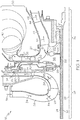
- FIG. 1 is a simplified cross-sectional view of a portion of a gas turbine engine (GTE) 18 including a radial turbine rotor 20 with an internally-cooled, axially-split disk hub, as illustrated in accordance with an exemplary embodiment of the present invention.
- GTE 18 is offered by way of example only to provide a convenient and non-limiting context in which an exemplary embodiment of turbine rotor 20 can be described.
- turbine rotor 20 can be employed within various types of gas turbine engines including, but not limited to, other types of turbofan, turboprop, turboshaft, and turbojet engines, whether deployed onboard an aircraft, watercraft, or ground vehicle (e.g., a tank), included within an auxiliary power unit, included within industrial power generators, or utilized within another platform or application.
- FIG. 1 is presented in the context of a radial-flow turbine rotor configuration, other embodiments may be implanted in various axial-flow turbine rotor configurations.
- such axial-flow turbine rotor engine designs are not presented herein in detail, but the reader is directed to commonly-assigned U.S.
- Patent Application Publication 2013/0034433 and in particular FIG. 1 thereof, for an exemplary, non-limiting axial-flow turbine rotor design.
- FIG. 3 is an axial-flow turbine rotor configuration, suitable for use in the gas turbine engine shown in the above-noted Application Publication.
- GTE 18 is illustrated as a two spool engine including a low pressure (LP) shaft 22 and a high pressure (HP) shaft 24.
- LP shaft 22 and HP shaft 24 are co-axial; that is, LP shaft 22 extends through a longitudinal channel provided through HP shaft 24 along a rotational axis 26.
- GTE 18 further includes a compressor section 28, a combustion section 30, and a turbine section 32, each of which is only partially shown in FIG. 1 .
- An HP compressor 29 is included within compressor section 28 and mounted to the upstream or forward end of HP shaft 24.
- Radial turbine rotor 20, which is contained within turbine section 32, is mounted to the opposing, aft end of HP shaft 24 as the HP turbine.
- compressor section 28 and turbine section 32 may further include an LP compressor and an LP turbine, respectively, which may be mounted to opposing ends of LP shaft 22.
- airflow is received from a non-illustrated intake section included within GTE 18 and supplied to compressor section 28.
- a compressor section duct 36 guides the pressurized airflow through HP compressor 29, which further compresses the airflow prior to discharge into combustion section 30.
- the compressed airflow is directed into a combustion chamber (not shown) included within combustion section 30, mixed with fuel, and ignited to produce combustive gasses.
- the combustive gasses expand rapidly, exit combustion section 30 through a turbine scroll 40, and are directed through a duct 27 to radial turbine rotor 20.
- the combustive gas flow drives rotation of radial turbine rotor 20, which drives further rotation of HP shaft 24 and HP compressor 29.
- a turbine section duct 42 directs the combustive gas flow into a turbine nozzle ring 44 (indicated in FIG. 1 by arrows 46).
- Turbine nozzle ring 44 accelerates the combustive gas flow and imparts the gas flow with a desired tangential component prior to reaching an LP turbine (not shown), which is positioned downstream of nozzle ring 44 and mounted to the aft end of LP shaft 22.
- the combustive gas flow drives the rotation of the non-illustrated LP turbine, which drives further rotation of the LP turbine and LP shaft 22.
- shafts 22 and 24 provide power output, which may be utilized in a variety of different manners, depending upon whether GTE 18 assumes the form of a turbofan, turboprop, turboshaft, turbojet engine, or an auxiliary power unit, to list but a few examples.
- the combustive gas flow is then mixed with cooler bypass flow and exhausted from GTE 18.
- the combustive gas flow may be exhausted through a propulsion nozzle to provide forward thrust.
- radial turbine rotor 20 is an integral turbine rotor and internally cooled; that is, the hub is fabricated from at least two discrete portions, which are separated along a plane orthogonal to rotational axis 26 and which are assembled to produce an integral turbine hub.
- radial turbine rotor 20 includes three portions, a forward turbine hub 56, and an aft turbine hub 60 and a bladed ring 59.
- Forward turbine hub 56 and aft turbine hub 60 abut along a generally annular interface, which resides within the plane generally orthogonal to rotational axis 26 and which is referred to herein as "bond line 54."
- Forward turbine hub 56 and aft turbine hub 60 can be metallurgically bonded utilizing, for example, soldering, brazing, welding, or diffusion bonding.
- radial turbine rotor 20 can be split into at least two separate turbine rotors, a forward turbine rotor 50 and aft turbine rotor 52 as shown in FIG 2A , and may be assembled as discrete, non-bonded pieces, which are maintained in engagement utilizing mechanical means or metallurgical bonding.
- mechanical means generally refers to an engagement of a first and a second component by a third component through the application of force.
- forward turbine rotor 50 and aft turbine rotor 52 may be clamped together utilizing, for example, a tie shaft and curvic system (not shown).
- a plurality of bolts or other such fasteners may be employed for such engagement.
- radial turbine rotor 20 offers several advantages not provided by conventional one piece or monolithic turbines, whether axial or radial, and specifically overcomes several disadvantages associated with monolithic radial turbines.
- fabrication e.g., casting and machining
- components can be cast having more complex internal geometries thereby facilitating fabrication of components having internal cooling passages, for example to provide the impingement cooling described herein in greater detail below.
- radial turbine rotor 20 facilitates the formation of internal voids within the central disk of turbine rotor 20, whether created as cast-in features or through strategic removal of material. As a result, the overall mass of radial turbine rotor 20 can be favorably reduced.
- forward turbine hub 56 and aft turbine hub 60 can be fabricated from disparate materials tailored to the disparate operating conditions experienced by the aft and forward sections of rotor hub 56/60 during operation, as still further described below.
- forward turbine rotor 50 and aft turbine rotor 52 can be fabricated from disparate materials tailored to the disparate operating conditions experienced by the aft and forward sections of rotor 20 during operation, as still further described below.
- the two halves of the blades can be thermally and structurally independent which results in reduction in blade thermal stresses.
- the disk of radial turbine rotor 20 can be fabricated to include an internal cooling circuit, which may supply relatively cool airflow to the internal cooling passages formed within the turbine blades, as described more fully below in connection with FIG. 4 .
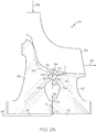
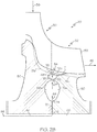
- FIGS. 2A and 2B are cross-sectional views of a portion of radial turbine rotor 20, enlarged from the illustration thereof in FIG. 1 , with FIG. 2A representing an integral turbine rotor and FIG. 2B representing an axially-split turbine rotor.
- the turbine hub 56/60 includes a forward hub section 56, an aft hub section 60, and a plurality of integral blades 59, which are circumferentially spaced around and extend radially outward from hub sections 56/60.
- Bond lines 51a/51b illustrate the bonding region between forward hub section 56, aft hub section 60, and the integral blade 59, as will be described in greater detail below. It will be appreciated by those skilled in the art that FIGS. 2A and 2B are not a truly planar cross-section of the turbine, but rather follows the curvature of the integral blade 59.
- Forward hub section 56 and aft hub section 60 assume the form of generally annular bodies having central openings 64 and 66 therein, respectively, as identified in FIGS. 2A and 2B .
- the inner diameter of central opening 64 provided through forward hub section 56 is generally equivalent to the inner diameter of central opening 66 provided through aft hub section 60.
- a radially-overlapping hub interface (e.g., an annular lap joint) may be provided between forward hub section 56 and aft hub section 60 to radially pilot hub section 56 to forward hub section 60.
- hub sections 56 and 60 combine to form a central hub 56, 60 when radial turbine rotor 20 is assembled.
- Central openings 64 and 66 likewise align when radial turbine rotor 20 is assembled to define a central opening 64, 66 through radial turbine rotor 20.
- a spool e.g., high pressure shaft 24 of GTE 18
- Radial turbine rotor 20 is fixedly mounted to the gas turbine engine spool utilizing, for example, a curvic-type attachment.
- the integral turbine rotor 20 can be readily fabricated to include two inner disk cavities 68a, 70a and 68b, 70b (shown in FIG. 2A ) for mass reduction and for impingement cooling purposes, respectively.
- material may be removed from the back or trailing face of forward hub section 56 to form a first annular cavity or groove 68a therein. Additional material may be removed to form a second, smaller annular cavity or groove 68b therein.
- material may be removed from the front or leading face of aft hub section 60 to form a first annular cavity or groove 70a therein.
- annular cavity or groove 70b therein.
- the trailing face of forward hub section 56 is positioned adjacent the leading face of aft hub section 60 , and grooves 68a and 70a, and 68b and 70b cooperate to define a first annular cavity 68a, 70a and a second annular cavity 68b, 70b within radial turbine rotor 20.
- Inner annular cavities 68a, 70a and 68b, 70b are fully contained within radial turbine rotor 20. Consequently, the provision of the annular cavities has minimal impact on the overall structural integrity of radial turbine rotor 20.
- grooves 68a, 70a, 68b, and 70b can be fabricated as integral cast-in features.
- Annular cavity 68b, 70b may have a generally circular, elliptical, or ovoid radial cross-section, as shown in FIGS. 2A and 2B .
- the creation of an internal cavity or cavities within radial turbine rotor 20 facilitates the formation the hub cooling passages for impingement cooling through central hub 56, 60 of radial turbine rotor 20, as described below.
- annular cavity 68a, 70a may be fluidly coupled to the inlet 63 of an impingement flow passage 65 formed within the hub 56, 60 and to the outlet of a cooling air flow passage 72 also formed within the hub 56, 60.
- airflow may be bled from a section of the engine upstream of combustion section 30; e.g., as indicated in FIG. 1 by arrows 80, a portion of the airflow flowing within compressor section duct 36 may be diverted into outlet 82 of a combustion bypass conduit 84. A portion of this cooler bypass airflow may be directed via an aperture in the conduit toward the leading edge of forward hub section 56 to provide saddle region cooling (indicated in FIG.
- cooling air flow 88 may be turbulated prior to entering HP shaft 24. Turbulating features may be machined or cut into the turbine rotor prior to the region where the cooling air flows into HP shaft 24 (not shown). Additionally, in the case of the axially split rotor, annular cavity 68b, 70b may be fluidly coupled to the inlet or inlets of one or more cooling flow passages formed within blade segments 59.
- disk rims are indirectly cooled by conduction to the cooler disk below.
- This indirect cooling is accomplished by cooling the forward and aft surfaces of the disk below the gas path with purge flow introduced into the disk cavities to prevent gas ingestion.
- This indirect cooling is limited in its effectiveness to control disk rim temperatures.
- the rim is heavily scrubbed by high velocity gas path flow and without a similarly powerful cooling mechanism, the rim temperature is sensitive to engine-to-engine radial profile variations and a host of secondary flow control variables such as the flow discouragers' axial and radial position throughout the operating envelope that affects the rim region's thermal boundary conditions.
- the radial turbine's longer mid-rim region is particularly difficult to cool by conduction due to its greater surface exposure to the gas path combined with its significantly greater distance from the forward and aft disk faces.
- the impingement cooling stream thus impinges at high speed against the radial surface 75 to provide impingement cooling thereto.
- the annular cavity 68b, 70b is located beneath the region of high gas path acceleration, just forward of the aforementioned "throat" region of the hot air flow 38 passage along the surface of radial turbine rotor 20 between blades 59, which experiences high heating due to the local acceleration of the air therealong. (In axial rotors with its shorter flow path, the cavity is directly beneath the throat region).
- impingement cooling at surface 75 heat is conducted from the surface of radial turbine rotor 20 in the throat region to allow such region to operate at a desirably lower temperature.
- a secondary cooling benefit may thus be achieved by virtue of the cooling air exit flow as it reaches the hub outer surface at the throat region
- forward hub section 56 and aft hub section 60 may be fabricated from disparate materials tailored to the disparate operating conditions experienced by the aft and fore sections of the rotor hubs 56/60 .
- forward hub section 56 may be fabricated from a metal or alloy, such as a nickel-based superalloy, having a relatively high density and thermal tolerance.
- aft hub section 60 may be fabricated from a metal or alloy having a lower thermal tolerance (e.g., a titanium-based superalloy) and a lower density.
- turbine rotor 20 can be maximized to improve various measures of engine performance (e.g., specific fuel consumption and power density), while the overall weight of turbine rotor 20 is reduced as compared to a monolithic or single piece turbine rotor fabricated entirely from a heavier superalloy having higher thermal tolerances. Criteria other than relative densities and thermal tolerances may be utilized to select the material or materials from which aft hub section 56 and forward hub section 60 are fabricated. For example, as mechanical stress arising from centrifugal forces will typically concentrate in forward hub section 56, hub section 56 may be fabricated from a material having a relatively high mechanical strength to decrease the likelihood of crack formation and propagation, and improve creep resistance, during high speed operation of turbine rotor 20.
- forward and aft hub sections 56 and 60 may be fabricated from the same or similar alloy, but subjected to different process steps (forged and/or heat treated differently) to tailor material properties (e.g., grain sizes) to the particular conditions to which the individual pieces are subjected.
- a ring of blade structures 59 may be formed by metallurgical bonding a series of bladed pieces together.
- bladed ring denotes any structural element or assemblage of structural elements at least a portion of which has a generally arc-shaped or curved geometry and which are able to be arranged in a partial or complete ring formation with a number of like bladed pieces.
- each blade structure 59 is cast from a single crystal superalloy having its crystallographic grain structure oriented to provide optimal mechanical strength in a radial direction.
- an oxidation-resistant, single crystal, nickel-based superalloy may be utilized, such as the nickel-based superalloy commercially identified as "CMSX 4."
- CMSX 4 the nickel-based superalloy commercially identified as "CMSX 4.”
- the bladed ring 59 may be fabricated from other high temperature materials, as well, including equi-axed superalloys.
- the bladed ring may be bonded to a rotor disk (such as may form hub sections 56 or 60) to produce a turbine rotor, such as either an integral turbine rotor 20 as shown in FIGs 1 and 2A , or split rotors 50 and 52 shown in FIG. 2B .
- Bond lines 51a and 51b illustrate such bonding location and orientation with regard to the integral hub 56/60.
- the interior of the monolithic bladed ring may be machined to generally conform with the separately-fabricated rotor disk, which is described below.
- the turbine rotor is preferably fabricated from alloys tailored to the unique operational environment of the rotor components;.
- rotor disk is fabricated from an oxidation-resistant, nickel-based superalloy having relatively high low cycle fatigue properties; while the bladed ring is fabricated from a turbine superalloy having relatively high stress rupture and oxidation-resistant properties.
- the disk forging is split into two halves and the impingement features are machined on each half prior to metallurgically coupling the two halves back together again along bond line 54.
- the outer annular portion of rotor disk may be machined to impart disk with a desired surface finish and an outer diameter approximately equivalent to the inner diameter of machined airfoil ring.
- Machined bladed ring is then fitted onto the machined rotor disk 56/60.
- the leading and trailing annular interfaces between the inner circumference of ring and the outer circumference of disk are sealed by, for example, brazing (or any process to create a vacuum seal between the two parts) to prevent the ingress of air into the ring-disk interface that may otherwise interfere with bonding.
- a HIP diffusion bonding process or other direct thermal bonding process is then carried-out to bond bladed ring to rotor disk and thereby yield a metallurgically-bonded turbine rotor 20.
- a cooling air exit channel 71 may be drilled into the hub , subsequent to the HIP diffusion bonding, to provide an exit path for the cooling air from the impingement cavity.
- the disk forging is split into two halves and the impingement features are machined on each half.
- the outer annular portions of rotor disks may be machined to impart disks with a desired surface finish and an outer diameter approximately equivalent to the inner diameter of machined airfoil rings.
- the machined bladed rings are then fitted onto the machined rotor disks 56 or 60.
- the leading and trailing annular interfaces between the inner circumference of the rings and the outer circumference of the disks are sealed by, for example, brazing (or any process to create a vacuum seal between the two parts) to prevent the ingress of air into the ring-disk interface that may otherwise interfere with bonding.
- a HIP diffusion bonding process or other direct thermal bonding process is then carried-out to bond bladed rings to rotor disks and thereby yield two separate metallurgically-bonded turbine rotors, such as split turbine rotors 50 or 52 shown in FIG. 2A .
- the two turbines are then mechanically coupled together along bond line 54.
- a cooling air exit channel may be drilled into the hub 71, subsequent to the HIP diffusion bonding, to provide an exit path for the cooling air from the impingement cavity.
- FIG. 3 depicts an alternative embodiment of the present disclosure.
- FIG. 3 depicts an exemplary axial-flow integral turbine rotor 120.
- Axial flow turbine rotor generally includes blades 159, hub 156, 160, central opening 164, 166 annular cavity 168a, 170a, and impingement annular cavity 168b, 170b.
- the hub section 156/160 is axially split along split line 154.
- the blades 159 are bonded to the hub along bond lines 151a, 151b.
- air flow 138 impinges upon blades 159, which causes blades 159 and the hub 156, 160 to rotate around an axis.
- cooling air flow 188 enters the annular hub 168a, 170a via cooling air flow passage 172. Therein, the cooling air accumulates and builds pressure, and is forced at high speed though impingement passage 165. The resulting narrow, high-speed impingement cooling air flow impinges upon radial surface 175 of impingement cavity 168b, 170b for impingement cooling of the outer surface of the turbine 120 between the blades 159. The cooling air then exits the impingement cavity 168b, 170 via channel 171.
- the split hub impingement cooling concept can also be applied to cooled bladed rings.
- FIG. 4 depicts a further alternative embodiment of the present disclosure.
- FIG. 4 depicts an exemplary axially-split radial-flow turbine rotor 220.
- the blade 259 is split into two blade segments 258, 262.
- the blade 259 (in particular segments 258, 262 thereof) may be made of different materials for thermal management purposes.
- the blade 259 is internally cooled via a plurality of internal cooling circuits, as will be described below.
- the turbine rotor 220 is axially split along split line 254.
- the blades 259 (in particular segments 258, 262 thereof) are bonded to the hub along bond lines 251a, 251b respectively.
- air flow 238 impinges upon blades 259, which causes blades 259 and the hub 256, 260 to rotate around an axis.
- cooling air flow 288 enters the annular hub 268a, 270a via cooling air flow passage 272. Therein, the cooling air accumulates and builds pressure, and is forced at high speed though impingement passage 265.
- the resulting narrow, high-speed impingement cooling air flow impinges upon radial surface 275 of impingement cavity 268b, 270b for impingement cooling of the outer surface of the turbine 220 between the blades 259.
- axially-split radial turbine rotor 220 is fabricated to include a plurality of internal blade cooling air passages 265, 267. Cooling passages 265, 267 each extend in a serpentine manner through a respective one of blade segment 258, 262.
- the cooling passages 265, 267 include a plurality of conductive/convective cooling features. Cooling air 288 is supplied into the internal blade cooling air passages 265, 267 from the annular impingement cavity 268b, 270b. That is, once the cooling air impinges against radial surface 275, the cooling air (rather than being directed out of the hub via a flow channel as in FIGS.
- cooling air 288 in this embodiment serves the further purpose of internally cooling the blades 259.
- the cooling air finally exits the blade segments 258, 262 via a plurality of vent holes that are fabricated into the blade segments 258, 262.
- the impingement cavity for radial turbine rotors exemplified by 68b and 70b shown in FIGs 2a and 2b may be may be configured as one cavity with circumferentially uninterrupted surfaces or the cavity may be configured as multiple cavities.
- the cavity may be a single cavity, with the advantage of low cost in manufacturing.
- the impingement cavity 68b and 70b may comprise multiple cavities.
- An example may be multiple cavities separated by ribs, each rib extending radially inward from the blade root.
- the ribs serve as structural ties that help stiffen the relatively thin rim section to limit radial deflection and reduce rim stress by spreading the pull-load to the supporting disk below.
- the ribs also increase the surface area that can be convectively cooled and help to cool the disk rim by conduction.
- the impingement cavity for axial turbine rotors exemplified by 168b and 170b shown in FIG. 3 may similarly be configured as one cavity or multiple cavities.
- the cavity may be a single cavity with circumferentially uninterrupted surfaces.
- the axial turbine rotor disk rim is typically slotted between blades with each slot terminating in a stress-relief hole. In this configuration, multiple impingement cavities may be machined, one under each blade root.
Description
- The present invention relates generally to gas turbine engines and, more particularly, to gas turbine engines that incorporate impingement cooling internal to turbine rotors.
- Gas turbine engines ("GTE") have been engineered extensively to improve efficiency, thrust-to-weight ratios, and other measures of engine performance. One of the most direct manners by which engine performance can be improved is through increases in the core rotational speeds and turbine inlet temperatures generated during engine operation. However, as turbine inlet temperatures and rotational speeds increase, so too do the thermal and mechanical demands placed on the GTE components. The most demanding performance requirements are typically placed on the high-pressure turbine rotor or rotors, which are positioned immediately downstream of the GTE combustion section and which rotate at the greatest speed during engine operation. The turbine blades, as well as surface regions of the turbine disk, in particular, are directly exposed to combustive gas flow at or near peak temperatures and are consequently heated to exceedingly high temperatures at which most alloys weaken or melt and become prone to oxidation or other forms of chemical and structural degradation.
- Patent document number
EP2653652A2 describes an integral turbine rotor comprising: a forward hub section; an aft hub section wherein the forward hub section and the aft hub section are coupled to one another along an annular interface that resides within a plane generally orthogonal to a rotational axis of the integral turbine; an airfoil blade ring, which comprises a plurality of integral blades, which are circumferentially spaced around and extend radially outward of the coupled forward and after hub sections, coupled to a radial outer surface of the coupled forward and aft hub sections; an internal hub cavity formed within an interior portion of the coupled forward and aft hub sections, wherein the internal hub cavity is positioned within the interior portion of the coupled forward and aft hub section, and a central opening located radially inward from the internal hub cavity, and a hub cooling air passage, wherein the hub cooling air passage has an axial width that is less than a greatest axial width of the internal hub cavity, and wherein the hub cooling air passage provides fluid connection between the central opening and the internal hub cavity, wherein cooling air flows from the central opening via the cooling air passage into the internal hub cavity. - Patent document number
US4447188A describes a unitary turbine wheel for a gas turbine engine, the turbine wheel including a pair of initially separate discs which are diffusion bonded together and define air passageways which extend radially through the discs. A plurality of initially separate turbine blades are provided each of which defines cooling air passageways, and the turbine blades are diffusion bonded in angularly spaced relationship to the peripheral surfaces of the discs with the air passageways in the blades communicating with the air passageways defined by the discs. Means is provided for drivably connecting the turbine wheel to a turbine shaft, and in a preferred embodiment, the turbine blades have a thermally insulating coating on the exposed surfaces thereof - Alvin N. Hammer et al. describes an integral turbine rotor and more specifically a concept for manufacturing air cooled blades called split blade fabrication. It was developed as an alternative to internal ceramic coring and involves creating an internal cooling cavity without flow dividers by a solid and therefore stronger ceramic plate which can be firmly anchored within the casting shell mold. The concept for split blade fabrication claims an avoidance of excessive casting rejections in a multi-blade wheel and ease of design of different cooling passages [Alvin N. Hammer et al.: "Fabrication of Cooled Radial Turbine Rotor", 1 June 1986, pages 1-342].
- Turbines can be broadly divided into two categories, axial and radial turbines, based upon the direction of airflow received by the turbine relative to the turbine's rotational axis. Each type of turbine has benefits and tradeoffs. For example, relative to axial turbines, radial turbines offer certain performance benefits including reduced aerodynamic loading which enable the turbine to operate at greater efficiencies, and higher tip speeds which reduce relative total temperatures that allow the turbine to operate at higher temperatures. However, due to the nature of their design, radial turbines are relatively lengthy in the axial direction. As a result, some radial turbines can be undesirably heavy and difficult to cool at the disk rim, especially at the mid section. Axial turbines are lighter weight due to shorter axial length but has relatively higher aerodynamic loading. So despite having shorter conduction distance from the sides of the disk hub to the rim, the higher gas path velocities can overwhelm the conduction cooling capability of some axial turbines. Regardless of the configuration, however, present turbine cooling schemes are unable to adequately cool the surface of the disk (between the blades, commonly referred to in the art as the "throat" region) of the turbine, resulting in undesirable high component metal operating temperatures and temperature gradients, especially during start-up and transient operational conditions. For at least these reasons, and despite the proposal of multiple axial and radial turbine designs in the prior art, few currently-implemented gas turbine engine platforms are able to operate at optimally-high temperatures without risking melting, oxidation, and/or other forms of degradation.
- It would thus be desirable to provide a turbine suitable for usage in a gas turbine engine that can operate at elevated turbine inlet temperature levels. It would further be desirable to provide a turbine that has improved inter-blade disk surface region cooling characteristics. Furthermore, other desirable features and characteristics of the invention will become apparent from the subsequent detailed description and the appended claims, taken in conjunction with the accompanying drawings and this background of the invention.
- The present invention in its various aspects is as set out in the appended claims. Embodiments of an integral turbine rotor are provided. In one exemplary, non-limiting embodiment, an integral turbine rotor includes a forward hub section and an aft hub section. The forward hub section and the aft hub section are metallurgically coupled to one another along an annular interface that resides within a plane generally orthogonal to a rotational axis of the integral turbine rotor. The turbine further includes an airfoil blade ring metallurgically coupled to a radial outer surface of the bonded forward and aft hub sections and an impingement cavity formed within an interior portion of the bonded forward and aft hub sections. The impingement cavity includes an interior surface that is positioned proximate to the radial outer surface of the coupled forward and aft hub sections. Further, an impingement cooling air flow impinges against the interior surface of the impingement cavity to provide convective and conductive cooling to the radial outer surface of the bonded forward and aft hub sections.
- This summary is provided to introduce a selection of concepts in a simplified form that are further described below in the detailed description. This summary is not intended to identify key features or essential features of the claimed subject matter, nor is it intended to be used as an aid in determining the scope of the claimed subject matter.
- At least one example of the present invention will hereinafter be described in conjunction with the following figures, wherein like numerals denote like elements, and wherein:
-
FIG. 1 is a simplified cross-sectional schematic illustration of an exemplary gas turbine engine (partially shown) including a radial-flow turbine rotor, as illustrated in accordance with an exemplary embodiment of the present invention; -
FIGS. 2A and2B are cross-sectional views of a portion of a radial turbine rotor, in alternative embodiments; -
FIG. 3 is a simplified cross-sectional schematic illustration of a portion of an axial-flow turbine rotor in accordance with another exemplary embodiment of the present invention; and -
FIG. 4 is a simplified cross-sectional schematic illustration of a portion of a radial-flow turbine rotor that incorporates an internal blade cooling scheme in accordance with yet another exemplary embodiment of the present invention. - The following detailed description is merely exemplary in nature and is not intended to limit the invention or the application and uses of the invention. As used herein, the word "exemplary" means "serving as an example, instance, or illustration." Thus, any embodiment described herein as "exemplary" is not necessarily to be construed as preferred or advantageous over other embodiments. All of the embodiments and implementations of the aluminum alloys and methods for the manufacture thereof described herein are exemplary embodiments provided to enable persons skilled in the art to make or use the invention and not to limit the scope of the invention, which is defined by the claims. Furthermore, there is no intention to be bound by any expressed or implied theory presented in the preceding technical field, background, brief summary, or the following detailed description.
-
FIG. 1 is a simplified cross-sectional view of a portion of a gas turbine engine (GTE) 18 including aradial turbine rotor 20 with an internally-cooled, axially-split disk hub, as illustrated in accordance with an exemplary embodiment of the present invention. As illustrated inFIG. 1 and described herein, GTE 18 is offered by way of example only to provide a convenient and non-limiting context in which an exemplary embodiment ofturbine rotor 20 can be described. It will be readily appreciated that embodiments ofturbine rotor 20 can be employed within various types of gas turbine engines including, but not limited to, other types of turbofan, turboprop, turboshaft, and turbojet engines, whether deployed onboard an aircraft, watercraft, or ground vehicle (e.g., a tank), included within an auxiliary power unit, included within industrial power generators, or utilized within another platform or application. Furthermore, it will be readily appreciated that althoughFIG. 1 is presented in the context of a radial-flow turbine rotor configuration, other embodiments may be implanted in various axial-flow turbine rotor configurations. For simplicity, such axial-flow turbine rotor engine designs are not presented herein in detail, but the reader is directed to commonly-assignedU.S. Patent Application Publication 2013/0034433 , and in particularFIG. 1 thereof, for an exemplary, non-limiting axial-flow turbine rotor design. Further, it is noted that the embodiment depicted in the present disclosure inFIG. 3 is an axial-flow turbine rotor configuration, suitable for use in the gas turbine engine shown in the above-noted Application Publication. - In the exemplary embodiment shown in
FIG. 1 , GTE 18 is illustrated as a two spool engine including a low pressure (LP)shaft 22 and a high pressure (HP)shaft 24.LP shaft 22 and HPshaft 24 are co-axial; that is,LP shaft 22 extends through a longitudinal channel provided throughHP shaft 24 along arotational axis 26. GTE 18 further includes acompressor section 28, a combustion section 30, and aturbine section 32, each of which is only partially shown inFIG. 1 . An HPcompressor 29 is included withincompressor section 28 and mounted to the upstream or forward end of HPshaft 24.Radial turbine rotor 20, which is contained withinturbine section 32, is mounted to the opposing, aft end ofHP shaft 24 as the HP turbine. Although not shown inFIG. 1 for clarity,compressor section 28 andturbine section 32 may further include an LP compressor and an LP turbine, respectively, which may be mounted to opposing ends ofLP shaft 22. - During engine operation, airflow is received from a non-illustrated intake section included within
GTE 18 and supplied tocompressor section 28. As indicated inFIG. 1 byarrows 34, acompressor section duct 36 guides the pressurized airflow through HPcompressor 29, which further compresses the airflow prior to discharge into combustion section 30. The compressed airflow is directed into a combustion chamber (not shown) included within combustion section 30, mixed with fuel, and ignited to produce combustive gasses. As indicated inFIG. 1 byarrows 38, the combustive gasses expand rapidly, exit combustion section 30 through aturbine scroll 40, and are directed through aduct 27 toradial turbine rotor 20. The combustive gas flow drives rotation ofradial turbine rotor 20, which drives further rotation ofHP shaft 24 andHP compressor 29. After flowing throughradial turbine rotor 20, aturbine section duct 42 directs the combustive gas flow into a turbine nozzle ring 44 (indicated inFIG. 1 by arrows 46).Turbine nozzle ring 44 accelerates the combustive gas flow and imparts the gas flow with a desired tangential component prior to reaching an LP turbine (not shown), which is positioned downstream ofnozzle ring 44 and mounted to the aft end ofLP shaft 22. The combustive gas flow drives the rotation of the non-illustrated LP turbine, which drives further rotation of the LP turbine andLP shaft 22. Collectively, the rotation ofshafts GTE 18 assumes the form of a turbofan, turboprop, turboshaft, turbojet engine, or an auxiliary power unit, to list but a few examples. The combustive gas flow is then mixed with cooler bypass flow and exhausted fromGTE 18. For example, in the case of turbofan and turbojet engine, the combustive gas flow may be exhausted through a propulsion nozzle to provide forward thrust. - As indicated above,
radial turbine rotor 20 is an integral turbine rotor and internally cooled; that is, the hub is fabricated from at least two discrete portions, which are separated along a plane orthogonal torotational axis 26 and which are assembled to produce an integral turbine hub. In the exemplary embodiment illustrated inFIG. 1 , specifically,radial turbine rotor 20 includes three portions, aforward turbine hub 56, and an aft turbine hub 60 and abladed ring 59. The aft face offorward turbine hub 56 and the forward face of aft turbine hub 60 abut along a generally annular interface, which resides within the plane generally orthogonal torotational axis 26 and which is referred to herein as "bond line 54."Forward turbine hub 56 and aft turbine hub 60 can be metallurgically bonded utilizing, for example, soldering, brazing, welding, or diffusion bonding. - In an alternative embodiment,
radial turbine rotor 20 can be split into at least two separate turbine rotors, aforward turbine rotor 50 andaft turbine rotor 52 as shown inFIG 2A , and may be assembled as discrete, non-bonded pieces, which are maintained in engagement utilizing mechanical means or metallurgical bonding. As used herein, the term "mechanical means" generally refers to an engagement of a first and a second component by a third component through the application of force. For example,forward turbine rotor 50 andaft turbine rotor 52 may be clamped together utilizing, for example, a tie shaft and curvic system (not shown). Alternatively, a plurality of bolts or other such fasteners (not shown) may be employed for such engagement. - The split-hub design of
radial turbine rotor 20 offers several advantages not provided by conventional one piece or monolithic turbines, whether axial or radial, and specifically overcomes several disadvantages associated with monolithic radial turbines. First, by assemblingradial turbine rotor 20 from multiple pieces, fabrication (e.g., casting and machining) of the turbine pieces can be enhanced. In particular, by reducing casting volume, components can be cast having more complex internal geometries thereby facilitating fabrication of components having internal cooling passages, for example to provide the impingement cooling described herein in greater detail below. Second, the multi-piece construction ofradial turbine rotor 20 facilitates the formation of internal voids within the central disk ofturbine rotor 20, whether created as cast-in features or through strategic removal of material. As a result, the overall mass ofradial turbine rotor 20 can be favorably reduced. Third, in the case of the split hub design ofradial turbine rotor 20,forward turbine hub 56 and aft turbine hub 60 can be fabricated from disparate materials tailored to the disparate operating conditions experienced by the aft and forward sections ofrotor hub 56/60 during operation, as still further described below. - Fourth, in the case of the axially-split design of radial turbine rotor 20 (
FIG. 2B ),forward turbine rotor 50 andaft turbine rotor 52 can be fabricated from disparate materials tailored to the disparate operating conditions experienced by the aft and forward sections ofrotor 20 during operation, as still further described below. Fifth, in the case of the axially-split design of the radial turbine rotor, the two halves of the blades can be thermally and structurally independent which results in reduction in blade thermal stresses. Additionally, the disk ofradial turbine rotor 20 can be fabricated to include an internal cooling circuit, which may supply relatively cool airflow to the internal cooling passages formed within the turbine blades, as described more fully below in connection withFIG. 4 . -
FIGS. 2A and2B are cross-sectional views of a portion ofradial turbine rotor 20, enlarged from the illustration thereof inFIG. 1 , withFIG. 2A representing an integral turbine rotor andFIG. 2B representing an axially-split turbine rotor. As can be seen inFIGS. 2A and2B , theturbine hub 56/60 includes aforward hub section 56, an aft hub section 60, and a plurality ofintegral blades 59, which are circumferentially spaced around and extend radially outward fromhub sections 56/60.Bond lines 51a/51b illustrate the bonding region betweenforward hub section 56, aft hub section 60, and theintegral blade 59, as will be described in greater detail below. It will be appreciated by those skilled in the art thatFIGS. 2A and2B are not a truly planar cross-section of the turbine, but rather follows the curvature of theintegral blade 59. -
Forward hub section 56 and aft hub section 60 assume the form of generally annular bodies havingcentral openings FIGS. 2A and2B . In the illustrated example shown inFIGS. 1 ,2A and2B , the inner diameter ofcentral opening 64 provided throughforward hub section 56 is generally equivalent to the inner diameter ofcentral opening 66 provided through aft hub section 60. Whenradial turbine rotor 20 is assembled,forward hub section 56 aligns axially with aft hub section 60 and, preferably, radially pilots thereto. Although not shown inFIGS. 1 ,2A , and2B for clarity, a radially-overlapping hub interface (e.g., an annular lap joint) may be provided betweenforward hub section 56 and aft hub section 60 to radiallypilot hub section 56 to forward hub section 60. In this manner,hub sections 56 and 60 combine to form acentral hub 56, 60 whenradial turbine rotor 20 is assembled.Central openings radial turbine rotor 20 is assembled to define acentral opening radial turbine rotor 20. Whenradial turbine 20 rotor is installed within GTE 18 (FIG. 1 ), a spool (e.g.,high pressure shaft 24 of GTE 18) extends through this longitudinal channel.Radial turbine rotor 20 is fixedly mounted to the gas turbine engine spool utilizing, for example, a curvic-type attachment. - By virtue of its multi-piece construction, the
integral turbine rotor 20 can be readily fabricated to include twoinner disk cavities FIG. 2A ) for mass reduction and for impingement cooling purposes, respectively. For example, as indicated inFIGS. 1 ,2A , and2B , material may be removed from the back or trailing face offorward hub section 56 to form a first annular cavity orgroove 68a therein. Additional material may be removed to form a second, smaller annular cavity orgroove 68b therein. Similarly, material may be removed from the front or leading face of aft hub section 60 to form a first annular cavity orgroove 70a therein. Additional material may be removed to form a second, smaller annular cavity orgroove 70b therein. Whenradial turbine rotor 20 is assembled, the trailing face offorward hub section 56 is positioned adjacent the leading face of aft hub section 60 , andgrooves annular cavity annular cavity radial turbine rotor 20. Innerannular cavities radial turbine rotor 20. Consequently, the provision of the annular cavities has minimal impact on the overall structural integrity ofradial turbine rotor 20. In further embodiments,grooves Annular cavity FIGS. 2A and2B . Notably, the creation of an internal cavity or cavities withinradial turbine rotor 20 facilitates the formation the hub cooling passages for impingement cooling throughcentral hub 56, 60 ofradial turbine rotor 20, as described below. - As shown in
FIGS. 2A and2B ,annular cavity inlet 63 of animpingement flow passage 65 formed within thehub 56, 60 and to the outlet of a coolingair flow passage 72 also formed within thehub 56, 60. During operation of GTE 18 (FIG. 1 ), airflow may be bled from a section of the engine upstream of combustion section 30; e.g., as indicated inFIG. 1 byarrows 80, a portion of the airflow flowing withincompressor section duct 36 may be diverted intooutlet 82 of a combustion bypass conduit 84. A portion of this cooler bypass airflow may be directed via an aperture in the conduit toward the leading edge offorward hub section 56 to provide saddle region cooling (indicated inFIG. 1 by arrow 86), while the remainder other bypass air (indicated by arrow 88) may be directed radially inward toward the engine centerline, flow axially alongHP shaft 24, and may ultimately flow intoinlet 76 of the hub coolingair passages 72 to provide cooling ofhub 56, 60. (In an alternative embodiment, a TOBI system that processes compressor discharge air may be employed to provide cooling air). In some embodiments, the coolingair flow 88 may be turbulated prior to enteringHP shaft 24. Turbulating features may be machined or cut into the turbine rotor prior to the region where the cooling air flows into HP shaft 24 (not shown). Additionally, in the case of the axially split rotor,annular cavity blade segments 59. - In the prior art, disk rims, particularly the mid-rim region, are indirectly cooled by conduction to the cooler disk below. This indirect cooling is accomplished by cooling the forward and aft surfaces of the disk below the gas path with purge flow introduced into the disk cavities to prevent gas ingestion. This indirect cooling is limited in its effectiveness to control disk rim temperatures. The rim is heavily scrubbed by high velocity gas path flow and without a similarly powerful cooling mechanism, the rim temperature is sensitive to engine-to-engine radial profile variations and a host of secondary flow control variables such as the flow discouragers' axial and radial position throughout the operating envelope that affects the rim region's thermal boundary conditions. The radial turbine's longer mid-rim region is particularly difficult to cool by conduction due to its greater surface exposure to the gas path combined with its significantly greater distance from the forward and aft disk faces.
- In embodiments of the present disclosure as illustrated in
FIGS. 2A and2B , such mid-rim cooling difficulties that are encountered in the prior art are addressed in the following manner: air flows through coolingair passage 72 after which it enters intoannular cavity outlet 63 ofannular cavity impingement flow passage 65. Due to the air pressure that accumulates withinannular cavity GTE 18, cooling air is accelerated very quickly throughimpingement flow passage 65. Upon reaching the outlet ofimpingement flow passage 65, the cooling air has formed a narrow, high-speed impingement cooling stream that is directed at aradial surface 75 ofannular cavity radial surface 75 to provide impingement cooling thereto. It is noted that theannular cavity hot air flow 38 passage along the surface ofradial turbine rotor 20 betweenblades 59, which experiences high heating due to the local acceleration of the air therealong. (In axial rotors with its shorter flow path, the cavity is directly beneath the throat region). Thus, by impingement cooling atsurface 75, heat is conducted from the surface ofradial turbine rotor 20 in the throat region to allow such region to operate at a desirably lower temperature. After impingement cooling, the cooling air exitsannular cavity channel 71, which may be drilled into theturbine rotor 20 after the formation thereof. A secondary cooling benefit may thus be achieved by virtue of the cooling air exit flow as it reaches the hub outer surface at the throat region - In some embodiments,
forward hub section 56 and aft hub section 60 may be fabricated from disparate materials tailored to the disparate operating conditions experienced by the aft and fore sections of therotor hubs 56/60 . For example, as the temperatures to whichforward hub section 56 is exposed will typically be significantly higher than the temperatures to which aft hub section 60 is exposed,forward hub section 56 may be fabricated from a metal or alloy, such as a nickel-based superalloy, having a relatively high density and thermal tolerance. In contrast, aft hub section 60 may be fabricated from a metal or alloy having a lower thermal tolerance (e.g., a titanium-based superalloy) and a lower density. In this manner, the temperature capabilities ofturbine rotor 20 can be maximized to improve various measures of engine performance (e.g., specific fuel consumption and power density), while the overall weight ofturbine rotor 20 is reduced as compared to a monolithic or single piece turbine rotor fabricated entirely from a heavier superalloy having higher thermal tolerances. Criteria other than relative densities and thermal tolerances may be utilized to select the material or materials from whichaft hub section 56 and forward hub section 60 are fabricated. For example, as mechanical stress arising from centrifugal forces will typically concentrate inforward hub section 56,hub section 56 may be fabricated from a material having a relatively high mechanical strength to decrease the likelihood of crack formation and propagation, and improve creep resistance, during high speed operation ofturbine rotor 20. Additionally, forward andaft hub sections 56 and 60 may be fabricated from the same or similar alloy, but subjected to different process steps (forged and/or heat treated differently) to tailor material properties (e.g., grain sizes) to the particular conditions to which the individual pieces are subjected. - In some embodiments, a ring of
blade structures 59 may be formed by metallurgical bonding a series of bladed pieces together. As utilized herein, the term "bladed ring" denotes any structural element or assemblage of structural elements at least a portion of which has a generally arc-shaped or curved geometry and which are able to be arranged in a partial or complete ring formation with a number of like bladed pieces. In a preferred embodiment, eachblade structure 59 is cast from a single crystal superalloy having its crystallographic grain structure oriented to provide optimal mechanical strength in a radial direction. By way of non-limiting example, an oxidation-resistant, single crystal, nickel-based superalloy may be utilized, such as the nickel-based superalloy commercially identified as "CMSX 4." This notwithstanding, the bladedring 59 may be fabricated from other high temperature materials, as well, including equi-axed superalloys. - After fabrication of the bladed ring, the bladed ring may be bonded to a rotor disk (such as may form
hub sections 56 or 60) to produce a turbine rotor, such as either anintegral turbine rotor 20 as shown inFIGs 1 and2A , or splitrotors FIG. 2B .Bond lines integral hub 56/60. The interior of the monolithic bladed ring may be machined to generally conform with the separately-fabricated rotor disk, which is described below. - The turbine rotor is preferably fabricated from alloys tailored to the unique operational environment of the rotor components;. In one implementation, rotor disk is fabricated from an oxidation-resistant, nickel-based superalloy having relatively high low cycle fatigue properties; while the bladed ring is fabricated from a turbine superalloy having relatively high stress rupture and oxidation-resistant properties.. The disk forging is split into two halves and the impingement features are machined on each half prior to metallurgically coupling the two halves back together again along
bond line 54. After production of the rotor disk forging, the outer annular portion of rotor disk may be machined to impart disk with a desired surface finish and an outer diameter approximately equivalent to the inner diameter of machined airfoil ring. Machined bladed ring is then fitted onto the machinedrotor disk 56/60. The leading and trailing annular interfaces between the inner circumference of ring and the outer circumference of disk are sealed by, for example, brazing (or any process to create a vacuum seal between the two parts) to prevent the ingress of air into the ring-disk interface that may otherwise interfere with bonding. A HIP diffusion bonding process or other direct thermal bonding process is then carried-out to bond bladed ring to rotor disk and thereby yield a metallurgically-bondedturbine rotor 20. As noted above, a coolingair exit channel 71 may be drilled into the hub , subsequent to the HIP diffusion bonding, to provide an exit path for the cooling air from the impingement cavity. - In another implementation, the disk forging is split into two halves and the impingement features are machined on each half. After production of the rotor disk forgings, the outer annular portions of rotor disks may be machined to impart disks with a desired surface finish and an outer diameter approximately equivalent to the inner diameter of machined airfoil rings. The machined bladed rings are then fitted onto the machined
rotor disks 56 or 60. The leading and trailing annular interfaces between the inner circumference of the rings and the outer circumference of the disks are sealed by, for example, brazing (or any process to create a vacuum seal between the two parts) to prevent the ingress of air into the ring-disk interface that may otherwise interfere with bonding. A HIP diffusion bonding process or other direct thermal bonding process is then carried-out to bond bladed rings to rotor disks and thereby yield two separate metallurgically-bonded turbine rotors, such assplit turbine rotors FIG. 2A . The two turbines are then mechanically coupled together alongbond line 54. As noted above, a cooling air exit channel may be drilled into thehub 71, subsequent to the HIP diffusion bonding, to provide an exit path for the cooling air from the impingement cavity. -
FIG. 3 depicts an alternative embodiment of the present disclosure. InFIG. 3 , for ease of reference, like numerals have been incremented by 100.FIG. 3 depicts an exemplary axial-flowintegral turbine rotor 120. Axial flow turbine rotor generally includesblades 159,hub 156, 160,central opening annular cavity annular cavity 168b, 170b. Thehub section 156/160 is axially split alongsplit line 154. Theblades 159 are bonded to the hub alongbond lines air flow 138 impinges uponblades 159, which causesblades 159 and thehub 156, 160 to rotate around an axis. As described above with regard toFIGS. 2A and2B , coolingair flow 188 enters theannular hub air flow passage 172. Therein, the cooling air accumulates and builds pressure, and is forced at high speed thoughimpingement passage 165. The resulting narrow, high-speed impingement cooling air flow impinges uponradial surface 175 ofimpingement cavity 168b, 170b for impingement cooling of the outer surface of theturbine 120 between theblades 159. The cooling air then exits theimpingement cavity 168b, 170 viachannel 171. The split hub impingement cooling concept can also be applied to cooled bladed rings. -
FIG. 4 depicts a further alternative embodiment of the present disclosure. InFIG. 4 , for ease of reference, like numerals have been incremented by a further 100.FIG. 4 depicts an exemplary axially-split radial-flow turbine rotor 220. In contrast toradial turbine rotor 20 depicted inFIG. 2 , theblade 259 is split into twoblade segments hub particular segments radial turbine rotor 20 depicted inFIG. 2 , theblade 259 is internally cooled via a plurality of internal cooling circuits, as will be described below. - With continue reference to
FIG. 4 , theturbine rotor 220 is axially split alongsplit line 254. The blades 259 (inparticular segments bond lines air flow 238 impinges uponblades 259, which causesblades 259 and thehub FIGS. 2A and2B , coolingair flow 288 enters theannular hub air flow passage 272. Therein, the cooling air accumulates and builds pressure, and is forced at high speed thoughimpingement passage 265. The resulting narrow, high-speed impingement cooling air flow impinges uponradial surface 275 ofimpingement cavity turbine 220 between theblades 259. - With reference to
FIG. 4 , axially-splitradial turbine rotor 220 is fabricated to include a plurality of internal blade coolingair passages passages blade segment cooling passages Cooling air 288 is supplied into the internal blade coolingair passages annular impingement cavity radial surface 275, the cooling air (rather than being directed out of the hub via a flow channel as inFIGS. 2A ,2B , and3 ) is directed viachannels 271a, 271b into internal blade coolingair passages air 288 in this embodiment serves the further purpose of internally cooling theblades 259. The cooling air finally exits theblade segments blade segments - The impingement cavity for radial turbine rotors exemplified by 68b and 70b shown in
FIGs 2a and2b may be may be configured as one cavity with circumferentially uninterrupted surfaces or the cavity may be configured as multiple cavities. In moderately stressed radial turbine rotors, the cavity may be a single cavity, with the advantage of low cost in manufacturing. In highly stressed radial turbine rotors, theimpingement cavity - The impingement cavity for axial turbine rotors exemplified by 168b and 170b shown in
FIG. 3 may similarly be configured as one cavity or multiple cavities. In low cost or limited-life application axial turbine rotors, the cavity may be a single cavity with circumferentially uninterrupted surfaces. In highly stressed or long-life applications, the axial turbine rotor disk rim is typically slotted between blades with each slot terminating in a stress-relief hole. In this configuration, multiple impingement cavities may be machined, one under each blade root. - Thus it will be appreciated that the foregoing embodiments described in this disclosure have provided improved gas turbine engines that exhibit improved mid-disk rim cooling through the use of impingement cooling within the disk. This improved cooling allows the turbines to be operated at an optimally higher temperature, while suffering less thermal degradation.
- While at least one exemplary embodiment has been presented in the foregoing detailed description, it should be appreciated that a vast number of variations exist. It should also be appreciated that the exemplary embodiment or exemplary embodiments are only examples, and are not intended to limit the scope, applicability, or configuration of the invention in any way. Rather, the foregoing detailed description will provide those skilled in the art with a convenient road map for implementing an exemplary embodiment of the invention. It being understood that various changes may be made in the function and arrangement of elements described in an exemplary embodiment without departing from the scope of the invention as set-forth in the appended claims.
Claims (7)
- An integral turbine rotor (20) comprising:a forward hub section (56);an aft hub section (60), wherein the forward hub section (56) and the aft hub section (60) are coupled to one another along an annular interface that resides within a plane generally orthogonal to a rotational axis (26) of the integral turbine (20);an airfoil blade ring, which comprises a plurality of integral blades, which are circumferentially spaced around and extend radially outward of the coupled forward and after hub sections (56, 60), coupled to a radial outer surface of the coupled forward and aft hub sections (56, 60); andan impingement cavity (68b, 70b) formed within an interior portion of the coupled forward and aft hub sections (56, 60), wherein the impingement cavity (68b, 70b) comprises an interior surface (75) that is positioned proximate to the radial outer surface of the coupled forward and aft hub sections (56, 60);an impingement air flow channel (65) in fluid communication with the impingement cavity (68b, 70b), wherein cooling air is accelerated and narrowed as it flows through the impingement air flow channel (65) to produce the impingement cooling air flow;an internal hub cavity (68a, 70a) formed within an interior portion of the coupled forward and aft hub sections (56, 60) that is in fluid communication with the impingement air flow channel (65), wherein cooling air (88) flows from the internal hub cavity (68a, 70a) into the impingement air flow channel (65), wherein the internal hub cavity (68a, 70a) is positioned radially-inward from the impingement cavity (68b, 70b) within the interior portion of the coupled forward and aft hub section (56, 60), wherein the impingement air flow channel (65) has an axial width that is less than a greatest axial width of both the impingement cavity (68b, 70b) and the internal hub cavity (68a, 70a), and wherein the impingement air flow channel (65) provides fluid connection between the internal hub cavity (68a, 70a) and the impingement cavity (68b, 70b),wherein an impingement cooling air flow impinges against the interior surface (75) of the impingement cavity (68b, 70b) to provide convective and conductive cooling to the radial outer surface of the coupled forward and aft hub sections; anda central opening (64, 66) located radially inward from the internal hub cavity, and a hub cooling air passage (72), wherein the hub cooling air passage has an axial width that is less than a greatest axial width of both the impingement cavity (68b, 70b) and the internal hub cavity (68a, 70a), and wherein the hub cooling air passage provides fluid connection between the central opening (64, 66) and the internal hub cavity (68a, 70a).
- The integral turbine rotor of claim 1 , wherein the interior surface (75) of the impingement cavity (68b, 70b) is positioned proximate to an axially mid portion of the outer surface of the coupled forward and aft hub section (56, 60).
- The integral turbine rotor of claim 2, wherein the impingement cavity (68b, 70b) is positioned along the annular interface where the forward and the aft hub sections (56, 60) are coupled.
- The integral turbine rotor of claim 1, wherein the impingement air flow channel (65) is positioned along the annular interface where the forward and the aft hub sections (56, 60) are coupled.
- The integral turbine rotor of claim 1, further comprising a cooling air flow exit channel (71) in fluid communication with the impingement cavity (68b, 70b) and extending between the impingement cavity (68b, 70b) and the radial outer surface of the coupled forward and aft hub sections (56, 60), wherein cooling air flow exits the turbine through the cooling air flow exit channel (71) subsequent to impinging upon the interior surface (75) of the impingement cavity (68b, 70b).
- The integral turbine rotor of claim 1, wherein the forward hub section (56) comprises a first metal alloy and the aft hub section (60) comprises a second metal alloy that may be different or identical from the first metal alloy.
- The integral turbine of claim 1, wherein an axially-oriented central openings (64, 66) are radially inward of the coupled forward and aft hub sections is in fluid communication with a compressor bypass duct for providing compressor bypass air as the cooling air.
Applications Claiming Priority (1)
| Application Number | Priority Date | Filing Date | Title |
|---|---|---|---|
| US13/892,828 US9476305B2 (en) | 2013-05-13 | 2013-05-13 | Impingement-cooled turbine rotor |
Publications (3)
| Publication Number | Publication Date |
|---|---|
| EP2803820A2 EP2803820A2 (en) | 2014-11-19 |
| EP2803820A3 EP2803820A3 (en) | 2015-01-21 |
| EP2803820B1 true EP2803820B1 (en) | 2017-01-25 |
Family
ID=50549052
Family Applications (1)
| Application Number | Title | Priority Date | Filing Date |
|---|---|---|---|
| EP14166274.2A Active EP2803820B1 (en) | 2013-05-13 | 2014-04-28 | Impingement-cooled integral turbine rotor |
Country Status (2)
| Country | Link |
|---|---|
| US (1) | US9476305B2 (en) |
| EP (1) | EP2803820B1 (en) |
Families Citing this family (16)
| Publication number | Priority date | Publication date | Assignee | Title |
|---|---|---|---|---|
| US9033670B2 (en) * | 2012-04-11 | 2015-05-19 | Honeywell International Inc. | Axially-split radial turbines and methods for the manufacture thereof |
| EP2837769B1 (en) * | 2013-08-13 | 2016-06-29 | Alstom Technology Ltd | Rotor shaft for a turbomachine |
| US9850760B2 (en) | 2015-04-15 | 2017-12-26 | Honeywell International Inc. | Directed cooling for rotating machinery |
| US10260355B2 (en) * | 2016-03-07 | 2019-04-16 | Honeywell International Inc. | Diverging-converging cooling passage for a turbine blade |
| US10024170B1 (en) * | 2016-06-23 | 2018-07-17 | Florida Turbine Technologies, Inc. | Integrally bladed rotor with bore entry cooling holes |
| US10458242B2 (en) * | 2016-10-25 | 2019-10-29 | Pratt & Whitney Canada Corp. | Rotor disc with passages |
| US10837287B2 (en) * | 2017-01-20 | 2020-11-17 | Pratt & Whitney Canada Corp. | Mistuned bladed rotor and associated manufacturing method |
| US10876407B2 (en) * | 2017-02-16 | 2020-12-29 | General Electric Company | Thermal structure for outer diameter mounted turbine blades |
| CN110637151B (en) | 2017-10-31 | 2021-09-07 | 三菱重工发动机和增压器株式会社 | Turbine rotor blade, turbocharger, and method for manufacturing turbine rotor blade |
| US10794190B1 (en) | 2018-07-30 | 2020-10-06 | Florida Turbine Technologies, Inc. | Cast integrally bladed rotor with bore entry cooling |
| US10927676B2 (en) * | 2019-02-05 | 2021-02-23 | Pratt & Whitney Canada Corp. | Rotor disk for gas turbine engine |
| US11428160B2 (en) | 2020-12-31 | 2022-08-30 | General Electric Company | Gas turbine engine with interdigitated turbine and gear assembly |
| US11591916B2 (en) * | 2021-07-02 | 2023-02-28 | Hamilton Sundstrand Corporation | Radial turbine rotor with complex cooling channels and method of making same |
| US11506060B1 (en) | 2021-07-15 | 2022-11-22 | Honeywell International Inc. | Radial turbine rotor for gas turbine engine |
| US11680487B2 (en) * | 2021-11-05 | 2023-06-20 | Hamilton Sundstrand Corporation | Additively manufactured radial turbine rotor with cooling manifolds |
| US20230265761A1 (en) * | 2022-02-18 | 2023-08-24 | Raytheon Technologies Corporation | Compressor-turbine rotating assembly with integral cooling circuit(s) |
Family Cites Families (78)
| Publication number | Priority date | Publication date | Assignee | Title |
|---|---|---|---|---|
| US2439127A (en) | 1946-02-25 | 1948-04-06 | Carnegie Illinois Steel Corp | Shaft and bearing cooling means |
| US2660399A (en) * | 1951-07-11 | 1953-11-24 | Gen Electric | Composite multistage turbomachine rotor |
| GB741054A (en) | 1952-10-02 | 1955-11-23 | Power Jets Res & Dev Ltd | Improvements in or relating to radial flow turbines and centrifugal compressors |
| US2859933A (en) | 1953-09-11 | 1958-11-11 | Garrett Corp | Turbine wheel exducer structure |
| US3065954A (en) * | 1953-09-11 | 1962-11-27 | Garrett Corp | Turbine wheel exducer structure |
| US2941780A (en) * | 1954-06-17 | 1960-06-21 | Garrett Corp | Elastic fluid turbine and compressor wheels |
| US3167301A (en) * | 1962-03-16 | 1965-01-26 | Garrett Corp | Turbine wheel exducer structure |
| GB1053420A (en) | 1964-08-11 | |||
| NO120916B (en) | 1968-11-25 | 1970-12-21 | Kongsberg Vapenfab As | |
| US3582232A (en) * | 1969-06-02 | 1971-06-01 | United Aircraft Canada | Radial turbine rotor |
| BE755567A (en) | 1969-12-01 | 1971-02-15 | Gen Electric | FIXED VANE STRUCTURE, FOR GAS TURBINE ENGINE AND ASSOCIATED TEMPERATURE ADJUSTMENT ARRANGEMENT |
| US3818696A (en) | 1972-10-25 | 1974-06-25 | A Beaufrere | Regenerative air-cooled gas turbine engine |
| US4175911A (en) * | 1975-06-20 | 1979-11-27 | Daimler-Benz Aktiengesellschaft | Radial turbine wheel for a gas turbine |
| DE2621201C3 (en) * | 1976-05-13 | 1979-09-27 | Maschinenfabrik Augsburg-Nuernberg Ag, 8900 Augsburg | Impeller for a turbomachine |
| US4186473A (en) | 1978-08-14 | 1980-02-05 | General Motors Corporation | Turbine rotor fabrication by thermal methods |
| US4263992A (en) | 1978-09-29 | 1981-04-28 | Ford Motor Company | Fabricated disc brake rotor assembly |
| US4554789A (en) | 1979-02-26 | 1985-11-26 | General Electric Company | Seal cooling apparatus |
| CA1155712A (en) | 1979-10-29 | 1983-10-25 | Rockwell International Corporation | Composite centrifugal impeller for slurry pumps |
| US4335997A (en) | 1980-01-16 | 1982-06-22 | General Motors Corporation | Stress resistant hybrid radial turbine wheel |
| GB2096525B (en) | 1981-04-14 | 1984-09-12 | Rolls Royce | Manufacturing gas turbine engine blades |
| US4416581A (en) * | 1982-02-16 | 1983-11-22 | Elliott Turbomachinery Co., Inc. | Method and apparatus for cooling an expander |
| US4447188A (en) * | 1982-04-29 | 1984-05-08 | Williams International Corporation | Cooled turbine wheel |
| US4538331A (en) | 1983-02-14 | 1985-09-03 | Williams International Corporation | Method of manufacturing an integral bladed turbine disk |
| US4573315A (en) | 1984-05-15 | 1986-03-04 | A/S Kongsberg Vapenfabrikk | Low pressure loss, convectively gas-cooled inlet manifold for high temperature radial turbine |
| US4587700A (en) | 1984-06-08 | 1986-05-13 | The Garrett Corporation | Method for manufacturing a dual alloy cooled turbine wheel |
| US4529452A (en) | 1984-07-30 | 1985-07-16 | United Technologies Corporation | Process for fabricating multi-alloy components |
| US4659288A (en) | 1984-12-10 | 1987-04-21 | The Garrett Corporation | Dual alloy radial turbine rotor with hub material exposed in saddle regions of blade ring |
| US4641495A (en) | 1985-02-05 | 1987-02-10 | A/S Kongsberg Vapenfabrikk | Dual entry radial turbine gas generator |
| EP0212834B1 (en) | 1985-07-17 | 1990-11-14 | Geoffrey Light Wilde | Variable inlet for a radial turbine |
| US4759688A (en) | 1986-12-16 | 1988-07-26 | Allied-Signal Inc. | Cooling flow side entry for cooled turbine blading |
| US4787821A (en) * | 1987-04-10 | 1988-11-29 | Allied Signal Inc. | Dual alloy rotor |
| US4822244A (en) | 1987-10-15 | 1989-04-18 | United Technologies Corporation | Tobi |
| DE3802763A1 (en) | 1988-01-30 | 1989-08-10 | Kloeckner Humboldt Deutz Ag | Radial turbine |
| US4826397A (en) | 1988-06-29 | 1989-05-02 | United Technologies Corporation | Stator assembly for a gas turbine engine |
| US4923370A (en) * | 1988-11-28 | 1990-05-08 | Allied-Signal Inc. | Radial turbine wheel |
| US5280703A (en) | 1989-12-11 | 1994-01-25 | Sundstrand Corporation | Turbine nozzle cooling |
| US5061154A (en) | 1989-12-11 | 1991-10-29 | Allied-Signal Inc. | Radial turbine rotor with improved saddle life |
| US5572862A (en) | 1993-07-07 | 1996-11-12 | Mowill Rolf Jan | Convectively cooled, single stage, fully premixed fuel/air combustor for gas turbine engine modules |
| US5497615A (en) | 1994-03-21 | 1996-03-12 | Noe; James C. | Gas turbine generator set |
| US5609471A (en) | 1995-12-07 | 1997-03-11 | Allison Advanced Development Company, Inc. | Multiproperty rotor disk and method of manufacture |
| DE19547515A1 (en) | 1995-12-19 | 1997-07-03 | Daimler Benz Aerospace Airbus | Combustion chamber |
| GB9709086D0 (en) | 1997-05-07 | 1997-06-25 | Rolls Royce Plc | Gas turbine engine cooling apparatus |
| US5961287A (en) * | 1997-09-25 | 1999-10-05 | United Technologies Corporation | Twin-web rotor disk |
| EP1042103B1 (en) | 1997-10-27 | 2004-12-29 | Siemens Westinghouse Power Corporation | Method of bonding cast superalloys |
| US6325871B1 (en) | 1997-10-27 | 2001-12-04 | Siemens Westinghouse Power Corporation | Method of bonding cast superalloys |
| US6146091A (en) | 1998-03-03 | 2000-11-14 | Mitsubishi Heavy Industries, Ltd. | Gas turbine cooling structure |
| US6196792B1 (en) | 1999-01-29 | 2001-03-06 | General Electric Company | Preferentially cooled turbine shroud |
| US6192670B1 (en) | 1999-06-15 | 2001-02-27 | Jack L. Kerrebrock | Radial flow turbine with internal evaporative blade cooling |
| GB2354043A (en) | 1999-08-24 | 2001-03-14 | Fred Starr | Cooling radial flow turbine |
| EP1188500B1 (en) | 2000-09-14 | 2006-08-16 | Siemens Aktiengesellschaft | Apparatus and method for producing a turbine blade and turbine blade |
| US6430917B1 (en) | 2001-02-09 | 2002-08-13 | The Regents Of The University Of California | Single rotor turbine engine |
| SE523075C2 (en) | 2001-11-22 | 2004-03-23 | Volvo Aero Corp | Process for producing a stator or rotor component |
| JP2003222026A (en) | 2002-01-30 | 2003-08-08 | Hitachi Ltd | Method for manufacturing turbine blade, and turbine blade |
| JP2004232622A (en) | 2003-02-01 | 2004-08-19 | Takashi Ikeda | Cooling type radial turbine rotor |
| US7080971B2 (en) | 2003-03-12 | 2006-07-25 | Florida Turbine Technologies, Inc. | Cooled turbine spar shell blade construction |
| US7044718B1 (en) | 2003-07-08 | 2006-05-16 | The Regents Of The University Of California | Radial-radial single rotor turbine |
| CN100404817C (en) | 2004-03-09 | 2008-07-23 | 株式会社日立制作所 | Radial turbine and method of cooling nozzle of the same |
| US7841506B2 (en) | 2004-08-11 | 2010-11-30 | Honeywell International Inc. | Method of manufacture of dual titanium alloy impeller |
| US7441331B2 (en) | 2004-08-26 | 2008-10-28 | United Technologies Corporation | Turbine engine component manufacture methods |
| US7270514B2 (en) | 2004-10-21 | 2007-09-18 | General Electric Company | Turbine blade tip squealer and rebuild method |
| GB2420155B (en) | 2004-11-12 | 2008-08-27 | Rolls Royce Plc | Turbine blade cooling system |
| US7378132B2 (en) | 2004-12-14 | 2008-05-27 | Honeywell International, Inc. | Method for applying environmental-resistant MCrAlY coatings on gas turbine components |
| FR2896710B1 (en) | 2006-01-27 | 2009-10-30 | Snecma Sa | PROCESS FOR MANUFACTURING TURBOMACHINE COMPONENT WITH COOLING AIR EXHAUST ORIFICES |
| US7559745B2 (en) | 2006-03-21 | 2009-07-14 | United Technologies Corporation | Tip clearance centrifugal compressor impeller |
| US8137075B2 (en) | 2007-08-31 | 2012-03-20 | Honeywell International Inc. | Compressor impellers, compressor sections including the compressor impellers, and methods of manufacturing |
| US8206117B2 (en) | 2007-12-19 | 2012-06-26 | Honeywell International Inc. | Turbine components and methods of manufacturing turbine components |
| US8061989B1 (en) | 2008-10-20 | 2011-11-22 | Florida Turbine Technologies, Inc. | Turbine blade with near wall cooling |
| US8408866B2 (en) | 2008-11-17 | 2013-04-02 | Rolls-Royce Corporation | Apparatus and method for cooling a turbine airfoil arrangement in a gas turbine engine |
| US8147178B2 (en) | 2008-12-23 | 2012-04-03 | General Electric Company | Centrifugal compressor forward thrust and turbine cooling apparatus |
| US8087249B2 (en) | 2008-12-23 | 2012-01-03 | General Electric Company | Turbine cooling air from a centrifugal compressor |
| US8147208B2 (en) | 2009-02-25 | 2012-04-03 | Hamilton Sundstrand Corporation | Axially segmented impeller |
| US8727729B2 (en) | 2010-06-29 | 2014-05-20 | Turbocam, Inc. | Method for producing a shrouded impeller from two or more components |
| US20130004316A1 (en) | 2011-06-28 | 2013-01-03 | Honeywell International Inc. | Multi-piece centrifugal impellers and methods for the manufacture thereof |
| US8845286B2 (en) | 2011-08-05 | 2014-09-30 | Honeywell International Inc. | Inter-turbine ducts with guide vanes |
| US8920128B2 (en) * | 2011-10-19 | 2014-12-30 | Honeywell International Inc. | Gas turbine engine cooling systems having hub-bleed impellers and methods for the production thereof |
| US8408446B1 (en) | 2012-02-13 | 2013-04-02 | Honeywell International Inc. | Methods and tooling assemblies for the manufacture of metallurgically-consolidated turbine engine components |
| US9033670B2 (en) | 2012-04-11 | 2015-05-19 | Honeywell International Inc. | Axially-split radial turbines and methods for the manufacture thereof |
| US9115586B2 (en) | 2012-04-19 | 2015-08-25 | Honeywell International Inc. | Axially-split radial turbine |
-
2013
- 2013-05-13 US US13/892,828 patent/US9476305B2/en active Active
-
2014
- 2014-04-28 EP EP14166274.2A patent/EP2803820B1/en active Active
Non-Patent Citations (1)
| Title |
|---|
| None * |
Also Published As
| Publication number | Publication date |
|---|---|
| EP2803820A3 (en) | 2015-01-21 |
| US20140348664A1 (en) | 2014-11-27 |
| EP2803820A2 (en) | 2014-11-19 |
| US9476305B2 (en) | 2016-10-25 |
Similar Documents
| Publication | Publication Date | Title |
|---|---|---|
| EP2803820B1 (en) | Impingement-cooled integral turbine rotor | |
| EP2653652B1 (en) | Axially-split radial turbine | |
| US9726022B2 (en) | Axially-split radial turbines | |
| EP2626169B1 (en) | Methods and tooling assemblies for the manufacture of metallurgically-consolidated turbine engine components | |
| CA2313929C (en) | Reduced-stress compressor blisk flowpath | |
| US8920128B2 (en) | Gas turbine engine cooling systems having hub-bleed impellers and methods for the production thereof | |
| US10760423B2 (en) | Spoked rotor for a gas turbine engine | |
| EP2855884B1 (en) | High pressure turbine coolant supply system | |
| US20140130353A1 (en) | Components for gas turbine engines and methods for manufacturing components for gas turbine engines | |
| EP3023581A1 (en) | Turbine disk assembly including ceramic matrix composite blades and method of manufacture | |
| US9790792B2 (en) | Asymmetrically slotted rotor for a gas turbine engine | |
| US20130004316A1 (en) | Multi-piece centrifugal impellers and methods for the manufacture thereof | |
| EP2586969B1 (en) | Spoked Rotor for a Gas Turbine Engine | |
| US10724380B2 (en) | CMC blade with internal support | |
| EP4119771A1 (en) | Radial turbine rotor for gas turbine engine | |
| CN114251132A (en) | Gas turbine engine rotor blade with metallic structural member and composite fairing |
Legal Events
| Date | Code | Title | Description |
|---|---|---|---|
| PUAI | Public reference made under article 153(3) epc to a published international application that has entered the european phase |
Free format text: ORIGINAL CODE: 0009012 |
|
| 17P | Request for examination filed |
Effective date: 20140428 |
|
| AK | Designated contracting states |
Kind code of ref document: A2 Designated state(s): AL AT BE BG CH CY CZ DE DK EE ES FI FR GB GR HR HU IE IS IT LI LT LU LV MC MK MT NL NO PL PT RO RS SE SI SK SM TR |
|
| AX | Request for extension of the european patent |
Extension state: BA ME |
|
| PUAL | Search report despatched |
Free format text: ORIGINAL CODE: 0009013 |
|
| AK | Designated contracting states |
Kind code of ref document: A3 Designated state(s): AL AT BE BG CH CY CZ DE DK EE ES FI FR GB GR HR HU IE IS IT LI LT LU LV MC MK MT NL NO PL PT RO RS SE SI SK SM TR |
|
| AX | Request for extension of the european patent |
Extension state: BA ME |
|
| RIC1 | Information provided on ipc code assigned before grant |
Ipc: F01D 5/18 20060101ALN20141212BHEP Ipc: F01D 5/04 20060101AFI20141212BHEP Ipc: F01D 5/08 20060101ALI20141212BHEP |
|
| 17Q | First examination report despatched |
Effective date: 20150122 |
|
| RAP1 | Party data changed (applicant data changed or rights of an application transferred) |
Owner name: HONEYWELL INTERNATIONAL INC. |
|
| RIC1 | Information provided on ipc code assigned before grant |
Ipc: F01D 5/04 20060101AFI20160629BHEP Ipc: F01D 5/18 20060101ALN20160629BHEP Ipc: F01D 5/08 20060101ALI20160629BHEP |
|
| GRAP | Despatch of communication of intention to grant a patent |
Free format text: ORIGINAL CODE: EPIDOSNIGR1 |
|
| RIC1 | Information provided on ipc code assigned before grant |
Ipc: F01D 5/04 20060101AFI20160801BHEP Ipc: F01D 5/08 20060101ALI20160801BHEP Ipc: F01D 5/18 20060101ALN20160801BHEP |
|
| RIC1 | Information provided on ipc code assigned before grant |
Ipc: F01D 5/08 20060101ALI20160825BHEP Ipc: F01D 5/04 20060101AFI20160825BHEP Ipc: F01D 5/18 20060101ALN20160825BHEP |
|
| INTG | Intention to grant announced |
Effective date: 20160907 |
|
| RIC1 | Information provided on ipc code assigned before grant |
Ipc: F01D 5/04 20060101AFI20160826BHEP Ipc: F01D 5/08 20060101ALI20160826BHEP Ipc: F01D 5/18 20060101ALN20160826BHEP |
|
| GRAS | Grant fee paid |
Free format text: ORIGINAL CODE: EPIDOSNIGR3 |
|
| GRAA | (expected) grant |
Free format text: ORIGINAL CODE: 0009210 |
|
| AK | Designated contracting states |
Kind code of ref document: B1 Designated state(s): AL AT BE BG CH CY CZ DE DK EE ES FI FR GB GR HR HU IE IS IT LI LT LU LV MC MK MT NL NO PL PT RO RS SE SI SK SM TR |
|
| REG | Reference to a national code |
Ref country code: GB Ref legal event code: FG4D |
|
| REG | Reference to a national code |
Ref country code: CH Ref legal event code: EP |
|
| REG | Reference to a national code |
Ref country code: AT Ref legal event code: REF Ref document number: 864278 Country of ref document: AT Kind code of ref document: T Effective date: 20170215 |
|
| REG | Reference to a national code |
Ref country code: IE Ref legal event code: FG4D |
|
| REG | Reference to a national code |
Ref country code: DE Ref legal event code: R096 Ref document number: 602014006304 Country of ref document: DE |
|
| REG | Reference to a national code |
Ref country code: LT Ref legal event code: MG4D |
|
| REG | Reference to a national code |
Ref country code: NL Ref legal event code: MP Effective date: 20170125 |
|
| REG | Reference to a national code |
Ref country code: AT Ref legal event code: MK05 Ref document number: 864278 Country of ref document: AT Kind code of ref document: T Effective date: 20170125 |
|
| PG25 | Lapsed in a contracting state [announced via postgrant information from national office to epo] |
Ref country code: NL Free format text: LAPSE BECAUSE OF FAILURE TO SUBMIT A TRANSLATION OF THE DESCRIPTION OR TO PAY THE FEE WITHIN THE PRESCRIBED TIME-LIMIT Effective date: 20170125 |
|
| PG25 | Lapsed in a contracting state [announced via postgrant information from national office to epo] |
Ref country code: LT Free format text: LAPSE BECAUSE OF FAILURE TO SUBMIT A TRANSLATION OF THE DESCRIPTION OR TO PAY THE FEE WITHIN THE PRESCRIBED TIME-LIMIT Effective date: 20170125 Ref country code: NO Free format text: LAPSE BECAUSE OF FAILURE TO SUBMIT A TRANSLATION OF THE DESCRIPTION OR TO PAY THE FEE WITHIN THE PRESCRIBED TIME-LIMIT Effective date: 20170425 Ref country code: IS Free format text: LAPSE BECAUSE OF FAILURE TO SUBMIT A TRANSLATION OF THE DESCRIPTION OR TO PAY THE FEE WITHIN THE PRESCRIBED TIME-LIMIT Effective date: 20170525 Ref country code: FI Free format text: LAPSE BECAUSE OF FAILURE TO SUBMIT A TRANSLATION OF THE DESCRIPTION OR TO PAY THE FEE WITHIN THE PRESCRIBED TIME-LIMIT Effective date: 20170125 Ref country code: GR Free format text: LAPSE BECAUSE OF FAILURE TO SUBMIT A TRANSLATION OF THE DESCRIPTION OR TO PAY THE FEE WITHIN THE PRESCRIBED TIME-LIMIT Effective date: 20170426 Ref country code: HR Free format text: LAPSE BECAUSE OF FAILURE TO SUBMIT A TRANSLATION OF THE DESCRIPTION OR TO PAY THE FEE WITHIN THE PRESCRIBED TIME-LIMIT Effective date: 20170125 |
|
| PG25 | Lapsed in a contracting state [announced via postgrant information from national office to epo] |
Ref country code: SE Free format text: LAPSE BECAUSE OF FAILURE TO SUBMIT A TRANSLATION OF THE DESCRIPTION OR TO PAY THE FEE WITHIN THE PRESCRIBED TIME-LIMIT Effective date: 20170125 Ref country code: RS Free format text: LAPSE BECAUSE OF FAILURE TO SUBMIT A TRANSLATION OF THE DESCRIPTION OR TO PAY THE FEE WITHIN THE PRESCRIBED TIME-LIMIT Effective date: 20170125 Ref country code: LV Free format text: LAPSE BECAUSE OF FAILURE TO SUBMIT A TRANSLATION OF THE DESCRIPTION OR TO PAY THE FEE WITHIN THE PRESCRIBED TIME-LIMIT Effective date: 20170125 Ref country code: ES Free format text: LAPSE BECAUSE OF FAILURE TO SUBMIT A TRANSLATION OF THE DESCRIPTION OR TO PAY THE FEE WITHIN THE PRESCRIBED TIME-LIMIT Effective date: 20170125 Ref country code: BG Free format text: LAPSE BECAUSE OF FAILURE TO SUBMIT A TRANSLATION OF THE DESCRIPTION OR TO PAY THE FEE WITHIN THE PRESCRIBED TIME-LIMIT Effective date: 20170425 Ref country code: PT Free format text: LAPSE BECAUSE OF FAILURE TO SUBMIT A TRANSLATION OF THE DESCRIPTION OR TO PAY THE FEE WITHIN THE PRESCRIBED TIME-LIMIT Effective date: 20170525 Ref country code: PL Free format text: LAPSE BECAUSE OF FAILURE TO SUBMIT A TRANSLATION OF THE DESCRIPTION OR TO PAY THE FEE WITHIN THE PRESCRIBED TIME-LIMIT Effective date: 20170125 Ref country code: AT Free format text: LAPSE BECAUSE OF FAILURE TO SUBMIT A TRANSLATION OF THE DESCRIPTION OR TO PAY THE FEE WITHIN THE PRESCRIBED TIME-LIMIT Effective date: 20170125 |
|
| REG | Reference to a national code |
Ref country code: DE Ref legal event code: R097 Ref document number: 602014006304 Country of ref document: DE |
|
| PG25 | Lapsed in a contracting state [announced via postgrant information from national office to epo] |
Ref country code: EE Free format text: LAPSE BECAUSE OF FAILURE TO SUBMIT A TRANSLATION OF THE DESCRIPTION OR TO PAY THE FEE WITHIN THE PRESCRIBED TIME-LIMIT Effective date: 20170125 Ref country code: IT Free format text: LAPSE BECAUSE OF FAILURE TO SUBMIT A TRANSLATION OF THE DESCRIPTION OR TO PAY THE FEE WITHIN THE PRESCRIBED TIME-LIMIT Effective date: 20170125 Ref country code: RO Free format text: LAPSE BECAUSE OF FAILURE TO SUBMIT A TRANSLATION OF THE DESCRIPTION OR TO PAY THE FEE WITHIN THE PRESCRIBED TIME-LIMIT Effective date: 20170125 Ref country code: SK Free format text: LAPSE BECAUSE OF FAILURE TO SUBMIT A TRANSLATION OF THE DESCRIPTION OR TO PAY THE FEE WITHIN THE PRESCRIBED TIME-LIMIT Effective date: 20170125 Ref country code: CZ Free format text: LAPSE BECAUSE OF FAILURE TO SUBMIT A TRANSLATION OF THE DESCRIPTION OR TO PAY THE FEE WITHIN THE PRESCRIBED TIME-LIMIT Effective date: 20170125 |
|
| PG25 | Lapsed in a contracting state [announced via postgrant information from national office to epo] |
Ref country code: SM Free format text: LAPSE BECAUSE OF FAILURE TO SUBMIT A TRANSLATION OF THE DESCRIPTION OR TO PAY THE FEE WITHIN THE PRESCRIBED TIME-LIMIT Effective date: 20170125 Ref country code: DK Free format text: LAPSE BECAUSE OF FAILURE TO SUBMIT A TRANSLATION OF THE DESCRIPTION OR TO PAY THE FEE WITHIN THE PRESCRIBED TIME-LIMIT Effective date: 20170125 |
|
| REG | Reference to a national code |
Ref country code: CH Ref legal event code: PL |
|
| PLBE | No opposition filed within time limit |
Free format text: ORIGINAL CODE: 0009261 |
|
| STAA | Information on the status of an ep patent application or granted ep patent |
Free format text: STATUS: NO OPPOSITION FILED WITHIN TIME LIMIT |
|
| 26N | No opposition filed |
Effective date: 20171026 |
|
| REG | Reference to a national code |
Ref country code: IE Ref legal event code: MM4A |
|
| REG | Reference to a national code |
Ref country code: FR Ref legal event code: ST Effective date: 20171229 |
|
| PG25 | Lapsed in a contracting state [announced via postgrant information from national office to epo] |
Ref country code: MC Free format text: LAPSE BECAUSE OF FAILURE TO SUBMIT A TRANSLATION OF THE DESCRIPTION OR TO PAY THE FEE WITHIN THE PRESCRIBED TIME-LIMIT Effective date: 20170125 Ref country code: FR Free format text: LAPSE BECAUSE OF NON-PAYMENT OF DUE FEES Effective date: 20170502 |
|
| PG25 | Lapsed in a contracting state [announced via postgrant information from national office to epo] |
Ref country code: LU Free format text: LAPSE BECAUSE OF NON-PAYMENT OF DUE FEES Effective date: 20170428 Ref country code: CH Free format text: LAPSE BECAUSE OF NON-PAYMENT OF DUE FEES Effective date: 20170430 Ref country code: LI Free format text: LAPSE BECAUSE OF NON-PAYMENT OF DUE FEES Effective date: 20170430 Ref country code: SI Free format text: LAPSE BECAUSE OF FAILURE TO SUBMIT A TRANSLATION OF THE DESCRIPTION OR TO PAY THE FEE WITHIN THE PRESCRIBED TIME-LIMIT Effective date: 20170125 |
|
| REG | Reference to a national code |
Ref country code: BE Ref legal event code: MM Effective date: 20170430 |
|
| PG25 | Lapsed in a contracting state [announced via postgrant information from national office to epo] |
Ref country code: IE Free format text: LAPSE BECAUSE OF NON-PAYMENT OF DUE FEES Effective date: 20170428 |
|
| PG25 | Lapsed in a contracting state [announced via postgrant information from national office to epo] |
Ref country code: BE Free format text: LAPSE BECAUSE OF NON-PAYMENT OF DUE FEES Effective date: 20170430 |
|
| PG25 | Lapsed in a contracting state [announced via postgrant information from national office to epo] |
Ref country code: MT Free format text: LAPSE BECAUSE OF NON-PAYMENT OF DUE FEES Effective date: 20170428 |
|
| GBPC | Gb: european patent ceased through non-payment of renewal fee |
Effective date: 20180428 |
|
| PG25 | Lapsed in a contracting state [announced via postgrant information from national office to epo] |
Ref country code: GB Free format text: LAPSE BECAUSE OF NON-PAYMENT OF DUE FEES Effective date: 20180428 |
|
| PG25 | Lapsed in a contracting state [announced via postgrant information from national office to epo] |
Ref country code: HU Free format text: LAPSE BECAUSE OF FAILURE TO SUBMIT A TRANSLATION OF THE DESCRIPTION OR TO PAY THE FEE WITHIN THE PRESCRIBED TIME-LIMIT; INVALID AB INITIO Effective date: 20140428 |
|
| PG25 | Lapsed in a contracting state [announced via postgrant information from national office to epo] |
Ref country code: CY Free format text: LAPSE BECAUSE OF FAILURE TO SUBMIT A TRANSLATION OF THE DESCRIPTION OR TO PAY THE FEE WITHIN THE PRESCRIBED TIME-LIMIT Effective date: 20170125 |
|
| PG25 | Lapsed in a contracting state [announced via postgrant information from national office to epo] |
Ref country code: MK Free format text: LAPSE BECAUSE OF FAILURE TO SUBMIT A TRANSLATION OF THE DESCRIPTION OR TO PAY THE FEE WITHIN THE PRESCRIBED TIME-LIMIT Effective date: 20170125 |
|
| PG25 | Lapsed in a contracting state [announced via postgrant information from national office to epo] |
Ref country code: TR Free format text: LAPSE BECAUSE OF FAILURE TO SUBMIT A TRANSLATION OF THE DESCRIPTION OR TO PAY THE FEE WITHIN THE PRESCRIBED TIME-LIMIT Effective date: 20170125 |
|
| PG25 | Lapsed in a contracting state [announced via postgrant information from national office to epo] |
Ref country code: AL Free format text: LAPSE BECAUSE OF FAILURE TO SUBMIT A TRANSLATION OF THE DESCRIPTION OR TO PAY THE FEE WITHIN THE PRESCRIBED TIME-LIMIT Effective date: 20170125 |
|
| P01 | Opt-out of the competence of the unified patent court (upc) registered |
Effective date: 20230525 |
|
| PGFP | Annual fee paid to national office [announced via postgrant information from national office to epo] |
Ref country code: DE Payment date: 20230427 Year of fee payment: 10 |