EP3795702A1 - Melt component estimation device, melt component estimation method, and method for producing melt - Google Patents
Melt component estimation device, melt component estimation method, and method for producing melt Download PDFInfo
- Publication number
- EP3795702A1 EP3795702A1 EP19804356.4A EP19804356A EP3795702A1 EP 3795702 A1 EP3795702 A1 EP 3795702A1 EP 19804356 A EP19804356 A EP 19804356A EP 3795702 A1 EP3795702 A1 EP 3795702A1
- Authority
- EP
- European Patent Office
- Prior art keywords
- molten metal
- model
- carbon concentration
- refining facility
- measurement results
- Prior art date
- Legal status (The legal status is an assumption and is not a legal conclusion. Google has not performed a legal analysis and makes no representation as to the accuracy of the status listed.)
- Granted
Links
Images
Classifications
-
- C—CHEMISTRY; METALLURGY
- C21—METALLURGY OF IRON
- C21C—PROCESSING OF PIG-IRON, e.g. REFINING, MANUFACTURE OF WROUGHT-IRON OR STEEL; TREATMENT IN MOLTEN STATE OF FERROUS ALLOYS
- C21C5/00—Manufacture of carbon-steel, e.g. plain mild steel, medium carbon steel or cast steel or stainless steel
- C21C5/28—Manufacture of steel in the converter
- C21C5/42—Constructional features of converters
- C21C5/46—Details or accessories
- C21C5/4606—Lances or injectors
- C21C5/462—Means for handling, e.g. adjusting, changing, coupling
-
- C—CHEMISTRY; METALLURGY
- C21—METALLURGY OF IRON
- C21C—PROCESSING OF PIG-IRON, e.g. REFINING, MANUFACTURE OF WROUGHT-IRON OR STEEL; TREATMENT IN MOLTEN STATE OF FERROUS ALLOYS
- C21C5/00—Manufacture of carbon-steel, e.g. plain mild steel, medium carbon steel or cast steel or stainless steel
- C21C5/28—Manufacture of steel in the converter
- C21C5/42—Constructional features of converters
- C21C5/46—Details or accessories
- C21C5/4673—Measuring and sampling devices
-
- G—PHYSICS
- G06—COMPUTING OR CALCULATING; COUNTING
- G06F—ELECTRIC DIGITAL DATA PROCESSING
- G06F30/00—Computer-aided design [CAD]
- G06F30/20—Design optimisation, verification or simulation
-
- C—CHEMISTRY; METALLURGY
- C21—METALLURGY OF IRON
- C21C—PROCESSING OF PIG-IRON, e.g. REFINING, MANUFACTURE OF WROUGHT-IRON OR STEEL; TREATMENT IN MOLTEN STATE OF FERROUS ALLOYS
- C21C5/00—Manufacture of carbon-steel, e.g. plain mild steel, medium carbon steel or cast steel or stainless steel
- C21C5/28—Manufacture of steel in the converter
- C21C5/30—Regulating or controlling the blowing
-
- C—CHEMISTRY; METALLURGY
- C21—METALLURGY OF IRON
- C21C—PROCESSING OF PIG-IRON, e.g. REFINING, MANUFACTURE OF WROUGHT-IRON OR STEEL; TREATMENT IN MOLTEN STATE OF FERROUS ALLOYS
- C21C5/00—Manufacture of carbon-steel, e.g. plain mild steel, medium carbon steel or cast steel or stainless steel
- C21C5/28—Manufacture of steel in the converter
- C21C5/30—Regulating or controlling the blowing
- C21C5/32—Blowing from above
-
- G—PHYSICS
- G01—MEASURING; TESTING
- G01N—INVESTIGATING OR ANALYSING MATERIALS BY DETERMINING THEIR CHEMICAL OR PHYSICAL PROPERTIES
- G01N33/00—Investigating or analysing materials by specific methods not covered by groups G01N1/00 - G01N31/00
- G01N33/20—Metals
- G01N33/205—Metals in liquid state, e.g. molten metals
-
- C—CHEMISTRY; METALLURGY
- C21—METALLURGY OF IRON
- C21C—PROCESSING OF PIG-IRON, e.g. REFINING, MANUFACTURE OF WROUGHT-IRON OR STEEL; TREATMENT IN MOLTEN STATE OF FERROUS ALLOYS
- C21C5/00—Manufacture of carbon-steel, e.g. plain mild steel, medium carbon steel or cast steel or stainless steel
- C21C5/52—Manufacture of steel in electric furnaces
- C21C2005/5288—Measuring or sampling devices
-
- C—CHEMISTRY; METALLURGY
- C21—METALLURGY OF IRON
- C21C—PROCESSING OF PIG-IRON, e.g. REFINING, MANUFACTURE OF WROUGHT-IRON OR STEEL; TREATMENT IN MOLTEN STATE OF FERROUS ALLOYS
- C21C2300/00—Process aspects
- C21C2300/06—Modeling of the process, e.g. for control purposes; CII
-
- Y—GENERAL TAGGING OF NEW TECHNOLOGICAL DEVELOPMENTS; GENERAL TAGGING OF CROSS-SECTIONAL TECHNOLOGIES SPANNING OVER SEVERAL SECTIONS OF THE IPC; TECHNICAL SUBJECTS COVERED BY FORMER USPC CROSS-REFERENCE ART COLLECTIONS [XRACs] AND DIGESTS
- Y02—TECHNOLOGIES OR APPLICATIONS FOR MITIGATION OR ADAPTATION AGAINST CLIMATE CHANGE
- Y02P—CLIMATE CHANGE MITIGATION TECHNOLOGIES IN THE PRODUCTION OR PROCESSING OF GOODS
- Y02P10/00—Technologies related to metal processing
- Y02P10/20—Recycling
-
- Y—GENERAL TAGGING OF NEW TECHNOLOGICAL DEVELOPMENTS; GENERAL TAGGING OF CROSS-SECTIONAL TECHNOLOGIES SPANNING OVER SEVERAL SECTIONS OF THE IPC; TECHNICAL SUBJECTS COVERED BY FORMER USPC CROSS-REFERENCE ART COLLECTIONS [XRACs] AND DIGESTS
- Y02—TECHNOLOGIES OR APPLICATIONS FOR MITIGATION OR ADAPTATION AGAINST CLIMATE CHANGE
- Y02P—CLIMATE CHANGE MITIGATION TECHNOLOGIES IN THE PRODUCTION OR PROCESSING OF GOODS
- Y02P10/00—Technologies related to metal processing
- Y02P10/25—Process efficiency
-
- Y—GENERAL TAGGING OF NEW TECHNOLOGICAL DEVELOPMENTS; GENERAL TAGGING OF CROSS-SECTIONAL TECHNOLOGIES SPANNING OVER SEVERAL SECTIONS OF THE IPC; TECHNICAL SUBJECTS COVERED BY FORMER USPC CROSS-REFERENCE ART COLLECTIONS [XRACs] AND DIGESTS
- Y02—TECHNOLOGIES OR APPLICATIONS FOR MITIGATION OR ADAPTATION AGAINST CLIMATE CHANGE
- Y02P—CLIMATE CHANGE MITIGATION TECHNOLOGIES IN THE PRODUCTION OR PROCESSING OF GOODS
- Y02P90/00—Enabling technologies with a potential contribution to greenhouse gas [GHG] emissions mitigation
- Y02P90/02—Total factory control, e.g. smart factories, flexible manufacturing systems [FMS] or integrated manufacturing systems [IMS]
Definitions
- the present invention relates to a molten metal component estimation device that estimates component concentrations of molten metal and slag in a refining facility of a steel industry, a method of estimating molten metal component, and a method of manufacturing a molten metal.
- the converter process is a process of blowing oxygen into the converter to remove impurities from the molten metal and raise temperature thereof, and plays a very important role in terms of, for example, quality control of steel and rationalization of refining cost.
- a model expression representing a relation between the oxygen efficiency in decarburization and the carbon concentration in the molten metal is generally used to control the oxygen feed amount or estimate the carbon concentration in the molten metal at the final stage of the blowing process.
- the oxygen efficiency in decarburization starts decreasing at the carbon concentration in the molten metal of around 0.4% (critical carbon concentration). Therefore, to obtain high calculation accuracy, it is important to perform the calculation of the model expression or switch the model expression at the time when the carbon concentration in the molten metal reaches the critical carbon concentration.
- the symbol % represents mass%, and various flow rates are represented in basic units of flow rate.
- Patent Literature 1 describes a method of determining timing of sub-lance measurement taking into account a time required for dynamic control and a flow rate of the blown oxygen, in static control to determine the timing of the sub-lance measurement by using, for example, a model expression based on material input-output calculation before starting the blowing process, and in the dynamic control to determine the amount of the oxygen required to be blown until the carbon concentration in the molten metal reaches the target carbon concentration in the molten metal based on the carbon concentration in the molten metal obtained by the sub-lance measurement and using the model expression representing the relation between the carbon concentration in the molten metal and the oxygen efficiency in decarburization.
- the timing of the sub-lance measurement is determined based on the static model. Therefore, according to the method described in Patent Literature 1, if an error is generated in the static model calculation by, for example, a measurement error in component concentrations of the molten metal or unknown disturbances during the blowing process, the sub-lance measurement may not be performed at the target carbon concentration in the molten metal, and a sufficient time may not be ensured for the dynamic control.
- the accuracy of the dynamic control may decrease because the oxygen efficiency in decarburization does not depend on the carbon concentration in the molten metal and is affected by decarburization due to iron oxide reduction in the slag, in the region where the carbon concentration in the molten metal is higher than the critical carbon concentration.
- the present invention has been made in view of the above problems, and an object of the present invention is to provide a molten metal component estimation device and a method of estimating molten metal component capable of accurately estimating the carbon concentration in the molten metal, particularly at the final stage of the blowing process. It is another object of the present invention to provide a method of manufacturing a molten metal capable of manufacturing the molten metal having desired component concentrations at high yield.
- a molten metal component estimation device includes: an input device configured to receive measurement information about a refining facility including measurement results regarding an optical characteristic at a furnace throat in the refining facility during a blowing process; a model database configured to store model expressions and model parameters, regarding a blowing process reaction, including a model expression and model parameters representing a relation between the oxygen efficiency in decarburization and a carbon concentration in a molten metal in the refining facility; a model calculation unit configured to estimate component concentrations of the molten metal including the carbon concentration in the molten metal by using the measurement information, the model expressions and the model parameters; and a model determination unit configured to: estimate the carbon concentration in the molten metal based on the measurement results; and determine the model expression and the model parameters to be used by the model calculation unit, based on the estimation result.
- the measurement results include an intensity change rate of a spectrum resulting from an iron oxide reduction reaction in a slag.
- a method of estimating molten metal component includes: a model calculation step of estimating component concentrations of a molten metal including a carbon concentration in the molten metal by using: measurement information about a refining facility including measurement results regarding an optical characteristic at a furnace throat in the refining facility during a blowing process; and model expressions and model parameters regarding a blowing process reaction including a model expression and model parameters representing a relation between the oxygen efficiency in decarburization and a carbon concentration in the molten metal in the refining facility; and a model determination step of: estimating the carbon concentration in the molten metal based on the measurement results; and determining the model expression and the model parameters to be used at the model calculation step based on the estimation result.
- the measurement results include an intensity change rate of a spectrum resulting from an iron oxide reduction reaction in a slag.
- a method of manufacturing a molten metal according to the present invention includes: a step of adjusting a component concentration of a molten metal within a desired range based on estimated component concentration of the molten metal that is estimated using the method of estimating molten metal component according to the present invention.
- a molten metal component estimation device and a method of estimating molten metal component according to the present invention are capable of accurately estimating the carbon concentration in the molten metal, particularly at the final stage of the blowing process.
- a method of manufacturing a molten metal according to the present invention is capable of manufacturing the molten metal having a desired component concentration at high yield.
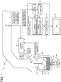
- FIG. 1 is a schematic diagram illustrating the configuration of the molten metal component estimation device as an embodiment of the present invention.
- a molten metal component estimation device 1 as an embodiment of the present invention is a device that estimates component concentrations of a molten metal 101 and a slag 103 being processed in a refining facility 2 of a steel industry.
- the refining facility 2 includes a converter 100, a lance 102, and a duct 104.
- the lance 102 is disposed above the molten metal 101 in the converter 100.
- High-pressure oxygen top-blown oxygen
- Impurities in the molten metal 101 are oxidized by the high-pressure oxygen, and is taken into the slag 103 (blowing process).
- the duct 104 for guiding exhaust gas is provided above the converter 100.
- An exhaust gas detector 105 is disposed in the duct 104.
- the exhaust gas detector 105 detects a flow rate of the exhaust gas discharged in association with the blowing process and components (for example, CO, CO 2 , O 2 , N 2 , H 2 O, and Ar) in the exhaust gas.
- the exhaust gas detector 105 measures the flow rate of the exhaust gas in the duct 104 based on, for example, differential pressure between before and after a Venturi tube provided in the duct 104.
- the exhaust gas detector 105 measures each of the component concentrations [%] of the exhaust gas.
- the flow rate and the component concentrations of the exhaust gas are measured, for example, at intervals of several seconds. Signals representing the detection results of the exhaust gas detector 105 are transmitted to a control terminal 10.
- An agitation gas (bottom-blown gas) is blown into the molten metal 101 in the converter 100 through vent holes 107 formed at the bottom of the converter 100.
- the agitation gas is an inert gas, such as Ar.
- the blown-in agitation gas agitates the molten metal 101 to promote a reaction between the high-pressure oxygen and the molten metal 101.
- a flow meter 108 measures the flow rate of the agitation gas blown into the converter 100.
- the temperature and the component concentrations of the molten metal 101 are analyzed immediately before the blowing process starts and after the blowing process.
- the temperature and the component concentrations of the molten metal 101 are measured once or a plurality of times during the blowing process, and, for example, a supply amount (oxygen feed amount) and a rate (oxygen feed rate) of the high-pressure oxygen and the flow rate of the agitation gas (agitation gas flow rate) are determined based on the measured temperature and component concentration.
- a blowing process control system to which the molten metal component estimation device 1 is applied includes the control terminal 10, the molten metal component estimation device 1, and a display device 20 as main components.
- the control terminal 10 is constituted by an information processing device, such as a personal computer or a workstation, and controls the oxygen feed amount, the oxygen feed rate, and the agitation gas flow rate so as to keep each of the component concentrations of the molten metal 101 within a desired range, and collects data of actual values of the oxygen feed amount, the oxygen feed rate, and the agitation gas flow rate.
- the molten metal component estimation device 1 is constituted by an information processing device, such as a personal computer or a workstation.
- the molten metal component estimation device 1 includes an input device 11, a model database (model DB) 12, an arithmetic processor 13, and an output device 14.
- the input device 11 is an input interface that receives various measurement results and result information regarding the refining facility 2.
- the input device 11 includes, for example, a keyboard, a mouse pointer, a pointing device, a data receiving device, and a graphical user interface (GUI).
- GUI graphical user interface
- the input device 11 receives, for example, the result data and parameter setting values from the outside, and writes the received information to the model DB 12, and transmits it to the arithmetic processor 13.
- the input device 11 receives the measurement results regarding the temperature and the component concentrations of the molten metal 101 obtained at least either one of before the start and during the blowing process in the refining facility 2.
- the measurement results regarding the temperature and the component concentrations are supplied to the input device 11 through, for example, manual input by an operator or reading input from a recording medium.
- the input device 11 receives the result information from the control terminal 10.
- the result information includes, for example, the information on the flow rate and the component concentrations of the exhaust gas measured by the exhaust gas detector 105, information on an optical characteristic at a furnace throat of the converter 100 (furnace throat spectral results and furnace throat optical characteristic information) measured by a spectrometer 106, the information on the oxygen feed amount and the oxygen feed rate, the information on the agitation gas flow rate, information on charge amounts of raw materials (main raw material and auxiliary raw materials), and the temperature information on the molten metal 101.
- the model DB 12 is a storage device that stores information on model expressions and parameters (model parameters) regarding a blowing process reaction in the refining facility 2.
- the model expressions include at least a decarburization model expression representing a relation between a carbon concentration in the molten metal 101 and the oxygen efficiency in decarburization during the blowing process.
- the oxygen efficiency in decarburization refers to an amount of carbon removed from the molten metal 101 relative to a unit amount of oxygen blown into the converter 100.
- the model DB 12 also stores various types of information received by the input device 11 and calculation/analysis results included in blowing process results calculated by the arithmetic processor 13.
- the arithmetic processor 13 is an arithmetic processing device, such as a central processing unit (CPU), and controls overall operations of the molten metal component estimation device 1.
- the arithmetic processor 13 has functions as a model determination unit 13a and a model calculation unit 13b.
- the arithmetic processor 13 executes computer programs to implement the model determination unit 13a and the model calculation unit 13b.
- the arithmetic processor 13 executes a computer program for the model determination unit 13a to serve as the model determination unit 13a, and executes a computer program for the model calculation unit 13b to serve as the model calculation unit 13b.
- the arithmetic processor 13 may include dedicated arithmetic devices or arithmetic circuits that serve as the model determination unit 13a and the model calculation unit 13b.
- the molten metal component estimation device 1 having such a configuration executes a molten metal component estimation process described below to accurately estimate the component concentrations of the molten metal 101 and the slag 103, particularly at the final stage of the blowing process.
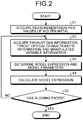
- the following describes, with reference to a flowchart illustrated in FIG. 2 , the operations of the molten metal component estimation device 1 when performing the molten metal component estimation process.
- FIG. 2 is the flowchart illustrating the flow of the molten metal component estimation process as an embodiment of the present invention.
- the flowchart illustrated in FIG. 2 starts at the time when the blowing process has started, and the molten metal component estimation process proceeds to a process at Step S1.
- the arithmetic processor 13 acquires the measurement/analysis values of the molten metal 101. Specifically, the arithmetic processor 13 acquires the measurement/analysis results obtained by the temperature measurement and the component analysis on a sample of the molten metal 101. Thus, the process at Step S1 is completed, and the molten metal component estimation process proceeds to a process at Step S2.
- the arithmetic processor 13 acquires the exhaust gas measurement/analysis information (exhaust gas information), the furnace throat optical characteristic information, and manipulated variable information from the control terminal 10.
- the exhaust gas information, the furnace throat optical characteristic information, and the manipulated variable information are collected at regular intervals. If a large time-lag is present between the time of acquisition of the manipulated variable information and the time of acquisition of the exhaust gas information, the time-lag is taken into account (the exhaust gas information is accelerated by the time-lag) to create the data.
- the measurement values and the analysis values include large amounts of noise, the measurement values and the analysis values may be replaced with values after being subjected to smoothing processing, such as moving average calculation.
- errors included in the measurement value of the exhaust gas flow rate and the analysis values of CO and CO 2 are preferably corrected.
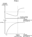
- the model determination unit 13a determines a model expression and model parameters to be used in the calculation by the model calculation unit 13b from among the model expressions and the model parameters stored in the model DB 12 based on the furnace throat optical characteristic information acquired in the process at Step S2. Specifically, a waveband of wavelength from 550 nm to 650 nm is selected from a waveband (spectrum) of light emitted in association with a decarburization reaction resulting from an iron oxide reduction reaction in the slag as represented by the following Reaction Equation (1), and the maximum value of the emission intensity in the selected waveband is detected as the optical characteristic at the furnace throat of the converter 100. It is known that when the carbon concentration in the molten metal reaches the vicinity of a critical carbon concentration, the efficiency of the decarburization reaction represented by the following Reaction Equation (1) decreases and the emission intensity also decreases.
- Reaction Equation (1) the efficiency of the decarburization reaction represented by the following Reaction Equation (1) decreases and the emission intensity also decreases.
- the model determination unit 13a calculates a change rate of the maximum value of the emission intensity (emission intensity change rate), and detects a time when the emission intensity change rate shifts from a positive value to a negative value as a time when the carbon concentration in the molten metal reaches the critical carbon concentration. In a region where the carbon concentration in the molten metal is higher than the critical carbon concentration, the model determination unit 13a selects a mass input-output calculation expression based on the exhaust gas information and the manipulated variable information or a model expression, such as a physical reaction model calculation expression, and model parameters from the model DB 12.
- the model determination unit 13a selects the decarburization model expression and model parameters thereof from the model DB 12.
- the form of the model expression selected from the model DB 12 does not matter.
- the method of switching the model expression may be, for example, a method of changing the model parameters so as to change the degree of contribution of the decarburization model expression to the model calculation.
- the model calculation unit 13b uses the model expression and the model parameters determined (selected) in the process at Step S3 to calculate the component concentrations of the molten metal 101 including the carbon concentration in the molten metal, and outputs the information on the calculated component concentrations of the molten metal 101 to the output device 14.
- Patent Literature 2 describes details of a method of calculating the component concentrations of the molten metal 101.
- the arithmetic processor 13 determines whether the blowing process has been completed. If the result of the determination indicates that the blowing process has been completed (Yes at Step S5), the arithmetic processor 13 ends the series of molten metal component estimation process. If, instead, the blowing process has not ended (No at Step S5), the arithmetic processor 13 returns the molten metal component estimation process to the process at Step S2.
- the model determination unit 13a estimates the carbon concentrations of the molten metal 101 based on the furnace throat optical characteristic information, and based on the estimation results, determines the model expression and the model parameters to be used by the model calculation unit 13b. More in detail, the model determination unit 13a detects the time when the carbon concentration of the molten metal 101 has reached the critical carbon concentration based on the furnace throat optical characteristic information, and switches the model expression and the model parameters used by the model calculation unit 13b to the model expression and the model parameters based on the relation between the carbon concentration of the molten metal and the oxygen efficiency in decarburization at the time when the carbon concentration in the molten metal 101 has reached the critical carbon concentration. Through this process, the carbon concentration of the molten metal 101 can be accurately estimated, particularly at the final stage of the blowing process.
- the present invention can provide a molten metal component estimation device and a method of estimating molten metal component capable of accurately estimating the carbon concentration in the molten metal, particularly at the final stage of the blowing process.
Landscapes
- Engineering & Computer Science (AREA)
- Chemical & Material Sciences (AREA)
- Manufacturing & Machinery (AREA)
- Organic Chemistry (AREA)
- Metallurgy (AREA)
- Materials Engineering (AREA)
- Physics & Mathematics (AREA)
- General Physics & Mathematics (AREA)
- Life Sciences & Earth Sciences (AREA)
- Theoretical Computer Science (AREA)
- Health & Medical Sciences (AREA)
- Medicinal Chemistry (AREA)
- Pathology (AREA)
- Analytical Chemistry (AREA)
- Biochemistry (AREA)
- Food Science & Technology (AREA)
- Immunology (AREA)
- Computer Hardware Design (AREA)
- Evolutionary Computation (AREA)
- Geometry (AREA)
- General Engineering & Computer Science (AREA)
- General Health & Medical Sciences (AREA)
- Carbon Steel Or Casting Steel Manufacturing (AREA)
Abstract
Description
- The present invention relates to a molten metal component estimation device that estimates component concentrations of molten metal and slag in a refining facility of a steel industry, a method of estimating molten metal component, and a method of manufacturing a molten metal.
- At ironworks, component concentrations and temperature of a hot metal tapped out of a blast furnace are adjusted in refining facilities, such as pretreatment facilities, converters, and secondary refining facilities. The converter process, among others, is a process of blowing oxygen into the converter to remove impurities from the molten metal and raise temperature thereof, and plays a very important role in terms of, for example, quality control of steel and rationalization of refining cost. In the converter process, to match the carbon concentration in the molten metal with a target carbon concentration in the molten metal at the time when the oxygen blowing is stopped, a model expression representing a relation between the oxygen efficiency in decarburization and the carbon concentration in the molten metal is generally used to control the oxygen feed amount or estimate the carbon concentration in the molten metal at the final stage of the blowing process. The oxygen efficiency in decarburization starts decreasing at the carbon concentration in the molten metal of around 0.4% (critical carbon concentration). Therefore, to obtain high calculation accuracy, it is important to perform the calculation of the model expression or switch the model expression at the time when the carbon concentration in the molten metal reaches the critical carbon concentration. Hereinafter, unless otherwise noted, the symbol % represents mass%, and various flow rates are represented in basic units of flow rate.
- Patent Literature 1 describes a method of determining timing of sub-lance measurement taking into account a time required for dynamic control and a flow rate of the blown oxygen, in static control to determine the timing of the sub-lance measurement by using, for example, a model expression based on material input-output calculation before starting the blowing process, and in the dynamic control to determine the amount of the oxygen required to be blown until the carbon concentration in the molten metal reaches the target carbon concentration in the molten metal based on the carbon concentration in the molten metal obtained by the sub-lance measurement and using the model expression representing the relation between the carbon concentration in the molten metal and the oxygen efficiency in decarburization.
-
- Patent Literature 1: Japanese Patent No.
4677955 - Patent Literature 2: Japanese Patent Application Laid-open No.
2017-115216 - In the method described in Patent Literature 1, however, the timing of the sub-lance measurement is determined based on the static model. Therefore, according to the method described in Patent Literature 1, if an error is generated in the static model calculation by, for example, a measurement error in component concentrations of the molten metal or unknown disturbances during the blowing process, the sub-lance measurement may not be performed at the target carbon concentration in the molten metal, and a sufficient time may not be ensured for the dynamic control. If, in order to ensure the time for the dynamic control, the dynamic control is performed from a state where the carbon concentration in the molten metal is higher than the critical carbon concentration, the accuracy of the dynamic control may decrease because the oxygen efficiency in decarburization does not depend on the carbon concentration in the molten metal and is affected by decarburization due to iron oxide reduction in the slag, in the region where the carbon concentration in the molten metal is higher than the critical carbon concentration.
- The present invention has been made in view of the above problems, and an object of the present invention is to provide a molten metal component estimation device and a method of estimating molten metal component capable of accurately estimating the carbon concentration in the molten metal, particularly at the final stage of the blowing process. It is another object of the present invention to provide a method of manufacturing a molten metal capable of manufacturing the molten metal having desired component concentrations at high yield.
- To solve the problem and achieve the object, a molten metal component estimation device according to the present invention includes: an input device configured to receive measurement information about a refining facility including measurement results regarding an optical characteristic at a furnace throat in the refining facility during a blowing process; a model database configured to store model expressions and model parameters, regarding a blowing process reaction, including a model expression and model parameters representing a relation between the oxygen efficiency in decarburization and a carbon concentration in a molten metal in the refining facility; a model calculation unit configured to estimate component concentrations of the molten metal including the carbon concentration in the molten metal by using the measurement information, the model expressions and the model parameters; and a model determination unit configured to: estimate the carbon concentration in the molten metal based on the measurement results; and determine the model expression and the model parameters to be used by the model calculation unit, based on the estimation result.
- Moreover, in the molten metal component estimation device according to the present invention, the measurement results include an intensity change rate of a spectrum resulting from an iron oxide reduction reaction in a slag.
- Moreover, a method of estimating molten metal component according to the present invention includes: a model calculation step of estimating component concentrations of a molten metal including a carbon concentration in the molten metal by using: measurement information about a refining facility including measurement results regarding an optical characteristic at a furnace throat in the refining facility during a blowing process; and model expressions and model parameters regarding a blowing process reaction including a model expression and model parameters representing a relation between the oxygen efficiency in decarburization and a carbon concentration in the molten metal in the refining facility; and a model determination step of: estimating the carbon concentration in the molten metal based on the measurement results; and determining the model expression and the model parameters to be used at the model calculation step based on the estimation result.
- Moreover, in the method of estimating molten metal component according to the present invention, the measurement results include an intensity change rate of a spectrum resulting from an iron oxide reduction reaction in a slag.
- Moreover, a method of manufacturing a molten metal according to the present invention includes: a step of adjusting a component concentration of a molten metal within a desired range based on estimated component concentration of the molten metal that is estimated using the method of estimating molten metal component according to the present invention.
- A molten metal component estimation device and a method of estimating molten metal component according to the present invention are capable of accurately estimating the carbon concentration in the molten metal, particularly at the final stage of the blowing process. A method of manufacturing a molten metal according to the present invention is capable of manufacturing the molten metal having a desired component concentration at high yield. Brief Description of Drawings
-
FIG. 1 is a schematic diagram illustrating a configuration of a molten metal component estimation device as an embodiment of the present invention. -
FIG. 2 is a flowchart illustrating a flow of a molten metal component estimation process as an embodiment of the present invention. -
FIG. 3 depicts diagrams illustrating examples of a relation between a carbon concentration in a molten metal and an emission intensity change rate and a relation between the carbon concentration in the molten metal and the oxygen efficiency in decarburization. - The following describes in detail a molten metal component estimation device and operations thereof as an embodiment of the present invention with reference to the drawings.
- First, a configuration of the molten metal component estimation device as an embodiment of the present invention will be described with reference to
FIG. 1 . -
FIG. 1 is a schematic diagram illustrating the configuration of the molten metal component estimation device as an embodiment of the present invention. As illustrated inFIG. 1 , a molten metal component estimation device 1 as an embodiment of the present invention is a device that estimates component concentrations of amolten metal 101 and aslag 103 being processed in arefining facility 2 of a steel industry. Therefining facility 2 includes aconverter 100, alance 102, and aduct 104. Thelance 102 is disposed above themolten metal 101 in theconverter 100. High-pressure oxygen (top-blown oxygen) is ejected from a distal end of thelance 102 toward themolten metal 101 below. Impurities in themolten metal 101 are oxidized by the high-pressure oxygen, and is taken into the slag 103 (blowing process). Theduct 104 for guiding exhaust gas is provided above theconverter 100. - An
exhaust gas detector 105 is disposed in theduct 104. Theexhaust gas detector 105 detects a flow rate of the exhaust gas discharged in association with the blowing process and components (for example, CO, CO2, O2, N2, H2O, and Ar) in the exhaust gas. Theexhaust gas detector 105 measures the flow rate of the exhaust gas in theduct 104 based on, for example, differential pressure between before and after a Venturi tube provided in theduct 104. Theexhaust gas detector 105 measures each of the component concentrations [%] of the exhaust gas. The flow rate and the component concentrations of the exhaust gas are measured, for example, at intervals of several seconds. Signals representing the detection results of theexhaust gas detector 105 are transmitted to acontrol terminal 10. - An agitation gas (bottom-blown gas) is blown into the
molten metal 101 in theconverter 100 throughvent holes 107 formed at the bottom of theconverter 100. The agitation gas is an inert gas, such as Ar. The blown-in agitation gas agitates themolten metal 101 to promote a reaction between the high-pressure oxygen and themolten metal 101. Aflow meter 108 measures the flow rate of the agitation gas blown into theconverter 100. The temperature and the component concentrations of themolten metal 101 are analyzed immediately before the blowing process starts and after the blowing process. The temperature and the component concentrations of themolten metal 101 are measured once or a plurality of times during the blowing process, and, for example, a supply amount (oxygen feed amount) and a rate (oxygen feed rate) of the high-pressure oxygen and the flow rate of the agitation gas (agitation gas flow rate) are determined based on the measured temperature and component concentration. - A blowing process control system to which the molten metal component estimation device 1 is applied includes the
control terminal 10, the molten metal component estimation device 1, and adisplay device 20 as main components. Thecontrol terminal 10 is constituted by an information processing device, such as a personal computer or a workstation, and controls the oxygen feed amount, the oxygen feed rate, and the agitation gas flow rate so as to keep each of the component concentrations of themolten metal 101 within a desired range, and collects data of actual values of the oxygen feed amount, the oxygen feed rate, and the agitation gas flow rate. - The molten metal component estimation device 1 is constituted by an information processing device, such as a personal computer or a workstation. The molten metal component estimation device 1 includes an
input device 11, a model database (model DB) 12, anarithmetic processor 13, and anoutput device 14. - The
input device 11 is an input interface that receives various measurement results and result information regarding therefining facility 2. Theinput device 11 includes, for example, a keyboard, a mouse pointer, a pointing device, a data receiving device, and a graphical user interface (GUI). Theinput device 11 receives, for example, the result data and parameter setting values from the outside, and writes the received information to themodel DB 12, and transmits it to thearithmetic processor 13. Theinput device 11 receives the measurement results regarding the temperature and the component concentrations of themolten metal 101 obtained at least either one of before the start and during the blowing process in therefining facility 2. The measurement results regarding the temperature and the component concentrations are supplied to theinput device 11 through, for example, manual input by an operator or reading input from a recording medium. Theinput device 11 receives the result information from thecontrol terminal 10. The result information includes, for example, the information on the flow rate and the component concentrations of the exhaust gas measured by theexhaust gas detector 105, information on an optical characteristic at a furnace throat of the converter 100 (furnace throat spectral results and furnace throat optical characteristic information) measured by aspectrometer 106, the information on the oxygen feed amount and the oxygen feed rate, the information on the agitation gas flow rate, information on charge amounts of raw materials (main raw material and auxiliary raw materials), and the temperature information on themolten metal 101. - The
model DB 12 is a storage device that stores information on model expressions and parameters (model parameters) regarding a blowing process reaction in therefining facility 2. The model expressions include at least a decarburization model expression representing a relation between a carbon concentration in themolten metal 101 and the oxygen efficiency in decarburization during the blowing process. The oxygen efficiency in decarburization refers to an amount of carbon removed from themolten metal 101 relative to a unit amount of oxygen blown into theconverter 100. Themodel DB 12 also stores various types of information received by theinput device 11 and calculation/analysis results included in blowing process results calculated by thearithmetic processor 13. - The
arithmetic processor 13 is an arithmetic processing device, such as a central processing unit (CPU), and controls overall operations of the molten metal component estimation device 1. Thearithmetic processor 13 has functions as amodel determination unit 13a and amodel calculation unit 13b. For example, thearithmetic processor 13 executes computer programs to implement themodel determination unit 13a and themodel calculation unit 13b. Thearithmetic processor 13 executes a computer program for themodel determination unit 13a to serve as themodel determination unit 13a, and executes a computer program for themodel calculation unit 13b to serve as themodel calculation unit 13b. Thearithmetic processor 13 may include dedicated arithmetic devices or arithmetic circuits that serve as themodel determination unit 13a and themodel calculation unit 13b. - The molten metal component estimation device 1 having such a configuration executes a molten metal component estimation process described below to accurately estimate the component concentrations of the
molten metal 101 and theslag 103, particularly at the final stage of the blowing process. The following describes, with reference to a flowchart illustrated inFIG. 2 , the operations of the molten metal component estimation device 1 when performing the molten metal component estimation process. -
FIG. 2 is the flowchart illustrating the flow of the molten metal component estimation process as an embodiment of the present invention. The flowchart illustrated inFIG. 2 starts at the time when the blowing process has started, and the molten metal component estimation process proceeds to a process at Step S1. - In the process at Step S1, the
arithmetic processor 13 acquires the measurement/analysis values of themolten metal 101. Specifically, thearithmetic processor 13 acquires the measurement/analysis results obtained by the temperature measurement and the component analysis on a sample of themolten metal 101. Thus, the process at Step S1 is completed, and the molten metal component estimation process proceeds to a process at Step S2. - In the process at Step S2, the
arithmetic processor 13 acquires the exhaust gas measurement/analysis information (exhaust gas information), the furnace throat optical characteristic information, and manipulated variable information from thecontrol terminal 10. In a normal converter blowing operation, the exhaust gas information, the furnace throat optical characteristic information, and the manipulated variable information are collected at regular intervals. If a large time-lag is present between the time of acquisition of the manipulated variable information and the time of acquisition of the exhaust gas information, the time-lag is taken into account (the exhaust gas information is accelerated by the time-lag) to create the data. If the measurement values and the analysis values include large amounts of noise, the measurement values and the analysis values may be replaced with values after being subjected to smoothing processing, such as moving average calculation. Moreover, errors included in the measurement value of the exhaust gas flow rate and the analysis values of CO and CO2 are preferably corrected. Thus, the process at Step S2 is completed, and the molten metal component estimation process proceeds to a process at Step S3. - In the process at Step S3, the
model determination unit 13a determines a model expression and model parameters to be used in the calculation by themodel calculation unit 13b from among the model expressions and the model parameters stored in themodel DB 12 based on the furnace throat optical characteristic information acquired in the process at Step S2. Specifically, a waveband of wavelength from 550 nm to 650 nm is selected from a waveband (spectrum) of light emitted in association with a decarburization reaction resulting from an iron oxide reduction reaction in the slag as represented by the following Reaction Equation (1), and the maximum value of the emission intensity in the selected waveband is detected as the optical characteristic at the furnace throat of theconverter 100. It is known that when the carbon concentration in the molten metal reaches the vicinity of a critical carbon concentration, the efficiency of the decarburization reaction represented by the following Reaction Equation (1) decreases and the emission intensity also decreases.
FeO + C → Fe + CO (1)
- Accordingly, as illustrated in
FIG. 3(a) , themodel determination unit 13a calculates a change rate of the maximum value of the emission intensity (emission intensity change rate), and detects a time when the emission intensity change rate shifts from a positive value to a negative value as a time when the carbon concentration in the molten metal reaches the critical carbon concentration. In a region where the carbon concentration in the molten metal is higher than the critical carbon concentration, themodel determination unit 13a selects a mass input-output calculation expression based on the exhaust gas information and the manipulated variable information or a model expression, such as a physical reaction model calculation expression, and model parameters from themodel DB 12. After the time when the carbon concentration in the molten metal reaches the critical carbon concentration, the carbon concentration in the molten metal enters a region where the oxygen efficiency in decarburization depends on the carbon concentration in the molten metal as illustrated inFIG. 3(b) . Accordingly, themodel determination unit 13a selects the decarburization model expression and model parameters thereof from themodel DB 12. In the present invention, the form of the model expression selected from themodel DB 12 does not matter. The method of switching the model expression may be, for example, a method of changing the model parameters so as to change the degree of contribution of the decarburization model expression to the model calculation. Thus, the process at Step S3 is completed, and the molten metal component estimation process proceeds to a process at Step S4. - In the process at Step S4, the
model calculation unit 13b uses the model expression and the model parameters determined (selected) in the process at Step S3 to calculate the component concentrations of themolten metal 101 including the carbon concentration in the molten metal, and outputs the information on the calculated component concentrations of themolten metal 101 to theoutput device 14. For example,Patent Literature 2 describes details of a method of calculating the component concentrations of themolten metal 101. Thus, the process at Step S4 is completed, and the molten metal component estimation process proceeds to a process at Step S5. - In the process at Step S5, the
arithmetic processor 13 determines whether the blowing process has been completed. If the result of the determination indicates that the blowing process has been completed (Yes at Step S5), thearithmetic processor 13 ends the series of molten metal component estimation process. If, instead, the blowing process has not ended (No at Step S5), thearithmetic processor 13 returns the molten metal component estimation process to the process at Step S2. - As is clear from the above description, in the molten metal component estimation process as an embodiment of the present invention, the
model determination unit 13a estimates the carbon concentrations of themolten metal 101 based on the furnace throat optical characteristic information, and based on the estimation results, determines the model expression and the model parameters to be used by themodel calculation unit 13b. More in detail, themodel determination unit 13a detects the time when the carbon concentration of themolten metal 101 has reached the critical carbon concentration based on the furnace throat optical characteristic information, and switches the model expression and the model parameters used by themodel calculation unit 13b to the model expression and the model parameters based on the relation between the carbon concentration of the molten metal and the oxygen efficiency in decarburization at the time when the carbon concentration in themolten metal 101 has reached the critical carbon concentration. Through this process, the carbon concentration of themolten metal 101 can be accurately estimated, particularly at the final stage of the blowing process. - While the embodiment to which the invention made by the present inventors is applied has been described, the present invention is not limited to the description and the drawings constituting a part of the disclosure of the present invention by way of the present embodiment. The model switching in the estimation calculation of the carbon concentration in the molten metal has been described in the present embodiment. However, for example, when the control is performed using a static model and a dynamic model as described in the method of Patent Literature 1, dynamic model control can be performed at appropriate timing by acquiring the dynamic model from the
model DB 12 based on the furnace throat optical characteristic measurement information. Thus, other embodiments, examples, operational techniques, and the like made by those skilled in the art based on the present embodiment are all included in the scope of the present invention. - The present invention can provide a molten metal component estimation device and a method of estimating molten metal component capable of accurately estimating the carbon concentration in the molten metal, particularly at the final stage of the blowing process.
-
- 1
- Molten metal component estimation device
- 2
- Refining facility
- 10
- Control terminal
- 11
- Input device
- 12
- Model database (model DB)
- 13
- Arithmetic processor
- 13a
- Model determination unit
- 13b
- Model calculation unit
- 14
- Output device
- 20
- Display device
- 100
- Converter
- 101
- Molten metal
- 102
- Lance
- 103
- Slag
- 104
- Duct
- 105
- Exhaust gas detector
- 106
- Spectrometer
- 107
- Vent holes
- 108
- Flow meter
Claims (5)
- A molten metal component estimation device comprising:an input device configured to receive measurement information about a refining facility including measurement results regarding an optical characteristic at a furnace throat in the refining facility during a blowing process;a model database configured to store model expressions and model parameters, regarding a blowing process reaction, including a model expression and model parameters representing a relation between the oxygen efficiency in decarburization and a carbon concentration in a molten metal in the refining facility;a model calculation unit configured to estimate component concentrations of the molten metal including the carbon concentration in the molten metal by using the measurement information, the model expressions and the model parameters; anda model determination unit configured to:estimate the carbon concentration in the molten metal based on the measurement results; anddetermine the model expression and the model parameters to be used by the model calculation unit, based on the estimation result.
- The molten metal component estimation device according to claim 1, wherein the measurement results include an intensity change rate of a spectrum resulting from an iron oxide reduction reaction in a slag.
- A method of estimating molten metal component, comprising:a model calculation step of estimating component concentrations of a molten metal including a carbon concentration in the molten metal by using:measurement information about a refining facility including measurement results regarding an optical characteristic at a furnace throat in the refining facility during a blowing process; andmodel expressions and model parameters regarding a blowing process reaction including a model expression and model parameters representing a relation between the oxygen efficiency in decarburization and a carbon concentration in the molten metal in the refining facility; anda model determination step of:estimating the carbon concentration in the molten metal based on the measurement results; anddetermining the model expression and the model parameters to be used at the model calculation step based on the estimation result.
- The method of estimating molten metal component according to claim 3, wherein the measurement results include an intensity change rate of a spectrum resulting from an iron oxide reduction reaction in a slag.
- A method of manufacturing a molten metal, comprising a step of adjusting a component concentration of a molten metal within a desired range based on estimated component concentration of the molten metal that is estimated using the method of estimating molten metal component according to claim 3 or 4.
Applications Claiming Priority (2)
| Application Number | Priority Date | Filing Date | Title |
|---|---|---|---|
| JP2018092754 | 2018-05-14 | ||
| PCT/JP2019/014829 WO2019220800A1 (en) | 2018-05-14 | 2019-04-03 | Melt component estimation device, melt component estimation method, and method for producing melt |
Publications (3)
| Publication Number | Publication Date |
|---|---|
| EP3795702A1 true EP3795702A1 (en) | 2021-03-24 |
| EP3795702A4 EP3795702A4 (en) | 2021-12-29 |
| EP3795702B1 EP3795702B1 (en) | 2024-03-20 |
Family
ID=68540191
Family Applications (1)
| Application Number | Title | Priority Date | Filing Date |
|---|---|---|---|
| EP19804356.4A Active EP3795702B1 (en) | 2018-05-14 | 2019-04-03 | Melt component estimation device, melt component estimation method, and method for producing melt |
Country Status (8)
| Country | Link |
|---|---|
| US (1) | US11966669B2 (en) |
| EP (1) | EP3795702B1 (en) |
| JP (1) | JP6825711B2 (en) |
| KR (1) | KR102437794B1 (en) |
| CN (1) | CN112154218B (en) |
| RU (1) | RU2766093C1 (en) |
| TW (1) | TWI700374B (en) |
| WO (1) | WO2019220800A1 (en) |
Families Citing this family (5)
| Publication number | Priority date | Publication date | Assignee | Title |
|---|---|---|---|---|
| CN111763803B (en) * | 2020-08-18 | 2021-12-14 | 长春工业大学 | Molten iron temperature control method in argon oxygen refined iron alloy production process |
| JP7088439B1 (en) | 2020-12-11 | 2022-06-21 | Jfeスチール株式会社 | Operation method of converter and blowing control system of converter |
| EP4400607A4 (en) * | 2021-11-29 | 2025-01-15 | JFE Steel Corporation | INTRA-FURNACE STATE INFERENCE DEVICE, INTRA-FURNACE STATE INFERENCE METHOD, AND MOLTEN STEEL MANUFACTURING METHOD |
| LU502564B1 (en) * | 2022-07-25 | 2024-01-25 | Wurth Paul Sa | Estimating element content in molten material at openings of metallurgical vessels |
| US20250388987A1 (en) * | 2024-06-20 | 2025-12-25 | Victor H. Hernandez Avila | Methods for Improved Carbon Endpoint Determination |
Family Cites Families (17)
| Publication number | Priority date | Publication date | Assignee | Title |
|---|---|---|---|---|
| JPS6267430A (en) | 1985-09-20 | 1987-03-27 | Nippon Steel Corp | Spectral analysis of components in molten iron |
| JPS6318012A (en) * | 1986-07-09 | 1988-01-25 | Nippon Kokan Kk <Nkk> | Method for controlling flow rate of oxygen for refining for metallurgical refining furnace |
| JPH04308019A (en) * | 1991-04-03 | 1992-10-30 | Sumitomo Metal Ind Ltd | Method for controlling end point of blowing in converter |
| US5984998A (en) * | 1997-11-14 | 1999-11-16 | American Iron And Steel Institute | Method and apparatus for off-gas composition sensing |
| JP3861480B2 (en) | 1998-11-12 | 2006-12-20 | Jfeスチール株式会社 | Slag analysis method and apparatus |
| RU2180951C1 (en) | 2001-04-28 | 2002-03-27 | Пономаренко Дмитрий Александрович | Method for controlling metallurgical melting process |
| JP4677955B2 (en) | 2006-06-08 | 2011-04-27 | 住友金属工業株式会社 | Converter blowing control method, converter blowing control device, and computer program |
| US20110045422A1 (en) * | 2009-08-21 | 2011-02-24 | Alstom Technology Ltd | Optical flue gas monitor and control |
| DE102009060258A1 (en) | 2009-12-23 | 2011-06-30 | SMS Siemag Aktiengesellschaft, 40237 | Control of the converter process by exhaust signals |
| CN101825567A (en) | 2010-04-02 | 2010-09-08 | 南开大学 | Screening method for near infrared spectrum wavelength and Raman spectrum wavelength |
| CN102206727A (en) | 2011-05-31 | 2011-10-05 | 湖南镭目科技有限公司 | Converter steelmaking endpoint determination method and system, control method and control system |
| CN104531936B (en) * | 2014-12-01 | 2016-08-31 | 南华大学 | Converter molten steel carbon content On-line Measuring Method based on Flame Image Characteristics |
| CN106153550A (en) * | 2015-04-10 | 2016-11-23 | 南京理工大学 | Converter steel-smelting molten steel carbon content based on SVM online Real-time and Dynamic Detection method |
| JP2017008349A (en) * | 2015-06-18 | 2017-01-12 | Jfeスチール株式会社 | Molten state estimation apparatus and molten state estimation method |
| CN205024254U (en) | 2015-10-16 | 2016-02-10 | 唐山钢铁集团有限责任公司 | Converter mouth flame image collection system |
| JP6376200B2 (en) * | 2015-11-02 | 2018-08-22 | Jfeスチール株式会社 | Molten state estimation device, molten state estimation method, and molten metal manufacturing method |
| JP6414045B2 (en) | 2015-12-25 | 2018-10-31 | Jfeスチール株式会社 | Molten component estimation device and molten component estimation method |
-
2019
- 2019-04-03 US US17/054,968 patent/US11966669B2/en active Active
- 2019-04-03 RU RU2020140778A patent/RU2766093C1/en active
- 2019-04-03 JP JP2019537859A patent/JP6825711B2/en active Active
- 2019-04-03 WO PCT/JP2019/014829 patent/WO2019220800A1/en not_active Ceased
- 2019-04-03 KR KR1020207034872A patent/KR102437794B1/en active Active
- 2019-04-03 CN CN201980031713.5A patent/CN112154218B/en active Active
- 2019-04-03 EP EP19804356.4A patent/EP3795702B1/en active Active
- 2019-04-18 TW TW108113511A patent/TWI700374B/en active
Also Published As
| Publication number | Publication date |
|---|---|
| JP6825711B2 (en) | 2021-02-03 |
| US20210216680A1 (en) | 2021-07-15 |
| EP3795702B1 (en) | 2024-03-20 |
| CN112154218B (en) | 2022-09-27 |
| KR20210003917A (en) | 2021-01-12 |
| JPWO2019220800A1 (en) | 2020-05-28 |
| WO2019220800A1 (en) | 2019-11-21 |
| KR102437794B1 (en) | 2022-08-29 |
| TW201947039A (en) | 2019-12-16 |
| CN112154218A (en) | 2020-12-29 |
| TWI700374B (en) | 2020-08-01 |
| EP3795702A4 (en) | 2021-12-29 |
| BR112020022857A2 (en) | 2021-02-23 |
| US11966669B2 (en) | 2024-04-23 |
| RU2766093C1 (en) | 2022-02-07 |
Similar Documents
| Publication | Publication Date | Title |
|---|---|---|
| US11966669B2 (en) | Molten metal component estimation device, method of estimating molten metal component, and method of manufacturing molten metal | |
| EP3770279B1 (en) | Molten metal component estimation device, molten metal component estimation method, and molten metal production method | |
| JP2017008349A (en) | Molten state estimation apparatus and molten state estimation method | |
| RU2539501C2 (en) | Converter process control by exit gas signals | |
| JP6579136B2 (en) | Refining process state estimation device, refining process state estimation method, and molten metal manufacturing method | |
| JP6414045B2 (en) | Molten component estimation device and molten component estimation method | |
| JP7156560B2 (en) | Refining process control device and refining process control method | |
| EP4400607A1 (en) | Intra-furnace state inference device, intra-furnace state inference method, and molten steel manufacturing method | |
| JP2017089001A (en) | Molten metal condition estimation device, molten metal condition estimation method, and manufacturing method of molten metal | |
| EP3943618B1 (en) | Blowing control method and blowing control apparatus for converter type dephosphorization refining furnace | |
| JP6331601B2 (en) | Blowing control method in steelmaking converter. | |
| JP6060613B2 (en) | Gas flow estimation apparatus and gas flow estimation method | |
| BR112020022857B1 (en) | CAST METAL COMPONENT ESTIMATION DEVICE, CAST METAL COMPONENT ESTIMATION METHOD AND CAST METAL FABRICATION METHOD | |
| TW201734214A (en) | Molten pig iron pre-treatment method and molten pig iron pre-treatment control device | |
| BR112021018589B1 (en) | BLOW CONTROL METHOD AND BLOW CONTROL APPARATUS FOR CONVERTER TYPE DEPHOSPHORIZATION REFINING FURNACE |
Legal Events
| Date | Code | Title | Description |
|---|---|---|---|
| STAA | Information on the status of an ep patent application or granted ep patent |
Free format text: STATUS: THE INTERNATIONAL PUBLICATION HAS BEEN MADE |
|
| PUAI | Public reference made under article 153(3) epc to a published international application that has entered the european phase |
Free format text: ORIGINAL CODE: 0009012 |
|
| STAA | Information on the status of an ep patent application or granted ep patent |
Free format text: STATUS: REQUEST FOR EXAMINATION WAS MADE |
|
| 17P | Request for examination filed |
Effective date: 20201130 |
|
| AK | Designated contracting states |
Kind code of ref document: A1 Designated state(s): AL AT BE BG CH CY CZ DE DK EE ES FI FR GB GR HR HU IE IS IT LI LT LU LV MC MK MT NL NO PL PT RO RS SE SI SK SM TR |
|
| AX | Request for extension of the european patent |
Extension state: BA ME |
|
| DAV | Request for validation of the european patent (deleted) | ||
| DAX | Request for extension of the european patent (deleted) | ||
| A4 | Supplementary search report drawn up and despatched |
Effective date: 20211126 |
|
| RIC1 | Information provided on ipc code assigned before grant |
Ipc: C21C 5/46 20060101ALI20211122BHEP Ipc: C21C 5/32 20060101ALI20211122BHEP Ipc: C21C 5/30 20060101AFI20211122BHEP |
|
| STAA | Information on the status of an ep patent application or granted ep patent |
Free format text: STATUS: EXAMINATION IS IN PROGRESS |
|
| 17Q | First examination report despatched |
Effective date: 20220915 |
|
| REG | Reference to a national code |
Ref country code: DE Ref legal event code: R079 Ipc: C21C0005320000 Ref country code: DE Ref legal event code: R079 Ref document number: 602019048699 Country of ref document: DE Free format text: PREVIOUS MAIN CLASS: C21C0005300000 Ipc: C21C0005320000 |
|
| RIC1 | Information provided on ipc code assigned before grant |
Ipc: C21C 5/30 20060101ALN20231012BHEP Ipc: C21C 5/46 20060101ALI20231012BHEP Ipc: C21C 5/32 20060101AFI20231012BHEP |
|
| GRAP | Despatch of communication of intention to grant a patent |
Free format text: ORIGINAL CODE: EPIDOSNIGR1 |
|
| STAA | Information on the status of an ep patent application or granted ep patent |
Free format text: STATUS: GRANT OF PATENT IS INTENDED |
|
| INTG | Intention to grant announced |
Effective date: 20231122 |
|
| GRAS | Grant fee paid |
Free format text: ORIGINAL CODE: EPIDOSNIGR3 |
|
| GRAA | (expected) grant |
Free format text: ORIGINAL CODE: 0009210 |
|
| STAA | Information on the status of an ep patent application or granted ep patent |
Free format text: STATUS: THE PATENT HAS BEEN GRANTED |
|
| AK | Designated contracting states |
Kind code of ref document: B1 Designated state(s): AL AT BE BG CH CY CZ DE DK EE ES FI FR GB GR HR HU IE IS IT LI LT LU LV MC MK MT NL NO PL PT RO RS SE SI SK SM TR |
|
| REG | Reference to a national code |
Ref country code: GB Ref legal event code: FG4D |
|
| REG | Reference to a national code |
Ref country code: CH Ref legal event code: EP |
|
| REG | Reference to a national code |
Ref country code: IE Ref legal event code: FG4D |
|
| REG | Reference to a national code |
Ref country code: DE Ref legal event code: R096 Ref document number: 602019048699 Country of ref document: DE |
|
| PG25 | Lapsed in a contracting state [announced via postgrant information from national office to epo] |
Ref country code: LT Free format text: LAPSE BECAUSE OF FAILURE TO SUBMIT A TRANSLATION OF THE DESCRIPTION OR TO PAY THE FEE WITHIN THE PRESCRIBED TIME-LIMIT Effective date: 20240320 |
|
| REG | Reference to a national code |
Ref country code: LT Ref legal event code: MG9D |
|
| PG25 | Lapsed in a contracting state [announced via postgrant information from national office to epo] |
Ref country code: GR Free format text: LAPSE BECAUSE OF FAILURE TO SUBMIT A TRANSLATION OF THE DESCRIPTION OR TO PAY THE FEE WITHIN THE PRESCRIBED TIME-LIMIT Effective date: 20240621 |
|
| PG25 | Lapsed in a contracting state [announced via postgrant information from national office to epo] |
Ref country code: RS Free format text: LAPSE BECAUSE OF FAILURE TO SUBMIT A TRANSLATION OF THE DESCRIPTION OR TO PAY THE FEE WITHIN THE PRESCRIBED TIME-LIMIT Effective date: 20240620 Ref country code: HR Free format text: LAPSE BECAUSE OF FAILURE TO SUBMIT A TRANSLATION OF THE DESCRIPTION OR TO PAY THE FEE WITHIN THE PRESCRIBED TIME-LIMIT Effective date: 20240320 |
|
| REG | Reference to a national code |
Ref country code: NL Ref legal event code: MP Effective date: 20240320 |
|
| PG25 | Lapsed in a contracting state [announced via postgrant information from national office to epo] |
Ref country code: RS Free format text: LAPSE BECAUSE OF FAILURE TO SUBMIT A TRANSLATION OF THE DESCRIPTION OR TO PAY THE FEE WITHIN THE PRESCRIBED TIME-LIMIT Effective date: 20240620 Ref country code: NO Free format text: LAPSE BECAUSE OF FAILURE TO SUBMIT A TRANSLATION OF THE DESCRIPTION OR TO PAY THE FEE WITHIN THE PRESCRIBED TIME-LIMIT Effective date: 20240620 Ref country code: LT Free format text: LAPSE BECAUSE OF FAILURE TO SUBMIT A TRANSLATION OF THE DESCRIPTION OR TO PAY THE FEE WITHIN THE PRESCRIBED TIME-LIMIT Effective date: 20240320 Ref country code: HR Free format text: LAPSE BECAUSE OF FAILURE TO SUBMIT A TRANSLATION OF THE DESCRIPTION OR TO PAY THE FEE WITHIN THE PRESCRIBED TIME-LIMIT Effective date: 20240320 Ref country code: GR Free format text: LAPSE BECAUSE OF FAILURE TO SUBMIT A TRANSLATION OF THE DESCRIPTION OR TO PAY THE FEE WITHIN THE PRESCRIBED TIME-LIMIT Effective date: 20240621 Ref country code: FI Free format text: LAPSE BECAUSE OF FAILURE TO SUBMIT A TRANSLATION OF THE DESCRIPTION OR TO PAY THE FEE WITHIN THE PRESCRIBED TIME-LIMIT Effective date: 20240320 Ref country code: BG Free format text: LAPSE BECAUSE OF FAILURE TO SUBMIT A TRANSLATION OF THE DESCRIPTION OR TO PAY THE FEE WITHIN THE PRESCRIBED TIME-LIMIT Effective date: 20240320 |
|
| REG | Reference to a national code |
Ref country code: AT Ref legal event code: MK05 Ref document number: 1667873 Country of ref document: AT Kind code of ref document: T Effective date: 20240320 |
|
| PG25 | Lapsed in a contracting state [announced via postgrant information from national office to epo] |
Ref country code: SE Free format text: LAPSE BECAUSE OF FAILURE TO SUBMIT A TRANSLATION OF THE DESCRIPTION OR TO PAY THE FEE WITHIN THE PRESCRIBED TIME-LIMIT Effective date: 20240320 Ref country code: LV Free format text: LAPSE BECAUSE OF FAILURE TO SUBMIT A TRANSLATION OF THE DESCRIPTION OR TO PAY THE FEE WITHIN THE PRESCRIBED TIME-LIMIT Effective date: 20240320 |
|
| PG25 | Lapsed in a contracting state [announced via postgrant information from national office to epo] |
Ref country code: NL Free format text: LAPSE BECAUSE OF FAILURE TO SUBMIT A TRANSLATION OF THE DESCRIPTION OR TO PAY THE FEE WITHIN THE PRESCRIBED TIME-LIMIT Effective date: 20240320 |
|
| PG25 | Lapsed in a contracting state [announced via postgrant information from national office to epo] |
Ref country code: NL Free format text: LAPSE BECAUSE OF FAILURE TO SUBMIT A TRANSLATION OF THE DESCRIPTION OR TO PAY THE FEE WITHIN THE PRESCRIBED TIME-LIMIT Effective date: 20240320 |
|
| PG25 | Lapsed in a contracting state [announced via postgrant information from national office to epo] |
Ref country code: IS Free format text: LAPSE BECAUSE OF FAILURE TO SUBMIT A TRANSLATION OF THE DESCRIPTION OR TO PAY THE FEE WITHIN THE PRESCRIBED TIME-LIMIT Effective date: 20240720 |
|
| PG25 | Lapsed in a contracting state [announced via postgrant information from national office to epo] |
Ref country code: PT Free format text: LAPSE BECAUSE OF FAILURE TO SUBMIT A TRANSLATION OF THE DESCRIPTION OR TO PAY THE FEE WITHIN THE PRESCRIBED TIME-LIMIT Effective date: 20240722 Ref country code: SM Free format text: LAPSE BECAUSE OF FAILURE TO SUBMIT A TRANSLATION OF THE DESCRIPTION OR TO PAY THE FEE WITHIN THE PRESCRIBED TIME-LIMIT Effective date: 20240320 |
|
| PG25 | Lapsed in a contracting state [announced via postgrant information from national office to epo] |
Ref country code: ES Free format text: LAPSE BECAUSE OF FAILURE TO SUBMIT A TRANSLATION OF THE DESCRIPTION OR TO PAY THE FEE WITHIN THE PRESCRIBED TIME-LIMIT Effective date: 20240320 |
|
| PG25 | Lapsed in a contracting state [announced via postgrant information from national office to epo] |
Ref country code: EE Free format text: LAPSE BECAUSE OF FAILURE TO SUBMIT A TRANSLATION OF THE DESCRIPTION OR TO PAY THE FEE WITHIN THE PRESCRIBED TIME-LIMIT Effective date: 20240320 Ref country code: CZ Free format text: LAPSE BECAUSE OF FAILURE TO SUBMIT A TRANSLATION OF THE DESCRIPTION OR TO PAY THE FEE WITHIN THE PRESCRIBED TIME-LIMIT Effective date: 20240320 |
|
| PG25 | Lapsed in a contracting state [announced via postgrant information from national office to epo] |
Ref country code: AT Free format text: LAPSE BECAUSE OF FAILURE TO SUBMIT A TRANSLATION OF THE DESCRIPTION OR TO PAY THE FEE WITHIN THE PRESCRIBED TIME-LIMIT Effective date: 20240320 |
|
| PG25 | Lapsed in a contracting state [announced via postgrant information from national office to epo] |
Ref country code: PL Free format text: LAPSE BECAUSE OF FAILURE TO SUBMIT A TRANSLATION OF THE DESCRIPTION OR TO PAY THE FEE WITHIN THE PRESCRIBED TIME-LIMIT Effective date: 20240320 |
|
| PG25 | Lapsed in a contracting state [announced via postgrant information from national office to epo] |
Ref country code: SK Free format text: LAPSE BECAUSE OF FAILURE TO SUBMIT A TRANSLATION OF THE DESCRIPTION OR TO PAY THE FEE WITHIN THE PRESCRIBED TIME-LIMIT Effective date: 20240320 |
|
| PG25 | Lapsed in a contracting state [announced via postgrant information from national office to epo] |
Ref country code: SM Free format text: LAPSE BECAUSE OF FAILURE TO SUBMIT A TRANSLATION OF THE DESCRIPTION OR TO PAY THE FEE WITHIN THE PRESCRIBED TIME-LIMIT Effective date: 20240320 Ref country code: SK Free format text: LAPSE BECAUSE OF FAILURE TO SUBMIT A TRANSLATION OF THE DESCRIPTION OR TO PAY THE FEE WITHIN THE PRESCRIBED TIME-LIMIT Effective date: 20240320 Ref country code: RO Free format text: LAPSE BECAUSE OF FAILURE TO SUBMIT A TRANSLATION OF THE DESCRIPTION OR TO PAY THE FEE WITHIN THE PRESCRIBED TIME-LIMIT Effective date: 20240320 Ref country code: PT Free format text: LAPSE BECAUSE OF FAILURE TO SUBMIT A TRANSLATION OF THE DESCRIPTION OR TO PAY THE FEE WITHIN THE PRESCRIBED TIME-LIMIT Effective date: 20240722 Ref country code: PL Free format text: LAPSE BECAUSE OF FAILURE TO SUBMIT A TRANSLATION OF THE DESCRIPTION OR TO PAY THE FEE WITHIN THE PRESCRIBED TIME-LIMIT Effective date: 20240320 Ref country code: IS Free format text: LAPSE BECAUSE OF FAILURE TO SUBMIT A TRANSLATION OF THE DESCRIPTION OR TO PAY THE FEE WITHIN THE PRESCRIBED TIME-LIMIT Effective date: 20240720 Ref country code: ES Free format text: LAPSE BECAUSE OF FAILURE TO SUBMIT A TRANSLATION OF THE DESCRIPTION OR TO PAY THE FEE WITHIN THE PRESCRIBED TIME-LIMIT Effective date: 20240320 Ref country code: EE Free format text: LAPSE BECAUSE OF FAILURE TO SUBMIT A TRANSLATION OF THE DESCRIPTION OR TO PAY THE FEE WITHIN THE PRESCRIBED TIME-LIMIT Effective date: 20240320 Ref country code: CZ Free format text: LAPSE BECAUSE OF FAILURE TO SUBMIT A TRANSLATION OF THE DESCRIPTION OR TO PAY THE FEE WITHIN THE PRESCRIBED TIME-LIMIT Effective date: 20240320 Ref country code: AT Free format text: LAPSE BECAUSE OF FAILURE TO SUBMIT A TRANSLATION OF THE DESCRIPTION OR TO PAY THE FEE WITHIN THE PRESCRIBED TIME-LIMIT Effective date: 20240320 |
|
| REG | Reference to a national code |
Ref country code: CH Ref legal event code: PL |
|
| PG25 | Lapsed in a contracting state [announced via postgrant information from national office to epo] |
Ref country code: IT Free format text: LAPSE BECAUSE OF FAILURE TO SUBMIT A TRANSLATION OF THE DESCRIPTION OR TO PAY THE FEE WITHIN THE PRESCRIBED TIME-LIMIT Effective date: 20240320 |
|
| PG25 | Lapsed in a contracting state [announced via postgrant information from national office to epo] |
Ref country code: LU Free format text: LAPSE BECAUSE OF NON-PAYMENT OF DUE FEES Effective date: 20240403 |
|
| REG | Reference to a national code |
Ref country code: DE Ref legal event code: R097 Ref document number: 602019048699 Country of ref document: DE |
|
| REG | Reference to a national code |
Ref country code: BE Ref legal event code: MM Effective date: 20240430 |
|
| PG25 | Lapsed in a contracting state [announced via postgrant information from national office to epo] |
Ref country code: LU Free format text: LAPSE BECAUSE OF NON-PAYMENT OF DUE FEES Effective date: 20240403 Ref country code: IT Free format text: LAPSE BECAUSE OF FAILURE TO SUBMIT A TRANSLATION OF THE DESCRIPTION OR TO PAY THE FEE WITHIN THE PRESCRIBED TIME-LIMIT Effective date: 20240320 |
|
| PG25 | Lapsed in a contracting state [announced via postgrant information from national office to epo] |
Ref country code: MC Free format text: LAPSE BECAUSE OF FAILURE TO SUBMIT A TRANSLATION OF THE DESCRIPTION OR TO PAY THE FEE WITHIN THE PRESCRIBED TIME-LIMIT Effective date: 20240320 |
|
| PG25 | Lapsed in a contracting state [announced via postgrant information from national office to epo] |
Ref country code: DK Free format text: LAPSE BECAUSE OF FAILURE TO SUBMIT A TRANSLATION OF THE DESCRIPTION OR TO PAY THE FEE WITHIN THE PRESCRIBED TIME-LIMIT Effective date: 20240320 |
|
| PG25 | Lapsed in a contracting state [announced via postgrant information from national office to epo] |
Ref country code: BE Free format text: LAPSE BECAUSE OF NON-PAYMENT OF DUE FEES Effective date: 20240430 |
|
| PLBE | No opposition filed within time limit |
Free format text: ORIGINAL CODE: 0009261 |
|
| STAA | Information on the status of an ep patent application or granted ep patent |
Free format text: STATUS: NO OPPOSITION FILED WITHIN TIME LIMIT |
|
| PG25 | Lapsed in a contracting state [announced via postgrant information from national office to epo] |
Ref country code: MC Free format text: LAPSE BECAUSE OF FAILURE TO SUBMIT A TRANSLATION OF THE DESCRIPTION OR TO PAY THE FEE WITHIN THE PRESCRIBED TIME-LIMIT Effective date: 20240320 Ref country code: DK Free format text: LAPSE BECAUSE OF FAILURE TO SUBMIT A TRANSLATION OF THE DESCRIPTION OR TO PAY THE FEE WITHIN THE PRESCRIBED TIME-LIMIT Effective date: 20240320 Ref country code: BE Free format text: LAPSE BECAUSE OF NON-PAYMENT OF DUE FEES Effective date: 20240430 Ref country code: CH Free format text: LAPSE BECAUSE OF NON-PAYMENT OF DUE FEES Effective date: 20240430 |
|
| 26N | No opposition filed |
Effective date: 20241223 |
|
| GBPC | Gb: european patent ceased through non-payment of renewal fee |
Effective date: 20240620 |
|
| PG25 | Lapsed in a contracting state [announced via postgrant information from national office to epo] |
Ref country code: IE Free format text: LAPSE BECAUSE OF NON-PAYMENT OF DUE FEES Effective date: 20240403 |
|
| PG25 | Lapsed in a contracting state [announced via postgrant information from national office to epo] |
Ref country code: SI Free format text: LAPSE BECAUSE OF FAILURE TO SUBMIT A TRANSLATION OF THE DESCRIPTION OR TO PAY THE FEE WITHIN THE PRESCRIBED TIME-LIMIT Effective date: 20240320 |
|
| PG25 | Lapsed in a contracting state [announced via postgrant information from national office to epo] |
Ref country code: GB Free format text: LAPSE BECAUSE OF NON-PAYMENT OF DUE FEES Effective date: 20240620 |
|
| PGFP | Annual fee paid to national office [announced via postgrant information from national office to epo] |
Ref country code: TR Payment date: 20250320 Year of fee payment: 7 |
|
| PGFP | Annual fee paid to national office [announced via postgrant information from national office to epo] |
Ref country code: DE Payment date: 20250305 Year of fee payment: 7 |
|
| PG25 | Lapsed in a contracting state [announced via postgrant information from national office to epo] |
Ref country code: CY Free format text: LAPSE BECAUSE OF FAILURE TO SUBMIT A TRANSLATION OF THE DESCRIPTION OR TO PAY THE FEE WITHIN THE PRESCRIBED TIME-LIMIT; INVALID AB INITIO Effective date: 20190403 |
|
| PG25 | Lapsed in a contracting state [announced via postgrant information from national office to epo] |
Ref country code: HU Free format text: LAPSE BECAUSE OF FAILURE TO SUBMIT A TRANSLATION OF THE DESCRIPTION OR TO PAY THE FEE WITHIN THE PRESCRIBED TIME-LIMIT; INVALID AB INITIO Effective date: 20190403 |
|
| PGFP | Annual fee paid to national office [announced via postgrant information from national office to epo] |
Ref country code: FR Payment date: 20260309 Year of fee payment: 8 |