EP3795454A1 - Dispositif de commande de direction - Google Patents
Dispositif de commande de direction Download PDFInfo
- Publication number
- EP3795454A1 EP3795454A1 EP20195731.3A EP20195731A EP3795454A1 EP 3795454 A1 EP3795454 A1 EP 3795454A1 EP 20195731 A EP20195731 A EP 20195731A EP 3795454 A1 EP3795454 A1 EP 3795454A1
- Authority
- EP
- European Patent Office
- Prior art keywords
- angle
- steering
- value
- limit value
- steering angle
- Prior art date
- Legal status (The legal status is an assumption and is not a legal conclusion. Google has not performed a legal analysis and makes no representation as to the accuracy of the status listed.)
- Granted
Links
- 238000000926 separation method Methods 0.000 claims abstract description 124
- 230000007423 decrease Effects 0.000 claims abstract description 20
- 230000001105 regulatory effect Effects 0.000 claims abstract description 14
- 230000002596 correlated effect Effects 0.000 claims abstract description 3
- 230000000875 corresponding effect Effects 0.000 claims description 9
- 230000007246 mechanism Effects 0.000 description 16
- 238000012545 processing Methods 0.000 description 10
- 230000009467 reduction Effects 0.000 description 7
- 238000004364 calculation method Methods 0.000 description 6
- 230000015556 catabolic process Effects 0.000 description 5
- 238000006731 degradation reaction Methods 0.000 description 5
- 238000000034 method Methods 0.000 description 5
- 230000008569 process Effects 0.000 description 5
- 230000008859 change Effects 0.000 description 4
- 230000007935 neutral effect Effects 0.000 description 4
- 238000010586 diagram Methods 0.000 description 3
- 238000006243 chemical reaction Methods 0.000 description 2
- 230000003247 decreasing effect Effects 0.000 description 2
- 230000002040 relaxant effect Effects 0.000 description 2
- 238000013459 approach Methods 0.000 description 1
- 230000005540 biological transmission Effects 0.000 description 1
- 230000000052 comparative effect Effects 0.000 description 1
- 238000004590 computer program Methods 0.000 description 1
- 238000012937 correction Methods 0.000 description 1
- 230000005489 elastic deformation Effects 0.000 description 1
- 238000013507 mapping Methods 0.000 description 1
- 238000012544 monitoring process Methods 0.000 description 1
- 230000004044 response Effects 0.000 description 1
- 238000005070 sampling Methods 0.000 description 1
- 230000007704 transition Effects 0.000 description 1
Images


Classifications
-
- B—PERFORMING OPERATIONS; TRANSPORTING
- B62—LAND VEHICLES FOR TRAVELLING OTHERWISE THAN ON RAILS
- B62D—MOTOR VEHICLES; TRAILERS
- B62D5/00—Power-assisted or power-driven steering
- B62D5/04—Power-assisted or power-driven steering electrical, e.g. using an electric servo-motor connected to, or forming part of, the steering gear
- B62D5/0457—Power-assisted or power-driven steering electrical, e.g. using an electric servo-motor connected to, or forming part of, the steering gear characterised by control features of the drive means as such
- B62D5/046—Controlling the motor
- B62D5/0469—End-of-stroke control
-
- B—PERFORMING OPERATIONS; TRANSPORTING
- B62—LAND VEHICLES FOR TRAVELLING OTHERWISE THAN ON RAILS
- B62D—MOTOR VEHICLES; TRAILERS
- B62D5/00—Power-assisted or power-driven steering
- B62D5/04—Power-assisted or power-driven steering electrical, e.g. using an electric servo-motor connected to, or forming part of, the steering gear
- B62D5/0457—Power-assisted or power-driven steering electrical, e.g. using an electric servo-motor connected to, or forming part of, the steering gear characterised by control features of the drive means as such
- B62D5/046—Controlling the motor
- B62D5/0463—Controlling the motor calculating assisting torque from the motor based on driver input
-
- B—PERFORMING OPERATIONS; TRANSPORTING
- B62—LAND VEHICLES FOR TRAVELLING OTHERWISE THAN ON RAILS
- B62D—MOTOR VEHICLES; TRAILERS
- B62D5/00—Power-assisted or power-driven steering
- B62D5/04—Power-assisted or power-driven steering electrical, e.g. using an electric servo-motor connected to, or forming part of, the steering gear
- B62D5/0457—Power-assisted or power-driven steering electrical, e.g. using an electric servo-motor connected to, or forming part of, the steering gear characterised by control features of the drive means as such
- B62D5/046—Controlling the motor
-
- B—PERFORMING OPERATIONS; TRANSPORTING
- B62—LAND VEHICLES FOR TRAVELLING OTHERWISE THAN ON RAILS
- B62D—MOTOR VEHICLES; TRAILERS
- B62D15/00—Steering not otherwise provided for
- B62D15/02—Steering position indicators ; Steering position determination; Steering aids
- B62D15/021—Determination of steering angle
- B62D15/0235—Determination of steering angle by measuring or deriving directly at the electric power steering motor
-
- B—PERFORMING OPERATIONS; TRANSPORTING
- B62—LAND VEHICLES FOR TRAVELLING OTHERWISE THAN ON RAILS
- B62D—MOTOR VEHICLES; TRAILERS
- B62D5/00—Power-assisted or power-driven steering
- B62D5/04—Power-assisted or power-driven steering electrical, e.g. using an electric servo-motor connected to, or forming part of, the steering gear
- B62D5/0409—Electric motor acting on the steering column
-
- B—PERFORMING OPERATIONS; TRANSPORTING
- B62—LAND VEHICLES FOR TRAVELLING OTHERWISE THAN ON RAILS
- B62D—MOTOR VEHICLES; TRAILERS
- B62D5/00—Power-assisted or power-driven steering
- B62D5/04—Power-assisted or power-driven steering electrical, e.g. using an electric servo-motor connected to, or forming part of, the steering gear
- B62D5/0442—Conversion of rotational into longitudinal movement
- B62D5/0454—Worm gears
-
- B—PERFORMING OPERATIONS; TRANSPORTING
- B62—LAND VEHICLES FOR TRAVELLING OTHERWISE THAN ON RAILS
- B62D—MOTOR VEHICLES; TRAILERS
- B62D5/00—Power-assisted or power-driven steering
- B62D5/04—Power-assisted or power-driven steering electrical, e.g. using an electric servo-motor connected to, or forming part of, the steering gear
- B62D5/0457—Power-assisted or power-driven steering electrical, e.g. using an electric servo-motor connected to, or forming part of, the steering gear characterised by control features of the drive means as such
- B62D5/046—Controlling the motor
- B62D5/0466—Controlling the motor for returning the steering wheel to neutral position
Definitions
- the invention relates to a steering control device.
- an electric power steering system including an actuator with a motor as a drive source
- a vehicular steering system As such an EPS, there is an EPS that acquires a steering angle of a steering wheel as an absolute angle including a range greater than 360° and performs various types of control based on the steering angle.
- JP 5962881 B discloses that end contact relaxation control for relaxing an impact of a so-called end contact from a rack end which is an end of a rack shaft coming into contact with a rack housing is performed.
- the limit value is set based on the steering angle, but a steering direction is not considered. Accordingly, in a state in which the steering wheel is steered to the vicinity of a rack end position at which movement of the rack shaft is regulated by an end contact, the current command value is limited even when return steering is performed in addition to a case in which turning steering is performed. As a result, when return steering is performed in the vicinity of the rack end position, the motor torque which is output from the motor is insufficient and thus there is concern of a so-called hooked feeling and degradation of a steering feeling.
- the invention provides a steering control device that can curb degradation of a steering feeling.
- a steering control device that controls a steering system including a housing, a turning shaft which is accommodated in the housing to reciprocate, and an actuator which applies a motor torque for turning turning wheels connected the turning shaft using a motor as a drive source.
- the steering control device includes an electronic control unit.
- the electronic control unit is configured to detect an absolute steering angle which is a rotation angle of a rotation shaft which is able to be converted into a turning angle of the turning wheels and which is expressed as an absolute angle including a range greater than 360°, to calculate a current command value corresponding to a target value of the motor torque which is output from the motor, to control driving of the motor such that an actual current value which is supplied to the motor reaches the current command value, to store an end-position-corresponding angle which is an angle indicating an end position at which movement of the turning shaft is regulated by an end contact of the turning shaft coming into contact with the housing and which is correlated with the absolute steering angle, to perform end contact relaxation control for correcting the current command value such that a decrease of an end separation angle indicating a distance of the absolute steering angle from the end-position-corresponding angle is regulated when the end separation angle is equal to or less than a predetermined angle, and to calculate the current command value such that an increase of the end separation angle is not regulated by the end contact relaxation control when the end separation angle is equal to
- the current command value is calculated such that an increase of the end separation angle is not regulated by the end contact relaxation control. Accordingly, for example, since the motor torque is not likely to be insufficient when return steering is performed in the vicinity of the end position, a hooked feeling is not easily caused and it is possible to curb degradation of a steering feeling.
- the electronic control unit may be configured to calculate a steering angle limit value which decreases based on a decrease of the end separation angle when the end separation angle is equal to or less than the predetermined angle, to perform the end contact relaxation control by limiting the absolute value of the current command value to the steering angle limit value, to calculate an angle limiting component which increases based on the decrease of the end separation angle when the end separation angle is equal to or less than the predetermined angle, to calculate the steering angle limit value based on a pre-adjustment steering angle limit value which is obtained by subtracting the angle limiting component from a rated current of the motor, and to set the absolute value of the steering angle limit value to the rated current when the end separation angle is equal to or less than the predetermined angle and the end separation angle increases.
- the absolute value of the steering angle limit value is set to the rated current when the end separation angle is equal to or less than the predetermined angle and the end separation angle increases. Accordingly, the absolute value of the current command value is not limited and the increase of the end separation angle is suitably not regulated.
- the electronic control unit may be configured to set the absolute value of the steering angle limit value to the rated current when the turning wheels are turned to the one side, the end separation angle is equal to or less than the predetermined angle, and the current command value before being corrected is less than a positive pre-adjustment steering angle limit value and to set the absolute value of the steering angle limit value to the pre-adjustment steering angle limit value when the turning wheels are turned to the one side, the end separation angle is equal to or less than the predetermined angle, and the current command value before being corrected is equal to or greater than the positive pre-adjustment steering angle limit value; and the electronic control unit may be configured to set the absolute value of the steering angle limit value to the rated current when the turning wheels are turned to the
- the absolute value of the steering angle limit value can be easily set to an appropriate value corresponding to steering even when it is not directly determined whether return steering or turning steering is performed based on state quantities such as a steering torque.
- the electronic control unit may be configured to compare a one-side end separation angle indicating a distance of the absolute steering angle from the end-position-corresponding angle on the one side and an other-side end separation angle indicating a distance of the absolute steering angle from the end-position-corresponding angle on the other side with a preset end separation angle threshold value, to determine that the turning wheels are turned to the one side when the absolute value of the one-side end separation angle is less than the end separation angle threshold value, and to determine that the turning wheels are turned to the other side when the absolute value of the other-side end separation angle is less than the end separation angle threshold value.
- the direction in which the turning wheels are turned can be easily determined based on the absolute values of the one-direction end separation angle and the other-direction end separation angle.
- an electric power steering system (EPS) 2 which is a steering system to be controlled by a steering control device 1 includes a steering mechanism 5 that turns turning wheels 4 based on a driver's operation of a steering wheel 3.
- the EPS 2 includes an EPS actuator 6 which is an actuator that applies an assist force for assisting with a steering operation to the steering mechanism 5.
- the steering mechanism 5 includes a steering shaft 11 to which the steering wheel 3 is fixed, a rack shaft 12 which is a turning shaft connected to the steering shaft 11, a rack housing 13 which is a housing into which the rack shaft 12 is inserted to reciprocate, and a rack and pinion mechanism 14 that converts rotation of the steering shaft 11 to the rack shaft 12.
- the steering shaft 11 has a configuration in which a column shaft 15, an intermediate shaft 16, and a pinion shaft 17 are connected sequentially from the side on which the steering wheel 3 is located.
- the rack shaft 12 and the pinion shaft 17 are arranged with a predetermined crossing angle in the rack housing 13.
- the rack and pinion mechanism 14 has a configuration in which rack teeth 12a formed on the rack shaft 12 and pinion teeth 17a formed on the pinion shaft 17 engage with each other.
- Tie rods 19 are rotatably connected to both ends of the rack shaft 12 via rack ends 18 formed of a ball joint provided at each shaft end. The tips of the tie rods 19 are connected to knuckles (not illustrated) to which the turning wheels 4 are assembled.
- a position of the rack shaft 12 at which the rack end 18 comes into contact with the left end of the rack housing 13 is a position at which the steering wheel can be maximally steered to the right side, and this position corresponds to a rack end position which is a right end position.
- a position of the rack shaft 12 at which the rack end 18 comes into contact with the right end of the rack housing 13 is a position at which the steering wheel can be maximally steered to the left side, and this position corresponds to a rack end position which is a left end position.
- the EPS actuator 6 includes a motor 21 which is a drive source and a reduction gear mechanism 22 such as a worm and wheel.
- the motor 21 is connected to the column shaft 15 via the reduction gear mechanism 22.
- the EPS actuator 6 applies a motor torque as an assist force to the steering mechanism 5 by reducing rotation of the motor 21 using the reduction gear mechanism 22 and transmitting the reduced rotation to the column shaft 15.
- a three-phase brushless motor is employed as the motor 21 according to this embodiment.
- the steering control device 1 is connected to the motor 21 and controls the operation thereof.
- the steering control device 1 includes a central processing unit (CPU) and a memory which are not illustrated and the CPU executes a program stored in the memory every predetermined calculation cycle. Accordingly, various types of control are performed. That is, the steering control device 1 includes an electronic control unit (ECU).
- CPU central processing unit
- ECU electronice control unit
- a vehicle speed sensor 31 that detects a vehicle speed SPD of the vehicle and a torque sensor 32 that detects a steering torque Th which is applied to the steering shaft 11 according to a driver's steering are connected to the steering control device 1.
- a rotation sensor 33 that detects a rotation angle ⁇ m of the motor 21 as a relative angle in a range of 360° is connected to the steering control device 1.
- the steering torque Th and the rotation angle ⁇ m are detected as positive values when the steering wheel is steered to the right side and are detected as negative values when the steering wheel is steered to the left side.
- the steering control device 1 controls the operation of the EPS actuator 6, that is, an assist force which is applied to the steering mechanism 5 such that the rack shaft 12 can reciprocate, by supplying drive power to the motor 21 based on signals indicating state quantities which are input from the sensors.
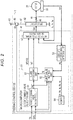
- the steering control device 1 includes a microcomputer 41 that outputs a motor control signal Sm and a drive circuit 42 that supplies drive power to the motor 21 based on the motor control signal Sm.
- a known PWM (Pulse Width Modulation) inverter including a plurality of switching elements such as FETs is employed as the drive circuit 42.
- the motor control signal Sm output from the microcomputer 41 defines ON and OFF states of the switching elements.
- the switching elements are turned on and off in response to the motor control signal Sm and a power supply pattern to motor coils is switched in phases, whereby a DC power of an onboard power supply 43 is converted into three-phase drive power and is output to the motor 21.
- Control blocks which will be described below are realized by a computer program which is executed by the microcomputer 41, state quantities are detected every predetermined sampling cycle, and calculation processes assigned to the following control blocks are performed every predetermined calculation cycle.
- the vehicle speed SPD, the steering torque Th, and the rotation angle ⁇ m of the motor 21 are input to the microcomputer 41.
- Phase current values Iu, Iv, and Iw of the motor 21 which are detected by a current sensor 44 and a source voltage Vb of an onboard power supply 43 which is detected by a voltage sensor 45 are also input to the microcomputer 41.
- the current sensor 44 is provided in a connection line 46 between the drive circuit 42 and a motor coil of each phase.
- the voltage sensor 45 is provided in a connection line 47 between the onboard power supply 43 and the drive circuit 42.
- FIG. 2 for the purpose of convenience of description, one of each of the current sensors 44 of the phases and the connection lines 46 of the phases is illustrated.
- the microcomputer 41 outputs the motor control signal Sm based on the input state quantities.
- the microcomputer 41 includes a current command value calculating unit 51 that calculates current command values Id* and Iq*, a motor control signal generating unit 52 that outputs the motor control signal Sm based on the current command values Id* and Iq*, and an absolute steering angle detecting unit 53 that detects an absolute steering angle ⁇ s.
- the vehicle speed SPD, the steering torque Th, and the absolute steering angle ⁇ s are input to the current command value calculating unit 51.
- the current command value calculating unit 51 calculates the current command values Id* and Iq* based on the input state quantities.
- the current command values Id* and Iq* are target values of currents to be supplied to the motor 21 and are a current command value on a d axis and a current command value on a q axis, respectively, in a d/q coordinate system.
- the q-axis current command value Iq* represents a target value of a motor torque which is output from the motor 21.
- the d-axis current command value Id* is basically fixed to zero.
- the current command values Id* and Iq* have positive values when steering to the right side is assisted with and have negative values when steering to the left side is assisted with.
- the current command values Id* and Iq*, the phase current values Iu, Iv, and Iw, and the rotation angle ⁇ m of the motor 21 are input to the motor control signal generating unit 52.
- the motor control signal generating unit 52 generates the motor control signal Sm by performing current feedback control in the d/q coordinate system based on the input state quantities.
- the motor control signal generating unit 52 calculates a d-axis current value Id and a q-axis current value Iq which are actual current values of the motor 21 in the d/q coordinate system by mapping the phase current values Iu, Iv, and Iw onto the d/q coordinate system based on the rotation angle ⁇ m.
- the motor control signal generating unit 52 generates the motor control signal Sm by performing current feedback control such that the d-axis current value Id follow the d-axis current command value Id* and the q-axis current value Iq follows the q-axis current command value Iq*.
- the motor control signal generating unit 52 outputs the generated motor control signal Sm to the drive circuit 42. Accordingly, by supplying drive power based on the motor control signal Sm to the motor 21 and outputting a motor torque based on the q-axis current command value Iq* from the motor 21, an assist force is applied to the steering mechanism 5.
- the rotation angle ⁇ m is input to the absolute steering angle detecting unit 53.
- the absolute steering angle detecting unit 53 detects an absolute motor angle which is expressed as an absolute angle including a range greater than 360° based on the rotation angle ⁇ m.
- the absolute steering angle detecting unit 53 in this embodiment integrates a rotation speed of the motor 21, for example, with an origin at the rotation angle ⁇ m when a start switch such as an ignition switch is turned on for the first time after the onboard power supply 43 has been replaced, and detects an absolute motor angle based on the integrated rotation speed and the rotation angle ⁇ m.
- the absolute steering angle detecting unit 53 detects an absolute steering angle ⁇ s indicating a steering angle of the steering shaft 11 by multiplying the absolute motor angle by a conversion factor based on a reduction gear ratio of the reduction gear mechanism 22.
- rotation of the motor 21 is monitored when the start switch is turned off, and the rotation speed of the motor 21 is normally integrated. Accordingly, even when the start switch is turned on a second time or later after the onboard power supply 43 has been replaced, the origin of the absolute steering angle ⁇ s is the same as the origin which was set when the start switch was turned on for the first time.
- the absolute steering angle ⁇ s indicates a rotation angle of a rotation shaft which can be converted to the turning angle of the turning wheels 4.
- the absolute motor angle and the absolute steering angle ⁇ s have positive values when they are angles turned to the right side from the origin and have negative values when they are angles turned to the left side from the origin.
- the configuration of the current command value calculating unit 51 includes an assist command value calculating unit 61 that calculates an assist command value Ias* which is a base component of the q-axis current command value Iq*.
- the current command value calculating unit 51 further includes a limit value setting unit 62 that sets a limit value Ig which is an upper limit of the absolute value of the q-axis current command value Iq* and a guard processing unit 63 that limits the absolute value of the assist command value Ias* to be equal to or less than the limit value Ig.
- the memory 64 is connected to the limit value setting unit 62.
- the steering torque Th and the vehicle speed SPD are input to the assist command value calculating unit 61.
- the assist command value calculating unit 61 calculates the assist command value Ias* based on the steering torque Th and the vehicle speed SPD. Specifically, the assist command value calculating unit 61 calculates the assist command value Ias* to have a larger absolute value as the absolute value of the steering torque Th becomes greater and as the vehicle speed SPD becomes lower.
- the absolute value of the assist command value Ias* is calculated to be equal to or less than a rated current Ir which is a maximum current corresponding to a torque which is set in advance as the motor torque which can be output from the motor 21.
- the calculated assist command value Ias* is output to the guard processing unit 63.
- the limit value Ig which is set by the limit value setting unit 62 in addition to the assist command value Ias* is input to the guard processing unit 63 as will be described later.
- the guard processing unit 63 outputs the value of the assist command value Ias* to the motor control signal generating unit 52 as the q-axis current command value Iq*.
- the guard processing unit 63 outputs a value obtained by limiting the absolute value of the assist command value Ias* to the limit value Ig to the motor control signal generating unit 52 as the q-axis current command value Iq*.
- the rated current Ir, end-position-corresponding angles ⁇ s_le and ⁇ s_re, and the like are stored in a memory 64.
- the left end-position-corresponding angle ⁇ s_le is the absolute steering angle ⁇ s corresponding to the left rack end position
- the right end-position-corresponding angle ⁇ s_re is the absolute steering angle ⁇ s corresponding to the right rack end position.
- the end-position-corresponding angles ⁇ s_le and ⁇ s_re are set, for example, by proper learning which is performed based on a driver's steering.
- the configuration of the limit value setting unit 62 will be described below.
- the absolute steering angle ⁇ s, the vehicle speed SPD, the source voltage Vb, the assist command value Ias*, the rated current Ir, and the end-position-corresponding angles ⁇ s_le and ⁇ s_re are input to the limit value setting unit 62.
- the limit value setting unit 62 sets the limit value Ig based on the input state quantities.
- the limit value setting unit 62 includes a steering angle limit value calculating unit 71 that calculates a steering angle limit value Ien based on the absolute steering angle ⁇ s, a voltage limit value calculating unit 72 that calculates a voltage limit value Ivb which is another limit value based on the source voltage Vb, and a minimum value selecting unit 73 that selects the smaller of the steering angle limit value Ien and the voltage limit value Ivb.
- the absolute steering angle ⁇ s, the vehicle speed SPD, the assist command value Ias*, the rated current Ir, and the end-position-corresponding angles ⁇ s_le and ⁇ s_re are input to the steering angle limit value calculating unit 71.
- the steering angle limit value calculating unit 71 calculates the steering angle limit value Ien which decreases with a decrease of an end separation angle ⁇ indicating a minimum distance of the absolute steering angle ⁇ s from the left and right end-position-corresponding angles ⁇ s_le and ⁇ s_re based on the input state quantities when the end separation angle ⁇ is equal to or less than a predetermined angle ⁇ 1 as will be described later.
- the calculated steering angle limit value Ien is output to the minimum value selecting unit 73.
- the source voltage Vb is input to the voltage limit value calculating unit 72.
- the voltage limit value calculating unit 72 calculates the voltage limit value Ivb less than a rated voltage for supplying the rated current Ir when the absolute value of the source voltage Vb is equal to or less than a preset voltage threshold value Vth. Specifically, when the absolute value of the source voltage Vb is equal to or less than the voltage threshold value Vth, the voltage limit value calculating unit 72 calculates the voltage limit value Ivb having a less absolute value with a decrease of the absolute value of the source voltage Vb. The calculated voltage limit value Ivb is output to the minimum value selecting unit 73.
- the minimum value selecting unit 73 selects the smaller of the steering angle limit value Ien and the voltage limit value Ivb as the limit value Ig and outputs the selected one to the guard processing unit 63.
- the absolute value of the q-axis current command value Iq* is limited to the steering angle limit value Ien. Accordingly, end contact relaxation control for relaxing an impact of an end contact is performed by decreasing the absolute value of the q-axis current command value Iq* based on the decrease of the end separation angle ⁇ when the end separation angle ⁇ is equal to or less than the predetermined angle ⁇ 1.
- the current command value calculating unit 51 in this embodiment corrects the q-axis current command value Iq* such that the absolute value of the q-axis current command value Iq* is limited to be equal to or less than the limit value Ig. Since the assist command value Ias* as a base component of the q-axis current command value Iq* is input to the guard processing unit 63 as described above, the assist command value Ias* corresponds to a current command value before being corrected.
- the absolute value of the q-axis current command value Iq* is limited to the voltage limit value Ivb. Accordingly, when the absolute value of the source voltage Vb is equal to or less than the voltage threshold value Vth, power supply protection control for decreasing the absolute value of the q-axis current command value Iq* with a decrease of the absolute value of the source voltage Vb is performed.
- the steering angle limit value calculating unit 71 includes an end separation angle calculating unit 81 that calculates the end separation angle ⁇ and an angle limiting component calculating unit 82 that calculates an angle limiting component Iga which is a current limit which is determined based on the end separation angle ⁇ , and calculates a pre-adjustment steering angle limit value Ienb by subtracting the angle limiting component Iga from the rated current Ir.
- the steering angle limit value calculating unit 71 further includes a steering angle limit value adjusting unit 83 that calculates a steering angle limit value Ien based on the pre-adjustment steering angle limit value Ienb.
- the absolute steering angle ⁇ s and the end-position-corresponding angles ⁇ s_le and ⁇ s_re are input to the end separation angle calculating unit 81.
- the end separation angle calculating unit 81 calculates a left end separation angle ⁇ l which is a difference between the absolute steering angle ⁇ s and the left end-position-corresponding angle ⁇ s_le in the newest calculation cycle and a right end separation angle ⁇ r which is a difference between the absolute steering angle ⁇ s and the right end-position-corresponding angle ⁇ s_re in the newest calculation cycle. Then, the end separation angle calculating unit 81 outputs one of the smaller absolute value of the right end separation angle ⁇ r and the left end separation angle ⁇ l as the end separation angle ⁇ to the angle limiting component calculating unit 82.
- the end separation angle calculating unit 81 sets a value of a steering angle position flag F indicating a position at which the steering wheel 3 is steered by comparing the absolute values of the right end separation angle ⁇ r and the left end separation angle ⁇ l with a preset end separation angle threshold value ⁇ th.
- the end separation angle threshold value ⁇ th indicates a threshold value for determining to which of the right and the left the steering wheel 3 is steered and is set to a large value of several hundreds.
- the end separation angle calculating unit 81 sets the value of the steering angle position flag F to "1" which indicates that the steering wheel 3 is steered in the positive direction, that is, that the turning wheels 4 are turned in the positive direction.
- the end separation angle calculating unit 81 sets the value of the steering angle position flag F to "2" which indicates that the steering wheel 3 is steered in the negative direction, that is, the turning wheels 4 are turned in the negative direction.
- the end separation angle calculating unit 81 sets the value of the steering angle position flag F to "0" which indicates that the steering wheel 3 is located in the vicinity of a neutral position.
- the end separation angle ⁇ and the vehicle speed SPD are input to the angle limiting component calculating unit 82.
- the angle limiting component calculating unit 82 includes a map in which a relationship between the end separation angle ⁇ and the vehicle speed SPD and the angle limiting component Iga is defined and calculates the angle limiting component Iga corresponding to the end separation angle ⁇ and the vehicle speed SPD with reference to the map.
- the angle limiting component Iga is set to decrease in proportion to an increase of the end separation angle ⁇ from a zero state, to reach zero when the end separation angle ⁇ is a predetermined angle ⁇ 1, and to be zero when the end separation angle ⁇ is greater than the predetermined angle ⁇ 1.
- an area in which the end separation angle ⁇ is negative is also set, and the angle limiting component Iga increases in proportion to a decrease of the end separation angle ⁇ when the end separation angle ⁇ becomes less than zero and is kept constant after angle limiting component Iga becomes the rated current Ir.
- the negative area in the map is assumed to be a degree by which the motor 21 rotates with elastic deformation of the EPS 2 by performing more turning steering in a state in which the rack end 18 comes into contact with the rack housing 13.
- the predetermined angle ⁇ 1 is set to a small angle indicating a range close to the end-position-corresponding angles ⁇ s_le and ⁇ s_re. That is, the angle limiting component Iga is set to decrease when the absolute steering angle ⁇ s transitions from the end-position-corresponding angles ⁇ s_le and ⁇ s_re to the neutral position of steering and to be zero when the absolute steering angle ⁇ s is located closer to the neutral position of steering than the vicinities of the end-position-corresponding angles ⁇ s_le and ⁇ s_re.
- the angle limiting component Iga is set to decrease with an increase of the vehicle speed SPD in an area in which the end separation angle ⁇ is equal to or less than the predetermined angle ⁇ 1. Specifically, the angle limiting component Iga is set to be greater than zero when the vehicle speed SPD is in a low-speed area, and the angle limiting component Iga is set to be zero when the vehicle speed SPD is in a middle-speed or high-speed area.
- the calculated angle limiting component Iga is output to a subtractor 84.
- the rated current Ir in addition to the angle limiting component Iga is input to the subtractor 84.
- the steering angle limit value calculating unit 71 outputs a value, which is obtained by subtracting the angle limiting component Iga from the rated current Ir in the subtractor 84, as a pre-adjustment steering angle limit value Ienb to the steering angle limit value adjusting unit 83.
- the steering angle limit value adjusting unit 83 calculates the steering angle limit value Ien by adjusting the pre-adjustment steering angle limit value Ienb and outputs the steering angle limit value Ien to the minimum value selecting unit 73.
- the configuration of the steering angle limit value adjusting unit 83 will be described below.
- the assist command value Ias* in addition to the pre-adjustment steering angle limit value Ienb is input to the steering angle limit value adjusting unit 83.
- the steering angle limit value adjusting unit 83 compares the assist command value Ias* with the pre-adjustment steering angle limit value Ienb with a positive sign (hereinafter referred to as a positive pre-adjustment steering angle limit value Ienb).
- the steering angle limit value adjusting unit 83 sets the absolute value of the steering angle limit value Ien to the rated current Ir.
- the steering angle limit value adjusting unit 83 sets the absolute value of the steering angle limit value Ien to the pre-adjustment steering angle limit value Ienb without any change.
- the steering angle limit value adjusting unit 83 compares the assist command value Ias* with the pre-adjustment steering angle limit value Ienb with a negative sign (hereinafter referred to as a negative pre-adjustment steering angle limit value Ienb).
- a negative pre-adjustment steering angle limit value Ienb a negative sign
- the steering angle limit value adjusting unit 83 sets the absolute value of the steering angle limit value Ien to the pre-adjustment steering angle limit value Ienb without any change.
- the steering angle limit value adjusting unit 83 sets the absolute value of the steering angle limit value Ien to the rated current Ir.
- the steering angle limit value adjusting unit 83 in this embodiment sets the absolute value of the steering angle limit value Ien to the rated current Ir at least when return steering is performed. Accordingly, when power supply protection control is not performed and the steering angle limit value Ien is the limit value Ig, the assist command value Ias* is output as the q-axis current command value Iq* without any change and correction of the q-axis current command value Iq* through end contact relaxation control is not performed even when the end separation angle ⁇ is equal to or less than the predetermined angle ⁇ 1.
- the q-axis current command value Iq* is limited even when the end separation angle ⁇ is equal to or less than the predetermined angle ⁇ 1 and return steering is performed.
- the steering angle limit value adjusting unit 83 determines whether the steering angle position flag F is set to "1," that is, whether steering is performed to the right side (Step 102).
- the steering angle position flag F is set to "1" (Step S102: YES)
- the assist command value Ias* is less than the positive pre-adjustment steering angle limit value Ienb (Step 103: YES)
- the absolute value of the steering angle limit value Ien is set to the rated current Ir (Step 104).
- Step 105 when the assist command value Ias* is equal to or greater than the positive pre-adjustment steering angle limit value Ienb (Step 103: NO), the absolute value of the steering angle limit value Ien is set to the pre-adjustment steering angle limit value Ienb (Step 105).
- the steering angle limit value adjusting unit 83 determines whether the steering angle position flag F is set to "2," that is, whether steering is performed to the left side (Step 106).
- the steering angle position flag F is set to "2" (Step 106: YES)
- Step 107 When the assist command value Ias* is equal to or less than the negative pre-adjustment steering angle limit value Ienb (Step 107: YES), the absolute value of the steering angle limit value Ien is set to the pre-adjustment steering angle limit value Ienb in Step 105. On the other hand, when the assist command value Ias* is greater than the negative pre-adjustment steering angle limit value Ienb (Step 107: NO), the absolute value of the steering angle limit value Ien is set to the rated current Ir in Step 104.
- Step 106 When it is determined in Step 106 that the steering angle position flag F is not set to "2," that is, when the steering angle position flag F is set to "0" and the steering wheel 3 is located in the vicinity of the neutral position (Step 106: NO), the steering angle limit value adjusting unit 83 does not perform the processes subsequent thereto.
- the steering angle limit value Ien is set in consideration of the steering direction in the absolute steering angle ⁇ s.
- the pre-adjustment steering angle limit value Ienb is indicated by a dotted line.
- an area in which the absolute value of the steering angle limit value Ien is the rated current Ir is illustrated to be hatched.
- the end separation angle ⁇ becomes equal to or less than the predetermined angle ⁇ 1 by steering to the right side and the absolute value of the assist command value Ias* becomes a predetermined value Ias1 greater than the pre-adjustment steering angle limit value Ienb by further performing turning steering.
- the absolute value of the steering angle limit value Ien becomes the pre-adjustment steering angle limit value Ienb less than the predetermined value Ias1 and the absolute value of the q-axis current command value Iq* is limited to the steering angle limit value Ien. Accordingly, an impact of an end contact is relaxed.
- the sign of the assist command value Ias* is negative and the absolute value thereof becomes a predetermined value "Ias1" greater than the pre-adjustment steering angle limit value Ienb by performing return steering after the end separation angle ⁇ becomes equal to or less than the predetermined angle ⁇ 1 by steering to the right side.
- the absolute value of the steering angle limit value Ien is the pre-adjustment steering angle limit value Ienb, the absolute value of the q-axis current command value Iq* is limited to the steering angle limit value Ien which is less than the predetermined value Ias1. Accordingly, an assist force may be insufficient and a hooked feeling may be caused.
- the absolute value of the steering angle limit value Ien is the rated current Ir and thus the absolute value of the q-axis current command value Iq* is not limited to the predetermined value Ias1. Accordingly, since a sufficient assist force is applied to the steering mechanism 5, a hooked feeling is not easily caused.
- the current command value calculating unit 51 calculates the q-axis current command value Iq* such that an increase of the end separation angle ⁇ is not regulated through end contact relaxation control when the end separation angle ⁇ is equal to or less than the predetermined angle ⁇ 1. Accordingly, for example, since an assist force which is applied to the steering mechanism 5 is not easily insufficient when return steering is performed from the vicinity of the rack end position, a hooked feeling is not likely to be caused and it is possible to curb degradation in a steering feeling.
- the current command value calculating unit 51 performs end contact relaxation control by limiting the absolute value of the q-axis current command value Iq* to the steering angle limit value Ien.
- the steering angle limit value calculating unit 71 sets the absolute value of the steering angle limit value Ien to the rated current Ir when the end separation angle ⁇ is equal to or less than the predetermined angle ⁇ 1 and return steering in which the end separation angle ⁇ increases is performed. Accordingly, when power supply protection control is not performed, the absolute value of the q-axis current command value Iq* is not limited and the increase of the end separation angle ⁇ is not regulated suitably.
- the steering angle limit value calculating unit 71 sets the absolute value of the steering angle limit value Ien to the rated current Ir when the assist command value Ias* is less than the positive pre-adjustment steering angle limit value Ienb, and sets the absolute value of the steering angle limit value Ien to the pre-adjustment steering angle limit value Ienb when the assist command value Ias* is equal to or greater than the positive pre-adjustment steering angle limit value Ienb.
- the steering angle limit value adjusting unit 83 sets the absolute value of the steering angle limit value Ien to the rated current Ir when the assist command value Ias* is equal to or greater than the negative pre-adjustment steering angle limit value Ienb and sets the absolute value of the steering angle limit value Ien to the pre-adjustment steering angle limit value Ienb when the assist command value Ias* is less than the negative pre-adjustment steering angle limit value Ienb.
- the steering angle limit value calculating unit 71 can easily set the absolute value of the steering angle limit value Ien to an appropriate value corresponding to steering by comparing the assist command value Ias* with the pre-adjustment steering angle limit value Ienb in consideration of the sign, for example, even when it is not directly determined whether return steering or turning steering is performed based on the state quantities such as the steering torque Th.
- the steering angle limit value calculating unit 71 compares the absolute values of the right end separation angle ⁇ r and the left end separation angle ⁇ l with the end separation angle threshold value ⁇ th, determines that the turning wheels 4 are turned to the right side when the absolute value of the right end separation angle ⁇ r is less than the end separation angle threshold value ⁇ th, and determines that the turning wheels 4 are turned to the left side when the absolute value of the left end separation angle ⁇ l is less than the end separation angle threshold value ⁇ th. Accordingly, it is possible to easily determine the direction in which the turning wheels 4 are turned based on the absolute values of the right end separation angle ⁇ r and the left end separation angle ⁇ l.
- the direction in which the turning wheels 4 are turned is determined based on the absolute values of the right end separation angle ⁇ r and the left end separation angle ⁇ l, but the invention is not limited thereto and the direction in which the turning wheels 4 are turned may be determined, for example, based on the absolute steering angle ⁇ s.
- the absolute value of the steering angle limit value Ien is set to the rated current Ir even in a state in which turning steering to the right side is performed and return steering is not yet performed.
- the invention is not limited thereto and it may be determined whether the sign of the assist command value Ias* is negative in addition to whether the assist command value Ias* is less than the positive pre-adjustment steering angle limit value Ienb and the absolute value of the steering angle limit value Ien may be set to the rated current Ir only when the sign of the assist command value Ias* is negative.
- the absolute value of the q-axis current command value Iq* when the steering angle limit value Ien is used as the limit value Ig has the same magnitude as in the above embodiment.
- the absolute value of the steering angle limit value Ien may be set to the rated current Ir only when the sign of the assist command value Ias* is positive.
- the absolute value of the steering angle limit value Ien when steering is performed to the right side, the absolute value of the steering angle limit value Ien is set to the rated current Ir when the assist command value Ias* is less than the positive pre-adjustment steering angle limit value Ienb, but the invention is not limited thereto and the absolute value of the steering angle limit value Ien may be set to a value less than the rated current Ir when the increase of the end separation angle ⁇ is not regulated.
- the absolute value of the steering angle limit value Ien when steering is performed to the left side, the absolute value of the steering angle limit value Ien may be set to a value less than the rated current Ir when the assist command value Ias* is equal to or greater than the negative pre-adjustment steering angle limit value Ienb.
- the rotation speed of the motor 21 from the origin is normally integrated and the absolute motor angle and the absolute steering angle ⁇ s are detected.
- the invention is not limited thereto and, for example, a steering sensor that detects a steering angle as an absolute angle may be provided, the rotation speed of the motor 21 from the origin may be integrated based on the steering angle detected by the steering sensor and the reduction gear ratio of the reduction gear mechanism 22, and the absolute motor angle and the absolute steering angle ⁇ s may be detected.
- end contact relaxation control is performed by limiting the assist command value Ias* to the steering angle limit value Ien, but the invention is not limited thereto and end contact relaxation control may be performed, for example, by adding a steering reaction component increasing as it approaches the rack end position, that is, a component with a sign opposite to the sign of the assist command value Ias*, to the assist command value Ias*.
- end contact relaxation control may be performed, for example, by adding a steering reaction component increasing as it approaches the rack end position, that is, a component with a sign opposite to the sign of the assist command value Ias*.
- a guard process is performed on the assist command value Ias*, but the invention is not limited thereto and, for example, a guard process may be performed on a value obtained by correcting the assist command value Ias* using a compensation value based on a torque differential value obtained by differentiating the steering torque Th.
- the value obtained by correcting the assist command value Ias* corresponds to a current command value before being corrected.
- the limit value setting unit 62 includes the voltage limit value calculating unit 72 that calculates the voltage limit value Ivb based on the source voltage Vb, but the invention is not limited thereto and another calculation unit that calculates another limit value based on another state quantity may be provided in addition to or instead of the voltage limit value calculating unit 72.
- a configuration in which the limit value setting unit 62 does not include the voltage limit value calculating unit 72 and sets the steering angle limit value Ien as the limit value Ig without any change may be employed.
- a value obtained by subtracting the angle limiting component Iga from the rated current Ir is used as the pre-adjustment steering angle limit value Ienb, but the invention is not limited thereto and a value obtained by subtracting the angle limiting component Iga and a current limit value which is determined depending on a motor angular velocity from the rated current Ir may be used as the pre-adjustment steering angle limit value Ienb.
- the steering control device 1 controls the EPS 2 of a type in which the EPS actuator 6 applies a motor torque to the column shaft 15, but the invention is not limited thereto and, for example, the steering control device 1 may control a steering system of a type in which a motor torque is applied to the rack shaft 12 via a ball screw nut.
- the steering control device 1 may control a steer-by-wire type steering device in which transmission of power between a steering unit which is operated by a driver and a turning unit that turns the turning wheels is cut off and end contact relaxation control may be performed on a torque command value or a q-axis current command value of a motor of a turning actuator which is provided in the turning unit as in this embodiment.
Landscapes
- Engineering & Computer Science (AREA)
- Chemical & Material Sciences (AREA)
- Combustion & Propulsion (AREA)
- Transportation (AREA)
- Mechanical Engineering (AREA)
- Steering Control In Accordance With Driving Conditions (AREA)
- Power Steering Mechanism (AREA)
Applications Claiming Priority (1)
| Application Number | Priority Date | Filing Date | Title |
|---|---|---|---|
| JP2019166943A JP7306928B2 (ja) | 2019-09-13 | 2019-09-13 | 操舵制御装置 |
Publications (2)
| Publication Number | Publication Date |
|---|---|
| EP3795454A1 true EP3795454A1 (fr) | 2021-03-24 |
| EP3795454B1 EP3795454B1 (fr) | 2023-11-15 |
Family
ID=72474100
Family Applications (1)
| Application Number | Title | Priority Date | Filing Date |
|---|---|---|---|
| EP20195731.3A Active EP3795454B1 (fr) | 2019-09-13 | 2020-09-11 | Dispositif de commande de direction |
Country Status (4)
| Country | Link |
|---|---|
| US (1) | US11897555B2 (fr) |
| EP (1) | EP3795454B1 (fr) |
| JP (1) | JP7306928B2 (fr) |
| CN (1) | CN112498468A (fr) |
Families Citing this family (1)
| Publication number | Priority date | Publication date | Assignee | Title |
|---|---|---|---|---|
| CN112550439A (zh) * | 2019-09-26 | 2021-03-26 | 株式会社捷太格特 | 转向控制装置 |
Citations (14)
| Publication number | Priority date | Publication date | Assignee | Title |
|---|---|---|---|---|
| EP1167158A1 (fr) * | 2000-06-23 | 2002-01-02 | Société de Mécanique d'Irigny | Direction assistée électrique pour véhicule automobile |
| US6408235B1 (en) * | 1999-09-17 | 2002-06-18 | Delphi Technologies, Inc. | End-of-travel impact management system |
| US6694237B2 (en) * | 2001-08-30 | 2004-02-17 | Mitsubishi Denki Kabushiki Kaisha | Steering control device |
| WO2004022411A1 (fr) * | 2002-09-06 | 2004-03-18 | Volkswagen | Dispositif et procede relatifs a une direction assistee pour vehicules a moteur a direction electromecanique |
| US20040098180A1 (en) * | 2001-04-09 | 2004-05-20 | Klaus Von Hammel | Motor-driven power steering unit |
| EP1602993A2 (fr) * | 2004-06-01 | 2005-12-07 | Renault S.A.S. | Procédé de commande d'un organe au moyen d'une consigne de position |
| JP2008284889A (ja) * | 2007-05-15 | 2008-11-27 | Nsk Ltd | 電動パワーステアリング装置の制御装置 |
| EP2361820A2 (fr) * | 2010-02-19 | 2011-08-31 | Bayerische Motoren Werke Aktiengesellschaft | Système de guidage de véhicule doté d'un soutien du moment de couple électro-motorisé |
| DE102011085382A1 (de) * | 2011-10-28 | 2013-05-02 | Bayerische Motoren Werke Aktiengesellschaft | Betriebsverfahren eines Fahrzeug-Lenksystems mit Servoantrieb und einem Lenkwinkel-Überlagerungsmittel |
| US20140188337A1 (en) * | 2012-02-07 | 2014-07-03 | Mando Corporation | Electric power steering apparatus and method of controlling the same |
| JP5962881B1 (ja) | 2014-10-01 | 2016-08-03 | 日本精工株式会社 | 電動パワーステアリング装置 |
| JP2016155519A (ja) * | 2015-02-26 | 2016-09-01 | 日立オートモティブシステムズ株式会社 | パワーステアリング装置の制御装置 |
| DE102015211711A1 (de) * | 2015-06-24 | 2016-12-29 | Volkswagen Aktiengesellschaft | Verfahren und Vorrichtung zum Betreiben eines Lenksystems |
| US20190233000A1 (en) * | 2018-01-26 | 2019-08-01 | Jtekt Corporation | Steering control device |
Family Cites Families (7)
| Publication number | Priority date | Publication date | Assignee | Title |
|---|---|---|---|---|
| JP2004175196A (ja) | 2002-11-26 | 2004-06-24 | Koyo Seiko Co Ltd | 電動パワーステアリング装置 |
| JP2008049914A (ja) | 2006-08-25 | 2008-03-06 | Nsk Ltd | 電動パワーステアリング装置の制御装置 |
| JP5267031B2 (ja) | 2008-10-09 | 2013-08-21 | 株式会社ジェイテクト | 電動パワーステアリング装置 |
| JP2011126477A (ja) | 2009-12-21 | 2011-06-30 | Hitachi Automotive Systems Ltd | パワーステアリング装置 |
| JP2014189115A (ja) | 2013-03-27 | 2014-10-06 | Hitachi Automotive Systems Steering Ltd | 舵角検出装置 |
| JP5971426B2 (ja) | 2013-10-01 | 2016-08-17 | 日本精工株式会社 | 電動パワーステアリング装置 |
| JP7067169B2 (ja) | 2017-05-30 | 2022-05-16 | 株式会社ジェイテクト | 操舵制御装置 |
-
2019
- 2019-09-13 JP JP2019166943A patent/JP7306928B2/ja active Active
-
2020
- 2020-09-10 CN CN202010948060.1A patent/CN112498468A/zh active Pending
- 2020-09-11 EP EP20195731.3A patent/EP3795454B1/fr active Active
- 2020-09-11 US US17/017,828 patent/US11897555B2/en active Active
Patent Citations (14)
| Publication number | Priority date | Publication date | Assignee | Title |
|---|---|---|---|---|
| US6408235B1 (en) * | 1999-09-17 | 2002-06-18 | Delphi Technologies, Inc. | End-of-travel impact management system |
| EP1167158A1 (fr) * | 2000-06-23 | 2002-01-02 | Société de Mécanique d'Irigny | Direction assistée électrique pour véhicule automobile |
| US20040098180A1 (en) * | 2001-04-09 | 2004-05-20 | Klaus Von Hammel | Motor-driven power steering unit |
| US6694237B2 (en) * | 2001-08-30 | 2004-02-17 | Mitsubishi Denki Kabushiki Kaisha | Steering control device |
| WO2004022411A1 (fr) * | 2002-09-06 | 2004-03-18 | Volkswagen | Dispositif et procede relatifs a une direction assistee pour vehicules a moteur a direction electromecanique |
| EP1602993A2 (fr) * | 2004-06-01 | 2005-12-07 | Renault S.A.S. | Procédé de commande d'un organe au moyen d'une consigne de position |
| JP2008284889A (ja) * | 2007-05-15 | 2008-11-27 | Nsk Ltd | 電動パワーステアリング装置の制御装置 |
| EP2361820A2 (fr) * | 2010-02-19 | 2011-08-31 | Bayerische Motoren Werke Aktiengesellschaft | Système de guidage de véhicule doté d'un soutien du moment de couple électro-motorisé |
| DE102011085382A1 (de) * | 2011-10-28 | 2013-05-02 | Bayerische Motoren Werke Aktiengesellschaft | Betriebsverfahren eines Fahrzeug-Lenksystems mit Servoantrieb und einem Lenkwinkel-Überlagerungsmittel |
| US20140188337A1 (en) * | 2012-02-07 | 2014-07-03 | Mando Corporation | Electric power steering apparatus and method of controlling the same |
| JP5962881B1 (ja) | 2014-10-01 | 2016-08-03 | 日本精工株式会社 | 電動パワーステアリング装置 |
| JP2016155519A (ja) * | 2015-02-26 | 2016-09-01 | 日立オートモティブシステムズ株式会社 | パワーステアリング装置の制御装置 |
| DE102015211711A1 (de) * | 2015-06-24 | 2016-12-29 | Volkswagen Aktiengesellschaft | Verfahren und Vorrichtung zum Betreiben eines Lenksystems |
| US20190233000A1 (en) * | 2018-01-26 | 2019-08-01 | Jtekt Corporation | Steering control device |
Also Published As
| Publication number | Publication date |
|---|---|
| EP3795454B1 (fr) | 2023-11-15 |
| US20210078628A1 (en) | 2021-03-18 |
| JP7306928B2 (ja) | 2023-07-11 |
| CN112498468A (zh) | 2021-03-16 |
| JP2021041877A (ja) | 2021-03-18 |
| US11897555B2 (en) | 2024-02-13 |
Similar Documents
| Publication | Publication Date | Title |
|---|---|---|
| CN110696909B (zh) | 转向控制装置和转向控制方法 | |
| CN110539791B (zh) | 转向控制装置 | |
| EP3854663B1 (fr) | Dispositif de commande de direction | |
| EP3798096B1 (fr) | Dispositif de commande de direction | |
| EP3812243A1 (fr) | Dispositif de commande de direction | |
| EP3795454A1 (fr) | Dispositif de commande de direction | |
| EP3792151B1 (fr) | Dispositif de commande de direction | |
| CN111114625A (zh) | 转向操纵控制装置 | |
| EP3792152A1 (fr) | Dispositif de commande de direction |
Legal Events
| Date | Code | Title | Description |
|---|---|---|---|
| PUAI | Public reference made under article 153(3) epc to a published international application that has entered the european phase |
Free format text: ORIGINAL CODE: 0009012 |
|
| STAA | Information on the status of an ep patent application or granted ep patent |
Free format text: STATUS: THE APPLICATION HAS BEEN PUBLISHED |
|
| AK | Designated contracting states |
Kind code of ref document: A1 Designated state(s): AL AT BE BG CH CY CZ DE DK EE ES FI FR GB GR HR HU IE IS IT LI LT LU LV MC MK MT NL NO PL PT RO RS SE SI SK SM TR |
|
| AX | Request for extension of the european patent |
Extension state: BA ME |
|
| STAA | Information on the status of an ep patent application or granted ep patent |
Free format text: STATUS: REQUEST FOR EXAMINATION WAS MADE |
|
| 17P | Request for examination filed |
Effective date: 20210803 |
|
| RBV | Designated contracting states (corrected) |
Designated state(s): AL AT BE BG CH CY CZ DE DK EE ES FI FR GB GR HR HU IE IS IT LI LT LU LV MC MK MT NL NO PL PT RO RS SE SI SK SM TR |
|
| RAP3 | Party data changed (applicant data changed or rights of an application transferred) |
Owner name: JTEKT CORPORATION |
|
| GRAP | Despatch of communication of intention to grant a patent |
Free format text: ORIGINAL CODE: EPIDOSNIGR1 |
|
| STAA | Information on the status of an ep patent application or granted ep patent |
Free format text: STATUS: GRANT OF PATENT IS INTENDED |
|
| INTG | Intention to grant announced |
Effective date: 20230509 |
|
| GRAS | Grant fee paid |
Free format text: ORIGINAL CODE: EPIDOSNIGR3 |
|
| GRAA | (expected) grant |
Free format text: ORIGINAL CODE: 0009210 |
|
| STAA | Information on the status of an ep patent application or granted ep patent |
Free format text: STATUS: THE PATENT HAS BEEN GRANTED |
|
| RIN1 | Information on inventor provided before grant (corrected) |
Inventor name: EZAKI, YUKINOBU Inventor name: YAMAGUCHI, TAKAFUMI Inventor name: KATAOKA, NOBUAKI Inventor name: TOKO, TAKAHIRO |
|
| AK | Designated contracting states |
Kind code of ref document: B1 Designated state(s): AL AT BE BG CH CY CZ DE DK EE ES FI FR GB GR HR HU IE IS IT LI LT LU LV MC MK MT NL NO PL PT RO RS SE SI SK SM TR |
|
| REG | Reference to a national code |
Ref country code: CH Ref legal event code: EP Ref country code: GB Ref legal event code: FG4D |
|
| REG | Reference to a national code |
Ref country code: DE Ref legal event code: R096 Ref document number: 602020020997 Country of ref document: DE |
|
| REG | Reference to a national code |
Ref country code: IE Ref legal event code: FG4D |
|
| REG | Reference to a national code |
Ref country code: LT Ref legal event code: MG9D |
|
| REG | Reference to a national code |
Ref country code: NL Ref legal event code: MP Effective date: 20231115 |
|
| PG25 | Lapsed in a contracting state [announced via postgrant information from national office to epo] |
Ref country code: GR Free format text: LAPSE BECAUSE OF FAILURE TO SUBMIT A TRANSLATION OF THE DESCRIPTION OR TO PAY THE FEE WITHIN THE PRESCRIBED TIME-LIMIT Effective date: 20240216 |
|
| PG25 | Lapsed in a contracting state [announced via postgrant information from national office to epo] |
Ref country code: IS Free format text: LAPSE BECAUSE OF FAILURE TO SUBMIT A TRANSLATION OF THE DESCRIPTION OR TO PAY THE FEE WITHIN THE PRESCRIBED TIME-LIMIT Effective date: 20240315 |
|
| PG25 | Lapsed in a contracting state [announced via postgrant information from national office to epo] |
Ref country code: LT Free format text: LAPSE BECAUSE OF FAILURE TO SUBMIT A TRANSLATION OF THE DESCRIPTION OR TO PAY THE FEE WITHIN THE PRESCRIBED TIME-LIMIT Effective date: 20231115 |
|
| REG | Reference to a national code |
Ref country code: AT Ref legal event code: MK05 Ref document number: 1631519 Country of ref document: AT Kind code of ref document: T Effective date: 20231115 |
|
| PG25 | Lapsed in a contracting state [announced via postgrant information from national office to epo] |
Ref country code: NL Free format text: LAPSE BECAUSE OF FAILURE TO SUBMIT A TRANSLATION OF THE DESCRIPTION OR TO PAY THE FEE WITHIN THE PRESCRIBED TIME-LIMIT Effective date: 20231115 |
|
| PG25 | Lapsed in a contracting state [announced via postgrant information from national office to epo] |
Ref country code: AT Free format text: LAPSE BECAUSE OF FAILURE TO SUBMIT A TRANSLATION OF THE DESCRIPTION OR TO PAY THE FEE WITHIN THE PRESCRIBED TIME-LIMIT Effective date: 20231115 |
|
| PG25 | Lapsed in a contracting state [announced via postgrant information from national office to epo] |
Ref country code: ES Free format text: LAPSE BECAUSE OF FAILURE TO SUBMIT A TRANSLATION OF THE DESCRIPTION OR TO PAY THE FEE WITHIN THE PRESCRIBED TIME-LIMIT Effective date: 20231115 |
|
| PG25 | Lapsed in a contracting state [announced via postgrant information from national office to epo] |
Ref country code: NL Free format text: LAPSE BECAUSE OF FAILURE TO SUBMIT A TRANSLATION OF THE DESCRIPTION OR TO PAY THE FEE WITHIN THE PRESCRIBED TIME-LIMIT Effective date: 20231115 Ref country code: LT Free format text: LAPSE BECAUSE OF FAILURE TO SUBMIT A TRANSLATION OF THE DESCRIPTION OR TO PAY THE FEE WITHIN THE PRESCRIBED TIME-LIMIT Effective date: 20231115 Ref country code: IS Free format text: LAPSE BECAUSE OF FAILURE TO SUBMIT A TRANSLATION OF THE DESCRIPTION OR TO PAY THE FEE WITHIN THE PRESCRIBED TIME-LIMIT Effective date: 20240315 Ref country code: GR Free format text: LAPSE BECAUSE OF FAILURE TO SUBMIT A TRANSLATION OF THE DESCRIPTION OR TO PAY THE FEE WITHIN THE PRESCRIBED TIME-LIMIT Effective date: 20240216 Ref country code: ES Free format text: LAPSE BECAUSE OF FAILURE TO SUBMIT A TRANSLATION OF THE DESCRIPTION OR TO PAY THE FEE WITHIN THE PRESCRIBED TIME-LIMIT Effective date: 20231115 Ref country code: BG Free format text: LAPSE BECAUSE OF FAILURE TO SUBMIT A TRANSLATION OF THE DESCRIPTION OR TO PAY THE FEE WITHIN THE PRESCRIBED TIME-LIMIT Effective date: 20240215 Ref country code: AT Free format text: LAPSE BECAUSE OF FAILURE TO SUBMIT A TRANSLATION OF THE DESCRIPTION OR TO PAY THE FEE WITHIN THE PRESCRIBED TIME-LIMIT Effective date: 20231115 Ref country code: PT Free format text: LAPSE BECAUSE OF FAILURE TO SUBMIT A TRANSLATION OF THE DESCRIPTION OR TO PAY THE FEE WITHIN THE PRESCRIBED TIME-LIMIT Effective date: 20240315 |