EP3795430B1 - Vehicle with seat belt fastening indicator - Google Patents
Vehicle with seat belt fastening indicator Download PDFInfo
- Publication number
- EP3795430B1 EP3795430B1 EP20151686.1A EP20151686A EP3795430B1 EP 3795430 B1 EP3795430 B1 EP 3795430B1 EP 20151686 A EP20151686 A EP 20151686A EP 3795430 B1 EP3795430 B1 EP 3795430B1
- Authority
- EP
- European Patent Office
- Prior art keywords
- state
- seat belt
- check
- vehicle
- seatbelt
- Prior art date
- Legal status (The legal status is an assumption and is not a legal conclusion. Google has not performed a legal analysis and makes no representation as to the accuracy of the status listed.)
- Active
Links
Images


Classifications
-
- B—PERFORMING OPERATIONS; TRANSPORTING
- B60—VEHICLES IN GENERAL
- B60R—VEHICLES, VEHICLE FITTINGS, OR VEHICLE PARTS, NOT OTHERWISE PROVIDED FOR
- B60R22/00—Safety belts or body harnesses in vehicles
- B60R22/48—Control systems, alarms, or interlock systems, for the correct application of the belt or harness
-
- B—PERFORMING OPERATIONS; TRANSPORTING
- B60—VEHICLES IN GENERAL
- B60K—ARRANGEMENT OR MOUNTING OF PROPULSION UNITS OR OF TRANSMISSIONS IN VEHICLES; ARRANGEMENT OR MOUNTING OF PLURAL DIVERSE PRIME-MOVERS IN VEHICLES; AUXILIARY DRIVES FOR VEHICLES; INSTRUMENTATION OR DASHBOARDS FOR VEHICLES; ARRANGEMENTS IN CONNECTION WITH COOLING, AIR INTAKE, GAS EXHAUST OR FUEL SUPPLY OF PROPULSION UNITS IN VEHICLES
- B60K35/00—Instruments specially adapted for vehicles; Arrangement of instruments in or on vehicles
- B60K35/10—Input arrangements, i.e. from user to vehicle, associated with vehicle functions or specially adapted therefor
-
- B—PERFORMING OPERATIONS; TRANSPORTING
- B60—VEHICLES IN GENERAL
- B60K—ARRANGEMENT OR MOUNTING OF PROPULSION UNITS OR OF TRANSMISSIONS IN VEHICLES; ARRANGEMENT OR MOUNTING OF PLURAL DIVERSE PRIME-MOVERS IN VEHICLES; AUXILIARY DRIVES FOR VEHICLES; INSTRUMENTATION OR DASHBOARDS FOR VEHICLES; ARRANGEMENTS IN CONNECTION WITH COOLING, AIR INTAKE, GAS EXHAUST OR FUEL SUPPLY OF PROPULSION UNITS IN VEHICLES
- B60K35/00—Instruments specially adapted for vehicles; Arrangement of instruments in or on vehicles
- B60K35/20—Output arrangements, i.e. from vehicle to user, associated with vehicle functions or specially adapted therefor
- B60K35/26—Output arrangements, i.e. from vehicle to user, associated with vehicle functions or specially adapted therefor using acoustic output
-
- B—PERFORMING OPERATIONS; TRANSPORTING
- B60—VEHICLES IN GENERAL
- B60N—SEATS SPECIALLY ADAPTED FOR VEHICLES; VEHICLE PASSENGER ACCOMMODATION NOT OTHERWISE PROVIDED FOR
- B60N2/00—Seats specially adapted for vehicles; Arrangement or mounting of seats in vehicles
- B60N2/002—Seats provided with an occupancy detection means mounted therein or thereon
- B60N2/0021—Seats provided with an occupancy detection means mounted therein or thereon characterised by the type of sensor or measurement
- B60N2/0024—Seats provided with an occupancy detection means mounted therein or thereon characterised by the type of sensor or measurement for identifying, categorising or investigation of the occupant or object on the seat
-
- B—PERFORMING OPERATIONS; TRANSPORTING
- B60—VEHICLES IN GENERAL
- B60R—VEHICLES, VEHICLE FITTINGS, OR VEHICLE PARTS, NOT OTHERWISE PROVIDED FOR
- B60R21/00—Arrangements or fittings on vehicles for protecting or preventing injuries to occupants or pedestrians in case of accidents or other traffic risks
- B60R21/01—Electrical circuits for triggering passive safety arrangements, e.g. airbags, safety belt tighteners, in case of vehicle accidents or impending vehicle accidents
- B60R21/015—Electrical circuits for triggering passive safety arrangements, e.g. airbags, safety belt tighteners, in case of vehicle accidents or impending vehicle accidents including means for detecting the presence or position of passengers, passenger seats or child seats, and the related safety parameters therefor, e.g. speed or timing of airbag inflation in relation to occupant position or seat belt use
- B60R21/01512—Passenger detection systems
- B60R21/0153—Passenger detection systems using field detection presence sensors
- B60R21/01534—Passenger detection systems using field detection presence sensors using electromagneticwaves, e.g. infrared
-
- B—PERFORMING OPERATIONS; TRANSPORTING
- B60—VEHICLES IN GENERAL
- B60R—VEHICLES, VEHICLE FITTINGS, OR VEHICLE PARTS, NOT OTHERWISE PROVIDED FOR
- B60R21/00—Arrangements or fittings on vehicles for protecting or preventing injuries to occupants or pedestrians in case of accidents or other traffic risks
- B60R21/01—Electrical circuits for triggering passive safety arrangements, e.g. airbags, safety belt tighteners, in case of vehicle accidents or impending vehicle accidents
- B60R21/015—Electrical circuits for triggering passive safety arrangements, e.g. airbags, safety belt tighteners, in case of vehicle accidents or impending vehicle accidents including means for detecting the presence or position of passengers, passenger seats or child seats, and the related safety parameters therefor, e.g. speed or timing of airbag inflation in relation to occupant position or seat belt use
- B60R21/01512—Passenger detection systems
- B60R21/01544—Passenger detection systems detecting seat belt parameters, e.g. length, tension or height-adjustment
-
- B—PERFORMING OPERATIONS; TRANSPORTING
- B60—VEHICLES IN GENERAL
- B60N—SEATS SPECIALLY ADAPTED FOR VEHICLES; VEHICLE PASSENGER ACCOMMODATION NOT OTHERWISE PROVIDED FOR
- B60N2210/00—Sensor types, e.g. for passenger detection systems or for controlling seats
- B60N2210/10—Field detection presence sensors
- B60N2210/16—Electromagnetic waves
- B60N2210/20—Radar
-
- B—PERFORMING OPERATIONS; TRANSPORTING
- B60—VEHICLES IN GENERAL
- B60N—SEATS SPECIALLY ADAPTED FOR VEHICLES; VEHICLE PASSENGER ACCOMMODATION NOT OTHERWISE PROVIDED FOR
- B60N2230/00—Communication or electronic aspects
- B60N2230/30—Signal processing of sensor data
-
- B—PERFORMING OPERATIONS; TRANSPORTING
- B60—VEHICLES IN GENERAL
- B60R—VEHICLES, VEHICLE FITTINGS, OR VEHICLE PARTS, NOT OTHERWISE PROVIDED FOR
- B60R21/00—Arrangements or fittings on vehicles for protecting or preventing injuries to occupants or pedestrians in case of accidents or other traffic risks
- B60R21/01—Electrical circuits for triggering passive safety arrangements, e.g. airbags, safety belt tighteners, in case of vehicle accidents or impending vehicle accidents
- B60R2021/01204—Actuation parameters of safety arrangents
- B60R2021/01252—Devices other than bags
- B60R2021/01265—Seat belts
-
- B—PERFORMING OPERATIONS; TRANSPORTING
- B60—VEHICLES IN GENERAL
- B60R—VEHICLES, VEHICLE FITTINGS, OR VEHICLE PARTS, NOT OTHERWISE PROVIDED FOR
- B60R22/00—Safety belts or body harnesses in vehicles
- B60R22/48—Control systems, alarms, or interlock systems, for the correct application of the belt or harness
- B60R2022/4808—Sensing means arrangements therefor
-
- B—PERFORMING OPERATIONS; TRANSPORTING
- B60—VEHICLES IN GENERAL
- B60R—VEHICLES, VEHICLE FITTINGS, OR VEHICLE PARTS, NOT OTHERWISE PROVIDED FOR
- B60R22/00—Safety belts or body harnesses in vehicles
- B60R22/48—Control systems, alarms, or interlock systems, for the correct application of the belt or harness
- B60R2022/4866—Displaying or indicating arrangements thereof
Definitions
- the present disclosure relates to a vehicle capable of appropriately providing a notification regarding seat belt wearing and a method of controlling the same.
- a method for recognizing a seat occupancy of seats in a motor vehicle is known, for example, from US 2018/0222346 A1 .
- the conventional technology provides a notification regarding a seat belt for more than 60 seconds unconditionally when the vehicle is turned on.
- Such a conventional technology which provide the notification regarding the seat belt regardless of whether the passenger rides the vehicle, may bother the driver.
- a vehicle provided with a seating sensor may determine that a person has boarded the vehicle when a heavy load is placed on the seat, and provides an undesired inappropriate seat belt notification.
- the present disclosure provides a vehicle capable of identifying the type of an object occupying the vehicle by using a radar provided in the vehicle and determining an operating state of a seat belt indicator according to the type of the object, and a method of controlling the same.
- the present disclosure also provides a vehicle capable of preventing an undesired inappropriate notification by turning on/off the operation of the seatbelt indicator according to the type of the object, and capable of ensuring the safety of the passenger by allowing the passengers to wear the seatbelt, and a method of controlling the same.
- the present invention provides a vehicle according to claim 1.
- the controller of the vehicle determines the operating state of the seatbelt indicator to have an off-state if the type of the object is not a human.
- the controller performs a second check regarding the state of the seatbelt if the type of the object is a human, and determines the operating state to have an on-state or an off-state depending on a result of the second check.
- the controller turns on the seatbelt indicator after performing the first check regarding the state of the seat belt, and maintains the operating state of the seatbelt indicator in an on-state or switches the operating state of the seatbelt indicator to an off-state.
- the controller may determine the operating state of the seat belt indicator to have an off-state if the state of the seat belt is determined to be in an unfasten state according to the first check and is determined to be in a fastened state according to the second check.
- the controller may determine the operating state of the seatbelt indicator to have an on-state if the state of the seat belt is determined to be in an unfasten state according to the first check and is determined to be in an unfastened state according to the second check.
- the controller may determine the operating state of the seat belt indicator to have an off-state if the state of the seat belt is determined to be in a fasten state according to the first check and is determined to be switched to an unfastened state and then to a fastened state according to the second check.
- the controller may determine the operating state of the seat belt indicator to have an on-state if the state of the seat belt is determined to be in a fasten state according to the first check and is determined to be kept according to the second check.
- the seatbelt indicator may include at least one of an indicator light provided in a cluster, a graphic user interface output through an audio, video, navigation (AVN) device, and a warning sound output through a speaker.
- the present invention provides a method of controlling a vehicle according to claim 6.
- the determining of the operating state of the seatbelt indicator includes determining the operating state of the seatbelt indicator to have an off-state if the type of the object is not a human.
- the determining of the operating state of the seatbelt indicator includes: performing a second check regarding the state of the seatbelt if the type of the object is a human; and determining the operating state to have an on-state or an off-state depending on a result of the second check.
- the method further includes turning on the seatbelt indicator after performing the first check regarding the state of the seat belt, wherein the determining of the operating state of the seatbelt indicator includes maintaining the operating state of the seatbelt indicator in an on-state or switching the operating state of the seatbelt indicator to an off-state.
- the determining of the operating state of the seatbelt indicator may include determining the operating state of the seat belt indicator to have an off-state if the state of the seat belt is determined to be in an unfasten state according to the first check and is determined to be in a fastened state according to the second check.
- the determining of the operating state of the seatbelt indicator may include determining the operating state of the seatbelt indicator to have an on-state if the state of the seat belt is determined to be in an unfasten state according to the first check and is determined to be in an unfastened state according to the second check.
- the determining of the operating state of the seatbelt indicator may include determining the operating state of the seat belt indicator to have an off-state if the state of the seat belt is determined to be in a fasten state according to the first check and is determined to be switched to an unfastened state and then to a fastened state according to the second check.
- the determining of the operating state of the seatbelt indicator may include determining the operating state of the seat belt indicator to have an on-state if the state of the seat belt is determined to be in a fasten state according to the first check and is determined to be kept according to the second check.
- the seatbelt indicator may include at least one of an indicator light provided in a cluster, a graphic user interface output through an audio, video, navigation (AVN) device, and a warning sound output through a speaker.
- FIG. 1 is a view illustrating an interior of a vehicle 10 in some forms of the present disclosure.
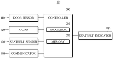
- FIG. 2 is a control block diagram illustrating a vehicle in some forms of the present disclosure.
- the vehicle 10 includes an engine, a transmission, a braking device, and a steering device.
- the engine may include a cylinder and a piston and may generate power for the vehicle 10 to travel.
- the transmission may include a plurality of gears and may transmit power generated by the engine to the wheels.
- the braking device may decelerate the vehicle 10 or stop the vehicle 10 through friction with the wheels.
- the steering device may change the travelling direction of the vehicle 10.
- the vehicle 10 may include a plurality of electrical components.
- the vehicle 10 may include an engine management system (EMS), a transmission controller (TCU), an electronic brake control module, an electronic power steering (EPS), a body control module (BCM), and a driver assistance system (DAS).
- EMS engine management system
- TCU transmission controller
- EPS electronic power steering
- BCM body control module
- DAS driver assistance system
- the BCM may control the operation of electronic components that provide convenience to the driver or ensure the safety of the driver.
- the BCM may control head lamps, wipers, clusters, multifunction switches, turn signal lamps, seat belts, and the like.
- Electronic components of the vehicle 10 may communicate with each other via a vehicle communication network (NT).
- NT vehicle communication network
- electronic components may transmit data through Ethernet, most oriented systems transport (MOST), Flexray, controller area network (CAN), local interconnect network (LIN), and the like.
- MOST most oriented systems transport
- CAN controller area network
- LIN local interconnect network
- a driver's seat 11, a passenger seat 12, and a rear seat 13 may be provided inside the vehicle 10.
- Each of the driver's seat 11, the passenger seat 12, and the rear seat 13 is provided with a seat belt. That is, the seat belt may be provided for each seat of the vehicle 10.
- the seat belt may be referred to as a safety belt. Since the seat belt is a basic configuration provided in the vehicle 10, detailed description thereof will be omitted.
- the vehicle 10 is provided at an inside thereof with a dashboard, a cluster 210, a steering wheel, a plurality of buttons related to various functions of the vehicle 10, an audio, video, navigation (AVN) device 220, a speaker 230, and the like.
- the cluster 210 may include various indicating lights.
- the cluster 210 may be implemented in a digital type cluster.
- the AVN device 220 includes a display.
- the AVN device 220 and the speaker 230 may be provided at various locations in the vehicle 10.
- a radar 120 is provided inside the vehicle 10 to acquire radar data regarding an object inside the vehicle 10.
- the radar 120 is illustrated as being installed on the ceiling of the vehicle 10 but may be installed at various locations.
- a plurality of the radars may be provided.
- the radar 120 includes a transmit antenna (or a transmit antenna array) that emits transmission radio waves and a receive antenna (or a receive antenna array) that receives reflected radio waves reflected from an object.
- the radar 120 may acquire radar data regarding an object inside the vehicle from the transmission radio waves transmitted by the transmit antenna and the reflected radio waves received by the receive antenna.
- the radar 120 may be connected to a controller 300 through the vehicle communication network NT, a hard wire, or a printed circuit board (PCB).
- the radar 120 may transmit radar data to the controller 300.
- an imaging sensor (not shown) may be provided inside the vehicle 10.
- the imaging sensor may photograph an occupant of the vehicle 10 to acquire an image of the occupant, and generate image data.
- the imaging sensor may be a camera.
- the imaging sensor may photograph a face and a gesture of a passenger who rides the vehicle 10.
- the imaging sensor may be electrically connected to the controller 300, and may transmit the image data to the controller 300.
- the vehicle 10 includes a door sensor 110 provided at a door, a seatbelt sensor 130 provided at a seat belt, and may include a seating sensor (not shown) provided at respective seats 11, 12, and 13.
- the sensors are not limited thereto, and various sensors may be further provided.
- the sensors may be electrically connected to the controller 300 and transmit sensing data to the controller 300.
- the door sensor 110 detects opening and closing of the door.
- the seatbelt sensor 130 may be provided on each seat belt of the seats, and may detect a state of the seat belt.
- the seatbelt sensor 130 detects an unfastened state or a fastened state of the seat belt.
- the vehicle 10 includes a seatbelt indicator 200.
- the seatbelt indicator 200 provides a notification regarding the fastening of the seat belt.
- the seatbelt indicator 200 may provide a notification regarding the fastening of each seat belt provided on each seat.
- the seatbelt indicator 200 may include at least one of an indicator light provided in the cluster 210, a graphic user interface output through the AVN device 220, and a warning sound output through the speaker 230.
- the seatbelt indicator 200 may include a guide message regarding the wearing of a seat belt output through at least one of the AVN device 220 or the speaker 230.
- the seatbelt indicator 200 may also be referred to as a seatbelt reminder.
- the vehicle 10 may further include a communicator 140.
- the communicator 140 may transmit and receive data by communicating with an external device.
- the communicator 140 may transmit notification information regarding the fastening of the seat belt to an external device.
- the controller 300 may control the communicator 140 to transmit notification information regarding the fastening of the seat belt to a smart phone of a driver, which is an external device.
- the communicator 140 may communicate with an external device using various methods.
- the communicator 140 may transmit and receive data to and from an external device using communication technologies, such as vehicle-to-vehicle (V2V) communication, Wi-Fi, wireless local area network (WLAN), ultra-mobile broadband (UMB), long term evolution (LTE), and the like.
- V2V vehicle-to-vehicle
- Wi-Fi wireless local area network
- WLAN wireless local area network
- UMB ultra-mobile broadband
- LTE long term evolution
- the present disclosure is not limited thereto, and any method may be applied as long as it may communicate with an external device.
- the controller 300 includes a memory 320 for memorizing/storing programs, instructions, and data for controlling the operation of the vehicle 10, and a processor for generating a control signal for controlling the operation of the vehicle 10 on the basis of the programs, instructions, and data memorized/stored in the memory 320.
- the processor 310 may include a digital processor for processing at least one of radar data, image data, or sensing data, and a micro control unit (MCU) for generating a control signal.
- the processor 310 and the memory 320 may be implemented as separate chips or as a single chip.
- the controller 300 may include a plurality of the processors 310 and a plurality of the memories 320.
- the processor 310 may include a logic circuit and an arithmetic circuit, may process data according to programs and/or instructions provided from the memory 320, and generate a control signal according to a processing result.
- the processor 310 may be electrically connected to various devices included in the vehicle 10.
- the processor 310 is electrically connected to the memory 320.
- the memory 320 may include a non-volatile memory, such as a flash memory, a read only memory (ROM), an erasable programmable read only memory (EPROM), or the like, as well as a volatile memory, such as an S-RAM or a D-RAM.
- the controller 300 performs a first check regarding the state of the seat belt.
- the first check regarding the state of the seat belt is performed before the vehicle 10 is occupied by an object. That is, the controller 300 may determine whether the seat belt is in an unfastened state or a fastened state before the vehicle 10 is occupied by an object.
- the controller 300 may process radar data.
- the controller 300 checks the occupancy and the occupied position of the object on the basis of the radar data acquired by the radar 120.
- the controller 300 identifies the type of the object in the vehicle on the basis of the radar data.
- the controller 300 identifies whether the object occupying the vehicle 10 is a human or an object other than a human.
- the controller 300 operates the radar 120 if the opening and closing of the door is detected by the door sensor 110.
- the controller 300 determines the operating state of the seatbelt indicator 200 on the basis of the type of the object and the occupied position of the object.
- the controller 300 determines the operating state of the seatbelt indicator 200 related to a seat belt provided in a seat corresponding to the occupied position of the object.
- the controller 300 determines the operating state of the seatbelt indicator 200 to have an off-state. Since the seat belt does not need to be fastened if the object is not a human, turning off the seatbelt indicator 200 may be desired in terms of user convenience.
- the controller 300 may turn on the seatbelt indicator after performing the first check regarding the state of the seat belt.
- the controller 300 turns on the seatbelt indicator if it is determined as a result of the first check that the seat belt is in an unfastened state.
- the controller 300 may turn on the seatbelt indicator even if the seat belt is already fastened before a passenger rides the vehicle, to provide a notification regarding wearing of the seat belt.
- controller 300 may turn on the seatbelt indicator if occupancy of the object is confirmed after the first check.
- the controller 300 performs a second check regarding the state of the seat belt if the type of the object is a human, and determines the operating state of the seatbelt indicator 200 to have an on-state or an off state according to the result of the second check.
- the controller 300 allows the operating state of the seatbelt indicator 200 to be kept in an on-state or to be switched into an off-state according to the result of the second check.
- the controller 300 may determine the operating state of the seatbelt indicator 200 to have an off-state. Since it is determined that the object, which is a human being, wears the seat belt, the seatbelt indicator 200 is turned off.
- the controller 300 may determine the operating state of the seatbelt indicator 200 to have an off-state. This is because it is determined that the object, which is a human, has loosened the seat belt, which was previously fastened, and then has worn the seat belt.
- the controller 300 may determine the operating state of the seatbelt indicator to have an on-state. This is because it is determined that the object, which is a human, does not wear the seat belt.
- the controller 300 may determine the operating state of the seatbelt indicator to have an on-state. This is because it is determined that the object, which is a human, has not unfastened and worn the seat belt.
- the vehicle 10 in some forms of the present disclosure may inhibit undesired notifications by turning on/off an operation of the seatbelt indicator according to the type of the object, and may secure passenger safety by allowing passengers to wear the seat belt.
- undesired notification of the seatbelt indicator may be prevented.
- undesired operations of the seatbelt indicator related to an object occupied in the rear seat may be eliminated.
- FIG. 3 is a flowchart showing a method of controlling a vehicle in some forms of the present disclosure.
- the door sensor 110 detects opening and closing of the door (501).
- the controller 300 operates the radar 120 provided inside the vehicle (502).
- the controller 300 performs the first check regarding the state of the seat belt (503). That is, the controller 300 may determine whether the seat belt is in an unfastened state or a fastened state before the vehicle 10 is occupied by an object.
- the controller 300 may turn on the seatbelt indicator after performing the first check regarding the state of the seat belt (504).
- the controller 300 may turn off the seatbelt indicator if it is determined as a result of the first check that the seat belt is in a fastened state.
- the controller 300 checks occupancy of an object on the basis of radar data obtained by the radar 120 (505).
- the controller 300 may turn on the seatbelt indicator if the occupancy of the object is confirmed after the first check.
- the controller 300 identifies the type of the object in the vehicle on the basis of the radar data (506). The controller 300 identifies whether the object in the vehicle 10 is a human or an object other than a human.
- the controller 300 determines the operating state of the seatbelt indicator 200 to have an off-state (507 and 511).
- the controller 300 performs the second check regarding the state of the seat belt (508). If it is determined as a result of the second check that the state of the seat belt is in an unfastened state, the controller 300 determines the operating state of the seatbelt indicator to have an on-state (509 and 510). If it is determined as a result of the second check that the state of the seat belt is in a fastened state, the controller 300 determines the operating state of the seatbelt indicator 200 to have an off-state (511).
- FIGS. 4 and 5 are detailed flowcharts showing a method of controlling a vehicle in some forms of the present disclosure.
- the controller 300 performs the first check regarding the state of the seat belt (601). If it is determined as a result of the first check that the state of the seat belt is in an unfastened state (602), the controller 300 turns on the seatbelt indicator (603). The controller 300 checks occupancy of a passenger (a human) (604), and performs the second check regarding the state of the seat belt (605). If it is determined as a result of the second check that the state of the seat belt is in an unfastened state (606), the controller 300 determines such that the operating state of the seatbelt indicator is kept in the on-state (607). This is because it is determined that the passenger does not wear a seat belt.
- the controller 300 turns off the seatbelt indicator 200 (608). Since it is determined that the passenger wears the seat belt, the seatbelt indicator 200 is turned off.
- the controller 300 performs the first check regarding the state of the seat belt (701). If it is determined as a result of the first check that the state of the seat belt is in a fastened state (702), the controller 300 turns on the seatbelt indicator (703). In this case, the controller 300 may turn off the seatbelt indicator. The controller 300 checks the occupancy of the passenger (a human) (704) and performs the second check regarding the state of the seat belt (705).
- the controller 300 determines the operating state of the seatbelt indicator to have an on-state (706 and 708). This is because it is determined that the passenger has not loosened the seat belt, which was previously fastened, and not worn the seat belt.
- the controller 300 determines the operating state of the seatbelt indicator 200 to have an off-state (706 and 707). This is because it is determined that the passenger has loosened the seat belt, which was previously fastened, and has worn the seat belt.
- the vehicle in some forms of the present disclosure and the method of controlling the same includes the radar provided in the vehicle, identify the type of the object in the vehicle using the radar, and determine the operating state of the seatbelt indicator according to the type of the object.
- the vehicle in some forms of the present disclosure and the method of controlling the same may eliminate an undesired notification by turning on/off the operation of the seatbelt indicator according to the type of object, and ensure the safety of the passenger by allowing the passenger to wear the seat belt.
Landscapes
- Engineering & Computer Science (AREA)
- Mechanical Engineering (AREA)
- Transportation (AREA)
- Automation & Control Theory (AREA)
- Chemical & Material Sciences (AREA)
- Combustion & Propulsion (AREA)
- Aviation & Aerospace Engineering (AREA)
- Physics & Mathematics (AREA)
- Electromagnetism (AREA)
- Automotive Seat Belt Assembly (AREA)
Description
- The present disclosure relates to a vehicle capable of appropriately providing a notification regarding seat belt wearing and a method of controlling the same.
- The statements in this section merely provide background information related to the present disclosure and may not constitute prior art.
- A method for recognizing a seat occupancy of seats in a motor vehicle is known, for example, from
US 2018/0222346 A1 . - Recently, wearing seat belts has been mandatory for the rear seat passengers by the laws strengthening the rear seat safety. Accordingly, technology of rear seat seatbelt reminder has been applied to vehicles. The conventional technology provides a notification regarding a seat belt for more than 60 seconds unconditionally when the vehicle is turned on. Such a conventional technology, which provide the notification regarding the seat belt regardless of whether the passenger rides the vehicle, may bother the driver. In addition, a vehicle provided with a seating sensor may determine that a person has boarded the vehicle when a heavy load is placed on the seat, and provides an undesired inappropriate seat belt notification.
- The present disclosure provides a vehicle capable of identifying the type of an object occupying the vehicle by using a radar provided in the vehicle and determining an operating state of a seat belt indicator according to the type of the object, and a method of controlling the same.
- The present disclosure also provides a vehicle capable of preventing an undesired inappropriate notification by turning on/off the operation of the seatbelt indicator according to the type of the object, and capable of ensuring the safety of the passenger by allowing the passengers to wear the seatbelt, and a method of controlling the same.
- Additional aspects of the disclosure will be set forth in part in the description which follows and, in part, will be obvious from the description, or may be learned by practice of the disclosure.
- The present invention provides a vehicle according to claim 1.
- The controller of the vehicle determines the operating state of the seatbelt indicator to have an off-state if the type of the object is not a human.
- The controller performs a second check regarding the state of the seatbelt if the type of the object is a human, and determines the operating state to have an on-state or an off-state depending on a result of the second check.
- The controller turns on the seatbelt indicator after performing the first check regarding the state of the seat belt, and maintains the operating state of the seatbelt indicator in an on-state or switches the operating state of the seatbelt indicator to an off-state.
- The controller may determine the operating state of the seat belt indicator to have an off-state if the state of the seat belt is determined to be in an unfasten state according to the first check and is determined to be in a fastened state according to the second check.
- The controller may determine the operating state of the seatbelt indicator to have an on-state if the state of the seat belt is determined to be in an unfasten state according to the first check and is determined to be in an unfastened state according to the second check.
- The controller may determine the operating state of the seat belt indicator to have an off-state if the state of the seat belt is determined to be in a fasten state according to the first check and is determined to be switched to an unfastened state and then to a fastened state according to the second check.
- The controller may determine the operating state of the seat belt indicator to have an on-state if the state of the seat belt is determined to be in a fasten state according to the first check and is determined to be kept according to the second check.
- The seatbelt indicator may include at least one of an indicator light provided in a cluster, a graphic user interface output through an audio, video, navigation (AVN) device, and a warning sound output through a speaker.
- Moreover, the present invention provides a method of controlling a vehicle according to claim 6.
- According to the method, the determining of the operating state of the seatbelt indicator includes determining the operating state of the seatbelt indicator to have an off-state if the type of the object is not a human.
- The determining of the operating state of the seatbelt indicator includes: performing a second check regarding the state of the seatbelt if the type of the object is a human; and determining the operating state to have an on-state or an off-state depending on a result of the second check.
- The method further includes turning on the seatbelt indicator after performing the first check regarding the state of the seat belt, wherein the determining of the operating state of the seatbelt indicator includes maintaining the operating state of the seatbelt indicator in an on-state or switching the operating state of the seatbelt indicator to an off-state. Further advantageous embodiments of the present invention are disclosed in the dependent claims.
- The determining of the operating state of the seatbelt indicator may include determining the operating state of the seat belt indicator to have an off-state if the state of the seat belt is determined to be in an unfasten state according to the first check and is determined to be in a fastened state according to the second check.
- The determining of the operating state of the seatbelt indicator may include determining the operating state of the seatbelt indicator to have an on-state if the state of the seat belt is determined to be in an unfasten state according to the first check and is determined to be in an unfastened state according to the second check.
- The determining of the operating state of the seatbelt indicator may include determining the operating state of the seat belt indicator to have an off-state if the state of the seat belt is determined to be in a fasten state according to the first check and is determined to be switched to an unfastened state and then to a fastened state according to the second check.
- The determining of the operating state of the seatbelt indicator may include determining the operating state of the seat belt indicator to have an on-state if the state of the seat belt is determined to be in a fasten state according to the first check and is determined to be kept according to the second check.
- The seatbelt indicator may include at least one of an indicator light provided in a cluster, a graphic user interface output through an audio, video, navigation (AVN) device, and a warning sound output through a speaker.
- Further areas of applicability will become apparent from the description provided herein. It should be understood that the description and specific examples are intended for purposes of illustration only and are not intended to limit the scope of the present disclosure.
- In order that the disclosure may be well understood, there will now be described various forms thereof, given by way of example, reference being made to the accompanying drawings, in which:
-
FIG. 1 is a view illustrating an interior of a vehicle in one form of the present disclosure; -
FIG. 2 is a control block diagram illustrating a vehicle in one form of the present disclosure; -
FIG. 3 is a flowchart showing a method of controlling a vehicle in one form of the present disclosure; and -
FIGS. 4 and5 are detailed flowcharts showing a method of controlling a vehicle in one form of the present disclosure. - The drawings described herein are for illustration purposes only and are not intended to limit the scope of the present disclosure in any way.
- The following description is merely exemplary in nature and is not intended to limit the present disclosure, application, or uses. It should be understood that throughout the drawings, corresponding reference numerals indicate like or corresponding parts and features.
- Hereinafter, a vehicle and a method of controlling the same in some forms of the present disclosure will be described with reference to the accompanying drawings.
-
FIG. 1 is a view illustrating an interior of avehicle 10 in some forms of the present disclosure.FIG. 2 is a control block diagram illustrating a vehicle in some forms of the present disclosure. - The
vehicle 10 includes an engine, a transmission, a braking device, and a steering device. The engine may include a cylinder and a piston and may generate power for thevehicle 10 to travel. The transmission may include a plurality of gears and may transmit power generated by the engine to the wheels. The braking device may decelerate thevehicle 10 or stop thevehicle 10 through friction with the wheels. The steering device may change the travelling direction of thevehicle 10. - The
vehicle 10 may include a plurality of electrical components. For example, thevehicle 10 may include an engine management system (EMS), a transmission controller (TCU), an electronic brake control module, an electronic power steering (EPS), a body control module (BCM), and a driver assistance system (DAS). - In particular, the BCM may control the operation of electronic components that provide convenience to the driver or ensure the safety of the driver. For example, the BCM may control head lamps, wipers, clusters, multifunction switches, turn signal lamps, seat belts, and the like.
- Electronic components of the
vehicle 10 may communicate with each other via a vehicle communication network (NT). For example, electronic components may transmit data through Ethernet, most oriented systems transport (MOST), Flexray, controller area network (CAN), local interconnect network (LIN), and the like. - Referring to
FIGS. 1 and2 , a driver'sseat 11, apassenger seat 12, and arear seat 13 may be provided inside thevehicle 10. Each of the driver'sseat 11, thepassenger seat 12, and therear seat 13 is provided with a seat belt. That is, the seat belt may be provided for each seat of thevehicle 10. The seat belt may be referred to as a safety belt. Since the seat belt is a basic configuration provided in thevehicle 10, detailed description thereof will be omitted. - The
vehicle 10 is provided at an inside thereof with a dashboard, acluster 210, a steering wheel, a plurality of buttons related to various functions of thevehicle 10, an audio, video, navigation (AVN)device 220, aspeaker 230, and the like. Thecluster 210 may include various indicating lights. Thecluster 210 may be implemented in a digital type cluster. TheAVN device 220 includes a display. TheAVN device 220 and thespeaker 230 may be provided at various locations in thevehicle 10. - In addition, a
radar 120 is provided inside thevehicle 10 to acquire radar data regarding an object inside thevehicle 10. InFIG. 2 , theradar 120 is illustrated as being installed on the ceiling of thevehicle 10 but may be installed at various locations. In addition, a plurality of the radars may be provided. - The
radar 120 includes a transmit antenna (or a transmit antenna array) that emits transmission radio waves and a receive antenna (or a receive antenna array) that receives reflected radio waves reflected from an object. Theradar 120 may acquire radar data regarding an object inside the vehicle from the transmission radio waves transmitted by the transmit antenna and the reflected radio waves received by the receive antenna. Theradar 120 may be connected to acontroller 300 through the vehicle communication network NT, a hard wire, or a printed circuit board (PCB). Theradar 120 may transmit radar data to thecontroller 300. - Although not shown, an imaging sensor (not shown) may be provided inside the
vehicle 10. The imaging sensor may photograph an occupant of thevehicle 10 to acquire an image of the occupant, and generate image data. The imaging sensor may be a camera. The imaging sensor may photograph a face and a gesture of a passenger who rides thevehicle 10. The imaging sensor may be electrically connected to thecontroller 300, and may transmit the image data to thecontroller 300. - Various sensors may be provided in the
vehicle 10. The sensors may be installed at various locations in thevehicle 10. For example, thevehicle 10 includes adoor sensor 110 provided at a door, aseatbelt sensor 130 provided at a seat belt, and may include a seating sensor (not shown) provided atrespective seats controller 300 and transmit sensing data to thecontroller 300. - The
door sensor 110 detects opening and closing of the door. Theseatbelt sensor 130 may be provided on each seat belt of the seats, and may detect a state of the seat belt. Theseatbelt sensor 130 detects an unfastened state or a fastened state of the seat belt. - The
vehicle 10 includes aseatbelt indicator 200. Theseatbelt indicator 200 provides a notification regarding the fastening of the seat belt. Theseatbelt indicator 200 may provide a notification regarding the fastening of each seat belt provided on each seat. Theseatbelt indicator 200 may include at least one of an indicator light provided in thecluster 210, a graphic user interface output through theAVN device 220, and a warning sound output through thespeaker 230. In addition, theseatbelt indicator 200 may include a guide message regarding the wearing of a seat belt output through at least one of theAVN device 220 or thespeaker 230. Theseatbelt indicator 200 may also be referred to as a seatbelt reminder. - The
vehicle 10 may further include acommunicator 140. Thecommunicator 140 may transmit and receive data by communicating with an external device. In detail, thecommunicator 140 may transmit notification information regarding the fastening of the seat belt to an external device. For example, thecontroller 300 may control thecommunicator 140 to transmit notification information regarding the fastening of the seat belt to a smart phone of a driver, which is an external device. - The
communicator 140 may communicate with an external device using various methods. Thecommunicator 140 may transmit and receive data to and from an external device using communication technologies, such as vehicle-to-vehicle (V2V) communication, Wi-Fi, wireless local area network (WLAN), ultra-mobile broadband (UMB), long term evolution (LTE), and the like. The present disclosure is not limited thereto, and any method may be applied as long as it may communicate with an external device. - The
controller 300 includes amemory 320 for memorizing/storing programs, instructions, and data for controlling the operation of thevehicle 10, and a processor for generating a control signal for controlling the operation of thevehicle 10 on the basis of the programs, instructions, and data memorized/stored in thememory 320. Theprocessor 310 may include a digital processor for processing at least one of radar data, image data, or sensing data, and a micro control unit (MCU) for generating a control signal. Theprocessor 310 and thememory 320 may be implemented as separate chips or as a single chip. In addition, thecontroller 300 may include a plurality of theprocessors 310 and a plurality of thememories 320. - The
processor 310 may include a logic circuit and an arithmetic circuit, may process data according to programs and/or instructions provided from thememory 320, and generate a control signal according to a processing result. Theprocessor 310 may be electrically connected to various devices included in thevehicle 10. In addition, theprocessor 310 is electrically connected to thememory 320. Thememory 320 may include a non-volatile memory, such as a flash memory, a read only memory (ROM), an erasable programmable read only memory (EPROM), or the like, as well as a volatile memory, such as an S-RAM or a D-RAM. - Hereinafter, the operation of the
controller 300 for controlling the operation of the seatbelt indicator will be described in detail. - The
controller 300 performs a first check regarding the state of the seat belt. The first check regarding the state of the seat belt is performed before thevehicle 10 is occupied by an object. That is, thecontroller 300 may determine whether the seat belt is in an unfastened state or a fastened state before thevehicle 10 is occupied by an object. - The
controller 300 may process radar data. Thecontroller 300 checks the occupancy and the occupied position of the object on the basis of the radar data acquired by theradar 120. In addition, thecontroller 300 identifies the type of the object in the vehicle on the basis of the radar data. Thecontroller 300 identifies whether the object occupying thevehicle 10 is a human or an object other than a human. - The
controller 300 operates theradar 120 if the opening and closing of the door is detected by thedoor sensor 110. - The
controller 300 determines the operating state of theseatbelt indicator 200 on the basis of the type of the object and the occupied position of the object. Thecontroller 300 determines the operating state of theseatbelt indicator 200 related to a seat belt provided in a seat corresponding to the occupied position of the object. In detail, if the type of the object is not a human, thecontroller 300 determines the operating state of theseatbelt indicator 200 to have an off-state. Since the seat belt does not need to be fastened if the object is not a human, turning off theseatbelt indicator 200 may be desired in terms of user convenience. - The
controller 300 may turn on the seatbelt indicator after performing the first check regarding the state of the seat belt. Thecontroller 300 turns on the seatbelt indicator if it is determined as a result of the first check that the seat belt is in an unfastened state. Thecontroller 300 may turn on the seatbelt indicator even if the seat belt is already fastened before a passenger rides the vehicle, to provide a notification regarding wearing of the seat belt. - In addition, the
controller 300 may turn on the seatbelt indicator if occupancy of the object is confirmed after the first check. - The
controller 300 performs a second check regarding the state of the seat belt if the type of the object is a human, and determines the operating state of theseatbelt indicator 200 to have an on-state or an off state according to the result of the second check. - In detail, if the
seatbelt indicator 200 is in an on-state after the first check regarding the state of the seat belt is performed, thecontroller 300 allows the operating state of theseatbelt indicator 200 to be kept in an on-state or to be switched into an off-state according to the result of the second check. - If it is determined as the first check that the state of the seat belt is in an unfastened state, and it is determined as a result of the second check that the state of the seat belt is in a fastened state, the
controller 300 may determine the operating state of theseatbelt indicator 200 to have an off-state. Since it is determined that the object, which is a human being, wears the seat belt, theseatbelt indicator 200 is turned off. - If it is determined as a result of the first check that the state of the seat belt is determined to be in a fastened state, and it is determined as a result of the second check that the state of the seat belt is switched to an unfastened state and then to a fastened state, the
controller 300 may determine the operating state of theseatbelt indicator 200 to have an off-state. This is because it is determined that the object, which is a human, has loosened the seat belt, which was previously fastened, and then has worn the seat belt. - If it is determined as a result of the first check that the state of the seat belt is in an unfastened state, and it is determined as a result of the second check that the state of the seat belt is in an unfastened state, the
controller 300 may determine the operating state of the seatbelt indicator to have an on-state. This is because it is determined that the object, which is a human, does not wear the seat belt. - In addition, if it is determined as a result of the first check that the state of the seat belt is in a fastened state and it is determined as a result of the second check that the state of the seat belt is not switched, the
controller 300 may determine the operating state of the seatbelt indicator to have an on-state. This is because it is determined that the object, which is a human, has not unfastened and worn the seat belt. - As such, the
vehicle 10 in some forms of the present disclosure may inhibit undesired notifications by turning on/off an operation of the seatbelt indicator according to the type of the object, and may secure passenger safety by allowing passengers to wear the seat belt. In other words, by checking the state of the seat belt twice (the first check and the second check), undesired notification of the seatbelt indicator may be prevented. In particular, undesired operations of the seatbelt indicator related to an object occupied in the rear seat may be eliminated. -
FIG. 3 is a flowchart showing a method of controlling a vehicle in some forms of the present disclosure. - Referring to
FIG. 3 , thedoor sensor 110 detects opening and closing of the door (501). Thecontroller 300 operates theradar 120 provided inside the vehicle (502). Thecontroller 300 performs the first check regarding the state of the seat belt (503). That is, thecontroller 300 may determine whether the seat belt is in an unfastened state or a fastened state before thevehicle 10 is occupied by an object. Thecontroller 300 may turn on the seatbelt indicator after performing the first check regarding the state of the seat belt (504). Thecontroller 300 may turn off the seatbelt indicator if it is determined as a result of the first check that the seat belt is in a fastened state. - The
controller 300 checks occupancy of an object on the basis of radar data obtained by the radar 120 (505). Thecontroller 300 may turn on the seatbelt indicator if the occupancy of the object is confirmed after the first check. - The
controller 300 identifies the type of the object in the vehicle on the basis of the radar data (506). Thecontroller 300 identifies whether the object in thevehicle 10 is a human or an object other than a human. - If the type of the object is not a human, the
controller 300 determines the operating state of theseatbelt indicator 200 to have an off-state (507 and 511). - If the type of the object is a human, the
controller 300 performs the second check regarding the state of the seat belt (508). If it is determined as a result of the second check that the state of the seat belt is in an unfastened state, thecontroller 300 determines the operating state of the seatbelt indicator to have an on-state (509 and 510). If it is determined as a result of the second check that the state of the seat belt is in a fastened state, thecontroller 300 determines the operating state of theseatbelt indicator 200 to have an off-state (511). -
FIGS. 4 and5 are detailed flowcharts showing a method of controlling a vehicle in some forms of the present disclosure. - Referring to
FIG. 4 , thecontroller 300 performs the first check regarding the state of the seat belt (601). If it is determined as a result of the first check that the state of the seat belt is in an unfastened state (602), thecontroller 300 turns on the seatbelt indicator (603). Thecontroller 300 checks occupancy of a passenger (a human) (604), and performs the second check regarding the state of the seat belt (605). If it is determined as a result of the second check that the state of the seat belt is in an unfastened state (606), thecontroller 300 determines such that the operating state of the seatbelt indicator is kept in the on-state (607). This is because it is determined that the passenger does not wear a seat belt. - On the contrary, if it is determined as a result of the second check that the state of the seat belt is in a fastened state (606), the
controller 300 turns off the seatbelt indicator 200 (608). Since it is determined that the passenger wears the seat belt, theseatbelt indicator 200 is turned off. - Referring to
FIG. 5 , thecontroller 300 performs the first check regarding the state of the seat belt (701). If it is determined as a result of the first check that the state of the seat belt is in a fastened state (702), thecontroller 300 turns on the seatbelt indicator (703). In this case, thecontroller 300 may turn off the seatbelt indicator. Thecontroller 300 checks the occupancy of the passenger (a human) (704) and performs the second check regarding the state of the seat belt (705). - If it is determined as a result of the second check that the state of the seat belt is not switched, the
controller 300 determines the operating state of the seatbelt indicator to have an on-state (706 and 708). This is because it is determined that the passenger has not loosened the seat belt, which was previously fastened, and not worn the seat belt. - On the contrary, if it determined as a result of the second check that the state of the seat belt is switched to the unfastened state and then to the fastened state, the
controller 300 determines the operating state of theseatbelt indicator 200 to have an off-state (706 and 707). This is because it is determined that the passenger has loosened the seat belt, which was previously fastened, and has worn the seat belt. - As described above, the vehicle in some forms of the present disclosure and the method of controlling the same includes the radar provided in the vehicle, identify the type of the object in the vehicle using the radar, and determine the operating state of the seatbelt indicator according to the type of the object.
- In addition, the vehicle in some forms of the present disclosure and the method of controlling the same may eliminate an undesired notification by turning on/off the operation of the seatbelt indicator according to the type of object, and ensure the safety of the passenger by allowing the passenger to wear the seat belt.
Claims (9)
- A vehicle (10) comprising:a door sensor (110) configured to detect opening and closing of a door;a radar (120) provided in the vehicle (10) and configured to acquire radar data regarding an object in the vehicle (10);a seatbelt sensor (130) configured to detect a state of a seat belt provided on each seat of the vehicle (10);a seatbelt indicator (200) configured to provide a notification regarding fastening of the seat belt; anda controller (300) configured, in the following order to:control the radar (120) in response to the opening and the closing of the door;perform a first check regarding the state of the seatbelt;determine an operating state of the seatbelt indicator (200) to have an on-state if the seatbelt in an unfastened state;check an occupancy and an occupied position of the object based on the radar data;identify a type of the object in the vehicle (10) based on the radar data; determine the operating state of the seatbelt indicator (200) based on the type of the object and the occupied position of the object, wherein it is determined that the operating state of the seatbelt indicator (200) is an off-state when the type of the object is not a human, wherein, when the type of the object is a human, perform a second check regarding the state of the seatbelt; and maintain the operating state of the seatbelt indicator (200) in the on-state or switch the operating state of the seatbelt indicator (200) to the off-state depending on a result of the second check.
- The vehicle (10) of claim 1, wherein the controller (300) is configured to:
determine that the operating state of the seat belt indicator (200) is an off-state when the state of the seat belt is determined to be in an unfasten state based on the first check and the state of the seat belt is determined to be in a fastened state based on the second check. - The vehicle (10) of claim 1, wherein the controller (300) is configured to:
determine that the operating state of the seatbelt indicator (200) is an on-state when the state of the seat belt is determined to be in an unfasten state based on the first check and the state of the seat belt is determined to be in an unfastened state based on the second check. - The vehicle (10) of claim 1, wherein the controller (300) is configured to:
determine that the operating state of the seat belt indicator (200) is an off-state when the state of the seat belt is determined to be in a fasten state based on the first check and the state of the seat belt is determined to be switched to an unfastened state and then to a fastened state based on the second check. - The vehicle (10) of claim 1, wherein the controller (300) is configured to:
determine that the operating state of the seat belt indicator (200) is an on-state when the state of the seat belt is determined to be in a fasten state based on the first check and the state of the seat belt is determined to be maintained based on the second check. - A method of controlling a vehicle (10) comprising:detecting, by a door sensor (110), opening and closing of a door;when the opening and closing of the door is detected, acquiring, by a radar (120) provided in the vehicle, radar data regarding an object in the vehicle (10);performing, by a controller (300), a first check regarding a state of a seat belt provided on each seat of the vehicle (10);determining, by the controller (300), an operating state of the seatbelt indicator (200) to have an on-state if the seatbelt in an unfastened state;checking, by the controller (300), an occupancy and an occupied position of the object based on the radar data;identifying, by the controller (300), a type of the object in the vehicle (10) based on the radar data;determining, by the controller (300), an operating state of the seatbelt indicator(200) based on the type of the object and the occupied position of the object, wherein it is determined that the operating state of the seatbelt indicator (200) is an off-state when the type of the object is not a human, wherein, when the type of the object is a human, performing a second check regarding the state of the seatbelt; and maintaining, by the controller (300), the operating state of the seatbelt indicator (200) in the on-state or switching, by the controller (300), the operating state of the seatbelt indicator (200) to the off-state depending on a result of the second check.
- The method of claim 6, wherein determining the operating state of the seatbelt indicator (200) further comprises:
when the state of the seat belt is determined to be in an unfasten state based on the first check and the state of the seat belt is determined to be in a fastened state based on the second check, determining that the operating state of the seat belt indicator (200) is an off-state. - The method of claim 6, wherein determining the operating state of the seatbelt indicator (200) further comprises:
when the state of the seat belt is determined to be in an unfasten state based on the first check and the state of the seat belt is determined to be in an unfastened state based on the second check, determining that the operating state of the seatbelt indicator (200) is an on-state. - The method of claim 6, wherein determining the operating state of the seatbelt indicator (200) further comprises:
when the state of the seat belt is determined to be in a fasten state based on the first check and the state of the seat belt is determined to be switched to an unfastened state and then to a fastened state based on the second check, determining that the operating state of the seat belt indicator (200) is an off-state.
Applications Claiming Priority (1)
| Application Number | Priority Date | Filing Date | Title |
|---|---|---|---|
| KR1020190114191A KR102789190B1 (en) | 2019-09-17 | 2019-09-17 | Vehicle and control method for the same |
Publications (2)
| Publication Number | Publication Date |
|---|---|
| EP3795430A1 EP3795430A1 (en) | 2021-03-24 |
| EP3795430B1 true EP3795430B1 (en) | 2022-03-09 |
Family
ID=69167695
Family Applications (1)
| Application Number | Title | Priority Date | Filing Date |
|---|---|---|---|
| EP20151686.1A Active EP3795430B1 (en) | 2019-09-17 | 2020-01-14 | Vehicle with seat belt fastening indicator |
Country Status (3)
| Country | Link |
|---|---|
| US (1) | US11254284B2 (en) |
| EP (1) | EP3795430B1 (en) |
| KR (1) | KR102789190B1 (en) |
Families Citing this family (10)
| Publication number | Priority date | Publication date | Assignee | Title |
|---|---|---|---|---|
| US12141432B2 (en) * | 2009-07-02 | 2024-11-12 | Uusi, Llc | Vehicle occupant detection system |
| KR102762479B1 (en) * | 2019-11-26 | 2025-02-03 | 엘지전자 주식회사 | Apparatus and method for controlling interior of vehicle |
| DE112021006950T5 (en) * | 2021-01-29 | 2023-11-16 | Mitsubishi Electric Corporation | Radio wave sensor and occupant detection device |
| JP7312971B2 (en) * | 2021-03-30 | 2023-07-24 | パナソニックIpマネジメント株式会社 | vehicle display |
| US11687155B2 (en) * | 2021-05-13 | 2023-06-27 | Toyota Research Institute, Inc. | Method for vehicle eye tracking system |
| CN113200014A (en) * | 2021-05-21 | 2021-08-03 | 上汽通用五菱汽车股份有限公司 | Seat belt prompting method, vehicle and readable storage medium |
| US12576789B2 (en) * | 2022-08-12 | 2026-03-17 | Ford Global Technologies, Llc | Cargo orientation and alignment |
| US11995491B1 (en) | 2023-01-19 | 2024-05-28 | Ford Global Technologies, Llc | Control of vehicle with door detached |
| FR3159392B1 (en) | 2024-02-16 | 2026-01-09 | Arkema France | Composition based on poly(vinylidene fluoride) |
| FR3159391A1 (en) | 2024-02-16 | 2025-08-22 | Arkema France | Composition based on poly(vinylidene fluoride) |
Family Cites Families (11)
| Publication number | Priority date | Publication date | Assignee | Title |
|---|---|---|---|---|
| CA2492006C (en) * | 2004-01-20 | 2008-05-06 | Faurecia Automotive Seating Canada Limited | Vehicle seatbelt usage sensing apparatus and method for generating and transmitting a seatbelt warning signal |
| JP2008129948A (en) * | 2006-11-22 | 2008-06-05 | Takata Corp | Occupant detection device, actuator control system, seat belt system, vehicle |
| US7813856B2 (en) * | 2007-10-03 | 2010-10-12 | Gm Global Technology Operations, Inc. | Vehicular seatbelt monitoring system and process |
| EP2839997B1 (en) * | 2013-08-19 | 2016-10-19 | Volvo Car Corporation | Arrangement for control of vehicle seat belt alert arrangement, a seat, a vehicle, a method and use of the arrangement |
| US9676356B2 (en) * | 2014-03-10 | 2017-06-13 | Ford Global Technologies Llc | System and method for seatbelt use monitoring |
| US9365186B2 (en) * | 2014-08-17 | 2016-06-14 | Toyota Motor Engineering & Manufacturing North America, Inc. | Advanced seatbelt interlock using video recognition |
| JP2016199207A (en) * | 2015-04-14 | 2016-12-01 | 株式会社東海理化電機製作所 | Seat belt warning device |
| LU93324B1 (en) * | 2016-11-25 | 2018-05-25 | Iee Sa | Polarimetric Radar System and Method for Detecting and Classifying Vehicle Occupants and Other Objects in a Vehicle Interior |
| DE102017201965B4 (en) * | 2017-02-08 | 2025-03-06 | Robert Bosch Gmbh | Procedure for detecting seat occupancy |
| US11479147B2 (en) * | 2017-07-31 | 2022-10-25 | Ford Global Technologies, Llc | Vehicle occupancy management systems and methods |
| JP2021530069A (en) * | 2018-06-26 | 2021-11-04 | カッツ,イテイ | Situational driver monitoring system |
-
2019
- 2019-09-17 KR KR1020190114191A patent/KR102789190B1/en active Active
-
2020
- 2020-01-14 EP EP20151686.1A patent/EP3795430B1/en active Active
- 2020-01-15 US US16/743,901 patent/US11254284B2/en active Active
Also Published As
| Publication number | Publication date |
|---|---|
| US20210078529A1 (en) | 2021-03-18 |
| US11254284B2 (en) | 2022-02-22 |
| EP3795430A1 (en) | 2021-03-24 |
| KR20210032766A (en) | 2021-03-25 |
| KR102789190B1 (en) | 2025-04-01 |
Similar Documents
| Publication | Publication Date | Title |
|---|---|---|
| EP3795430B1 (en) | Vehicle with seat belt fastening indicator | |
| EP1947548B1 (en) | Actuation system for functions in a vehicle and vehicle | |
| JP2020078959A (en) | Alighting assistance device | |
| US12145596B2 (en) | Cabin-inside detection device and cabin-inside detection method | |
| EP3255868A1 (en) | Methods, systems, and vehicles for disabling a function of one or more mobile devices within a passenger cabin of a vehicle | |
| US9981598B2 (en) | Alighting notification device | |
| US10773683B1 (en) | Occupant seatbelt status | |
| CN114174141B (en) | vehicle control system | |
| SE543675C2 (en) | Method and device for activating an unoccupied vehicle seat in case of imminent collision | |
| CN111093130B (en) | Information processing apparatus and information processing method | |
| JP7322536B2 (en) | Mobile body control device | |
| JP6963940B2 (en) | Driving assistance devices, driving assistance methods, and programs | |
| US12434731B2 (en) | Vehicle driver or occupant health and alertness monitoring and assistance system | |
| US20190275888A1 (en) | Methods and systems for providing visual notifications in the peripheral vision of a driver | |
| US11700522B2 (en) | Vehicle that has automatic notification function | |
| US10583780B1 (en) | Vehicle collision warning system and method | |
| CN107920407B (en) | Intelligent get-off lighting system | |
| US11348346B2 (en) | Control apparatus | |
| US12522163B2 (en) | Method for function control on a vehicle under consideration of a detected level of attention of a person in an interior of the vehicle | |
| EP2815930B1 (en) | Arrangement, vehicle and method for control of vehicle-airbag-status display | |
| JP2022161097A (en) | Control device for vehicle | |
| JP2018069862A (en) | Electronic mirror device | |
| EP4454939B1 (en) | Method of facilitating occupant safety in an autonomous vehicle and a vehicle occupant safety system | |
| JP7609277B2 (en) | Driver's face recognition device and face recognition program | |
| JP2025099983A (en) | notification device |
Legal Events
| Date | Code | Title | Description |
|---|---|---|---|
| PUAI | Public reference made under article 153(3) epc to a published international application that has entered the european phase |
Free format text: ORIGINAL CODE: 0009012 |
|
| STAA | Information on the status of an ep patent application or granted ep patent |
Free format text: STATUS: REQUEST FOR EXAMINATION WAS MADE |
|
| 17P | Request for examination filed |
Effective date: 20201224 |
|
| AK | Designated contracting states |
Kind code of ref document: A1 Designated state(s): AL AT BE BG CH CY CZ DE DK EE ES FI FR GB GR HR HU IE IS IT LI LT LU LV MC MK MT NL NO PL PT RO RS SE SI SK SM TR |
|
| AX | Request for extension of the european patent |
Extension state: BA ME |
|
| RAP3 | Party data changed (applicant data changed or rights of an application transferred) |
Owner name: HYUNDAI MOTOR COMPANY Owner name: KIA CORPORATION |
|
| GRAP | Despatch of communication of intention to grant a patent |
Free format text: ORIGINAL CODE: EPIDOSNIGR1 |
|
| STAA | Information on the status of an ep patent application or granted ep patent |
Free format text: STATUS: GRANT OF PATENT IS INTENDED |
|
| INTG | Intention to grant announced |
Effective date: 20210927 |
|
| GRAS | Grant fee paid |
Free format text: ORIGINAL CODE: EPIDOSNIGR3 |
|
| GRAA | (expected) grant |
Free format text: ORIGINAL CODE: 0009210 |
|
| STAA | Information on the status of an ep patent application or granted ep patent |
Free format text: STATUS: THE PATENT HAS BEEN GRANTED |
|
| AK | Designated contracting states |
Kind code of ref document: B1 Designated state(s): AL AT BE BG CH CY CZ DE DK EE ES FI FR GB GR HR HU IE IS IT LI LT LU LV MC MK MT NL NO PL PT RO RS SE SI SK SM TR |
|
| REG | Reference to a national code |
Ref country code: CH Ref legal event code: EP Ref country code: AT Ref legal event code: REF Ref document number: 1473897 Country of ref document: AT Kind code of ref document: T Effective date: 20220315 |
|
| REG | Reference to a national code |
Ref country code: DE Ref legal event code: R096 Ref document number: 602020002072 Country of ref document: DE |
|
| REG | Reference to a national code |
Ref country code: IE Ref legal event code: FG4D |
|
| REG | Reference to a national code |
Ref country code: LT Ref legal event code: MG9D |
|
| REG | Reference to a national code |
Ref country code: NL Ref legal event code: MP Effective date: 20220309 |
|
| PG25 | Lapsed in a contracting state [announced via postgrant information from national office to epo] |
Ref country code: SE Free format text: LAPSE BECAUSE OF FAILURE TO SUBMIT A TRANSLATION OF THE DESCRIPTION OR TO PAY THE FEE WITHIN THE PRESCRIBED TIME-LIMIT Effective date: 20220309 Ref country code: RS Free format text: LAPSE BECAUSE OF FAILURE TO SUBMIT A TRANSLATION OF THE DESCRIPTION OR TO PAY THE FEE WITHIN THE PRESCRIBED TIME-LIMIT Effective date: 20220309 Ref country code: NO Free format text: LAPSE BECAUSE OF FAILURE TO SUBMIT A TRANSLATION OF THE DESCRIPTION OR TO PAY THE FEE WITHIN THE PRESCRIBED TIME-LIMIT Effective date: 20220609 Ref country code: LT Free format text: LAPSE BECAUSE OF FAILURE TO SUBMIT A TRANSLATION OF THE DESCRIPTION OR TO PAY THE FEE WITHIN THE PRESCRIBED TIME-LIMIT Effective date: 20220309 Ref country code: HR Free format text: LAPSE BECAUSE OF FAILURE TO SUBMIT A TRANSLATION OF THE DESCRIPTION OR TO PAY THE FEE WITHIN THE PRESCRIBED TIME-LIMIT Effective date: 20220309 Ref country code: BG Free format text: LAPSE BECAUSE OF FAILURE TO SUBMIT A TRANSLATION OF THE DESCRIPTION OR TO PAY THE FEE WITHIN THE PRESCRIBED TIME-LIMIT Effective date: 20220609 |
|
| REG | Reference to a national code |
Ref country code: AT Ref legal event code: MK05 Ref document number: 1473897 Country of ref document: AT Kind code of ref document: T Effective date: 20220309 |
|
| PG25 | Lapsed in a contracting state [announced via postgrant information from national office to epo] |
Ref country code: LV Free format text: LAPSE BECAUSE OF FAILURE TO SUBMIT A TRANSLATION OF THE DESCRIPTION OR TO PAY THE FEE WITHIN THE PRESCRIBED TIME-LIMIT Effective date: 20220309 Ref country code: GR Free format text: LAPSE BECAUSE OF FAILURE TO SUBMIT A TRANSLATION OF THE DESCRIPTION OR TO PAY THE FEE WITHIN THE PRESCRIBED TIME-LIMIT Effective date: 20220610 Ref country code: FI Free format text: LAPSE BECAUSE OF FAILURE TO SUBMIT A TRANSLATION OF THE DESCRIPTION OR TO PAY THE FEE WITHIN THE PRESCRIBED TIME-LIMIT Effective date: 20220309 |
|
| PG25 | Lapsed in a contracting state [announced via postgrant information from national office to epo] |
Ref country code: NL Free format text: LAPSE BECAUSE OF FAILURE TO SUBMIT A TRANSLATION OF THE DESCRIPTION OR TO PAY THE FEE WITHIN THE PRESCRIBED TIME-LIMIT Effective date: 20220309 |
|
| PG25 | Lapsed in a contracting state [announced via postgrant information from national office to epo] |
Ref country code: SM Free format text: LAPSE BECAUSE OF FAILURE TO SUBMIT A TRANSLATION OF THE DESCRIPTION OR TO PAY THE FEE WITHIN THE PRESCRIBED TIME-LIMIT Effective date: 20220309 Ref country code: SK Free format text: LAPSE BECAUSE OF FAILURE TO SUBMIT A TRANSLATION OF THE DESCRIPTION OR TO PAY THE FEE WITHIN THE PRESCRIBED TIME-LIMIT Effective date: 20220309 Ref country code: RO Free format text: LAPSE BECAUSE OF FAILURE TO SUBMIT A TRANSLATION OF THE DESCRIPTION OR TO PAY THE FEE WITHIN THE PRESCRIBED TIME-LIMIT Effective date: 20220309 Ref country code: PT Free format text: LAPSE BECAUSE OF FAILURE TO SUBMIT A TRANSLATION OF THE DESCRIPTION OR TO PAY THE FEE WITHIN THE PRESCRIBED TIME-LIMIT Effective date: 20220711 Ref country code: ES Free format text: LAPSE BECAUSE OF FAILURE TO SUBMIT A TRANSLATION OF THE DESCRIPTION OR TO PAY THE FEE WITHIN THE PRESCRIBED TIME-LIMIT Effective date: 20220309 Ref country code: EE Free format text: LAPSE BECAUSE OF FAILURE TO SUBMIT A TRANSLATION OF THE DESCRIPTION OR TO PAY THE FEE WITHIN THE PRESCRIBED TIME-LIMIT Effective date: 20220309 Ref country code: CZ Free format text: LAPSE BECAUSE OF FAILURE TO SUBMIT A TRANSLATION OF THE DESCRIPTION OR TO PAY THE FEE WITHIN THE PRESCRIBED TIME-LIMIT Effective date: 20220309 Ref country code: AT Free format text: LAPSE BECAUSE OF FAILURE TO SUBMIT A TRANSLATION OF THE DESCRIPTION OR TO PAY THE FEE WITHIN THE PRESCRIBED TIME-LIMIT Effective date: 20220309 |
|
| PG25 | Lapsed in a contracting state [announced via postgrant information from national office to epo] |
Ref country code: PL Free format text: LAPSE BECAUSE OF FAILURE TO SUBMIT A TRANSLATION OF THE DESCRIPTION OR TO PAY THE FEE WITHIN THE PRESCRIBED TIME-LIMIT Effective date: 20220309 Ref country code: IS Free format text: LAPSE BECAUSE OF FAILURE TO SUBMIT A TRANSLATION OF THE DESCRIPTION OR TO PAY THE FEE WITHIN THE PRESCRIBED TIME-LIMIT Effective date: 20220709 Ref country code: AL Free format text: LAPSE BECAUSE OF FAILURE TO SUBMIT A TRANSLATION OF THE DESCRIPTION OR TO PAY THE FEE WITHIN THE PRESCRIBED TIME-LIMIT Effective date: 20220309 |
|
| REG | Reference to a national code |
Ref country code: DE Ref legal event code: R097 Ref document number: 602020002072 Country of ref document: DE |
|
| PLBE | No opposition filed within time limit |
Free format text: ORIGINAL CODE: 0009261 |
|
| STAA | Information on the status of an ep patent application or granted ep patent |
Free format text: STATUS: NO OPPOSITION FILED WITHIN TIME LIMIT |
|
| PG25 | Lapsed in a contracting state [announced via postgrant information from national office to epo] |
Ref country code: DK Free format text: LAPSE BECAUSE OF FAILURE TO SUBMIT A TRANSLATION OF THE DESCRIPTION OR TO PAY THE FEE WITHIN THE PRESCRIBED TIME-LIMIT Effective date: 20220309 |
|
| 26N | No opposition filed |
Effective date: 20221212 |
|
| PG25 | Lapsed in a contracting state [announced via postgrant information from national office to epo] |
Ref country code: SI Free format text: LAPSE BECAUSE OF FAILURE TO SUBMIT A TRANSLATION OF THE DESCRIPTION OR TO PAY THE FEE WITHIN THE PRESCRIBED TIME-LIMIT Effective date: 20220309 |
|
| P01 | Opt-out of the competence of the unified patent court (upc) registered |
Effective date: 20230526 |
|
| PG25 | Lapsed in a contracting state [announced via postgrant information from national office to epo] |
Ref country code: IT Free format text: LAPSE BECAUSE OF FAILURE TO SUBMIT A TRANSLATION OF THE DESCRIPTION OR TO PAY THE FEE WITHIN THE PRESCRIBED TIME-LIMIT Effective date: 20220309 |
|
| REG | Reference to a national code |
Ref country code: CH Ref legal event code: PL |
|
| PG25 | Lapsed in a contracting state [announced via postgrant information from national office to epo] |
Ref country code: LU Free format text: LAPSE BECAUSE OF NON-PAYMENT OF DUE FEES Effective date: 20230114 |
|
| REG | Reference to a national code |
Ref country code: BE Ref legal event code: MM Effective date: 20230131 |
|
| PG25 | Lapsed in a contracting state [announced via postgrant information from national office to epo] |
Ref country code: LI Free format text: LAPSE BECAUSE OF NON-PAYMENT OF DUE FEES Effective date: 20230131 Ref country code: CH Free format text: LAPSE BECAUSE OF NON-PAYMENT OF DUE FEES Effective date: 20230131 |
|
| PG25 | Lapsed in a contracting state [announced via postgrant information from national office to epo] |
Ref country code: FR Free format text: LAPSE BECAUSE OF NON-PAYMENT OF DUE FEES Effective date: 20230131 Ref country code: BE Free format text: LAPSE BECAUSE OF NON-PAYMENT OF DUE FEES Effective date: 20230131 |
|
| PG25 | Lapsed in a contracting state [announced via postgrant information from national office to epo] |
Ref country code: IE Free format text: LAPSE BECAUSE OF NON-PAYMENT OF DUE FEES Effective date: 20230114 |
|
| PG25 | Lapsed in a contracting state [announced via postgrant information from national office to epo] |
Ref country code: MC Free format text: LAPSE BECAUSE OF FAILURE TO SUBMIT A TRANSLATION OF THE DESCRIPTION OR TO PAY THE FEE WITHIN THE PRESCRIBED TIME-LIMIT Effective date: 20220309 |
|
| PG25 | Lapsed in a contracting state [announced via postgrant information from national office to epo] |
Ref country code: MC Free format text: LAPSE BECAUSE OF FAILURE TO SUBMIT A TRANSLATION OF THE DESCRIPTION OR TO PAY THE FEE WITHIN THE PRESCRIBED TIME-LIMIT Effective date: 20220309 |
|
| GBPC | Gb: european patent ceased through non-payment of renewal fee |
Effective date: 20240114 |
|
| PG25 | Lapsed in a contracting state [announced via postgrant information from national office to epo] |
Ref country code: GB Free format text: LAPSE BECAUSE OF NON-PAYMENT OF DUE FEES Effective date: 20240114 |
|
| PG25 | Lapsed in a contracting state [announced via postgrant information from national office to epo] |
Ref country code: GB Free format text: LAPSE BECAUSE OF NON-PAYMENT OF DUE FEES Effective date: 20240114 |
|
| PG25 | Lapsed in a contracting state [announced via postgrant information from national office to epo] |
Ref country code: CY Free format text: LAPSE BECAUSE OF FAILURE TO SUBMIT A TRANSLATION OF THE DESCRIPTION OR TO PAY THE FEE WITHIN THE PRESCRIBED TIME-LIMIT; INVALID AB INITIO Effective date: 20200114 |
|
| PG25 | Lapsed in a contracting state [announced via postgrant information from national office to epo] |
Ref country code: HU Free format text: LAPSE BECAUSE OF FAILURE TO SUBMIT A TRANSLATION OF THE DESCRIPTION OR TO PAY THE FEE WITHIN THE PRESCRIBED TIME-LIMIT; INVALID AB INITIO Effective date: 20200114 |
|
| PG25 | Lapsed in a contracting state [announced via postgrant information from national office to epo] |
Ref country code: TR Free format text: LAPSE BECAUSE OF FAILURE TO SUBMIT A TRANSLATION OF THE DESCRIPTION OR TO PAY THE FEE WITHIN THE PRESCRIBED TIME-LIMIT Effective date: 20220309 |
|
| PGFP | Annual fee paid to national office [announced via postgrant information from national office to epo] |
Ref country code: DE Payment date: 20251222 Year of fee payment: 7 |