EP3795375A1 - Pneumatic tire - Google Patents
Pneumatic tire Download PDFInfo
- Publication number
- EP3795375A1 EP3795375A1 EP20191491.8A EP20191491A EP3795375A1 EP 3795375 A1 EP3795375 A1 EP 3795375A1 EP 20191491 A EP20191491 A EP 20191491A EP 3795375 A1 EP3795375 A1 EP 3795375A1
- Authority
- EP
- European Patent Office
- Prior art keywords
- wear
- test
- test piece
- vulcanized rubber
- rubber
- Prior art date
- Legal status (The legal status is an assumption and is not a legal conclusion. Google has not performed a legal analysis and makes no representation as to the accuracy of the status listed.)
- Granted
Links
- 238000012360 testing method Methods 0.000 claims abstract description 275
- 239000004636 vulcanized rubber Substances 0.000 claims abstract description 78
- 230000008859 change Effects 0.000 claims abstract description 56
- 239000012298 atmosphere Substances 0.000 claims abstract description 45
- 238000000227 grinding Methods 0.000 claims abstract description 26
- QVGXLLKOCUKJST-UHFFFAOYSA-N atomic oxygen Chemical compound [O] QVGXLLKOCUKJST-UHFFFAOYSA-N 0.000 claims abstract description 25
- 239000001301 oxygen Substances 0.000 claims abstract description 25
- 229910052760 oxygen Inorganic materials 0.000 claims abstract description 25
- 239000012299 nitrogen atmosphere Substances 0.000 claims abstract description 15
- 230000005484 gravity Effects 0.000 claims abstract description 14
- 230000002093 peripheral effect Effects 0.000 claims abstract description 11
- 229920001971 elastomer Polymers 0.000 claims description 66
- 239000005060 rubber Substances 0.000 claims description 66
- 238000011156 evaluation Methods 0.000 claims description 47
- 238000005259 measurement Methods 0.000 claims description 40
- 239000000203 mixture Substances 0.000 claims description 23
- 229920003048 styrene butadiene rubber Polymers 0.000 claims description 23
- 238000005984 hydrogenation reaction Methods 0.000 claims description 12
- 238000002360 preparation method Methods 0.000 claims description 7
- 238000010438 heat treatment Methods 0.000 claims description 6
- 239000012300 argon atmosphere Substances 0.000 claims description 3
- 125000002897 diene group Chemical group 0.000 claims 1
- 239000000126 substance Substances 0.000 description 22
- PPBRXRYQALVLMV-UHFFFAOYSA-N Styrene Chemical compound C=CC1=CC=CC=C1 PPBRXRYQALVLMV-UHFFFAOYSA-N 0.000 description 12
- 238000000034 method Methods 0.000 description 12
- VYPSYNLAJGMNEJ-UHFFFAOYSA-N Silicium dioxide Chemical compound O=[Si]=O VYPSYNLAJGMNEJ-UHFFFAOYSA-N 0.000 description 11
- 239000002174 Styrene-butadiene Substances 0.000 description 10
- XLOMVQKBTHCTTD-UHFFFAOYSA-N Zinc monoxide Chemical compound [Zn]=O XLOMVQKBTHCTTD-UHFFFAOYSA-N 0.000 description 10
- VLKZOEOYAKHREP-UHFFFAOYSA-N n-Hexane Chemical compound CCCCCC VLKZOEOYAKHREP-UHFFFAOYSA-N 0.000 description 10
- 238000006243 chemical reaction Methods 0.000 description 9
- 238000004519 manufacturing process Methods 0.000 description 9
- 238000006116 polymerization reaction Methods 0.000 description 9
- 238000004073 vulcanization Methods 0.000 description 9
- KAKZBPTYRLMSJV-UHFFFAOYSA-N Butadiene Chemical compound C=CC=C KAKZBPTYRLMSJV-UHFFFAOYSA-N 0.000 description 8
- 150000001993 dienes Chemical group 0.000 description 8
- 230000000694 effects Effects 0.000 description 8
- NINIDFKCEFEMDL-UHFFFAOYSA-N Sulfur Chemical compound [S] NINIDFKCEFEMDL-UHFFFAOYSA-N 0.000 description 7
- 229920000642 polymer Polymers 0.000 description 7
- 229910052717 sulfur Inorganic materials 0.000 description 7
- 239000011593 sulfur Substances 0.000 description 7
- IJGRMHOSHXDMSA-UHFFFAOYSA-N Atomic nitrogen Chemical compound N#N IJGRMHOSHXDMSA-UHFFFAOYSA-N 0.000 description 6
- MZRVEZGGRBJDDB-UHFFFAOYSA-N N-Butyllithium Chemical compound [Li]CCCC MZRVEZGGRBJDDB-UHFFFAOYSA-N 0.000 description 6
- 239000000463 material Substances 0.000 description 6
- 238000003756 stirring Methods 0.000 description 6
- 239000000654 additive Substances 0.000 description 5
- 239000003921 oil Substances 0.000 description 5
- 239000000377 silicon dioxide Substances 0.000 description 5
- 239000011787 zinc oxide Substances 0.000 description 5
- UFHFLCQGNIYNRP-UHFFFAOYSA-N Hydrogen Chemical compound [H][H] UFHFLCQGNIYNRP-UHFFFAOYSA-N 0.000 description 4
- WYURNTSHIVDZCO-UHFFFAOYSA-N Tetrahydrofuran Chemical compound C1CCOC1 WYURNTSHIVDZCO-UHFFFAOYSA-N 0.000 description 4
- 239000003963 antioxidant agent Substances 0.000 description 4
- 239000011324 bead Substances 0.000 description 4
- 229920005549 butyl rubber Polymers 0.000 description 4
- 239000006229 carbon black Substances 0.000 description 4
- 239000003431 cross linking reagent Substances 0.000 description 4
- 230000002401 inhibitory effect Effects 0.000 description 4
- QIQXTHQIDYTFRH-UHFFFAOYSA-N octadecanoic acid Chemical compound CCCCCCCCCCCCCCCCCC(O)=O QIQXTHQIDYTFRH-UHFFFAOYSA-N 0.000 description 4
- 238000003825 pressing Methods 0.000 description 4
- ZNRLMGFXSPUZNR-UHFFFAOYSA-N 2,2,4-trimethyl-1h-quinoline Chemical compound C1=CC=C2C(C)=CC(C)(C)NC2=C1 ZNRLMGFXSPUZNR-UHFFFAOYSA-N 0.000 description 3
- OKKJLVBELUTLKV-UHFFFAOYSA-N Methanol Chemical compound OC OKKJLVBELUTLKV-UHFFFAOYSA-N 0.000 description 3
- 235000021355 Stearic acid Nutrition 0.000 description 3
- 230000009471 action Effects 0.000 description 3
- 230000003078 antioxidant effect Effects 0.000 description 3
- 239000007822 coupling agent Substances 0.000 description 3
- 229910052757 nitrogen Inorganic materials 0.000 description 3
- OQCDKBAXFALNLD-UHFFFAOYSA-N octadecanoic acid Natural products CCCCCCCC(C)CCCCCCCCC(O)=O OQCDKBAXFALNLD-UHFFFAOYSA-N 0.000 description 3
- 239000008117 stearic acid Substances 0.000 description 3
- XKRFYHLGVUSROY-UHFFFAOYSA-N Argon Chemical compound [Ar] XKRFYHLGVUSROY-UHFFFAOYSA-N 0.000 description 2
- CURLTUGMZLYLDI-UHFFFAOYSA-N Carbon dioxide Chemical compound O=C=O CURLTUGMZLYLDI-UHFFFAOYSA-N 0.000 description 2
- 244000043261 Hevea brasiliensis Species 0.000 description 2
- XEEYBQQBJWHFJM-UHFFFAOYSA-N Iron Chemical compound [Fe] XEEYBQQBJWHFJM-UHFFFAOYSA-N 0.000 description 2
- WHXSMMKQMYFTQS-UHFFFAOYSA-N Lithium Chemical compound [Li] WHXSMMKQMYFTQS-UHFFFAOYSA-N 0.000 description 2
- 238000010521 absorption reaction Methods 0.000 description 2
- 239000010426 asphalt Substances 0.000 description 2
- 229910052799 carbon Inorganic materials 0.000 description 2
- 239000000470 constituent Substances 0.000 description 2
- 230000001186 cumulative effect Effects 0.000 description 2
- 230000003247 decreasing effect Effects 0.000 description 2
- 238000010586 diagram Methods 0.000 description 2
- 238000005516 engineering process Methods 0.000 description 2
- 239000000446 fuel Substances 0.000 description 2
- 239000007789 gas Substances 0.000 description 2
- 230000020169 heat generation Effects 0.000 description 2
- 239000001257 hydrogen Substances 0.000 description 2
- 229910052739 hydrogen Inorganic materials 0.000 description 2
- 230000001771 impaired effect Effects 0.000 description 2
- 239000011261 inert gas Substances 0.000 description 2
- 229920003052 natural elastomer Polymers 0.000 description 2
- 229920001194 natural rubber Polymers 0.000 description 2
- 230000002829 reductive effect Effects 0.000 description 2
- 239000002904 solvent Substances 0.000 description 2
- 229910001220 stainless steel Inorganic materials 0.000 description 2
- 239000010935 stainless steel Substances 0.000 description 2
- VZGDMQKNWNREIO-UHFFFAOYSA-N tetrachloromethane Chemical compound ClC(Cl)(Cl)Cl VZGDMQKNWNREIO-UHFFFAOYSA-N 0.000 description 2
- YLQBMQCUIZJEEH-UHFFFAOYSA-N tetrahydrofuran Natural products C=1C=COC=1 YLQBMQCUIZJEEH-UHFFFAOYSA-N 0.000 description 2
- XLYOFNOQVPJJNP-UHFFFAOYSA-N water Chemical compound O XLYOFNOQVPJJNP-UHFFFAOYSA-N 0.000 description 2
- LZDKZFUFMNSQCJ-UHFFFAOYSA-N 1,2-diethoxyethane Chemical compound CCOCCOCC LZDKZFUFMNSQCJ-UHFFFAOYSA-N 0.000 description 1
- OWRCNXZUPFZXOS-UHFFFAOYSA-N 1,3-diphenylguanidine Chemical compound C=1C=CC=CC=1NC(=N)NC1=CC=CC=C1 OWRCNXZUPFZXOS-UHFFFAOYSA-N 0.000 description 1
- CBXRMKZFYQISIV-UHFFFAOYSA-N 1-n,1-n,1-n',1-n',2-n,2-n,2-n',2-n'-octamethylethene-1,1,2,2-tetramine Chemical compound CN(C)C(N(C)C)=C(N(C)C)N(C)C CBXRMKZFYQISIV-UHFFFAOYSA-N 0.000 description 1
- HXIQYSLFEXIOAV-UHFFFAOYSA-N 2-tert-butyl-4-(5-tert-butyl-4-hydroxy-2-methylphenyl)sulfanyl-5-methylphenol Chemical compound CC1=CC(O)=C(C(C)(C)C)C=C1SC1=CC(C(C)(C)C)=C(O)C=C1C HXIQYSLFEXIOAV-UHFFFAOYSA-N 0.000 description 1
- DIGKGWWSMMWBIZ-UHFFFAOYSA-N 3-[diethoxy(methyl)silyl]-n,n-bis(trimethylsilyl)propan-1-amine Chemical compound CCO[Si](C)(OCC)CCCN([Si](C)(C)C)[Si](C)(C)C DIGKGWWSMMWBIZ-UHFFFAOYSA-N 0.000 description 1
- ZEUAKOUTLQUQDN-UHFFFAOYSA-N 6-(dibenzylcarbamothioyldisulfanyl)hexylsulfanyl n,n-dibenzylcarbamodithioate Chemical compound C=1C=CC=CC=1CN(CC=1C=CC=CC=1)C(=S)SSCCCCCCSSC(=S)N(CC=1C=CC=CC=1)CC1=CC=CC=C1 ZEUAKOUTLQUQDN-UHFFFAOYSA-N 0.000 description 1
- VSVCSNKRTONBNM-UHFFFAOYSA-N 8-sulfanyl-1-triethoxysilyloctan-1-one Chemical compound CCO[Si](OCC)(OCC)C(=O)CCCCCCCS VSVCSNKRTONBNM-UHFFFAOYSA-N 0.000 description 1
- OKTJSMMVPCPJKN-UHFFFAOYSA-N Carbon Chemical compound [C] OKTJSMMVPCPJKN-UHFFFAOYSA-N 0.000 description 1
- 229920002943 EPDM rubber Polymers 0.000 description 1
- 238000005481 NMR spectroscopy Methods 0.000 description 1
- 229920000459 Nitrile rubber Polymers 0.000 description 1
- 239000006057 Non-nutritive feed additive Substances 0.000 description 1
- 239000005062 Polybutadiene Substances 0.000 description 1
- XBDQKXXYIPTUBI-UHFFFAOYSA-M Propionate Chemical compound CCC([O-])=O XBDQKXXYIPTUBI-UHFFFAOYSA-M 0.000 description 1
- 239000006087 Silane Coupling Agent Substances 0.000 description 1
- CGRTZESQZZGAAU-UHFFFAOYSA-N [2-[3-[1-[3-(3-tert-butyl-4-hydroxy-5-methylphenyl)propanoyloxy]-2-methylpropan-2-yl]-2,4,8,10-tetraoxaspiro[5.5]undecan-9-yl]-2-methylpropyl] 3-(3-tert-butyl-4-hydroxy-5-methylphenyl)propanoate Chemical compound CC(C)(C)C1=C(O)C(C)=CC(CCC(=O)OCC(C)(C)C2OCC3(CO2)COC(OC3)C(C)(C)COC(=O)CCC=2C=C(C(O)=C(C)C=2)C(C)(C)C)=C1 CGRTZESQZZGAAU-UHFFFAOYSA-N 0.000 description 1
- IORUEKDKNHHQAL-UHFFFAOYSA-N [2-tert-butyl-6-[(3-tert-butyl-2-hydroxy-5-methylphenyl)methyl]-4-methylphenyl] prop-2-enoate Chemical compound CC(C)(C)C1=CC(C)=CC(CC=2C(=C(C=C(C)C=2)C(C)(C)C)OC(=O)C=C)=C1O IORUEKDKNHHQAL-UHFFFAOYSA-N 0.000 description 1
- VSVVZZQIUJXYQA-UHFFFAOYSA-N [3-(3-dodecylsulfanylpropanoyloxy)-2,2-bis(3-dodecylsulfanylpropanoyloxymethyl)propyl] 3-dodecylsulfanylpropanoate Chemical compound CCCCCCCCCCCCSCCC(=O)OCC(COC(=O)CCSCCCCCCCCCCCC)(COC(=O)CCSCCCCCCCCCCCC)COC(=O)CCSCCCCCCCCCCCC VSVVZZQIUJXYQA-UHFFFAOYSA-N 0.000 description 1
- XECAHXYUAAWDEL-UHFFFAOYSA-N acrylonitrile butadiene styrene Chemical compound C=CC=C.C=CC#N.C=CC1=CC=CC=C1 XECAHXYUAAWDEL-UHFFFAOYSA-N 0.000 description 1
- 229920000122 acrylonitrile butadiene styrene Polymers 0.000 description 1
- 239000004676 acrylonitrile butadiene styrene Substances 0.000 description 1
- 230000000996 additive effect Effects 0.000 description 1
- XAGFODPZIPBFFR-UHFFFAOYSA-N aluminium Chemical compound [Al] XAGFODPZIPBFFR-UHFFFAOYSA-N 0.000 description 1
- 229910052782 aluminium Inorganic materials 0.000 description 1
- 150000001412 amines Chemical class 0.000 description 1
- 229910052786 argon Inorganic materials 0.000 description 1
- 230000015572 biosynthetic process Effects 0.000 description 1
- 238000004364 calculation method Methods 0.000 description 1
- 229910002092 carbon dioxide Inorganic materials 0.000 description 1
- 239000001569 carbon dioxide Substances 0.000 description 1
- 239000003054 catalyst Substances 0.000 description 1
- 239000003795 chemical substances by application Substances 0.000 description 1
- 230000000052 comparative effect Effects 0.000 description 1
- 150000001875 compounds Chemical class 0.000 description 1
- 238000004132 cross linking Methods 0.000 description 1
- 238000005520 cutting process Methods 0.000 description 1
- MKNXBRLZBFVUPV-UHFFFAOYSA-L cyclopenta-1,3-diene;dichlorotitanium Chemical compound Cl[Ti]Cl.C=1C=C[CH-]C=1.C=1C=C[CH-]C=1 MKNXBRLZBFVUPV-UHFFFAOYSA-L 0.000 description 1
- 238000013461 design Methods 0.000 description 1
- 230000006866 deterioration Effects 0.000 description 1
- 238000011161 development Methods 0.000 description 1
- 229920003244 diene elastomer Polymers 0.000 description 1
- 238000006073 displacement reaction Methods 0.000 description 1
- 239000000945 filler Substances 0.000 description 1
- 230000009477 glass transition Effects 0.000 description 1
- 229910052734 helium Inorganic materials 0.000 description 1
- 239000001307 helium Substances 0.000 description 1
- SWQJXJOGLNCZEY-UHFFFAOYSA-N helium atom Chemical compound [He] SWQJXJOGLNCZEY-UHFFFAOYSA-N 0.000 description 1
- 230000006872 improvement Effects 0.000 description 1
- 229910052742 iron Inorganic materials 0.000 description 1
- 229920003049 isoprene rubber Polymers 0.000 description 1
- 238000004898 kneading Methods 0.000 description 1
- RLAWWYSOJDYHDC-BZSNNMDCSA-N lisinopril Chemical compound C([C@H](N[C@@H](CCCCN)C(=O)N1[C@@H](CCC1)C(O)=O)C(O)=O)CC1=CC=CC=C1 RLAWWYSOJDYHDC-BZSNNMDCSA-N 0.000 description 1
- 229910052744 lithium Inorganic materials 0.000 description 1
- 229910000103 lithium hydride Inorganic materials 0.000 description 1
- 238000010303 mechanochemical reaction Methods 0.000 description 1
- 238000005065 mining Methods 0.000 description 1
- 238000012986 modification Methods 0.000 description 1
- 230000004048 modification Effects 0.000 description 1
- 239000003607 modifier Substances 0.000 description 1
- BVBBZEKOMUDXMZ-UHFFFAOYSA-N n,n-diethyl-3-triethoxysilylpropan-1-amine Chemical compound CCO[Si](OCC)(OCC)CCCN(CC)CC BVBBZEKOMUDXMZ-UHFFFAOYSA-N 0.000 description 1
- IUJLOAKJZQBENM-UHFFFAOYSA-N n-(1,3-benzothiazol-2-ylsulfanyl)-2-methylpropan-2-amine Chemical compound C1=CC=C2SC(SNC(C)(C)C)=NC2=C1 IUJLOAKJZQBENM-UHFFFAOYSA-N 0.000 description 1
- CLNYHERYALISIR-UHFFFAOYSA-N nona-1,3-diene Chemical compound CCCCCC=CC=C CLNYHERYALISIR-UHFFFAOYSA-N 0.000 description 1
- 238000000655 nuclear magnetic resonance spectrum Methods 0.000 description 1
- NFHFRUOZVGFOOS-UHFFFAOYSA-N palladium;triphenylphosphane Chemical compound [Pd].C1=CC=CC=C1P(C=1C=CC=CC=1)C1=CC=CC=C1.C1=CC=CC=C1P(C=1C=CC=CC=1)C1=CC=CC=C1.C1=CC=CC=C1P(C=1C=CC=CC=1)C1=CC=CC=C1.C1=CC=CC=C1P(C=1C=CC=CC=1)C1=CC=CC=C1 NFHFRUOZVGFOOS-UHFFFAOYSA-N 0.000 description 1
- 230000036961 partial effect Effects 0.000 description 1
- 229920001084 poly(chloroprene) Polymers 0.000 description 1
- 229920002857 polybutadiene Polymers 0.000 description 1
- 239000012744 reinforcing agent Substances 0.000 description 1
- 239000011347 resin Substances 0.000 description 1
- 229920005989 resin Polymers 0.000 description 1
- 238000007493 shaping process Methods 0.000 description 1
- 239000012321 sodium triacetoxyborohydride Substances 0.000 description 1
- 238000005987 sulfurization reaction Methods 0.000 description 1
- 238000003786 synthesis reaction Methods 0.000 description 1
- 125000000391 vinyl group Chemical group [H]C([*])=C([H])[H] 0.000 description 1
- 229920002554 vinyl polymer Polymers 0.000 description 1
- 239000001993 wax Substances 0.000 description 1
Images


Classifications
-
- C—CHEMISTRY; METALLURGY
- C08—ORGANIC MACROMOLECULAR COMPOUNDS; THEIR PREPARATION OR CHEMICAL WORKING-UP; COMPOSITIONS BASED THEREON
- C08C—TREATMENT OR CHEMICAL MODIFICATION OF RUBBERS
- C08C19/00—Chemical modification of rubber
- C08C19/22—Incorporating nitrogen atoms into the molecule
-
- B—PERFORMING OPERATIONS; TRANSPORTING
- B60—VEHICLES IN GENERAL
- B60C—VEHICLE TYRES; TYRE INFLATION; TYRE CHANGING; CONNECTING VALVES TO INFLATABLE ELASTIC BODIES IN GENERAL; DEVICES OR ARRANGEMENTS RELATED TO TYRES
- B60C1/00—Tyres characterised by the chemical composition or the physical arrangement or mixture of the composition
- B60C1/0016—Compositions of the tread
-
- C—CHEMISTRY; METALLURGY
- C08—ORGANIC MACROMOLECULAR COMPOUNDS; THEIR PREPARATION OR CHEMICAL WORKING-UP; COMPOSITIONS BASED THEREON
- C08C—TREATMENT OR CHEMICAL MODIFICATION OF RUBBERS
- C08C19/00—Chemical modification of rubber
- C08C19/02—Hydrogenation
-
- C—CHEMISTRY; METALLURGY
- C08—ORGANIC MACROMOLECULAR COMPOUNDS; THEIR PREPARATION OR CHEMICAL WORKING-UP; COMPOSITIONS BASED THEREON
- C08C—TREATMENT OR CHEMICAL MODIFICATION OF RUBBERS
- C08C19/00—Chemical modification of rubber
- C08C19/25—Incorporating silicon atoms into the molecule
-
- C—CHEMISTRY; METALLURGY
- C08—ORGANIC MACROMOLECULAR COMPOUNDS; THEIR PREPARATION OR CHEMICAL WORKING-UP; COMPOSITIONS BASED THEREON
- C08F—MACROMOLECULAR COMPOUNDS OBTAINED BY REACTIONS ONLY INVOLVING CARBON-TO-CARBON UNSATURATED BONDS
- C08F236/00—Copolymers of compounds having one or more unsaturated aliphatic radicals, at least one having two or more carbon-to-carbon double bonds
- C08F236/02—Copolymers of compounds having one or more unsaturated aliphatic radicals, at least one having two or more carbon-to-carbon double bonds the radical having only two carbon-to-carbon double bonds
- C08F236/04—Copolymers of compounds having one or more unsaturated aliphatic radicals, at least one having two or more carbon-to-carbon double bonds the radical having only two carbon-to-carbon double bonds conjugated
- C08F236/10—Copolymers of compounds having one or more unsaturated aliphatic radicals, at least one having two or more carbon-to-carbon double bonds the radical having only two carbon-to-carbon double bonds conjugated with vinyl-aromatic monomers
-
- B—PERFORMING OPERATIONS; TRANSPORTING
- B60—VEHICLES IN GENERAL
- B60C—VEHICLE TYRES; TYRE INFLATION; TYRE CHANGING; CONNECTING VALVES TO INFLATABLE ELASTIC BODIES IN GENERAL; DEVICES OR ARRANGEMENTS RELATED TO TYRES
- B60C11/00—Tyre tread bands; Tread patterns; Anti-skid inserts
- B60C11/0008—Tyre tread bands; Tread patterns; Anti-skid inserts characterised by the tread rubber
- B60C2011/0016—Physical properties or dimensions
Definitions
- the present invention relates to a pneumatic tire. Specifically, the present invention relates to a pneumatic tire and a wear performance evaluation method for a vulcanized rubber for forming the tire.
- a tire includes various members each formed by using a vulcanized rubber.
- One of these members is a tread.
- each tire comes into contact with a road surface at the tread thereof. Due to the contact with the road surface, the tire wears gradually. Due to the wear of the tire, the tire performance deteriorates. In recent years, further improvement of the wear resistance of pneumatic tires is required.
- a technology for evaluating the wear performance of a vulcanized rubber is important in developing a tire having excellent wear resistance.
- a tire member is formed using a vulcanized rubber to be evaluated.
- a tire formed so as to include the tire member is mounted to a test vehicle, and the test vehicle is caused to run, thereby evaluating the wear performance of the vulcanized rubber.
- a method for evaluating the wear performance of the vulcanized rubber by rotating the tire on a drum of a drum type tester has also been proposed.
- An object of the present invention is to provide a pneumatic tire having excellent wear resistance.
- Another object of the present invention is to provide a method for accurately evaluating the wear performance of a vulcanized rubber used for the pneumatic tire.
- the present inventors have focused on the fact that the chemical wear of a vulcanized rubber has a great influence on the wear resistance of a tire including a member formed from the vulcanized rubber. Then, the present inventors have completed the present invention by finding a method, for evaluating chemical wear separately from physical wear, which has not existed hitherto.
- a pneumatic tire according to the present invention includes a member formed from a vulcanized rubber having a makeup for which a change rate R (%) defined by the following equation using a wear amount Ci per unit time (unit: cm 3 /min) obtained in a wear test in a nitrogen atmosphere (room temperature, oxygen concentration: 0.1% by volume or less, relative humidity: 15%) and a wear amount Ca per unit time (unit: cm 3 /min) obtained in a wear test in an air atmosphere (room temperature, oxygen concentration: 21% by volume, relative humidity: 50%) is not greater than 60%.
- the wear amount Ci and the wear amount Ca are each obtained by: preparing a cylindrical test piece (outer diameter: 78 mm, inner diameter: 34 mm, width in the axial direction thereof: 18 mm) formed from the vulcanized rubber, and a testing device including a grinding plate having one linear projection (an equilateral triangle shape with a side length of 5 mm in a cross-sectional view, a radius of curvature of a distal end portion is 0.01 mm); rotating the test piece in the circumferential direction thereof at a rotation speed of 60 rpm and a slip angle of 0°, in a state where the surface of the grinding plate on which the linear projection is formed is pressed against the outer peripheral surface of the test piece and a load of 0.8 kgf is applied to the test piece, thereby conducting a wear test; and dividing a wear volume (unit: cm 3 ), which is obtained by dividing a mass change of the test piece measured before and after the wear test
- the member formed from the vulcanized rubber is formed by heating and pressurizing a rubber composition.
- the rubber composition contains, as a base rubber, a styrene-butadiene rubber in which a degree of hydrogenation of conjugated diene moieties is not less than 50% by mole and not greater than 99% by mole.
- a proportion of the styrene-butadiene rubber in the base rubber is not less than 40% by mass and not greater than 100% by mass.
- the member formed from the vulcanized rubber is a tread.
- a wear performance evaluation method for a vulcanized rubber according to the present invention includes:
- an oxygen concentration of the inert atmosphere is not greater than 15% by volume.
- the inert atmosphere is a nitrogen atmosphere or an argon atmosphere.
- the wear test is conducted using a testing device having a pseudo road surface.
- the wear test is conducted by moving the pseudo road surface and the test piece relative to each other for a predetermined time in a state where the pseudo road surface is pressed against the test piece and a load is applied to the test piece.
- a wear volume is obtained by dividing a mass change of the test piece measured before and after the wear test by a specific gravity of the vulcanized rubber.
- the wear amount Ci and the wear amount Ca per unit time were each obtained by dividing the wear volume by the time of the relative movement.
- each of the test pieces has a cylindrical shape.
- the pseudo road surface has one or a large number of linear projections.
- the test piece is rotated in the circumferential direction thereof in a state where said one or said large number of linear projections are pressed against an outer peripheral surface of the test piece and a load is applied to the test piece, thereby conducting the wear test.
- the member included in the pneumatic tire according to the present invention is formed from the vulcanized rubber having a change rate R not greater than 60%.
- the member formed from the vulcanized rubber is less susceptible to chemical wear.
- high wear resistance is achieved.
- the wear performance of the vulcanized rubber can be evaluated separately for physical wear and for chemical wear. Accordingly, an evaluation result reflecting wear resistance by running of an actual vehicle is obtained.
- FIG. 1 is a cross-sectional view of a tire 2 according to an embodiment of the present invention.
- the up-down direction is the radial direction of the tire 2
- the right-left direction is the axial direction of the tire 2
- the direction perpendicular to the surface of the sheet of FIG. 1 is the circumferential direction of the tire 2.
- an alternate long and short dash line CL represents the equator plane of the tire 2. For each constituent member, only the contour of a cross-section thereof is shown in FIG. 1 .
- the tire 2 includes a tread 4, a pair of sidewalls 6, a pair of beads 8, a carcass 10, a belt 12, a band 14, and an inner liner 16.
- the tire 2 is a pneumatic tire to be mounted to a passenger car.
- the tread 4 has a shape that is convex outward in the radial direction.
- the tread 4 has a tread surface 20. Grooves 22 are formed on the tread surface 20.
- the tread 4 is formed from a vulcanized rubber.
- Each sidewall 6 extends substantially inward in the radial direction from an end of the tread 4.
- Each bead 8 is located radially inward of the sidewall 6.
- the bead 8 includes a core 24 and an apex 26 extending radially outward from the core 24.
- the carcass 10 includes a carcass ply 28.
- the carcass ply 28 extends between and on both beads 8 along the tread 4 and the sidewalls 6.
- the carcass ply 28 is turned up around each core 24 from the inner side toward the outer side in the axial direction.
- the belt 12 is located radially inward of the tread 4 and laminated on the carcass 10.
- the belt 12 includes an inner layer 12a and an outer layer 12b.
- the band 14 is laminated radially outward of the belt 12.
- the band 14 includes a cord and a topping rubber, which are not shown.
- the cord extends substantially in the circumferential direction and is spirally wound.
- the band 14 has a so-called jointless structure.
- the inner liner 16 is located radially inward of the carcass 10 and joined to the inner surface of the carcass 10.
- the wear amount Ci and the wear amount Ca are each obtained by: preparing a cylindrical test piece (outer diameter: 78 mm, inner diameter: 34 mm, width in the axial direction thereof: 18 mm) formed from the vulcanized rubber, and a testing device including a grinding plate having one linear projection (an equilateral triangle shape with a side length of 5 mm in a cross-sectional view, the radius of curvature of a distal end portion is 0.01 mm); rotating the test piece in the circumferential direction thereof at a rotation speed of 60 rpm and a slip angle of 0°, in a state where the surface of the grinding plate on which the linear projection is formed is pressed against the outer peripheral surface of the test piece and a load of 0.8 kgf is applied to the test piece, thereby conducting a wear test; and dividing a wear volume (unit: cm 3 ), which is obtained by dividing a mass change of the test piece measured before and after the wear test by the specific gravity of the vulcanized rubber, by the total rotation
- Ci is mainly a wear amount per unit time based on physical wear.
- Ca is a total wear amount per unit time based on chemical wear and physical wear. Therefore, the change rate R defined by the above equation is a value indicating the proportion of chemical wear in total wear the vulcanized rubber is subjected to.
- a vulcanized rubber having a makeup having a change rate R not greater than 60% has resistance to chemical wear.
- the tire 2 including the tread 4 that is formed from the vulcanized rubber has excellent wear resistance. Another member forming a part of the tire 2 may be formed from the vulcanized rubber.
- a change rate R is an index indicating resistance to chemical wear of a vulcanized rubber.
- the change rate R can reflect the market's evaluation of the wear resistance of a tire including a member formed from the vulcanized rubber.
- the change rate R is an index, the wear performance of the vulcanized rubber forming a constituent member of a tire can be accurately and easily evaluated.
- the method for obtaining the change rate R is a method for evaluating the wear performance of the vulcanized rubber.
- FIG. 2 shows a flowchart for obtaining the change rate R by using the evaluation method according to the embodiment of the present invention.
- the evaluation method includes at least a preparation step, a first measurement step in an inert atmosphere, a second measurement step in an air atmosphere, and an evaluation step.
- the evaluation method can further include another step.
- test piece formed from a vulcanized rubber having the same makeup.
- a first test piece to be subjected to the first measurement step and a second test piece to be subjected to the second measurement step are prepared.
- the first test piece and the second test piece have the same shape.
- the first test piece and the second test piece are sometimes collectively referred to as "test piece”.
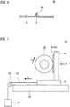
- FIG. 3 is a front view of a test piece 32 prepared in this embodiment.
- the up-down direction is a circumferential direction
- the right-left direction is an axial direction.
- FIG. 4 is a cross-sectional view taken along a line IV-IV in FIG. 3 .
- the direction perpendicular to the surface of the sheet of FIG. 4 is the axial direction.
- the test piece 32 has a cylindrical shape.
- a double-headed arrow W shown in FIG. 3 represents the width, in the axial direction, of the test piece 32.
- the width W, in the axial direction, of the test piece 32 is 18 mm.
- Double-headed arrows di and do shown in FIG. 4 represent the inner diameter and the outer diameter of the test piece 32, respectively.
- the inner diameter di of the test piece 32 is 34 mm, and the outer diameter do of the test piece 32 is 78 mm.
- the wear test is conducted in an inert atmosphere, and the wear amount Ci per unit time (unit: cm 3 /min) is obtained.
- the inert atmosphere means an atmosphere in which chemical action on the vulcanized rubber does not substantially occur or is small.
- a wear test is conducted in a nitrogen atmosphere (room temperature, oxygen concentration: 0.1% by volume or less, relative humidity: 15%).
- the wear test is conducted in an air atmosphere, and the wear amount Ci per unit time (unit: cm 3 /min) is obtained.
- the air atmosphere means an atmosphere of normal air.
- a wear test is conducted in an air atmosphere (room temperature, oxygen concentration: 21% by volume, relative humidity: 50%).
- FIG. 5 is a plan view of a grinding plate 34 used in the wear tests.
- the right-left direction is a longitudinal direction
- the up-down direction is a width direction
- the direction perpendicular to the surface of the sheet of FIG. 5 is a height direction.
- FIG. 6 is a cross-sectional view taken along a line VI-VI in FIG. 5 .
- the right-left direction is the width direction
- the up-down direction is the height direction.
- the grinding plate 34 has a reference surface 38 and one linear projection 36 projecting from the reference surface 38.
- a cross-sectional shape of the linear projection 36 is a mountain shape. Specifically, the cross-sectional shape of the linear projection 36 is an equilateral triangle shape with a side length of 5 mm.
- a double-headed arrow L shown in FIG. 5 represents the length of the linear projection 36.
- a distal end portion (top) of the linear projection 36 is indicated as reference character R.
- the length L of the linear projection 36 is 50 mm, and the radius of curvature of the distal end portion R is 0.01 mm.
- FIG. 7 shows a schematic diagram for describing the wear tests in the first measurement step and the second measurement step.
- the up-down direction is the vertical direction
- the right-left direction is a horizontal direction.
- a testing device 100 is used for the wear tests.
- the testing device 100 includes a fixed base 42 that is installed substantially horizontally, a movable plate 44 that is movably mounted on the fixed base 42, and a pressing plate 46 that is erected on the movable plate 44.
- a pulley 48 is attached to the fixed base 42.
- a connection member 52 is attached to the movable plate 44, and is connected to a load member 50 through a pulley 48.
- the pressing plate 46 has a mounting portion 56.
- the testing device 100 includes a holding means for rotatably holding the test piece 32 at a position facing the mounting portion 56, and a rotating means for rotating the test piece 32.
- FIG. 7 shows a state where the test piece 32 is held with respect to the testing device 100 by the holding means.
- the grinding plate 34 is mounted to the mounting portion 56. At this time, the grinding plate 34 is mounted to the mounting portion 56 such that the surface having the linear projection 36 faces the test piece 32 and the longitudinal direction of the linear projection 36 is substantially parallel to the axial direction of the test piece 32. Thereafter, a predetermined load is applied to the load member 50.
- the load member 50 pulls the movable plate 44, which is connected to the connection member 52 through the pulley 48, in the direction of an arrow G.
- the linear projection 36 on the grinding plate 34 mounted on the pressing plate 46 on the movable plate 44 is pressed against the test piece 32.
- a load is applied to the contact portion between the test piece 32 and the linear projection 36 at a constant pressure in the direction of an arrow F. In the wear test, a load of 0.8 kgf is applied.
- the testing device 100 is operated, and the test piece 32 is rotated by the rotating means in a direction indicated by an arrow S for a predetermined time, thereby moving the test piece 32 and the grinding plate 34 relative to each other.
- the test piece 32 is rotated at a rotation speed of 60 rpm and a slip angle of 0°.
- the outer peripheral surface of the test piece 32 is worn.
- a part of the vulcanized rubber forming the outer peripheral surface of the test piece 32 peels off from the test piece 32.
- each of the first measurement step and the second measurement step after a predetermined time elapses from the time when the testing device 100 is operated, the test piece 32 is removed, and a mass change W before and after the wear test is measured.
- a wear volume (unit: cm 3 ) is obtained by dividing this mass change by a specific gravity d of the vulcanized rubber forming the test piece 32.
- a wear amount per unit time (unit: cm 3 /min) is obtained by dividing this wear volume by a time for which the test piece 32 and the grinding plate 34 are moved relative to each other, that is, a rotation time (min) of the test piece 32.
- the method for measuring the specific gravity of the vulcanized rubber will be described later in EXAMPLES.
- a change rate R (%) is calculated by the following equation, using a wear amount Ci per unit time in the inert atmosphere obtained in the first measurement step and a wear amount Ca per unit time in the air atmosphere obtained in the second measurement step.
- Change rate R % Ca ⁇ Ci / Ca ⁇ 100
- the wear performance of the vulcanized rubber forming the test piece 32 is evaluated using the calculated change rate R (%) as an index.
- an evaluation result obtained by using the change rate R as an index reflect the market's evaluation of the wear resistance of the tire 2.
- the change rate R as an index, the wear performance of a vulcanized rubber forming a tire member can be accurately and easily evaluated. Specifically, by applying the makeup of a vulcanized rubber having a change rate R not greater than 60% to a member included in the tire 2, the tire 2 having excellent wear resistance is obtained.
- the types and number of members formed from the vulcanized rubber having a change rate R not greater than 60% are not particularly limited. From the viewpoint of reducing wear due to contact with a road surface during running, the tread 4 and the sidewall 6 are preferable, and the tread 4 is particularly preferable, as a member formed form the vulcanized rubber.
- the method for obtaining a member formed from the vulcanized rubber having a change rate R not greater than 60% is not particularly limited.
- an apparatus and a facility for producing the tire 2 including the member formed from the vulcanized rubber are not particularly limited, and a known apparatus and facility can be used.
- the tire 2 including the tread 4 that is formed from the vulcanized rubber is produced by the following procedure.
- an unvulcanized rubber composition containing a base rubber and various additives that are normally used in the tire field is prepared so as to have a makeup for which a change rate R is not greater than 60%.
- the rubber composition is extruded into the shape of the tread 4, and then attached together with other tire members on a known tire-shaping machine, thereby obtaining a raw cover (unvulcanized tire).
- the raw cover is put into a mold.
- the outer surface of the raw cover comes into contact with the cavity face of the mold.
- the inner surface of the raw cover comes into contact with a bladder or a core.
- the raw cover is pressurized and heated in the mold. Due to the pressurization and the heating, the rubber composition of the raw cover flows. Due to the heating, a crosslinking reaction of the rubber takes place to obtain the tire 2.
- An uneven pattern is formed on the tire 2 by using a mold having an uneven pattern on its cavity surface.
- the types of the base rubber and the various additives to be blended in the rubber composition are not particularly limited as long as the change rate R obtained by the above-described evaluation method is not greater than 60%.
- Examples of preferable base rubbers include natural rubber, styrene-butadiene rubber, butadiene rubber, epoxidized natural rubber, isoprene rubber, ethylene-propylene-diene rubber, chloroprene rubber, acrylonitrile-butadiene rubber, acrylonitrile-butadiene-styrene rubber. Two or more rubbers may be used in combination as the base rubber.
- a particularly preferable base rubber is a styrene-butadiene rubber in which the degree of hydrogenation of conjugated diene moieties is not less than 50% by mole and not greater than 99% by mole.
- the degree of hydrogenation of conjugated diene moieties of the styrene-butadiene rubber is more preferably not less than 55% by mole and particularly preferably not less than 60% by mole.
- the degree of hydrogenation of conjugated diene moieties exceeds 99% by mole so that unsaturated bonds in the rubber molecular chain are extremely reduced as in non-diene rubbers such as isobutylene-isoprene-rubber, the vulcanization reaction rate is decreased, and tire performance such as low fuel consumption performance and wet grip performance may deteriorate due to low affinity with a reinforcing agent such as silica.
- the degree of hydrogenation of conjugated diene moieties of the styrene-butadiene rubber is more preferably not greater than 98% by mole.
- the proportion of the styrene-butadiene rubber in which the degree of hydrogenation of conjugated diene moieties is not less than 50% by mole and not greater than 99% by mole, in the base rubber is preferably not less than 40% by mass, more preferably not less than 60% by mass, further preferably not less than 80% by mass, and particularly preferably not less than 90% by mass, and the upper limit thereof is 100% by mass.
- a rubber composition containing no isobutylene-isoprene-rubber is preferable.
- additives to be blended together with the base rubber include fillers such as carbon black and silica, silane coupling agents, oils, waxes, zinc oxide, antioxidants, processing aids, resins, crosslinking agents, vulcanizing agents, vulcanization accelerators, and vulcanization accelerator aids. As long as the advantageous effects of the present invention are not impaired, other additives that are not described in the present description may also be used.
- the makeup of the rubber composition is not particularly limited.
- the makeup of the composition is adjusted as appropriate according to the makeup of a conventionally known tire rubber composition such that the change rate R obtained by the above-described evaluation method is not greater than 60%.
- a typical example is a makeup for tread rubber.
- the shape of the test piece 32 prepared in the preparation step is not particularly limited. From the viewpoint of easily reproducing the state during running of an actual vehicle in the wear test, the cylindrical shape shown in FIGS. 3 and 4 is preferable.
- the number of test pieces 32 to be prepared in the preparation step is at least two, one of the test pieces is subjected to the first measurement step, and the other test piece is subjected to the second measurement step. From the viewpoint of evaluation accuracy, two or more test pieces 32 are preferably subjected to each measurement step.
- the method for preparing the test piece 32 is also not particularly limited.
- the test piece 32 may be prepared by: putting the above-described base rubber and various additive into an open roll, a Banbury mixer, or the like and kneading these materials therein to prepare a rubber composition; and heating and pressurizing the rubber composition in a mold having a predetermined shape.
- the test piece 32 may be prepared by press-vulcanizing the prepared rubber composition to produce a rubber sheet, cutting the rubber sheet as appropriate, and attaching the cut rubber sheet to the outer peripheral surface of a rotating body having the basic structure shown in FIGS. 3 and 4 .
- the test piece 32 may be prepared by: extruding the prepared rubber composition into the shape of the tread 4, attaching the extruded rubber composition together with other tire members, and heating and pressurizing these members in a vulcanizing machine, thereby producing the tire 2; and attaching a sheet-shaped rubber piece cut out from the surface of the tread 4 of the tire 2, to the outer peripheral surface of the above rotating body.
- the material of the rotating body to which the rubber sheet or the sheet-shaped rubber piece is attached is not particularly limited, but, from the viewpoint of improving the evaluation accuracy, a vulcanized rubber having a hardness substantially equal to that of the rubber sheet or the rubber piece is preferable.
- the size of the test piece 32 is not particularly limited.
- the width W, in the axial direction, of the test piece 32 is preferably not less than 15 mm and more preferably not less than 18 mm.
- the width W in the axial direction is preferably not greater than 22 mm and more preferably not greater than 20 mm.
- the outer diameter do of the cylindrical test piece 32 is preferably not less than 50 mm and more preferably not less than 60 mm. From the viewpoint of making the device compact, the outer diameter do is preferably not greater than 120 mm and more preferably not greater than 100 mm.
- the inner diameter di of the test piece 32 is adjusted as appropriate in accordance with the outer diameter do. From the viewpoint of reproducing the running state on an actual road surface, the inner diameter di of the test piece 32 is preferably not less than 10 mm and more preferably not less than 15 mm. From the viewpoint of inhibiting deformation of the test piece 32 during the wear test, the inner diameter di is preferably not greater than 45 mm.
- the thickness of the rubber sheet or the rubber piece is preferably not less than 0.5 mm and more preferably not less than 1 mm.
- the thickness of the rubber sheet or the rubber piece is preferably not greater than 4 mm.
- the inert atmosphere in the first measurement step is not particularly limited as long as chemical action on the vulcanized rubber forming the test piece 32 is inhibited.
- the inert atmosphere may be, for example, an inert gas atmosphere such as nitrogen, carbon dioxide, argon, and helium, may be in a vacuum state, or may be in a reduced pressure state. Two or more inert gases may be used in combination. A nitrogen atmosphere or an argon atmosphere is preferable.
- the oxygen concentration of the inert atmosphere is preferably not greater than 15% by volume, more preferably not greater than 12% by volume, further preferably not greater than 10% by volume, and particularly preferably not greater than 8% by volume.
- the lower limit of the oxygen concentration of the inert atmosphere is not particularly limited, and sufficient evaluation accuracy is achieved at an oxygen concentration of 5% by volume. From the viewpoint of simplifying the wear test, the lower limit of the oxygen concentration of the inert atmosphere is 0.001% by volume.
- the air atmosphere in the second measurement step means an atmosphere having an oxygen concentration of 20 to 22% by volume, and normally means an atmosphere of air having an oxygen concentration of 21% by volume and a nitrogen concentration of 78% by volume.
- the inert atmosphere and the air atmosphere may be included in the inert atmosphere and the air atmosphere.
- the relative humidity thereof is preferably not less than 40% and not greater than 60% in the air atmosphere, and preferably not less than 10% and not greater than 20% in the inert atmosphere.
- the test temperature of the wear test in each of the first measurement step and the second measurement step is determined as appropriate according to the environment in which the vulcanized rubber to be evaluated for wear performance is used. Unless otherwise limited, the test temperature of the wear test is preferably not lower than 15°C and not higher than 35°C, and more preferably not lower than 22°C and not higher than 26°C.
- the "room temperature” in the present description normally means not lower than 22°C and not higher than 26°C.
- a wear tester is used for each wear test.
- the wear tester is installed in an inert atmosphere.
- the wear tester is installed in an air atmosphere.
- the test temperature of each wear test is normally the outside air temperature at the place where the wear tester is installed.
- the type of the wear tester is not particularly limited.
- a known wear tester such as a DIN wear tester, a Lambourn wear tester, and a LAT100 wear tester may be used, or the testing device 100 shown in FIG. 7 may be used.
- the wear tester normally has a pseudo road surface for wearing a test piece.
- the type of the pseudo road surface of the wear tester is not particularly limited.
- the pseudo road surface may be, for example, a pseudo road surface obtained by attaching grindstone, sandpaper, safety walk, or the like, or may be an asphalt road surface, a concrete road surface, or the like.
- the grain size of the grindstone is preferably #60 to #240.
- test piece and the pseudo road surface are moved relative to each other for a predetermined time.
- the method for moving the test piece and the pseudo road surface relative to each other is not particularly limited.
- the test piece may be fixed and the pseudo road surface may be moved, the pseudo road surface may be fixed and the test piece may be moved, or both the test piece and the pseudo road surface may be mutually moved.
- the load to the test piece is not particularly limited. From the viewpoint of reproducing the running condition on an actual road surface, a load of preferably 0.5 kgf or greater and more preferably 0.6 kgf or greater is applied to the test piece 32. From the viewpoint of preventing deformation and breakage of the test piece 32, a load of preferably 4.0 kgf or less and more preferably 3.5 kgf or less is applied to the test piece 32.
- the rotation speed of the test piece 32 is preferably not less than 10 rpm and more preferably not less than 30 rpm. From the viewpoint of inhibiting heat generation and deformation of the test piece 32, the rotation speed is preferably not greater than 180 rpm and more preferably not greater than 120 rpm.
- the rotation time of the test piece 32 is selected as appropriate such that the wear amounts Ci and Ca that can be evaluated are obtained. From the viewpoint of measurement accuracy, the rotation time is preferably not shorter than 5 minutes. From the viewpoint of inhibiting heat generation and deformation of the test piece 32, the rotation time is not longer than 120 minutes.
- the wear test may be conducted in a state where a slip angle is applied to the test piece 32.
- the slip angle is an angle formed between the rotation surface (equator plane) of the cylindrical test piece 32 and the direction of movement relative to the pseudo road surface.
- the slip angle is not particularly limited. From the viewpoint of evaluation accuracy and wear efficiency, the slip angle is preferably 0° to 15°.
- the grinding plate 34 having one or a large number of linear projections 36 is preferable.
- the number and the arrangement of the linear projections 36 of the grinding plate 34 are not particularly limited, and are selected as appropriate in accordance with the shape of the test piece 32.
- the material of the grinding plate 34 and the material of each linear projection 36 may be the same or different from each other. From the viewpoint of test efficiency and durability, aluminum, stainless steel, iron, etc., are suitably used as the materials.
- the length L of the linear projection 36 is not particularly limited, and is selected as appropriate in accordance with the shape and the size of the test piece 32.
- the length L of the linear projection 36 is preferably larger than the width W, in the axial direction, of the test piece 32.
- the length L of the linear projection 36 is preferably not less than 20 mm and more preferably not less than 30 mm.
- the upper limit of the length L is not particularly limited, but, from the viewpoint of making the device compact, the length L is preferably not greater than 200 mm.
- the cross-sectional shape of the linear projection 36 is not particularly limited, and a mountain shape, a rectangular shape, a polygonal shape, or the like is selected as appropriate.
- the grinding plate 34 may have a plurality of linear projections 36 having different cross-sectional shapes.
- the radius of curvature of the distal end portion R of the linear projection 36 is preferably not greater than 1.00 mm, more preferably not greater than 0.80 mm, and particularly preferably not greater than 0.60 mm. From the viewpoint of durability, the lower limit of the radius of curvature is 0.01 mm.
- the radius of curvature of the linear projection 36 is measured in the cross-section of FIG. 6 .
- the height of the linear projection 36 is preferably not less than 1.0 mm and more preferably not less than 1.5 mm. From the viewpoint of preventing breakage of the test piece 32, the height is preferably not greater than 10 mm. In the case where the grinding plate 34 has a plurality of linear projections 36, the pitch between each linear projection 36 is preferably not less than 0.5 mm and not greater than 6.0 mm.
- the evaluation result of the wear performance of the vulcanized rubber obtained by the evaluation method according to the present invention correlates with the market's evaluation result of the wear resistance of the tire 2 including the member formed from the vulcanized rubber.
- the dimensions and angles of the members of the tire 2 are measured in a state where the tire 2 is mounted on a normal rim and inflated with air to a normal internal pressure and a normal load is applied to the tire 2.
- the normal rim means a rim specified in a standard on which the tire 2 is based.
- the "standard rim” in the JATMA standard, the "Design Rim” in the TRA standard, and the "Measuring Rim” in the ETRTO standard are normal rims.
- the normal internal pressure means an internal pressure specified in the standard on which the tire 2 is based.
- the "highest air pressure” in the JATMA standard, the “maximum value” recited in “TIRE LOAD LIMITS AT VARIOUS COLD INFLATION PRESSURES" in the TRA standard, and the “INFLATION PRESSURE” in the ETRTO standard are normal internal pressures.
- the normal load means a load specified in the standard on which the tire 2 is based.
- test temperature is room temperature.
- Test 1 a plurality of test pieces were prepared by using rubber compositions having different makeups, the wear test shown in FIG. 7 was conducted, and a change rate R (%) was calculated from the obtained wear amounts per unit time in the inert atmosphere and in the air atmosphere.
- n-hexane manufactured by KANTO CHEMICAL CO., INC.
- 60 g of styrene manufactured by KANTO CHEMICAL CO., INC.
- 140 g of 1,3-butadiene manufactured by Tokyo Chemical Industry Co., Ltd.
- 2.5 g of tetrahydrofuran manufactured by KANTO CHEMICAL CO., INC.
- 0.45 mmol of n-butyllithium 1.6 M n-butyllithium/hexane solution, manufactured by KANTO CHEMICAL CO., INC.
- the degree of hydrogenation of conjugated diene moieties of the SBR 1 was calculated from the rate of decrease in the signal cumulative value of the obtained NMR spectrum corresponding to unsaturated bonds.
- a stainless steel polymerization reactor having an inner volume of 20 L was washed, dried, and purged with dry nitrogen. Then, 10.2 kg of the above-described n-hexane (specific gravity: 0.68 g/cm 3 ), 547 g of the above-described 1,3-butadiene, 173 g of the above-described styrene, 6.1 ml of the above-described tetrahydrofuran, and 5.0 ml of ethylene glycol diethyl ether were put into the polymerization reactor. Subsequently, 13.1 mmol of the above-described n-butyllithium was added to initiate polymerization.
- the polymerization was continued at a stirring speed of 130 rpm and a temperature of 65°C in the polymerization reactor for 3 hours.
- the amount of the 1,3-butadiene supplied in this polymerization was 821 g, and the amount of the styrene supplied in this polymerization was 259 g.
- 11.1 mmol of 3-diethylaminopropyltriethoxysilane was added to the obtained polymer solution while stirring the polymer solution at a stirring speed of 130 rpm, and then the polymer solution was stirred for 15 minutes.
- the obtained rubber composition was put into a mold and press-vulcanized at 170°C for 12 minutes, thereby preparing test pieces A1 and A2 having the cylindrical shape (outer diameter: 78 mm, inner diameter: 34 mm, width in the axial direction thereof: 18 mm) shown in FIGS. 3 and 4 .
- Test pieces B1 to H1 and B2 to H2 were prepared in the same manner as the test pieces A1 and A2, except that the makeup of the rubber composition was changed to those shown as B to D in Table 1 below and E to H in Table 2 below.
- Table 1 (Table 1) (parts by mass) A B C D Base rubber SBR 1 100 100 100 0 SBR 2 0 0 0 100 Carbon black 5 5 5 5 5 Silica 60 60 60 60 Coupling agent 5.2 5.2 5.2 5.2 Oil 32 32 32 28 Antioxidant TMQ 1 5 0 1 AO 0 0 5 0 Stearic acid 2 2 2 2 2 Zinc oxide 2 2 2 2 Sulfur 1.6 0.8 0.8 1.6 Crosslinking agent 0 1 1 0 Vulcanization accelerator BBS 1.8 1.8 1.8 1.8 DPG 2.2 2.2 2.2 2.2 Specific gravity 1.155 1.133 1.133 1.142 R (%) 44 35 24 62 [Table 2] (Table 2) (parts by mass) E F G H Base rubber SBR 1 0 50 0 0
- Base rubber SBR 1 the styrene-butadiene rubber of Production Example 1 (degree of hydrogenation: 96% by mole, styrene content: 30% by mass, weight-average molecular weight: 450 thousand, glass transition temperature: -31°C)
- Base rubber SBR 2 the styrene-butadiene rubber of Production Example 2 (styrene content: 25% by mass, vinyl content: 59% by mass)
- Carbon black trade name "SEAST 9H" (DBP absorption amount: 115 ml/g, BET specific surface area: 110 m 2 /g) manufactured by Tokai Carbon Co., Ltd.
- Silica trade name "ULTRASIL VN3" (N 2 SA: 175 m 2 /g) manufactured by Evonik Degussa GmbH Coupling agent: 8-mercaptooctanoyltriethoxysilane, trade name "NXT”, manufactured by Momentive Oil: TDAE oil, trade name "Vivatec 500", manufactured by H&R Antioxidant TMQ: 2,2,4-trimethyl-1,2-dihydroquinoline polymer, trade name "NOCRAC 224", manufactured by Ouchi Shinko Chemical Industrial Co., Ltd.
- Antioxidant AO 3,9-bis ⁇ 2-[3-(3-tert-butyl-4-hydroxy-5-methylphenyl)propionyloxy]-1,1-dimethylethyl ⁇ -2,4,8,10-tetraoxaspiro[5.5]undecane, trade name "ADEKA STAB AO-80", manufactured by ADEKA Corporation Stearic acid: trade name "Tsubaki”, manufactured by NOF Corporation Zinc oxide: trade name "Zinc Oxide Type-2", manufactured by Mitsui Mining & Smelting Co., Ltd. Sulfur: powdery sulfur manufactured by Tsurumi Chemical Industry Co., Ltd.
- Crosslinking agent 1,6-bis(N,N'-dibenzylthiocarbamoyldithio)hexane, trade name "Vulcuren VP KA9188" (amount of sulfur: 20.6% by mass), manufactured by LANXESS
- Vulcanization accelerator BBS N-tert-butyl-2-benzothiazolyl sulfenamide, trade name "NOCCELER NS”, manufactured by Ouchi Shinko Chemical Industrial Co., Ltd.
- Vulcanization accelerator DPG 1,3-diphenylguanidine, trade name "SOXINOL D", manufactured by Sumitomo Chemical Company, Limited
- the test piece A1 was set on a testing device having the basic structure shown in FIG. 7 .
- a grinding plate having the structure shown in FIGS. 5 and 6 was mounted on the pressing plate of the testing device.
- the grinding plate has one linear projection (length: 50 mm), and a cross-sectional shape thereof was a mountain shape (an equilateral triangle shape with a side length of 5 mm, the radius of curvature of a distal end portion was 0.01 mm).
- the testing device was operated in a nitrogen atmosphere (room temperature, oxygen concentration: 0.1% by volume or less, relative humidity: 15%), and a wear test was conducted on the test piece A1 under the following conditions. Load: 0.8 kgf Rotation speed: 60 rpm Slip angle: 0° Rotation time: 20 minutes
- test piece A2 was set on the testing device in place of the test piece A1. Thereafter, a wear test was conducted on the test piece A2 in the same manner as the test piece A1, except that the nitrogen atmosphere was changed to an air atmosphere (room temperature, oxygen concentration: 21% by volume, relative humidity: 50%).
- Each of the obtained test tires A to H was fitted onto a normal rim and inflated with air to an internal pressure of 180 kPa. Then, a running test was conducted to evaluate wear resistance. Specifically, a driver drove a test vehicle (an FF car produced in Japan with an engine displacement of 2000 cc) having the tires mounted thereon, on a test course having an asphalt road surface at a speed of 80 km/hour for 30,000 km. Thereafter, the groove depth (unit: mm) of the tread was measured, and the running distance per 1 mm of depth decreased due to the running (unit: km/mm) was calculated. An index obtained with the value for the test tire D being regarded as 100 is shown as wear resistance 1 in Tables 3 and 4 below. The higher the value is, the higher the evaluation is.
- the test tires A to C and E to G each include a tread formed from a vulcanized rubber having a change rate R not greater than 60%.
- the test tires D and H each include a tread formed from a vulcanized rubber of Makeups D and H each having a change rate R greater than 60%. From Tables 3 and 4, it is found that the wear resistance of the obtained tire was improved by using the vulcanized rubber having a makeup having a small change rate R (%) not greater than 60% and having small contribution to chemical wear.
- test pieces formed from vulcanized rubbers of Makeups A and D were prepared.
- a wear test was conducted on each test piece in an air atmosphere (room temperature, oxygen concentration: 21% by volume, relative humidity: 50%) using the testing device described above in Test 1, and a wear amount per unit time was obtained.
- the test conditions are as follows. Load: 0.8 kgf Rotation speed: 60 rpm Slip angle: 0° Rotation time: 20 minutes
- An index obtained with the wear amount for Makeup D being regarded as 100 is shown as a wear index in Table 5 below. The lower the value is, the higher the evaluation is.
- the evaluation results by the vehicle running test described above are also shown as wear resistance 2 for comparison.
- the wear resistance 2 is an index obtained with the value for the test tire D being regarded as 100. From Table 5, it is found that the wear index by Test 3 does not reflect the wear resistance 2 by the vehicle test.
- the pneumatic tire described above can be mounted to various vehicles.
- the evaluation method described above can be applied to production of tires having various shapes and including members formed from vulcanized rubbers.
- the wear amounts Ci and Ca are each obtained by: rotating a cylindrical test piece formed from the vulcanized rubber, in a circumferential direction thereof in a state where a grinding plate having a linear projection is pressed against an outer peripheral surface of the test piece and a load is applied to the test piece, thereby conducting a wear test; and dividing a wear volume calculated from a specific gravity of the vulcanized rubber and a mass change of the test piece measured before and after the wear test, by a total rotation time.
Landscapes
- Chemical & Material Sciences (AREA)
- Health & Medical Sciences (AREA)
- Chemical Kinetics & Catalysis (AREA)
- Medicinal Chemistry (AREA)
- Polymers & Plastics (AREA)
- Organic Chemistry (AREA)
- General Chemical & Material Sciences (AREA)
- Engineering & Computer Science (AREA)
- Mechanical Engineering (AREA)
- Tires In General (AREA)
Abstract
Description
- The present invention relates to a pneumatic tire. Specifically, the present invention relates to a pneumatic tire and a wear performance evaluation method for a vulcanized rubber for forming the tire.
- A tire includes various members each formed by using a vulcanized rubber. One of these members is a tread. During running of a vehicle, each tire comes into contact with a road surface at the tread thereof. Due to the contact with the road surface, the tire wears gradually. Due to the wear of the tire, the tire performance deteriorates. In recent years, further improvement of the wear resistance of pneumatic tires is required.
- A technology for evaluating the wear performance of a vulcanized rubber is important in developing a tire having excellent wear resistance. For example, in a conventional evaluation method by a running test, first, a tire member is formed using a vulcanized rubber to be evaluated. Next, a tire formed so as to include the tire member is mounted to a test vehicle, and the test vehicle is caused to run, thereby evaluating the wear performance of the vulcanized rubber. In addition, a method for evaluating the wear performance of the vulcanized rubber by rotating the tire on a drum of a drum type tester has also been proposed.
- In the running tests using the actual vehicle and the drum type tester, for each of various vulcanized rubbers having different makeups, it is necessary to produce tires. In addition, to accurately evaluate the wear performance of each vulcanized rubber, a long running time is required.
- Various wear testers for evaluating the wear performance of a vulcanized rubber by using a test piece formed from the vulcanized rubber without actually producing a tire, have also been proposed. However, evaluation results obtained by these wear testers do not necessarily correlate with evaluation results by a running test and wear resistance evaluation in the market.
- As for wear of vulcanized rubbers, physical wear due to crack growth and chemical wear accompanied by mechanochemical reactions are known. According to the findings of the present inventors, it has been speculated that the contribution of chemical wear to the market's evaluation of the wear resistance of tires is not small, but a technology for evaluating chemical wear separately from physical wear has not existed hitherto. Therefore, a pneumatic tire that can satisfy high wear resistance demanded in the market has not been realized yet. An object of the present invention is to provide a pneumatic tire having excellent wear resistance.
- In addition, from the viewpoint of speeding up tire development, there is also a demand for a method for easily and accurately evaluating the wear performance of a vulcanized rubber that reflects the market's evaluation of wear resistance. Another object of the present invention is to provide a method for accurately evaluating the wear performance of a vulcanized rubber used for the pneumatic tire.
- As a result of a thorough study, the present inventors have focused on the fact that the chemical wear of a vulcanized rubber has a great influence on the wear resistance of a tire including a member formed from the vulcanized rubber. Then, the present inventors have completed the present invention by finding a method, for evaluating chemical wear separately from physical wear, which has not existed hitherto.
- Specifically, a pneumatic tire according to the present invention includes a member formed from a vulcanized rubber having a makeup for which a change rate R (%) defined by the following equation using a wear amount Ci per unit time (unit: cm3/min) obtained in a wear test in a nitrogen atmosphere (room temperature, oxygen concentration: 0.1% by volume or less, relative humidity: 15%) and a wear amount Ca per unit time (unit: cm3/min) obtained in a wear test in an air atmosphere (room temperature, oxygen concentration: 21% by volume, relative humidity: 50%) is not greater than 60%.

- Preferably, the member formed from the vulcanized rubber is formed by heating and pressurizing a rubber composition. The rubber composition contains, as a base rubber, a styrene-butadiene rubber in which a degree of hydrogenation of conjugated diene moieties is not less than 50% by mole and not greater than 99% by mole. Preferably, a proportion of the styrene-butadiene rubber in the base rubber is not less than 40% by mass and not greater than 100% by mass.
- Preferably, the member formed from the vulcanized rubber is a tread.
- According to another aspect, a wear performance evaluation method for a vulcanized rubber according to the present invention includes:
- (1) a preparation step of preparing at least two test pieces formed from a vulcanized rubber having the same makeup;
- (2) a first measurement step of conducting a wear test in an inert atmosphere and obtaining a wear amount Ci per unit time;
- (3) a second measurement step of conducting a wear test in an air atmosphere and obtaining a wear amount Ca per unit time; and
- (4) an evaluation step of evaluating wear resistance of the vulcanized rubber on the basis of a change rate R (%) calculated by the equation: R = (Ca-Ci)/Ca × 100 using the wear amounts Ci and Ca.
- Preferably, an oxygen concentration of the inert atmosphere is not greater than 15% by volume. Preferably, the inert atmosphere is a nitrogen atmosphere or an argon atmosphere.
- Preferably, in each of the first measurement step and the second measurement step, the wear test is conducted using a testing device having a pseudo road surface. The wear test is conducted by moving the pseudo road surface and the test piece relative to each other for a predetermined time in a state where the pseudo road surface is pressed against the test piece and a load is applied to the test piece. A wear volume is obtained by dividing a mass change of the test piece measured before and after the wear test by a specific gravity of the vulcanized rubber. The wear amount Ci and the wear amount Ca per unit time were each obtained by dividing the wear volume by the time of the relative movement.
- Preferably, each of the test pieces has a cylindrical shape. Preferably, the pseudo road surface has one or a large number of linear projections. Preferably, the test piece is rotated in the circumferential direction thereof in a state where said one or said large number of linear projections are pressed against an outer peripheral surface of the test piece and a load is applied to the test piece, thereby conducting the wear test.
- The member included in the pneumatic tire according to the present invention is formed from the vulcanized rubber having a change rate R not greater than 60%. The member formed from the vulcanized rubber is less susceptible to chemical wear. In the tire including the member formed from the vulcanized rubber, high wear resistance is achieved. With the evaluation method according to the present invention, the wear performance of the vulcanized rubber can be evaluated separately for physical wear and for chemical wear. Accordingly, an evaluation result reflecting wear resistance by running of an actual vehicle is obtained.
-
-
FIG. 1 is a cross-sectional view of a pneumatic tire according to an embodiment of the present invention; -
FIG. 2 is a flowchart showing an evaluation method according to an embodiment of the present invention; -
FIG. 3 is a front view of a test piece prepared in a preparation step inFIG. 2 ; -
FIG. 4 is a cross-sectional view of the test piece inFIG. 3 taken along a line IV-IV; -
FIG. 5 is a plan view of a part of a grinding plate used in each measurement step inFIG. 2 ; -
FIG. 6 is a partial cross-sectional view of the grinding plate inFIG. 5 taken along a line VI-VI; and -
FIG. 7 is a schematic diagram for describing a wear test in each measurement step inFIG. 2 . - Hereinafter, the present invention will be described in detail based on preferred embodiments with appropriate reference to the drawings. However, the present invention is not limited to the following embodiments, and various modifications may be made without departing from the scope indicated by the claims. In the present description, unless otherwise specified, "X to Y" means "not less than X and not greater than Y", and "%" means "% by mass".
-
FIG. 1 is a cross-sectional view of atire 2 according to an embodiment of the present invention. InFIG. 1 , the up-down direction is the radial direction of thetire 2, the right-left direction is the axial direction of thetire 2, and the direction perpendicular to the surface of the sheet ofFIG. 1 is the circumferential direction of thetire 2. InFIG. 1 , an alternate long and short dash line CL represents the equator plane of thetire 2. For each constituent member, only the contour of a cross-section thereof is shown inFIG. 1 . - The
tire 2 includes atread 4, a pair ofsidewalls 6, a pair ofbeads 8, acarcass 10, abelt 12, aband 14, and aninner liner 16. Thetire 2 is a pneumatic tire to be mounted to a passenger car. - The
tread 4 has a shape that is convex outward in the radial direction. Thetread 4 has atread surface 20.Grooves 22 are formed on thetread surface 20. Thetread 4 is formed from a vulcanized rubber. - Each
sidewall 6 extends substantially inward in the radial direction from an end of thetread 4. Eachbead 8 is located radially inward of thesidewall 6. Thebead 8 includes acore 24 and an apex 26 extending radially outward from thecore 24. Thecarcass 10 includes acarcass ply 28. The carcass ply 28 extends between and on bothbeads 8 along thetread 4 and thesidewalls 6. The carcass ply 28 is turned up around each core 24 from the inner side toward the outer side in the axial direction. - The
belt 12 is located radially inward of thetread 4 and laminated on thecarcass 10. Thebelt 12 includes aninner layer 12a and anouter layer 12b. Theband 14 is laminated radially outward of thebelt 12. Theband 14 includes a cord and a topping rubber, which are not shown. The cord extends substantially in the circumferential direction and is spirally wound. Theband 14 has a so-called jointless structure. Theinner liner 16 is located radially inward of thecarcass 10 and joined to the inner surface of thecarcass 10. - In the
tire 2 according to the embodiment, the vulcanized rubber forming thetread 4 has a change rate R (%) not greater than 60%, and the change rate R is defined by the equation: R (%) = (Ca-Ci)/Ca × 100, using a wear amount Ci per unit time (unit: cm3/min) obtained in a wear test in a nitrogen atmosphere (room temperature, oxygen concentration: 0.1% by volume or less, relative humidity: 15%) and a wear amount Ca per unit time (unit: cm3/min) obtained in a wear test in an air atmosphere (room temperature, oxygen concentration: 21% by volume, relative humidity: 50%). The wear amount Ci and the wear amount Ca are each obtained by: preparing a cylindrical test piece (outer diameter: 78 mm, inner diameter: 34 mm, width in the axial direction thereof: 18 mm) formed from the vulcanized rubber, and a testing device including a grinding plate having one linear projection (an equilateral triangle shape with a side length of 5 mm in a cross-sectional view, the radius of curvature of a distal end portion is 0.01 mm); rotating the test piece in the circumferential direction thereof at a rotation speed of 60 rpm and a slip angle of 0°, in a state where the surface of the grinding plate on which the linear projection is formed is pressed against the outer peripheral surface of the test piece and a load of 0.8 kgf is applied to the test piece, thereby conducting a wear test; and dividing a wear volume (unit: cm3), which is obtained by dividing a mass change of the test piece measured before and after the wear test by the specific gravity of the vulcanized rubber, by the total rotation time (unit: min) of the test piece. - In the wear test in the nitrogen atmosphere, physical wear mainly occurs. In the above equation, Ci is mainly a wear amount per unit time based on physical wear. Meanwhile, in the wear test in the air atmosphere, chemical wear and physical wear occur. In the above equation, Ca is a total wear amount per unit time based on chemical wear and physical wear. Therefore, the change rate R defined by the above equation is a value indicating the proportion of chemical wear in total wear the vulcanized rubber is subjected to. A vulcanized rubber having a makeup having a change rate R not greater than 60% has resistance to chemical wear. The
tire 2 including thetread 4 that is formed from the vulcanized rubber has excellent wear resistance. Another member forming a part of thetire 2 may be formed from the vulcanized rubber. - Here, a change rate R is an index indicating resistance to chemical wear of a vulcanized rubber. The change rate R can reflect the market's evaluation of the wear resistance of a tire including a member formed from the vulcanized rubber. By using the change rate R as an index, the wear performance of the vulcanized rubber forming a constituent member of a tire can be accurately and easily evaluated. In other words, the method for obtaining the change rate R is a method for evaluating the wear performance of the vulcanized rubber. Hereinafter, an evaluation method according to an embodiment of the present invention will be specifically described with reference to
FIGS. 2 to 7 . -
FIG. 2 shows a flowchart for obtaining the change rate R by using the evaluation method according to the embodiment of the present invention. As shown, the evaluation method includes at least a preparation step, a first measurement step in an inert atmosphere, a second measurement step in an air atmosphere, and an evaluation step. As long as the advantageous effects of the present invention are obtained, the evaluation method can further include another step. - In the preparation step, at least two test pieces formed from a vulcanized rubber having the same makeup are prepared. In this embodiment, a first test piece to be subjected to the first measurement step and a second test piece to be subjected to the second measurement step are prepared. Preferably, the first test piece and the second test piece have the same shape. Hereinafter, the first test piece and the second test piece are sometimes collectively referred to as "test piece".
-
FIG. 3 is a front view of atest piece 32 prepared in this embodiment. InFIG. 3 , the up-down direction is a circumferential direction, and the right-left direction is an axial direction.FIG. 4 is a cross-sectional view taken along a line IV-IV inFIG. 3 . InFIG. 4 , the direction perpendicular to the surface of the sheet ofFIG. 4 is the axial direction. - As shown in
FIGS. 3 and4 , thetest piece 32 has a cylindrical shape. A double-headed arrow W shown inFIG. 3 represents the width, in the axial direction, of thetest piece 32. The width W, in the axial direction, of thetest piece 32 is 18 mm. Double-headed arrows di and do shown inFIG. 4 represent the inner diameter and the outer diameter of thetest piece 32, respectively. The inner diameter di of thetest piece 32 is 34 mm, and the outer diameter do of thetest piece 32 is 78 mm. - In the first measurement step, a wear test is conducted in an inert atmosphere, and the wear amount Ci per unit time (unit: cm3/min) is obtained. In the present description, the inert atmosphere means an atmosphere in which chemical action on the vulcanized rubber does not substantially occur or is small. In the first measurement step of this embodiment, a wear test is conducted in a nitrogen atmosphere (room temperature, oxygen concentration: 0.1% by volume or less, relative humidity: 15%).
- In the second measurement step, a wear test is conducted in an air atmosphere, and the wear amount Ci per unit time (unit: cm3/min) is obtained. In the present description, the air atmosphere means an atmosphere of normal air. In the second measurement step of this embodiment, a wear test is conducted in an air atmosphere (room temperature, oxygen concentration: 21% by volume, relative humidity: 50%).
- In this embodiment, a grinding plate having a linear projection is used in the wear tests in the first measurement step and the second measurement step.
FIG. 5 is a plan view of a grindingplate 34 used in the wear tests. InFIG. 5 , the right-left direction is a longitudinal direction, the up-down direction is a width direction, and the direction perpendicular to the surface of the sheet ofFIG. 5 is a height direction.FIG. 6 is a cross-sectional view taken along a line VI-VI inFIG. 5 . InFIG. 6 , the right-left direction is the width direction, and the up-down direction is the height direction. - As shown, the grinding
plate 34 has areference surface 38 and onelinear projection 36 projecting from thereference surface 38. A cross-sectional shape of thelinear projection 36 is a mountain shape. Specifically, the cross-sectional shape of thelinear projection 36 is an equilateral triangle shape with a side length of 5 mm. A double-headed arrow L shown inFIG. 5 represents the length of thelinear projection 36. InFIG. 6 , a distal end portion (top) of thelinear projection 36 is indicated as reference character R. The length L of thelinear projection 36 is 50 mm, and the radius of curvature of the distal end portion R is 0.01 mm. -
FIG. 7 shows a schematic diagram for describing the wear tests in the first measurement step and the second measurement step. InFIG. 7 , the up-down direction is the vertical direction, and the right-left direction is a horizontal direction. Atesting device 100 is used for the wear tests. - As shown, the
testing device 100 includes a fixedbase 42 that is installed substantially horizontally, amovable plate 44 that is movably mounted on the fixedbase 42, and apressing plate 46 that is erected on themovable plate 44. Apulley 48 is attached to the fixedbase 42. Aconnection member 52 is attached to themovable plate 44, and is connected to aload member 50 through apulley 48. Thepressing plate 46 has a mountingportion 56. - Although not shown, the
testing device 100 includes a holding means for rotatably holding thetest piece 32 at a position facing the mountingportion 56, and a rotating means for rotating thetest piece 32.FIG. 7 shows a state where thetest piece 32 is held with respect to thetesting device 100 by the holding means. - In each wear test, the grinding
plate 34 is mounted to the mountingportion 56. At this time, the grindingplate 34 is mounted to the mountingportion 56 such that the surface having thelinear projection 36 faces thetest piece 32 and the longitudinal direction of thelinear projection 36 is substantially parallel to the axial direction of thetest piece 32. Thereafter, a predetermined load is applied to theload member 50. Theload member 50 pulls themovable plate 44, which is connected to theconnection member 52 through thepulley 48, in the direction of an arrow G. By this pulling, thelinear projection 36 on the grindingplate 34 mounted on thepressing plate 46 on themovable plate 44 is pressed against thetest piece 32. At this time, a load is applied to the contact portion between thetest piece 32 and thelinear projection 36 at a constant pressure in the direction of an arrow F. In the wear test, a load of 0.8 kgf is applied. - Subsequently, in a state where the load is applied to the
test piece 32, thetesting device 100 is operated, and thetest piece 32 is rotated by the rotating means in a direction indicated by an arrow S for a predetermined time, thereby moving thetest piece 32 and the grindingplate 34 relative to each other. Specifically, thetest piece 32 is rotated at a rotation speed of 60 rpm and a slip angle of 0°. By this rotation, the outer peripheral surface of thetest piece 32 is worn. By this wear, a part of the vulcanized rubber forming the outer peripheral surface of thetest piece 32 peels off from thetest piece 32. - In each of the first measurement step and the second measurement step, after a predetermined time elapses from the time when the
testing device 100 is operated, thetest piece 32 is removed, and a mass change W before and after the wear test is measured. Next, a wear volume (unit: cm3) is obtained by dividing this mass change by a specific gravity d of the vulcanized rubber forming thetest piece 32. Subsequently, a wear amount per unit time (unit: cm3/min) is obtained by dividing this wear volume by a time for which thetest piece 32 and the grindingplate 34 are moved relative to each other, that is, a rotation time (min) of thetest piece 32. The method for measuring the specific gravity of the vulcanized rubber will be described later in EXAMPLES. - In the evaluation step, a change rate R (%) is calculated by the following equation, using a wear amount Ci per unit time in the inert atmosphere obtained in the first measurement step and a wear amount Ca per unit time in the air atmosphere obtained in the second measurement step.

- Next, the wear performance of the vulcanized rubber forming the
test piece 32 is evaluated using the calculated change rate R (%) as an index. As described above, an evaluation result obtained by using the change rate R as an index reflect the market's evaluation of the wear resistance of thetire 2. By using the change rate R as an index, the wear performance of a vulcanized rubber forming a tire member can be accurately and easily evaluated. Specifically, by applying the makeup of a vulcanized rubber having a change rate R not greater than 60% to a member included in thetire 2, thetire 2 having excellent wear resistance is obtained. - In the
tire 2 according to the present invention, the types and number of members formed from the vulcanized rubber having a change rate R not greater than 60% are not particularly limited. From the viewpoint of reducing wear due to contact with a road surface during running, thetread 4 and thesidewall 6 are preferable, and thetread 4 is particularly preferable, as a member formed form the vulcanized rubber. - The method for obtaining a member formed from the vulcanized rubber having a change rate R not greater than 60% is not particularly limited. In addition, an apparatus and a facility for producing the
tire 2 including the member formed from the vulcanized rubber are not particularly limited, and a known apparatus and facility can be used. For example, thetire 2 including thetread 4 that is formed from the vulcanized rubber is produced by the following procedure. - First, an unvulcanized rubber composition containing a base rubber and various additives that are normally used in the tire field is prepared so as to have a makeup for which a change rate R is not greater than 60%. Next, the rubber composition is extruded into the shape of the
tread 4, and then attached together with other tire members on a known tire-shaping machine, thereby obtaining a raw cover (unvulcanized tire). The raw cover is put into a mold. The outer surface of the raw cover comes into contact with the cavity face of the mold. The inner surface of the raw cover comes into contact with a bladder or a core. The raw cover is pressurized and heated in the mold. Due to the pressurization and the heating, the rubber composition of the raw cover flows. Due to the heating, a crosslinking reaction of the rubber takes place to obtain thetire 2. An uneven pattern is formed on thetire 2 by using a mold having an uneven pattern on its cavity surface. - The types of the base rubber and the various additives to be blended in the rubber composition are not particularly limited as long as the change rate R obtained by the above-described evaluation method is not greater than 60%. Examples of preferable base rubbers include natural rubber, styrene-butadiene rubber, butadiene rubber, epoxidized natural rubber, isoprene rubber, ethylene-propylene-diene rubber, chloroprene rubber, acrylonitrile-butadiene rubber, acrylonitrile-butadiene-styrene rubber. Two or more rubbers may be used in combination as the base rubber.
- From the viewpoint of balance between wear resistance and other tire performance, a particularly preferable base rubber is a styrene-butadiene rubber in which the degree of hydrogenation of conjugated diene moieties is not less than 50% by mole and not greater than 99% by mole. From the viewpoint of wear resistance, the degree of hydrogenation of conjugated diene moieties of the styrene-butadiene rubber is more preferably not less than 55% by mole and particularly preferably not less than 60% by mole. For example, if the degree of hydrogenation of conjugated diene moieties exceeds 99% by mole so that unsaturated bonds in the rubber molecular chain are extremely reduced as in non-diene rubbers such as isobutylene-isoprene-rubber, the vulcanization reaction rate is decreased, and tire performance such as low fuel consumption performance and wet grip performance may deteriorate due to low affinity with a reinforcing agent such as silica. From this viewpoint, the degree of hydrogenation of conjugated diene moieties of the styrene-butadiene rubber is more preferably not greater than 98% by mole.
- From the viewpoint of wear resistance, the proportion of the styrene-butadiene rubber in which the degree of hydrogenation of conjugated diene moieties is not less than 50% by mole and not greater than 99% by mole, in the base rubber, is preferably not less than 40% by mass, more preferably not less than 60% by mass, further preferably not less than 80% by mass, and particularly preferably not less than 90% by mass, and the upper limit thereof is 100% by mass. From the viewpoint of balance with other tire performance, a rubber composition containing no isobutylene-isoprene-rubber is preferable.
- Examples of the additives to be blended together with the base rubber include fillers such as carbon black and silica, silane coupling agents, oils, waxes, zinc oxide, antioxidants, processing aids, resins, crosslinking agents, vulcanizing agents, vulcanization accelerators, and vulcanization accelerator aids. As long as the advantageous effects of the present invention are not impaired, other additives that are not described in the present description may also be used.
- In the
tire 2 according to the present invention, the makeup of the rubber composition is not particularly limited. The makeup of the composition is adjusted as appropriate according to the makeup of a conventionally known tire rubber composition such that the change rate R obtained by the above-described evaluation method is not greater than 60%. A typical example is a makeup for tread rubber. - In the evaluation method according to the present invention, the shape of the
test piece 32 prepared in the preparation step is not particularly limited. From the viewpoint of easily reproducing the state during running of an actual vehicle in the wear test, the cylindrical shape shown inFIGS. 3 and4 is preferable. The number oftest pieces 32 to be prepared in the preparation step is at least two, one of the test pieces is subjected to the first measurement step, and the other test piece is subjected to the second measurement step. From the viewpoint of evaluation accuracy, two ormore test pieces 32 are preferably subjected to each measurement step. - The method for preparing the
test piece 32 is also not particularly limited. For example, thetest piece 32 may be prepared by: putting the above-described base rubber and various additive into an open roll, a Banbury mixer, or the like and kneading these materials therein to prepare a rubber composition; and heating and pressurizing the rubber composition in a mold having a predetermined shape. Alternatively, thetest piece 32 may be prepared by press-vulcanizing the prepared rubber composition to produce a rubber sheet, cutting the rubber sheet as appropriate, and attaching the cut rubber sheet to the outer peripheral surface of a rotating body having the basic structure shown inFIGS. 3 and4 . Still alternatively, thetest piece 32 may be prepared by: extruding the prepared rubber composition into the shape of thetread 4, attaching the extruded rubber composition together with other tire members, and heating and pressurizing these members in a vulcanizing machine, thereby producing thetire 2; and attaching a sheet-shaped rubber piece cut out from the surface of thetread 4 of thetire 2, to the outer peripheral surface of the above rotating body. The material of the rotating body to which the rubber sheet or the sheet-shaped rubber piece is attached is not particularly limited, but, from the viewpoint of improving the evaluation accuracy, a vulcanized rubber having a hardness substantially equal to that of the rubber sheet or the rubber piece is preferable. - As long as the advantageous effects of the present invention are not impaired, the size of the
test piece 32 is not particularly limited. For example, in the case of forming thetest piece 32 in a cylindrical shape, from the viewpoint of accuracy of measurement of a mass change, the width W, in the axial direction, of thetest piece 32 is preferably not less than 15 mm and more preferably not less than 18 mm. From the viewpoint of making the device compact, the width W in the axial direction is preferably not greater than 22 mm and more preferably not greater than 20 mm. - From the viewpoint of accuracy of measurement of a mass change, the outer diameter do of the
cylindrical test piece 32 is preferably not less than 50 mm and more preferably not less than 60 mm. From the viewpoint of making the device compact, the outer diameter do is preferably not greater than 120 mm and more preferably not greater than 100 mm. The inner diameter di of thetest piece 32 is adjusted as appropriate in accordance with the outer diameter do. From the viewpoint of reproducing the running state on an actual road surface, the inner diameter di of thetest piece 32 is preferably not less than 10 mm and more preferably not less than 15 mm. From the viewpoint of inhibiting deformation of thetest piece 32 during the wear test, the inner diameter di is preferably not greater than 45 mm. - In the case of attaching the rubber sheet or the sheet-shaped rubber piece to the rotating body having the basic structure shown in
FIGS. 3 and4 to obtain thetest piece 32, from the viewpoint of improving the evaluation accuracy, the thickness of the rubber sheet or the rubber piece is preferably not less than 0.5 mm and more preferably not less than 1 mm. The thickness of the rubber sheet or the rubber piece is preferably not greater than 4 mm. - The inert atmosphere in the first measurement step is not particularly limited as long as chemical action on the vulcanized rubber forming the
test piece 32 is inhibited. The inert atmosphere may be, for example, an inert gas atmosphere such as nitrogen, carbon dioxide, argon, and helium, may be in a vacuum state, or may be in a reduced pressure state. Two or more inert gases may be used in combination. A nitrogen atmosphere or an argon atmosphere is preferable. - From the viewpoint of inhibiting chemical action on the vulcanized rubber, the oxygen concentration of the inert atmosphere is preferably not greater than 15% by volume, more preferably not greater than 12% by volume, further preferably not greater than 10% by volume, and particularly preferably not greater than 8% by volume. The lower limit of the oxygen concentration of the inert atmosphere is not particularly limited, and sufficient evaluation accuracy is achieved at an oxygen concentration of 5% by volume. From the viewpoint of simplifying the wear test, the lower limit of the oxygen concentration of the inert atmosphere is 0.001% by volume.
- The air atmosphere in the second measurement step means an atmosphere having an oxygen concentration of 20 to 22% by volume, and normally means an atmosphere of air having an oxygen concentration of 21% by volume and a nitrogen concentration of 78% by volume.
- As long as the advantageous effects of the present invention are obtained, other gases may be included in the inert atmosphere and the air atmosphere. For example, when water vapor is included as another gas, the relative humidity thereof is preferably not less than 40% and not greater than 60% in the air atmosphere, and preferably not less than 10% and not greater than 20% in the inert atmosphere.
- The test temperature of the wear test in each of the first measurement step and the second measurement step is determined as appropriate according to the environment in which the vulcanized rubber to be evaluated for wear performance is used. Unless otherwise limited, the test temperature of the wear test is preferably not lower than 15°C and not higher than 35°C, and more preferably not lower than 22°C and not higher than 26°C. The "room temperature" in the present description normally means not lower than 22°C and not higher than 26°C.
- In the evaluation method according to the present invention, a wear tester is used for each wear test. In the first measurement step, the wear tester is installed in an inert atmosphere. In the second measurement step, the wear tester is installed in an air atmosphere. As long as the advantageous effects of the present invention are obtained, the test temperature of each wear test is normally the outside air temperature at the place where the wear tester is installed.
- As long as the above-described change rate R can be obtained, the type of the wear tester is not particularly limited. For example, a known wear tester such as a DIN wear tester, a Lambourn wear tester, and a LAT100 wear tester may be used, or the
testing device 100 shown inFIG. 7 may be used. - The wear tester normally has a pseudo road surface for wearing a test piece. As long as the objects of the present invention are achieved, the type of the pseudo road surface of the wear tester is not particularly limited. The pseudo road surface may be, for example, a pseudo road surface obtained by attaching grindstone, sandpaper, safety walk, or the like, or may be an asphalt road surface, a concrete road surface, or the like. In the case where grindstone is used as a pseudo road surface, the grain size of the grindstone is preferably #60 to #240.
- In each wear test, in a state where the pseudo road surface is pressed against a test piece formed from a vulcanized rubber and a load is applied to the test piece at a predetermined pressure, the test piece and the pseudo road surface are moved relative to each other for a predetermined time. In the present invention, the method for moving the test piece and the pseudo road surface relative to each other is not particularly limited. The test piece may be fixed and the pseudo road surface may be moved, the pseudo road surface may be fixed and the test piece may be moved, or both the test piece and the pseudo road surface may be mutually moved.
- For example, in the case of conducting the wear test on the
cylindrical test piece 32 using thetesting device 100 shown inFIG. 7 , in a state where a pseudo road surface of thetesting device 100 is pressed against thetest piece 32 and a load is applied to thetest piece 32, thetest piece 32 is rotated in the circumferential direction thereof, thereby moving thetest piece 32 and the pseudo road surface relative to each other. As long as the advantageous effects of the present invention are obtained, the load to the test piece is not particularly limited. From the viewpoint of reproducing the running condition on an actual road surface, a load of preferably 0.5 kgf or greater and more preferably 0.6 kgf or greater is applied to thetest piece 32. From the viewpoint of preventing deformation and breakage of thetest piece 32, a load of preferably 4.0 kgf or less and more preferably 3.5 kgf or less is applied to thetest piece 32. - From the viewpoint of test efficiency, the rotation speed of the
test piece 32 is preferably not less than 10 rpm and more preferably not less than 30 rpm. From the viewpoint of inhibiting heat generation and deformation of thetest piece 32, the rotation speed is preferably not greater than 180 rpm and more preferably not greater than 120 rpm. The rotation time of thetest piece 32 is selected as appropriate such that the wear amounts Ci and Ca that can be evaluated are obtained. From the viewpoint of measurement accuracy, the rotation time is preferably not shorter than 5 minutes. From the viewpoint of inhibiting heat generation and deformation of thetest piece 32, the rotation time is not longer than 120 minutes. - In each of the first measurement step and the second measurement step, the wear test may be conducted in a state where a slip angle is applied to the
test piece 32. The slip angle is an angle formed between the rotation surface (equator plane) of thecylindrical test piece 32 and the direction of movement relative to the pseudo road surface. As long as the objects of the present invention are achieved, the slip angle is not particularly limited. From the viewpoint of evaluation accuracy and wear efficiency, the slip angle is preferably 0° to 15°. - As the pseudo road surface of the
testing device 100, the grindingplate 34 having one or a large number oflinear projections 36 is preferable. In the evaluation method according to the present invention, the number and the arrangement of thelinear projections 36 of the grindingplate 34 are not particularly limited, and are selected as appropriate in accordance with the shape of thetest piece 32. As long as the advantageous effects of the present invention are obtained, the material of the grindingplate 34 and the material of eachlinear projection 36 may be the same or different from each other. From the viewpoint of test efficiency and durability, aluminum, stainless steel, iron, etc., are suitably used as the materials. - The length L of the
linear projection 36 is not particularly limited, and is selected as appropriate in accordance with the shape and the size of thetest piece 32. In the case of using the grindingplate 34 showing inFIGS. 5 and6 for thecylindrical test piece 32 shown inFIGS. 3 and4 , from the viewpoint of ensuring contact with thetest piece 32, the length L of thelinear projection 36 is preferably larger than the width W, in the axial direction, of thetest piece 32. Specifically, the length L of thelinear projection 36 is preferably not less than 20 mm and more preferably not less than 30 mm. The upper limit of the length L is not particularly limited, but, from the viewpoint of making the device compact, the length L is preferably not greater than 200 mm. - As long as the objects of the present invention are achieved, the cross-sectional shape of the
linear projection 36 is not particularly limited, and a mountain shape, a rectangular shape, a polygonal shape, or the like is selected as appropriate. The grindingplate 34 may have a plurality oflinear projections 36 having different cross-sectional shapes. - In the case of the
linear projection 36 having a mountain cross-sectional shape shown inFIGS. 5 and6 , from the viewpoint of wear efficiency, the radius of curvature of the distal end portion R of thelinear projection 36 is preferably not greater than 1.00 mm, more preferably not greater than 0.80 mm, and particularly preferably not greater than 0.60 mm. From the viewpoint of durability, the lower limit of the radius of curvature is 0.01 mm. The radius of curvature of thelinear projection 36 is measured in the cross-section ofFIG. 6 . - From the viewpoint of easily reproducing the running state on an actual road surface in the wear test, the height of the
linear projection 36 is preferably not less than 1.0 mm and more preferably not less than 1.5 mm. From the viewpoint of preventing breakage of thetest piece 32, the height is preferably not greater than 10 mm. In the case where the grindingplate 34 has a plurality oflinear projections 36, the pitch between eachlinear projection 36 is preferably not less than 0.5 mm and not greater than 6.0 mm. - As described above, the evaluation result of the wear performance of the vulcanized rubber obtained by the evaluation method according to the present invention correlates with the market's evaluation result of the wear resistance of the
tire 2 including the member formed from the vulcanized rubber. In the present description, the dimensions and angles of the members of thetire 2 are measured in a state where thetire 2 is mounted on a normal rim and inflated with air to a normal internal pressure and a normal load is applied to thetire 2. In the present description, the normal rim means a rim specified in a standard on which thetire 2 is based. The "standard rim" in the JATMA standard, the "Design Rim" in the TRA standard, and the "Measuring Rim" in the ETRTO standard are normal rims. In the present description, the normal internal pressure means an internal pressure specified in the standard on which thetire 2 is based. The "highest air pressure" in the JATMA standard, the "maximum value" recited in "TIRE LOAD LIMITS AT VARIOUS COLD INFLATION PRESSURES" in the TRA standard, and the "INFLATION PRESSURE" in the ETRTO standard are normal internal pressures. In the case of thetire 2 for a passenger car, the dimensions and angles are measured in a state where the internal pressure is 180 kPa. In the present description, the normal load means a load specified in the standard on which thetire 2 is based. The "maximum load capacity" in the JATMA standard, the "maximum value" recited in the "TIRE LOAD LIMITS AT VARIOUS COLD INFLATION PRESSURES" in the TRA standard, and the "LOAD CAPACITY" in the ETRTO standard are normal loads. - Hereinafter, the advantageous effects of the present invention will be clarified by giving specific experimental examples, but the present invention should not be construed in a limited manner based on the description of the experimental examples. In the following experimental examples, unless otherwise specified, the test temperature is room temperature.
- In Test 1, a plurality of test pieces were prepared by using rubber compositions having different makeups, the wear test shown in
FIG. 7 was conducted, and a change rate R (%) was calculated from the obtained wear amounts per unit time in the inert atmosphere and in the air atmosphere. - To a sufficiently nitrogen-purged heat-resistant reaction vessel, 2,000 mL of n-hexane (manufactured by KANTO CHEMICAL CO., INC.), 60 g of styrene (manufactured by KANTO CHEMICAL CO., INC.), 140 g of 1,3-butadiene (manufactured by Tokyo Chemical Industry Co., Ltd.), 2.5 g of tetrahydrofuran (manufactured by KANTO CHEMICAL CO., INC.), and 0.45 mmol of n-butyllithium (1.6 M n-butyllithium/hexane solution, manufactured by KANTO CHEMICAL CO., INC.) were added, followed by stirring at 50°C for 5 hours, to cause a polymerization reaction. Thereafter, 0.15 mol of an amine-based modifier (N,N-bis(trimethylsilyl)aminopropylmethyldiethoxysilane) was added to the reaction solution, followed by stirring at 0°C for 1 hour. Next, while supplying hydrogen gas at a pressure of 0.4 MPa-Gauge, the reaction solution was stirred for 20 minutes to react with unreacted polymer-terminated lithium to obtain lithium hydride. With the hydrogen gas supply pressure set to 0.7 MPa-Gauge and with the reaction temperature set to 90°C, hydrogenation was carried out using a catalyst mainly composed of titanocene dichloride. When the absorption of hydrogen reached the cumulative amount in which a target degree of hydrogenation of 96% by mole was obtained, the reaction temperature was changed to room temperature, the hydrogen pressure was returned to normal pressure, the reaction solution was extracted from the reaction vessel and added into water with stirring, and the solvent was removed by steam stripping, thereby obtaining a styrene-butadiene rubber (SBR 1) of Production Example 1.
- For the degree of hydrogenation of conjugated diene moieties of the SBR 1, a solution having a concentration of 15% by mass was prepared using carbon tetrachloride as a solvent, and H1-NMR measurement was performed at 100 MHz. The degree of hydrogenation of conjugated diene moieties of the SBR 1 was calculated from the rate of decrease in the signal cumulative value of the obtained NMR spectrum corresponding to unsaturated bonds.
- A stainless steel polymerization reactor having an inner volume of 20 L was washed, dried, and purged with dry nitrogen. Then, 10.2 kg of the above-described n-hexane (specific gravity: 0.68 g/cm3), 547 g of the above-described 1,3-butadiene, 173 g of the above-described styrene, 6.1 ml of the above-described tetrahydrofuran, and 5.0 ml of ethylene glycol diethyl ether were put into the polymerization reactor. Subsequently, 13.1 mmol of the above-described n-butyllithium was added to initiate polymerization. Thereafter, while continuously supplying the 1,3-butadiene and the styrene to the polymerization reactor, the polymerization was continued at a stirring speed of 130 rpm and a temperature of 65°C in the polymerization reactor for 3 hours. The amount of the 1,3-butadiene supplied in this polymerization was 821 g, and the amount of the styrene supplied in this polymerization was 259 g. Next, 11.1 mmol of 3-diethylaminopropyltriethoxysilane was added to the obtained polymer solution while stirring the polymer solution at a stirring speed of 130 rpm, and then the polymer solution was stirred for 15 minutes. Furthermore, 20 mL of a hexane solution containing 0.54 ml of methanol was added to the polymer solution, and the polymer solution was stirred for 5 minutes. Thereafter, 1.8 g of 2-tert-butyl-6-(3-tert-butyl-2-hydroxy-5-methylbenzyl)-4-methylphenyl acrylate (trade name: SUMILIZER GM, manufactured by Sumitomo Chemical Co., Ltd.) and 0.9 g of pentaerythrityl tetrakis (3-laurylthio propionate) (trade name: SUMILIZER TP-D, manufactured by Sumitomo Chemical Co., Ltd.) were added to the polymer solution. Finally, steam stripping was performed, thereby obtaining a styrene-butadiene rubber (SBR 2) of Production Example 2.
- In accordance with a makeup shown as A in Table 1 below, the materials other than sulfur and vulcanization accelerators (DPG, CZ) were put into a Banbury mixer having a capacity of 1.7 L (manufactured by Kobe Steel, Ltd.), and kneaded at 150°C for 3 minutes. The obtained kneaded product was taken out from the Banbury mixer, the sulfur and the vulcanization accelerators were added to the kneaded product in the amounts shown in Table 1, and then the mixture was kneaded at 80°C for 3 minutes using an open roll, thereby obtaining an unvulcanized rubber composition. The obtained rubber composition was put into a mold and press-vulcanized at 170°C for 12 minutes, thereby preparing test pieces A1 and A2 having the cylindrical shape (outer diameter: 78 mm, inner diameter: 34 mm, width in the axial direction thereof: 18 mm) shown in
FIGS. 3 and4 . - Test pieces B1 to H1 and B2 to H2 were prepared in the same manner as the test pieces A1 and A2, except that the makeup of the rubber composition was changed to those shown as B to D in Table 1 below and E to H in Table 2 below.
[Table 1] (Table 1) (parts by mass) A B C D Base rubber SBR 1 100 100 100 0 SBR 20 0 0 100 Carbon black 5 5 5 5 Silica 60 60 60 60 Coupling agent 5.2 5.2 5.2 5.2 Oil 32 32 32 28 Antioxidant TMQ 1 5 0 1 AO 0 0 5 0 Stearic acid 2 2 2 2 Zinc oxide 2 2 2 2 Sulfur 1.6 0.8 0.8 1.6 Crosslinking agent 0 1 1 0 Vulcanization accelerator BBS 1.8 1.8 1.8 1.8 DPG 2.2 2.2 2.2 2.2 Specific gravity 1.155 1.133 1.133 1.142 R (%) 44 35 24 62 [Table 2] (Table 2) (parts by mass) E F G H Base rubber SBR 1 0 50 0 0 SBR 2100 50 0 0 IIR 0 0 100 100 Carbon black 5 5 5 40 Silica 60 60 60 30 Coupling agent 5.2 5.2 5.2 2.6 Oil 28 30 24 20 Antioxidant TMQ 0 0 0 0.5 AO 5 5 5 0 Stearic acid 2 2 2 2 Zinc oxide 2 2 2 2 Sulfur 0.8 1.6 1.8 1.8 Crosslinking agent 1 0 0 0 Vulcanization accelerator BBS 1.8 1.8 1.8 1.8 DPG 2.2 2.2 2.2 2.2 Specific gravity 1.139 1.135 1.178 1.186 R (%) 46 40 48 64 - The details of the compounds listed in Tables 1 and 2 are as follows.
- Base rubber SBR 1: the styrene-butadiene rubber of Production Example 1 (degree of hydrogenation: 96% by mole, styrene content: 30% by mass, weight-average molecular weight: 450 thousand, glass transition temperature: -31°C)
Base rubber SBR 2: the styrene-butadiene rubber of Production Example 2 (styrene content: 25% by mass, vinyl content: 59% by mass)
Carbon black: trade name "SEAST 9H" (DBP absorption amount: 115 ml/g, BET specific surface area: 110 m2/g) manufactured by Tokai Carbon Co., Ltd.
Silica: trade name "ULTRASIL VN3" (N2SA: 175 m2/g) manufactured by Evonik Degussa GmbH
Coupling agent: 8-mercaptooctanoyltriethoxysilane, trade name "NXT", manufactured by Momentive
Oil: TDAE oil, trade name "Vivatec 500", manufactured by H&R
Antioxidant TMQ: 2,2,4-trimethyl-1,2-dihydroquinoline polymer, trade name "NOCRAC 224", manufactured by Ouchi Shinko Chemical Industrial Co., Ltd.
Antioxidant AO: 3,9-bis{2-[3-(3-tert-butyl-4-hydroxy-5-methylphenyl)propionyloxy]-1,1-dimethylethyl}-2,4,8,10-tetraoxaspiro[5.5]undecane, trade name "ADEKA STAB AO-80", manufactured by ADEKA Corporation
Stearic acid: trade name "Tsubaki", manufactured by NOF Corporation
Zinc oxide: trade name "Zinc Oxide Type-2", manufactured by Mitsui Mining & Smelting Co., Ltd.
Sulfur: powdery sulfur manufactured by Tsurumi Chemical Industry Co., Ltd.
Crosslinking agent: 1,6-bis(N,N'-dibenzylthiocarbamoyldithio)hexane, trade name "Vulcuren VP KA9188" (amount of sulfur: 20.6% by mass), manufactured by LANXESS
Vulcanization accelerator BBS: N-tert-butyl-2-benzothiazolyl sulfenamide, trade name "NOCCELER NS", manufactured by Ouchi Shinko Chemical Industrial Co., Ltd.
Vulcanization accelerator DPG: 1,3-diphenylguanidine, trade name "SOXINOL D", manufactured by Sumitomo Chemical Company, Limited - First, the test piece A1 was set on a testing device having the basic structure shown in
FIG. 7 . A grinding plate having the structure shown inFIGS. 5 and6 was mounted on the pressing plate of the testing device. The grinding plate has one linear projection (length: 50 mm), and a cross-sectional shape thereof was a mountain shape (an equilateral triangle shape with a side length of 5 mm, the radius of curvature of a distal end portion was 0.01 mm). Subsequently, the testing device was operated in a nitrogen atmosphere (room temperature, oxygen concentration: 0.1% by volume or less, relative humidity: 15%), and a wear test was conducted on the test piece A1 under the following conditions.
Load: 0.8 kgf
Rotation speed: 60 rpm
Slip angle: 0°
Rotation time: 20 minutes - Next, the test piece A2 was set on the testing device in place of the test piece A1. Thereafter, a wear test was conducted on the test piece A2 in the same manner as the test piece A1, except that the nitrogen atmosphere was changed to an air atmosphere (room temperature, oxygen concentration: 21% by volume, relative humidity: 50%).
- Changes in the mass of the test pieces A1 and A2 before and after the wear test were measured and divided by the specific gravity shown in Table 1, thereby calculating wear volumes. The wear volumes were divided by the rotation time to obtain wear amounts per unit time. The wear amount Ci obtained for the test piece A1 and the wear amount Ca obtained for the test piece A2 were substituted into the following equation, thereby calculating a change rate R (%) of the vulcanized rubber of Makeup A. The specific gravity d of the vulcanized rubber was measured according to the method described in JIS K6268 "Rubber, vulcanized-Determination of density".
- Similarly, a wear test was conducted on the test pieces B1 to H1 and B2 to H2, and change rates R (%) of the vulcanized rubbers of Makeups B to H were calculated. The obtained results are shown in Table 1 and Table 2. A makeup having a smaller R (%) has smaller contribution to chemical wear.

- Similar to Test 1, rubber compositions of Makeups A to H were prepared, and then, each was extruded into the shape of a tread. Each of the obtained treads was attached together with other tire members and press-vulcanized at 183°C for 10 minutes, thereby producing test tires A to H (tire size: 195/65R15) having the basic structure shown in
FIG. 1 . - Each of the obtained test tires A to H was fitted onto a normal rim and inflated with air to an internal pressure of 180 kPa. Then, a running test was conducted to evaluate wear resistance. Specifically, a driver drove a test vehicle (an FF car produced in Japan with an engine displacement of 2000 cc) having the tires mounted thereon, on a test course having an asphalt road surface at a speed of 80 km/hour for 30,000 km. Thereafter, the groove depth (unit: mm) of the tread was measured, and the running distance per 1 mm of depth decreased due to the running (unit: km/mm) was calculated. An index obtained with the value for the test tire D being regarded as 100 is shown as wear resistance 1 in Tables 3 and 4 below. The higher the value is, the higher the evaluation is.
-
(Table 3) Tire A Tire B Tire C Tire D Change rate R [%] 44 35 24 62 Wear resistance 1 [-] 160 195 220 100 -
(Table 4) Tire E Tire F Tire G Tire H Change rate R [%] 46 40 48 64 Wear resistance 1 [-] 145 180 140 95 - In Tables 3 and 4, the change rates R (%) obtained in Test 1 are also shown for comparison. The test tires A to C and E to G each include a tread formed from a vulcanized rubber having a change rate R not greater than 60%. The test tires D and H each include a tread formed from a vulcanized rubber of Makeups D and H each having a change rate R greater than 60%. From Tables 3 and 4, it is found that the wear resistance of the obtained tire was improved by using the vulcanized rubber having a makeup having a small change rate R (%) not greater than 60% and having small contribution to chemical wear. For the tire G obtained with isobutylene-isoprene-rubber as a base rubber, wear resistance was improved, but deterioration of low fuel consumption performance, wet grip performance, etc., was observed. Meanwhile, for the tires A to C, no influence on other tire performance was observed.
- Similar to Test 1, test pieces formed from vulcanized rubbers of Makeups A and D were prepared. A wear test was conducted on each test piece in an air atmosphere (room temperature, oxygen concentration: 21% by volume, relative humidity: 50%) using the testing device described above in Test 1, and a wear amount per unit time was obtained. The test conditions are as follows.
Load: 0.8 kgf
Rotation speed: 60 rpm
Slip angle: 0°
Rotation time: 20 minutes - An index obtained with the wear amount for Makeup D being regarded as 100 is shown as a wear index in Table 5 below. The lower the value is, the higher the evaluation is.
-
(Table 5) A D Wear index [-] 90 100 Wear resistance 2 [-] 160 100 - In Table 5, the evaluation results by the vehicle running test described above are also shown as
wear resistance 2 for comparison. Thewear resistance 2 is an index obtained with the value for the test tire D being regarded as 100. From Table 5, it is found that the wear index by Test 3 does not reflect thewear resistance 2 by the vehicle test. - Similar to Test 1, a plurality of test pieces formed from vulcanized rubbers of Makeups A to D were prepared. A wear test was conducted in the same manner as Test 1, except that the oxygen concentration of the nitrogen atmosphere was set to 16% by volume (room temperature, relative humidity 15%), and a wear amount Ci per unit time was obtained. A change rate R was calculated from the wear amount Ci obtained in the nitrogen atmosphere and a wear amount Ca per unit time obtained in an air atmosphere. The obtained results are shown in Table 6 below.
-
(Table 6) Tire A Tire B Tire C Tire D Change rate R [%] 8 7 4 10 Wear resistance 1 [-] 160 195 220 100 - In Table 6, the results (wear resistance) of the vehicle running test of the test tires A to D obtained in
Test 2 are also shown for comparison. As shown in Table 6, the change rate R obtained in the nitrogen atmosphere having an oxygen concentration of 16% by volume correlates with the results of the vehicle running test, but the correlation was lower than that inTest 2. - As shown in Tables 3 and 4, the evaluation is higher in the test tires A to C of the Examples than in the test tire D of the Comparative Example. In addition, as shown in Tables 3 to 6, the wear performance obtained by the evaluation method according to the present invention highly correlates with the vehicle running test results. From the evaluation results, advantages of the present invention are clear.
- The pneumatic tire described above can be mounted to various vehicles. In addition, the evaluation method described above can be applied to production of tires having various shapes and including members formed from vulcanized rubbers.
- A pneumatic tire having excellent wear resistance is provided. The tire includes a member formed from a vulcanized rubber having a makeup for which a change rate R defined by the equation: R = (Ca-Ci)/Ca × 100 using a wear amount Ci obtained in a wear test in a nitrogen atmosphere (oxygen concentration: 0.1% by volume or less) and a wear amount Ca obtained in a wear test in an air atmosphere (oxygen concentration: 21% by volume) is not greater than 60%. The wear amounts Ci and Ca are each obtained by: rotating a cylindrical test piece formed from the vulcanized rubber, in a circumferential direction thereof in a state where a grinding plate having a linear projection is pressed against an outer peripheral surface of the test piece and a load is applied to the test piece, thereby conducting a wear test; and dividing a wear volume calculated from a specific gravity of the vulcanized rubber and a mass change of the test piece measured before and after the wear test, by a total rotation time.
Claims (9)
- A pneumatic tire (2) comprising a member formed from a vulcanized rubber having a makeup for which a change rate R (%) defined by the following equation is not greater than 60% when: a cylindrical test piece (32) (outer diameter: 78 mm, inner diameter: 34 mm, width in an axial direction thereof: 18 mm) formed from the vulcanized rubber and a testing device (100) including a grinding plate (34) having one linear projection (36) (an equilateral triangle shape with a side length of 5 mm in a cross-sectional view, a radius of curvature of a distal end portion (R) is 0.01 mm) are prepared; the test piece (32) is rotated in a circumferential direction thereof at a rotation speed of 60 rpm and a slip angle of 0° in a state where a surface of the grinding plate (34) on which the linear projection (36) is formed is pressed against an outer peripheral surface of the test piece (32) and a load of 0.8 kgf is applied to the test piece (32), thereby conducting a wear test; and a wear amount per unit time (unit: cm3/min) is obtained by dividing a wear volume (unit: cm3), which is obtained by dividing a mass change of the test piece (32) measured before and after the wear test by a specific gravity of the vulcanized rubber, by a total rotation time (unit: min) of the test piece (32),

- The pneumatic tire (2) according to claim 1, wherein
the member formed from the vulcanized rubber is formed by heating and pressurizing a rubber composition, and
the rubber composition contains, as a base rubber, a styrene-butadiene rubber in which a degree of hydrogenation of conjugated diene moieties is not less than 50% by mole and not greater than 99% by mole. - The pneumatic tire (2) according to claim 2, wherein a proportion of the styrene-butadiene rubber in the base rubber is not less than 40% by mass and not greater than 100% by mass.
- The pneumatic tire (2) according to claim 2 or 3, wherein the member formed from the vulcanized rubber is a tread (4).
- A wear performance evaluation method for a vulcanized rubber, comprising:a preparation step of preparing at least two test pieces (32) formed from a vulcanized rubber having the same makeup;a first measurement step of conducting a wear test in an inert atmosphere and obtaining a wear amount Ci per unit time;a second measurement step of conducting a wear test in an air atmosphere and obtaining a wear amount Ca per unit time; andan evaluation step of evaluating wear resistance of the vulcanized rubber on the basis of a change rate R (%) calculated by the following equation using the wear amounts Ci and Ca,

- The wear performance evaluation method according to claim 5, wherein an oxygen concentration of the inert atmosphere is not greater than 15% by volume.
- The wear performance evaluation method according to claim 5 or 6, wherein the inert atmosphere is a nitrogen atmosphere or an argon atmosphere.
- The wear performance evaluation method according to any one of claims 5 to 7, wherein, in each of the first measurement step and the second measurement step, the wear test is conducted, using a testing device (100) having a pseudo road surface, by moving the pseudo road surface and the test piece (32) relative to each other for a predetermined time in a state where the pseudo road surface is pressed against the test piece (32) and a load is applied to the test piece (32), a wear volume is obtained by dividing a mass change of the test piece (32) measured before and after the wear test by a specific gravity of the vulcanized rubber, and the wear amount Ci and the wear amount Ca per unit time were each obtained by dividing the wear volume by the time of the relative movement.
- The wear performance evaluation method according to claim 8, wherein
each of the test pieces (32) has a cylindrical shape,
the pseudo road surface has one or a large number of linear projections (36), and
in the wear test, the test piece (32) is rotated in the circumferential direction thereof in a state where said one or said large number of linear projections (36) are pressed against an outer peripheral surface of the test piece (32) and a load is applied to the test piece (32).
Applications Claiming Priority (1)
| Application Number | Priority Date | Filing Date | Title |
|---|---|---|---|
| JP2019169434A JP7379980B2 (en) | 2019-09-18 | 2019-09-18 | pneumatic tires |
Publications (2)
| Publication Number | Publication Date |
|---|---|
| EP3795375A1 true EP3795375A1 (en) | 2021-03-24 |
| EP3795375B1 EP3795375B1 (en) | 2022-03-09 |
Family
ID=72145268
Family Applications (1)
| Application Number | Title | Priority Date | Filing Date |
|---|---|---|---|
| EP20191491.8A Active EP3795375B1 (en) | 2019-09-18 | 2020-08-18 | Pneumatic tire |
Country Status (2)
| Country | Link |
|---|---|
| EP (1) | EP3795375B1 (en) |
| JP (1) | JP7379980B2 (en) |
Citations (3)
| Publication number | Priority date | Publication date | Assignee | Title |
|---|---|---|---|---|
| US20110301280A1 (en) * | 2010-06-04 | 2011-12-08 | Naoki Kushida | Rubber composition for tire |
| WO2018110396A1 (en) * | 2016-12-13 | 2018-06-21 | 株式会社ブリヂストン | Rubber composition, cover rubber for conveyer belt, and conveyer belt |
| JP2019056083A (en) * | 2017-09-22 | 2019-04-11 | 住友ゴム工業株式会社 | Rubber composition for tire, and pneumatic tire |
Family Cites Families (2)
| Publication number | Priority date | Publication date | Assignee | Title |
|---|---|---|---|---|
| TW201704268A (en) * | 2015-07-22 | 2017-02-01 | Jsr Corp | Hydrogenated conjugated diene polymer, production method therefor, polymer composition, crosslinked polymer, and tire |
| JP6781622B2 (en) * | 2016-12-15 | 2020-11-04 | Toyo Tire株式会社 | Rubber composition for tires and pneumatic tires using it |
-
2019
- 2019-09-18 JP JP2019169434A patent/JP7379980B2/en active Active
-
2020
- 2020-08-18 EP EP20191491.8A patent/EP3795375B1/en active Active
Patent Citations (3)
| Publication number | Priority date | Publication date | Assignee | Title |
|---|---|---|---|---|
| US20110301280A1 (en) * | 2010-06-04 | 2011-12-08 | Naoki Kushida | Rubber composition for tire |
| WO2018110396A1 (en) * | 2016-12-13 | 2018-06-21 | 株式会社ブリヂストン | Rubber composition, cover rubber for conveyer belt, and conveyer belt |
| JP2019056083A (en) * | 2017-09-22 | 2019-04-11 | 住友ゴム工業株式会社 | Rubber composition for tire, and pneumatic tire |
Non-Patent Citations (2)
| Title |
|---|
| DATABASE WPI Week 201846, Derwent World Patents Index; AN 2018-49492F, XP002801708 * |
| DATABASE WPI Week 201931, Derwent World Patents Index; AN 2019-33125R, XP002801709 * |
Also Published As
| Publication number | Publication date |
|---|---|
| EP3795375B1 (en) | 2022-03-09 |
| JP2021046069A (en) | 2021-03-25 |
| JP7379980B2 (en) | 2023-11-15 |
Similar Documents
| Publication | Publication Date | Title |
|---|---|---|
| JP6352748B2 (en) | tire | |
| EP2749404B1 (en) | Pneumatic tire and method for manufacturing same | |
| EP2607103B1 (en) | Rubber composition and tire containing functionalized polybutadiene and functionalized styrene/butadiene elastomers | |
| CN103205031B (en) | Rubber composition for tire and pneumatic tire | |
| EP2810963A1 (en) | Branched conjugated diene copolymer, rubber composition and pneumatic tire | |
| EP0794073B1 (en) | Truck tire with cap/base construction tread | |
| US9757982B2 (en) | Rubber composition and pneumatic tire | |
| US20220235209A1 (en) | Rubber composition and tire | |
| JP4458898B2 (en) | Run flat tire | |
| CN103476850A (en) | Rubber composition for tire sidewalls and pneumatic tires using same | |
| JP5216386B2 (en) | Rubber composition and tire using the same | |
| EP3915806B1 (en) | Pneumatic tire | |
| EP3967514A1 (en) | Pneumatic tire | |
| JP7315814B2 (en) | Rubber composition for rim cushion | |
| JP2021181530A (en) | Rubber composition for tires | |
| EP3795375B1 (en) | Pneumatic tire | |
| EP4338979A1 (en) | Pneumatic tire | |
| EP3909790A2 (en) | Motorcycle tire | |
| US20220389206A1 (en) | Tire | |
| JP2022135959A (en) | tire | |
| JP2014213508A (en) | Pneumatic tire manufacturing method and pneumatic tire | |
| JP7271961B2 (en) | pneumatic tire | |
| JP6984378B2 (en) | Tire manufacturing method | |
| CN114450339A (en) | Rubber composition and tire | |
| EP3882306A1 (en) | Rubber composition and pneumatic tire |
Legal Events
| Date | Code | Title | Description |
|---|---|---|---|
| PUAI | Public reference made under article 153(3) epc to a published international application that has entered the european phase |
Free format text: ORIGINAL CODE: 0009012 |
|
| STAA | Information on the status of an ep patent application or granted ep patent |
Free format text: STATUS: THE APPLICATION HAS BEEN PUBLISHED |
|
| AK | Designated contracting states |
Kind code of ref document: A1 Designated state(s): AL AT BE BG CH CY CZ DE DK EE ES FI FR GB GR HR HU IE IS IT LI LT LU LV MC MK MT NL NO PL PT RO RS SE SI SK SM TR |
|
| AX | Request for extension of the european patent |
Extension state: BA ME |
|
| STAA | Information on the status of an ep patent application or granted ep patent |
Free format text: STATUS: REQUEST FOR EXAMINATION WAS MADE |
|
| 17P | Request for examination filed |
Effective date: 20210416 |
|
| GRAP | Despatch of communication of intention to grant a patent |
Free format text: ORIGINAL CODE: EPIDOSNIGR1 |
|
| STAA | Information on the status of an ep patent application or granted ep patent |
Free format text: STATUS: GRANT OF PATENT IS INTENDED |
|
| RIC1 | Information provided on ipc code assigned before grant |
Ipc: C08F 4/48 20060101ALI20210823BHEP Ipc: C08F 236/10 20060101ALI20210823BHEP Ipc: C08C 19/02 20060101ALI20210823BHEP Ipc: C08C 19/25 20060101ALI20210823BHEP Ipc: C08C 19/22 20060101ALI20210823BHEP Ipc: B60C 1/00 20060101AFI20210823BHEP |
|
| INTG | Intention to grant announced |
Effective date: 20210929 |
|
| GRAS | Grant fee paid |
Free format text: ORIGINAL CODE: EPIDOSNIGR3 |
|
| GRAA | (expected) grant |
Free format text: ORIGINAL CODE: 0009210 |
|
| STAA | Information on the status of an ep patent application or granted ep patent |
Free format text: STATUS: THE PATENT HAS BEEN GRANTED |
|
| AK | Designated contracting states |
Kind code of ref document: B1 Designated state(s): AL AT BE BG CH CY CZ DE DK EE ES FI FR GB GR HR HU IE IS IT LI LT LU LV MC MK MT NL NO PL PT RO RS SE SI SK SM TR |
|
| REG | Reference to a national code |
Ref country code: CH Ref legal event code: EP Ref country code: AT Ref legal event code: REF Ref document number: 1473816 Country of ref document: AT Kind code of ref document: T Effective date: 20220315 |
|
| REG | Reference to a national code |
Ref country code: IE Ref legal event code: FG4D |
|
| REG | Reference to a national code |
Ref country code: DE Ref legal event code: R096 Ref document number: 602020002147 Country of ref document: DE |
|
| REG | Reference to a national code |
Ref country code: LT Ref legal event code: MG9D |
|
| REG | Reference to a national code |
Ref country code: NL Ref legal event code: MP Effective date: 20220309 |
|
| PG25 | Lapsed in a contracting state [announced via postgrant information from national office to epo] |
Ref country code: SE Free format text: LAPSE BECAUSE OF FAILURE TO SUBMIT A TRANSLATION OF THE DESCRIPTION OR TO PAY THE FEE WITHIN THE PRESCRIBED TIME-LIMIT Effective date: 20220309 Ref country code: RS Free format text: LAPSE BECAUSE OF FAILURE TO SUBMIT A TRANSLATION OF THE DESCRIPTION OR TO PAY THE FEE WITHIN THE PRESCRIBED TIME-LIMIT Effective date: 20220309 Ref country code: NO Free format text: LAPSE BECAUSE OF FAILURE TO SUBMIT A TRANSLATION OF THE DESCRIPTION OR TO PAY THE FEE WITHIN THE PRESCRIBED TIME-LIMIT Effective date: 20220609 Ref country code: LT Free format text: LAPSE BECAUSE OF FAILURE TO SUBMIT A TRANSLATION OF THE DESCRIPTION OR TO PAY THE FEE WITHIN THE PRESCRIBED TIME-LIMIT Effective date: 20220309 Ref country code: HR Free format text: LAPSE BECAUSE OF FAILURE TO SUBMIT A TRANSLATION OF THE DESCRIPTION OR TO PAY THE FEE WITHIN THE PRESCRIBED TIME-LIMIT Effective date: 20220309 Ref country code: BG Free format text: LAPSE BECAUSE OF FAILURE TO SUBMIT A TRANSLATION OF THE DESCRIPTION OR TO PAY THE FEE WITHIN THE PRESCRIBED TIME-LIMIT Effective date: 20220609 |
|
| REG | Reference to a national code |
Ref country code: AT Ref legal event code: MK05 Ref document number: 1473816 Country of ref document: AT Kind code of ref document: T Effective date: 20220309 |
|
| PG25 | Lapsed in a contracting state [announced via postgrant information from national office to epo] |
Ref country code: LV Free format text: LAPSE BECAUSE OF FAILURE TO SUBMIT A TRANSLATION OF THE DESCRIPTION OR TO PAY THE FEE WITHIN THE PRESCRIBED TIME-LIMIT Effective date: 20220309 Ref country code: GR Free format text: LAPSE BECAUSE OF FAILURE TO SUBMIT A TRANSLATION OF THE DESCRIPTION OR TO PAY THE FEE WITHIN THE PRESCRIBED TIME-LIMIT Effective date: 20220610 Ref country code: FI Free format text: LAPSE BECAUSE OF FAILURE TO SUBMIT A TRANSLATION OF THE DESCRIPTION OR TO PAY THE FEE WITHIN THE PRESCRIBED TIME-LIMIT Effective date: 20220309 |
|
| PG25 | Lapsed in a contracting state [announced via postgrant information from national office to epo] |
Ref country code: NL Free format text: LAPSE BECAUSE OF FAILURE TO SUBMIT A TRANSLATION OF THE DESCRIPTION OR TO PAY THE FEE WITHIN THE PRESCRIBED TIME-LIMIT Effective date: 20220309 |
|
| PG25 | Lapsed in a contracting state [announced via postgrant information from national office to epo] |
Ref country code: SM Free format text: LAPSE BECAUSE OF FAILURE TO SUBMIT A TRANSLATION OF THE DESCRIPTION OR TO PAY THE FEE WITHIN THE PRESCRIBED TIME-LIMIT Effective date: 20220309 Ref country code: SK Free format text: LAPSE BECAUSE OF FAILURE TO SUBMIT A TRANSLATION OF THE DESCRIPTION OR TO PAY THE FEE WITHIN THE PRESCRIBED TIME-LIMIT Effective date: 20220309 Ref country code: RO Free format text: LAPSE BECAUSE OF FAILURE TO SUBMIT A TRANSLATION OF THE DESCRIPTION OR TO PAY THE FEE WITHIN THE PRESCRIBED TIME-LIMIT Effective date: 20220309 Ref country code: PT Free format text: LAPSE BECAUSE OF FAILURE TO SUBMIT A TRANSLATION OF THE DESCRIPTION OR TO PAY THE FEE WITHIN THE PRESCRIBED TIME-LIMIT Effective date: 20220711 Ref country code: ES Free format text: LAPSE BECAUSE OF FAILURE TO SUBMIT A TRANSLATION OF THE DESCRIPTION OR TO PAY THE FEE WITHIN THE PRESCRIBED TIME-LIMIT Effective date: 20220309 Ref country code: EE Free format text: LAPSE BECAUSE OF FAILURE TO SUBMIT A TRANSLATION OF THE DESCRIPTION OR TO PAY THE FEE WITHIN THE PRESCRIBED TIME-LIMIT Effective date: 20220309 Ref country code: CZ Free format text: LAPSE BECAUSE OF FAILURE TO SUBMIT A TRANSLATION OF THE DESCRIPTION OR TO PAY THE FEE WITHIN THE PRESCRIBED TIME-LIMIT Effective date: 20220309 Ref country code: AT Free format text: LAPSE BECAUSE OF FAILURE TO SUBMIT A TRANSLATION OF THE DESCRIPTION OR TO PAY THE FEE WITHIN THE PRESCRIBED TIME-LIMIT Effective date: 20220309 |
|
| PG25 | Lapsed in a contracting state [announced via postgrant information from national office to epo] |
Ref country code: PL Free format text: LAPSE BECAUSE OF FAILURE TO SUBMIT A TRANSLATION OF THE DESCRIPTION OR TO PAY THE FEE WITHIN THE PRESCRIBED TIME-LIMIT Effective date: 20220309 Ref country code: IS Free format text: LAPSE BECAUSE OF FAILURE TO SUBMIT A TRANSLATION OF THE DESCRIPTION OR TO PAY THE FEE WITHIN THE PRESCRIBED TIME-LIMIT Effective date: 20220709 Ref country code: AL Free format text: LAPSE BECAUSE OF FAILURE TO SUBMIT A TRANSLATION OF THE DESCRIPTION OR TO PAY THE FEE WITHIN THE PRESCRIBED TIME-LIMIT Effective date: 20220309 |
|
| REG | Reference to a national code |
Ref country code: DE Ref legal event code: R097 Ref document number: 602020002147 Country of ref document: DE |
|
| PLBE | No opposition filed within time limit |
Free format text: ORIGINAL CODE: 0009261 |
|
| STAA | Information on the status of an ep patent application or granted ep patent |
Free format text: STATUS: NO OPPOSITION FILED WITHIN TIME LIMIT |
|
| PG25 | Lapsed in a contracting state [announced via postgrant information from national office to epo] |
Ref country code: DK Free format text: LAPSE BECAUSE OF FAILURE TO SUBMIT A TRANSLATION OF THE DESCRIPTION OR TO PAY THE FEE WITHIN THE PRESCRIBED TIME-LIMIT Effective date: 20220309 |
|
| 26N | No opposition filed |
Effective date: 20221212 |
|
| PG25 | Lapsed in a contracting state [announced via postgrant information from national office to epo] |
Ref country code: SI Free format text: LAPSE BECAUSE OF FAILURE TO SUBMIT A TRANSLATION OF THE DESCRIPTION OR TO PAY THE FEE WITHIN THE PRESCRIBED TIME-LIMIT Effective date: 20220309 |
|
| PG25 | Lapsed in a contracting state [announced via postgrant information from national office to epo] |
Ref country code: MC Free format text: LAPSE BECAUSE OF FAILURE TO SUBMIT A TRANSLATION OF THE DESCRIPTION OR TO PAY THE FEE WITHIN THE PRESCRIBED TIME-LIMIT Effective date: 20220309 |
|
| PG25 | Lapsed in a contracting state [announced via postgrant information from national office to epo] |
Ref country code: LU Free format text: LAPSE BECAUSE OF NON-PAYMENT OF DUE FEES Effective date: 20220818 |
|
| REG | Reference to a national code |
Ref country code: BE Ref legal event code: MM Effective date: 20220831 |
|
| P01 | Opt-out of the competence of the unified patent court (upc) registered |
Effective date: 20230510 |
|
| PG25 | Lapsed in a contracting state [announced via postgrant information from national office to epo] |
Ref country code: IT Free format text: LAPSE BECAUSE OF FAILURE TO SUBMIT A TRANSLATION OF THE DESCRIPTION OR TO PAY THE FEE WITHIN THE PRESCRIBED TIME-LIMIT Effective date: 20220309 Ref country code: IE Free format text: LAPSE BECAUSE OF NON-PAYMENT OF DUE FEES Effective date: 20220818 |
|
| PG25 | Lapsed in a contracting state [announced via postgrant information from national office to epo] |
Ref country code: BE Free format text: LAPSE BECAUSE OF NON-PAYMENT OF DUE FEES Effective date: 20220831 |
|
| PGFP | Annual fee paid to national office [announced via postgrant information from national office to epo] |
Ref country code: FR Payment date: 20230703 Year of fee payment: 4 Ref country code: DE Payment date: 20230627 Year of fee payment: 4 |
|
| REG | Reference to a national code |
Ref country code: CH Ref legal event code: PL |
|
| PG25 | Lapsed in a contracting state [announced via postgrant information from national office to epo] |
Ref country code: CY Free format text: LAPSE BECAUSE OF FAILURE TO SUBMIT A TRANSLATION OF THE DESCRIPTION OR TO PAY THE FEE WITHIN THE PRESCRIBED TIME-LIMIT Effective date: 20220309 Ref country code: CH Free format text: LAPSE BECAUSE OF NON-PAYMENT OF DUE FEES Effective date: 20230831 |