EP3795227A1 - Filtervorrichtung - Google Patents
Filtervorrichtung Download PDFInfo
- Publication number
- EP3795227A1 EP3795227A1 EP20191091.6A EP20191091A EP3795227A1 EP 3795227 A1 EP3795227 A1 EP 3795227A1 EP 20191091 A EP20191091 A EP 20191091A EP 3795227 A1 EP3795227 A1 EP 3795227A1
- Authority
- EP
- European Patent Office
- Prior art keywords
- hollow body
- filter device
- filter
- support body
- fluid
- Prior art date
- Legal status (The legal status is an assumption and is not a legal conclusion. Google has not performed a legal analysis and makes no representation as to the accuracy of the status listed.)
- Granted
Links
Images


Classifications
-
- B—PERFORMING OPERATIONS; TRANSPORTING
- B01—PHYSICAL OR CHEMICAL PROCESSES OR APPARATUS IN GENERAL
- B01D—SEPARATION
- B01D29/00—Filters with filtering elements stationary during filtration, e.g. pressure or suction filters, not covered by groups B01D24/00 - B01D27/00; Filtering elements therefor
- B01D29/88—Filters with filtering elements stationary during filtration, e.g. pressure or suction filters, not covered by groups B01D24/00 - B01D27/00; Filtering elements therefor having feed or discharge devices
- B01D29/92—Filters with filtering elements stationary during filtration, e.g. pressure or suction filters, not covered by groups B01D24/00 - B01D27/00; Filtering elements therefor having feed or discharge devices for discharging filtrate
- B01D29/925—Filters with filtering elements stationary during filtration, e.g. pressure or suction filters, not covered by groups B01D24/00 - B01D27/00; Filtering elements therefor having feed or discharge devices for discharging filtrate containing liquid displacement elements or cores
-
- B—PERFORMING OPERATIONS; TRANSPORTING
- B01—PHYSICAL OR CHEMICAL PROCESSES OR APPARATUS IN GENERAL
- B01D—SEPARATION
- B01D29/00—Filters with filtering elements stationary during filtration, e.g. pressure or suction filters, not covered by groups B01D24/00 - B01D27/00; Filtering elements therefor
- B01D29/11—Filters with filtering elements stationary during filtration, e.g. pressure or suction filters, not covered by groups B01D24/00 - B01D27/00; Filtering elements therefor with bag, cage, hose, tube, sleeve or like filtering elements
- B01D29/13—Supported filter elements
- B01D29/15—Supported filter elements arranged for inward flow filtration
-
- B—PERFORMING OPERATIONS; TRANSPORTING
- B01—PHYSICAL OR CHEMICAL PROCESSES OR APPARATUS IN GENERAL
- B01D—SEPARATION
- B01D35/00—Filtering devices having features not specifically covered by groups B01D24/00 - B01D33/00, or for applications not specifically covered by groups B01D24/00 - B01D33/00; Auxiliary devices for filtration; Filter housing constructions
- B01D35/30—Filter housing constructions
- B01D35/31—Filter housing constructions including arrangements for environmental protection, e.g. pressure resisting features
-
- B—PERFORMING OPERATIONS; TRANSPORTING
- B01—PHYSICAL OR CHEMICAL PROCESSES OR APPARATUS IN GENERAL
- B01D—SEPARATION
- B01D2201/00—Details relating to filtering apparatus
- B01D2201/40—Special measures for connecting different parts of the filter
- B01D2201/403—Special measures for connecting different parts of the filter allowing dilatation, e.g. by heat
Definitions
- the invention relates to a filter device for filtering fluid, in particular in the form of an aqueous urea solution, with a filter element arranged in a filter housing and a compensating element provided for compensating for pressure or volume fluctuations in the fluid in the form of an elastically flexible hollow body which is larger in one direction spatial expansion is transverse to it, which is held in the filter housing by means of a holding device and which, with its partition, separates the fluid and a compressible medium.
- a filter device of the aforementioned type is in the document DE 10 2015 010 562 A1 disclosed. If such filter devices are used in the so-called SCR exhaust systems in automotive engineering, the compensation element makes it possible to compensate for the increase in volume that occurs when the aqueous urea solution freezes, in order to avoid the harmful pressure effects on the sensitive filter element material caused by the increase in volume, which would otherwise be the case Can lead to malfunction of the filter device, in particular if the filter element material experiences a crack or the like due to the freezing of the fluid material.
- the compensating element in the form of a hollow body containing a compressible medium is formed by a bladder or a membrane, as is also used in bladder hydraulic accumulators or membrane hydraulic accumulators and contains a working gas such as N 2 .
- the object of the invention is to provide a filter device of the type mentioned at the beginning, which is characterized by a high level of operational reliability over long periods of operation.
- this object is achieved by a filter device which has the features of claim 1 in its entirety.
- an essential feature of the invention is that a support body is introduced within the hollow body, which is at least partially at a distance from the hollow body in a non-compensation position and in at least one compensation position as a supporting system for the Hollow body is used.
- the support body provides relief protection for the membrane of the hollow body, by means of which the deformation of the membrane during the compensation process can be limited to a degree of deformation that is harmless to long-term function, at which the membrane comes into contact with the support body. This eliminates the risk of the membrane failing, as is the case with the known solution, in particular at very low temperatures.
- the support body is rigid and internally at least partially provided with a cavity which is connected via a media-carrying connection device to at least one space between the hollow and support body in which the compressible medium is received.
- the support body forms a secure mechanical support, while at the same time the presence of the inner cavity of the support body, which is connected to the space on the inside of the membrane, also provides a volume of gas inside the support body.
- the entire inside of the bladder is available as working gas volume, so that the compensation device works with a soft characteristic curve and thus a good protective effect for the filter element.
- the support body can advantageously be designed in the manner of a rod body and be composed of a large number of individual ring segments through which individual channels penetrate to form the connecting device.
- the support body can be designed with good structural strength and with sufficient interior space for the working gas despite the reduced material requirement.
- each ring segment is part of a shell body and its other half is part of a further shell body, which when assembled on their end faces form the support body.
- Partial bodies of this type in the form of shells open on one side with an inner ring structure can be produced particularly simply and efficiently, for example from plastic, by injection molding.
- the adjacent ring segments can be connected to one another in a media-carrying manner via at least one longitudinal channel, which is a further part of the connecting device.
- the support body can have contact webs lying diametrically opposite one another in a central region parallel to its longitudinal axis and seen in cross section, on which the hollow body is supported.
- continuous contact points for supporting the membrane are formed over the entire length of the support body.
- the arrangement can advantageously be made such that chambers are formed as components of the space between the adjacent contact webs and the hollow body. These provide free space for the compensatory movements between the membrane of the hollow body and the support body.
- the arrangement can also be such that the respective contact web merges at its opposite ends into circular peripheral parts of the support body. At both longitudinal ends of the support body, these peripheral parts therefore form round end pieces.
- one end of the support body carries a dome-shaped end piece on which the closed end of the hollow body is supported. With its dome shape, this end piece forms a shaped body which is adapted to the bubble shape of the membrane forming the hollow body and which holds the bubble in its natural shape in the absence of internal gas pressure.
- the holding device for the hollow body can have a thickened end edge embrace the same and be formed in several parts. This enables a secure and pressure-tight fixing of the membrane.
- the filter element is preferably of cylindrical design and is supported on its inside on a perforated support tube which surrounds the hollow body at a predeterminable radial distance and protrudes over the hollow body with its length. While the support tube supports the filter element material in normal operation against the flow force, in the case of freezing it forms the protection of the element material against any residual freezing pressure that may remain despite the volume compensation.
- the filter element can be enclosed between two end caps, one end cap also enclosing the fluid inlet on the outer circumference and the fluid outlet on the inner circumference and one free end of the support tube. Because one end cap forms both the fluid inlet and the fluid outlet, the other end cap can be formed by a simple component on which only the seal with respect to the holding device has to be formed.
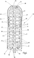
- the illustrated embodiment has a filter housing 2 in the form of a circular cylindrical pot with in Fig. 1 and 2 overhead, closed, arched pot bottom 4 and open lower end 6.
- An end cap screwable at the lower end 6 with an external thread 8 of the housing 2, which is omitted in the figures, has a fluid inlet and a fluid outlet to allow the fluid to be cleaned to flow through an inlet area indicated by a flow arrow 10 ( Fig. 2 ) is to be introduced into the housing 2 and via an outlet area which is marked with a flow arrow 12 ( Fig. 2 ) is designated to be discharged from the housing 2.
- a filter element 14 is received, which has a filter medium 16 forming a hollow cylinder.
- This is preferably pleated and multilayered in the manner customary in such filter devices and extends between one in Fig. 1 and 2 overhead end cap 18 and an end cap 20 at the lower end 6.
- the end caps 18, 20 form in the manner customary in filter devices an enclosure for the front ends of the filter medium 16 and a perforated support tube 22 which rests against the inside of the filter medium 16.
- the lower end cap 20, which has a downwardly protruding connection piece 24 for the fluid connection with the end cap, not shown, is open to the inner filter cavity 25 so that the cleaned fluid can be discharged, as indicated by flow arrow 12.
- the other, upper end cap 18 is in the form of an annular body which, on its upper side 28 facing away from the filter medium 14, has a curvature that is adapted to the curvature of the inside of the pot bottom 4 and, when installed, specifies the centered installation position for the filter element 14.
- the ring body of the end cap 18 has a central passage 30 which, on its inside, forms the seat for a holding device for the compensating element of the filter device.
- the holding device has an inner, round holding body 32 and a holding ring 34 surrounding this on an outer circumferential section.
- the holding body 32 In the assembled state, in which the holding body 32 and holding ring 34 are inserted into the passage 30 of the ring body of the end cap 18, the holding body 32 continues the curvature of the upper side 28 of the end cap 18 with its curved upper side 36, so that the end cap 18 and holding body 32 cover the entire surface rest on the bottom of the pot 4. In the vicinity of the upper side 36, an annular groove 38 is formed in the holding body 32 for a sealing ring 40, which forms the seal of the holding device in the passage 30 of the end cap 18. On the underside facing away from the upper side 36, the holding body 32 forms a flat contact surface 42.
- the holding body 32 has a second annular groove 44, which is adjoined up to the contact surface 42 by a circumferential section 46 with a reduced outer diameter.
- the annular groove 44 together with a recess 48 of the retaining ring 34, forms the seat for defining a thickened edge bead 50 of a compensating element forming membrane 52, which, like the bladder of a bladder hydraulic accumulator, has the shape of an elongated hollow body and is made of one for aggressive fluids, such as aqueous urea solutions, suitable elastomer, such as ethylene propylene diene rubber (EPDM) or hydrogenated acrylonitrile butadiene rubber (HNBR).
- EPDM ethylene propylene diene rubber
- HNBR hydrogenated acrylonitrile butadiene rubber
- the holding body 32 With its flat contact surface 42 and a bushing 54, which extends coaxially away from the contact surface 42 with respect to the longitudinal axis 56 of the device, the holding body 32 forms the holder for a support body 58. in particular Fig. 4 and 5 ) on.
- retaining fingers 60 When retaining fingers 60 are inserted into bushing 54, with retaining fingers 60 fixed, for example, by gluing, support body 58 rests on contact surface 42 of retaining body 32 with a flat end surface 62 that is circular in circumference.
- the retaining ring 34 In this mounting position ( Fig. 1 and 2 ) the retaining ring 34 extends with a ring part 64 protruding beyond the contact surface 42 of the retaining body 32 into the space between the outside of the membrane 52 and the support tube 22 of the filter element 14.
- the support body 58 designed in the manner of a rod body, is composed of a multiplicity of ring segments 66, not all of which are numbered in the figures for the sake of clarity.
- the ring segments 66 run at equal axial distances from one another in a plane perpendicular to the longitudinal axis 56 and are formed from flat flat disks of the same thickness. Only the ring segment 66 closest to the end face 62 and the ring segment 66 closest to the free other end 68 are circular in circumference. In the length sections 70 and 72 (respectively) adjoining the end surface 62 and the other end 68 ( Fig. 1 ) the cross-sectional area of the successive ring segments 66 decreases, with their circumference increasingly deviating from the circular shape.
- the support body 58 has, as in FIG Fig. 1 shown, mainly in the middle section 74 a constricted outer contour.
- a dome-shaped end piece 76 of the outer wall 51 forms a curved contact surface for supporting the membrane 52 at the end of the bladder.
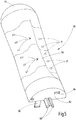
- the support body 58 is composed of two identical halves, which are each formed by a shell body 78 in the form of identical parts.
- segment halves 80 (only partially numbered) form when the shell bodies 78 are at their parting plane 82 ( Fig. 3 and 4th ) abut one another, together the ring segments 66.
- a protruding rib 84 and a groove 86 are formed at two opposite points, which, when the shell bodies 78 lie against one another, engage with one another as fitting elements to form the support body 58.
- a protruding nose 88 and a recess 90 are formed on the end piece 76 as further fitting elements which come into engagement with one another when the shell bodies 78 lie against one another.
- a latching tongue 92 is provided which has a latching hook and protrudes from the parting plane 82 next to the holding fingers 60, and a recess 94 is formed on the opposite side next to the holding fingers 60, in the bottom of which there is a slot 96 which is open at the end face 62.
- the shell bodies 78 When the shell bodies 78 lie against one another, they are locked together by engaging the respective tongue 92 in the associated recess 94 of the other shell body 78, the latching hook of the tongue 92 engaging the slot 96 of the recess 94 of the other shell body 78.
- Fig. 3 shows, form contact webs 98, which extend on diametrically opposite points of the support body 58 along the longitudinal axis 56, support points for the membrane 52.Between the support points, the outer wall 51 of the support body 58 runs according to the outer contour of the support body 58, which, as most clearly in Fig.
- FIG. 1 has a more constricted shape, in particular in the central area, at a locally different distance from the membrane 52, so that from chambers 101 lying between the contact webs 98 a region 100 of different widths in the interior of the membrane 52 as free space for compensatory movements of the membrane 52 is formed, the maximum deflection of the membrane 52 being limited by the support body 58 when the membrane 52 moves in the free space 100 until it rests on the support body 52. How Fig.
- the interior of the support body 58 is divided by the ring segments 66 formed by the subsegments 80 and the contact webs 98 in chambers 27 (not all numbered), which are connected to one another by bores 29, which are also not all numbered and which reach through the subsegments 80 .
- Wall bores (also not all numbered) in the outer wall 51 connect the chambers 27 to the space 100 on the inside of the membrane 52.
Landscapes
- Chemical & Material Sciences (AREA)
- Chemical Kinetics & Catalysis (AREA)
- Engineering & Computer Science (AREA)
- Environmental & Geological Engineering (AREA)
- Exhaust Gas After Treatment (AREA)
Abstract
Description
- Die Erfindung betrifft eine Filtervorrichtung zum Filtern von Fluid, insbesondere in Form einer wässrigen Harnstofflösung, mit einem in einem Filtergehäuse angeordneten Filterelement sowie einem zum Kompensieren von Druck- oder Volumenschwankungen des Fluids vorgesehenen Ausgleichselement in Form eines elastisch nachgiebigen Hohlkörpers, der in einer Richtung eine größere räumliche Ausdehnung hat als quer dazu, der mittels einer Halteeinrichtung im Filtergehäuse gehalten ist und der mit seiner Trennwand eine Trennung zwischen dem Fluid und einem kompressiblen Medium vornimmt.
- Eine Filtervorrichtung der vorstehend genannten Gattung ist im Dokument
DE 10 2015 010 562 A1 offenbart. Wenn solche Filtervorrichtungen in der Automobiltechnik bei den sog. SCR-Abgassystemen zur Anwendung kommen, ermöglicht das Ausgleichselement, die beim Gefrieren der wässrigen Harnstofflösung auftretende Volumenzunahme zu kompensieren, um dergestalt die durch Volumenzunahme bedingten schädlichen Druckeinflüsse auf das empfindliche Filterelementmaterial zu vermeiden, was ansonsten zu Funktionsunfähigkeit der Filtervorrichtung führen könnte, insbesondere wenn durch das Gefrieren des Fluidmaterials das Filterelementmaterial einen Riss oder dergleichen erfährt. Bei der erwähnten, bekannten Lösung ist das Ausgleichselement in Form eines ein kompressibles Medium enthaltenden Hohlkörpers durch eine Blase oder eine Membran gebildet, wie sie auch bei Blasen-Hydrospeichern bzw. Membran-Hydrospeichern Verwendung findet und ein Arbeitsgas, wie N2, enthält. - Ausgehend von diesem Stand der Technik stellt sich die Erfindung die Aufgabe, eine Filtervorrichtung der eingangs genannten Gattung zur Verfügung zu stellen, die sich durch eine hohe Betriebssicherheit über lange Betriebszeiträume auszeichnet.
- Erfindungsgemäß ist diese Aufgabe durch eine Filtervorrichtung gelöst, die die Merkmale des Patentanspruchs 1 in seiner Gesamtheit aufweist.
- Gemäß dem kennzeichnenden Teil des Patentanspruchs 1 besteht eine wesentliche Besonderheit der Erfindung darin, dass innerhalb des Hohlkörpers ein Stützkörper eingebracht ist, der sich von dem Hohlkörper in einer Nicht-Ausgleichsstellung zumindest teilweise in einem Abstand befindet und in mindestens einer Ausgleichsstellung als stützende Anlage für den Hohlkörper dient. Dadurch steht mittels des Stützkörpers ein Entlastungsschutz für die Membran des Hohlkörpers zur Verfügung, durch den beim Ausgleichsvorgang die Verformung der Membran auf einen für die Langzeitfunktion unschädlichen Verformungsgrad begrenzbar ist, bei dem die Membran am Stützkörper zur Anlage kommt. Dadurch ist die Gefahr des Versagens der Membran beseitigt, wie sie bei der bekannten Lösung insbesondere bei sehr tiefen Temperaturen gegeben ist. Da die Filtration bei SCR-Abgassystemen bei mäßigem Fluid-Betriebsdruck erfolgt, steht der Hohlraum der Blase unter einem entsprechend niedrigen Fülldruck, was bei sehr niedrigen Temperaturen zu entsprechend stark abgesunkenem Innendruck und dadurch ungenügender Abstützung der Blase führt. Die sich hieraus ergebenden Risiken einer Überbelastung der Membran sind durch den erfindungsgemäß vorgesehenen, die Maximalverformung der Blase begrenzenden Stützkörper vermieden, so dass erhöhte Betriebssicherheit über lange Betriebszeiträume hinweg gewährleistet ist.
- Bei vorteilhaften Ausführungsbeispielen ist der Stützkörper starr und innen zumindest teilweise mit einem Hohlraum versehen, der über eine medienführende Verbindungseinrichtung mit mindestens einem Raum zwischen Hohl- und Stützkörper verbunden ist, in dem das kompressible Medium aufgenommen ist. Als starrer Körper bildet der Stützkörper eine sichere mechanische Abstützung, während gleichzeitig das Vorhandensein des inneren Hohlraums des Stützkörpers, der mit dem Raum an der Innenseite der Membran in Verbindung steht, auch im Inneren des Stützkörpers ein Gasvolumen zur Verfügung stellt. Dadurch steht, mit Abzug des Wandvolumens des Stützkörpers, die gesamte Innenseite der Blase als Arbeitsgasvolumen zur Verfügung, so dass die Ausgleichseinrichtung mit weicher Kennlinie und damit guter Schutzwirkung für das Filterelement arbeitet.
- Mit Vorteil kann der Stützkörper in der Art eines Stabkörpers ausgebildet und aus einer Vielzahl von einzelnen Ringsegmenten zusammengesetzt sein, die zur Bildung der Verbindungseinrichtung von einzelnen Kanälen durchgriffen sind. Als zusammengesetzter Körper ist der Stützkörper trotz verringertem Werkstoffbedarf mit guter Strukturfestigkeit und mit ausreichendem Innenraum für das Arbeitsgas ausbildbar.
- Mit Vorteil kann die Anordnung so getroffen sein, dass jeweils ein Ringsegment mit seiner einen Hälfte Bestandteil eines Schalenkörpers und mit seiner anderen Hälfte Bestandteil eines weiteren Schalenkörpers ist, die an ihren Stirnseiten zusammengesetzt den Stützkörper ergeben. Solche Teilkörper in Form einseitig offener Schalen mit innerer Ringstruktur lassen sich besonders einfach und rationell, beispielsweise aus Kunststoff, durch Spritzformen herstellen.
- Für die Verbindung der einzelnen Teilvolumina im inneren Hohlraum des Stützkörpers können die einander benachbarten Ringsegmente über mindestens einen Längskanal miteinander medienführend verbunden sein, der ein weiterer Teil der Verbindungseinrichtung ist.
- Mit Vorteil kann der Stützkörper in einem Mittenbereich parallel zu seiner Längsachse und im Querschnitt gesehen diametral einander gegenüberliegende Anlagestege aufweisen, an denen sich der Hohlkörper abstützt. Dadurch sind über die Gesamtlänge des Stützkörpers durchgehende Anlagestellen für die Abstützung der Membran gebildet.
- Mit Vorteil kann die Anordnung hierbei so getroffen sein, dass zwischen den einander benachbarten Anlagestegen und dem Hohlkörper Kammern als Bestandteile des Raumes gebildet sind. Diese stellen Freiräume für die Ausgleichsbewegungen zwischen der Membran des Hohlkörpers und dem Stützkörper zur Verfügung.
- Die Anordnung kann hierbei ferner so getroffen sein, dass der jeweilige Anlagesteg an seinen einander gegenüberliegenden Enden in kreisrunde Umfangsteile des Stützkörpers übergeht. An beiden Längsenden des Stützkörpers bilden diese Umfangsteile daher runde Abschlussstücke.
- Bei vorteilhaften Ausführungsbeispielen trägt das eine Ende des Stützkörpers ein kuppelförmiges Abschlussstück, an dem sich das geschlossene Ende des Hohlkörpers abstützt. Mit seiner Kuppelform bildet dieses Abschlussstück einen Formkörper, der der Blasenform der den Hohlkörper bildenden Membran angepasst ist und die Blase bei fehlendem inneren Gasdruck in ihrer natürlichen Form hält.
- In vorteilhafter Weise, wie dies auch bei Membran-Hydrospeichern üblich ist, kann die Halteeinrichtung für den Hohlkörper einen verdickten Endrand desselben umgreifen und mehrteilig ausgebildet sein. Dadurch ist eine sichere und druckdichte Festlegung der Membran ermöglicht.
- Vorzugsweise ist das Filterelement zylindrisch ausgebildet und stützt sich auf seiner Innenseite an einem perforierten Stützrohr ab, das mit einem vorgebbaren radialen Abstand den Hohlkörper umgibt und mit seiner Länge über den Hohlkörper vorsteht. Während das Stützrohr das Filterelementmaterial im Normalbetrieb gegen die Strömungskraft abstützt, bildet es im Gefrierfall den Schutz des Elementmaterials gegen einen gegebenenfalls trotz des Volumenausgleichs verbleibenden restlichen Gefrierdruck.
- In der bei Filterelementen üblichen Weise kann das Filterelement zwischen zwei Endkappen eingefasst sein, wobei eine Endkappe außenumfangsseitig den Fluideingang mit begrenzt und innenumfangsseitig den Fluidausgang mit umfasst und das eine freie Ende des Stützrohres mit aufnimmt. Dadurch, dass eine Endkappe sowohl den Fluideingang als auch den Fluidausgang bildet, kann die andere Endkappe durch ein einfaches Bauteil gebildet sein, an dem lediglich die Abdichtung gegenüber der Halteeinrichtung ausgebildet sein muss.
- Nachstehend ist die Erfindung anhand eines in der Zeichnung dargestellten Ausführungsbeispiels im Einzelnen erläutert.
- Es zeigen:
- Fig. 1
- eine in Längsrichtung aufgeschnitten gezeichnete perspektivische Schrägansicht des Ausführungsbeispiels der erfindungsgemäßen Filtervorrichtung;
- Fig. 2
- einen Längsschnitt des Ausführungsbeispiels mit gegenüber der Darstellung von
Fig. 1 verdrehter Lage der Schnittebene; - Fig. 3
- eine perspektivische Schrägansicht des auf halber Länge quer geschnittenen Ausführungsbeispiels;
- Fig. 4
- eine perspektivische Schrägansicht eines eine Hälfte des Stützkörpers des Ausführungsbeispiels bildenden Stabkörpers, gesehen auf die offene Schalenseite; und
- Fig. 5
- eine perspektivische Schrägansicht des Stabkörpers von
Fig. 4 , gesehen auf die Schalenaußenseite. - Unter Bezug auf die beigefügten Zeichnungen ist die Erfindung am Beispiel von Filtervorrichtungen beschrieben, die mit besonderem Vorteil bei SCR-Abgassystemen zur Filtration wässriger Harnstofflösungen einsetzbar sind. Das dargestellte Ausführungsbeispiel weist ein Filtergehäuse 2 in Form eines kreiszylindrischen Topfes mit in
Fig. 1 und2 oben liegendem, geschlossenen gewölbten Topfboden 4 und offenem unteren Ende 6 auf. Ein am unteren Ende 6 mit einem Außengewinde 8 des Gehäuses 2 verschraubbarer Abschlussdeckel, der in den Figuren weggelassen ist, weist einen Fluideinlass und einen Fluidauslass aus, um das abzureinigende Fluid über einen Eintrittsbereich, der mit einem Strömungspfeil 10 (Fig. 2 ) bezeichnet ist, in das Gehäuse 2 einzuführen und über einen Austrittsbereich, der mit einem Strömungspfeil 12 (Fig. 2 ) bezeichnet ist, aus dem Gehäuse 2 abzuführen. In letzterem ist ein Filterelement 14 aufgenommen, das ein einen Hohlzylinder bildendes Filtermedium 16 aufweist. Dieses ist in der bei derartigen Filtervorrichtungen üblichen Weise vorzugsweise plissiert und mehrlagig aufgebaut und erstreckt sich zwischen einer inFig. 1 und2 oben liegenden Endkappe 18 und einer Endkappe 20 am unteren Ende 6. Die Endkappen 18, 20 bilden in der bei Filtervorrichtungen üblichen Weise eine Einfassung für die stirnseitigen Enden des Filtermediums 16 sowie eines perforierten Stützrohres 22, das an der Innenseite des Filtermediums 16 anliegt. Die untere Endkappe 20, die einen nach unten vorstehenden Anschlussstutzen 24 für die Fluidverbindung mit dem nicht dargestellten Abschlussdeckel aufweist, ist zum inneren Filterhohlraum 25 offen, so dass das abgereinigte Fluid, wie mit Strömungspfeil 12 angedeutet, abführbar ist. Bei der inFig. 1 und2 gezeigten Einbaulage des Filterelements 14 ist dieses im Gehäuse 2 derart aufgenommen, dass sich die Außenseite des Filtermediums 16 in einem Abstand von der Gehäusewand befindet, so dass ein das Filtermedium 16 umgebender Zwischenraum 26 gebildet ist, der an den inFig. 2 mit Strömungspfeil 10 bezeichneten Fluideinlass angrenzt, so dass der Zwischenraum 26 die Rohseite bei der Filtration bildet. - Die andere, obere Endkappe 18 besitzt die Form eines Ringkörpers, der an seiner vom Filtermedium 14 abgewandten Oberseite 28 eine Wölbung besitzt, die der Wölbung der Innenseite des Topfbodens 4 angepasst ist und im Einbauzustand bei Anlage für das Filterelement 14 die zentrierte Einbaulage vorgibt. Der Ringkörper der Endkappe 18 weist einen zentralen Durchgang 30 auf, der an seiner Innenseite den Sitz für eine Halteeinrichtung für das Ausgleichselement der Filtervorrichtung bildet. Die Halteeinrichtung weist einen inneren, runden Haltekörper 32 und einen diesen auf einem Außenumfangsabschnitt umgebenden Haltering 34 auf. Im Montagezustand, bei dem Haltekörper 32 und Haltering 34 in den Durchgang 30 des Ringkörpers der Endkappe 18 eingesetzt sind, setzt der Haltekörper 32 mit seiner gewölbten Oberseite 36 die Wölbung der Oberseite 28 der Endkappe 18 absatzlos fort, so dass Endkappe 18 und Haltekörper 32 vollflächig am Topfboden 4 anliegen. In der Nähe der Oberseite 36 ist im Haltekörper 32 eine Ringnut 38 für einen Dichtring 40 gebildet, der die Abdichtung der Halteeinrichtung im Durchgang 30 der Endkappe 18 bildet. An der der Oberseite 36 abgewandten Unterseite bildet der Haltekörper 32 eine ebene Anlagefläche 42. In dem Umfangsabschnitt zwischen der Ringnut 38 und der Anlagefläche 42 weist der Haltekörper 32 eine zweite Ringnut 44 auf, an die sich bis zur Anlagefläche 42 ein Umfangsabschnitt 46 mit verringertem Außendurchmesser anschließt. Die Ringnut 44 bildet zusammen mit einer Ausnehmung 48 des Halterings 34 den Sitz zur Festlegung eines verdickten Randwulstes 50 einer das Ausgleichselement bildenden Membran 52, die, wie die Blase eines Blasen-Hydrospeichers die Form eines länglichen Hohlkörpers besitzt und aus einem für aggressive Fluide, wie wässrige Harnstofflösungen, geeigneten Elastomer, wie Ethylen-Propylen-Dien-Kautschuk (EPDM) oder hydriertem Acryl-Nitrilbutadien-Kautschuk (HNBR) besteht.
- Der Haltekörper 32 bildet mit seiner ebenen Anlagefläche 42 und einer Buchse 54, die sich zur Vorrichtungslängsachse 56 koaxial von der Anlagefläche 42 weg erstreckt, die Halterung für einen Stützkörper 58. Dieser weist an seinem der Anlagefläche 42 zugewandten Ende axial vorstehende Haltefinger 60 (s. insbesondere
Fig. 4 und5 ) auf. Bei in die Buchse 54 eingesetzten Haltefingern 60, mit beispielsweise durch Kleben festgelegten Haltefingern 60, liegt der Stützkörper 58 mit ebener und im Umfang kreisrunder Abschlussfläche 62 an der Anlagefläche 42 des Haltekörpers 32 an. In dieser Montageposition (Fig. 1 und2 ) erstreckt sich der Haltering 34 mit einem über die Anlagefläche 42 des Haltekörpers 32 vorstehenden Ringteil 64 in den Zwischenraum zwischen der Außenseite der Membran 52 und dem Stützrohr 22 des Filterelements 14. - Der in der Art eines Stabkörpers ausgebildete Stützkörper 58 ist aus einer Vielzahl von Ringsegmenten 66 zusammengesetzt, die in den Figuren der Übersichtlichkeit wegen nicht sämtliche beziffert sind. Die Ringsegmente 66 verlaufen in gleichen axialen Abständen voneinander in zur Längsachse 56 senkrechter Ebene und sind aus ebenen Flachscheiben gleicher Stärke gebildet. Lediglich das der Abschlussfläche 62 nächstgelegene Ringsegment 66 sowie das dem freien anderen Ende 68 nächstgelegene Ringsegment 66 sind im Umfang kreisrund. In den sich an die Abschlussfläche 62 und an das andere Ende 68 anschließenden Längenabschnitten 70 bzw. 72 (
Fig. 1 ) nimmt die Querschnittsfläche der aufeinanderfolgenden Ringsegmente 66 jeweils ab, wobei ihr Umfang zunehmend von der Kreisform abweicht. Im zwischen den Abschnitten 70 und 72 gelegenem Mittelabschnitt 74 ist die Abweichung von der Kreisform am stärksten und die Querschnittsfläche in Wesentlichen gleichbleibend am geringsten. Mit einer am Umfangsrand der Ringsegmente 66 anliegenden Außenwand 51 besitzt der Stützkörper 58, wie inFig. 1 gezeigt, hauptsächlich im Mittelabschnitt 74 eine eingeschnürte Außenkontur. An dem der Abschlussfläche 62 entgegengesetzten freien Ende 68 bildet ein kuppelförmiges Abschlussstück 76 der Außenwand 51 eine gewölbte Anlagefläche für die Abstützung der Membran 52 am Ende der Blase. - Wie am deutlichsten die
Fig. 4 und5 zeigen, ist der Stützkörper 58 aus zwei gleichen Hälften zusammengesetzt, die je durch einen Schalenkörper 78 in Form von Gleichteilen gebildet sind. In der Öffnung jeder Schale bilden Segmenthälften 80 (nur teilweise beziffert), wenn die Schalenkörper 78 an ihrer Trennebene 82 (Fig. 3 und4 ) aneinanderliegen, zusammen die Ringsegmente 66. An der Trennebene 82 jedes Schalenkörpers 78 sind an zwei einander gegenüberliegenden Stellen eine vorspringende Rippe 84 und eine Nut 86 gebildet, die bei Aneinanderliegen der Schalenkörper 78 zur Bildung des Stützkörpers 58 als Passelemente miteinander in Eingriff sind. Zur Anlagesicherung der aneinanderliegenden Schalenkörper 78 sind am Abschlussstück 76 eine vorstehende Nase 88 und eine Ausnehmung 90 als weitere Passelemente ausgebildet, die bei Aneinanderliegen der Schalenkörper 78 miteinander in Eingriff kommen. Für die Lagesicherung der aneinanderliegenden Schalenkörper 78 gegen Abheben voneinander ist eine einen Rasthaken aufweisende Rastzunge 92 vorgesehen, die neben den Haltefingern 60 aus der Trennebene 82 vorsteht, sowie auf der gegenüberliegenden Seite neben den Haltefingern 60 eine Ausnehmung 94 gebildet, in deren Boden sich ein an der Abschlussfläche 62 offener Schlitz 96 befindet. Bei aneinanderliegenden Schalenkörpern 78 sind diese durch Eingriff der jeweiligen Zunge 92 in die zugehörige Ausnehmung 94 des anderen Schalenkörpers 78, wobei der Rasthaken der Zunge 92 in den Schlitz 96 der Ausnehmung 94 des anderen Schalenkörpers 78 eingreift, miteinander verrastet. - Wie die
Fig. 3 zeigt, bilden Anlagestege 98, die sich auf einander diametral gegenüberliegenden Stellen des Stützkörpers 58 entlang der Längsachse 56 erstrecken, Abstützstellen für die Membran 52. Zwischen den Abstützstellen verläuft die Außenwand 51 des Stützkörpers 58 entsprechend der Außenkontur des Stützkörpers 58, die, wie am deutlichsten inFig. 1 gezeigt ist, eine insbesondere im Mittenbereich stärker eingeschnürte Form besitzt, in örtlich unterschiedlich großem Abstand von der Membran 52, so dass aus zwischen den Anlagestegen 98 liegenden Kammern 101 ein bereichsweise unterschiedlich breiter Raum 100 im Inneren der Membran 52 als Freiraum für Ausgleichsbewegungen der Membran 52 gebildet ist, wobei die Maximalauslenkung der Membran 52 durch den Stützkörper 58 begrenzt ist, wenn sich die Membran 52 in dem freien Raum 100 bis zur Anlage am Stützkörper 52 bewegt. WieFig. 1 ,2 und4 zeigen, ist der Innenraum des Stützkörpers 58 durch die von den Teilsegmenten 80 gebildeten Ringsegmenten 66 und der Anlagestege 98 in Kammern 27 (nicht sämtlich beziffert) abgeteilt, die durch ebenfalls nicht sämtlich bezifferte Bohrungen 29, die die Teilsegmente 80 durchgreifen, miteinander in Verbindung sind. Wandbohrungen (ebenfalls nicht sämtlich beziffert) in der Außenwand 51 verbinden die Kammern 27 mit dem Raum 100 an der Innenseite der Membran 52. Dadurch steht nicht nur das Volumen des Raumes 100, sondern auch das Volumen sämtlicher Kammern 27 im Stützkörper 58 als Volumen für das Arbeitsgas im Innern der das Ausgleichselement bildenden Membran 52 zur Verfügung.
Claims (12)
- Filtervorrichtung zum Filtern von Fluid, insbesondere in Form einer wässrigen Harnstofflösung, mit einem in einem Filtergehäuse (2) angeordneten Filterelement (14) sowie einem zum Kompensieren von Druck- oder Volumenschwankungen des Fluids vorgesehenen Ausgleichselement in Form eines elastisch nachgiebigen Hohlkörpers (52), der in einer Richtung eine größere räumliche Ausdehnung hat als quer dazu, der mittels einer Halteeinrichtung (32, 34) im Filtergehäuse (2) gehalten ist und der mit seiner Trennwand eine Trennung zwischen dem Fluid und einem kompressiblen Medium vornimmt, dadurch gekennzeichnet, dass innerhalb des Hohlkörpers (52) ein Stützkörper (58) eingebracht ist, der sich von dem Hohlkörper (52) in einer Nicht-Ausgleichsstellung zumindest teilweise in einem Abstand befindet und in mindestens einer Ausgleichsstellung als stützende Anlage für den Hohlkörper (52) dient.
- Filtervorrichtung nach Anspruch 1, dadurch gekennzeichnet, dass der Stützkörper (58) starr und innen zumindest teilweise mit einem Hohlraum (27) versehen ist, der über eine medienführende Verbindungseinrichtung (29, 31) mit mindestens einem Raum (100) zwischen Hohl-(52) und Stützkörper (58) verbunden ist, in dem das kompressible Medium aufgenommen ist.
- Filtervorrichtung nach Anspruch 1 oder 2, dadurch gekennzeichnet, dass der Stützkörper (58) in der Art eines Stabkörpers ausgebildet ist und aus einer Vielzahl von einzelnen Ringsegmenten (66) zusammengesetzt ist, die zur Bildung der Verbindungseinrichtung von einzelnen Kanälen (29) durchgriffen sind.
- Filtervorrichtung nach einem der vorstehenden Ansprüche, dadurch gekennzeichnet, dass jeweils ein Ringsegment (66) mit seiner einen Hälfte (80) Bestandteil eines Schalenkörpers (78) und mit seiner anderen Hälfte (80) Bestandteil eines weiteren Schalenkörpers (78) ist, die an ihren Stirnseiten (82) zusammengesetzt den Stützkörper (58) ergeben.
- Filtervorrichtung nach einem der vorstehenden Ansprüche, dadurch gekennzeichnet, dass die einander benachbarten Ringsegmente (66) über mindestens einen Längskanal (29) miteinander medienführend verbunden sind, der ein weiterer Teil der Verbindungseinrichtung (29, 31) ist.
- Filtervorrichtung nach einem der vorstehenden Ansprüche, dadurch gekennzeichnet, dass der Stützkörper (58) in einem Mittenbereich parallel zu seiner Längsachse und im Querschnitt gesehen diametral einander gegenüberliegende Anlagestege (98) aufweist, an denen sich der Hohlkörper (52) abstützt.
- Filtervorrichtung nach einem der vorstehenden Ansprüche, dadurch gekennzeichnet, dass zwischen den einander benachbarten Anlagestegen (98) und dem Hohlkörper (52) Kammern (101) als Bestandteile des Raums (100) gebildet sind.
- Filtervorrichtung nach einem der vorstehenden Ansprüche, dadurch gekennzeichnet, dass der jeweilige Anlagesteg (98) an seinen einander gegenüberliegenden Enden in kreisrunde Umfangsteile (62, 68) des Stützkörpers (58) übergeht.
- Filtervorrichtung nach einem der vorstehenden Ansprüche, dadurch gekennzeichnet, dass das eine Ende des Stützkörpers ein kuppelförmiges Abschlussstück (76) trägt, an dem sich das geschlossene Ende des Hohlkörpers (52) abstützt.
- Filtervorrichtung nach einem der vorstehenden Ansprüche, dadurch gekennzeichnet, dass die Halteeinrichtung (32, 34) für den Hohlkörper (52) einen verdickten Endrand (50) desselben umgreift und mehrteilig ausgebildet ist.
- Filtervorrichtung nach einem der vorstehenden Ansprüche, dadurch gekennzeichnet, dass das Filterelement (14) zylindrisch ausgebildet sich auf seiner Innenseite an einem perforierten Stützrohr (22) abstützt, das mit einem vorgebbaren radialen Abstand den Hohlkörper (52) umgibt und mit seiner Länge über den Hohlkörper (52) vorsteht.
- Filtervorrichtung nach einem der vorstehenden Ansprüche, dadurch gekennzeichnet, dass das Filterelement (14) zwischen zwei Endkappen (18, 20) eingefasst ist und dass die eine Endkappe (20) außenumfangsseitig den Fluideingang (10) mit begrenzt und innenumfangsseitig den Fluidausgang (12) mit umfasst und das eine freie Ende des Stützrohres (22) mit aufnimmt.
Applications Claiming Priority (1)
| Application Number | Priority Date | Filing Date | Title |
|---|---|---|---|
| DE102019006558.1A DE102019006558A1 (de) | 2019-09-17 | 2019-09-17 | Filtervorrichtung |
Publications (2)
| Publication Number | Publication Date |
|---|---|
| EP3795227A1 true EP3795227A1 (de) | 2021-03-24 |
| EP3795227B1 EP3795227B1 (de) | 2022-06-01 |
Family
ID=72087940
Family Applications (1)
| Application Number | Title | Priority Date | Filing Date |
|---|---|---|---|
| EP20191091.6A Active EP3795227B1 (de) | 2019-09-17 | 2020-08-14 | Filtervorrichtung |
Country Status (2)
| Country | Link |
|---|---|
| EP (1) | EP3795227B1 (de) |
| DE (1) | DE102019006558A1 (de) |
Families Citing this family (1)
| Publication number | Priority date | Publication date | Assignee | Title |
|---|---|---|---|---|
| DE102022205625A1 (de) | 2022-06-01 | 2023-12-07 | Robert Bosch Gesellschaft mit beschränkter Haftung | Eisdruck-Kompensationselement |
Citations (3)
| Publication number | Priority date | Publication date | Assignee | Title |
|---|---|---|---|---|
| DE102010027069B3 (de) * | 2010-07-13 | 2012-02-23 | Mann + Hummel Gmbh | Harnstoff-Wasser-Lösung-Filtersystem |
| DE102015010562A1 (de) | 2015-08-12 | 2017-02-16 | Hydac Filtertechnik Gmbh | Filtervorrichtung nebst Filterelement |
| DE102017011278A1 (de) * | 2017-12-07 | 2019-06-13 | Mann+Hummel Gmbh | Volumenausgleichsvorrichtung eines Filters für Harnstoff-Wasser-Lösung und Filter |
Family Cites Families (2)
| Publication number | Priority date | Publication date | Assignee | Title |
|---|---|---|---|---|
| DE102015010533A1 (de) * | 2015-08-12 | 2017-02-16 | Hydac Filtertechnik Gmbh | Filtervorrichtung nebst Filterelement |
| DE102017206184A1 (de) * | 2017-04-11 | 2018-10-11 | Robert Bosch Gmbh | Tankfiltersystem |
-
2019
- 2019-09-17 DE DE102019006558.1A patent/DE102019006558A1/de not_active Withdrawn
-
2020
- 2020-08-14 EP EP20191091.6A patent/EP3795227B1/de active Active
Patent Citations (3)
| Publication number | Priority date | Publication date | Assignee | Title |
|---|---|---|---|---|
| DE102010027069B3 (de) * | 2010-07-13 | 2012-02-23 | Mann + Hummel Gmbh | Harnstoff-Wasser-Lösung-Filtersystem |
| DE102015010562A1 (de) | 2015-08-12 | 2017-02-16 | Hydac Filtertechnik Gmbh | Filtervorrichtung nebst Filterelement |
| DE102017011278A1 (de) * | 2017-12-07 | 2019-06-13 | Mann+Hummel Gmbh | Volumenausgleichsvorrichtung eines Filters für Harnstoff-Wasser-Lösung und Filter |
Also Published As
| Publication number | Publication date |
|---|---|
| DE102019006558A1 (de) | 2021-03-18 |
| EP3795227B1 (de) | 2022-06-01 |
Similar Documents
| Publication | Publication Date | Title |
|---|---|---|
| EP3525913B1 (de) | Rundfilterelement, insbesondere zur gasfiltration | |
| EP0751813B1 (de) | Filterelement mit stützkörper | |
| EP3525910B1 (de) | Filtereinrichtung und rundfilterelement, insbesondere zur gasfiltration | |
| EP0311756B1 (de) | Einfüllstutzen für einen Kraftstoffbehälter eines Kraftfahrzeugs | |
| EP3307414B1 (de) | Filterelement | |
| EP3452203B1 (de) | Ringförmiges filterelement, insbesondere zur gasfiltration | |
| EP3334513B1 (de) | Filtervorrichtung nebst filterelement | |
| EP2845636B1 (de) | Filterelement und Verfahren zur Herstellung eines Filterelements | |
| EP2188564B1 (de) | Dämpfungseinrichtung, insbesondere pulsationsdämpfer | |
| EP3055156B2 (de) | Einfüllstutzen für einen kraftfahrzeug-betriebsflüssigkeitsbehälter | |
| EP2181275B1 (de) | Schutzrohr für ein kolben-zylinderaggregat | |
| EP3334514B1 (de) | Filtervorrichtung | |
| EP3795227B1 (de) | Filtervorrichtung | |
| DE102017011278B4 (de) | Filter für Harnstoff-Wasser-Lösung mit einer Volumenausgleichsvorrichtung | |
| EP4037803B1 (de) | Flüssigkeitsfilter und volumenausgleichs-element für einen flüssigkeitsfilter | |
| DE102016210391A1 (de) | Druckbelastetes Bauteil sowie Verfahren zu dessen Herstellung | |
| EP3334515B1 (de) | Filtervorrichtung | |
| DE3930644A1 (de) | Hydraulisch daempfende buchse | |
| EP2060832B1 (de) | Klemmkontur für ein druckbeaufschlagbares Bauteil und Spannmittel dafür | |
| DE202005002152U1 (de) | Membranventil | |
| DE102019208139A1 (de) | Vorrichtung zur Kompensation einer Volumenänderung eines Fluids bei einem Phasenübergang von flüssig nach fest, Filter und Fördermodul jeweils mit einer solchen Vorrichtung | |
| EP3376188B1 (de) | Messvorrichtung | |
| DE102017006064A1 (de) | Hydrospeicher | |
| WO2013053482A1 (de) | Filtervorrichtung | |
| DE102017207798A1 (de) | Dämpfungsglied zur Reduzierung von Druckschwankungen in einem von einer Flüssigkeit durchströmten Bauteil |
Legal Events
| Date | Code | Title | Description |
|---|---|---|---|
| PUAI | Public reference made under article 153(3) epc to a published international application that has entered the european phase |
Free format text: ORIGINAL CODE: 0009012 |
|
| STAA | Information on the status of an ep patent application or granted ep patent |
Free format text: STATUS: THE APPLICATION HAS BEEN PUBLISHED |
|
| AK | Designated contracting states |
Kind code of ref document: A1 Designated state(s): AL AT BE BG CH CY CZ DE DK EE ES FI FR GB GR HR HU IE IS IT LI LT LU LV MC MK MT NL NO PL PT RO RS SE SI SK SM TR |
|
| AX | Request for extension of the european patent |
Extension state: BA ME |
|
| RAP3 | Party data changed (applicant data changed or rights of an application transferred) |
Owner name: HYDAC FILTERTECHNIK GMBH |
|
| STAA | Information on the status of an ep patent application or granted ep patent |
Free format text: STATUS: REQUEST FOR EXAMINATION WAS MADE |
|
| 17P | Request for examination filed |
Effective date: 20210924 |
|
| RBV | Designated contracting states (corrected) |
Designated state(s): AL AT BE BG CH CY CZ DE DK EE ES FI FR GB GR HR HU IE IS IT LI LT LU LV MC MK MT NL NO PL PT RO RS SE SI SK SM TR |
|
| GRAP | Despatch of communication of intention to grant a patent |
Free format text: ORIGINAL CODE: EPIDOSNIGR1 |
|
| STAA | Information on the status of an ep patent application or granted ep patent |
Free format text: STATUS: GRANT OF PATENT IS INTENDED |
|
| INTG | Intention to grant announced |
Effective date: 20220104 |
|
| GRAS | Grant fee paid |
Free format text: ORIGINAL CODE: EPIDOSNIGR3 |
|
| GRAA | (expected) grant |
Free format text: ORIGINAL CODE: 0009210 |
|
| STAA | Information on the status of an ep patent application or granted ep patent |
Free format text: STATUS: THE PATENT HAS BEEN GRANTED |
|
| AK | Designated contracting states |
Kind code of ref document: B1 Designated state(s): AL AT BE BG CH CY CZ DE DK EE ES FI FR GB GR HR HU IE IS IT LI LT LU LV MC MK MT NL NO PL PT RO RS SE SI SK SM TR |
|
| REG | Reference to a national code |
Ref country code: GB Ref legal event code: FG4D Free format text: NOT ENGLISH |
|
| REG | Reference to a national code |
Ref country code: AT Ref legal event code: REF Ref document number: 1494983 Country of ref document: AT Kind code of ref document: T Effective date: 20220615 Ref country code: CH Ref legal event code: EP Ref country code: DE Ref legal event code: R096 Ref document number: 502020001160 Country of ref document: DE |
|
| REG | Reference to a national code |
Ref country code: IE Ref legal event code: FG4D Free format text: LANGUAGE OF EP DOCUMENT: GERMAN |
|
| REG | Reference to a national code |
Ref country code: LT Ref legal event code: MG9D |
|
| REG | Reference to a national code |
Ref country code: NL Ref legal event code: MP Effective date: 20220601 |
|
| PG25 | Lapsed in a contracting state [announced via postgrant information from national office to epo] |
Ref country code: SE Free format text: LAPSE BECAUSE OF FAILURE TO SUBMIT A TRANSLATION OF THE DESCRIPTION OR TO PAY THE FEE WITHIN THE PRESCRIBED TIME-LIMIT Effective date: 20220601 Ref country code: NO Free format text: LAPSE BECAUSE OF FAILURE TO SUBMIT A TRANSLATION OF THE DESCRIPTION OR TO PAY THE FEE WITHIN THE PRESCRIBED TIME-LIMIT Effective date: 20220901 Ref country code: LT Free format text: LAPSE BECAUSE OF FAILURE TO SUBMIT A TRANSLATION OF THE DESCRIPTION OR TO PAY THE FEE WITHIN THE PRESCRIBED TIME-LIMIT Effective date: 20220601 Ref country code: HR Free format text: LAPSE BECAUSE OF FAILURE TO SUBMIT A TRANSLATION OF THE DESCRIPTION OR TO PAY THE FEE WITHIN THE PRESCRIBED TIME-LIMIT Effective date: 20220601 Ref country code: GR Free format text: LAPSE BECAUSE OF FAILURE TO SUBMIT A TRANSLATION OF THE DESCRIPTION OR TO PAY THE FEE WITHIN THE PRESCRIBED TIME-LIMIT Effective date: 20220902 Ref country code: FI Free format text: LAPSE BECAUSE OF FAILURE TO SUBMIT A TRANSLATION OF THE DESCRIPTION OR TO PAY THE FEE WITHIN THE PRESCRIBED TIME-LIMIT Effective date: 20220601 Ref country code: BG Free format text: LAPSE BECAUSE OF FAILURE TO SUBMIT A TRANSLATION OF THE DESCRIPTION OR TO PAY THE FEE WITHIN THE PRESCRIBED TIME-LIMIT Effective date: 20220901 |
|
| PG25 | Lapsed in a contracting state [announced via postgrant information from national office to epo] |
Ref country code: RS Free format text: LAPSE BECAUSE OF FAILURE TO SUBMIT A TRANSLATION OF THE DESCRIPTION OR TO PAY THE FEE WITHIN THE PRESCRIBED TIME-LIMIT Effective date: 20220601 Ref country code: PL Free format text: LAPSE BECAUSE OF FAILURE TO SUBMIT A TRANSLATION OF THE DESCRIPTION OR TO PAY THE FEE WITHIN THE PRESCRIBED TIME-LIMIT Effective date: 20220601 Ref country code: LV Free format text: LAPSE BECAUSE OF FAILURE TO SUBMIT A TRANSLATION OF THE DESCRIPTION OR TO PAY THE FEE WITHIN THE PRESCRIBED TIME-LIMIT Effective date: 20220601 |
|
| PG25 | Lapsed in a contracting state [announced via postgrant information from national office to epo] |
Ref country code: NL Free format text: LAPSE BECAUSE OF FAILURE TO SUBMIT A TRANSLATION OF THE DESCRIPTION OR TO PAY THE FEE WITHIN THE PRESCRIBED TIME-LIMIT Effective date: 20220601 |
|
| PG25 | Lapsed in a contracting state [announced via postgrant information from national office to epo] |
Ref country code: SM Free format text: LAPSE BECAUSE OF FAILURE TO SUBMIT A TRANSLATION OF THE DESCRIPTION OR TO PAY THE FEE WITHIN THE PRESCRIBED TIME-LIMIT Effective date: 20220601 Ref country code: SK Free format text: LAPSE BECAUSE OF FAILURE TO SUBMIT A TRANSLATION OF THE DESCRIPTION OR TO PAY THE FEE WITHIN THE PRESCRIBED TIME-LIMIT Effective date: 20220601 Ref country code: RO Free format text: LAPSE BECAUSE OF FAILURE TO SUBMIT A TRANSLATION OF THE DESCRIPTION OR TO PAY THE FEE WITHIN THE PRESCRIBED TIME-LIMIT Effective date: 20220601 Ref country code: PT Free format text: LAPSE BECAUSE OF FAILURE TO SUBMIT A TRANSLATION OF THE DESCRIPTION OR TO PAY THE FEE WITHIN THE PRESCRIBED TIME-LIMIT Effective date: 20221003 Ref country code: ES Free format text: LAPSE BECAUSE OF FAILURE TO SUBMIT A TRANSLATION OF THE DESCRIPTION OR TO PAY THE FEE WITHIN THE PRESCRIBED TIME-LIMIT Effective date: 20220601 Ref country code: EE Free format text: LAPSE BECAUSE OF FAILURE TO SUBMIT A TRANSLATION OF THE DESCRIPTION OR TO PAY THE FEE WITHIN THE PRESCRIBED TIME-LIMIT Effective date: 20220601 Ref country code: CZ Free format text: LAPSE BECAUSE OF FAILURE TO SUBMIT A TRANSLATION OF THE DESCRIPTION OR TO PAY THE FEE WITHIN THE PRESCRIBED TIME-LIMIT Effective date: 20220601 |
|
| PG25 | Lapsed in a contracting state [announced via postgrant information from national office to epo] |
Ref country code: IS Free format text: LAPSE BECAUSE OF FAILURE TO SUBMIT A TRANSLATION OF THE DESCRIPTION OR TO PAY THE FEE WITHIN THE PRESCRIBED TIME-LIMIT Effective date: 20221001 |
|
| REG | Reference to a national code |
Ref country code: DE Ref legal event code: R097 Ref document number: 502020001160 Country of ref document: DE |
|
| PG25 | Lapsed in a contracting state [announced via postgrant information from national office to epo] |
Ref country code: MC Free format text: LAPSE BECAUSE OF FAILURE TO SUBMIT A TRANSLATION OF THE DESCRIPTION OR TO PAY THE FEE WITHIN THE PRESCRIBED TIME-LIMIT Effective date: 20220601 Ref country code: AL Free format text: LAPSE BECAUSE OF FAILURE TO SUBMIT A TRANSLATION OF THE DESCRIPTION OR TO PAY THE FEE WITHIN THE PRESCRIBED TIME-LIMIT Effective date: 20220601 |
|
| PLBE | No opposition filed within time limit |
Free format text: ORIGINAL CODE: 0009261 |
|
| STAA | Information on the status of an ep patent application or granted ep patent |
Free format text: STATUS: NO OPPOSITION FILED WITHIN TIME LIMIT |
|
| PG25 | Lapsed in a contracting state [announced via postgrant information from national office to epo] |
Ref country code: LU Free format text: LAPSE BECAUSE OF NON-PAYMENT OF DUE FEES Effective date: 20220814 Ref country code: DK Free format text: LAPSE BECAUSE OF FAILURE TO SUBMIT A TRANSLATION OF THE DESCRIPTION OR TO PAY THE FEE WITHIN THE PRESCRIBED TIME-LIMIT Effective date: 20220601 |
|
| REG | Reference to a national code |
Ref country code: BE Ref legal event code: MM Effective date: 20220831 |
|
| 26N | No opposition filed |
Effective date: 20230302 |
|
| PG25 | Lapsed in a contracting state [announced via postgrant information from national office to epo] |
Ref country code: SI Free format text: LAPSE BECAUSE OF FAILURE TO SUBMIT A TRANSLATION OF THE DESCRIPTION OR TO PAY THE FEE WITHIN THE PRESCRIBED TIME-LIMIT Effective date: 20220601 |
|
| PG25 | Lapsed in a contracting state [announced via postgrant information from national office to epo] |
Ref country code: IE Free format text: LAPSE BECAUSE OF NON-PAYMENT OF DUE FEES Effective date: 20220814 |
|
| PG25 | Lapsed in a contracting state [announced via postgrant information from national office to epo] |
Ref country code: BE Free format text: LAPSE BECAUSE OF NON-PAYMENT OF DUE FEES Effective date: 20220831 |
|
| PG25 | Lapsed in a contracting state [announced via postgrant information from national office to epo] |
Ref country code: IT Free format text: LAPSE BECAUSE OF FAILURE TO SUBMIT A TRANSLATION OF THE DESCRIPTION OR TO PAY THE FEE WITHIN THE PRESCRIBED TIME-LIMIT Effective date: 20220601 |
|
| REG | Reference to a national code |
Ref country code: CH Ref legal event code: PL |
|
| PG25 | Lapsed in a contracting state [announced via postgrant information from national office to epo] |
Ref country code: CY Free format text: LAPSE BECAUSE OF FAILURE TO SUBMIT A TRANSLATION OF THE DESCRIPTION OR TO PAY THE FEE WITHIN THE PRESCRIBED TIME-LIMIT Effective date: 20220601 Ref country code: CH Free format text: LAPSE BECAUSE OF NON-PAYMENT OF DUE FEES Effective date: 20230831 |
|
| PG25 | Lapsed in a contracting state [announced via postgrant information from national office to epo] |
Ref country code: MK Free format text: LAPSE BECAUSE OF FAILURE TO SUBMIT A TRANSLATION OF THE DESCRIPTION OR TO PAY THE FEE WITHIN THE PRESCRIBED TIME-LIMIT Effective date: 20220601 Ref country code: HU Free format text: LAPSE BECAUSE OF FAILURE TO SUBMIT A TRANSLATION OF THE DESCRIPTION OR TO PAY THE FEE WITHIN THE PRESCRIBED TIME-LIMIT; INVALID AB INITIO Effective date: 20200814 |
|
| PG25 | Lapsed in a contracting state [announced via postgrant information from national office to epo] |
Ref country code: TR Free format text: LAPSE BECAUSE OF FAILURE TO SUBMIT A TRANSLATION OF THE DESCRIPTION OR TO PAY THE FEE WITHIN THE PRESCRIBED TIME-LIMIT Effective date: 20220601 |
|
| PG25 | Lapsed in a contracting state [announced via postgrant information from national office to epo] |
Ref country code: MT Free format text: LAPSE BECAUSE OF FAILURE TO SUBMIT A TRANSLATION OF THE DESCRIPTION OR TO PAY THE FEE WITHIN THE PRESCRIBED TIME-LIMIT Effective date: 20220601 |
|
| PG25 | Lapsed in a contracting state [announced via postgrant information from national office to epo] |
Ref country code: BG Free format text: LAPSE BECAUSE OF FAILURE TO SUBMIT A TRANSLATION OF THE DESCRIPTION OR TO PAY THE FEE WITHIN THE PRESCRIBED TIME-LIMIT Effective date: 20220601 |
|
| PG25 | Lapsed in a contracting state [announced via postgrant information from national office to epo] |
Ref country code: BG Free format text: LAPSE BECAUSE OF FAILURE TO SUBMIT A TRANSLATION OF THE DESCRIPTION OR TO PAY THE FEE WITHIN THE PRESCRIBED TIME-LIMIT Effective date: 20220601 |
|
| PGFP | Annual fee paid to national office [announced via postgrant information from national office to epo] |
Ref country code: GB Payment date: 20250611 Year of fee payment: 6 |
|
| PGFP | Annual fee paid to national office [announced via postgrant information from national office to epo] |
Ref country code: DE Payment date: 20250831 Year of fee payment: 6 |
|
| PGFP | Annual fee paid to national office [announced via postgrant information from national office to epo] |
Ref country code: AT Payment date: 20251020 Year of fee payment: 5 Ref country code: FR Payment date: 20250722 Year of fee payment: 6 |