EP3795038A1 - Child care apparatus - Google Patents
Child care apparatus Download PDFInfo
- Publication number
- EP3795038A1 EP3795038A1 EP20196934.2A EP20196934A EP3795038A1 EP 3795038 A1 EP3795038 A1 EP 3795038A1 EP 20196934 A EP20196934 A EP 20196934A EP 3795038 A1 EP3795038 A1 EP 3795038A1
- Authority
- EP
- European Patent Office
- Prior art keywords
- hanging bar
- end portion
- mounting portion
- care apparatus
- child
- Prior art date
- Legal status (The legal status is an assumption and is not a legal conclusion. Google has not performed a legal analysis and makes no representation as to the accuracy of the status listed.)
- Granted
Links
Images






Classifications
-
- A—HUMAN NECESSITIES
- A47—FURNITURE; DOMESTIC ARTICLES OR APPLIANCES; COFFEE MILLS; SPICE MILLS; SUCTION CLEANERS IN GENERAL
- A47D—FURNITURE SPECIALLY ADAPTED FOR CHILDREN
- A47D9/00—Cradles ; Bassinets
- A47D9/02—Cradles ; Bassinets with rocking mechanisms
-
- A—HUMAN NECESSITIES
- A47—FURNITURE; DOMESTIC ARTICLES OR APPLIANCES; COFFEE MILLS; SPICE MILLS; SUCTION CLEANERS IN GENERAL
- A47D—FURNITURE SPECIALLY ADAPTED FOR CHILDREN
- A47D9/00—Cradles ; Bassinets
- A47D9/012—Cradles ; Bassinets with adjustable parts
-
- A—HUMAN NECESSITIES
- A47—FURNITURE; DOMESTIC ARTICLES OR APPLIANCES; COFFEE MILLS; SPICE MILLS; SUCTION CLEANERS IN GENERAL
- A47D—FURNITURE SPECIALLY ADAPTED FOR CHILDREN
- A47D9/00—Cradles ; Bassinets
- A47D9/016—Cradles ; Bassinets capable of being suspended from, or attached to, other articles or structures, e.g. adult's bed
Definitions
- the present invention relates to a child care apparatus having a swingable child support.
- Baby cribs can provide a comfortable and safe environment for sleeping a young child.
- the baby crib may include a child support that can be swung in use.
- some existing baby cribs may have a frame structure that does not allow convenient use as a bedside crib, because the child support is held at a distance not easily accessible for a caregiver resting on an adult bed.
- the present application describes a child care apparatus having hanging bars that can be pivotally supported at different positions, whereby a child support frame held with the hanging bars can be used in different configurations and can have different swinging modes.
- FIGS. 1 and 2 are two perspective views illustrating an embodiment of a child care apparatus 100, which is exemplarily a baby crib.
- the child care apparatus 100 can include a standing frame 102, and a child support frame 104 held on the standing frame 102 via a plurality of hanging bars 106 and 108.
- the standing frame 102 can include two support legs 110 that are spaced apart from each other and can extend generally along an upright direction, and one or more transversal bar 112 connected with the two support legs 110 below the child support frame 104.
- Each support leg 110 can have a lower end connected with a foot portion 114, and an upper end connected with a mounting portion 116.
- the foot portions 114 can provide stable support for the child care apparatus 100 on a floor surface.
- the two mounting portions 116 can be respectively connected fixedly with the two support legs 110.
- each mounting portion 116 can be pivotally connected with two hanging bars 106 and 108, which can extend downward from the mounting portion 116 and can be connected with the child support frame 104 below the mounting portion 116.
- the child support frame 104 provides a rigid support to which a fabric and/or softgoods can be attached to define an interior space suitable to receive a young child.
- the child support frame 104 can include an upper frame portion 118, a lower frame portion 120, and a plurality of upright posts 122 connected with the upper and lower frame portions 118 and 120.
- the upper frame portion 118, the lower frame portion 120 and the upright posts 122 can include a plurality of rigid tubes and/or bars, which can be assembled to define an enclosure frame.
- the child support frame 104 can be placed between the two support legs 110 so that two opposite sides of the child support frame 104 are respectively adjacent to the two support legs 110, and two pairs of hanging bars 106 and 108 can be provided for linking the two opposite sides of the child support frame 104 to the two mounting portions 116 of the support legs 110. More specifically, two hanging bars 106 and 108 can respectively couple each of the two opposite sides of the child support frame 104 to one corresponding mounting portion 116.
- the hanging bar 106 can have two opposite end portions 106A and 106B
- the hanging bar 108 can have two opposite end portions 108A and 108B
- the end portions 106A and 108A can be respectively connected pivotally with the mounting portion 116
- the end portions 106B and 108B can be respectively connected pivotally with the lower frame portion 120 of the child support frame 104.
- the mounting portion 116 can include a housing 124 that is fixedly connected with the support leg 110 at a top thereof, the end portion 106A of the hanging bar 106 and the end portion 108A of the hanging bar 108 can be respectively supported pivotally by the housing 124, and the end portion 106B of the hanging bar 106 and the end portion 108B of the hanging bar 108 can be respectively connected pivotally with the lower frame portion 120 of the child support frame 104. Accordingly, the hanging bars 106 and 108 can hold the child support frame 104 at an elevated position above a floor surface, and are rotatable relative to the standing frame 102 for swinging the child support frame 104 between the two support legs 110.
- the child support frame 104 may be held at an elevated position above a floor surface and protrude higher than the mounting portions 116, which may facilitate access to the child support frame 104 and provide improved visibility. Owing to the pivot connection of the hanging bars 106 and 108 with the child support frame 104, the child support frame 104 may remain in a same horizontal orientation during the swing motion.
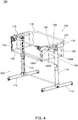
- FIGS. 4-6 are schematic views illustrating an example of construction for coupling the two hanging bars 106 and 108 to the mounting portion 116 at the top of each support leg 110.
- the mounting portion 116 can be configured to allow the end portions 106A and 108A of the hanging bars 106 and 108 to be displaced relative to the mounting portion 116 so that the end portion 106A of the hanging bar 106 is pivotally connected with the mounting portion 116 at a position that is adjustable on the mounting portion 116, and the end portion 108A of the hanging bar 108 is likewise pivotally connected with the mounting portion 116 at a position that is adjustable on the mounting portion 116.
- the housing 124 of the mounting portion 116 can include two receiving slots 130 and 132, the end portion 106A of the hanging bar 106 can be pivotally supported in the receiving slot 130 and adjustable to different positions along the receiving slot 130, and the end portion 108A of the hanging bar 108 can be pivotally supported in the receiving slot 132 and adjustable to different positions along the receiving slot 132.
- each of the end portion 106A of the hanging bar 106 and the end portion 108A of the hanging bar 108 can be connected pivotally and slidably with the mounting portion 116.
- the end portion 106A of the hanging bar 106 can be pivotally supported in and slidable along the receiving slot 130
- the end portion 108A of the hanging bar 108 can be pivotally supported in and slidable along the receiving slot 132.
- the end portions 106A and 108A of the hanging bars 106 and 108 may have any suitable structures adapted to form a movable connection with the receiving slots 130 and 132 of the mounting portion 116.
- the end portion 106A of the hanging bar 106 can have a coupling part 134 fixedly attached thereto that is at least partially disposed in the receiving slot 130, the coupling part 134 being adapted to rotate in the receiving slot 130 and slide along the receiving slot 130.
- the end portion 108A of the hanging bar 108 can have a bend portion that is at least partially disposed in the receiving slot 132, the bend portion being rotatable in the receiving slot 132 and slidable along the receiving slot 132.
- suitable shapes for the aforementioned connection with the receiving slots 130 and 132 may include, without limitation, cylindrical shapes, circular shapes, or spherical shapes.
- the hanging bar 106 can rotate relative to the mounting portion 116, and the end portion 106A of the hanging bar 106 can be placed at different positions along the receiving slot 130, whereby the position where the hanging bar 106 is pivotally supported on the mounting portion 116 can be modified as desired.
- the hanging bar 108 can rotate relative to the mounting portion 116, and the end portion 108A of the hanging bar 108 can be placed at different positions along the receiving slot 132, whereby the position where the hanging bar 108 is pivotally supported on the mounting portion 116 can be modified as desired.
- the receiving slot 130 can generally extend along a horizontal axis, and can be formed as an opening of an elongate shape that is respectively exposed on an inner side of the housing 124 facing the child support frame 104 and an outer side of the housing 124 opposite to the inner side.
- the receiving slot 132 can have an elongate shape generally extending along a horizontal axis, and can be provided on the inner side of the housing 124 facing the child support frame 104. Accordingly, the end portion 106A of the hanging bar 106 and the end portion 108A of the hanging bar 108 can be horizontally adjusted in position on the mounting portion 116.
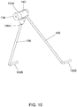
- FIGS. 7-10 are schematic views illustrating an example of construction for the coupling part 134 provided on the hanging bar 106.
- the coupling part 134 may be configurable to fixedly attach together the end portions 106A and 108A of the hanging bars 106 and 108.
- the coupling part 134 can include a housing 134A having an inner cavity 140 that is fixedly attached to the hanging bar 106, and a cover 142 connected with the housing 134A.
- the inner cavity 140 is adapted to at least partially receive the end portion 108A of the hanging bar 108 for fixedly attaching the hanging bars 106 and 108 together.
- the cover 142 can be open for access to the inner cavity 140, and can close over the inner cavity 140.
- the cover 142 may be locked in the closing state by providing a latch 144 on the cover 142 that can engage with a locking groove 146 provided on the housing 134A.
- the coupling part 134 may be assembled with the mounting portion 116 with the housing 134A and the cover 142 of the coupling part 134 protruding outward on the inner side of the mounting portion 116 facing the child support frame 104.
- the coupling part 134 described herein is thus operable to attach or detach the end portions 106A and 108A of the hanging bars 106 and 108 as desired.
- the ability to modify the positions where the end portions 106A and 108A are pivotally supported on the mounting portion 116 can provide different configurations. For example, a distance between the two positions where the end portion 106A of the hanging bar 106 and the end portion 108A of the hanging bar 108 are respectively supported pivotally by the mounting portion 116 may be modified as desired, which may provide different swinging modes for the child support frame 104. Moreover, the child support frame 104 and the hanging bars 106 and 108 may be displaced horizontally as a whole relative to the standing frame 102, which may provide different horizontal positions of the child support frame 104 relative to the standing frame 102.
- FIGS. 11-15 are side views illustrating some examples of configurations for the hanging bars 106 and 108 in the child care apparatus 100.
- the child care apparatus 100 is shown in a configuration where the end portion 106A of the hanging bar 106 and the coupling part 134 thereon are disposed apart from the end portion 108A of the hanging bar 108 on the mounting portion 116, and the hanging bars 106 and 108 are disposed generally parallel to each other.
- a distance D1 between the two positions where the end portion 106A of the hanging bar 106 and the end portion 108A of the hanging bar 108 are respectively supported pivotally by the mounting portion 116 can be substantially equal to a distance D2 between the two locations where the hanging bars 106 and 108 are respectively connected pivotally with the child support frame 104.
- the child support frame 104 can remain in a same horizontal orientation during the swing motion.
- the child care apparatus 100 is shown in another configuration where the end portions 106A and 108A of the hanging bars 106 and 108 are respectively displaced toward each other.
- the distance D1' between the two positions where the end portion 106A of the hanging bar 106 and the end portion 108A of the hanging bar 108 are respectively supported pivotally by the mounting portion 116 can be smaller than the distance D1 in the configuration shown in FIG. 11 , and smaller than the distance D2 between the two locations where the hanging bars 106 and 108 are respectively connected pivotally with the child support frame 104.
- the child support frame 104 may be subjected to a limited swing motion relative to the standing frame 102. Moreover, the child support frame 104 may protrude higher above the mounting portion 116 as the end portion 106A of the hanging bar 106 and the end portion 108A of the hanging bar 108 are positioned closer to each other on the mounting portion 116.
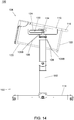
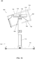
- the child care apparatus 100 is shown in another configuration where the end portions 106A and 108A of the hanging bars 106 and 108 are fixedly attached to each other with the coupling part 134.
- the coupling part 134 with the end portions 106A and 108A of the hanging bars 106 and 108 attached thereto may be restrictedly positioned adjacent to a recess 150 (better shown in FIG. 6 ) provided in the mounting portion 116 between the two receiving slots 130 and 132.
- the coupling part 134 can thereby pivotally couple the hanging bars 106 and 108 to the mounting portion 116.
- the hanging bars 106 and 108 and the coupling part 134 can rotate in unison relative to the mounting portion 116 about a same pivot axis for swinging the child support frame 104, and the inclination of the child support frame 104 may change as it is swung back and forth. This provides a swing mode that differs from that provided by the configurations shown in FIGS. 11 and 12 .
- the child care apparatus described herein include the ability to provide a mounting portion on a standing frame that can pivotally support hanging bars at adjustable positions, whereby a child support frame held with the hanging bars can be used in different configurations and can have different swinging modes. Accordingly, the child care apparatus can offer more flexibility and can be more convenient in use.
Landscapes
- Accommodation For Nursing Or Treatment Tables (AREA)
- Carriages For Children, Sleds, And Other Hand-Operated Vehicles (AREA)
- Invalid Beds And Related Equipment (AREA)
- Handcart (AREA)
- Orthopedics, Nursing, And Contraception (AREA)
- Control And Other Processes For Unpacking Of Materials (AREA)
- Details Of Garments (AREA)
- Bedding Items (AREA)
- Supports Or Holders For Household Use (AREA)
Abstract
Description
- This application claims priority to China patent application no.
201910882253.9 filed on September 18, 2019 - The present invention relates to a child care apparatus having a swingable child support.
- Baby cribs can provide a comfortable and safe environment for sleeping a young child. For helping the child to fall asleep, the baby crib may include a child support that can be swung in use. Unfortunately, some existing baby cribs may have a frame structure that does not allow convenient use as a bedside crib, because the child support is held at a distance not easily accessible for a caregiver resting on an adult bed.
- Therefore, there is a need for a child care apparatus that can be convenient to use, and address at least the foregoing issues.
- The present application describes a child care apparatus having hanging bars that can be pivotally supported at different positions, whereby a child support frame held with the hanging bars can be used in different configurations and can have different swinging modes.
- According to one embodiment, the child care apparatus includes a standing frame including a mounting portion, and a child support frame held on the standing frame via at least one hanging bar that has an end portion pivotally connected with the mounting portion, the hanging bar being rotatable for swinging the child support frame, wherein the end portion of the hanging bar is pivotally connected with the mounting portion at a position that is adjustable on the mounting portion.
-
-
FIG. 1 is a perspective view illustrating an embodiment of a child care apparatus; -
FIG. 2 is another perspective view of the child care apparatus; -
FIG. 3 is a side view illustrating exemplary use of the child care apparatus as a bedside crib; -
FIG. 4 is a perspective view illustrating the child care apparatus including an example of construction for coupling two hanging bars to a mounting portion at a top of a support leg; -
FIG. 5 is another perspective view of the child care apparatus shown inFIG. 4 ; -
FIG. 6 is an enlarged view of portion A shown inFIG. 5 ; -
FIG. 7 is a perspective view illustrating some construction details of two hanging bars provided in the child care apparatus shown inFIG. 4 ; -
FIG. 8 is a perspective view illustrating further construction details of the hanging bars shown inFIG. 7 ; -
FIGS. 9 and10 are two perspective views illustrating how the two hanging bars shown inFIG. 7 can be fixedly attached to each other; -
FIG. 11 is a side view illustrating the child care apparatus in a configuration with the two hanging bars on a same side disposed generally parallel to each other; -
FIG. 12 is a side view illustrating the child care apparatus in another configuration with the upper end portions of the two hanging bars displaced toward each other on the mounting portion; -
FIG. 13 is a side view illustrating the child care apparatus in yet another configuration with the upper end portions of the two hanging bars fixedly attached to each other on the mounting portion; -
FIG. 14 is a side view illustrating the child care apparatus in the configuration shown inFIG. 13 with the child support frame thereof swung to one side; and -
FIG. 15 is a side view illustrating child care apparatus in the configuration shown inFIG. 13 with the child support frame swung to another side. - The present application provides a child care apparatus that includes a standing frame, and a child support frame connected with the standing frame via hanging bars. The standing frame has a mounting portion that can pivotally support hanging bars at adjustable positions, whereby a child support frame held with the hanging bars can be used in different configurations and can have different swinging modes. Embodiments of the child care apparatus described herein include baby cribs. However, it will be appreciated that child care apparatuses that may incorporate the structures and features described herein can include, without limitation, child swings, child rockers, child motion apparatuses, and the like.
-
FIGS. 1 and2 are two perspective views illustrating an embodiment of achild care apparatus 100, which is exemplarily a baby crib. Referring toFIGS. 1 and2 , thechild care apparatus 100 can include a standingframe 102, and achild support frame 104 held on the standingframe 102 via a plurality ofhanging bars frame 102 can include twosupport legs 110 that are spaced apart from each other and can extend generally along an upright direction, and one or moretransversal bar 112 connected with the twosupport legs 110 below thechild support frame 104. Eachsupport leg 110 can have a lower end connected with afoot portion 114, and an upper end connected with amounting portion 116. Thefoot portions 114 can provide stable support for thechild care apparatus 100 on a floor surface. The twomounting portions 116 can be respectively connected fixedly with the twosupport legs 110. Moreover, eachmounting portion 116 can be pivotally connected with twohanging bars mounting portion 116 and can be connected with thechild support frame 104 below themounting portion 116. - Referring to
FIGS. 1 and2 , thechild support frame 104 provides a rigid support to which a fabric and/or softgoods can be attached to define an interior space suitable to receive a young child. According to an example of construction, thechild support frame 104 can include anupper frame portion 118, alower frame portion 120, and a plurality ofupright posts 122 connected with the upper andlower frame portions upper frame portion 118, thelower frame portion 120 and theupright posts 122 can include a plurality of rigid tubes and/or bars, which can be assembled to define an enclosure frame. - According to an example of construction, the
child support frame 104 can be placed between the twosupport legs 110 so that two opposite sides of thechild support frame 104 are respectively adjacent to the twosupport legs 110, and two pairs ofhanging bars child support frame 104 to the twomounting portions 116 of thesupport legs 110. More specifically, twohanging bars child support frame 104 to onecorresponding mounting portion 116. For example, thehanging bar 106 can have twoopposite end portions hanging bar 108 can have twoopposite end portions end portions mounting portion 116, and theend portions lower frame portion 120 of thechild support frame 104. According to an example of construction, themounting portion 116 can include ahousing 124 that is fixedly connected with thesupport leg 110 at a top thereof, theend portion 106A of thehanging bar 106 and theend portion 108A of thehanging bar 108 can be respectively supported pivotally by thehousing 124, and theend portion 106B of thehanging bar 106 and theend portion 108B of thehanging bar 108 can be respectively connected pivotally with thelower frame portion 120 of thechild support frame 104. Accordingly, thehanging bars child support frame 104 at an elevated position above a floor surface, and are rotatable relative to the standingframe 102 for swinging thechild support frame 104 between the twosupport legs 110. According to an example of construction, thechild support frame 104 may be held at an elevated position above a floor surface and protrude higher than themounting portions 116, which may facilitate access to thechild support frame 104 and provide improved visibility. Owing to the pivot connection of thehanging bars child support frame 104, thechild support frame 104 may remain in a same horizontal orientation during the swing motion. - In conjunction with
FIGS. 1 and2 ,FIG. 3 is a side view illustrating exemplary use of thechild care apparatus 100 as a bedside crib. Referring toFIG. 3 , thechild care apparatus 100 can be placed next to a side of anadult bed 80 for use as a bedside crib. A linkingpart 126 may be respectively attached to theadult bed 80 and thechild support frame 104 so as to restrict the position of thechild support frame 104 relative to theadult bed 80 and prevent its swinging. Examples of the linkingpart 124 can include, without limitation, a strap, a belt, a cable, a cord, a rope, a tether, and the like. - In conjunction with
FIGS. 1 and2 ,FIGS. 4-6 are schematic views illustrating an example of construction for coupling the twohanging bars mounting portion 116 at the top of eachsupport leg 110. Referring toFIGS. 4-6 , themounting portion 116 can be configured to allow theend portions hanging bars mounting portion 116 so that theend portion 106A of thehanging bar 106 is pivotally connected with themounting portion 116 at a position that is adjustable on themounting portion 116, and theend portion 108A of thehanging bar 108 is likewise pivotally connected with themounting portion 116 at a position that is adjustable on themounting portion 116. - According to an example of construction, the
housing 124 of themounting portion 116 can include tworeceiving slots end portion 106A of thehanging bar 106 can be pivotally supported in thereceiving slot 130 and adjustable to different positions along thereceiving slot 130, and theend portion 108A of thehanging bar 108 can be pivotally supported in thereceiving slot 132 and adjustable to different positions along thereceiving slot 132. According to an example of construction, each of theend portion 106A of thehanging bar 106 and theend portion 108A of thehanging bar 108 can be connected pivotally and slidably with themounting portion 116. For example, theend portion 106A of thehanging bar 106 can be pivotally supported in and slidable along thereceiving slot 130, and theend portion 108A of thehanging bar 108 can be pivotally supported in and slidable along thereceiving slot 132. - The
end portions hanging bars receiving slots mounting portion 116. According to an example of construction, theend portion 106A of thehanging bar 106 can have acoupling part 134 fixedly attached thereto that is at least partially disposed in thereceiving slot 130, thecoupling part 134 being adapted to rotate in thereceiving slot 130 and slide along thereceiving slot 130. According to an example of construction, theend portion 108A of thehanging bar 108 can have a bend portion that is at least partially disposed in thereceiving slot 132, the bend portion being rotatable in thereceiving slot 132 and slidable along thereceiving slot 132. Examples of suitable shapes for the aforementioned connection with thereceiving slots - With the aforementioned construction, the
hanging bar 106 can rotate relative to themounting portion 116, and theend portion 106A of thehanging bar 106 can be placed at different positions along thereceiving slot 130, whereby the position where thehanging bar 106 is pivotally supported on themounting portion 116 can be modified as desired. Likewise, the hangingbar 108 can rotate relative to the mountingportion 116, and theend portion 108A of the hangingbar 108 can be placed at different positions along the receivingslot 132, whereby the position where the hangingbar 108 is pivotally supported on the mountingportion 116 can be modified as desired. - According to an example of construction, the receiving
slot 130 can generally extend along a horizontal axis, and can be formed as an opening of an elongate shape that is respectively exposed on an inner side of thehousing 124 facing thechild support frame 104 and an outer side of thehousing 124 opposite to the inner side. The receivingslot 132 can have an elongate shape generally extending along a horizontal axis, and can be provided on the inner side of thehousing 124 facing thechild support frame 104. Accordingly, theend portion 106A of the hangingbar 106 and theend portion 108A of the hangingbar 108 can be horizontally adjusted in position on the mountingportion 116. - In conjunction with
FIGS. 4-6 ,FIGS. 7-10 are schematic views illustrating an example of construction for thecoupling part 134 provided on the hangingbar 106. Referring toFIGS. 7-10 , thecoupling part 134 may be configurable to fixedly attach together theend portions bars coupling part 134 can include ahousing 134A having aninner cavity 140 that is fixedly attached to the hangingbar 106, and acover 142 connected with thehousing 134A. Theinner cavity 140 is adapted to at least partially receive theend portion 108A of the hangingbar 108 for fixedly attaching the hangingbars cover 142 can be open for access to theinner cavity 140, and can close over theinner cavity 140. Thecover 142 may be locked in the closing state by providing alatch 144 on thecover 142 that can engage with a lockinggroove 146 provided on thehousing 134A. According to an example of construction, thecoupling part 134 may be assembled with the mountingportion 116 with thehousing 134A and thecover 142 of thecoupling part 134 protruding outward on the inner side of the mountingportion 116 facing thechild support frame 104. Thecoupling part 134 described herein is thus operable to attach or detach theend portions bars - The ability to modify the positions where the
end portions portion 116 can provide different configurations. For example, a distance between the two positions where theend portion 106A of the hangingbar 106 and theend portion 108A of the hangingbar 108 are respectively supported pivotally by the mountingportion 116 may be modified as desired, which may provide different swinging modes for thechild support frame 104. Moreover, thechild support frame 104 and the hangingbars frame 102, which may provide different horizontal positions of thechild support frame 104 relative to the standingframe 102. - In conjunction with
FIGS. 4-10 ,FIGS. 11-15 are side views illustrating some examples of configurations for the hangingbars child care apparatus 100. Referring toFIG. 11 , thechild care apparatus 100 is shown in a configuration where theend portion 106A of the hangingbar 106 and thecoupling part 134 thereon are disposed apart from theend portion 108A of the hangingbar 108 on the mountingportion 116, and the hangingbars FIG. 11 , a distance D1 between the two positions where theend portion 106A of the hangingbar 106 and theend portion 108A of the hangingbar 108 are respectively supported pivotally by the mountingportion 116 can be substantially equal to a distance D2 between the two locations where the hangingbars child support frame 104. When thechild care apparatus 100 is configured as shown inFIG. 11 , thechild support frame 104 can remain in a same horizontal orientation during the swing motion. - Referring to
FIG. 12 , thechild care apparatus 100 is shown in another configuration where theend portions bars FIG. 12 , the distance D1' between the two positions where theend portion 106A of the hangingbar 106 and theend portion 108A of the hangingbar 108 are respectively supported pivotally by the mountingportion 116 can be smaller than the distance D1 in the configuration shown inFIG. 11 , and smaller than the distance D2 between the two locations where the hangingbars child support frame 104. When thechild care apparatus 100 is configured as shown inFIG. 12 , thechild support frame 104 may be subjected to a limited swing motion relative to the standingframe 102. Moreover, thechild support frame 104 may protrude higher above the mountingportion 116 as theend portion 106A of the hangingbar 106 and theend portion 108A of the hangingbar 108 are positioned closer to each other on the mountingportion 116. - Referring to 13-15, the
child care apparatus 100 is shown in another configuration where theend portions bars coupling part 134. Thecoupling part 134 with theend portions bars FIG. 6 ) provided in the mountingportion 116 between the two receivingslots coupling part 134 can thereby pivotally couple the hangingbars portion 116. In the configuration shown inFIGS. 13-15 , the hangingbars coupling part 134 can rotate in unison relative to the mountingportion 116 about a same pivot axis for swinging thechild support frame 104, and the inclination of thechild support frame 104 may change as it is swung back and forth. This provides a swing mode that differs from that provided by the configurations shown inFIGS. 11 and12 . - Advantages of the child care apparatus described herein include the ability to provide a mounting portion on a standing frame that can pivotally support hanging bars at adjustable positions, whereby a child support frame held with the hanging bars can be used in different configurations and can have different swinging modes. Accordingly, the child care apparatus can offer more flexibility and can be more convenient in use.
- Realization of the child care apparatus has been described in the context of particular embodiments. These embodiments are meant to be illustrative and not limiting. Many variations, modifications, additions, and improvements are possible. These and other variations, modifications, additions, and improvements may fall within the scope of the inventions as defined in the claims that follow.
Claims (15)
- A child care apparatus (100) comprising:a standing frame (102) including a mounting portion (116); anda child support frame (104) held on the standing frame (102) via at least one hanging bar (106) that has an end portion (106A) pivotally connected with the mounting portion (116), the hanging bar (106) being rotatable for swinging the child support frame (104);wherein the end portion (106A) of the hanging bar (106) is pivotally connected with the mounting portion (116) at a position that is adjustable on the mounting portion (116).
- The child care apparatus (100) according to claim 1, wherein the position of the end portion (106A) of the hanging bar (106) on the mounting portion (116) is horizontally adjustable.
- The child care apparatus (100) according to claim 1 or 2, wherein the hanging bar (106) is pivotally connected with the child support frame (104).
- The child care apparatus (100) according to claim 1, 2 or 3, wherein the end portion (106A) of the hanging bar (106) is pivotally and slidably connected with the mounting portion (116).
- The child care apparatus (100) according to any of claims 1 to 4, wherein the mounting portion (116) has a receiving slot (130), and the end portion (106A) of the hanging bar (106) is at least partially disposed in the receiving slot (130), the end portion (106A) being rotatable in the receiving slot (130) and adjustable to different positions along the receiving slot (130).
- The child care apparatus (100) according to claim 5, wherein the receiving slot (130) generally extends along a horizontal axis.
- The child care apparatus (100) according to claim 1, further including a second hanging bar (108) that is connected with the child support frame (104) and has an end portion (108A) pivotally connected with the mounting portion (116).
- The child care apparatus (100) according to claim 7, wherein the end portion (108A) of the second hanging bar (108) is pivotally connected with the mounting portion (116) at a position that is adjustable on the mounting portion (116).
- The child care apparatus (100) according to claim 8, wherein a distance between the two positions where the end portion (106A) of the hanging bar (106) and the end portion (108A) of the second hanging bar (108) are respectively supported pivotally by the mounting portion (116) is modifiable.
- The child care apparatus (100) according to claim 8 or 9, wherein the mounting portion (116) includes a first and a second receiving slot (130, 132), the end portion (106A) of the hanging bar (106) is pivotally supported in the first receiving slot (130) and is adjustable to different positions along the first receiving slot (130), and the end portion (108A) of the second hanging bar (108) is pivotally supported in the second receiving slot (132) and is adjustable to different positions along the second receiving slot (132).
- The child care apparatus (100) according to claim 10, wherein the first and second receiving slot (130, 132) generally extend along a horizontal axis.
- The child care apparatus (100) according to any of claims 8 to 11, wherein the end portion (106A) of the hanging bar (106) is fixedly attachable to the end portion (108A) of the second hanging bar (108) with a coupling part (134), the coupling part (134) being adapted to pivotally couple the hanging bar (106) and the second hanging bar (108) to the mounting portion (116).
- The child care apparatus (100) according to claim 12, having a configuration where the end portion (106A) of the hanging bar (106) is fixedly attached to the end portion (108A) of the second hanging bar (108) with the coupling part (134), and the coupling part (134) is at least partially disposed in the mounting portion (116), whereby the coupling part (134), the hanging bar (106) and the second hanging bar (108) are rotatable in unison relative to the mounting portion (116) about a same pivot axis for swinging the child support frame (104).
- The child care apparatus (100) according to claim 12 or 13, wherein the coupling part (134) is provided on the end portion (106A) of the hanging bar (106), and the child care apparatus (100) has a configuration where the end portion (106A) of the hanging bar (106) and the coupling part (134) provided thereon are disposed apart from the end portion (108A) of the second hanging bar (108) on the mounting portion (116).
- The child care apparatus (100) according to any of claims 1 to 14, wherein the child support frame (104) includes an upper frame portion (118), a lower frame portion (120), and a plurality of upright posts (122) connected with the upper and lower frame portions (118, 120), and the hanging bar (106) is pivotally connected with the lower frame portion (120) of the child support frame (104).
Priority Applications (1)
| Application Number | Priority Date | Filing Date | Title |
|---|---|---|---|
| EP23199060.7A EP4272604A3 (en) | 2019-09-18 | 2020-09-18 | Child care apparatus |
Applications Claiming Priority (1)
| Application Number | Priority Date | Filing Date | Title |
|---|---|---|---|
| CN201910882253.9A CN112515410B (en) | 2019-09-18 | 2019-09-18 | Bedside crib |
Related Child Applications (2)
| Application Number | Title | Priority Date | Filing Date |
|---|---|---|---|
| EP23199060.7A Division EP4272604A3 (en) | 2019-09-18 | 2020-09-18 | Child care apparatus |
| EP23199060.7A Division-Into EP4272604A3 (en) | 2019-09-18 | 2020-09-18 | Child care apparatus |
Publications (2)
| Publication Number | Publication Date |
|---|---|
| EP3795038A1 true EP3795038A1 (en) | 2021-03-24 |
| EP3795038B1 EP3795038B1 (en) | 2023-11-01 |
Family
ID=72561670
Family Applications (2)
| Application Number | Title | Priority Date | Filing Date |
|---|---|---|---|
| EP20196934.2A Active EP3795038B1 (en) | 2019-09-18 | 2020-09-18 | Child care apparatus |
| EP23199060.7A Pending EP4272604A3 (en) | 2019-09-18 | 2020-09-18 | Child care apparatus |
Family Applications After (1)
| Application Number | Title | Priority Date | Filing Date |
|---|---|---|---|
| EP23199060.7A Pending EP4272604A3 (en) | 2019-09-18 | 2020-09-18 | Child care apparatus |
Country Status (5)
| Country | Link |
|---|---|
| US (3) | US11419433B2 (en) |
| EP (2) | EP3795038B1 (en) |
| CN (2) | CN112515410B (en) |
| ES (1) | ES2969385T3 (en) |
| TW (2) | TWI827142B (en) |
Families Citing this family (10)
| Publication number | Priority date | Publication date | Assignee | Title |
|---|---|---|---|---|
| CN110811217A (en) * | 2018-08-09 | 2020-02-21 | 穆蒙蒙 | Crib and application thereof |
| CN112515410B (en) * | 2019-09-18 | 2024-09-06 | 明门瑞士股份有限公司 | Bedside crib |
| CN119969788A (en) * | 2021-01-28 | 2025-05-13 | 明门瑞士股份有限公司 | Bracket connection structure, support, baby bed and bed body thereof |
| USD1048789S1 (en) * | 2021-06-01 | 2024-10-29 | Skip Hop, Inc. | Bedside sleeper |
| CN114010007B (en) * | 2021-10-15 | 2024-01-19 | 杨金刚 | Pediatric cradle capable of assisting children to sleep |
| CN116491790A (en) * | 2022-01-18 | 2023-07-28 | 明门(中国)幼童用品有限公司 | crib |
| CN217644908U (en) * | 2022-04-21 | 2022-10-25 | 中山优优贝日用制品有限公司 | Shaking table |
| USD1036882S1 (en) * | 2022-07-08 | 2024-07-30 | Zhongshan City Bobie Baby Product Co., Ltd. | Baby bed |
| USD1028556S1 (en) * | 2022-10-06 | 2024-05-28 | Zhongshan Yongda Baby Products Co.?Ltd. | Crib |
| USD1028593S1 (en) * | 2022-10-17 | 2024-05-28 | Zhongshan M-Castle Childrens Product Co., Ltd. | Foldable bedside sleeper |
Citations (4)
| Publication number | Priority date | Publication date | Assignee | Title |
|---|---|---|---|---|
| GB137633A (en) * | 1919-02-07 | 1920-01-22 | Edwin Lovell | Improvements in or relating to safety enclosures for children |
| CN201085351Y (en) * | 2007-08-22 | 2008-07-16 | 明门实业股份有限公司 | baby swing |
| CN201167750Y (en) * | 2008-02-22 | 2008-12-24 | 明门实业股份有限公司 | Infant swing capable of switching motion modes |
| CN104382420B (en) * | 2014-12-12 | 2017-12-29 | 向显清 | Horizontal reciprocating swing bed for infant |
Family Cites Families (19)
| Publication number | Priority date | Publication date | Assignee | Title |
|---|---|---|---|---|
| CN2285597Y (en) * | 1996-07-31 | 1998-07-08 | 薛碧 | Multifunctional baby health cradle |
| TW450064U (en) * | 2000-11-30 | 2001-08-11 | Chen Shr Tzung | Cradle |
| US20040216229A1 (en) * | 2003-05-02 | 2004-11-04 | Jim Xu | Crib rocking mechanism with lock |
| TWM290008U (en) * | 2005-11-24 | 2006-05-01 | Huang-Guo Liau | Assembled structure of rocking cradle |
| US20090049604A1 (en) * | 2007-08-22 | 2009-02-26 | Xu-Hui Chen | Playard having shade device |
| CN101856183B (en) * | 2009-04-08 | 2013-11-27 | 宝钜(中国)儿童用品有限公司 | Baby crib base mechanism and baby crib employing same |
| CN201542167U (en) * | 2009-11-24 | 2010-08-11 | 张国平 | Multifunctional electric cradle bed |
| CN102283529B (en) * | 2010-06-16 | 2014-08-06 | 明门香港股份有限公司 | crib |
| GB2491613A (en) * | 2011-06-08 | 2012-12-12 | Graham Ian Helm | Rocking crib |
| JP5851786B2 (en) * | 2011-09-29 | 2016-02-03 | アップリカ・チルドレンズプロダクツ合同会社 | Swing bed |
| DE102014016966B4 (en) * | 2014-11-18 | 2018-01-18 | Gerd Frey | Device for storage of infants |
| CN204708424U (en) * | 2015-05-07 | 2015-10-21 | 好孩子儿童用品有限公司 | Cradle |
| ITUB20155758A1 (en) * | 2015-11-20 | 2017-05-20 | Brevi Srl | CRADLE ADHESIVE WITH A BED FOR ADULTS. |
| TWI577316B (en) * | 2016-04-14 | 2017-04-11 | yu-xiang Li | Pneumatic type cuff swing control device |
| CN206576637U (en) * | 2016-08-10 | 2017-10-24 | 顾振翔 | A kind of baby sleeping basket supporting construction |
| CN106539381B (en) * | 2016-12-20 | 2018-08-17 | 华安立高文具制品(深圳)有限公司 | Adjustable for height infanette |
| IT201700008130A1 (en) * | 2017-01-25 | 2018-07-25 | Artsana Spa | Baby cot |
| CN208403890U (en) * | 2017-09-06 | 2019-01-22 | 东莞市鸿硕儿童用品有限公司 | a baby crib |
| CN112515410B (en) * | 2019-09-18 | 2024-09-06 | 明门瑞士股份有限公司 | Bedside crib |
-
2019
- 2019-09-18 CN CN201910882253.9A patent/CN112515410B/en active Active
- 2019-09-18 CN CN202411183079.6A patent/CN118975730A/en active Pending
-
2020
- 2020-09-16 US US17/022,397 patent/US11419433B2/en active Active
- 2020-09-17 TW TW111126613A patent/TWI827142B/en active
- 2020-09-17 TW TW109132115A patent/TWI774065B/en active
- 2020-09-18 EP EP20196934.2A patent/EP3795038B1/en active Active
- 2020-09-18 ES ES20196934T patent/ES2969385T3/en active Active
- 2020-09-18 EP EP23199060.7A patent/EP4272604A3/en active Pending
-
2022
- 2022-07-14 US US17/864,650 patent/US12053103B2/en active Active
-
2024
- 2024-07-02 US US18/762,288 patent/US20240349909A1/en active Pending
Patent Citations (4)
| Publication number | Priority date | Publication date | Assignee | Title |
|---|---|---|---|---|
| GB137633A (en) * | 1919-02-07 | 1920-01-22 | Edwin Lovell | Improvements in or relating to safety enclosures for children |
| CN201085351Y (en) * | 2007-08-22 | 2008-07-16 | 明门实业股份有限公司 | baby swing |
| CN201167750Y (en) * | 2008-02-22 | 2008-12-24 | 明门实业股份有限公司 | Infant swing capable of switching motion modes |
| CN104382420B (en) * | 2014-12-12 | 2017-12-29 | 向显清 | Horizontal reciprocating swing bed for infant |
Also Published As
| Publication number | Publication date |
|---|---|
| US20220346568A1 (en) | 2022-11-03 |
| US12053103B2 (en) | 2024-08-06 |
| EP4272604A3 (en) | 2024-03-20 |
| US20210076842A1 (en) | 2021-03-18 |
| TWI774065B (en) | 2022-08-11 |
| TW202116232A (en) | 2021-05-01 |
| TW202241318A (en) | 2022-11-01 |
| US20240349909A1 (en) | 2024-10-24 |
| CN118975730A (en) | 2024-11-19 |
| CN112515410A (en) | 2021-03-19 |
| TWI827142B (en) | 2023-12-21 |
| ES2969385T3 (en) | 2024-05-17 |
| EP4272604A2 (en) | 2023-11-08 |
| CN112515410B (en) | 2024-09-06 |
| US11419433B2 (en) | 2022-08-23 |
| EP3795038B1 (en) | 2023-11-01 |
Similar Documents
| Publication | Publication Date | Title |
|---|---|---|
| US12053103B2 (en) | Child care apparatus | |
| US11864668B2 (en) | Child containment system with multiple infant support modes | |
| US6233759B1 (en) | Combination folding play pen with changing table and bassinet | |
| US8677526B2 (en) | Baby crib | |
| CN201171525Y (en) | Baby chair | |
| CN101427875B (en) | Crib with oval changing table installed along the centerline | |
| US20090113625A1 (en) | Play Yard with Motorized Swinging Bassinet | |
| TW201729733A (en) | Baby crib | |
| US20100263121A1 (en) | Convertible bassinet | |
| GB2512194A (en) | Reversible infant supporting apparatus | |
| TW202222214A (en) | Child bassinet | |
| CN103960917A (en) | baby support device | |
| CN205457572U (en) | Baby Carrier Structures and Rocking Baby Carriers | |
| JP2006034620A (en) | Bed | |
| GB2421684A (en) | Stand for a baby's cot including a stanchion and floor-engaging feet such that the stand is mounted for at least horizontal movement relative to the stanchion | |
| WO2025006576A1 (en) | Bassinet connectable to a playard and playard assembly | |
| WO2020013068A1 (en) | Folding bed |
Legal Events
| Date | Code | Title | Description |
|---|---|---|---|
| PUAI | Public reference made under article 153(3) epc to a published international application that has entered the european phase |
Free format text: ORIGINAL CODE: 0009012 |
|
| STAA | Information on the status of an ep patent application or granted ep patent |
Free format text: STATUS: REQUEST FOR EXAMINATION WAS MADE |
|
| 17P | Request for examination filed |
Effective date: 20200918 |
|
| AK | Designated contracting states |
Kind code of ref document: A1 Designated state(s): AL AT BE BG CH CY CZ DE DK EE ES FI FR GB GR HR HU IE IS IT LI LT LU LV MC MK MT NL NO PL PT RO RS SE SI SK SM TR |
|
| AX | Request for extension of the european patent |
Extension state: BA ME |
|
| RBV | Designated contracting states (corrected) |
Designated state(s): AL AT BE BG CH CY CZ DE DK EE ES FI FR GB GR HR HU IE IS IT LI LT LU LV MC MK MT NL NO PL PT RO RS SE SI SK SM TR |
|
| GRAP | Despatch of communication of intention to grant a patent |
Free format text: ORIGINAL CODE: EPIDOSNIGR1 |
|
| STAA | Information on the status of an ep patent application or granted ep patent |
Free format text: STATUS: GRANT OF PATENT IS INTENDED |
|
| INTG | Intention to grant announced |
Effective date: 20230522 |
|
| P01 | Opt-out of the competence of the unified patent court (upc) registered |
Effective date: 20230530 |
|
| GRAS | Grant fee paid |
Free format text: ORIGINAL CODE: EPIDOSNIGR3 |
|
| GRAA | (expected) grant |
Free format text: ORIGINAL CODE: 0009210 |
|
| STAA | Information on the status of an ep patent application or granted ep patent |
Free format text: STATUS: THE PATENT HAS BEEN GRANTED |
|
| AK | Designated contracting states |
Kind code of ref document: B1 Designated state(s): AL AT BE BG CH CY CZ DE DK EE ES FI FR GB GR HR HU IE IS IT LI LT LU LV MC MK MT NL NO PL PT RO RS SE SI SK SM TR |
|
| REG | Reference to a national code |
Ref country code: GB Ref legal event code: FG4D |
|
| REG | Reference to a national code |
Ref country code: CH Ref legal event code: EP |
|
| REG | Reference to a national code |
Ref country code: IE Ref legal event code: FG4D |
|
| REG | Reference to a national code |
Ref country code: DE Ref legal event code: R096 Ref document number: 602020020152 Country of ref document: DE |
|
| REG | Reference to a national code |
Ref country code: NL Ref legal event code: FP |
|
| REG | Reference to a national code |
Ref country code: LT Ref legal event code: MG9D |
|
| PG25 | Lapsed in a contracting state [announced via postgrant information from national office to epo] |
Ref country code: GR Free format text: LAPSE BECAUSE OF FAILURE TO SUBMIT A TRANSLATION OF THE DESCRIPTION OR TO PAY THE FEE WITHIN THE PRESCRIBED TIME-LIMIT Effective date: 20240202 |
|
| PG25 | Lapsed in a contracting state [announced via postgrant information from national office to epo] |
Ref country code: IS Free format text: LAPSE BECAUSE OF FAILURE TO SUBMIT A TRANSLATION OF THE DESCRIPTION OR TO PAY THE FEE WITHIN THE PRESCRIBED TIME-LIMIT Effective date: 20240301 |
|
| PG25 | Lapsed in a contracting state [announced via postgrant information from national office to epo] |
Ref country code: LT Free format text: LAPSE BECAUSE OF FAILURE TO SUBMIT A TRANSLATION OF THE DESCRIPTION OR TO PAY THE FEE WITHIN THE PRESCRIBED TIME-LIMIT Effective date: 20231101 |
|
| REG | Reference to a national code |
Ref country code: AT Ref legal event code: MK05 Ref document number: 1626202 Country of ref document: AT Kind code of ref document: T Effective date: 20231101 |
|
| PG25 | Lapsed in a contracting state [announced via postgrant information from national office to epo] |
Ref country code: AT Free format text: LAPSE BECAUSE OF FAILURE TO SUBMIT A TRANSLATION OF THE DESCRIPTION OR TO PAY THE FEE WITHIN THE PRESCRIBED TIME-LIMIT Effective date: 20231101 |
|
| PG25 | Lapsed in a contracting state [announced via postgrant information from national office to epo] |
Ref country code: LT Free format text: LAPSE BECAUSE OF FAILURE TO SUBMIT A TRANSLATION OF THE DESCRIPTION OR TO PAY THE FEE WITHIN THE PRESCRIBED TIME-LIMIT Effective date: 20231101 Ref country code: IS Free format text: LAPSE BECAUSE OF FAILURE TO SUBMIT A TRANSLATION OF THE DESCRIPTION OR TO PAY THE FEE WITHIN THE PRESCRIBED TIME-LIMIT Effective date: 20240301 Ref country code: GR Free format text: LAPSE BECAUSE OF FAILURE TO SUBMIT A TRANSLATION OF THE DESCRIPTION OR TO PAY THE FEE WITHIN THE PRESCRIBED TIME-LIMIT Effective date: 20240202 Ref country code: BG Free format text: LAPSE BECAUSE OF FAILURE TO SUBMIT A TRANSLATION OF THE DESCRIPTION OR TO PAY THE FEE WITHIN THE PRESCRIBED TIME-LIMIT Effective date: 20240201 Ref country code: AT Free format text: LAPSE BECAUSE OF FAILURE TO SUBMIT A TRANSLATION OF THE DESCRIPTION OR TO PAY THE FEE WITHIN THE PRESCRIBED TIME-LIMIT Effective date: 20231101 Ref country code: PT Free format text: LAPSE BECAUSE OF FAILURE TO SUBMIT A TRANSLATION OF THE DESCRIPTION OR TO PAY THE FEE WITHIN THE PRESCRIBED TIME-LIMIT Effective date: 20240301 |
|
| REG | Reference to a national code |
Ref country code: ES Ref legal event code: FG2A Ref document number: 2969385 Country of ref document: ES Kind code of ref document: T3 Effective date: 20240517 |
|
| PG25 | Lapsed in a contracting state [announced via postgrant information from national office to epo] |
Ref country code: SE Free format text: LAPSE BECAUSE OF FAILURE TO SUBMIT A TRANSLATION OF THE DESCRIPTION OR TO PAY THE FEE WITHIN THE PRESCRIBED TIME-LIMIT Effective date: 20231101 Ref country code: RS Free format text: LAPSE BECAUSE OF FAILURE TO SUBMIT A TRANSLATION OF THE DESCRIPTION OR TO PAY THE FEE WITHIN THE PRESCRIBED TIME-LIMIT Effective date: 20231101 Ref country code: PL Free format text: LAPSE BECAUSE OF FAILURE TO SUBMIT A TRANSLATION OF THE DESCRIPTION OR TO PAY THE FEE WITHIN THE PRESCRIBED TIME-LIMIT Effective date: 20231101 Ref country code: NO Free format text: LAPSE BECAUSE OF FAILURE TO SUBMIT A TRANSLATION OF THE DESCRIPTION OR TO PAY THE FEE WITHIN THE PRESCRIBED TIME-LIMIT Effective date: 20240201 Ref country code: LV Free format text: LAPSE BECAUSE OF FAILURE TO SUBMIT A TRANSLATION OF THE DESCRIPTION OR TO PAY THE FEE WITHIN THE PRESCRIBED TIME-LIMIT Effective date: 20231101 Ref country code: HR Free format text: LAPSE BECAUSE OF FAILURE TO SUBMIT A TRANSLATION OF THE DESCRIPTION OR TO PAY THE FEE WITHIN THE PRESCRIBED TIME-LIMIT Effective date: 20231101 |
|
| PG25 | Lapsed in a contracting state [announced via postgrant information from national office to epo] |
Ref country code: DK Free format text: LAPSE BECAUSE OF FAILURE TO SUBMIT A TRANSLATION OF THE DESCRIPTION OR TO PAY THE FEE WITHIN THE PRESCRIBED TIME-LIMIT Effective date: 20231101 |
|
| PG25 | Lapsed in a contracting state [announced via postgrant information from national office to epo] |
Ref country code: CZ Free format text: LAPSE BECAUSE OF FAILURE TO SUBMIT A TRANSLATION OF THE DESCRIPTION OR TO PAY THE FEE WITHIN THE PRESCRIBED TIME-LIMIT Effective date: 20231101 |
|
| PG25 | Lapsed in a contracting state [announced via postgrant information from national office to epo] |
Ref country code: SK Free format text: LAPSE BECAUSE OF FAILURE TO SUBMIT A TRANSLATION OF THE DESCRIPTION OR TO PAY THE FEE WITHIN THE PRESCRIBED TIME-LIMIT Effective date: 20231101 |
|
| PG25 | Lapsed in a contracting state [announced via postgrant information from national office to epo] |
Ref country code: SM Free format text: LAPSE BECAUSE OF FAILURE TO SUBMIT A TRANSLATION OF THE DESCRIPTION OR TO PAY THE FEE WITHIN THE PRESCRIBED TIME-LIMIT Effective date: 20231101 Ref country code: SK Free format text: LAPSE BECAUSE OF FAILURE TO SUBMIT A TRANSLATION OF THE DESCRIPTION OR TO PAY THE FEE WITHIN THE PRESCRIBED TIME-LIMIT Effective date: 20231101 Ref country code: IT Free format text: LAPSE BECAUSE OF FAILURE TO SUBMIT A TRANSLATION OF THE DESCRIPTION OR TO PAY THE FEE WITHIN THE PRESCRIBED TIME-LIMIT Effective date: 20231101 Ref country code: EE Free format text: LAPSE BECAUSE OF FAILURE TO SUBMIT A TRANSLATION OF THE DESCRIPTION OR TO PAY THE FEE WITHIN THE PRESCRIBED TIME-LIMIT Effective date: 20231101 Ref country code: DK Free format text: LAPSE BECAUSE OF FAILURE TO SUBMIT A TRANSLATION OF THE DESCRIPTION OR TO PAY THE FEE WITHIN THE PRESCRIBED TIME-LIMIT Effective date: 20231101 Ref country code: CZ Free format text: LAPSE BECAUSE OF FAILURE TO SUBMIT A TRANSLATION OF THE DESCRIPTION OR TO PAY THE FEE WITHIN THE PRESCRIBED TIME-LIMIT Effective date: 20231101 |
|
| REG | Reference to a national code |
Ref country code: DE Ref legal event code: R097 Ref document number: 602020020152 Country of ref document: DE |
|
| PLBE | No opposition filed within time limit |
Free format text: ORIGINAL CODE: 0009261 |
|
| STAA | Information on the status of an ep patent application or granted ep patent |
Free format text: STATUS: NO OPPOSITION FILED WITHIN TIME LIMIT |
|
| 26N | No opposition filed |
Effective date: 20240802 |
|
| PG25 | Lapsed in a contracting state [announced via postgrant information from national office to epo] |
Ref country code: SI Free format text: LAPSE BECAUSE OF FAILURE TO SUBMIT A TRANSLATION OF THE DESCRIPTION OR TO PAY THE FEE WITHIN THE PRESCRIBED TIME-LIMIT Effective date: 20231101 |
|
| PG25 | Lapsed in a contracting state [announced via postgrant information from national office to epo] |
Ref country code: SI Free format text: LAPSE BECAUSE OF FAILURE TO SUBMIT A TRANSLATION OF THE DESCRIPTION OR TO PAY THE FEE WITHIN THE PRESCRIBED TIME-LIMIT Effective date: 20231101 |
|
| PG25 | Lapsed in a contracting state [announced via postgrant information from national office to epo] |
Ref country code: MC Free format text: LAPSE BECAUSE OF FAILURE TO SUBMIT A TRANSLATION OF THE DESCRIPTION OR TO PAY THE FEE WITHIN THE PRESCRIBED TIME-LIMIT Effective date: 20231101 |
|
| PG25 | Lapsed in a contracting state [announced via postgrant information from national office to epo] |
Ref country code: LU Free format text: LAPSE BECAUSE OF NON-PAYMENT OF DUE FEES Effective date: 20240918 |
|
| REG | Reference to a national code |
Ref country code: BE Ref legal event code: MM Effective date: 20240930 |
|
| PG25 | Lapsed in a contracting state [announced via postgrant information from national office to epo] |
Ref country code: BE Free format text: LAPSE BECAUSE OF NON-PAYMENT OF DUE FEES Effective date: 20240930 |
|
| PG25 | Lapsed in a contracting state [announced via postgrant information from national office to epo] |
Ref country code: IE Free format text: LAPSE BECAUSE OF NON-PAYMENT OF DUE FEES Effective date: 20240918 |
|
| REG | Reference to a national code |
Ref country code: CH Ref legal event code: U11 Free format text: ST27 STATUS EVENT CODE: U-0-0-U10-U11 (AS PROVIDED BY THE NATIONAL OFFICE) Effective date: 20251001 |
|
| PG25 | Lapsed in a contracting state [announced via postgrant information from national office to epo] |
Ref country code: FI Free format text: LAPSE BECAUSE OF FAILURE TO SUBMIT A TRANSLATION OF THE DESCRIPTION OR TO PAY THE FEE WITHIN THE PRESCRIBED TIME-LIMIT Effective date: 20231101 |
|
| PGFP | Annual fee paid to national office [announced via postgrant information from national office to epo] |
Ref country code: DE Payment date: 20250807 Year of fee payment: 6 |
|
| PGFP | Annual fee paid to national office [announced via postgrant information from national office to epo] |
Ref country code: NL Payment date: 20250925 Year of fee payment: 6 |
|
| PGFP | Annual fee paid to national office [announced via postgrant information from national office to epo] |
Ref country code: GB Payment date: 20250814 Year of fee payment: 6 |
|
| PGFP | Annual fee paid to national office [announced via postgrant information from national office to epo] |
Ref country code: FR Payment date: 20250814 Year of fee payment: 6 |
|
| PG25 | Lapsed in a contracting state [announced via postgrant information from national office to epo] |
Ref country code: RO Free format text: LAPSE BECAUSE OF FAILURE TO SUBMIT A TRANSLATION OF THE DESCRIPTION OR TO PAY THE FEE WITHIN THE PRESCRIBED TIME-LIMIT Effective date: 20231101 |
|
| PGFP | Annual fee paid to national office [announced via postgrant information from national office to epo] |
Ref country code: CH Payment date: 20251001 Year of fee payment: 6 |
|
| PG25 | Lapsed in a contracting state [announced via postgrant information from national office to epo] |
Ref country code: CY Free format text: LAPSE BECAUSE OF FAILURE TO SUBMIT A TRANSLATION OF THE DESCRIPTION OR TO PAY THE FEE WITHIN THE PRESCRIBED TIME-LIMIT; INVALID AB INITIO Effective date: 20200918 |
|
| PGFP | Annual fee paid to national office [announced via postgrant information from national office to epo] |
Ref country code: ES Payment date: 20251015 Year of fee payment: 6 |
|
| PG25 | Lapsed in a contracting state [announced via postgrant information from national office to epo] |
Ref country code: HU Free format text: LAPSE BECAUSE OF FAILURE TO SUBMIT A TRANSLATION OF THE DESCRIPTION OR TO PAY THE FEE WITHIN THE PRESCRIBED TIME-LIMIT; INVALID AB INITIO Effective date: 20200918 |