EP3794861B1 - Performance simulation of a distributed mimo antenna system - Google Patents
Performance simulation of a distributed mimo antenna system Download PDFInfo
- Publication number
- EP3794861B1 EP3794861B1 EP19728519.0A EP19728519A EP3794861B1 EP 3794861 B1 EP3794861 B1 EP 3794861B1 EP 19728519 A EP19728519 A EP 19728519A EP 3794861 B1 EP3794861 B1 EP 3794861B1
- Authority
- EP
- European Patent Office
- Prior art keywords
- rank
- cell
- antenna deployment
- antenna
- determining
- Prior art date
- Legal status (The legal status is an assumption and is not a legal conclusion. Google has not performed a legal analysis and makes no representation as to the accuracy of the status listed.)
- Active
Links
- 238000004088 simulation Methods 0.000 title description 7
- 238000000034 method Methods 0.000 claims description 37
- 238000012545 processing Methods 0.000 claims description 26
- 230000001186 cumulative effect Effects 0.000 claims description 15
- 238000013507 mapping Methods 0.000 claims 1
- 238000013461 design Methods 0.000 description 11
- 230000006870 function Effects 0.000 description 9
- 238000004891 communication Methods 0.000 description 8
- 238000010586 diagram Methods 0.000 description 6
- 239000000463 material Substances 0.000 description 4
- 230000008569 process Effects 0.000 description 4
- 230000008901 benefit Effects 0.000 description 3
- 238000004590 computer program Methods 0.000 description 2
- 230000010354 integration Effects 0.000 description 2
- 230000003287 optical effect Effects 0.000 description 2
- 230000001105 regulatory effect Effects 0.000 description 2
- 238000012800 visualization Methods 0.000 description 2
- 238000013459 approach Methods 0.000 description 1
- 238000003491 array Methods 0.000 description 1
- 238000004422 calculation algorithm Methods 0.000 description 1
- 238000004364 calculation method Methods 0.000 description 1
- 238000006243 chemical reaction Methods 0.000 description 1
- 239000003086 colorant Substances 0.000 description 1
- 230000001419 dependent effect Effects 0.000 description 1
- 230000000694 effects Effects 0.000 description 1
- 230000008676 import Effects 0.000 description 1
- 238000005457 optimization Methods 0.000 description 1
- 230000011664 signaling Effects 0.000 description 1
- 238000012360 testing method Methods 0.000 description 1
Images


Classifications
-
- H—ELECTRICITY
- H04—ELECTRIC COMMUNICATION TECHNIQUE
- H04W—WIRELESS COMMUNICATION NETWORKS
- H04W16/00—Network planning, e.g. coverage or traffic planning tools; Network deployment, e.g. resource partitioning or cells structures
- H04W16/18—Network planning tools
- H04W16/20—Network planning tools for indoor coverage or short range network deployment
-
- H—ELECTRICITY
- H04—ELECTRIC COMMUNICATION TECHNIQUE
- H04W—WIRELESS COMMUNICATION NETWORKS
- H04W16/00—Network planning, e.g. coverage or traffic planning tools; Network deployment, e.g. resource partitioning or cells structures
- H04W16/18—Network planning tools
-
- H—ELECTRICITY
- H04—ELECTRIC COMMUNICATION TECHNIQUE
- H04B—TRANSMISSION
- H04B17/00—Monitoring; Testing
- H04B17/30—Monitoring; Testing of propagation channels
- H04B17/309—Measuring or estimating channel quality parameters
- H04B17/336—Signal-to-interference ratio [SIR] or carrier-to-interference ratio [CIR]
-
- H—ELECTRICITY
- H04—ELECTRIC COMMUNICATION TECHNIQUE
- H04B—TRANSMISSION
- H04B7/00—Radio transmission systems, i.e. using radiation field
- H04B7/02—Diversity systems; Multi-antenna system, i.e. transmission or reception using multiple antennas
- H04B7/04—Diversity systems; Multi-antenna system, i.e. transmission or reception using multiple antennas using two or more spaced independent antennas
- H04B7/0413—MIMO systems
Definitions
- the disclosure relates to designing wireless communications, and in particular, to designing Multiple-Input and Multiple-Output (MIMO) networks.
- MIMO Multiple-Input and Multiple-Output
- Planning products can be used to design network deployments. Some enable the automation of some of the planning process, significantly reducing planning times. Some planning products enable users to import a floor plan and use it to create a plan for the locations of network products and associated cabling. Users can modify several floor attributes including wall materials and structures to produce more accurate planning results. Users can also modify node locations to suit their own situation. Output from the tool sometimes includes a coverage report, a Bill of Materials to help in ordering, and a solution report listing the required hardware and cabling on each floor of the building.
- MIMO Multiple-Input and Multiple-Output
- Document US 2013/0183961 A1 discloses a method and system for communication network design.
- the method includes generating, by a computer processor, a plurality of receiver points and generating a target received signal strength for each receiver point of the plurality of receiver points.
- the method further includes determining a predicted number of antennas based on a size of the communications network and a coverage area of an antenna, and determining a location for each antenna of the predicted number of antennas.
- the method still further includes generating an estimated received signal strength for each receiver point of the plurality of receiver points, based upon the predicted number of antennas and upon the location of each antenna of the predicted number of antennas.
- the method also includes comparing the estimated received signal strength for each receiver point with the target received signal strength for the receiver point and generating a revised predicted number of antennas based upon at least one of the comparisons of target received signal strength and estimated received signal strength.
- Document CN 102 098 689 A discloses an automatic antenna distribution method and an automatic antenna distribution system for an indoor distributed wireless network.
- the method comprises the following steps of: 1, initializing the antenna distribution density and antenna distribution positions of the indoor distributed wireless network to be distributed; 2, simulating current distribution by using a preset propagation model; 3, judging whether a coverage simulation result meets the requirements of a preset coverage objective or not, performing a step 4 if the coverage simulation result does not meet the requirements of the preset coverage objective, and finishing the arrangement if the coverage simulation result meets the requirements of the preset coverage objective; 4, calculating a wireless signal field intensity attenuation gradient of the antenna distribution positions in divided directional lines according to the simulation result of the current distribution of antennae, and regulating the antenna distribution positions according to the wireless signal field intensity attenuation gradient; and 5, searching for coverage holes and overlapped coverage areas of the indoor distributed wireless network according to the simulation result, regulating the antenna distribution intensity according to the coverage holes and the overlapped coverage areas, and performing the step 2.
- Document US 7 085 697 B1 discloses a computerized model providing a display of a physical environment in which a communications network is or will be installed.
- the communications network is comprised of several components, each of which are selected by the design engineer and which are represented in the display. Errors in the selection of certain selected components for the communications network are identified by their attributes or frequency characteristics as well as by their interconnection compatibility for a particular design. The effects of changes in frequency on component performance are modeled and the results are displayed to the design engineer. A bill of materials is automatically checked for faults, generated for the design system and provided to the design engineer. For ease of design, the design engineer can cluster several different preferred components into component kits, and then select these component kits for use In the design or deployment process.
- a method and a computation node for determining a performance metric for an antenna deployment are provided according to the independent claims. Preferred embodiments are recited in the dependent claims.
- a floorplan is used such as is shown in Figure 1 . This may include outside walls, inside walls and various other structures. Additionally, the materials of these structures may be defined and/or the radio propagation characteristics may be known or derived.
- Figure 2 illustrates another example floorplan that has been segmented into discrete locations.
- many individual points inside the floorplan are assigned x, y coordinates. If an antenna is placed in this floorplan, various radio characteristics can be calculated for these x, y coordinates.
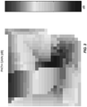
- Figure 3 shows an example where path gain is computed for the points in the floorplan.
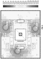
- Figure 4 shows a more detailed visualization of the floorplan of Figure 1 .
- MIMO Multiple-Input and Multiple-Input and Multiple-Output
- a method includes obtaining the antenna deployment including antennas and corresponding locations for the antennas, a cell assignment for the antennas such that each antenna is assigned to one cell out of one or more cells, and a resource assignment for the antennas such that each antenna is assigned to one radio resource out of one or more radio resources. Based on the antenna deployment, the cell assignment, and the resource assignment, the method determines at least one performance metric of the antenna deployment. This may provide a lightweight and efficient method to design a distributed antenna deployment. The resulting network may be optimized in terms the total area where a high rank is achieved.
- Figure 5 illustrates a method for determining a performance metric for an antenna deployment.
- an antenna deployment including antennas and corresponding locations for the antennas, a cell assignment for the antennas such that each antenna is assigned to one cell out of one or more cells, and a resource assignment for the antennas such that each antenna is assigned to one radio resource out of one or more radio resources are obtained (step 500).
- the method determines at least one performance metric of the antenna deployment (step 502).
- the method takes an antenna deployment as an input.
- This input can be user-defined or automatically generated by an optimization algorithm.
- the x and y coordinates of the antennas and the path loss of the deployment area are used to compute the following outputs: assignment of antennas to radio resources (also referred to as data streams) and cells.
- radio resources also referred to as data streams
- each cell transmits N data streams.
- Antennas can only transmit a single, unique data stream, as such data streams must be assigned to antennas optimally such that users see the maximum benefit of a MIMO network.
- MIMO network performance is maximized when a good signal is received from each unique data stream.
- the Ericsson Indoor Planner (EIP) tool is used to generate an antenna deployment.
- the solution is inserted after the deployment step and after radio resources are assigned to antennas.
- Figure 6 realizes the integration of this solution with an existing deployment tool.
- an existing antenna deployment such as a Distributed Antenna System (DAS) head deployment
- DAS Distributed Antenna System
- each head is assigned first to a cell and then to a radio; via the processes depicted in Figure 6 .
- antennas are assigned to cells (step 602).
- radio resources are assigned to the antennas (step 604).
- the performance can then be calculated (step 606) and the method can return to some remaining system (608). Additional details regarding the calculation of performance are provided in Figures 7 through 10 .
- Figure 7 illustrates an example implementation of step 606. In some embodiments, all three of these steps are performed. In other embodiments, only a subset of these steps is performed.
- the Rank of the antenna deployment is calculated (step 700).
- a cumulative signal is calculated (step 702).
- the bitrate for the antenna deployment can be calculated (step 704).
- Figures 8 , 9 , and 10 outline exemplary methods used to calculate Rank, cumulative signal, and bitrate. In the following figures, once a radio resource has been assigned to an antenna, that antenna emits a data stream unique to that radio resource.
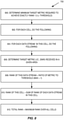
- Figure 8 illustrates an exemplary implementation of step 700.
- the first step is to choose an appropriate metric (or combination) that has a strong relationship to the Rank.
- find the threshold required to achieve at least a Rank of 1.0 step 800.
- empirical data was collected, and a threshold was extracted.
- the following steps are then taken to calculate Rank (using signal power as the metric):
- the total Rank for this antenna deployment is the maximum rank over all of the cells (step 812).
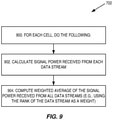
- Figure 9 illustrates an exemplary implementation of step 702.
- the per-data stream Rank can be used to find an equivalent cumulative signal. To do this, for each cell (step 900), the signal received from antennas emitting the same data stream is summed (step 902). The summed signal of each data stream is then multiplied by a weight derived from its Rank and summed with the weighted signals of the other data streams in this cell (step 904). Alternatively, the resulting cell signal can be found by summing the signals of all data streams of the same cell, instead of using the weighted average approach.
- Figure 10 illustrates an exemplary implementation of step 704.
- the cumulative signal In order to calculate the bitrate, the cumulative signal must be converted to a SINR (step 1000) and this SINR, in turn, is converted to a bitrate. If the maximum achievable Rank is N, then a unique SINR to bitrate conversion is done for each of the following 1x1, 2x2, ..., NxN antenna configurations (step 1002).
- the achievable bitrate is calculated as the weighted average of the MxM and NxN bitrates (where M and N are the closest integers to the Rank achieved in this area) (step 1006).
- the weight is determined by how close the achieved Rank is to M and N.
- FIG 11 is a schematic block diagram of a computation node 1100 according to some embodiments of the present disclosure.
- the computation node 1100 includes a control system 1102 that includes one or more processors 1104 (e.g., Central Processing Units (CPUs), Application Specific Integrated Circuits (ASICs), Field Programmable Gate Arrays (FPGAs), and/or the like), memory 1106, and a network interface 1108.
- the one or more processors 1104 are also referred to herein as processing circuitry.
- the one or more processors 1104 operate to provide one or more functions of a computation node 1100 as described herein.
- the function(s) are implemented in software that is stored, e.g., in the memory 1106 and executed by the one or more processors 1104.
- Figure 12 is a schematic block diagram that illustrates a virtualized embodiment of the computation node 1100 according to some embodiments of the present disclosure. This discussion is equally applicable to other types of network nodes or computation nodes. Further, other types of network nodes and computation nodes may have similar virtualized architectures.
- a "virtualized" computation node is an implementation of the computation node 1100 in which at least a portion of the functionality of the computation node 1100 is implemented as a virtual component(s) (e.g., via a virtual machine(s) executing on a physical processing node(s) in a network(s)).
- the computation node 1100 includes the control system 1102 that includes the one or more processors 1104 (e.g., CPUs, ASICs, FPGAs, and/or the like), the memory 1106, and the network interface.
- the control system 1102 is connected to one or more processing nodes 1200 coupled to or included as part of a network(s) 1202 via the network interface 1108.
- Each processing node 1200 includes one or more processors 1204 (e.g., CPUs, ASICs, FPGAs, and/or the like), memory 1206, and a network interface 1208.
- functions 1210 of the computation node 1100 described herein are implemented at the one or more processing nodes 1200 or distributed across the control system 1102 and the one or more processing nodes 1200 in any desired manner.
- some or all of the functions 1210 of the computation node 1100 described herein are implemented as virtual components executed by one or more virtual machines implemented in a virtual environment(s) hosted by the processing node(s) 1200.
- additional signaling or communication between the processing node(s) 1200 and the control system 1102 is used in order to carry out at least some of the desired functions 1210.
- a computer program including instructions which, when executed by at least one processor, causes the at least one processor to carry out the functionality of computation node 1100 or a node (e.g., a processing node 1200) implementing one or more of the functions 1210 of the computation node 1100 in a virtual environment according to any of the embodiments described herein is provided.
- a carrier comprising the aforementioned computer program product is provided. The carrier is one of an electronic signal, an optical signal, a radio signal, or a computer readable storage medium (e.g., a non-transitory computer readable medium such as memory).
- FIG 13 is a schematic block diagram of the computation node 1100 according to some other embodiments of the present disclosure.
- the computation node 1100 includes one or more modules 1300, each of which is implemented in software.
- the module(s) 1300 provide the functionality of the computation node 1100 described herein. This discussion is equally applicable to the processing node 1200 of Figure 12 where the modules 1300 may be implemented at one of the processing nodes 1200 or distributed across multiple processing nodes 1200 and/or distributed across the processing node(s) 1200 and the control system 1102.
- any appropriate steps, methods, features, functions, or benefits disclosed herein may be performed through one or more functional units or modules of one or more virtual apparatuses.
- Each virtual apparatus may comprise a number of these functional units.
- These functional units may be implemented via processing circuitry, which may include one or more microprocessor or microcontrollers, as well as other digital hardware, which may include Digital Signal Processor (DSPs), special-purpose digital logic, and the like.
- the processing circuitry may be configured to execute program code stored in memory, which may include one or several types of memory such as Read Only Memory (ROM), Random Access Memory (RAM), cache memory, flash memory devices, optical storage devices, etc.
- Program code stored in memory includes program instructions for executing one or more telecommunications and/or data communications protocols as well as instructions for carrying out one or more of the techniques described herein.
- the processing circuitry may be used to cause the respective functional unit to perform corresponding functions according one or more embodiments of the present disclosure.
Description
- This application claims the benefit of provisional patent application serial number
62/673,443, filed May 18, 2018 - The disclosure relates to designing wireless communications, and in particular, to designing Multiple-Input and Multiple-Output (MIMO) networks.
- Planning products can be used to design network deployments. Some enable the automation of some of the planning process, significantly reducing planning times. Some planning products enable users to import a floor plan and use it to create a plan for the locations of network products and associated cabling. Users can modify several floor attributes including wall materials and structures to produce more accurate planning results. Users can also modify node locations to suit their own situation. Output from the tool sometimes includes a coverage report, a Bill of Materials to help in ordering, and a solution report listing the required hardware and cabling on each floor of the building.
- There currently exist solutions for simulating the performance of Multiple-Input and Multiple-Output (MIMO) networks where antennas are placed in very close proximity (approximately a few centimeters apart).
- Existing solutions cannot simulate the performance of a MIMO network where antennas are distributed (i.e. placed far apart from each other). As such, additional ways of determining a performance metric for an antenna deployment are needed.
- Document
US 2013/0183961 A1 discloses a method and system for communication network design. The method includes generating, by a computer processor, a plurality of receiver points and generating a target received signal strength for each receiver point of the plurality of receiver points. The method further includes determining a predicted number of antennas based on a size of the communications network and a coverage area of an antenna, and determining a location for each antenna of the predicted number of antennas. The method still further includes generating an estimated received signal strength for each receiver point of the plurality of receiver points, based upon the predicted number of antennas and upon the location of each antenna of the predicted number of antennas. The method also includes comparing the estimated received signal strength for each receiver point with the target received signal strength for the receiver point and generating a revised predicted number of antennas based upon at least one of the comparisons of target received signal strength and estimated received signal strength. - Document
CN 102 098 689 A discloses an automatic antenna distribution method and an automatic antenna distribution system for an indoor distributed wireless network. The method comprises the following steps of: 1, initializing the antenna distribution density and antenna distribution positions of the indoor distributed wireless network to be distributed; 2, simulating current distribution by using a preset propagation model; 3, judging whether a coverage simulation result meets the requirements of a preset coverage objective or not, performing a step 4 if the coverage simulation result does not meet the requirements of the preset coverage objective, and finishing the arrangement if the coverage simulation result meets the requirements of the preset coverage objective; 4, calculating a wireless signal field intensity attenuation gradient of the antenna distribution positions in divided directional lines according to the simulation result of the current distribution of antennae, and regulating the antenna distribution positions according to the wireless signal field intensity attenuation gradient; and 5, searching for coverage holes and overlapped coverage areas of the indoor distributed wireless network according to the simulation result, regulating the antenna distribution intensity according to the coverage holes and the overlapped coverage areas, and performing thestep 2. - Document
US 7 085 697 B1 discloses a computerized model providing a display of a physical environment in which a communications network is or will be installed. The communications network is comprised of several components, each of which are selected by the design engineer and which are represented in the display. Errors in the selection of certain selected components for the communications network are identified by their attributes or frequency characteristics as well as by their interconnection compatibility for a particular design. The effects of changes in frequency on component performance are modeled and the results are displayed to the design engineer. A bill of materials is automatically checked for faults, generated for the design system and provided to the design engineer. For ease of design, the design engineer can cluster several different preferred components into component kits, and then select these component kits for use In the design or deployment process. - A method and a computation node for determining a performance metric for an antenna deployment are provided according to the independent claims. Preferred embodiments are recited in the dependent claims.
- The accompanying drawing figures incorporated in and forming a part of this specification illustrate several aspects of the disclosure, and together with the description serve to explain the principles of the disclosure.
-
Figure 1 illustrates a sample floorplan, according to some embodiments of the present disclosure; -
Figure 2 illustrates an example floorplan that has been segmented into discrete locations, according to some embodiments of the present disclosure; -
Figure 3 illustrates an example where path gain is computed for the points in the floorplan, according to some embodiments of the present disclosure; -
Figure 4 illustrates a more detailed visualization of the floorplan ofFigure 1 in which there are three antennas at specific locations, according to some embodiments of the present disclosure; -
Figure 5 illustrates a method for determining an assignment of radio resources to antennas, according to some embodiments of the present disclosure; -
Figure 6 illustrates an integration of some current embodiments with an existing deployment tool, according to some embodiments of the present disclosure; -
Figure 7 illustrates a method of operation, according to some embodiments of the present disclosure; -
Figure 8 illustrates a method of operation, according to some embodiments of the present disclosure; -
Figure 9 illustrates a method of operation, according to some embodiments of the present disclosure; -
Figure 10 illustrates a method of operation, according to some embodiments of the present disclosure; -
Figure 11 is a schematic block diagram of a computation node, according to some embodiments of the present disclosure; -
Figure 12 is a schematic block diagram that illustrates a virtualized embodiment of the computation node according to some embodiments of the present disclosure; and -
Figure 13 is a schematic block diagram of the computation node according to some other embodiments of the present disclosure. - The embodiments set forth below represent information to enable those skilled in the art to practice the embodiments and illustrate the best mode of practicing the embodiments. Upon reading the following description in light of the accompanying drawing figures, those skilled in the art will understand the concepts of the disclosure and will recognize applications of these concepts not particularly addressed herein. It should be understood that these concepts and applications fall within the scope of the disclosure.
- As discussed in more detail below, many of the embodiments discussed herein relate to planning and implementing an indoor network deployment. However, these embodiments are not limited thereto and could be applicable in many contexts. In some embodiments, a floorplan is used such as is shown in
Figure 1 . This may include outside walls, inside walls and various other structures. Additionally, the materials of these structures may be defined and/or the radio propagation characteristics may be known or derived. -
Figure 2 illustrates another example floorplan that has been segmented into discrete locations. In this example, many individual points inside the floorplan are assigned x, y coordinates. If an antenna is placed in this floorplan, various radio characteristics can be calculated for these x, y coordinates. For instance,Figure 3 shows an example where path gain is computed for the points in the floorplan. -
Figure 4 shows a more detailed visualization of the floorplan ofFigure 1 . In this figure, there are three antennas at specific locations and the values of the signal are shown using different colors. - There currently exist solutions for designing Multiple-Input and Multiple-Input and Multiple-Output (MIMO) networks where antennas are placed in very close proximity (approximately a few centimeters apart). However, existing solutions are not capable of simulating the performance of a MIMO network where antennas are distributed (i.e. placed far apart from each other).
- Systems and methods for determining a performance metric for an antenna deployment are provided. In some embodiments, a method includes obtaining the antenna deployment including antennas and corresponding locations for the antennas, a cell assignment for the antennas such that each antenna is assigned to one cell out of one or more cells, and a resource assignment for the antennas such that each antenna is assigned to one radio resource out of one or more radio resources. Based on the antenna deployment, the cell assignment, and the resource assignment, the method determines at least one performance metric of the antenna deployment. This may provide a lightweight and efficient method to design a distributed antenna deployment. The resulting network may be optimized in terms the total area where a high rank is achieved.
-
Figure 5 illustrates a method for determining a performance metric for an antenna deployment. First, an antenna deployment including antennas and corresponding locations for the antennas, a cell assignment for the antennas such that each antenna is assigned to one cell out of one or more cells, and a resource assignment for the antennas such that each antenna is assigned to one radio resource out of one or more radio resources are obtained (step 500). Then, based on the antenna deployment, the cell assignment, and the resource assignment, the method determines at least one performance metric of the antenna deployment (step 502). - In some embodiments, the method takes an antenna deployment as an input. This input can be user-defined or automatically generated by an optimization algorithm. The x and y coordinates of the antennas and the path loss of the deployment area are used to compute the following outputs: assignment of antennas to radio resources (also referred to as data streams) and cells. In a NxN MIMO network each cell transmits N data streams. Antennas can only transmit a single, unique data stream, as such data streams must be assigned to antennas optimally such that users see the maximum benefit of a MIMO network. MIMO network performance is maximized when a good signal is received from each unique data stream.
- To evaluate the solution that is proposed, the Ericsson Indoor Planner (EIP) tool is used to generate an antenna deployment. The solution is inserted after the deployment step and after radio resources are assigned to antennas.
Figure 6 realizes the integration of this solution with an existing deployment tool. Given an existing antenna deployment such as a Distributed Antenna System (DAS) head deployment, each head is assigned first to a cell and then to a radio; via the processes depicted inFigure 6 . Starting with an antenna deployment (step 600), antennas are assigned to cells (step 602). Then radio resources are assigned to the antennas (step 604). The performance can then be calculated (step 606) and the method can return to some remaining system (608). Additional details regarding the calculation of performance are provided inFigures 7 through 10 . -
Figure 7 illustrates an example implementation ofstep 606. In some embodiments, all three of these steps are performed. In other embodiments, only a subset of these steps is performed. First, the Rank of the antenna deployment is calculated (step 700). Then, a cumulative signal is calculated (step 702). In some embodiments, based on the results of the previous two steps, the bitrate for the antenna deployment can be calculated (step 704). Given an existing antenna deployment and the assignment of radio resources to antennas,Figures 8 ,9 , and10 outline exemplary methods used to calculate Rank, cumulative signal, and bitrate. In the following figures, once a radio resource has been assigned to an antenna, that antenna emits a data stream unique to that radio resource. -
Figure 8 illustrates an exemplary implementation ofstep 700. Given an existing antenna deployment and the assignment of radio resources to antennas, the Rank achieved in various positions can be calculated. The first step is to choose an appropriate metric (or combination) that has a strong relationship to the Rank. Using this metric, find the threshold required to achieve at least a Rank of 1.0 (step 800). In one implementation of this solution in the Ericsson Indoor Planner tool, empirical data was collected, and a threshold was extracted. The following steps are then taken to calculate Rank (using signal power as the metric): - 1. For each data stream in each cell (
steps 802 and 804), determine a target metric received in a given area by, for example, summing the signal power from all antennas received in a given area (806). - 2. Calculate the ratio of this summed signal, over the noise floor, to the threshold (required to achieve Rank 1.0 as determined earlier) (step 808). The Rank of this data stream (at a point) is the minimum of the calculated ratio or 1. A value of 1 implies that the signal power of this data stream, received by a user, at this point is enough to achieve a Rank of 1.0.
- 3. The Rank of each cell is then defined as the sum of the Rank of each data stream within the cell (step 810).
- The total Rank for this antenna deployment is the maximum rank over all of the cells (step 812).
-
Figure 9 illustrates an exemplary implementation ofstep 702. For a deployment with antennas assigned to cells and radio resources, the per-data stream Rank can be used to find an equivalent cumulative signal. To do this, for each cell (step 900), the signal received from antennas emitting the same data stream is summed (step 902). The summed signal of each data stream is then multiplied by a weight derived from its Rank and summed with the weighted signals of the other data streams in this cell (step 904). Alternatively, the resulting cell signal can be found by summing the signals of all data streams of the same cell, instead of using the weighted average approach. -
Figure 10 illustrates an exemplary implementation ofstep 704. In order to calculate the bitrate, the cumulative signal must be converted to a SINR (step 1000) and this SINR, in turn, is converted to a bitrate. If the maximum achievable Rank is N, then a unique SINR to bitrate conversion is done for each of the following 1x1, 2x2, ..., NxN antenna configurations (step 1002). - M = floor(Rank) and N = ceiling(Rank) (step 1004). For a given area, the achievable bitrate is calculated as the weighted average of the MxM and NxN bitrates (where M and N are the closest integers to the Rank achieved in this area) (step 1006). The weight is determined by how close the achieved Rank is to M and N.
- For illustrative purposes, pseudocode for performing some of the methods discussed herein is provided. This only represents an example implementation and the current disclosure is not limited thereto.
[totalRank, cumulativeSignal, bitrate] = calculatePerformance (deployment, xyArea,
 pathGain, interferenceAncNoise, TxPower, rateMap, nStreams, thresholdForRank1) {
 /*
 deployment is either a user input OR is auto-generated (not part of IvD)
 pre-calculated variables:
 * xyArea
 * x & y coordinates for every point in the Area of Interest (Aol)
 * pathGain
 * path gain from point A to point B, where A and B are both points in the deployment
 area
 * interferenceAncNoise
 * random noise and interference from other sources received at each point in the Aol
 * rate Map
 * a table that correlates SNR to throughput, for a given MIMO configuration
 * these can be found by collecting data in a lab or using simulation software
 * ratemaps are required for all MxM MIMO configurations, where M <= N
 * e.g. 1×1, 2x2, 3x3, ..., NxN
 constants: (can be user-defined)
 * TxPower
 * transmitting power of one antenna
 * nStreams
 * value of N if objective is NxN MIMO
 * thresholdForRank1
 * the 'metric' value that results in exactly Rank 1.0. A value higher than this threshold
 will yield no performance improvements. While a value even slightly less than this
 threshold will result in a loss of performance.
 * e.g., transmitted signal power can be used as the 'metric' and the signal power that
 results in Rank 1.0 will then be used as the 'thresholdForRank1'
 */
 rank = calculateRankPerStream (deployment, xyArea, pathGain, interferenceAncNoise,
 TxPower, nStreams, thresholdForRank1)
 totalRank = calculateRank (deployment, xyArea, rank, nStreams)
 cumulativeSignal = calculateCumulativeSignal (deployment, xyArea, rank, pathGain,
 TxPower, nStreams)
 /* using cumulativeSignal, calculate SNR (this is not novel to the IvD - there is no
 pseudo code for this function) */
 SNR = calculateSNR (cumulativeSignal)
 }bitrate = calculateBitrate (deployment, xyArea, totalRank, rateMap, SNR, nStreams)
 [ bitrate ] = calculateBitrate ( xyArea, totalRank, rateMap, SNR ) {
 /*
 xyArea: x & y coordinates for every point in the Area of Interest (Aol)
 xyArea[index] = (x[index], y[index])
 totalRank: the ratio of a streams signal strength to the signal level that results in Rank
 1.0, on a per stream, per cell, per point basis
 totalRank[(x, y)] = totalRank of 'stream' transmitted by 'cell' seen at point 'xy' in the Aol
 rateMap: a user-defined (retrieved from simulations or hardware testing) table that
 correlates SNR to throughput
 rateMap[N, SNR] = the maximum number of bits that can be downloaded at a given
 SNR if there are N transmitting streams in the network
 SNR: the SNR at a point in the Aol
 bitrate: the maximum achievable bitrate at a point in the Aol
 */
 for (xy in xyArea) {
 rankBelow = floor(totalRank)
 rankAbove = ceil(totalRank)
 rankBelowMultiplier = totalRank[xy] - rankBelow
 rankAboveMultiplier = rankAbove - totalRank[xy]
 bitrate[xy] = (rateMap[rankBelow, SNR[xy]] * rankBelowMultiplier) +
 (rateMap[rankAbove, SNR[xy]] * rankBelowMultiplier)
 }
 }
 [ cumulativeSignal ] = calculateCumulativeSignal ( deployment, xyArea, rank, pathGain,
 TxPower, nStreams ) {
 /*
 deployment: x and y coordinates AND cell IDs of all the antennas deployed in
 deployment area
 xyArea: x & y coordinates for every point in the Area of Interest (Aol)
 xyArea[index] = (x[index], y[index])
 rank: the ratio of a streams signal strength to the signal level that results in Rank 1.0, on
 a per stream, per cell, per point basis
 rank[cell, stream, (x, y)] = rank of 'stream' transmitted by 'cell' seen at point 'xy' in the
 Aol
 pathGain: path gain from point A to point B, where A and B are both points in the
 deployment area
 pathGain[index_A, index_B] = path gain from point A to point B
 TxPower: the transmit power of one antenna
 nStreams: the number of unique data streams that radio in this network produce
 e.g. if goal is 4x4 MIMO, nStreams = 4
 cumulativeSignal: the total signal received at a point in the Aol (signals are weighted
 based on the rank of each stream signal received)
* the terms 'radios', 'radio resources', 'data streams', & 'streams' are used
 interchangeably
 */
 /* signal from point A to point B, where A is a transmitting point and B is a receiving
 point, in the deployment area */
 signal = TxPower * pathGain
 // for each cell in the deployment...
 for (cell = 1; cell <= max(deployment.cellID)) {
 // ...find which antennas are in this cell
 cellMask = deployment.cellID == cell
 // ...for each stream transmitted in this cell...
 for (stream = 1; stream < nStreams) {
 // ...find which antennas are transmitting this stream
 cellStreamMask = cellMask & deployment.stream == stream
 // ...for each point in the Aol...
 for (xy in xyArea) {
 /* ...calculate the weighted summed signal strength of all streams received in this
 location, transmitted by antennas in this cell */
 streamSignal = sum(signal[(deployment[cellStreamMask].x,
 deployment[cellStreamMask].y), xy])
 weightedStreamSignal[cell, xy] += rank[cell, stream, xy] * streamSignal
 //Alternatively: aggregatedCellSignal[cell,xy] += streamSignal }
 }
 /* ...find which cell transmits the strongest signal to each point and save that signal
 level to the cumulative signal */
 cumulativeSignal = max(cumulativeSignal, weightedStreamSignal[cell] / nStreams)
 // Alternatively: cumulativeSignal = max(cumulativeSignal, aggregatedCellSignal[cell])
 [ total Rank ] = calculateRank ( deployment, xyArea, rank, nStreams ) {
 /*
 deployment: x and y coordinates AND cell IDs of all the antennas deployed in
 deployment area
 xyArea: x & y coordinates for every point in the Area of Interest (Aol)
 xyArea[index] = (x[index], y[index])
 rank: the ratio of a streams signal strength to the signal level that results in Rank 1.0, on
 a per stream, per cell, per point basis
 rank[cell, stream, (x, y)] = rank of 'stream' transmitted by 'cell' seen at point 'xy' in the
 Aol
 nStreams: the number of unique data streams that radio in this network produce
 e.g. if goal is 4x4 MIMO, nStreams = 4
 total Rank: same as rank but on a per point basis
 totalRank[(x, y)] = rank of all streams transmitted by the strongest cell seen at point 'xy'
 in the Aol
* the terms 'radios', 'radio resources', 'data streams', & 'streams' are used
 interchangeably
 */
 total RankPerCell = zeros(size(xyArea))
 total Rank = zeros(size(xyArea))
 // for each cell in the deployment...
 for (cell = 1; cell <= max(deployment.cellID)) {
 // ...for each stream transmitted in this cell...
 for (stream = 1; stream < nStreams) {
 // ...for each point in the Aol...
 for (xy in xyArea) {
 // ...the total rank in the area served by this cell, is the sum of the per stream rank
 totalRankPerCell[cell, xy] += rank[cell, stream, xy]
 } }
 // ...the total rank at each point, is the maximum rank achieved by any cell
 totalRank = max(totalRankPerCell, totalRank)
 } }
 [ rank ] = calculateRankPerStream ( deployment, xyArea, pathGain,
 interferenceAncNoise, TxPower, nStreams, thresholdForRank1 ) {
 /*
 deployment: x and y coordinates AND cell IDs of all the antennas deployed in
 deployment area
 xyArea: x & y coordinates for every point in the Area of Interest (Aol)
 xyArea[index] = (x[index], y[index])
 pathGain: path gain from point A to point B, where A and B are both points in the
 deployment area
 pathGain[index_A, index_B] = path gain from point A to point B
 interferenceAncNoise: random noise and interference from other sources received at
 each point in the Aol
 interferenceAncNoise[index] = noise and interference at xyArea[index]
 TxPower: the transmit power of one antenna
 nStreams: the number of unique data streams that radio in this network produce
 e.g., if goal is 4x4 MIMO, nStreams = 4
 thresholdForRank1: signal level that results in Rank 1.0
 rank: the ratio of a streams signal strength to the signal level that results in Rank 1.0, on
 a per stream, per cell, per point basis
 rank[cell, stream, (x, y)] = rank of 'stream' transmitted by 'cell' seen at point 'xy' in the
 Aol
* the terms 'radios', 'radio resources', 'data streams', & 'streams' are used
 interchangeably
 */
 /* signal from point A to point B, where A is a transmitting point and B is a receiving
 point, in the deployment area */
 signal = TxPower * pathGain - interferenceAncNoise
 // for each cell in the deployment...
 for (cell = 1; cell <= max(deployment.cellID)) {
 // ...find which antennas are in this cell
 cellMask = deployment.cellID == cell
 // ...for each stream transmitted in this cell...
 for (stream = 1; stream < nStreams) {
 // ...find which antennas are transmitting this stream
 cellStreamMask = cellMask & deployment.stream == stream
 // ...for each point in the Aol...
 for (xy in xyArea) {
 /* ...calculate the summed signal strength of this stream received in this location,
 transmitted by antennas in this cell */
 cellStreamSignal[cell, stream, xy] = sum(signal[(deployment[cellStreamMask].x,
 deployment[cellStreamMask].y), xy])
 }
 // the rank of this stream (at each point) is the minimum of the calculated ratio or 1
 signalRatioToThreshold = cellStreamSignal[cell, stream] / thresholdForRank1
 rank[cell, stream] = min(1, signalRatioToThreshold)
 } } }
| AoI | Area of Interest | |
| ASIC | Application Specific Integrated Circuit | |
| CPU | Central Processing Unit | |
| DAS | Distributed Antenna System | |
| DSP | Digital Signal Processor | |
| EIP | Ericsson Indoor Planner | |
| FPGA | Field Programmable Gate Array | |
| MIMO | Multiple Input Multiple Output | |
| RAM | Random Access Memory | |
| ROM | Read Only Memory | |
| SINR | Signal-to-Interference-plus-Noise Ratio | |
| ▪ | SNR | Signal-to-Noise Ratio |
Claims (15)
- A method performed by a computation node (1100) for determining a performance metric for an antenna deployment, the method comprising:obtaining (500, 600, 602, 604) the antenna deployment comprising a plurality of antennas and corresponding locations for the plurality of antennas, a cell assignment for the plurality of antennas such that each antenna is assigned to one cell out of one or more cells, and a resource assignment for the plurality of antennas such that each antenna is assigned to one radio resource out of one or more radio resources; andbased on the antenna deployment, the cell assignment, and the resource assignment, determining (700) a rank of the antenna deployment, where determining the rank of the antenna deployment comprises:determining (800) a minimum target metric required to achieve exactly a rank of one;for each cell (802) and for each data stream in this cell (804):determining (806) a target metric received in a given area;determining (808) that a rank of this data stream is a ratio of the target metric to the minimum target metric; anddetermining (810) that a rank of this cell is a sum of ranks of each data stream in this cell; anddetermining (812) that the rank of the antenna deployment is a maximum rank of a rank of each of the cells.
- The method of claim 1, wherein at least one of obtaining the antenna deployment, obtaining the cell assignment, and obtaining the resource assignment comprises receiving the antenna deployment, the cell assignment, and the resource assignment, respectively; and/or
wherein at least one of obtaining the antenna deployment, obtaining the cell assignment, and obtaining the resource assignment comprises generating the antenna deployment, the cell assignment, and the resource assignment, respectively - The method of any one of claims 1 to 2, wherein the target metric is chosen from the group consisting of a Signal-to-Noise-Ratio, SNR, and a Signal-to-Interference-plus-Noise Ratio, SINR; and/or
wherein the rank of this data stream is a maximum of one. - The method of any of claims 1 to 3, further comprising determining (702) a cumulative signal of the antenna deployment, whereini) determining the cumulative signal of the antenna deployment comprises:for each cell (900) determining (902) a signal power received from each data stream; anddetermining (904) that the cumulative signal of the antenna deployment is a weighted average of the signal power received from each data stream; and, optionallywherein the rank of each data stream is used as a weight for that data stream in the weighted average; orii) the cumulative signal of the antenna deployment is determined by summing the signals of all the data streams of the same cell.
- The method of claim 4, further comprising: determining (704) an achievable bitrate of the antenna deployment.
- The method of claim 5, wherein determining the achievable bitrate of the antenna deployment comprises:converting (1000) the cumulative signal of the antenna deployment to at least one of the SNR and the SINR;mapping (1002) the at least one of the SNR and the SINR to a bitrate for each N × N Multiple-Input and Multiple-Output, MIMO, combination;determining (1004) a ceiling of the rank of the antenna deployment and a floor of the rank of the antenna deployment; anddetermining (1006) the achievable bitrate of the antenna deployment as the weighted average of the bitrate mapped to by the ceiling of the rank and the bitrate mapped to by the floor of the rank.
- The method of claim 6, wherein the ceiling of the rank and the floor of the rank for the bitrate mapped to the ceiling of the rank and the floor of the rank is used as a weight for that bitrate in the weighted average.
- A computation node (1100) for determining an assignment of radio resources to antennas, the computation node comprising:
processing circuitry (1104, 1106, 1204, 1206) configured to:obtain an antenna deployment comprising a plurality of antennas and corresponding locations for the plurality of antennas, a cell assignment for the plurality of antennas such that each antenna is assigned to one cell out of one or more cells, and a resource assignment for the plurality of antennas such that each antenna is assigned to one radio resource out of one or more radio resources; andbased on the antenna deployment, the cell assignment, and the resource assignment, determine a rank of the antenna deployment, where determining the rank of the antenna deployment comprises the processing circuitry further being configured to:determine a minimum target metric required to achieve exactly a rank of one;for each cell (802) and for each data stream in this cell (804):determine a target metric received in a given area;determine that a rank of this data stream is a ratio of the target metric to the minimum target metric; anddetermine that a rank of this cell is a sum of ranks of each data stream in this cell; anddetermine that the rank of the antenna deployment is a maximum rank of a rank of each of the cells. - The computation node (1100) of claim 8, wherein at least one of obtaining the antenna deployment, obtaining the cell assignment, and obtaining the resource assignment comprises the processing circuitry further configured to receive the antenna deployment, the cell assignment, and the resource assignment, respectively; and/or
wherein at least one of obtaining the antenna deployment, obtaining the cell assignment, and obtaining the resource assignment comprises the processing circuitry further configured to generate the antenna deployment, the cell assignment, and the resource assignment, respectively. - The computation node (1100) of any of claims 8 to 9, wherein the target metric is chosen from the group consisting of a Signal-to-Noise-Ratio, SNR, and a Signal-to-Interference plus-Noise Ratio, SINR.
- The computation node (1100) of any of claims 8 to 10, wherein the rank of this data stream is a maximum of one.
- The computation node (1100) of any of claims 8 to 11, wherein the processing circuitry is further configured to determine a cumulative signal of the antenna deployment, whereini) determining the cumulative signal of the antenna deployment comprises the processing circuitry further being configured to:for each cell (900) determine a signal power received from each data stream; anddetermine that the cumulative signal of the antenna deployment is a weighted average of the signal power received from each data stream; and, optionally,wherein the rank of each data stream is used as a weight for that data stream in the weighted average; orii) the cumulative signal of the antenna deployment is determined by summing the signals of all the data streams of the same cell.
- The computation node (1100) of claim 12, wherein the processing circuitry is further configured to determine an achievable bitrate of the antenna deployment.
- The computation node (1100) of claim 13, wherein determining the achievable bitrate of the antenna deployment comprises the processing circuitry further configured to:convert the cumulative signal of the antenna deployment to at least one of the SNR and the SINR;map the at least one of the SNR and the SINR to a bitrate for each N × N Multiple-Input and Multiple-Output, MIMO, combination;determine a ceiling of the rank of the antenna deployment and a floor of the rank of the antenna deployment; anddetermine the achievable bitrate of the antenna deployment as the weighted average of the bitrate mapped to by the ceiling of the rank and the bitrate mapped to by the floor of the rank.
- The computation node (1100) of claim 14, wherein the ceiling of the rank and the floor of the rank for the bitrate mapped to the ceiling of the rank and the floor of the rank is used as a weight for that bitrate in the weighted average.
Applications Claiming Priority (2)
| Application Number | Priority Date | Filing Date | Title |
|---|---|---|---|
| US201862673443P | 2018-05-18 | 2018-05-18 | |
| PCT/IB2019/053395 WO2019220244A1 (en) | 2018-05-18 | 2019-04-24 | Performance simulation of a distributed mimo antenna system |
Publications (2)
| Publication Number | Publication Date |
|---|---|
| EP3794861A1 EP3794861A1 (en) | 2021-03-24 |
| EP3794861B1 true EP3794861B1 (en) | 2022-02-23 |
Family
ID=66752144
Family Applications (1)
| Application Number | Title | Priority Date | Filing Date |
|---|---|---|---|
| EP19728519.0A Active EP3794861B1 (en) | 2018-05-18 | 2019-04-24 | Performance simulation of a distributed mimo antenna system |
Country Status (4)
| Country | Link |
|---|---|
| US (1) | US11356858B2 (en) |
| EP (1) | EP3794861B1 (en) |
| TW (1) | TWI761676B (en) |
| WO (1) | WO2019220244A1 (en) |
Families Citing this family (1)
| Publication number | Priority date | Publication date | Assignee | Title |
|---|---|---|---|---|
| WO2019220243A1 (en) | 2018-05-18 | 2019-11-21 | Telefonaktiebolaget Lm Ericsson (Publ) | Systems and methods for designing a distributed mimo network |
Family Cites Families (9)
| Publication number | Priority date | Publication date | Assignee | Title |
|---|---|---|---|---|
| US7085697B1 (en) * | 2000-08-04 | 2006-08-01 | Motorola, Inc. | Method and system for designing or deploying a communications network which considers component attributes |
| US8059608B2 (en) | 2005-06-14 | 2011-11-15 | Qualcomm Incorporated | Transmit spatial diversity for cellular single frequency networks |
| US20100067435A1 (en) * | 2008-09-18 | 2010-03-18 | Krishna Balachandran | Architecture to support network-wide multiple-in-multiple-out wireless communication over an uplink |
| US8761834B2 (en) * | 2008-12-31 | 2014-06-24 | Motorola Mobility Llc | Method and apparatus for antenna selection and power control in a multiple input multiple output wireless communication system |
| CN102098689B (en) * | 2009-12-14 | 2013-03-27 | 中国联合网络通信集团有限公司 | Antenna automatic-distribution method and device for indoor distributed wireless network |
| KR101605326B1 (en) * | 2010-02-26 | 2016-04-01 | 엘지전자 주식회사 | A method for transmitting a signal and a base station thereof, and a method for receiving a signal and a user equipment thereof |
| AU2011274307B2 (en) | 2010-06-29 | 2016-07-14 | Commonwealth Scientific And Industrial Research Organisation | Dynamic network configuration |
| EP2617224A4 (en) * | 2010-09-17 | 2017-04-12 | Consistel Pte Ltd | Automatic network design |
| WO2019220243A1 (en) | 2018-05-18 | 2019-11-21 | Telefonaktiebolaget Lm Ericsson (Publ) | Systems and methods for designing a distributed mimo network |
-
2019
- 2019-04-24 WO PCT/IB2019/053395 patent/WO2019220244A1/en active Application Filing
- 2019-04-24 US US17/056,666 patent/US11356858B2/en active Active
- 2019-04-24 EP EP19728519.0A patent/EP3794861B1/en active Active
- 2019-05-17 TW TW108117019A patent/TWI761676B/en not_active IP Right Cessation
Also Published As
| Publication number | Publication date |
|---|---|
| US20210211891A1 (en) | 2021-07-08 |
| WO2019220244A1 (en) | 2019-11-21 |
| US11356858B2 (en) | 2022-06-07 |
| EP3794861A1 (en) | 2021-03-24 |
| TW202005314A (en) | 2020-01-16 |
| TWI761676B (en) | 2022-04-21 |
Similar Documents
| Publication | Publication Date | Title |
|---|---|---|
| CN110401964B (en) | Power control method based on deep learning for user-oriented center network | |
| CN110786046A (en) | Optimizing cellular networks using deep learning | |
| CN108260133A (en) | Method, network side equipment and the mobile terminal that a kind of wave beam measurement reports | |
| US20200366341A1 (en) | Software-defined massive multi-input multi-output (mimo) | |
| Bhardwaj et al. | Enhanced dynamic spectrum access in multiband cognitive radio networks via optimized resource allocation | |
| CN106972880B (en) | Low-complexity joint precoding method for transmitting end and relay based on SWIPT technology | |
| CN105744548B (en) | PCI optimization method and device | |
| EP3794861B1 (en) | Performance simulation of a distributed mimo antenna system | |
| US11770717B2 (en) | Systems and methods for designing a distributed MIMO network | |
| CN108631841A (en) | A kind of transmission wave beam determines method, transmitting terminal and receiving terminal | |
| CN102457360A (en) | Pre-coding processing method, pre-coding processing device and base station | |
| CN114554612A (en) | Multi-user scheduling method, base station and related device | |
| WO2023134650A1 (en) | Information interaction method and apparatus, and communication device | |
| CN105451293B (en) | Retransmission method in wireless network, the method and apparatus for determining forwarding strategy | |
| CN112929907B (en) | Method and device for determining antenna parameters | |
| CN105989407A (en) | Neural network based short wave median field intensity prediction system, method and device | |
| WO2023273679A1 (en) | Cooperating cell determining method and apparatus | |
| Wang et al. | Resource Allocation and EE-SE Tradeoff for H-CRAN with NOMA-Based D2D Communications | |
| JP6373483B2 (en) | Distributed antenna system with constraints on the average number of active backhaul links | |
| Lwin et al. | Enhancements of minimax access-point setup optimisation approach for IEEE 802.11 WLAN | |
| CN114144977B (en) | Beam forming method, device, wireless access network equipment and readable storage medium | |
| Li | Research on information capacity prediction of mobile sensing platform in internet of things based on collaborative congestion | |
| CN106341884A (en) | User location updating method and user location update device | |
| Jiang et al. | An Efficient Multi-Agent Optimization Approach for Coordinated Massive MIMO Beamforming | |
| WO2024084275A1 (en) | Processing a connection request by a cpu in a cell-free massive mimo network |
Legal Events
| Date | Code | Title | Description |
|---|---|---|---|
| STAA | Information on the status of an ep patent application or granted ep patent |
Free format text: STATUS: UNKNOWN |
|
| STAA | Information on the status of an ep patent application or granted ep patent |
Free format text: STATUS: THE INTERNATIONAL PUBLICATION HAS BEEN MADE |
|
| STAA | Information on the status of an ep patent application or granted ep patent |
Free format text: STATUS: THE INTERNATIONAL PUBLICATION HAS BEEN MADE |
|
| PUAI | Public reference made under article 153(3) epc to a published international application that has entered the european phase |
Free format text: ORIGINAL CODE: 0009012 |
|
| STAA | Information on the status of an ep patent application or granted ep patent |
Free format text: STATUS: REQUEST FOR EXAMINATION WAS MADE |
|
| 17P | Request for examination filed |
Effective date: 20201105 |
|
| AK | Designated contracting states |
Kind code of ref document: A1 Designated state(s): AL AT BE BG CH CY CZ DE DK EE ES FI FR GB GR HR HU IE IS IT LI LT LU LV MC MK MT NL NO PL PT RO RS SE SI SK SM TR |
|
| AX | Request for extension of the european patent |
Extension state: BA ME |
|
| DAV | Request for validation of the european patent (deleted) | ||
| DAX | Request for extension of the european patent (deleted) | ||
| GRAP | Despatch of communication of intention to grant a patent |
Free format text: ORIGINAL CODE: EPIDOSNIGR1 |
|
| STAA | Information on the status of an ep patent application or granted ep patent |
Free format text: STATUS: GRANT OF PATENT IS INTENDED |
|
| RIC1 | Information provided on ipc code assigned before grant |
Ipc: H04B 7/0413 20170101ALN20210914BHEP Ipc: H04W 16/18 20090101AFI20210914BHEP |
|
| INTG | Intention to grant announced |
Effective date: 20210930 |
|
| GRAS | Grant fee paid |
Free format text: ORIGINAL CODE: EPIDOSNIGR3 |
|
| GRAA | (expected) grant |
Free format text: ORIGINAL CODE: 0009210 |
|
| STAA | Information on the status of an ep patent application or granted ep patent |
Free format text: STATUS: THE PATENT HAS BEEN GRANTED |
|
| AK | Designated contracting states |
Kind code of ref document: B1 Designated state(s): AL AT BE BG CH CY CZ DE DK EE ES FI FR GB GR HR HU IE IS IT LI LT LU LV MC MK MT NL NO PL PT RO RS SE SI SK SM TR |
|
| REG | Reference to a national code |
Ref country code: GB Ref legal event code: FG4D |
|
| REG | Reference to a national code |
Ref country code: CH Ref legal event code: EP |
|
| REG | Reference to a national code |
Ref country code: DE Ref legal event code: R096 Ref document number: 602019011917 Country of ref document: DE |
|
| REG | Reference to a national code |
Ref country code: AT Ref legal event code: REF Ref document number: 1471406 Country of ref document: AT Kind code of ref document: T Effective date: 20220315 |
|
| REG | Reference to a national code |
Ref country code: IE Ref legal event code: FG4D |
|
| REG | Reference to a national code |
Ref country code: LT Ref legal event code: MG9D |
|
| REG | Reference to a national code |
Ref country code: NL Ref legal event code: MP Effective date: 20220223 |
|
| REG | Reference to a national code |
Ref country code: AT Ref legal event code: MK05 Ref document number: 1471406 Country of ref document: AT Kind code of ref document: T Effective date: 20220223 |
|
| PG25 | Lapsed in a contracting state [announced via postgrant information from national office to epo] |
Ref country code: SE Free format text: LAPSE BECAUSE OF FAILURE TO SUBMIT A TRANSLATION OF THE DESCRIPTION OR TO PAY THE FEE WITHIN THE PRESCRIBED TIME-LIMIT Effective date: 20220223 Ref country code: RS Free format text: LAPSE BECAUSE OF FAILURE TO SUBMIT A TRANSLATION OF THE DESCRIPTION OR TO PAY THE FEE WITHIN THE PRESCRIBED TIME-LIMIT Effective date: 20220223 Ref country code: PT Free format text: LAPSE BECAUSE OF FAILURE TO SUBMIT A TRANSLATION OF THE DESCRIPTION OR TO PAY THE FEE WITHIN THE PRESCRIBED TIME-LIMIT Effective date: 20220623 Ref country code: NO Free format text: LAPSE BECAUSE OF FAILURE TO SUBMIT A TRANSLATION OF THE DESCRIPTION OR TO PAY THE FEE WITHIN THE PRESCRIBED TIME-LIMIT Effective date: 20220523 Ref country code: NL Free format text: LAPSE BECAUSE OF FAILURE TO SUBMIT A TRANSLATION OF THE DESCRIPTION OR TO PAY THE FEE WITHIN THE PRESCRIBED TIME-LIMIT Effective date: 20220223 Ref country code: LT Free format text: LAPSE BECAUSE OF FAILURE TO SUBMIT A TRANSLATION OF THE DESCRIPTION OR TO PAY THE FEE WITHIN THE PRESCRIBED TIME-LIMIT Effective date: 20220223 Ref country code: HR Free format text: LAPSE BECAUSE OF FAILURE TO SUBMIT A TRANSLATION OF THE DESCRIPTION OR TO PAY THE FEE WITHIN THE PRESCRIBED TIME-LIMIT Effective date: 20220223 Ref country code: ES Free format text: LAPSE BECAUSE OF FAILURE TO SUBMIT A TRANSLATION OF THE DESCRIPTION OR TO PAY THE FEE WITHIN THE PRESCRIBED TIME-LIMIT Effective date: 20220223 Ref country code: BG Free format text: LAPSE BECAUSE OF FAILURE TO SUBMIT A TRANSLATION OF THE DESCRIPTION OR TO PAY THE FEE WITHIN THE PRESCRIBED TIME-LIMIT Effective date: 20220523 |
|
| PG25 | Lapsed in a contracting state [announced via postgrant information from national office to epo] |
Ref country code: PL Free format text: LAPSE BECAUSE OF FAILURE TO SUBMIT A TRANSLATION OF THE DESCRIPTION OR TO PAY THE FEE WITHIN THE PRESCRIBED TIME-LIMIT Effective date: 20220223 Ref country code: LV Free format text: LAPSE BECAUSE OF FAILURE TO SUBMIT A TRANSLATION OF THE DESCRIPTION OR TO PAY THE FEE WITHIN THE PRESCRIBED TIME-LIMIT Effective date: 20220223 Ref country code: GR Free format text: LAPSE BECAUSE OF FAILURE TO SUBMIT A TRANSLATION OF THE DESCRIPTION OR TO PAY THE FEE WITHIN THE PRESCRIBED TIME-LIMIT Effective date: 20220524 Ref country code: FI Free format text: LAPSE BECAUSE OF FAILURE TO SUBMIT A TRANSLATION OF THE DESCRIPTION OR TO PAY THE FEE WITHIN THE PRESCRIBED TIME-LIMIT Effective date: 20220223 Ref country code: AT Free format text: LAPSE BECAUSE OF FAILURE TO SUBMIT A TRANSLATION OF THE DESCRIPTION OR TO PAY THE FEE WITHIN THE PRESCRIBED TIME-LIMIT Effective date: 20220223 |
|
| PG25 | Lapsed in a contracting state [announced via postgrant information from national office to epo] |
Ref country code: IS Free format text: LAPSE BECAUSE OF FAILURE TO SUBMIT A TRANSLATION OF THE DESCRIPTION OR TO PAY THE FEE WITHIN THE PRESCRIBED TIME-LIMIT Effective date: 20220623 |
|
| PG25 | Lapsed in a contracting state [announced via postgrant information from national office to epo] |
Ref country code: SM Free format text: LAPSE BECAUSE OF FAILURE TO SUBMIT A TRANSLATION OF THE DESCRIPTION OR TO PAY THE FEE WITHIN THE PRESCRIBED TIME-LIMIT Effective date: 20220223 Ref country code: SK Free format text: LAPSE BECAUSE OF FAILURE TO SUBMIT A TRANSLATION OF THE DESCRIPTION OR TO PAY THE FEE WITHIN THE PRESCRIBED TIME-LIMIT Effective date: 20220223 Ref country code: RO Free format text: LAPSE BECAUSE OF FAILURE TO SUBMIT A TRANSLATION OF THE DESCRIPTION OR TO PAY THE FEE WITHIN THE PRESCRIBED TIME-LIMIT Effective date: 20220223 Ref country code: EE Free format text: LAPSE BECAUSE OF FAILURE TO SUBMIT A TRANSLATION OF THE DESCRIPTION OR TO PAY THE FEE WITHIN THE PRESCRIBED TIME-LIMIT Effective date: 20220223 Ref country code: DK Free format text: LAPSE BECAUSE OF FAILURE TO SUBMIT A TRANSLATION OF THE DESCRIPTION OR TO PAY THE FEE WITHIN THE PRESCRIBED TIME-LIMIT Effective date: 20220223 Ref country code: CZ Free format text: LAPSE BECAUSE OF FAILURE TO SUBMIT A TRANSLATION OF THE DESCRIPTION OR TO PAY THE FEE WITHIN THE PRESCRIBED TIME-LIMIT Effective date: 20220223 |
|
| REG | Reference to a national code |
Ref country code: DE Ref legal event code: R097 Ref document number: 602019011917 Country of ref document: DE |
|
| PG25 | Lapsed in a contracting state [announced via postgrant information from national office to epo] |
Ref country code: AL Free format text: LAPSE BECAUSE OF FAILURE TO SUBMIT A TRANSLATION OF THE DESCRIPTION OR TO PAY THE FEE WITHIN THE PRESCRIBED TIME-LIMIT Effective date: 20220223 |
|
| REG | Reference to a national code |
Ref country code: CH Ref legal event code: PL |
|
| PLBE | No opposition filed within time limit |
Free format text: ORIGINAL CODE: 0009261 |
|
| STAA | Information on the status of an ep patent application or granted ep patent |
Free format text: STATUS: NO OPPOSITION FILED WITHIN TIME LIMIT |
|
| REG | Reference to a national code |
Ref country code: BE Ref legal event code: MM Effective date: 20220430 |
|
| PG25 | Lapsed in a contracting state [announced via postgrant information from national office to epo] |
Ref country code: MC Free format text: LAPSE BECAUSE OF FAILURE TO SUBMIT A TRANSLATION OF THE DESCRIPTION OR TO PAY THE FEE WITHIN THE PRESCRIBED TIME-LIMIT Effective date: 20220223 Ref country code: LU Free format text: LAPSE BECAUSE OF NON-PAYMENT OF DUE FEES Effective date: 20220424 Ref country code: LI Free format text: LAPSE BECAUSE OF NON-PAYMENT OF DUE FEES Effective date: 20220430 Ref country code: FR Free format text: LAPSE BECAUSE OF NON-PAYMENT OF DUE FEES Effective date: 20220430 Ref country code: CH Free format text: LAPSE BECAUSE OF NON-PAYMENT OF DUE FEES Effective date: 20220430 |
|
| 26N | No opposition filed |
Effective date: 20221124 |
|
| PG25 | Lapsed in a contracting state [announced via postgrant information from national office to epo] |
Ref country code: SI Free format text: LAPSE BECAUSE OF FAILURE TO SUBMIT A TRANSLATION OF THE DESCRIPTION OR TO PAY THE FEE WITHIN THE PRESCRIBED TIME-LIMIT Effective date: 20220223 Ref country code: BE Free format text: LAPSE BECAUSE OF NON-PAYMENT OF DUE FEES Effective date: 20220430 |
|
| PG25 | Lapsed in a contracting state [announced via postgrant information from national office to epo] |
Ref country code: IE Free format text: LAPSE BECAUSE OF NON-PAYMENT OF DUE FEES Effective date: 20220424 |
|
| PG25 | Lapsed in a contracting state [announced via postgrant information from national office to epo] |
Ref country code: IT Free format text: LAPSE BECAUSE OF FAILURE TO SUBMIT A TRANSLATION OF THE DESCRIPTION OR TO PAY THE FEE WITHIN THE PRESCRIBED TIME-LIMIT Effective date: 20220223 |
|
| PGFP | Annual fee paid to national office [announced via postgrant information from national office to epo] |
Ref country code: DE Payment date: 20230427 Year of fee payment: 5 |
|
| PGFP | Annual fee paid to national office [announced via postgrant information from national office to epo] |
Ref country code: GB Payment date: 20230427 Year of fee payment: 5 |
|
| PG25 | Lapsed in a contracting state [announced via postgrant information from national office to epo] |
Ref country code: MK Free format text: LAPSE BECAUSE OF FAILURE TO SUBMIT A TRANSLATION OF THE DESCRIPTION OR TO PAY THE FEE WITHIN THE PRESCRIBED TIME-LIMIT Effective date: 20220223 Ref country code: CY Free format text: LAPSE BECAUSE OF FAILURE TO SUBMIT A TRANSLATION OF THE DESCRIPTION OR TO PAY THE FEE WITHIN THE PRESCRIBED TIME-LIMIT Effective date: 20220223 |