EP3794405B1 - Verbesserungen an oder im zusammenhang mit optischen wearable-vorrichtungen - Google Patents
Verbesserungen an oder im zusammenhang mit optischen wearable-vorrichtungen Download PDFInfo
- Publication number
- EP3794405B1 EP3794405B1 EP19719911.0A EP19719911A EP3794405B1 EP 3794405 B1 EP3794405 B1 EP 3794405B1 EP 19719911 A EP19719911 A EP 19719911A EP 3794405 B1 EP3794405 B1 EP 3794405B1
- Authority
- EP
- European Patent Office
- Prior art keywords
- eyepieces
- wearable optics
- bridging
- active
- bridging element
- Prior art date
- Legal status (The legal status is an assumption and is not a legal conclusion. Google has not performed a legal analysis and makes no representation as to the accuracy of the status listed.)
- Active
Links
Images

Classifications
-
- G—PHYSICS
- G02—OPTICS
- G02C—SPECTACLES; SUNGLASSES OR GOGGLES INSOFAR AS THEY HAVE THE SAME FEATURES AS SPECTACLES; CONTACT LENSES
- G02C5/00—Constructions of non-optical parts
- G02C5/02—Bridges; Browbars; Intermediate bars
-
- G—PHYSICS
- G02—OPTICS
- G02C—SPECTACLES; SUNGLASSES OR GOGGLES INSOFAR AS THEY HAVE THE SAME FEATURES AS SPECTACLES; CONTACT LENSES
- G02C5/00—Constructions of non-optical parts
- G02C5/02—Bridges; Browbars; Intermediate bars
- G02C5/04—Bridges; Browbars; Intermediate bars with adjustable means
- G02C5/045—Bridges; Browbars; Intermediate bars with adjustable means for varying the horizontal distance of the lenses
-
- G—PHYSICS
- G02—OPTICS
- G02B—OPTICAL ELEMENTS, SYSTEMS OR APPARATUS
- G02B27/00—Optical systems or apparatus not provided for by any of the groups G02B1/00 - G02B26/00, G02B30/00
- G02B27/01—Head-up displays
- G02B27/017—Head mounted
- G02B27/0176—Head mounted characterised by mechanical features
-
- G—PHYSICS
- G02—OPTICS
- G02B—OPTICAL ELEMENTS, SYSTEMS OR APPARATUS
- G02B27/00—Optical systems or apparatus not provided for by any of the groups G02B1/00 - G02B26/00, G02B30/00
- G02B27/01—Head-up displays
- G02B27/0179—Display position adjusting means not related to the information to be displayed
-
- A—HUMAN NECESSITIES
- A61—MEDICAL OR VETERINARY SCIENCE; HYGIENE
- A61F—FILTERS IMPLANTABLE INTO BLOOD VESSELS; PROSTHESES; DEVICES PROVIDING PATENCY TO, OR PREVENTING COLLAPSING OF, TUBULAR STRUCTURES OF THE BODY, e.g. STENTS; ORTHOPAEDIC, NURSING OR CONTRACEPTIVE DEVICES; FOMENTATION; TREATMENT OR PROTECTION OF EYES OR EARS; BANDAGES, DRESSINGS OR ABSORBENT PADS; FIRST-AID KITS
- A61F9/00—Methods or devices for treatment of the eyes; Devices for putting in contact-lenses; Devices to correct squinting; Apparatus to guide the blind; Protective devices for the eyes, carried on the body or in the hand
- A61F9/02—Goggles
- A61F9/029—Additional functions or features, e.g. protection for other parts of the face such as ears, nose or mouth; Screen wipers or cleaning devices
-
- G—PHYSICS
- G02—OPTICS
- G02B—OPTICAL ELEMENTS, SYSTEMS OR APPARATUS
- G02B27/00—Optical systems or apparatus not provided for by any of the groups G02B1/00 - G02B26/00, G02B30/00
- G02B27/01—Head-up displays
- G02B27/0149—Head-up displays characterised by mechanical features
- G02B2027/0154—Head-up displays characterised by mechanical features with movable elements
- G02B2027/0156—Head-up displays characterised by mechanical features with movable elements with optionally usable elements
-
- G—PHYSICS
- G02—OPTICS
- G02B—OPTICAL ELEMENTS, SYSTEMS OR APPARATUS
- G02B27/00—Optical systems or apparatus not provided for by any of the groups G02B1/00 - G02B26/00, G02B30/00
- G02B27/01—Head-up displays
- G02B27/017—Head mounted
- G02B2027/0178—Eyeglass type
-
- G—PHYSICS
- G02—OPTICS
- G02B—OPTICAL ELEMENTS, SYSTEMS OR APPARATUS
- G02B27/00—Optical systems or apparatus not provided for by any of the groups G02B1/00 - G02B26/00, G02B30/00
- G02B27/01—Head-up displays
- G02B27/0179—Display position adjusting means not related to the information to be displayed
- G02B2027/0181—Adaptation to the pilot/driver
-
- G—PHYSICS
- G02—OPTICS
- G02C—SPECTACLES; SUNGLASSES OR GOGGLES INSOFAR AS THEY HAVE THE SAME FEATURES AS SPECTACLES; CONTACT LENSES
- G02C2200/00—Generic mechanical aspects applicable to one or more of the groups G02C1/00 - G02C5/00 and G02C9/00 - G02C13/00 and their subgroups
- G02C2200/08—Modular frames, easily exchangeable frame parts and lenses
Definitions
- the present invention relates to improvements in or relating to wearable optical devices, particularly but not exclusively to adjustable wearable devices.
- Wearable optical devices are common in many walks of life. These include automotive applications, aviation, military applications, engineering, medicine, gaming and any general application for viewing media and the like. Wearable optical devices are often referred to as head mounted displays (HMD) or head worn displays (HWD); the expression 'HMD' is used herein to represent HMDs, HWDs and any other wearable optical devices such as, for example, goggles, glasses and hand held devices with viewing capabilities. Most HMD include two eye pieces, one for each eye.
- HMD head mounted displays
- HWD head worn displays
- Most HMD include two eye pieces, one for each eye.
- HMDs are used for many applications as indicated above, however there is a continual problem encountered in their use. This is that they tend suffer from alignment problems with respect to aligning the viewable output to the human eye. This makes viewing less comfortable or more difficult than would be desired.
- anthropometric data relating to skull dimensions and body proportions
- One main problem is that users each have a different interpupillary distance (IPD). As a result the ideal positions of the eyepieces from one user to the next would be different. Achieving a stable means of adjusting the IPD for individual users has proved difficult.
- one object of the present invention is to overcome the problems of existing HMDs.
- a further object is to provide a HMD or the like in which the alignment problems are at least ameliorated, if not overcome.
- a modular wearable optics device as defined in claim 1.
- the device may comprise an optical system which is enable to adjust to one or more convergence parameters of the eyepieces.
- the eyepieces are adapted to be angularly displaceable to create a wider field of view for the display
- the anthropometric characteristics based on the interpupillary distance of the user.
- the bridging element is selected based on the interpupillary distance of the user.
- the or each optical element includes a predetermined active optical area.
- the active area is surrounded by an inactive area.
- the wearable support element comprises at least one of a frames; side arms and supports for goggles or glasses; a helmet or visor; a headband; a neck or shoulder worn support; and a headset.
- each bridging element is a band having a combination of a different curvature and a different length.
- the bridging element is a shaped element adapted to support the eyepieces in a predetermined position or orientation.
- the present invention relates to improvement in or relating to wearable optics devices such as HMDs where the problems associated with variable IPD of different users are addressed.
- the present invention relates to a novel technique for providing an adjustable, modular HMD or associated kit of parts in which the positions of the eyepieces in an HMD can be varied to suit the IPD and other anthropometric characteristics of each user.
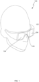
- Figure 1 shows a very simple representation of an HMD shown generally at 100.
- the HMD is wearable by means of an appropriate support 102.
- the support includes one or more optical elements 104 which can be viewed by one of both eyes of the user.
- the HMD further includes a control system (not shown).
- the HMD can be of any appropriate type including googles, glasses, a helmet or helmet visor, or in the form of a handheld device which can be brought in front of the eyes.
- the device is portable or adapted to be portable by means of the support.
- the support may include a support adapted to support the optical elements in front of the eye.
- the support may include: frames; side arms and supports for goggles and glasses; a helmet or visor; a headband; a neck or shoulder worn support; a gaming headset; or any other support that could be worn to hold the optical elements in the desired position.
- the control system is variable depending on the use of the HMD.
- the control unit may be in situ or remote from the HMD.
- the control device may include a communications module for communicating with the optical elements and with other modules either on the HMD or remote therefrom.
- the communications may be wireless and/or wired.
- the control module may include different modules for carrying out different functions. These functions are not limited in any way but may include imaging, tracking, scene generation, processing, storage, power supply, audio etc.
- the optical elements 104 may be any appropriate type. Referring to figure 2 .
- the optical element 200 includes two eyepieces 202, 204 held together by a bridging element 206.
- the eyepieces each include a display medium 208 which relays an image to the eye of the user in use.
- the display medium includes, for example, a waveguide, a lens system, a prism, or other optical components.
- the device is shown as binocular but it is possible that the device could be monocular with one of the display media being replaced with a blank element.
- the optical elements may be adapted for use in the non-optical domain. It will be appreciated therefore that optical is not limited herein to mean visible optical frequencies and may include non-visible frequencies.
- the two eyepieces are separated by a bridging element 206.
- the bridging element may be a band having a combination of a different curvature and a different length.
- the bridging element may have a specific shape to position or orient the eyepieces in a predetermined location. More details of the bridging element are described in greater detail below.
- Each arrangement 200, 200', 200" includes a pair of eyepieces 202, 202', 202" and 204, 204', 204" and a bridging element 206, 206', 206".
- the eyepiece may include an active optical area 208 and a blank area 210.
- the pupil of the eye of a user should be located substantial centrally in the active area for optimal viewing performance.
- the position of the pupil of the user is shown for eyepiece 202, 202', 202" as 212, 212' and 212" respectively.
- the pupil on the other eyepiece is not labelled but is shown.
- IPD interpupillary distance
- IPD interpupillary distance
- the present invention provides a modular assembly including at least one active eyepieces and a plurality of different bridging elements, each of which has a different shape and length to accommodate the differences in the pupil positions and orientations of the user.
- the different lengths of bridging elements 206, 206', 206" can be seen in the different arrangement of figure 2 .
- the bridging element is attached to the two eyepieces by an appropriate connection on each (not shown). This could include a push connecter, a clip or any other type of mechanical clasp, interface, retainer or connection.
- Each bridging element includes an identifier (not shown) which is used to identify one bridging element from the others.
- the identifier could be an active device which communicates its identity to the system.
- the identifier may be an RFID identifier or other type of readable electronic label.
- the identifier may be detectable by the eyepieces and/or the HMD to enable identification of the bridging element for a number of different reasons as will be described below.
- the main purpose of the identifier is to enable the system to determine the combination of eyepieces and bridging element used for a particular user. This is important as the end orientation and position of the eyepieces relative to one another is required to ensure that any image displayed to the HMD is delivered correctly.
- the bridging elements may have different length and curvatures to accommodate different nose shapes and eye positions and orientations on the face.
- the bridging elements are made of material which can retain its shape even when connected and unconnected multiple times. In addition, the bridging element can be reseated as often as necessary. Typical materials may include consumer grade metals, plastics, polymers or rubbers as known in the industry.
- the bridging elements may be connected to the eyepieces by a magnetic connection. This example may only be applicable to uses where magnetic forces will not interfere with the optical and electronic components of the HMD. Again as discussed above the relevant combinations of eyepieces and bridging element are identified by the identifiers to enable the orientation and position of the respective eyepieces.
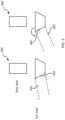
- the position of the bridging elements 300, 300' may be moveable relative to the eyepieces 302, 302' to different angular positions.
- the angle in one instance may be less slanted than that of another orientation as shown in the RHS of the drawing. This could be achieved by having a pivot about which the bridging element can rotate or, as shown, could be based on a particular shape of the bridging element. For example, the bridging element 300 on the LHS is approaching a near rectangle wedge shape in the view from above and the eyepieces are aligned with angled side 304. This produces a certain angular displacement in the orientation of the eyepiece relative to the bridging element.
- the bridging element 300' on the RHS is shaped in the form of a rhombus in the view from above and the eyepieces are aligned with angled side 304', which produces a larger bend in the orientation of the eyepiece relative to the bridging element.
- Different angular alignments can be achieved by using different shaped bridging elements.
- Each different shape or slant of the bridging element may include an identifier as discussed above which gives an indication of the angular orientation of the bridging element relative to the eyepiece. This could be the same or a different RFID or other type of electronic or readable label.
- the HMD can give rise to a wider perceived field of view (FOV) than if the eyepieces were not angularly displaced.
- FOV field of view
- the perceived display FOV will now comprise of a central stereoscopic region where the FOV from each eyepiece overlaps and a FOV region outside of this central region where the FOV from each eyepiece does not overlap. This will typically result in a wider binocular FOV comprising the central FOV region and FOV at the edges of the central region; this will be perceived as a wider FOV by the user.
- the bridging element may be adjustable. Different ways of implementing a variable length bridging element can be envisaged.
- the present invention is aiming to provide a flexible and adjustable HMD which can be adapted for use with different users by adjusting the position and orientation of the eyepieces through a plurality of variable bridging elements.
- the nose pieces may be have one or more differences in terms of shape, size (including variable length), angular orientation and relative position of the respective eyepieces.
- the present invention achieves this through a modular system.
- the modular system includes one or more housing or support modules, a control module (which may be remote), one or more eyepieces, and plurality of bridging elements.
- a HMD may be constructed from any combination of these elements and any number of modules can be provided as a single package to a user. The user then selects the support, eyepieces and bridging element that best suits their needs.
- one user may chose two active eyepieces and a frame that fits their heads and one of the bridging elements. The user then combines the combinations of parts into a HMD that is adapted to their vision. Another user may select one active eyepiece and one "blank" eyepiece and connect the two to side arms for glasses and connect the eyepieces with one of the bridging elements. The combinations are endless and each user can easily adapt the HMD to their required vision and operational requirements.
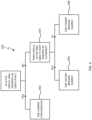
- Figure 4 is a simple flow chart showing how a user might decide which bridging element to use.
- the user puts together a combination of support, eyepieces and bridging element 400. If their visionary requirements are correct (yes), this configuration is used 402. If their visionary requirements are incorrect (no) the process advances to step 404.
- the IPD of the user is assessed to determine in the IPD of the configurations is appropriate for the user. If the configuration is incorrect the nature of the problem is ascertained. A determination is made as to whether the active display area needs to shift inwards or outwards 404. If outwards, a longer or thicker bridging element is selected 406 and if inwards, a shorter or thinner bridging element is selected 408.
- the present invention provides a number of clear advantages, example of which are now discussed.
- An HMD is a relatively expensive piece of equipment and as such it is undesirable to have more than is needed.
- a single set of eyepieces can be provides with multiple bridging elements making the HMD adaptable to all users without having to have a device for each user.
- the configuration is adapted to the IPD of each user by varying the relative position of the eyepieces it is possible to have a smaller active area in each eyepiece as this does not have to be expanded to accommodate users having different IPDs, this has performance benefits. Instead, this is accommodated by a relatively inexpensive set of bridging elements. In some situations it is useful to have only one active eyepiece and in others two are preferable. By having a two or more eyepieces, one of which may be inactive, different configurations may be accommodated. In addition, by having different supports or houses individual preference and other issues such as safety and robustness of the HMD are also provided.
- the present invention relates to an adjustable wearable optic device such as an HMD. It could equally apply to different devices, including but not limited to HWD and other optical devices.
Landscapes
- Physics & Mathematics (AREA)
- General Physics & Mathematics (AREA)
- Optics & Photonics (AREA)
- Health & Medical Sciences (AREA)
- Ophthalmology & Optometry (AREA)
- Lenses (AREA)
- Eyeglasses (AREA)
Claims (10)
- Modulare tragbare Optikvorrichtung (200), die einschließt:mindestens ein tragbares Stützelement;ein oder mehrere aktive Okulare (202, 204), die in Verwendung angepasst sind, um einem Benutzer ein Bild anzuzeigen;ein entfernbares Überbrückungselement (206), das aus einer Vielzahl von Überbrückungselementen ausgewählt ist, das ausgewählt ist, um das eine oder die mehreren aktiven Okulare (202) an einer vorbestimmten Stelle basierend auf einer oder mehreren anthropometrischen Eigenschaften des Benutzers zu positionieren oder auszurichten; wobeidie Vielzahl von Überbrückungselementen (206) unterschiedliche Formen und Größen aufweisen, die jeweils angepasst sind, um die Okulare (202) in einer unterschiedlichen Position oder Ausrichtung zu lokalisieren;dadurch gekennzeichnet, dass das Überbrückungselement (206) eine Kennung einschließt, die eine Identifizierung der Form und der Größe des Überbrückungselements (206) durch ein Steuersystem des einen oder der mehreren aktiven Okulare aktiviert, um dadurch einen oder mehrere Konvergenzparameter des Okulars einzustellen; unddie Kennung eine aktive Vorrichtung ist.
- Modulare tragbare Optikvorrichtung (200) nach Anspruch 1, ferner umfassend ein optisches System, das aktiviert ist, um einen oder mehrere Konvergenzparameter der Okulare (202, 204) einzustellen.
- Modulare tragbare Optikvorrichtung (200) nach einem der vorstehenden Ansprüche, wobei die Okulare (202, 204) angepasst sind, um winkelig verschiebbar zu sein, um ein breiteres Sichtfeld für die Anzeige zu erzeugen.
- Modulare tragbare Optikvorrichtung (200) nach einem der vorstehenden Ansprüche, wobei die anthropometrischen Eigenschaften auf der Pupillendistanz des Benutzers basieren.
- Modulare tragbare Optikvorrichtung (200) nach Anspruch 4, wobei das Überbrückungselement (202, 204) basierend auf der Pupillendistanz des Benutzers ausgewählt ist.
- Modulare tragbare Optikvorrichtung nach einem der vorstehenden Ansprüche, wobei jedes optische Element einen vorbestimmten aktiven optischen Bereich einschließt.
- Modulare tragbare Optikvorrichtung nach Anspruch 6, wobei der aktive Bereich von einem inaktiven Bereich umgeben ist.
- Modulare tragbare Optikvorrichtung nach einem der vorstehenden Ansprüche, wobei das tragbare Stützelement mindestens eines umfasst von einem Rahmen; Seitenarmen und Stützen für Schutzbrillen oder Brillen; einem Helm oder einer Blende; einem Kopfband; einer an dem Hals oder an der Schulter getragenen Stütze; und einem Headset.
- Modulare tragbare Optikvorrichtung nach einem der vorstehenden Ansprüche, wobei jedes Überbrückungselement ein Band ist, das eine Kombination aus einer unterschiedlichen Krümmung und einer unterschiedlichen Länge aufweist.
- Modulare tragbare Optikvorrichtung nach einem der Ansprüche 1 bis 9, wobei das Überbrückungselement ein geformtes Element ist, das angepasst ist, um die Okulare in einer vorbestimmten Position oder Ausrichtung zu stützen.
Applications Claiming Priority (3)
| Application Number | Priority Date | Filing Date | Title |
|---|---|---|---|
| GB1808076.2A GB2573799A (en) | 2018-05-18 | 2018-05-18 | Improvements in or relating to wearable optical devices |
| EP18173242.1A EP3570092A1 (de) | 2018-05-18 | 2018-05-18 | Verbesserungen an oder im zusammenhang mit optischen wearable-vorrichtungen |
| PCT/GB2019/051192 WO2019220075A1 (en) | 2018-05-18 | 2019-04-30 | Improvements in or relating to wearable optical devices |
Publications (2)
| Publication Number | Publication Date |
|---|---|
| EP3794405A1 EP3794405A1 (de) | 2021-03-24 |
| EP3794405B1 true EP3794405B1 (de) | 2023-09-27 |
Family
ID=66290475
Family Applications (1)
| Application Number | Title | Priority Date | Filing Date |
|---|---|---|---|
| EP19719911.0A Active EP3794405B1 (de) | 2018-05-18 | 2019-04-30 | Verbesserungen an oder im zusammenhang mit optischen wearable-vorrichtungen |
Country Status (4)
| Country | Link |
|---|---|
| US (1) | US11886043B2 (de) |
| EP (1) | EP3794405B1 (de) |
| ES (1) | ES2962619T3 (de) |
| WO (1) | WO2019220075A1 (de) |
Families Citing this family (2)
| Publication number | Priority date | Publication date | Assignee | Title |
|---|---|---|---|---|
| EP3794405B1 (de) | 2018-05-18 | 2023-09-27 | BAE SYSTEMS plc | Verbesserungen an oder im zusammenhang mit optischen wearable-vorrichtungen |
| WO2022071975A1 (en) * | 2020-09-29 | 2022-04-07 | Google Llc | Fitting mechanisms for eyewear with visible displays and accomodation of wearer anatomy |
Family Cites Families (12)
| Publication number | Priority date | Publication date | Assignee | Title |
|---|---|---|---|---|
| DE8437992U1 (de) | 1984-12-24 | 1986-02-27 | Steiner, Walter, Bruetten | Sehhilfsgerät, insbesondere Lesehilfsgerät |
| GB2410805A (en) | 2004-02-09 | 2005-08-10 | Paul Teixeira | Eyewear frame with interchangeable bridge |
| US20130079850A1 (en) * | 2010-06-21 | 2013-03-28 | Raphael Darvish | EM Radiation eye protection systems and methods |
| US8971023B2 (en) * | 2012-03-21 | 2015-03-03 | Google Inc. | Wearable computing device frame |
| US9146397B2 (en) * | 2012-05-30 | 2015-09-29 | Microsoft Technology Licensing, Llc | Customized see-through, electronic display device |
| US10423011B2 (en) * | 2012-06-14 | 2019-09-24 | Mitsui Chemicals, Inc. | Lens, lens blank, and eyewear |
| TWM470598U (zh) | 2013-03-15 | 2014-01-21 | jia-jun Mu | 模組化近視泳鏡銷售平台 |
| JP6479785B2 (ja) * | 2013-10-16 | 2019-03-06 | マジック リープ, インコーポレイテッドMagic Leap,Inc. | 調節可能な瞳孔間距離を有する仮想または拡張現実ヘッドセット |
| CN104656284A (zh) | 2015-01-29 | 2015-05-27 | 穆家骏 | 陆地用运动近视眼镜模块化组配系统及组配方法 |
| EP3081981A1 (de) * | 2015-04-17 | 2016-10-19 | Essilor International (Compagnie Generale D'optique) | An einen brillenträger angepasste brille, brillen-kit zur herstellung einer solchen brille und entsprechende herstellungsmethoden |
| US20180364497A1 (en) | 2015-12-03 | 2018-12-20 | Guliana PARIS | Modular eyewear system |
| EP3794405B1 (de) | 2018-05-18 | 2023-09-27 | BAE SYSTEMS plc | Verbesserungen an oder im zusammenhang mit optischen wearable-vorrichtungen |
-
2019
- 2019-04-30 EP EP19719911.0A patent/EP3794405B1/de active Active
- 2019-04-30 ES ES19719911T patent/ES2962619T3/es active Active
- 2019-04-30 US US17/055,393 patent/US11886043B2/en active Active
- 2019-04-30 WO PCT/GB2019/051192 patent/WO2019220075A1/en not_active Ceased
Also Published As
| Publication number | Publication date |
|---|---|
| WO2019220075A1 (en) | 2019-11-21 |
| EP3794405A1 (de) | 2021-03-24 |
| ES2962619T3 (es) | 2024-03-20 |
| US11886043B2 (en) | 2024-01-30 |
| US20210208421A1 (en) | 2021-07-08 |
Similar Documents
| Publication | Publication Date | Title |
|---|---|---|
| US8159751B2 (en) | Apparatus for head mounted image display | |
| KR101939521B1 (ko) | 머리 착용가능 디스플레이를 위한 하이브리드 렌즈 시스템 | |
| EP3513243B1 (de) | Optisches system für ein kopfmontiertes anzeigesystem | |
| EP3368940B1 (de) | Optischer freiraumkombinator mit rezeptintegration | |
| US10495888B2 (en) | Image display device capable of adjusting image position in depth direction | |
| EP3023828B1 (de) | Bildanzeigevorrichtung | |
| US10962782B2 (en) | Exit pupil expansion via curved waveguide | |
| EP3980839A1 (de) | Kopfmontiertes anzeigesystem vom fernglastyp mit verstellbarem augenabstandsmechanismus | |
| JP7753489B2 (ja) | アイウェアデバイス及び方法 | |
| EP3570092A1 (de) | Verbesserungen an oder im zusammenhang mit optischen wearable-vorrichtungen | |
| EP3794405B1 (de) | Verbesserungen an oder im zusammenhang mit optischen wearable-vorrichtungen | |
| EP3200003A1 (de) | 3d-anzeigevorrichtung ohne brille | |
| US12117611B2 (en) | System and method of augmenting a head mounted display for vision correction background | |
| EP2237098B1 (de) | Am Kopf getragenes Anzeigegerät | |
| GB2573799A (en) | Improvements in or relating to wearable optical devices | |
| US20230324687A1 (en) | Wearable optical devices | |
| EP3958039A1 (de) | Verbesserungen an oder im zusammenhang mit optischen wearable-vorrichtungen | |
| EP4310579B1 (de) | Elektronische vorrichtungen mit sensoren mit rückwärtiger verkleidung | |
| CN115943338A (zh) | 可穿戴光学装置中的改进或与可穿戴光学装置相关的改进 | |
| TWM314335U (en) | Head-mounted display based on optical techniques |
Legal Events
| Date | Code | Title | Description |
|---|---|---|---|
| STAA | Information on the status of an ep patent application or granted ep patent |
Free format text: STATUS: UNKNOWN |
|
| STAA | Information on the status of an ep patent application or granted ep patent |
Free format text: STATUS: THE INTERNATIONAL PUBLICATION HAS BEEN MADE |
|
| PUAI | Public reference made under article 153(3) epc to a published international application that has entered the european phase |
Free format text: ORIGINAL CODE: 0009012 |
|
| STAA | Information on the status of an ep patent application or granted ep patent |
Free format text: STATUS: REQUEST FOR EXAMINATION WAS MADE |
|
| 17P | Request for examination filed |
Effective date: 20201210 |
|
| AK | Designated contracting states |
Kind code of ref document: A1 Designated state(s): AL AT BE BG CH CY CZ DE DK EE ES FI FR GB GR HR HU IE IS IT LI LT LU LV MC MK MT NL NO PL PT RO RS SE SI SK SM TR |
|
| AX | Request for extension of the european patent |
Extension state: BA ME |
|
| DAV | Request for validation of the european patent (deleted) | ||
| DAX | Request for extension of the european patent (deleted) | ||
| GRAP | Despatch of communication of intention to grant a patent |
Free format text: ORIGINAL CODE: EPIDOSNIGR1 |
|
| STAA | Information on the status of an ep patent application or granted ep patent |
Free format text: STATUS: GRANT OF PATENT IS INTENDED |
|
| INTG | Intention to grant announced |
Effective date: 20230522 |
|
| RIN1 | Information on inventor provided before grant (corrected) |
Inventor name: MACKEN, IAN THOMAS Inventor name: MILLS, RORY THOMAS ALEXANDER |
|
| GRAS | Grant fee paid |
Free format text: ORIGINAL CODE: EPIDOSNIGR3 |
|
| GRAA | (expected) grant |
Free format text: ORIGINAL CODE: 0009210 |
|
| STAA | Information on the status of an ep patent application or granted ep patent |
Free format text: STATUS: THE PATENT HAS BEEN GRANTED |
|
| AK | Designated contracting states |
Kind code of ref document: B1 Designated state(s): AL AT BE BG CH CY CZ DE DK EE ES FI FR GB GR HR HU IE IS IT LI LT LU LV MC MK MT NL NO PL PT RO RS SE SI SK SM TR |
|
| REG | Reference to a national code |
Ref country code: GB Ref legal event code: FG4D |
|
| REG | Reference to a national code |
Ref country code: CH Ref legal event code: EP |
|
| REG | Reference to a national code |
Ref country code: DE Ref legal event code: R096 Ref document number: 602019038178 Country of ref document: DE |
|
| REG | Reference to a national code |
Ref country code: IE Ref legal event code: FG4D |
|
| REG | Reference to a national code |
Ref country code: LT Ref legal event code: MG9D |
|
| PG25 | Lapsed in a contracting state [announced via postgrant information from national office to epo] |
Ref country code: GR Free format text: LAPSE BECAUSE OF FAILURE TO SUBMIT A TRANSLATION OF THE DESCRIPTION OR TO PAY THE FEE WITHIN THE PRESCRIBED TIME-LIMIT Effective date: 20231228 |
|
| PG25 | Lapsed in a contracting state [announced via postgrant information from national office to epo] |
Ref country code: SE Free format text: LAPSE BECAUSE OF FAILURE TO SUBMIT A TRANSLATION OF THE DESCRIPTION OR TO PAY THE FEE WITHIN THE PRESCRIBED TIME-LIMIT Effective date: 20230927 Ref country code: RS Free format text: LAPSE BECAUSE OF FAILURE TO SUBMIT A TRANSLATION OF THE DESCRIPTION OR TO PAY THE FEE WITHIN THE PRESCRIBED TIME-LIMIT Effective date: 20230927 Ref country code: NO Free format text: LAPSE BECAUSE OF FAILURE TO SUBMIT A TRANSLATION OF THE DESCRIPTION OR TO PAY THE FEE WITHIN THE PRESCRIBED TIME-LIMIT Effective date: 20231227 Ref country code: LV Free format text: LAPSE BECAUSE OF FAILURE TO SUBMIT A TRANSLATION OF THE DESCRIPTION OR TO PAY THE FEE WITHIN THE PRESCRIBED TIME-LIMIT Effective date: 20230927 Ref country code: LT Free format text: LAPSE BECAUSE OF FAILURE TO SUBMIT A TRANSLATION OF THE DESCRIPTION OR TO PAY THE FEE WITHIN THE PRESCRIBED TIME-LIMIT Effective date: 20230927 Ref country code: HR Free format text: LAPSE BECAUSE OF FAILURE TO SUBMIT A TRANSLATION OF THE DESCRIPTION OR TO PAY THE FEE WITHIN THE PRESCRIBED TIME-LIMIT Effective date: 20230927 Ref country code: GR Free format text: LAPSE BECAUSE OF FAILURE TO SUBMIT A TRANSLATION OF THE DESCRIPTION OR TO PAY THE FEE WITHIN THE PRESCRIBED TIME-LIMIT Effective date: 20231228 Ref country code: FI Free format text: LAPSE BECAUSE OF FAILURE TO SUBMIT A TRANSLATION OF THE DESCRIPTION OR TO PAY THE FEE WITHIN THE PRESCRIBED TIME-LIMIT Effective date: 20230927 |
|
| REG | Reference to a national code |
Ref country code: NL Ref legal event code: MP Effective date: 20230927 |
|
| REG | Reference to a national code |
Ref country code: AT Ref legal event code: MK05 Ref document number: 1615989 Country of ref document: AT Kind code of ref document: T Effective date: 20230927 |
|
| PG25 | Lapsed in a contracting state [announced via postgrant information from national office to epo] |
Ref country code: NL Free format text: LAPSE BECAUSE OF FAILURE TO SUBMIT A TRANSLATION OF THE DESCRIPTION OR TO PAY THE FEE WITHIN THE PRESCRIBED TIME-LIMIT Effective date: 20230927 |
|
| REG | Reference to a national code |
Ref country code: ES Ref legal event code: FG2A Ref document number: 2962619 Country of ref document: ES Kind code of ref document: T3 Effective date: 20240320 |
|
| PG25 | Lapsed in a contracting state [announced via postgrant information from national office to epo] |
Ref country code: IS Free format text: LAPSE BECAUSE OF FAILURE TO SUBMIT A TRANSLATION OF THE DESCRIPTION OR TO PAY THE FEE WITHIN THE PRESCRIBED TIME-LIMIT Effective date: 20240127 |
|
| PG25 | Lapsed in a contracting state [announced via postgrant information from national office to epo] |
Ref country code: AT Free format text: LAPSE BECAUSE OF FAILURE TO SUBMIT A TRANSLATION OF THE DESCRIPTION OR TO PAY THE FEE WITHIN THE PRESCRIBED TIME-LIMIT Effective date: 20230927 |
|
| PG25 | Lapsed in a contracting state [announced via postgrant information from national office to epo] |
Ref country code: SM Free format text: LAPSE BECAUSE OF FAILURE TO SUBMIT A TRANSLATION OF THE DESCRIPTION OR TO PAY THE FEE WITHIN THE PRESCRIBED TIME-LIMIT Effective date: 20230927 Ref country code: RO Free format text: LAPSE BECAUSE OF FAILURE TO SUBMIT A TRANSLATION OF THE DESCRIPTION OR TO PAY THE FEE WITHIN THE PRESCRIBED TIME-LIMIT Effective date: 20230927 Ref country code: IS Free format text: LAPSE BECAUSE OF FAILURE TO SUBMIT A TRANSLATION OF THE DESCRIPTION OR TO PAY THE FEE WITHIN THE PRESCRIBED TIME-LIMIT Effective date: 20240127 Ref country code: EE Free format text: LAPSE BECAUSE OF FAILURE TO SUBMIT A TRANSLATION OF THE DESCRIPTION OR TO PAY THE FEE WITHIN THE PRESCRIBED TIME-LIMIT Effective date: 20230927 Ref country code: CZ Free format text: LAPSE BECAUSE OF FAILURE TO SUBMIT A TRANSLATION OF THE DESCRIPTION OR TO PAY THE FEE WITHIN THE PRESCRIBED TIME-LIMIT Effective date: 20230927 Ref country code: AT Free format text: LAPSE BECAUSE OF FAILURE TO SUBMIT A TRANSLATION OF THE DESCRIPTION OR TO PAY THE FEE WITHIN THE PRESCRIBED TIME-LIMIT Effective date: 20230927 Ref country code: SK Free format text: LAPSE BECAUSE OF FAILURE TO SUBMIT A TRANSLATION OF THE DESCRIPTION OR TO PAY THE FEE WITHIN THE PRESCRIBED TIME-LIMIT Effective date: 20230927 Ref country code: PT Free format text: LAPSE BECAUSE OF FAILURE TO SUBMIT A TRANSLATION OF THE DESCRIPTION OR TO PAY THE FEE WITHIN THE PRESCRIBED TIME-LIMIT Effective date: 20240129 |
|
| PG25 | Lapsed in a contracting state [announced via postgrant information from national office to epo] |
Ref country code: PL Free format text: LAPSE BECAUSE OF FAILURE TO SUBMIT A TRANSLATION OF THE DESCRIPTION OR TO PAY THE FEE WITHIN THE PRESCRIBED TIME-LIMIT Effective date: 20230927 |
|
| REG | Reference to a national code |
Ref country code: DE Ref legal event code: R097 Ref document number: 602019038178 Country of ref document: DE |
|
| PG25 | Lapsed in a contracting state [announced via postgrant information from national office to epo] |
Ref country code: DK Free format text: LAPSE BECAUSE OF FAILURE TO SUBMIT A TRANSLATION OF THE DESCRIPTION OR TO PAY THE FEE WITHIN THE PRESCRIBED TIME-LIMIT Effective date: 20230927 |
|
| PG25 | Lapsed in a contracting state [announced via postgrant information from national office to epo] |
Ref country code: DK Free format text: LAPSE BECAUSE OF FAILURE TO SUBMIT A TRANSLATION OF THE DESCRIPTION OR TO PAY THE FEE WITHIN THE PRESCRIBED TIME-LIMIT Effective date: 20230927 |
|
| PLBE | No opposition filed within time limit |
Free format text: ORIGINAL CODE: 0009261 |
|
| STAA | Information on the status of an ep patent application or granted ep patent |
Free format text: STATUS: NO OPPOSITION FILED WITHIN TIME LIMIT |
|
| 26N | No opposition filed |
Effective date: 20240628 |
|
| PG25 | Lapsed in a contracting state [announced via postgrant information from national office to epo] |
Ref country code: SI Free format text: LAPSE BECAUSE OF FAILURE TO SUBMIT A TRANSLATION OF THE DESCRIPTION OR TO PAY THE FEE WITHIN THE PRESCRIBED TIME-LIMIT Effective date: 20230927 |
|
| PG25 | Lapsed in a contracting state [announced via postgrant information from national office to epo] |
Ref country code: SI Free format text: LAPSE BECAUSE OF FAILURE TO SUBMIT A TRANSLATION OF THE DESCRIPTION OR TO PAY THE FEE WITHIN THE PRESCRIBED TIME-LIMIT Effective date: 20230927 |
|
| PG25 | Lapsed in a contracting state [announced via postgrant information from national office to epo] |
Ref country code: BG Free format text: LAPSE BECAUSE OF FAILURE TO SUBMIT A TRANSLATION OF THE DESCRIPTION OR TO PAY THE FEE WITHIN THE PRESCRIBED TIME-LIMIT Effective date: 20230927 |
|
| PG25 | Lapsed in a contracting state [announced via postgrant information from national office to epo] |
Ref country code: MC Free format text: LAPSE BECAUSE OF FAILURE TO SUBMIT A TRANSLATION OF THE DESCRIPTION OR TO PAY THE FEE WITHIN THE PRESCRIBED TIME-LIMIT Effective date: 20230927 |
|
| PG25 | Lapsed in a contracting state [announced via postgrant information from national office to epo] |
Ref country code: MC Free format text: LAPSE BECAUSE OF FAILURE TO SUBMIT A TRANSLATION OF THE DESCRIPTION OR TO PAY THE FEE WITHIN THE PRESCRIBED TIME-LIMIT Effective date: 20230927 Ref country code: BG Free format text: LAPSE BECAUSE OF FAILURE TO SUBMIT A TRANSLATION OF THE DESCRIPTION OR TO PAY THE FEE WITHIN THE PRESCRIBED TIME-LIMIT Effective date: 20230927 |
|
| REG | Reference to a national code |
Ref country code: CH Ref legal event code: PL |
|
| PG25 | Lapsed in a contracting state [announced via postgrant information from national office to epo] |
Ref country code: LU Free format text: LAPSE BECAUSE OF NON-PAYMENT OF DUE FEES Effective date: 20240430 |
|
| REG | Reference to a national code |
Ref country code: BE Ref legal event code: MM Effective date: 20240430 |
|
| PG25 | Lapsed in a contracting state [announced via postgrant information from national office to epo] |
Ref country code: LU Free format text: LAPSE BECAUSE OF NON-PAYMENT OF DUE FEES Effective date: 20240430 |
|
| PG25 | Lapsed in a contracting state [announced via postgrant information from national office to epo] |
Ref country code: BE Free format text: LAPSE BECAUSE OF NON-PAYMENT OF DUE FEES Effective date: 20240430 |
|
| PG25 | Lapsed in a contracting state [announced via postgrant information from national office to epo] |
Ref country code: BE Free format text: LAPSE BECAUSE OF NON-PAYMENT OF DUE FEES Effective date: 20240430 Ref country code: CH Free format text: LAPSE BECAUSE OF NON-PAYMENT OF DUE FEES Effective date: 20240430 |
|
| PG25 | Lapsed in a contracting state [announced via postgrant information from national office to epo] |
Ref country code: IE Free format text: LAPSE BECAUSE OF NON-PAYMENT OF DUE FEES Effective date: 20240430 |
|
| PGFP | Annual fee paid to national office [announced via postgrant information from national office to epo] |
Ref country code: DE Payment date: 20250319 Year of fee payment: 7 |
|
| PGFP | Annual fee paid to national office [announced via postgrant information from national office to epo] |
Ref country code: ES Payment date: 20250502 Year of fee payment: 7 |
|
| PG25 | Lapsed in a contracting state [announced via postgrant information from national office to epo] |
Ref country code: CY Free format text: LAPSE BECAUSE OF FAILURE TO SUBMIT A TRANSLATION OF THE DESCRIPTION OR TO PAY THE FEE WITHIN THE PRESCRIBED TIME-LIMIT; INVALID AB INITIO Effective date: 20190430 |
|
| PG25 | Lapsed in a contracting state [announced via postgrant information from national office to epo] |
Ref country code: HU Free format text: LAPSE BECAUSE OF FAILURE TO SUBMIT A TRANSLATION OF THE DESCRIPTION OR TO PAY THE FEE WITHIN THE PRESCRIBED TIME-LIMIT; INVALID AB INITIO Effective date: 20190430 |
|
| PGFP | Annual fee paid to national office [announced via postgrant information from national office to epo] |
Ref country code: GB Payment date: 20260206 Year of fee payment: 8 |
|
| PGFP | Annual fee paid to national office [announced via postgrant information from national office to epo] |
Ref country code: IT Payment date: 20260319 Year of fee payment: 8 |
|
| PGFP | Annual fee paid to national office [announced via postgrant information from national office to epo] |
Ref country code: FR Payment date: 20260320 Year of fee payment: 8 |
|
| PGFP | Annual fee paid to national office [announced via postgrant information from national office to epo] |
Ref country code: TR Payment date: 20260330 Year of fee payment: 8 |