EP3793450B1 - Occlusive medical device with charged polymer coating - Google Patents
Occlusive medical device with charged polymer coating Download PDFInfo
- Publication number
- EP3793450B1 EP3793450B1 EP19728227.0A EP19728227A EP3793450B1 EP 3793450 B1 EP3793450 B1 EP 3793450B1 EP 19728227 A EP19728227 A EP 19728227A EP 3793450 B1 EP3793450 B1 EP 3793450B1
- Authority
- EP
- European Patent Office
- Prior art keywords
- occlusive
- implant
- expandable framework
- occlusive implant
- fibrinogen
- Prior art date
- Legal status (The legal status is an assumption and is not a legal conclusion. Google has not performed a legal analysis and makes no representation as to the accuracy of the status listed.)
- Active
Links
Images





Classifications
-
- A—HUMAN NECESSITIES
- A61—MEDICAL OR VETERINARY SCIENCE; HYGIENE
- A61B—DIAGNOSIS; SURGERY; IDENTIFICATION
- A61B17/00—Surgical instruments, devices or methods
- A61B17/0057—Implements for plugging an opening in the wall of a hollow or tubular organ, e.g. for sealing a vessel puncture or closing a cardiac septal defect
-
- A—HUMAN NECESSITIES
- A61—MEDICAL OR VETERINARY SCIENCE; HYGIENE
- A61B—DIAGNOSIS; SURGERY; IDENTIFICATION
- A61B17/00—Surgical instruments, devices or methods
- A61B17/12—Surgical instruments, devices or methods for ligaturing or otherwise compressing tubular parts of the body, e.g. blood vessels or umbilical cord
- A61B17/12022—Occluding by internal devices, e.g. balloons or releasable wires
- A61B17/12131—Occluding by internal devices, e.g. balloons or releasable wires characterised by the type of occluding device
- A61B17/12168—Occluding by internal devices, e.g. balloons or releasable wires characterised by the type of occluding device having a mesh structure
- A61B17/12177—Occluding by internal devices, e.g. balloons or releasable wires characterised by the type of occluding device having a mesh structure comprising additional materials, e.g. thrombogenic, having filaments, having fibers or being coated
-
- A—HUMAN NECESSITIES
- A61—MEDICAL OR VETERINARY SCIENCE; HYGIENE
- A61B—DIAGNOSIS; SURGERY; IDENTIFICATION
- A61B17/00—Surgical instruments, devices or methods
- A61B17/12—Surgical instruments, devices or methods for ligaturing or otherwise compressing tubular parts of the body, e.g. blood vessels or umbilical cord
- A61B17/12022—Occluding by internal devices, e.g. balloons or releasable wires
- A61B17/12099—Occluding by internal devices, e.g. balloons or releasable wires characterised by the location of the occluder
- A61B17/12122—Occluding by internal devices, e.g. balloons or releasable wires characterised by the location of the occluder within the heart
-
- A—HUMAN NECESSITIES
- A61—MEDICAL OR VETERINARY SCIENCE; HYGIENE
- A61B—DIAGNOSIS; SURGERY; IDENTIFICATION
- A61B17/00—Surgical instruments, devices or methods
- A61B17/12—Surgical instruments, devices or methods for ligaturing or otherwise compressing tubular parts of the body, e.g. blood vessels or umbilical cord
- A61B17/12022—Occluding by internal devices, e.g. balloons or releasable wires
- A61B17/12131—Occluding by internal devices, e.g. balloons or releasable wires characterised by the type of occluding device
- A61B17/12168—Occluding by internal devices, e.g. balloons or releasable wires characterised by the type of occluding device having a mesh structure
- A61B17/12172—Occluding by internal devices, e.g. balloons or releasable wires characterised by the type of occluding device having a mesh structure having a pre-set deployed three-dimensional shape
-
- A—HUMAN NECESSITIES
- A61—MEDICAL OR VETERINARY SCIENCE; HYGIENE
- A61L—METHODS OR APPARATUS FOR STERILISING MATERIALS OR OBJECTS IN GENERAL; DISINFECTION, STERILISATION OR DEODORISATION OF AIR; CHEMICAL ASPECTS OF BANDAGES, DRESSINGS, ABSORBENT PADS OR SURGICAL ARTICLES; MATERIALS FOR BANDAGES, DRESSINGS, ABSORBENT PADS OR SURGICAL ARTICLES
- A61L31/00—Materials for other surgical articles, e.g. stents, stent-grafts, shunts, surgical drapes, guide wires, materials for adhesion prevention, occluding devices, surgical gloves, tissue fixation devices
- A61L31/08—Materials for coatings
- A61L31/10—Macromolecular materials
-
- A—HUMAN NECESSITIES
- A61—MEDICAL OR VETERINARY SCIENCE; HYGIENE
- A61L—METHODS OR APPARATUS FOR STERILISING MATERIALS OR OBJECTS IN GENERAL; DISINFECTION, STERILISATION OR DEODORISATION OF AIR; CHEMICAL ASPECTS OF BANDAGES, DRESSINGS, ABSORBENT PADS OR SURGICAL ARTICLES; MATERIALS FOR BANDAGES, DRESSINGS, ABSORBENT PADS OR SURGICAL ARTICLES
- A61L33/00—Antithrombogenic treatment of surgical articles, e.g. sutures, catheters, prostheses, or of articles for the manipulation or conditioning of blood; Materials for such treatment
- A61L33/06—Use of macromolecular materials
- A61L33/068—Use of macromolecular materials obtained otherwise than by reactions only involving carbon-to-carbon unsaturated bonds
-
- A—HUMAN NECESSITIES
- A61—MEDICAL OR VETERINARY SCIENCE; HYGIENE
- A61B—DIAGNOSIS; SURGERY; IDENTIFICATION
- A61B17/00—Surgical instruments, devices or methods
- A61B17/0057—Implements for plugging an opening in the wall of a hollow or tubular organ, e.g. for sealing a vessel puncture or closing a cardiac septal defect
- A61B2017/00575—Implements for plugging an opening in the wall of a hollow or tubular organ, e.g. for sealing a vessel puncture or closing a cardiac septal defect for closure at remote site, e.g. closing atrial septum defects
-
- A—HUMAN NECESSITIES
- A61—MEDICAL OR VETERINARY SCIENCE; HYGIENE
- A61B—DIAGNOSIS; SURGERY; IDENTIFICATION
- A61B17/00—Surgical instruments, devices or methods
- A61B17/0057—Implements for plugging an opening in the wall of a hollow or tubular organ, e.g. for sealing a vessel puncture or closing a cardiac septal defect
- A61B2017/00575—Implements for plugging an opening in the wall of a hollow or tubular organ, e.g. for sealing a vessel puncture or closing a cardiac septal defect for closure at remote site, e.g. closing atrial septum defects
- A61B2017/00592—Elastic or resilient implements
-
- A—HUMAN NECESSITIES
- A61—MEDICAL OR VETERINARY SCIENCE; HYGIENE
- A61B—DIAGNOSIS; SURGERY; IDENTIFICATION
- A61B17/00—Surgical instruments, devices or methods
- A61B17/0057—Implements for plugging an opening in the wall of a hollow or tubular organ, e.g. for sealing a vessel puncture or closing a cardiac septal defect
- A61B2017/00575—Implements for plugging an opening in the wall of a hollow or tubular organ, e.g. for sealing a vessel puncture or closing a cardiac septal defect for closure at remote site, e.g. closing atrial septum defects
- A61B2017/00615—Implements with an occluder on one side of the opening and holding means therefor on the other
-
- A—HUMAN NECESSITIES
- A61—MEDICAL OR VETERINARY SCIENCE; HYGIENE
- A61B—DIAGNOSIS; SURGERY; IDENTIFICATION
- A61B17/00—Surgical instruments, devices or methods
- A61B17/0057—Implements for plugging an opening in the wall of a hollow or tubular organ, e.g. for sealing a vessel puncture or closing a cardiac septal defect
- A61B2017/00575—Implements for plugging an opening in the wall of a hollow or tubular organ, e.g. for sealing a vessel puncture or closing a cardiac septal defect for closure at remote site, e.g. closing atrial septum defects
- A61B2017/00632—Occluding a cavity, i.e. closing a blind opening
-
- A—HUMAN NECESSITIES
- A61—MEDICAL OR VETERINARY SCIENCE; HYGIENE
- A61B—DIAGNOSIS; SURGERY; IDENTIFICATION
- A61B17/00—Surgical instruments, devices or methods
- A61B17/0057—Implements for plugging an opening in the wall of a hollow or tubular organ, e.g. for sealing a vessel puncture or closing a cardiac septal defect
- A61B2017/00676—Implements for plugging an opening in the wall of a hollow or tubular organ, e.g. for sealing a vessel puncture or closing a cardiac septal defect promotion of self-sealing of the puncture
Definitions
- the present disclosure pertains to occlusive medical devices. More particularly, the present disclosure pertains to occlusive medical devices usable within the left atrial appendage (LAA).
- LAA left atrial appendage
- the left atrial appendage is a small organ attached to the left atrium of the heart as a pouch-like extension.
- the left atrial appendage may not properly contract with the left atrium, causing stagnant blood to pool within its interior, which can lead to the undesirable formation of thrombi within the left atrial appendage.
- Thrombi forming in the left atrial appendage may break loose from this area and enter the blood stream. Thrombi that migrate through the blood vessels may eventually plug a smaller vessel downstream and thereby contribute to stroke or heart attack.
- Clinical studies have shown that the majority of blood clots in patients with atrial fibrillation are found in the left atrial appendage.
- EP 2 872 051 A1 relates to devices having a cage-like structure that are adapted for implantation into the left atrial appendage and prevent blood clots formed therein from being released into the left atrium as well as methods for manufacturing such devices.
- US 2015/196300 A1 relates to percutaneous medical devices for implantation into the left atrial appendage of a heart.
- US 2007/248640 A1 relates to a method and material composition for introduction into a hollow anatomical structure (HAS) with particular relevance to the venous system in the lower extremities.
- HAS hollow anatomical structure
- An example occlusive implant includes an expandable framework that is configured to shift between a collapsed configuration and an expanded configuration and an occlusive member that is disposed along at least a portion of the expandable framework. At least part of the occlusive implant is negatively charged so as to repel fibrinogen and at least one other part of the occlusive implant is positively charged so as to attract fibrinogen.
- the expandable framework includes a central structure, and an area of the occlusive member proximate the central structure may be treated to repel fibrinogen.
- At least part of the occlusive implant may be configured to carry a negative charge at neutral pH.
- At least part of the occlusive implant includes a polymer that may be negatively charged at neutral pH.
- the polymer that may be negatively charged at neutral pH covers at least part of the occlusive member.
- the polymer that may be negatively charged at neutral pH may be spray coated onto the occlusive member.
- the polymer that may be negatively charged at neutral pH may be physically blended with a material forming the occlusive member.
- the polymer that may be negatively charged at neutral pH may be provided as a copolymer with a material forming the occlusive member.
- the occlusive member may include a polymeric coating covering at least a portion of the expandable framework, and the polymeric coating may be positively charged at neutral pH in order to attract fibrinogen.
- the occlusive member may be formed of polyethylene terephthalate (PET).
- PET polyethylene terephthalate
- the expandable framework may include a plurality of anchor members extending radially outward from the expandable framework.
- the expandable framework and the plurality of anchor members may be formed from a unitary tubular member.
- the expandable framework in the expanded configuration, may be configured to fit into a left atrial appendage (LAA) of a patient's heart.
- LAA left atrial appendage
- a second part of the occlusive implant not configured to repel fibrinogen may be configured to attract fibrinogen.
- An example medical implant for occluding a left atrial appendage (LAA) of a patient's heart includes an expandable framework that is configured to shift between a collapsed configuration and an expanded configuration, an occlusive member that extends over and is supported by at least a portion of the expandable framework, and a coating that disposed over at least part of the occlusive member and is configured to repel fibrinogen.
- LAA left atrial appendage
- the coating that is configured to repel fibrinogen may include a polymer that is negatively charged at neutral pH.
- the occlusive implant has a leading edge, and the coating that is configured to repel fibrinogen may extend over the leading edge.
- the expandable framework may include a central structure, and the coating that is configured to repel fibrinogen may extend over the central structure.
- Another example medical implant for occluding a left atrial appendage (LAA) of a patient's heart includes an expandable framework that is configured to shift between a collapsed configuration and an expanded configuration and an occlusive member that extends over and supported by at least a portion of the expandable framework.
- a first coating that is configured to repel fibrinogen is disposed over a first part of the occlusive member and a second coating that is configured to attract fibrinogen is disposed over a second part of the occlusive member.
- references in the specification to "an embodiment”, “some embodiments”, “other embodiments”, etc. indicate that the embodiment described may include one or more particular features, structures, and/or characteristics. However, such recitations do not necessarily mean that all embodiments include the particular features, structures, and/or characteristics. Additionally, when particular features, structures, and/or characteristics are described in connection with one embodiment, it should be understood that such features, structures, and/or characteristics may also be used connection with other embodiments whether or not explicitly described unless clearly stated to the contrary.
- LAA left atrial appendage
- the occurrence of thrombi in the left atrial appendage (LAA) during atrial fibrillation may be due to stagnancy of blood pooling in the LAA.
- the pooled blood may still be pulled out of the left atrium by the left ventricle, however less effectively due to the irregular contraction of the left atrium caused by atrial fibrillation. Therefore, instead of an active support of the blood flow by a contracting left atrium and left atrial appendage, filling of the left ventricle may depend primarily or solely on the suction effect created by the left ventricle. However, the contraction of the left atrial appendage may not be in sync with the cycle of the left ventricle.
- contraction of the left atrial appendage may be out of phase up to 180 degrees with the left ventricle, which may create significant resistance to the desired flow of blood.
- most left atrial appendage geometries are complex and highly variable, with large irregular surface areas and a narrow ostium or opening compared to the depth of the left atrial appendage.
- FIG. 1 illustrates an example occlusive implant 10.
- the implant 10 may include an expandable framework 12.
- the expandable framework 12 includes a central structure 13, where a number of individual elements 15 forming the expandable framework come together.
- the occlusive implant 10 may also include an occlusive member 14 disposed on, disposed over, disposed about, or covering at least a portion of the expandable framework 12.
- the occlusive member 14 may be disposed on, disposed over, disposed about or cover at least a portion of an outer (or outwardly-facing) surface of the expandable framework 12.
- FIG. 1 further illustrates that the occlusive member 14 may extend only partially along the longitudinal extent of the expandable framework 12. However, this is not intended to be limiting. Rather, the occlusive member 14 may extend along the longitudinal extent of the expandable framework to any degree (e.g., the full longitudinal extend of the expandable framework 12).
- the occlusive member 14 may be permeable or impermeable to blood and/or other fluids, such as water.
- the occlusive member 14 may include a woven, braided and/or knitted material, a fiber, a sheet-like material, a fabric, a polymeric membrane, a metallic or polymeric mesh, a porous filter-like material, or other suitable construction.
- the occlusive member 14 may be formed of a polymeric material.
- a suitable polymeric material is polyethylene terephthalate (PET), which is a thermoplastic polyester.
- PET polyethylene terephthalate
- the occlusive member 14 may prevent thrombi (i.e.
- the occlusive member 14 may promote endothelization after implantation, thereby effectively removing the left atrial appendage from the patient's circulatory system.
- FIG. 1 further illustrates that the expandable framework 12 may include a plurality of anchor members 16 disposed about a periphery of the expandable framework 12.
- the plurality of anchor members 16 may extend radially outward from the expandable framework 12.
- at least some of the plurality of anchor members 16 may each have and/or include a body portion and a tip portion projecting circumferentially therefrom, as shown in FIG. 1 .
- materials for the expandable framework 12 and/or the plurality of anchor members 16 are discussed below.
- the expandable framework 12 and the plurality of anchor members 16 may be integrally formed and/or cut from a unitary member. In some embodiments, the expandable framework 12 and the plurality of anchor members 16 may be integrally formed and/or cut from a unitary tubular member and subsequently formed and/or heat set to a desired shape in the expanded configuration. In some embodiments, the expandable framework 12 and the plurality of anchor members 16 may be integrally formed and/or cut from a unitary flat member, and then rolled or formed into a tubular structure and subsequently formed and/or heat set to the desired shape in the expanded configuration. Some exemplary means and/or methods of making and/or forming the expandable framework 12 include laser cutting, machining, punching, stamping, electro discharge machining (EDM), chemical dissolution, etc. Other means and/or methods are also contemplated.
- the plurality of anchor members 16 disposed along the expandable framework 12 may include two rows of anchor members 16. However, this is not intended to be limiting. Rather, the expandable framework 12 may include a single row of anchor members 16. In other examples, the expandable framework 12 may include more than two rows of anchor members 16. For example, in some instances the expandable framework 12 may include 1, 2, 3, 4 or more rows of anchor members 16.
- FIG. 2 illustrates that the occlusive implant 10 may be inserted and advanced through a body lumen via an occlusive implant delivery system 20.
- FIG. 2 further illustrates the occlusive implant 10 being delivered and positioned within the left atrial appendage 50.
- an occlusive implant delivery system 20 may include a delivery catheter 24 which is guided toward the left atrium via various chambers and lumens of the heart (e.g., the inferior vena cava, the right atrium, etc.) to a position adjacent the left atrial appendage 50.
- the delivery system 20 may include a hub member 22 coupled to a proximal region of the delivery catheter 24.
- the hub member 22 may be manipulated by a clinician to direct the distal end region of the delivery catheter 24 to a position adjacent the left atrial appendage 50.
- an occlusive implant delivery system may include a core wire 18.
- a proximal end of the expandable framework 12 may be configured to releasably attach, join, couple, engage, or otherwise connect to the distal end of the core wire 18.
- an end region of the expandable framework 12 may include a threaded insert coupled thereto.
- the threaded insert may be configured to and/or adapted to couple with, join to, mate with, or otherwise engage a threaded member disposed at the distal end of a core wire 18.
- Other means of releasably coupling and/or engaging the proximal end of the expandable framework 12 to the distal end of the core wire 18 are also contemplated.
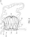
- FIG. 3 illustrates a left atrial appendage occlusive implant 10 positioned adjacent the left atrial appendage 50 via the delivery catheter 24 (described above with respect to FIG. 2 ).
- the implant 10 may be configured to shift between a collapsed configuration and an expanded configuration.
- the occlusive implant may be in a collapsed configuration during delivery via occlusion implant delivery system, whereby the occlusive implant expands to an expanded configuration once deployed from the occlusion implant delivery system.
- FIG. 3 also illustrates several regions of the occlusive implant 10 that tend to attract fibrinogen, and thus encourage the growth of thrombi.
- the central structure 13 tends to be a region that attracts fibrinogen, and thus encourages the growth of thrombi.
- the occlusive implant 10 includes a leading edge 17 that tends to be a region that attracts fibrinogen, and thus encourages the growth of thrombi.
- FIG. 3 illustrates that the expandable framework 12 may be compliant and, therefore, substantially conform to and/or be in sealing engagement with the shape and/or geometry of a lateral wall of a left atrial appendage in the expanded configuration.
- the occlusive implant 10 may expand to a size, extent, or shape less than or different from a maximum unconstrained extent, as determined by the surrounding tissue and/or lateral wall of the left atrial appendage.
- FIG. 3 illustrates that the expandable framework 12 may be held fixed adjacent to the left atrial appendage by one or more anchoring members 16.
- the elements of the expandable framework 12 may be tailored to increase the flexibility and compliance of the expandable framework 12 and/or the occlusive implant 10, thereby permitting the expandable framework 12 and/or the occlusive implant 10 to conform to the tissue around it, rather than forcing the tissue to conform to the expandable framework 12 and/or the occlusive implant 10. Additionally, in some instances, it may be desirable to design the occlusive implant 10 discussed above to include various features, components and/or configurations which improve the sealing capabilities of the occlusive implant within the left atrial appendage.
- At least a portion of the occlusive implant 10 may be treated or otherwise configured to selectively repel fibrinogen, in order to selectively reduce the formation of thrombi relative to certain parts of the occlusive implant 10. In some cases, at least a portion of the occlusive implant 10 may be treated or otherwise configured to selectively attract fibrinogen, in order to selectively encourage the formation of thrombi relative to certain parts of the occlusive implant 10.
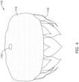
- FIG. 4 shows an occlusive implant 110.
- FIGS. 5 through 8 provide examples of how the occlusive implant 110 may be configured to selectively repel and/or attract fibrinogen.
- the occlusive implant 110 includes an expandable framework 112.
- the expandable framework 112 includes a central structure 113, where a number of individual elements 15 forming the expandable framework come together.
- the occlusive implant 110 may also include an occlusive member 114 disposed on, disposed over, disposed about, or covering at least a portion of the expandable framework 112.
- the occlusive member 114 may be disposed on, disposed over, disposed about or cover at least a portion of an outer (or outwardly-facing) surface of the expandable framework 112.
- FIG. 4 further illustrates that the occlusive member 114 may extend only partially along the longitudinal extent of the expandable framework 112. However, this is not intended to be limiting.
- the occlusive member 114 may extend along the longitudinal extent of the expandable framework to any degree (e.g., the full longitudinal extend of the expandable framework 112).
- the expandable framework 112 may include various features described with respect to the expandable framework 12 ( FIG. 1 )
- the occlusive member 114 may be permeable or impermeable to blood and/or other fluids, such as water.
- the occlusive member 114 may include a woven, braided and/or knitted material, a fiber, a sheet-like material, a fabric, a polymeric membrane, a metallic or polymeric mesh, a porous filter-like material, or other suitable construction.
- the occlusive member 114 may be formed of a polymeric material.
- a suitable polymeric material is polyethylene terephthalate (PET), which is a thermoplastic polyester.
- PET polyethylene terephthalate
- the occlusive member 114 may prevent thrombi (i.e.
- the occlusive member 114 may promote endothelization after implantation, thereby effectively removing the left atrial appendage from the patient's circulatory system.
- the expandable framework 112 may be integrally formed and/or cut from a unitary member. In some embodiments, the expandable framework 112 may be integrally formed and/or cut from a unitary tubular member and subsequently formed and/or heat set to a desired shape in the expanded configuration. In some embodiments, the expandable framework 112 may be integrally formed and/or cut from a unitary flat member, and then rolled or formed into a tubular structure and subsequently formed and/or heat set to the desired shape in the expanded configuration. Some exemplary means and/or methods of making and/or forming the expandable framework 112 include laser cutting, machining, punching, stamping, electro discharge machining (EDM), chemical dissolution, etc. Other means and/or methods are also contemplated.
- the negatively charged region 120 may be formed of a polymer that is negatively charged at neutral pH, such as is found within the blood stream. In this, neutral pH may be defined as ranging from 7.35 and 7.45, which is generally the range within blood pH is maintained by the human body.
- the negatively charged region 120 may be formed by spraying coating onto the occlusive member 114 a polymer that is negatively charged at neutral pH.
- the polymer may instead be physically mixed into the material forming the occlusive member 114.
- the polymer may instead be formed as a copolymer with the material forming the occlusive member 114.
- the occlusive member 114 may be formed of polyethylene terephthalate (PET).
- PET polyethylene terephthalate
- the polymer that is negatively charged at neutral pH may be poly(acrylic acid), carboxymethylcellulose, polystyrene sulfonate, quaternized poly(4-vinyl pyridine) and others.
- a negatively charged surfactant such as a siloxane surfactant may be used.
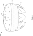
- FIG. 6 it can be seen that there is a negatively charged region 122 that is disposed relative to the occlusive member 114 that spans a larger area than the negatively charged region 120 shown in FIG. 5 . It will be appreciated that the negatively charged region 122 spans the central structure 113 as well as what would be the leading edge (with reference to the leading edge 17 shown in FIG. 3 ). In some cases, since the occlusive implant 110 may be considered as being radially symmetrical, and there may not be a good way to dictate its rotational position relative to the left atrial appendage (LAA) 50, shown in FIG. 3 , having the negatively charged region 122 sized as shown may mean that the leading edge 17 is covered, regardless of the rotational orientation in which the occlusive implant 110 is implanted.
- LAA left atrial appendage
- the negatively charged region 122 may be formed by spraying coating onto the occlusive member 114 a polymer that is negatively charged at neutral pH.
- the polymer may instead be physically mixed into the material forming the occlusive member 114.
- the polymer may instead be formed as a copolymer with the material forming the occlusive member 114.
- the occlusive member 114 may be formed of polyethylene terephthalate (PET).
- PET polyethylene terephthalate
- the polymer that is negatively charged at neutral pH may be poly(acrylic acid), carboxymethylcellulose, polystyrene sulfonate, quaternized poly(4-vinyl pyridine), and others.
- a negatively charged surfactant such as a siloxane surfactant may be used.
- the occlusive implant 110 includes a positively charged region 130.
- providing a positively charged region 130 in this area helps to attract fibrinogen, which tend to be negatively charged at neutral pH. It will be appreciated that by attracting fibrinogen around a periphery 140 of the occlusive implant 110, this can encourage the formation of thrombi and thus encourage endothelization.
- the positively charged region 130 may be formed by spraying coating onto the occlusive member 114 a polymer that is positively charged at neutral pH.
- the polymer may instead be physically mixed into the material forming the occlusive member 114.
- the polymer may instead be formed as a copolymer with the material forming the occlusive member 114.
- the occlusive member 114 may be formed of polyethylene terephthalate (PET).
- the polymer that is positively charged at neutral pH may be one or more of isopropylacrylamide, polysulfone, silicone, dialkyl quaternary ammonium compounds, poly(DMEMA-b-PDMEMA-Co-BMA-Co-PAA), and the like.
- the occlusive implant 110 includes both a negatively charged region 120 and a positively charged region 130. While the negatively charged region 120 and the positively charged region 130 are both shown as discrete regions, it will be appreciated that in some cases there may be a more gradual gradient in charge, i.e., the negatively charged region 120 may vary from a highly negatively charged portion to a lightly negatively charged portion. The positively charged region 120 may vary from a highly positively charged region to a lightly positively charged portion. These are just examples.
- an embolization device may include a positively charged polymer to attract fibrinogen.
- Embolization devices may be used when there is a desire to block blood flow through a particular blood vessel. This may be done, for example, when a particular blood vessel provides blood flow to a tumor, and there is a desire to kill the tumor, or at least reduce its growth.
- FIG. 9 shows an embolization device 150 that generally takes the shape, in an expanded configuration (as shown) of a coil. As will be appreciated, the embolization device 150 is shown schematically as a coil. In some cases, the embolization device 150 may have a more complicated structure.
- the embolization device 150 may be formed from a filar or wire that is coiled into a primary coil, which is then shaped into a secondary coil. Further details regarding the structure of the embolization device 150 may be found in U.S. Patent No. 6,984,240 .
- the embolization device 150 may include a central member 152 that is coated with a positively charged polymer 154.
- the positively charged polymer 154 which may be thought of as being positively charged at neutral pH, may function as an occlusive member by attracting fibrinogen.
- Illustrative but non-limiting examples of materials that may be used in forming the central member 152 include metals such as platinum, stainless steel, zinc, nickle, cobalt, aluminum and aluminum alloys, and Nitinol ® .
- polymers that are positively charged at neutral pH and that may be used are isopropylacrylamide, polysulfone, silicone, dialkyl quaternary ammonium compounds, block polymers such as poly(DMEMA-b-PDMEMA-Co-BMA-Co-PAA) and the like.
- the materials that can be used for the various components of the medical devices disclosed herein may include those commonly associated with medical devices. However, this is not intended to limit the devices and methods described herein, as the discussion may be applied to other components of the occlusive implants 10, 110 disclosed herein.
- the occlusive implants 10, 110 or portions thereof, as well as the embolization device 150 may be made from a metal, metal alloy, polymer (some examples of which are disclosed below), a metal-polymer composite, ceramics, combinations thereof, and the like, or other suitable material.
- suitable polymers may include polytetrafluoroethylene (PTFE), ethylene tetrafluoroethylene (ETFE), fluorinated ethylene propylene (FEP), polyoxymethylene (POM, for example, DELRIN ® available from DuPont), polyether block ester, polyurethane (for example, Polyurethane 85A), polypropylene (PP), polyvinylchloride (PVC), polyether-ester (for example, ARNITEL ® available from DSM Engineering Plastics), ether or ester based copolymers (for example, butylene/poly(alkylene ether) phthalate and/or other polyester elastomers such as HYTREL ® available from DuPont), polyamide (for example, DURETHAN ® available from Bayer or CRISTAMID ® available from Elf Atochem), elastomeric polyamides, block polyamide/ethers, polyether block amide (PEBA, for example available under the trade name PEBAX@),
- suitable metals and metal alloys include stainless steel, such as 304V, 304L, and 316LV stainless steel; mild steel; nickel-titanium alloy such as linear-elastic and/or super-elastic nitinol; other nickel alloys such as nickel-chromium-molybdenum alloys (e.g., UNS: N06625 such as INCONEL ® 625, UNS: N06022 such as HASTELLOY ® C-22 ® , UNS: N10276 such as HASTELLOY ® C276 ® , other HASTELLOY ® alloys, and the like), nickel-copper alloys (e.g., UNS: N04400 such as MONEL ® 400, NICKELVAC ® 400, NICORROS ® 400, and the like), nickel-cobalt-chromium-molybdenum alloys (e.g., UNS: R30035 such as MP35-N ® and the like), nickel-co
- portions or all of the occlusive implants 10, 110 and/or the embolization device 150 may also be doped with, made of, or otherwise include a radiopaque material.
- Radiopaque materials are understood to be materials capable of producing a relatively bright image on a fluoroscopy screen or another imaging technique during a medical procedure. This relatively bright image aids the user in determining its location.
- Some examples of radiopaque materials can include, but are not limited to, gold, platinum, palladium, tantalum, tungsten alloy, polymer material loaded with a radiopaque filler, and the like. Additionally, other radiopaque marker bands and/or coils may also be incorporated into the design of the medical device 10 to achieve the same result.
- a degree of Magnetic Resonance Imaging (MRI) compatibility is imparted into the occlusive implants 10, 110 and/or the embolization device 150.
- the occlusive implants 10, 110 and/or the embolization device 150 may include a material that does not substantially distort the image and create substantial artifacts (e.g., gaps in the image). Certain ferromagnetic materials, for example, may not be suitable because they may create artifacts in an MRI image.
- the occlusive implants 10, 110 and/or the embolization device 150 may also be made from a material that the MRI machine can image.
- Some materials that exhibit these characteristics include, for example, tungsten, cobalt-chromium-molybdenum alloys (e.g., UNS: R30003 such as ELGILOY ® , PHYNOX ® , and the like), nickel-cobalt-chromium-molybdenum alloys (e.g., UNS: R30035 such as MP35-N ® and the like), nitinol, and the like, and others.
- cobalt-chromium-molybdenum alloys e.g., UNS: R30003 such as ELGILOY ® , PHYNOX ® , and the like
- nickel-cobalt-chromium-molybdenum alloys e.g., UNS: R30035 such as MP35-N ® and the like
- nitinol and the like, and others.
- the occlusive implants 10, 110 may include a textile material.
- suitable textile materials may include synthetic yarns that may be flat, shaped, twisted, textured, pre-shrunk or un-shrunk.
- Synthetic biocompatible yarns suitable for use in the present disclosure include, but are not limited to, polyesters, including polyethylene terephthalate (PET) polyesters, polypropylenes, polyethylenes, polyurethanes, polyolefins, polyvinyls, polymethylacetates, polyamides, naphthalene dicarboxylene derivatives, natural silk, and polytetrafluoroethylenes.
- PET polyethylene terephthalate
- the synthetic yarns may be a metallic yarn or a glass or ceramic yarn or fiber.
- Useful metallic yarns include those yarns made from or containing stainless steel, platinum, gold, titanium, tantalum or a Ni-Co-Cr-based alloy.
- the yarns may further include carbon, glass or ceramic fibers.
- the yarns are made from thermoplastic materials including, but not limited to, polyesters, polypropylenes, polyethylenes, polyurethanes, polynaphthalenes, polytetrafluoroethylenes, and the like.
- the yarns may be of the multifilament, monofilament, or spun-types.
- the type and denier of the yarn chosen may be selected in a manner which forms a biocompatible and implantable prosthesis and, more particularly, a vascular structure having desirable properties.
- the occlusive implants 10, 110 may include and/or be treated with a suitable therapeutic agent.
- suitable therapeutic agents may include anti-thrombogenic agents (such as heparin, heparin derivatives, urokinase, and PPack (dextrophenylalanine proline arginine chloromethylketone)); anti-proliferative agents (such as enoxaparin, angiopeptin, monoclonal antibodies capable of blocking smooth muscle cell proliferation, hirudin, and acetylsalicylic acid); anti-inflammatory agents (such as dexamethasone, prednisolone, corticosterone, budesonide, estrogen, sulfasalazine, and mesalamine); antineoplastic/antiproliferative/anti-mitotic agents (such as paclitaxel, 5-fluorouracil, cisplatin, vinblastine, vincristine, e
- anti-thrombogenic agents such as heparin, he
- an occlusive implant for use in the left atrial appendage of the heart
- the aforementioned features may also be useful in other types of medical implants where a fabric or membrane is attached to a frame or support structure including, but not limited to, implants for the treatment of aneurysms (e.g., abdominal aortic aneurysms, thoracic aortic aneurysms, etc.), replacement valve implants (e.g., replacement heart valve implants, replacement aortic valve implants, replacement mitral valve implants, replacement vascular valve implants, etc.), and/or other types of occlusive devices (e.g., atrial septal occluders, cerebral aneurysm occluders, peripheral artery occluders, etc.).
- aneurysms e.g., abdominal aortic aneurysms, thoracic aortic aneurysms, etc.
- replacement valve implants e.g., replacement heart valve implants, replacement
Landscapes
- Health & Medical Sciences (AREA)
- Surgery (AREA)
- Life Sciences & Earth Sciences (AREA)
- Veterinary Medicine (AREA)
- Animal Behavior & Ethology (AREA)
- Public Health (AREA)
- General Health & Medical Sciences (AREA)
- Engineering & Computer Science (AREA)
- Heart & Thoracic Surgery (AREA)
- Vascular Medicine (AREA)
- Biomedical Technology (AREA)
- Molecular Biology (AREA)
- Medical Informatics (AREA)
- Nuclear Medicine, Radiotherapy & Molecular Imaging (AREA)
- Reproductive Health (AREA)
- Epidemiology (AREA)
- Cardiology (AREA)
- Chemical & Material Sciences (AREA)
- Materials Engineering (AREA)
- Hematology (AREA)
- Surgical Instruments (AREA)
- Prostheses (AREA)
Description
- The present disclosure pertains to occlusive medical devices. More particularly, the present disclosure pertains to occlusive medical devices usable within the left atrial appendage (LAA).
- The left atrial appendage (LAA) is a small organ attached to the left atrium of the heart as a pouch-like extension. In some cases, such as in patients suffering from atrial fibrillation, the left atrial appendage may not properly contract with the left atrium, causing stagnant blood to pool within its interior, which can lead to the undesirable formation of thrombi within the left atrial appendage. Thrombi forming in the left atrial appendage may break loose from this area and enter the blood stream. Thrombi that migrate through the blood vessels may eventually plug a smaller vessel downstream and thereby contribute to stroke or heart attack. Clinical studies have shown that the majority of blood clots in patients with atrial fibrillation are found in the left atrial appendage.
- As a treatment, medical devices have been developed which are positioned in the left atrial appendage and deployed to close off the ostium of the left atrial appendage. Over time, the exposed surface(s) spanning the ostium of the left atrial appendage becomes covered with tissue (a process called endothelization), effectively removing the left atrial appendage from the circulatory system and reducing or eliminating the number of thrombi which may enter the blood stream from the left atrial appendage. A continuing need exists for improved medical devices and methods to control thrombus formation within the left atrial appendage of patients suffering from atrial fibrillation.
-
EP 2 872 051 A1 relates to devices having a cage-like structure that are adapted for implantation into the left atrial appendage and prevent blood clots formed therein from being released into the left atrium as well as methods for manufacturing such devices.US 2015/196300 A1 relates to percutaneous medical devices for implantation into the left atrial appendage of a heart.US 2007/248640 A1 relates to a method and material composition for introduction into a hollow anatomical structure (HAS) with particular relevance to the venous system in the lower extremities. - This disclosure provides design, material, manufacturing method, and use alternatives for occlusive medical devices. An example occlusive implant includes an expandable framework that is configured to shift between a collapsed configuration and an expanded configuration and an occlusive member that is disposed along at least a portion of the expandable framework. At least part of the occlusive implant is negatively charged so as to repel fibrinogen and at least one other part of the occlusive implant is positively charged so as to attract fibrinogen.
- Alternatively or additionally, the expandable framework includes a central structure, and an area of the occlusive member proximate the central structure may be treated to repel fibrinogen.
- Alternatively or additionally, at least part of the occlusive implant may be configured to carry a negative charge at neutral pH.
- Alternatively or additionally, at least part of the occlusive implant includes a polymer that may be negatively charged at neutral pH.
- Alternatively or additionally, the polymer that may be negatively charged at neutral pH covers at least part of the occlusive member.
- Alternatively or additionally, the polymer that may be negatively charged at neutral pH may be spray coated onto the occlusive member.
- Alternatively or additionally, the polymer that may be negatively charged at neutral pH may be physically blended with a material forming the occlusive member.
- Alternatively or additionally, the polymer that may be negatively charged at neutral pH may be provided as a copolymer with a material forming the occlusive member.
- Alternatively or additionally, the occlusive member may include a polymeric coating covering at least a portion of the expandable framework, and the polymeric coating may be positively charged at neutral pH in order to attract fibrinogen.
- Alternatively or additionally, the occlusive member may be formed of polyethylene terephthalate (PET).
- Alternatively or additionally, the expandable framework may include a plurality of anchor members extending radially outward from the expandable framework.
- Alternatively or additionally, the expandable framework and the plurality of anchor members may be formed from a unitary tubular member.
- Alternatively or additionally, the expandable framework, in the expanded configuration, may be configured to fit into a left atrial appendage (LAA) of a patient's heart.
- Alternatively or additionally, a second part of the occlusive implant not configured to repel fibrinogen may be configured to attract fibrinogen.
- An example medical implant for occluding a left atrial appendage (LAA) of a patient's heart includes an expandable framework that is configured to shift between a collapsed configuration and an expanded configuration, an occlusive member that extends over and is supported by at least a portion of the expandable framework, and a coating that disposed over at least part of the occlusive member and is configured to repel fibrinogen.
- Alternatively or additionally, the coating that is configured to repel fibrinogen may include a polymer that is negatively charged at neutral pH.
- Alternatively or additionally, the occlusive implant has a leading edge, and the coating that is configured to repel fibrinogen may extend over the leading edge.
- Alternatively or additionally, the expandable framework may include a central structure, and the coating that is configured to repel fibrinogen may extend over the central structure.
- Another example medical implant for occluding a left atrial appendage (LAA) of a patient's heart includes an expandable framework that is configured to shift between a collapsed configuration and an expanded configuration and an occlusive member that extends over and supported by at least a portion of the expandable framework. A first coating that is configured to repel fibrinogen is disposed over a first part of the occlusive member and a second coating that is configured to attract fibrinogen is disposed over a second part of the occlusive member.
- The above summary of some embodiments is not intended to describe each disclosed embodiment or every implementation of the present disclosure. The Figures, and Detailed Description, which follow, more particularly exemplify these embodiments.
- The disclosure may be more completely understood in consideration of the following detailed description in connection with the accompanying drawings, in which:
-
FIG. 1 is a plan view of an example occlusive implant; -
FIG. 2 shows an example occlusive implant positioned in the heart; -
FIG. 3 shows an example occlusive implant positioned in the left atrial appendage; -
FIG. 4 is a plan view of an example occlusive implant; -
FIG. 5 is a plan view of an example occlusive implant; -
FIG. 6 is a plan view of an example occlusive implant; -
FIG. 7 is a plan view of an example occlusive implant; -
FIG. 8 is a plan view of an example occlusive implant; -
FIG. 9 is a plan view of an example embolization device; and -
FIG. 10 is a cross-sectional view of the example embolization device taken along line 10-10 ofFIG. 9 . - While the disclosure is amenable to various modifications and alternative forms, specifics thereof have been shown by way of example in the drawings and will be described in detail. It should be understood, however, that the intention is not to limit the disclosure to the particular embodiments described. On the contrary, the intention is to cover all modifications, equivalents, and alternatives falling within the scope of the disclosure.
- For the following defined terms, these definitions shall be applied, unless a different definition is given in the claims or elsewhere in this specification.
- All numeric values are herein assumed to be modified by the term "about", whether or not explicitly indicated. The term "about" generally refers to a range of numbers that one of skill in the art would consider equivalent to the recited value (e.g., having the same function or result). In many instances, the terms "about" may include numbers that are rounded to the nearest significant figure.
- The recitation of numerical ranges by endpoints includes all numbers within that range (e.g. 1 to 5 includes 1, 1.5, 2, 2.75, 3, 3.80, 4, and 5).
- As used in this specification and the appended claims, the singular forms "a", "an", and "the" include plural referents unless the content clearly dictates otherwise. As used in this specification and the appended claims, the term "or" is generally employed in its sense including "and/or" unless the content clearly dictates otherwise.
- It is noted that references in the specification to "an embodiment", "some embodiments", "other embodiments", etc., indicate that the embodiment described may include one or more particular features, structures, and/or characteristics. However, such recitations do not necessarily mean that all embodiments include the particular features, structures, and/or characteristics. Additionally, when particular features, structures, and/or characteristics are described in connection with one embodiment, it should be understood that such features, structures, and/or characteristics may also be used connection with other embodiments whether or not explicitly described unless clearly stated to the contrary.
- The following detailed description should be read with reference to the drawings in which similar elements in different drawings are numbered the same. The drawings, which are not necessarily to scale, depict illustrative embodiments and are not intended to limit the scope of the invention.
- The occurrence of thrombi in the left atrial appendage (LAA) during atrial fibrillation may be due to stagnancy of blood pooling in the LAA. The pooled blood may still be pulled out of the left atrium by the left ventricle, however less effectively due to the irregular contraction of the left atrium caused by atrial fibrillation. Therefore, instead of an active support of the blood flow by a contracting left atrium and left atrial appendage, filling of the left ventricle may depend primarily or solely on the suction effect created by the left ventricle. However, the contraction of the left atrial appendage may not be in sync with the cycle of the left ventricle. For example, contraction of the left atrial appendage may be out of phase up to 180 degrees with the left ventricle, which may create significant resistance to the desired flow of blood. Further still, most left atrial appendage geometries are complex and highly variable, with large irregular surface areas and a narrow ostium or opening compared to the depth of the left atrial appendage. These aspects as well as others, taken individually or in various combinations, may lead to high flow resistance of blood out of the left atrial appendage.
- In an effort to reduce the occurrence of thrombi formation within the left atrial appendage and prevent thrombi from entering the blood stream from within the left atrial appendage, it may be desirable to develop medical devices and/or occlusive implants that close off the left atrial appendage from the heart and/or circulatory system, thereby lowering the risk of stroke due to thrombolytic material entering the blood stream from the left atrial appendage. In some cases, fibrinogen circulating within the blood contributes to the formation and growth of thrombi. Example medical devices and/or occlusive implants that close off the left atrial appendage are disclosed herein.
-
FIG. 1 illustrates anexample occlusive implant 10. Theimplant 10 may include anexpandable framework 12. In some cases, theexpandable framework 12 includes acentral structure 13, where a number ofindividual elements 15 forming the expandable framework come together. Theocclusive implant 10 may also include anocclusive member 14 disposed on, disposed over, disposed about, or covering at least a portion of theexpandable framework 12. In some embodiments, theocclusive member 14 may be disposed on, disposed over, disposed about or cover at least a portion of an outer (or outwardly-facing) surface of theexpandable framework 12.FIG. 1 further illustrates that theocclusive member 14 may extend only partially along the longitudinal extent of theexpandable framework 12. However, this is not intended to be limiting. Rather, theocclusive member 14 may extend along the longitudinal extent of the expandable framework to any degree (e.g., the full longitudinal extend of the expandable framework 12). - In some embodiments, the
occlusive member 14 may be permeable or impermeable to blood and/or other fluids, such as water. In some embodiments, theocclusive member 14 may include a woven, braided and/or knitted material, a fiber, a sheet-like material, a fabric, a polymeric membrane, a metallic or polymeric mesh, a porous filter-like material, or other suitable construction. In some cases, theocclusive member 14 may be formed of a polymeric material. A suitable polymeric material is polyethylene terephthalate (PET), which is a thermoplastic polyester. In some embodiments, theocclusive member 14 may prevent thrombi (i.e. blood clots, etc.) from passing through theocclusive member 14 and out of the left atrial appendage into the blood stream. In some embodiments, theocclusive member 14 may promote endothelization after implantation, thereby effectively removing the left atrial appendage from the patient's circulatory system. Some suitable, but non-limiting, examples of materials for theocclusive member 14 are discussed below. -
FIG. 1 further illustrates that theexpandable framework 12 may include a plurality ofanchor members 16 disposed about a periphery of theexpandable framework 12. The plurality ofanchor members 16 may extend radially outward from theexpandable framework 12. In some embodiments, at least some of the plurality ofanchor members 16 may each have and/or include a body portion and a tip portion projecting circumferentially therefrom, as shown inFIG. 1 . Some suitable, but non-limiting, examples of materials for theexpandable framework 12 and/or the plurality ofanchor members 16 are discussed below. - In some examples, the
expandable framework 12 and the plurality ofanchor members 16 may be integrally formed and/or cut from a unitary member. In some embodiments, theexpandable framework 12 and the plurality ofanchor members 16 may be integrally formed and/or cut from a unitary tubular member and subsequently formed and/or heat set to a desired shape in the expanded configuration. In some embodiments, theexpandable framework 12 and the plurality ofanchor members 16 may be integrally formed and/or cut from a unitary flat member, and then rolled or formed into a tubular structure and subsequently formed and/or heat set to the desired shape in the expanded configuration. Some exemplary means and/or methods of making and/or forming theexpandable framework 12 include laser cutting, machining, punching, stamping, electro discharge machining (EDM), chemical dissolution, etc. Other means and/or methods are also contemplated. - As illustrated in
FIG. 1 , the plurality ofanchor members 16 disposed along theexpandable framework 12 may include two rows ofanchor members 16. However, this is not intended to be limiting. Rather, theexpandable framework 12 may include a single row ofanchor members 16. In other examples, theexpandable framework 12 may include more than two rows ofanchor members 16. For example, in some instances theexpandable framework 12 may include 1, 2, 3, 4 or more rows ofanchor members 16. -
FIG. 2 illustrates that theocclusive implant 10 may be inserted and advanced through a body lumen via an occlusiveimplant delivery system 20.FIG. 2 further illustrates theocclusive implant 10 being delivered and positioned within the leftatrial appendage 50. In some instances, an occlusiveimplant delivery system 20 may include adelivery catheter 24 which is guided toward the left atrium via various chambers and lumens of the heart (e.g., the inferior vena cava, the right atrium, etc.) to a position adjacent the leftatrial appendage 50. - The
delivery system 20 may include ahub member 22 coupled to a proximal region of thedelivery catheter 24. Thehub member 22 may be manipulated by a clinician to direct the distal end region of thedelivery catheter 24 to a position adjacent the leftatrial appendage 50. In some embodiments, an occlusive implant delivery system may include acore wire 18. Further, a proximal end of theexpandable framework 12 may be configured to releasably attach, join, couple, engage, or otherwise connect to the distal end of thecore wire 18. In some embodiments, an end region of theexpandable framework 12 may include a threaded insert coupled thereto. In some embodiments, the threaded insert may be configured to and/or adapted to couple with, join to, mate with, or otherwise engage a threaded member disposed at the distal end of acore wire 18. Other means of releasably coupling and/or engaging the proximal end of theexpandable framework 12 to the distal end of thecore wire 18 are also contemplated. -
FIG. 3 illustrates a left atrialappendage occlusive implant 10 positioned adjacent the leftatrial appendage 50 via the delivery catheter 24 (described above with respect toFIG. 2 ). As discussed above, in some examples, theimplant 10 may be configured to shift between a collapsed configuration and an expanded configuration. For example, in some instances, the occlusive implant may be in a collapsed configuration during delivery via occlusion implant delivery system, whereby the occlusive implant expands to an expanded configuration once deployed from the occlusion implant delivery system.FIG. 3 also illustrates several regions of theocclusive implant 10 that tend to attract fibrinogen, and thus encourage the growth of thrombi. In some cases, thecentral structure 13 tends to be a region that attracts fibrinogen, and thus encourages the growth of thrombi. Theocclusive implant 10 includes aleading edge 17 that tends to be a region that attracts fibrinogen, and thus encourages the growth of thrombi. - Additionally,
FIG. 3 illustrates that theexpandable framework 12 may be compliant and, therefore, substantially conform to and/or be in sealing engagement with the shape and/or geometry of a lateral wall of a left atrial appendage in the expanded configuration. In some embodiments, theocclusive implant 10 may expand to a size, extent, or shape less than or different from a maximum unconstrained extent, as determined by the surrounding tissue and/or lateral wall of the left atrial appendage. Additionally,FIG. 3 illustrates that theexpandable framework 12 may be held fixed adjacent to the left atrial appendage by one ormore anchoring members 16. - Further, it can be appreciated that the elements of the
expandable framework 12 may be tailored to increase the flexibility and compliance of theexpandable framework 12 and/or theocclusive implant 10, thereby permitting theexpandable framework 12 and/or theocclusive implant 10 to conform to the tissue around it, rather than forcing the tissue to conform to theexpandable framework 12 and/or theocclusive implant 10. Additionally, in some instances, it may be desirable to design theocclusive implant 10 discussed above to include various features, components and/or configurations which improve the sealing capabilities of the occlusive implant within the left atrial appendage. - In some cases, at least a portion of the
occlusive implant 10 may be treated or otherwise configured to selectively repel fibrinogen, in order to selectively reduce the formation of thrombi relative to certain parts of theocclusive implant 10. In some cases, at least a portion of theocclusive implant 10 may be treated or otherwise configured to selectively attract fibrinogen, in order to selectively encourage the formation of thrombi relative to certain parts of theocclusive implant 10.FIG. 4 shows anocclusive implant 110.FIGS. 5 through 8 provide examples of how theocclusive implant 110 may be configured to selectively repel and/or attract fibrinogen. - In
FIG. 4 , theocclusive implant 110 includes anexpandable framework 112. In some cases, theexpandable framework 112 includes acentral structure 113, where a number ofindividual elements 15 forming the expandable framework come together. Theocclusive implant 110 may also include anocclusive member 114 disposed on, disposed over, disposed about, or covering at least a portion of theexpandable framework 112. In some embodiments, theocclusive member 114 may be disposed on, disposed over, disposed about or cover at least a portion of an outer (or outwardly-facing) surface of theexpandable framework 112.FIG. 4 further illustrates that theocclusive member 114 may extend only partially along the longitudinal extent of theexpandable framework 112. However, this is not intended to be limiting. Rather, theocclusive member 114 may extend along the longitudinal extent of the expandable framework to any degree (e.g., the full longitudinal extend of the expandable framework 112). In some cases, theexpandable framework 112 may include various features described with respect to the expandable framework 12 (FIG. 1 ) - In some embodiments, the
occlusive member 114 may be permeable or impermeable to blood and/or other fluids, such as water. In some embodiments, theocclusive member 114 may include a woven, braided and/or knitted material, a fiber, a sheet-like material, a fabric, a polymeric membrane, a metallic or polymeric mesh, a porous filter-like material, or other suitable construction. In some cases, theocclusive member 114 may be formed of a polymeric material. A suitable polymeric material is polyethylene terephthalate (PET), which is a thermoplastic polyester. In some embodiments, theocclusive member 114 may prevent thrombi (i.e. blood clots, etc.) from passing through theocclusive member 114 and out of the left atrial appendage into the blood stream. In some embodiments, theocclusive member 114 may promote endothelization after implantation, thereby effectively removing the left atrial appendage from the patient's circulatory system. Some suitable, but non-limiting, examples of materials for theocclusive member 14 are discussed below. - In some examples, the
expandable framework 112 may be integrally formed and/or cut from a unitary member. In some embodiments, theexpandable framework 112 may be integrally formed and/or cut from a unitary tubular member and subsequently formed and/or heat set to a desired shape in the expanded configuration. In some embodiments, theexpandable framework 112 may be integrally formed and/or cut from a unitary flat member, and then rolled or formed into a tubular structure and subsequently formed and/or heat set to the desired shape in the expanded configuration. Some exemplary means and/or methods of making and/or forming theexpandable framework 112 include laser cutting, machining, punching, stamping, electro discharge machining (EDM), chemical dissolution, etc. Other means and/or methods are also contemplated. - In
FIG. 5 , it can be seen that there is a negatively chargedregion 120 that is disposed relative to theocclusive member 114, proximate thecentral structure 113. In some cases, providing a negatively chargedregion 120 in this area helps to repel fibrinogen, which tend to be negatively charged at neutral pH. It will be appreciated that by repelling fibrinogen in the area around thecentral structure 113, this can reduce or eliminate the formation of thrombi that would otherwise form in this area. Since the remaining portion of theocclusive member 114 does not include the negatively chargedregion 120, thrombi and other tissue growth may be permitted. In some cases, the negatively chargedregion 120 may be formed of a polymer that is negatively charged at neutral pH, such as is found within the blood stream. In this, neutral pH may be defined as ranging from 7.35 and 7.45, which is generally the range within blood pH is maintained by the human body. - In some cases, the negatively charged
region 120 may be formed by spraying coating onto the occlusive member 114 a polymer that is negatively charged at neutral pH. In some cases, the polymer may instead be physically mixed into the material forming theocclusive member 114. In some instances, the polymer may instead be formed as a copolymer with the material forming theocclusive member 114. In some cases, for example, theocclusive member 114 may be formed of polyethylene terephthalate (PET). The polymer that is negatively charged at neutral pH may be poly(acrylic acid), carboxymethylcellulose, polystyrene sulfonate, quaternized poly(4-vinyl pyridine) and others. In some cases, a negatively charged surfactant such as a siloxane surfactant may be used. - In
FIG. 6 , it can be seen that there is a negatively chargedregion 122 that is disposed relative to theocclusive member 114 that spans a larger area than the negatively chargedregion 120 shown inFIG. 5 . It will be appreciated that the negatively chargedregion 122 spans thecentral structure 113 as well as what would be the leading edge (with reference to the leadingedge 17 shown inFIG. 3 ). In some cases, since theocclusive implant 110 may be considered as being radially symmetrical, and there may not be a good way to dictate its rotational position relative to the left atrial appendage (LAA) 50, shown inFIG. 3 , having the negatively chargedregion 122 sized as shown may mean that the leadingedge 17 is covered, regardless of the rotational orientation in which theocclusive implant 110 is implanted. - In some cases, the negatively charged
region 122 may be formed by spraying coating onto the occlusive member 114 a polymer that is negatively charged at neutral pH. In some cases, the polymer may instead be physically mixed into the material forming theocclusive member 114. In some instances, the polymer may instead be formed as a copolymer with the material forming theocclusive member 114. In some cases, for example, theocclusive member 114 may be formed of polyethylene terephthalate (PET). The polymer that is negatively charged at neutral pH may be poly(acrylic acid), carboxymethylcellulose, polystyrene sulfonate, quaternized poly(4-vinyl pyridine), and others. In some cases, a negatively charged surfactant such as a siloxane surfactant may be used. - In some cases, there may be a desire to encourage the formation of thrombi in particular regions of the
occlusive implant 110. InFIG. 7 , theocclusive implant 110 includes a positively chargedregion 130. In some cases, providing a positively chargedregion 130 in this area helps to attract fibrinogen, which tend to be negatively charged at neutral pH. It will be appreciated that by attracting fibrinogen around aperiphery 140 of theocclusive implant 110, this can encourage the formation of thrombi and thus encourage endothelization. In some cases, there is a desire to encourage endothelization that begins around theperiphery 140 and extends inwardly. - In some cases, the positively charged
region 130 may be formed by spraying coating onto the occlusive member 114 a polymer that is positively charged at neutral pH. In some cases, the polymer may instead be physically mixed into the material forming theocclusive member 114. In some instances, the polymer may instead be formed as a copolymer with the material forming theocclusive member 114. In some cases, for example, theocclusive member 114 may be formed of polyethylene terephthalate (PET). The polymer that is positively charged at neutral pH may be one or more of isopropylacrylamide, polysulfone, silicone, dialkyl quaternary ammonium compounds, poly(DMEMA-b-PDMEMA-Co-BMA-Co-PAA), and the like. - In some cases, as shown in
FIG. 8 , there may be a desire to discourage endothelization on some portions of theocclusive implant 110 and to encourage endothelization on other portions of theocclusive implant 110. InFIG. 8 , it can be seen that theocclusive implant 110 includes both a negatively chargedregion 120 and a positively chargedregion 130. While the negatively chargedregion 120 and the positively chargedregion 130 are both shown as discrete regions, it will be appreciated that in some cases there may be a more gradual gradient in charge, i.e., the negatively chargedregion 120 may vary from a highly negatively charged portion to a lightly negatively charged portion. The positively chargedregion 120 may vary from a highly positively charged region to a lightly positively charged portion. These are just examples. - In some cases, an embolization device may include a positively charged polymer to attract fibrinogen. Embolization devices may be used when there is a desire to block blood flow through a particular blood vessel. This may be done, for example, when a particular blood vessel provides blood flow to a tumor, and there is a desire to kill the tumor, or at least reduce its growth.
FIG. 9 shows anembolization device 150 that generally takes the shape, in an expanded configuration (as shown) of a coil. As will be appreciated, theembolization device 150 is shown schematically as a coil. In some cases, theembolization device 150 may have a more complicated structure. For example, theembolization device 150 may be formed from a filar or wire that is coiled into a primary coil, which is then shaped into a secondary coil. Further details regarding the structure of theembolization device 150 may be found inU.S. Patent No. 6,984,240 . - As can be seen by the cross-section shown in
FIG. 10 , theembolization device 150 may include acentral member 152 that is coated with a positively chargedpolymer 154. In some cases, the positively chargedpolymer 154, which may be thought of as being positively charged at neutral pH, may function as an occlusive member by attracting fibrinogen. Illustrative but non-limiting examples of materials that may be used in forming thecentral member 152 include metals such as platinum, stainless steel, zinc, nickle, cobalt, aluminum and aluminum alloys, and Nitinol®. Illustrative but non-limiting examples of polymers that are positively charged at neutral pH and that may be used are isopropylacrylamide, polysulfone, silicone, dialkyl quaternary ammonium compounds, block polymers such as poly(DMEMA-b-PDMEMA-Co-BMA-Co-PAA) and the like. - The materials that can be used for the various components of the medical devices disclosed herein may include those commonly associated with medical devices. However, this is not intended to limit the devices and methods described herein, as the discussion may be applied to other components of the
occlusive implants - The
occlusive implants embolization device 150, may be made from a metal, metal alloy, polymer (some examples of which are disclosed below), a metal-polymer composite, ceramics, combinations thereof, and the like, or other suitable material. Some examples of suitable polymers may include polytetrafluoroethylene (PTFE), ethylene tetrafluoroethylene (ETFE), fluorinated ethylene propylene (FEP), polyoxymethylene (POM, for example, DELRIN® available from DuPont), polyether block ester, polyurethane (for example, Polyurethane 85A), polypropylene (PP), polyvinylchloride (PVC), polyether-ester (for example, ARNITEL® available from DSM Engineering Plastics), ether or ester based copolymers (for example, butylene/poly(alkylene ether) phthalate and/or other polyester elastomers such as HYTREL® available from DuPont), polyamide (for example, DURETHAN® available from Bayer or CRISTAMID® available from Elf Atochem), elastomeric polyamides, block polyamide/ethers, polyether block amide (PEBA, for example available under the trade name PEBAX@), ethylene vinyl acetate copolymers (EVA), silicones, polyethylene (PE), high density polyethylene (HDPE), polyester, Marlex high-density polyethylene, Marlex low-density polyethylene, linear low density polyethylene (for example REXELL®), ultra-high molecular weight (UHMW) polyethylene, polypropylene, polybutylene terephthalate (PBT), polyethylene terephthalate (PET), polytrimethylene terephthalate, polyethylene naphthalate (PEN), polyetheretherketone (PEEK), polyimide (PI), polyetherimide (PEI), polyphenylene sulfide (PPS), polyphenylene oxide (PPO), poly paraphenylene terephthalamide (for example, KEVLAR®), polysulfone, nylon, nylon-12 (such as GRILAMID® available from EMS American Grilon), perfluoro(propyl vinyl ether) (PFA), ethylene vinyl alcohol, polyolefin, polystyrene, epoxy, polyvinylidene chloride (PVdC), poly(styrene-b-isobutylene-b-styrene) (for example, SIBS and/or SIBS 50A), polycarbonates, ionomers, biocompatible polymers, other suitable materials, or mixtures, combinations, copolymers thereof, polymer/metal composites, and the like. In some embodiments the sheath can be blended with a liquid crystal polymer (LCP). - Some examples of suitable metals and metal alloys include stainless steel, such as 304V, 304L, and 316LV stainless steel; mild steel; nickel-titanium alloy such as linear-elastic and/or super-elastic nitinol; other nickel alloys such as nickel-chromium-molybdenum alloys (e.g., UNS: N06625 such as INCONEL® 625, UNS: N06022 such as HASTELLOY® C-22®, UNS: N10276 such as HASTELLOY® C276®, other HASTELLOY® alloys, and the like), nickel-copper alloys (e.g., UNS: N04400 such as MONEL® 400, NICKELVAC® 400, NICORROS® 400, and the like), nickel-cobalt-chromium-molybdenum alloys (e.g., UNS: R30035 such as MP35-N® and the like), nickel-molybdenum alloys (e.g., UNS: N10665 such as HASTELLOY® ALLOY B2®), other nickel-chromium alloys, other nickel-molybdenum alloys, other nickel-cobalt alloys, other nickel-iron alloys, other nickel-copper alloys, other nickel-tungsten or tungsten alloys, and the like; cobalt-chromium alloys; cobalt-chromium-molybdenum alloys (e.g., UNS: R30003 such as ELGILOY®, PHYNOX®, and the like); platinum enriched stainless steel; titanium; combinations thereof; and the like; or any other suitable material.
- In at least some embodiments, portions or all of the
occlusive implants embolization device 150 may also be doped with, made of, or otherwise include a radiopaque material. Radiopaque materials are understood to be materials capable of producing a relatively bright image on a fluoroscopy screen or another imaging technique during a medical procedure. This relatively bright image aids the user in determining its location. Some examples of radiopaque materials can include, but are not limited to, gold, platinum, palladium, tantalum, tungsten alloy, polymer material loaded with a radiopaque filler, and the like. Additionally, other radiopaque marker bands and/or coils may also be incorporated into the design of themedical device 10 to achieve the same result. - In some embodiments, a degree of Magnetic Resonance Imaging (MRI) compatibility is imparted into the
occlusive implants embolization device 150. For example, theocclusive implants embolization device 150 may include a material that does not substantially distort the image and create substantial artifacts (e.g., gaps in the image). Certain ferromagnetic materials, for example, may not be suitable because they may create artifacts in an MRI image. Theocclusive implants embolization device 150 may also be made from a material that the MRI machine can image. Some materials that exhibit these characteristics include, for example, tungsten, cobalt-chromium-molybdenum alloys (e.g., UNS: R30003 such as ELGILOY®, PHYNOX®, and the like), nickel-cobalt-chromium-molybdenum alloys (e.g., UNS: R30035 such as MP35-N® and the like), nitinol, and the like, and others. - In some embodiments, the
occlusive implants 10, 110 (and variations, systems or components thereof disclosed herein) may include a textile material. Some examples of suitable textile materials may include synthetic yarns that may be flat, shaped, twisted, textured, pre-shrunk or un-shrunk. Synthetic biocompatible yarns suitable for use in the present disclosure include, but are not limited to, polyesters, including polyethylene terephthalate (PET) polyesters, polypropylenes, polyethylenes, polyurethanes, polyolefins, polyvinyls, polymethylacetates, polyamides, naphthalene dicarboxylene derivatives, natural silk, and polytetrafluoroethylenes. Moreover, at least one of the synthetic yarns may be a metallic yarn or a glass or ceramic yarn or fiber. Useful metallic yarns include those yarns made from or containing stainless steel, platinum, gold, titanium, tantalum or a Ni-Co-Cr-based alloy. The yarns may further include carbon, glass or ceramic fibers. Desirably, the yarns are made from thermoplastic materials including, but not limited to, polyesters, polypropylenes, polyethylenes, polyurethanes, polynaphthalenes, polytetrafluoroethylenes, and the like. The yarns may be of the multifilament, monofilament, or spun-types. The type and denier of the yarn chosen may be selected in a manner which forms a biocompatible and implantable prosthesis and, more particularly, a vascular structure having desirable properties. - In some embodiments, the
occlusive implants 10, 110 (and variations, systems or components thereof disclosed herein) may include and/or be treated with a suitable therapeutic agent. Some examples of suitable therapeutic agents may include anti-thrombogenic agents (such as heparin, heparin derivatives, urokinase, and PPack (dextrophenylalanine proline arginine chloromethylketone)); anti-proliferative agents (such as enoxaparin, angiopeptin, monoclonal antibodies capable of blocking smooth muscle cell proliferation, hirudin, and acetylsalicylic acid); anti-inflammatory agents (such as dexamethasone, prednisolone, corticosterone, budesonide, estrogen, sulfasalazine, and mesalamine); antineoplastic/antiproliferative/anti-mitotic agents (such as paclitaxel, 5-fluorouracil, cisplatin, vinblastine, vincristine, epothilones, endostatin, angiostatin and thymidine kinase inhibitors); anesthetic agents (such as lidocaine, bupivacaine, and ropivacaine); anti-coagulants (such as D-Phe-Pro-Arg chloromethyl keton, an RGD peptide-containing compound, heparin, anti-thrombin compounds, platelet receptor antagonists, anti-thrombin antibodies, anti-platelet receptor antibodies, aspirin, prostaglandin inhibitors, platelet inhibitors, and tick antiplatelet peptides); vascular cell growth promoters (such as growth factor inhibitors, growth factor receptor antagonists, transcriptional activators, and translational promoters); vascular cell growth inhibitors (such as growth factor inhibitors, growth factor receptor antagonists, transcriptional repressors, translational repressors, replication inhibitors, inhibitory antibodies, antibodies directed against growth factors, bifunctional molecules consisting of a growth factor and a cytotoxin, bifunctional molecules consisting of an antibody and a cytotoxin); cholesterol-lowering agents; vasodilating agents; and agents which interfere with endogenous vascoactive mechanisms. - While the discussion above is generally directed toward an occlusive implant for use in the left atrial appendage of the heart, the aforementioned features may also be useful in other types of medical implants where a fabric or membrane is attached to a frame or support structure including, but not limited to, implants for the treatment of aneurysms (e.g., abdominal aortic aneurysms, thoracic aortic aneurysms, etc.), replacement valve implants (e.g., replacement heart valve implants, replacement aortic valve implants, replacement mitral valve implants, replacement vascular valve implants, etc.), and/or other types of occlusive devices (e.g., atrial septal occluders, cerebral aneurysm occluders, peripheral artery occluders, etc.). Other useful applications of the disclosed features are also contemplated.
Claims (9)
- An occlusive implant (10; 110), comprising:an expandable framework (12; 112) configured to shift between a collapsed configuration and an expanded configuration; andan occlusive member (14; 114) disposed along at least a portion of the expandable framework (12; 112);said occlusive implant being characterized in that at least one part of the occlusive implant (10; 110) is negatively charged so as to repel fibrinogen and at least one other part of the occlusive implant (10; 110) is positively charged so as to attract fibrinogen.
- The occlusive implant (10; 110) of claim 1, wherein the occlusive implant (10; 110) has a leading edge (17), and an area of the occlusive member (10; 110) proximate the leading edge (17) is treated to repel fibrinogen.
- The occlusive implant (10; 110) of any one of claims 1 or 2, wherein the expandable framework (12; 112) includes a central structure (13; 113), and an area of the occlusive member (10; 110) proximate the central structure (13; 113) is treated to repel fibrinogen.
- The occlusive implant (10; 110) of any one of claims 1 to 3, wherein at least part of the occlusive implant (10; 110) is configured to carry a negative charge at neutral pH.
- The occlusive implant (10; 110) of any one of claims 1 to 4, wherein at least part of the occlusive implant (10; 110) includes a polymer that is negatively charged at neutral pH.
- The occlusive implant (10; 110) of claim 5, wherein the polymer that is negatively charged at neutral pH covers at least part of the occlusive member (14; 114).
- The occlusive implant (10; 110) of claim 1, wherein the occlusive member (14; 114) comprises a polymeric coating covering at least a portion of the expandable framework (12; 112), and the polymeric coating is positively charged at neutral pH in order to attract fibrinogen.
- The occlusive implant (10; 110) of any one of claims 1 to 6, wherein the occlusive member (14; 114) is formed of polyethylene terephthalate (PET).
- The occlusive implant (10; 110) of any one of claims 1 to 6, wherein the expandable framework (12; 112), in the expanded configuration, is configured to fit into a left atrial appendage (LAA) of a patient's heart.
Applications Claiming Priority (2)
| Application Number | Priority Date | Filing Date | Title |
|---|---|---|---|
| US201862671549P | 2018-05-15 | 2018-05-15 | |
| PCT/US2019/032464 WO2019222382A1 (en) | 2018-05-15 | 2019-05-15 | Occlusive medical device with charged polymer coating |
Publications (2)
| Publication Number | Publication Date |
|---|---|
| EP3793450A1 EP3793450A1 (en) | 2021-03-24 |
| EP3793450B1 true EP3793450B1 (en) | 2024-06-26 |
Family
ID=66691011
Family Applications (1)
| Application Number | Title | Priority Date | Filing Date |
|---|---|---|---|
| EP19728227.0A Active EP3793450B1 (en) | 2018-05-15 | 2019-05-15 | Occlusive medical device with charged polymer coating |
Country Status (5)
| Country | Link |
|---|---|
| US (1) | US11241239B2 (en) |
| EP (1) | EP3793450B1 (en) |
| JP (1) | JP7241095B2 (en) |
| CN (1) | CN112312841B (en) |
| WO (1) | WO2019222382A1 (en) |
Families Citing this family (9)
| Publication number | Priority date | Publication date | Assignee | Title |
|---|---|---|---|---|
| US11399842B2 (en) | 2013-03-13 | 2022-08-02 | Conformal Medical, Inc. | Devices and methods for excluding the left atrial appendage |
| EP2968878B1 (en) | 2013-03-13 | 2020-08-12 | Conformal Medical, Inc. | Devices for excluding the left atrial appendage |
| US11426172B2 (en) | 2016-10-27 | 2022-08-30 | Conformal Medical, Inc. | Devices and methods for excluding the left atrial appendage |
| WO2018081466A2 (en) | 2016-10-27 | 2018-05-03 | Conformal Medical, Inc. | Devices and methods for excluding the left atrial appendage |
| US12268394B2 (en) | 2019-02-08 | 2025-04-08 | Conformal Medical, Inc. | Devices and methods for excluding the left atrial appendage |
| US12144508B2 (en) | 2019-02-08 | 2024-11-19 | Conformal Medical, Inc. | Devices and methods for excluding the left atrial appendage |
| CN117500445A (en) | 2021-06-22 | 2024-02-02 | 波士顿科学医学有限公司 | left atrial appendage implant |
| CN115770085B (en) * | 2022-12-02 | 2026-01-13 | 先健科技(深圳)有限公司 | Plugging device |
| WO2026056545A1 (en) * | 2024-09-14 | 2026-03-19 | 上海佐心医疗科技有限公司 | Left atrial appendage closure device |
Citations (4)
| Publication number | Priority date | Publication date | Assignee | Title |
|---|---|---|---|---|
| US20070248640A1 (en) * | 2006-04-20 | 2007-10-25 | Karabey Halil I | Occlusive implant and methods for hollow anatomical structure |
| EP2872051A1 (en) * | 2012-07-13 | 2015-05-20 | Boston Scientific Scimed, Inc. | Occlusion device for an atrial appendage |
| US20150196300A1 (en) * | 2014-01-16 | 2015-07-16 | Boston Scientific Scimed Inc. | Retrieval wire centering device |
| WO2017066197A1 (en) * | 2015-10-12 | 2017-04-20 | Conformal Medical, Inc. | Devices and methods for excluding the left atrial appendage |
Family Cites Families (251)
| Publication number | Priority date | Publication date | Assignee | Title |
|---|---|---|---|---|
| US1782830A (en) | 1927-01-29 | 1930-11-25 | Barium Reduction Corp | Manufacture of strontium oxide |
| US1967318A (en) | 1931-10-02 | 1934-07-24 | Monahan William | Apparatus for the treatment of the urethra |
| US3402710A (en) | 1966-06-27 | 1968-09-24 | Hydra Power Corp | Self-closing valve device for implantation in the human body |
| US3540431A (en) | 1968-04-04 | 1970-11-17 | Kazi Mobin Uddin | Collapsible filter for fluid flowing in closed passageway |
| US3638652A (en) | 1970-06-01 | 1972-02-01 | James L Kelley | Surgical instrument for intraluminal anastomosis |
| US3844302A (en) | 1970-09-14 | 1974-10-29 | Telesco Brophey Ltd | Collapsible umbrella |
| US3874388A (en) | 1973-02-12 | 1975-04-01 | Ochsner Med Found Alton | Shunt defect closure system |
| US5904680A (en) | 1992-09-25 | 1999-05-18 | Ep Technologies, Inc. | Multiple electrode support structures having optimal bio-mechanical characteristics |
| US4007743A (en) | 1975-10-20 | 1977-02-15 | American Hospital Supply Corporation | Opening mechanism for umbrella-like intravascular shunt defect closure device |
| US4603693A (en) | 1977-05-26 | 1986-08-05 | United States Surgical Corporation | Instrument for circular surgical stapling of hollow body organs and disposable cartridge therefor |
| US4341218A (en) | 1978-05-30 | 1982-07-27 | University Of California | Detachable balloon catheter |
| US4309776A (en) | 1980-05-13 | 1982-01-12 | Ramon Berguer | Intravascular implantation device and method of using the same |
| US4364392A (en) | 1980-12-04 | 1982-12-21 | Wisconsin Alumni Research Foundation | Detachable balloon catheter |
| US4545367A (en) | 1982-07-16 | 1985-10-08 | Cordis Corporation | Detachable balloon catheter and method of use |
| US4638803A (en) | 1982-09-30 | 1987-01-27 | Rand Robert W | Medical apparatus for inducing scar tissue formation in a body |
| US4585000A (en) | 1983-09-28 | 1986-04-29 | Cordis Corporation | Expandable device for treating intravascular stenosis |
| US4665906A (en) | 1983-10-14 | 1987-05-19 | Raychem Corporation | Medical devices incorporating sim alloy elements |
| EP0160025B1 (en) | 1983-10-20 | 1989-12-13 | KETHARANATHAN, Vettivetpillai | Biomaterial |
| US4611594A (en) | 1984-04-11 | 1986-09-16 | Northwestern University | Medical instrument for containment and removal of calculi |
| DK151404C (en) | 1984-05-23 | 1988-07-18 | Cook Europ Aps William | FULLY FILTER FOR IMPLANTATION IN A PATIENT'S BLOOD |
| US4710192A (en) | 1985-12-30 | 1987-12-01 | Liotta Domingo S | Diaphragm and method for occlusion of the descending thoracic aorta |
| US4793348A (en) | 1986-11-15 | 1988-12-27 | Palmaz Julio C | Balloon expandable vena cava filter to prevent migration of lower extremity venous clots into the pulmonary circulation |
| US5037810A (en) | 1987-03-17 | 1991-08-06 | Saliba Jr Michael J | Medical application for heparin and related molecules |
| US5041090A (en) | 1988-01-12 | 1991-08-20 | Scheglov Viktor I | Occluding device |
| US4832055A (en) | 1988-07-08 | 1989-05-23 | Palestrant Aubrey M | Mechanically locking blood clot filter |
| US6120437A (en) | 1988-07-22 | 2000-09-19 | Inbae Yoon | Methods for creating spaces at obstructed sites endoscopically and methods therefor |
| US4921484A (en) | 1988-07-25 | 1990-05-01 | Cordis Corporation | Mesh balloon catheter device |
| US4917089A (en) | 1988-08-29 | 1990-04-17 | Sideris Eleftherios B | Buttoned device for the transvenous occlusion of intracardiac defects |
| FR2641692A1 (en) | 1989-01-17 | 1990-07-20 | Nippon Zeon Co | Plug for closing an opening for a medical application, and device for the closure plug making use thereof |
| DE8904371U1 (en) | 1989-04-07 | 1989-06-08 | Herzberg, Wolfgang, Dr. med., 2000 Wedel | Outlet and instrument channel for arthroscopy |
| NL8901350A (en) | 1989-05-29 | 1990-12-17 | Wouter Matthijs Muijs Van De M | CLOSURE ASSEMBLY. |
| US5421832A (en) | 1989-12-13 | 1995-06-06 | Lefebvre; Jean-Marie | Filter-catheter and method of manufacturing same |
| US5041093A (en) | 1990-01-31 | 1991-08-20 | Boston Scientific Corp. | Catheter with foraminous anchor |
| US5122136A (en) | 1990-03-13 | 1992-06-16 | The Regents Of The University Of California | Endovascular electrolytically detachable guidewire tip for the electroformation of thrombus in arteries, veins, aneurysms, vascular malformations and arteriovenous fistulas |
| DE69102515T2 (en) | 1990-04-02 | 1994-10-20 | Kanji Inoue | DEVICE FOR CLOSING A SHUTTER OPENING BY MEANS OF A NON-OPERATIONAL METHOD. |
| US5071407A (en) | 1990-04-12 | 1991-12-10 | Schneider (U.S.A.) Inc. | Radially expandable fixation member |
| US5078736A (en) | 1990-05-04 | 1992-01-07 | Interventional Thermodynamics, Inc. | Method and apparatus for maintaining patency in the body passages |
| FR2663217B1 (en) | 1990-06-15 | 1992-10-16 | Antheor | FILTERING DEVICE FOR THE PREVENTION OF EMBOLIES. |
| US5064435A (en) | 1990-06-28 | 1991-11-12 | Schneider (Usa) Inc. | Self-expanding prosthesis having stable axial length |
| US5098440A (en) | 1990-08-14 | 1992-03-24 | Cordis Corporation | Object retrieval method and apparatus |
| US5141515A (en) | 1990-10-11 | 1992-08-25 | Eberbach Mark A | Apparatus and methods for repairing hernias |
| US5042707A (en) | 1990-10-16 | 1991-08-27 | Taheri Syde A | Intravascular stapler, and method of operating same |
| US5116360A (en) | 1990-12-27 | 1992-05-26 | Corvita Corporation | Mesh composite graft |
| US5108420A (en) | 1991-02-01 | 1992-04-28 | Temple University | Aperture occlusion device |
| US5350398A (en) | 1991-05-13 | 1994-09-27 | Dusan Pavcnik | Self-expanding filter for percutaneous insertion |
| EP0637223B1 (en) | 1991-05-29 | 1998-07-22 | Origin Medsystems, Inc. | Retraction apparatus for endoscopic surgery |
| SE9101839L (en) | 1991-06-14 | 1992-10-12 | Ams Medinvent Sa | DEVICE FOR TRANSLUMINAL REMOVAL OR IMPLANTATION OF A STENT AND APPARATUS INCLUDING A SOUND DEVICE |
| US5735290A (en) | 1993-02-22 | 1998-04-07 | Heartport, Inc. | Methods and systems for performing thoracoscopic coronary bypass and other procedures |
| CA2078530A1 (en) | 1991-09-23 | 1993-03-24 | Jay Erlebacher | Percutaneous arterial puncture seal device and insertion tool therefore |
| US5366504A (en) | 1992-05-20 | 1994-11-22 | Boston Scientific Corporation | Tubular medical prosthesis |
| US5256146A (en) | 1991-10-11 | 1993-10-26 | W. D. Ensminger | Vascular catheterization system with catheter anchoring feature |
| EP0545091B1 (en) | 1991-11-05 | 1999-07-07 | The Children's Medical Center Corporation | Occluder for repair of cardiac and vascular defects |
| DE69226841T2 (en) | 1991-11-05 | 1999-05-20 | Children's Medical Center Corp., Boston, Mass. | Occlusion device for repairing heart and vascular defects |
| US5282827A (en) | 1991-11-08 | 1994-02-01 | Kensey Nash Corporation | Hemostatic puncture closure system and method of use |
| US5258000A (en) | 1991-11-25 | 1993-11-02 | Cook Incorporated | Tissue aperture repair device |
| US5176692A (en) | 1991-12-09 | 1993-01-05 | Wilk Peter J | Method and surgical instrument for repairing hernia |
| US5258042A (en) | 1991-12-16 | 1993-11-02 | Henry Ford Health System | Intravascular hydrogel implant |
| US5626605A (en) | 1991-12-30 | 1997-05-06 | Scimed Life Systems, Inc. | Thrombosis filter |
| ES2296320T3 (en) | 1992-01-21 | 2008-04-16 | Regents Of The University Of Minnesota | DEVICE FOR THE OCLUSION OF A DEFECT IN AN ANATOMICAL TABIQUE. |
| US5409444A (en) | 1992-03-04 | 1995-04-25 | Kensey Nash Corporation | Method and apparatus to reduce injury to the vascular system |
| FR2689388B1 (en) | 1992-04-07 | 1999-07-16 | Celsa Lg | PERFECTIONALLY RESORBABLE BLOOD FILTER. |
| US5637097A (en) | 1992-04-15 | 1997-06-10 | Yoon; Inbae | Penetrating instrument having an expandable anchoring portion |
| US5707362A (en) | 1992-04-15 | 1998-01-13 | Yoon; Inbae | Penetrating instrument having an expandable anchoring portion for triggering protrusion of a safety member and/or retraction of a penetrating member |
| US5766246A (en) | 1992-05-20 | 1998-06-16 | C. R. Bard, Inc. | Implantable prosthesis and method and apparatus for loading and delivering an implantable prothesis |
| US5443478A (en) | 1992-09-02 | 1995-08-22 | Board Of Regents, The University Of Texas System | Multi-element intravascular occlusion device |
| US5469867A (en) | 1992-09-02 | 1995-11-28 | Landec Corporation | Cast-in place thermoplastic channel occluder |
| US5527338A (en) | 1992-09-02 | 1996-06-18 | Board Of Regents, The University Of Texas System | Intravascular device |
| FR2696092B1 (en) | 1992-09-28 | 1994-12-30 | Lefebvre Jean Marie | Kit for medical use composed of a filter and its device for placement in the vessel. |
| US5304184A (en) | 1992-10-19 | 1994-04-19 | Indiana University Foundation | Apparatus and method for positive closure of an internal tissue membrane opening |
| US5382259A (en) | 1992-10-26 | 1995-01-17 | Target Therapeutics, Inc. | Vasoocclusion coil with attached tubular woven or braided fibrous covering |
| US5643317A (en) | 1992-11-25 | 1997-07-01 | William Cook Europe S.A. | Closure prosthesis for transcatheter placement |
| US5443454A (en) | 1992-12-09 | 1995-08-22 | Terumo Kabushiki Kaisha | Catheter for embolectomy |
| US5417699A (en) | 1992-12-10 | 1995-05-23 | Perclose Incorporated | Device and method for the percutaneous suturing of a vascular puncture site |
| US5284488A (en) | 1992-12-23 | 1994-02-08 | Sideris Eleftherios B | Adjustable devices for the occlusion of cardiac defects |
| US5653690A (en) | 1992-12-30 | 1997-08-05 | Medtronic, Inc. | Catheter having a balloon with retention enhancement |
| US5797960A (en) | 1993-02-22 | 1998-08-25 | Stevens; John H. | Method and apparatus for thoracoscopic intracardiac procedures |
| US6161543A (en) | 1993-02-22 | 2000-12-19 | Epicor, Inc. | Methods of epicardial ablation for creating a lesion around the pulmonary veins |
| US5306234A (en) | 1993-03-23 | 1994-04-26 | Johnson W Dudley | Method for closing an atrial appendage |
| US5643309A (en) | 1993-03-25 | 1997-07-01 | Myler; Richard | Cardiovascular stent and retrieval apparatus |
| US5353784A (en) | 1993-04-02 | 1994-10-11 | The Research Foundation Of Suny | Endoscopic device and method of use |
| ES2123019T3 (en) | 1993-06-24 | 1999-01-01 | Schneider Europ Gmbh | ASPIRATION CATHETER. |
| US5735892A (en) | 1993-08-18 | 1998-04-07 | W. L. Gore & Associates, Inc. | Intraluminal stent graft |
| US5527322A (en) | 1993-11-08 | 1996-06-18 | Perclose, Inc. | Device and method for suturing of internal puncture sites |
| US5490856A (en) | 1993-12-14 | 1996-02-13 | Untied States Surgical Corporation | Purse string stapler |
| US5591196A (en) | 1994-02-10 | 1997-01-07 | Endovascular Systems, Inc. | Method for deployment of radially expandable stents |
| US5634942A (en) | 1994-04-21 | 1997-06-03 | B. Braun Celsa | Assembly comprising a blood filter for temporary or definitive use and a device for implanting it |
| US5732872A (en) | 1994-06-17 | 1998-03-31 | Heartport, Inc. | Surgical stapling instrument |
| US5522836A (en) | 1994-06-27 | 1996-06-04 | Target Therapeutics, Inc. | Electrolytically severable coil assembly with movable detachment point |
| US6123715A (en) | 1994-07-08 | 2000-09-26 | Amplatz; Curtis | Method of forming medical devices; intravascular occlusion devices |
| US5725552A (en) | 1994-07-08 | 1998-03-10 | Aga Medical Corporation | Percutaneous catheter directed intravascular occlusion devices |
| US5846261A (en) | 1994-07-08 | 1998-12-08 | Aga Medical Corp. | Percutaneous catheter directed occlusion devices |
| US5397355A (en) | 1994-07-19 | 1995-03-14 | Stentco, Inc. | Intraluminal stent |
| US5433727A (en) | 1994-08-16 | 1995-07-18 | Sideris; Eleftherios B. | Centering buttoned device for the occlusion of large defects for occluding |
| US5643282A (en) | 1994-08-22 | 1997-07-01 | Kieturakis; Maciej J. | Surgical instrument and method for removing tissue from an endoscopic workspace |
| US5891558A (en) | 1994-11-22 | 1999-04-06 | Tissue Engineering, Inc. | Biopolymer foams for use in tissue repair and reconstruction |
| US6013093A (en) | 1995-11-28 | 2000-01-11 | Boston Scientific Corporation | Blood clot filtering |
| US5709704A (en) | 1994-11-30 | 1998-01-20 | Boston Scientific Corporation | Blood clot filtering |
| US5690671A (en) | 1994-12-13 | 1997-11-25 | Micro Interventional Systems, Inc. | Embolic elements and methods and apparatus for their delivery |
| US5879366A (en) | 1996-12-20 | 1999-03-09 | W.L. Gore & Associates, Inc. | Self-expanding defect closure device and method of making and using |
| US6171329B1 (en) | 1994-12-19 | 2001-01-09 | Gore Enterprise Holdings, Inc. | Self-expanding defect closure device and method of making and using |
| US5643292A (en) | 1995-01-10 | 1997-07-01 | Applied Medical Resources Corporation | Percutaneous suturing device |
| US5702421A (en) | 1995-01-11 | 1997-12-30 | Schneidt; Bernhard | Closure device for closing a vascular opening, such as patent ductus arteriosus |
| US5614204A (en) | 1995-01-23 | 1997-03-25 | The Regents Of The University Of California | Angiographic vascular occlusion agents and a method for hemostatic occlusion |
| US5634936A (en) | 1995-02-06 | 1997-06-03 | Scimed Life Systems, Inc. | Device for closing a septal defect |
| WO1996028115A1 (en) | 1995-03-10 | 1996-09-19 | Impra, Inc. | Endoluminal encapsulated stent and methods of manufacture and endoluminal delivery |
| US6124523A (en) | 1995-03-10 | 2000-09-26 | Impra, Inc. | Encapsulated stent |
| US5849005A (en) | 1995-06-07 | 1998-12-15 | Heartport, Inc. | Method and apparatus for minimizing the risk of air embolism when performing a procedure in a patient's thoracic cavity |
| US5645558A (en) | 1995-04-20 | 1997-07-08 | Medical University Of South Carolina | Anatomically shaped vasoocclusive device and method of making the same |
| US5681347A (en) | 1995-05-23 | 1997-10-28 | Boston Scientific Corporation | Vena cava filter delivery system |
| US6132438A (en) | 1995-06-07 | 2000-10-17 | Ep Technologies, Inc. | Devices for installing stasis reducing means in body tissue |
| US5709224A (en) | 1995-06-07 | 1998-01-20 | Radiotherapeutics Corporation | Method and device for permanent vessel occlusion |
| US5725568A (en) | 1995-06-27 | 1998-03-10 | Scimed Life Systems, Inc. | Method and device for recanalizing and grafting arteries |
| US5785679A (en) | 1995-07-19 | 1998-07-28 | Endotex Interventional Systems, Inc. | Methods and apparatus for treating aneurysms and arterio-venous fistulas |
| US5749883A (en) | 1995-08-30 | 1998-05-12 | Halpern; David Marcos | Medical instrument |
| WO1997016119A1 (en) | 1995-10-30 | 1997-05-09 | Children's Medical Center Corporation | Self-centering umbrella-type septal closure device |
| US5989281A (en) | 1995-11-07 | 1999-11-23 | Embol-X, Inc. | Cannula with associated filter and methods of use during cardiac surgery |
| US5769816A (en) | 1995-11-07 | 1998-06-23 | Embol-X, Inc. | Cannula with associated filter |
| AU690862B2 (en) | 1995-12-04 | 1998-04-30 | Target Therapeutics, Inc. | Fibered micro vaso-occlusive devices |
| EP0950385A3 (en) | 1995-12-14 | 1999-10-27 | Prograft Medical, Inc. | Stent-graft deployment apparatus and method |
| US5749894A (en) | 1996-01-18 | 1998-05-12 | Target Therapeutics, Inc. | Aneurysm closure method |
| US5800512A (en) | 1996-01-22 | 1998-09-01 | Meadox Medicals, Inc. | PTFE vascular graft |
| NL1002423C2 (en) | 1996-02-22 | 1997-08-25 | Cordis Europ | Temporary filter catheter. |
| US5885258A (en) | 1996-02-23 | 1999-03-23 | Memory Medical Systems, Inc. | Medical instrument with slotted memory metal tube |
| US5733294A (en) | 1996-02-28 | 1998-03-31 | B. Braun Medical, Inc. | Self expanding cardiovascular occlusion device, method of using and method of making the same |
| US6139527A (en) | 1996-03-05 | 2000-10-31 | Vnus Medical Technologies, Inc. | Method and apparatus for treating hemorrhoids |
| US5853422A (en) | 1996-03-22 | 1998-12-29 | Scimed Life Systems, Inc. | Apparatus and method for closing a septal defect |
| US5906207A (en) | 1996-04-04 | 1999-05-25 | Merck & Co., Inc. | Method for simulating heart failure |
| AR001590A1 (en) | 1996-04-10 | 1997-11-26 | Jorge Alberto Baccaro | Abnormal vascular communications occluder device and applicator cartridge of said device |
| US6096053A (en) | 1996-05-03 | 2000-08-01 | Scimed Life Systems, Inc. | Medical retrieval basket |
| AU3186897A (en) | 1996-05-08 | 1997-11-26 | Salviac Limited | An occluder device |
| US6048331A (en) | 1996-05-14 | 2000-04-11 | Embol-X, Inc. | Cardioplegia occluder |
| US5830228A (en) | 1996-05-29 | 1998-11-03 | Urosurge, Inc. | Methods and systems for deployment of a detachable balloon at a target site in vivo |
| US5928414A (en) | 1996-07-11 | 1999-07-27 | W. L. Gore & Associates, Inc. | Cleanable filter media and filter elements |
| GB9614950D0 (en) | 1996-07-16 | 1996-09-04 | Anson Medical Ltd | A ductus stent and delivery catheter |
| US5662671A (en) | 1996-07-17 | 1997-09-02 | Embol-X, Inc. | Atherectomy device having trapping and excising means for removal of plaque from the aorta and other arteries |
| US5669933A (en) | 1996-07-17 | 1997-09-23 | Nitinol Medical Technologies, Inc. | Removable embolus blood clot filter |
| US5980514A (en) | 1996-07-26 | 1999-11-09 | Target Therapeutics, Inc. | Aneurysm closure device assembly |
| US5823198A (en) | 1996-07-31 | 1998-10-20 | Micro Therapeutics, Inc. | Method and apparatus for intravasculer embolization |
| US5941249A (en) | 1996-09-05 | 1999-08-24 | Maynard; Ronald S. | Distributed activator for a two-dimensional shape memory alloy |
| US6984240B1 (en) | 1996-10-25 | 2006-01-10 | Target Therapeutics, Inc. | Detachable multidiameter vasoocclusive coil |
| US6447530B1 (en) | 1996-11-27 | 2002-09-10 | Scimed Life Systems, Inc. | Atraumatic anchoring and disengagement mechanism for permanent implant device |
| DE942767T1 (en) | 1996-11-27 | 2000-04-06 | Boston Scientific Corp. | MECHANISM FOR ANCHORING AND RELEASING A PERMANENT IMPLANT |
| US5876367A (en) | 1996-12-05 | 1999-03-02 | Embol-X, Inc. | Cerebral protection during carotid endarterectomy and downstream vascular protection during other surgeries |
| US6076012A (en) | 1996-12-19 | 2000-06-13 | Ep Technologies, Inc. | Structures for supporting porous electrode elements |
| US6071279A (en) | 1996-12-19 | 2000-06-06 | Ep Technologies, Inc. | Branched structures for supporting multiple electrode elements |
| US5776097A (en) | 1996-12-19 | 1998-07-07 | University Of California At Los Angeles | Method and device for treating intracranial vascular aneurysms |
| US5961545A (en) | 1997-01-17 | 1999-10-05 | Meadox Medicals, Inc. | EPTFE graft-stent composite device |
| US6391044B1 (en) | 1997-02-03 | 2002-05-21 | Angioguard, Inc. | Vascular filter system |
| US5782860A (en) | 1997-02-11 | 1998-07-21 | Biointerventional Corporation | Closure device for percutaneous occlusion of puncture sites and tracts in the human body and method |
| US5951589A (en) | 1997-02-11 | 1999-09-14 | Biointerventional Corporation | Expansile device for use in blood vessels and tracts in the body and tension application device for use therewith and method |
| US5800457A (en) | 1997-03-05 | 1998-09-01 | Gelbfish; Gary A. | Intravascular filter and associated methodology |
| EP1011529B1 (en) | 1997-03-05 | 2005-01-26 | Boston Scientific Limited | Conformal laminate stent device |
| AU6688398A (en) | 1997-03-06 | 1998-09-22 | Percusurge, Inc. | Intravascular aspiration system |
| US5851232A (en) | 1997-03-15 | 1998-12-22 | Lois; William A. | Venous stent |
| US6258115B1 (en) | 1997-04-23 | 2001-07-10 | Artemis Medical, Inc. | Bifurcated stent and distal protection system |
| US5836913A (en) | 1997-05-02 | 1998-11-17 | Innerdyne, Inc. | Device and method for accessing a body cavity |
| US5868708A (en) | 1997-05-07 | 1999-02-09 | Applied Medical Resources Corporation | Balloon catheter apparatus and method |
| US5855597A (en) | 1997-05-07 | 1999-01-05 | Iowa-India Investments Co. Limited | Stent valve and stent graft for percutaneous surgery |
| US5846260A (en) | 1997-05-08 | 1998-12-08 | Embol-X, Inc. | Cannula with a modular filter for filtering embolic material |
| US5911734A (en) | 1997-05-08 | 1999-06-15 | Embol-X, Inc. | Percutaneous catheter and guidewire having filter and medical device deployment capabilities |
| US5957940A (en) | 1997-06-30 | 1999-09-28 | Eva Corporation | Fasteners for use in the surgical repair of aneurysms |
| US5951599A (en) | 1997-07-09 | 1999-09-14 | Scimed Life Systems, Inc. | Occlusion system for endovascular treatment of an aneurysm |
| US5928260A (en) | 1997-07-10 | 1999-07-27 | Scimed Life Systems, Inc. | Removable occlusion system for aneurysm neck |
| EP0891752B1 (en) | 1997-07-17 | 2005-01-12 | Schneider (Europe) GmbH | Stent and method for manufacturing such a stent |
| US5928192A (en) | 1997-07-24 | 1999-07-27 | Embol-X, Inc. | Arterial aspiration |
| US6063070A (en) | 1997-08-05 | 2000-05-16 | Target Therapeutics, Inc. | Detachable aneurysm neck bridge (II) |
| EP1003422B1 (en) | 1997-08-05 | 2006-06-14 | Boston Scientific Limited | Detachable aneurysm neck bridge |
| DE29714242U1 (en) | 1997-08-08 | 1998-12-10 | Applied Biometrics, Inc., Burnsville, Minnesota | Closure device for closing a physical anomaly such as vascular opening or opening in a septum |
| US6443972B1 (en) | 1997-11-19 | 2002-09-03 | Cordis Europa N.V. | Vascular filter |
| US5976174A (en) | 1997-12-15 | 1999-11-02 | Ruiz; Carlos E. | Medical hole closure device and methods of use |
| US6036720A (en) | 1997-12-15 | 2000-03-14 | Target Therapeutics, Inc. | Sheet metal aneurysm neck bridge |
| US5944738A (en) | 1998-02-06 | 1999-08-31 | Aga Medical Corporation | Percutaneous catheter directed constricting occlusion device |
| US5935145A (en) | 1998-02-13 | 1999-08-10 | Target Therapeutics, Inc. | Vaso-occlusive device with attached polymeric materials |
| WO1999044510A1 (en) | 1998-03-04 | 1999-09-10 | Bioguide Consulting, Inc. | Guidewire filter device |
| US6007557A (en) | 1998-04-29 | 1999-12-28 | Embol-X, Inc. | Adjustable blood filtration system |
| US5935148A (en) | 1998-06-24 | 1999-08-10 | Target Therapeutics, Inc. | Detachable, varying flexibility, aneurysm neck bridge |
| US6547760B1 (en) | 1998-08-06 | 2003-04-15 | Cardeon Corporation | Aortic catheter with porous aortic arch balloon and methods for selective aortic perfusion |
| US5954694A (en) | 1998-08-07 | 1999-09-21 | Embol-X, Inc. | Nested tubing sections and methods for making same |
| US6033420A (en) | 1998-09-02 | 2000-03-07 | Embol-X, Inc. | Trocar introducer system and methods of use |
| US6270490B1 (en) | 1998-09-08 | 2001-08-07 | Embol-X, Inc. | Venous drainage catheter and method of use |
| US6342062B1 (en) | 1998-09-24 | 2002-01-29 | Scimed Life Systems, Inc. | Retrieval devices for vena cava filter |
| US6319251B1 (en) | 1998-09-24 | 2001-11-20 | Hosheng Tu | Medical device and methods for treating intravascular restenosis |
| US6007523A (en) | 1998-09-28 | 1999-12-28 | Embol-X, Inc. | Suction support and method of use |
| US6051014A (en) | 1998-10-13 | 2000-04-18 | Embol-X, Inc. | Percutaneous filtration catheter for valve repair surgery and methods of use |
| US7044134B2 (en) | 1999-11-08 | 2006-05-16 | Ev3 Sunnyvale, Inc | Method of implanting a device in the left atrial appendage |
| US6152144A (en) | 1998-11-06 | 2000-11-28 | Appriva Medical, Inc. | Method and device for left atrial appendage occlusion |
| US7128073B1 (en) | 1998-11-06 | 2006-10-31 | Ev3 Endovascular, Inc. | Method and device for left atrial appendage occlusion |
| US6068621A (en) | 1998-11-20 | 2000-05-30 | Embol X, Inc. | Articulating cannula |
| US6056720A (en) | 1998-11-24 | 2000-05-02 | Embol-X, Inc. | Occlusion cannula and methods of use |
| US6083239A (en) | 1998-11-24 | 2000-07-04 | Embol-X, Inc. | Compliant framework and methods of use |
| US6080183A (en) | 1998-11-24 | 2000-06-27 | Embol-X, Inc. | Sutureless vessel plug and methods of use |
| US6024755A (en) | 1998-12-11 | 2000-02-15 | Embol-X, Inc. | Suture-free clamp and sealing port and methods of use |
| US20020138094A1 (en) | 1999-02-12 | 2002-09-26 | Thomas Borillo | Vascular filter system |
| US6368338B1 (en) | 1999-03-05 | 2002-04-09 | Board Of Regents, The University Of Texas | Occlusion method and apparatus |
| US6231589B1 (en) | 1999-03-22 | 2001-05-15 | Microvena Corporation | Body vessel filter |
| US6156055A (en) | 1999-03-23 | 2000-12-05 | Nitinol Medical Technologies Inc. | Gripping device for implanting, repositioning or extracting an object within a body vessel |
| US6277138B1 (en) | 1999-08-17 | 2001-08-21 | Scion Cardio-Vascular, Inc. | Filter for embolic material mounted on expandable frame |
| EP1176924B1 (en) | 1999-05-07 | 2005-01-12 | Salviac Limited | Improved filter element for embolic protection device |
| WO2000067665A1 (en) | 1999-05-07 | 2000-11-16 | Salviac Limited | Support frame for embolic protection device |
| US6179859B1 (en) | 1999-07-16 | 2001-01-30 | Baff Llc | Emboli filtration system and methods of use |
| US6468291B2 (en) | 1999-07-16 | 2002-10-22 | Baff Llc | Emboli filtration system having integral strut arrangement and methods of use |
| US6346116B1 (en) | 1999-08-03 | 2002-02-12 | Medtronic Ave, Inc. | Distal protection device |
| DE69939753D1 (en) | 1999-08-27 | 2008-11-27 | Ev3 Inc | Movable vascular filter |
| US6251122B1 (en) | 1999-09-02 | 2001-06-26 | Scimed Life Systems, Inc. | Intravascular filter retrieval device and method |
| US6231561B1 (en) | 1999-09-20 | 2001-05-15 | Appriva Medical, Inc. | Method and apparatus for closing a body lumen |
| AU771470B2 (en) | 1999-09-20 | 2004-03-25 | Atritech, Inc. | Method and apparatus for closing a body lumen |
| US6364895B1 (en) | 1999-10-07 | 2002-04-02 | Prodesco, Inc. | Intraluminal filter |
| US6375670B1 (en) | 1999-10-07 | 2002-04-23 | Prodesco, Inc. | Intraluminal filter |
| US6652555B1 (en) | 1999-10-27 | 2003-11-25 | Atritech, Inc. | Barrier device for covering the ostium of left atrial appendage |
| US6551303B1 (en) | 1999-10-27 | 2003-04-22 | Atritech, Inc. | Barrier device for ostium of left atrial appendage |
| US6689150B1 (en) | 1999-10-27 | 2004-02-10 | Atritech, Inc. | Filter apparatus for ostium of left atrial appendage |
| US6994092B2 (en) | 1999-11-08 | 2006-02-07 | Ev3 Sunnyvale, Inc. | Device for containing embolic material in the LAA having a plurality of tissue retention structures |
| US6371971B1 (en) | 1999-11-15 | 2002-04-16 | Scimed Life Systems, Inc. | Guidewire filter and methods of use |
| US6517573B1 (en) | 2000-04-11 | 2003-02-11 | Endovascular Technologies, Inc. | Hook for attaching to a corporeal lumen and method of manufacturing |
| US6551344B2 (en) | 2000-04-26 | 2003-04-22 | Ev3 Inc. | Septal defect occluder |
| US6214029B1 (en) | 2000-04-26 | 2001-04-10 | Microvena Corporation | Septal defect occluder |
| US6440152B1 (en) | 2000-07-28 | 2002-08-27 | Microvena Corporation | Defect occluder release assembly and method |
| CA2419811A1 (en) | 2000-08-18 | 2002-02-28 | Atritech, Inc. | Expandable implant devices for filtering blood flow from atrial appendages |
| US6558405B1 (en) | 2000-08-29 | 2003-05-06 | Advanced Cardiovascular Systems, Inc. | Embolic filter |
| US6511496B1 (en) | 2000-09-12 | 2003-01-28 | Advanced Cardiovascular Systems, Inc. | Embolic protection device for use in interventional procedures |
| AU2001291201A1 (en) | 2000-09-21 | 2002-04-02 | Atritech, Inc. | Apparatus for implanting devices in atrial appendages |
| US20020120297A1 (en) * | 2001-02-26 | 2002-08-29 | Shadduck John H. | Vaso-occlusive implants for interventional neuroradiology |
| US6562058B2 (en) | 2001-03-02 | 2003-05-13 | Jacques Seguin | Intravascular filter system |
| CN1529571A (en) | 2001-03-08 | 2004-09-15 | ̩ | Atrial Filter Implant |
| US6676692B2 (en) | 2001-04-27 | 2004-01-13 | Intek Technology L.L.C. | Apparatus for delivering, repositioning and/or retrieving self-expanding stents |
| US6855153B2 (en) | 2001-05-01 | 2005-02-15 | Vahid Saadat | Embolic balloon |
| US7011671B2 (en) | 2001-07-18 | 2006-03-14 | Atritech, Inc. | Cardiac implant device tether system and method |
| US20030023266A1 (en) | 2001-07-19 | 2003-01-30 | Borillo Thomas E. | Individually customized atrial appendage implant device |
| US6893431B2 (en) * | 2001-10-15 | 2005-05-17 | Scimed Life Systems, Inc. | Medical device for delivering patches |
| JP4328209B2 (en) | 2002-01-25 | 2009-09-09 | アトリテック, インコーポレイテッド | Atrial appendage blood filtration system |
| US7597704B2 (en) | 2003-04-28 | 2009-10-06 | Atritech, Inc. | Left atrial appendage occlusion device with active expansion |
| US7566336B2 (en) | 2003-11-25 | 2009-07-28 | Cardia, Inc. | Left atrial appendage closure device |
| US9056125B2 (en) * | 2004-05-17 | 2015-06-16 | Florida State University Research Foundation, Inc. | Films for controlled cell growth and adhesion |
| US9179897B2 (en) * | 2005-12-13 | 2015-11-10 | Cardiva Medical, Inc. | Vascular closure devices and methods providing hemostatic enhancement |
| EP2053981B1 (en) * | 2006-08-21 | 2015-11-18 | Mayo Foundation For Medical Education And Research | Coagulum formation controlling apparatus |
| WO2009052432A2 (en) * | 2007-10-19 | 2009-04-23 | Coherex Medical, Inc. | Medical device for modification of left atrial appendange and related systems and methods |
| EP2279023B1 (en) * | 2008-05-02 | 2020-12-02 | Sequent Medical, Inc. | Filamentary devices for treatment of vascular defects |
| US9186152B2 (en) * | 2010-11-12 | 2015-11-17 | W. L. Gore & Associates, Inc. | Left atrial appendage occlusive devices |
| WO2012173592A1 (en) * | 2011-06-13 | 2012-12-20 | Empire Technology Development Llc | Programmable membrane system |
| EP2633820A1 (en) * | 2012-02-29 | 2013-09-04 | Occlutech Holding AG | A medical implant for occluding an opening in a body and a method of producing such a medical implant |
| US20140100596A1 (en) | 2012-10-09 | 2014-04-10 | Boston Scientific Scimed, Inc. | Centered balloon for the left atrial appendage |
| CN108433769B (en) * | 2013-03-15 | 2021-06-08 | 柯惠有限合伙公司 | occlusion device |
| CN105142546B (en) * | 2013-03-15 | 2018-11-13 | 柯惠有限合伙公司 | Occlude implant infrastructure |
| US9629635B2 (en) * | 2014-04-14 | 2017-04-25 | Sequent Medical, Inc. | Devices for therapeutic vascular procedures |
| JP6681343B2 (en) * | 2014-05-29 | 2020-04-15 | アクセスクロージャー,インク. | Copolymers of chitosan and polyethylene glycol, and methods and devices using such copolymers for sealing vascular punctures |
| CA2956721C (en) * | 2014-08-08 | 2023-09-12 | Surmodics, Inc. | Article coatings including oligomerized polyphenol layer and biological methods of use |
| CN105879121A (en) * | 2014-10-10 | 2016-08-24 | 重庆首键医药包装有限公司 | Surface coating with biocompatibility for implantable medical apparatuses and instruments as well as self-assembly coating method thereof |
| GB2538072B (en) * | 2015-05-05 | 2017-11-15 | Strait Access Tech Holdings (Pty) Ltd | A non-occlusive dilation and deployment catheter device |
| US10478194B2 (en) * | 2015-09-23 | 2019-11-19 | Covidien Lp | Occlusive devices |
| CN106859722B (en) | 2017-03-17 | 2020-05-19 | 广州新诚生物科技有限公司 | A balloon left atrial appendage occlusion device |
| EP3606449A1 (en) | 2017-04-07 | 2020-02-12 | Cornell University | Inflatable anchoring structure for implant and delivery system |
-
2019
- 2019-05-15 CN CN201980040269.3A patent/CN112312841B/en active Active
- 2019-05-15 US US16/413,090 patent/US11241239B2/en active Active
- 2019-05-15 WO PCT/US2019/032464 patent/WO2019222382A1/en not_active Ceased
- 2019-05-15 JP JP2020564261A patent/JP7241095B2/en active Active
- 2019-05-15 EP EP19728227.0A patent/EP3793450B1/en active Active
Patent Citations (4)
| Publication number | Priority date | Publication date | Assignee | Title |
|---|---|---|---|---|
| US20070248640A1 (en) * | 2006-04-20 | 2007-10-25 | Karabey Halil I | Occlusive implant and methods for hollow anatomical structure |
| EP2872051A1 (en) * | 2012-07-13 | 2015-05-20 | Boston Scientific Scimed, Inc. | Occlusion device for an atrial appendage |
| US20150196300A1 (en) * | 2014-01-16 | 2015-07-16 | Boston Scientific Scimed Inc. | Retrieval wire centering device |
| WO2017066197A1 (en) * | 2015-10-12 | 2017-04-20 | Conformal Medical, Inc. | Devices and methods for excluding the left atrial appendage |
Also Published As
| Publication number | Publication date |
|---|---|
| CN112312841A (en) | 2021-02-02 |
| US11241239B2 (en) | 2022-02-08 |
| WO2019222382A1 (en) | 2019-11-21 |
| US20190350591A1 (en) | 2019-11-21 |
| EP3793450A1 (en) | 2021-03-24 |
| CN112312841B (en) | 2024-12-24 |
| JP7241095B2 (en) | 2023-03-16 |
| JP2021520957A (en) | 2021-08-26 |
Similar Documents
| Publication | Publication Date | Title |
|---|---|---|
| US20240423599A1 (en) | Occlusive medical device with sealing member | |
| US12082797B2 (en) | Occlusive medical device with fabric retention barb | |
| US11241239B2 (en) | Occlusive medical device with charged polymer coating | |
| US20220142650A1 (en) | Occlusive medical device | |
| EP3700436B1 (en) | Occlusive medical device with cushioning members | |
| EP3727164B1 (en) | Occlusive device with expandable member | |
| US11992220B2 (en) | Occlusive medical device with fixation members | |
| EP3737304B1 (en) | Occlusive medical device | |
| EP4262583B1 (en) | Occlusive medical device having sensing capabilities | |
| US20260069276A1 (en) | Occlusive medical device |
Legal Events
| Date | Code | Title | Description |
|---|---|---|---|
| STAA | Information on the status of an ep patent application or granted ep patent |
Free format text: STATUS: UNKNOWN |
|
| STAA | Information on the status of an ep patent application or granted ep patent |
Free format text: STATUS: THE INTERNATIONAL PUBLICATION HAS BEEN MADE |
|
| PUAI | Public reference made under article 153(3) epc to a published international application that has entered the european phase |
Free format text: ORIGINAL CODE: 0009012 |
|
| STAA | Information on the status of an ep patent application or granted ep patent |
Free format text: STATUS: REQUEST FOR EXAMINATION WAS MADE |
|
| 17P | Request for examination filed |
Effective date: 20201210 |
|
| AK | Designated contracting states |
Kind code of ref document: A1 Designated state(s): AL AT BE BG CH CY CZ DE DK EE ES FI FR GB GR HR HU IE IS IT LI LT LU LV MC MK MT NL NO PL PT RO RS SE SI SK SM TR |
|
| AX | Request for extension of the european patent |
Extension state: BA ME |
|
| DAV | Request for validation of the european patent (deleted) | ||
| DAX | Request for extension of the european patent (deleted) | ||
| STAA | Information on the status of an ep patent application or granted ep patent |
Free format text: STATUS: EXAMINATION IS IN PROGRESS |
|
| 17Q | First examination report despatched |
Effective date: 20220615 |
|
| GRAP | Despatch of communication of intention to grant a patent |
Free format text: ORIGINAL CODE: EPIDOSNIGR1 |
|
| STAA | Information on the status of an ep patent application or granted ep patent |
Free format text: STATUS: GRANT OF PATENT IS INTENDED |
|
| INTG | Intention to grant announced |
Effective date: 20240129 |
|
| GRAS | Grant fee paid |
Free format text: ORIGINAL CODE: EPIDOSNIGR3 |
|
| GRAA | (expected) grant |
Free format text: ORIGINAL CODE: 0009210 |
|
| STAA | Information on the status of an ep patent application or granted ep patent |
Free format text: STATUS: THE PATENT HAS BEEN GRANTED |
|
| AK | Designated contracting states |
Kind code of ref document: B1 Designated state(s): AL AT BE BG CH CY CZ DE DK EE ES FI FR GB GR HR HU IE IS IT LI LT LU LV MC MK MT NL NO PL PT RO RS SE SI SK SM TR |
|
| REG | Reference to a national code |
Ref country code: GB Ref legal event code: FG4D |
|
| REG | Reference to a national code |
Ref country code: CH Ref legal event code: EP |
|
| REG | Reference to a national code |
Ref country code: DE Ref legal event code: R096 Ref document number: 602019054195 Country of ref document: DE |
|
| REG | Reference to a national code |
Ref country code: NL Ref legal event code: FP |
|
| PG25 | Lapsed in a contracting state [announced via postgrant information from national office to epo] |
Ref country code: BG Free format text: LAPSE BECAUSE OF FAILURE TO SUBMIT A TRANSLATION OF THE DESCRIPTION OR TO PAY THE FEE WITHIN THE PRESCRIBED TIME-LIMIT Effective date: 20240626 |
|
| PG25 | Lapsed in a contracting state [announced via postgrant information from national office to epo] |
Ref country code: HR Free format text: LAPSE BECAUSE OF FAILURE TO SUBMIT A TRANSLATION OF THE DESCRIPTION OR TO PAY THE FEE WITHIN THE PRESCRIBED TIME-LIMIT Effective date: 20240626 Ref country code: FI Free format text: LAPSE BECAUSE OF FAILURE TO SUBMIT A TRANSLATION OF THE DESCRIPTION OR TO PAY THE FEE WITHIN THE PRESCRIBED TIME-LIMIT Effective date: 20240626 |
|
| REG | Reference to a national code |
Ref country code: LT Ref legal event code: MG9D |
|
| PG25 | Lapsed in a contracting state [announced via postgrant information from national office to epo] |
Ref country code: GR Free format text: LAPSE BECAUSE OF FAILURE TO SUBMIT A TRANSLATION OF THE DESCRIPTION OR TO PAY THE FEE WITHIN THE PRESCRIBED TIME-LIMIT Effective date: 20240927 |
|
| PG25 | Lapsed in a contracting state [announced via postgrant information from national office to epo] |
Ref country code: LV Free format text: LAPSE BECAUSE OF FAILURE TO SUBMIT A TRANSLATION OF THE DESCRIPTION OR TO PAY THE FEE WITHIN THE PRESCRIBED TIME-LIMIT Effective date: 20240626 |
|
| PG25 | Lapsed in a contracting state [announced via postgrant information from national office to epo] |
Ref country code: NO Free format text: LAPSE BECAUSE OF FAILURE TO SUBMIT A TRANSLATION OF THE DESCRIPTION OR TO PAY THE FEE WITHIN THE PRESCRIBED TIME-LIMIT Effective date: 20240926 Ref country code: LV Free format text: LAPSE BECAUSE OF FAILURE TO SUBMIT A TRANSLATION OF THE DESCRIPTION OR TO PAY THE FEE WITHIN THE PRESCRIBED TIME-LIMIT Effective date: 20240626 Ref country code: HR Free format text: LAPSE BECAUSE OF FAILURE TO SUBMIT A TRANSLATION OF THE DESCRIPTION OR TO PAY THE FEE WITHIN THE PRESCRIBED TIME-LIMIT Effective date: 20240626 Ref country code: GR Free format text: LAPSE BECAUSE OF FAILURE TO SUBMIT A TRANSLATION OF THE DESCRIPTION OR TO PAY THE FEE WITHIN THE PRESCRIBED TIME-LIMIT Effective date: 20240927 Ref country code: FI Free format text: LAPSE BECAUSE OF FAILURE TO SUBMIT A TRANSLATION OF THE DESCRIPTION OR TO PAY THE FEE WITHIN THE PRESCRIBED TIME-LIMIT Effective date: 20240626 Ref country code: BG Free format text: LAPSE BECAUSE OF FAILURE TO SUBMIT A TRANSLATION OF THE DESCRIPTION OR TO PAY THE FEE WITHIN THE PRESCRIBED TIME-LIMIT Effective date: 20240626 Ref country code: RS Free format text: LAPSE BECAUSE OF FAILURE TO SUBMIT A TRANSLATION OF THE DESCRIPTION OR TO PAY THE FEE WITHIN THE PRESCRIBED TIME-LIMIT Effective date: 20240926 |
|
| REG | Reference to a national code |
Ref country code: AT Ref legal event code: MK05 Ref document number: 1697024 Country of ref document: AT Kind code of ref document: T Effective date: 20240626 |
|
| PG25 | Lapsed in a contracting state [announced via postgrant information from national office to epo] |
Ref country code: PT Free format text: LAPSE BECAUSE OF FAILURE TO SUBMIT A TRANSLATION OF THE DESCRIPTION OR TO PAY THE FEE WITHIN THE PRESCRIBED TIME-LIMIT Effective date: 20241028 |
|
| PG25 | Lapsed in a contracting state [announced via postgrant information from national office to epo] |
Ref country code: PT Free format text: LAPSE BECAUSE OF FAILURE TO SUBMIT A TRANSLATION OF THE DESCRIPTION OR TO PAY THE FEE WITHIN THE PRESCRIBED TIME-LIMIT Effective date: 20241028 |
|
| PG25 | Lapsed in a contracting state [announced via postgrant information from national office to epo] |
Ref country code: PL Free format text: LAPSE BECAUSE OF FAILURE TO SUBMIT A TRANSLATION OF THE DESCRIPTION OR TO PAY THE FEE WITHIN THE PRESCRIBED TIME-LIMIT Effective date: 20240626 |
|
| PG25 | Lapsed in a contracting state [announced via postgrant information from national office to epo] |
Ref country code: EE Free format text: LAPSE BECAUSE OF FAILURE TO SUBMIT A TRANSLATION OF THE DESCRIPTION OR TO PAY THE FEE WITHIN THE PRESCRIBED TIME-LIMIT Effective date: 20240626 |
|
| PG25 | Lapsed in a contracting state [announced via postgrant information from national office to epo] |
Ref country code: AT Free format text: LAPSE BECAUSE OF FAILURE TO SUBMIT A TRANSLATION OF THE DESCRIPTION OR TO PAY THE FEE WITHIN THE PRESCRIBED TIME-LIMIT Effective date: 20240626 Ref country code: IS Free format text: LAPSE BECAUSE OF FAILURE TO SUBMIT A TRANSLATION OF THE DESCRIPTION OR TO PAY THE FEE WITHIN THE PRESCRIBED TIME-LIMIT Effective date: 20241026 |
|
| PG25 | Lapsed in a contracting state [announced via postgrant information from national office to epo] |
Ref country code: CZ Free format text: LAPSE BECAUSE OF FAILURE TO SUBMIT A TRANSLATION OF THE DESCRIPTION OR TO PAY THE FEE WITHIN THE PRESCRIBED TIME-LIMIT Effective date: 20240626 |
|
| PG25 | Lapsed in a contracting state [announced via postgrant information from national office to epo] |
Ref country code: RO Free format text: LAPSE BECAUSE OF FAILURE TO SUBMIT A TRANSLATION OF THE DESCRIPTION OR TO PAY THE FEE WITHIN THE PRESCRIBED TIME-LIMIT Effective date: 20240626 Ref country code: SK Free format text: LAPSE BECAUSE OF FAILURE TO SUBMIT A TRANSLATION OF THE DESCRIPTION OR TO PAY THE FEE WITHIN THE PRESCRIBED TIME-LIMIT Effective date: 20240626 |
|
| PG25 | Lapsed in a contracting state [announced via postgrant information from national office to epo] |
Ref country code: SM Free format text: LAPSE BECAUSE OF FAILURE TO SUBMIT A TRANSLATION OF THE DESCRIPTION OR TO PAY THE FEE WITHIN THE PRESCRIBED TIME-LIMIT Effective date: 20240626 Ref country code: ES Free format text: LAPSE BECAUSE OF FAILURE TO SUBMIT A TRANSLATION OF THE DESCRIPTION OR TO PAY THE FEE WITHIN THE PRESCRIBED TIME-LIMIT Effective date: 20240626 |
|
| PG25 | Lapsed in a contracting state [announced via postgrant information from national office to epo] |
Ref country code: SM Free format text: LAPSE BECAUSE OF FAILURE TO SUBMIT A TRANSLATION OF THE DESCRIPTION OR TO PAY THE FEE WITHIN THE PRESCRIBED TIME-LIMIT Effective date: 20240626 Ref country code: SK Free format text: LAPSE BECAUSE OF FAILURE TO SUBMIT A TRANSLATION OF THE DESCRIPTION OR TO PAY THE FEE WITHIN THE PRESCRIBED TIME-LIMIT Effective date: 20240626 Ref country code: RO Free format text: LAPSE BECAUSE OF FAILURE TO SUBMIT A TRANSLATION OF THE DESCRIPTION OR TO PAY THE FEE WITHIN THE PRESCRIBED TIME-LIMIT Effective date: 20240626 Ref country code: PL Free format text: LAPSE BECAUSE OF FAILURE TO SUBMIT A TRANSLATION OF THE DESCRIPTION OR TO PAY THE FEE WITHIN THE PRESCRIBED TIME-LIMIT Effective date: 20240626 Ref country code: IS Free format text: LAPSE BECAUSE OF FAILURE TO SUBMIT A TRANSLATION OF THE DESCRIPTION OR TO PAY THE FEE WITHIN THE PRESCRIBED TIME-LIMIT Effective date: 20241026 Ref country code: ES Free format text: LAPSE BECAUSE OF FAILURE TO SUBMIT A TRANSLATION OF THE DESCRIPTION OR TO PAY THE FEE WITHIN THE PRESCRIBED TIME-LIMIT Effective date: 20240626 Ref country code: EE Free format text: LAPSE BECAUSE OF FAILURE TO SUBMIT A TRANSLATION OF THE DESCRIPTION OR TO PAY THE FEE WITHIN THE PRESCRIBED TIME-LIMIT Effective date: 20240626 Ref country code: CZ Free format text: LAPSE BECAUSE OF FAILURE TO SUBMIT A TRANSLATION OF THE DESCRIPTION OR TO PAY THE FEE WITHIN THE PRESCRIBED TIME-LIMIT Effective date: 20240626 Ref country code: AT Free format text: LAPSE BECAUSE OF FAILURE TO SUBMIT A TRANSLATION OF THE DESCRIPTION OR TO PAY THE FEE WITHIN THE PRESCRIBED TIME-LIMIT Effective date: 20240626 |
|
| PG25 | Lapsed in a contracting state [announced via postgrant information from national office to epo] |
Ref country code: IT Free format text: LAPSE BECAUSE OF FAILURE TO SUBMIT A TRANSLATION OF THE DESCRIPTION OR TO PAY THE FEE WITHIN THE PRESCRIBED TIME-LIMIT Effective date: 20240626 |
|
| REG | Reference to a national code |
Ref country code: DE Ref legal event code: R097 Ref document number: 602019054195 Country of ref document: DE |
|
| PG25 | Lapsed in a contracting state [announced via postgrant information from national office to epo] |
Ref country code: DK Free format text: LAPSE BECAUSE OF FAILURE TO SUBMIT A TRANSLATION OF THE DESCRIPTION OR TO PAY THE FEE WITHIN THE PRESCRIBED TIME-LIMIT Effective date: 20240626 |
|
| PLBE | No opposition filed within time limit |
Free format text: ORIGINAL CODE: 0009261 |
|
| STAA | Information on the status of an ep patent application or granted ep patent |
Free format text: STATUS: NO OPPOSITION FILED WITHIN TIME LIMIT |
|
| PGFP | Annual fee paid to national office [announced via postgrant information from national office to epo] |
Ref country code: NL Payment date: 20250423 Year of fee payment: 7 |
|
| 26N | No opposition filed |
Effective date: 20250327 |
|
| PGFP | Annual fee paid to national office [announced via postgrant information from national office to epo] |
Ref country code: DE Payment date: 20250423 Year of fee payment: 7 |
|
| PGFP | Annual fee paid to national office [announced via postgrant information from national office to epo] |
Ref country code: IE Payment date: 20250424 Year of fee payment: 7 |
|
| PG25 | Lapsed in a contracting state [announced via postgrant information from national office to epo] |
Ref country code: SE Free format text: LAPSE BECAUSE OF FAILURE TO SUBMIT A TRANSLATION OF THE DESCRIPTION OR TO PAY THE FEE WITHIN THE PRESCRIBED TIME-LIMIT Effective date: 20240626 |
|
| REG | Reference to a national code |
Ref country code: CH Ref legal event code: H13 Free format text: ST27 STATUS EVENT CODE: U-0-0-H10-H13 (AS PROVIDED BY THE NATIONAL OFFICE) Effective date: 20251223 |
|
| PG25 | Lapsed in a contracting state [announced via postgrant information from national office to epo] |
Ref country code: LU Free format text: LAPSE BECAUSE OF NON-PAYMENT OF DUE FEES Effective date: 20250515 |
|
| PG25 | Lapsed in a contracting state [announced via postgrant information from national office to epo] |
Ref country code: CH Free format text: LAPSE BECAUSE OF NON-PAYMENT OF DUE FEES Effective date: 20250531 |
|
| GBPC | Gb: european patent ceased through non-payment of renewal fee |
Effective date: 20250515 |
|
| REG | Reference to a national code |
Ref country code: BE Ref legal event code: MM Effective date: 20250531 |
|
| PG25 | Lapsed in a contracting state [announced via postgrant information from national office to epo] |
Ref country code: MC Free format text: LAPSE BECAUSE OF FAILURE TO SUBMIT A TRANSLATION OF THE DESCRIPTION OR TO PAY THE FEE WITHIN THE PRESCRIBED TIME-LIMIT Effective date: 20240626 |
|
| REG | Reference to a national code |
Ref country code: DE Ref legal event code: R082 Ref document number: 602019054195 Country of ref document: DE Representative=s name: PETERREINS SCHLEY PATENT- UND RECHTSANWAELTE P, DE |
|
| PG25 | Lapsed in a contracting state [announced via postgrant information from national office to epo] |
Ref country code: GB Free format text: LAPSE BECAUSE OF NON-PAYMENT OF DUE FEES Effective date: 20250515 |
|
| PG25 | Lapsed in a contracting state [announced via postgrant information from national office to epo] |
Ref country code: BE Free format text: LAPSE BECAUSE OF NON-PAYMENT OF DUE FEES Effective date: 20250531 |
|
| PG25 | Lapsed in a contracting state [announced via postgrant information from national office to epo] |
Ref country code: FR Free format text: LAPSE BECAUSE OF NON-PAYMENT OF DUE FEES Effective date: 20250531 |