EP3792763A1 - Barrier synchronization system and parallel information processing apparatus - Google Patents
Barrier synchronization system and parallel information processing apparatus Download PDFInfo
- Publication number
- EP3792763A1 EP3792763A1 EP20195026.8A EP20195026A EP3792763A1 EP 3792763 A1 EP3792763 A1 EP 3792763A1 EP 20195026 A EP20195026 A EP 20195026A EP 3792763 A1 EP3792763 A1 EP 3792763A1
- Authority
- EP
- European Patent Office
- Prior art keywords
- information processing
- completion
- processing apparatus
- parallel
- node
- Prior art date
- Legal status (The legal status is an assumption and is not a legal conclusion. Google has not performed a legal analysis and makes no representation as to the accuracy of the status listed.)
- Withdrawn
Links
Images






Classifications
-
- G—PHYSICS
- G06—COMPUTING OR CALCULATING; COUNTING
- G06F—ELECTRIC DIGITAL DATA PROCESSING
- G06F9/00—Arrangements for program control, e.g. control units
- G06F9/06—Arrangements for program control, e.g. control units using stored programs, i.e. using an internal store of processing equipment to receive or retain programs
- G06F9/46—Multiprogramming arrangements
- G06F9/52—Program synchronisation; Mutual exclusion, e.g. by means of semaphores
- G06F9/522—Barrier synchronisation
-
- G—PHYSICS
- G06—COMPUTING OR CALCULATING; COUNTING
- G06F—ELECTRIC DIGITAL DATA PROCESSING
- G06F16/00—Information retrieval; Database structures therefor; File system structures therefor
- G06F16/20—Information retrieval; Database structures therefor; File system structures therefor of structured data, e.g. relational data
- G06F16/22—Indexing; Data structures therefor; Storage structures
- G06F16/2228—Indexing structures
- G06F16/2246—Trees, e.g. B+trees
-
- G—PHYSICS
- G06—COMPUTING OR CALCULATING; COUNTING
- G06F—ELECTRIC DIGITAL DATA PROCESSING
- G06F9/00—Arrangements for program control, e.g. control units
- G06F9/06—Arrangements for program control, e.g. control units using stored programs, i.e. using an internal store of processing equipment to receive or retain programs
- G06F9/46—Multiprogramming arrangements
- G06F9/48—Program initiating; Program switching, e.g. by interrupt
- G06F9/4806—Task transfer initiation or dispatching
- G06F9/4843—Task transfer initiation or dispatching by program, e.g. task dispatcher, supervisor, operating system
- G06F9/485—Task life-cycle, e.g. stopping, restarting, resuming execution
-
- H—ELECTRICITY
- H04—ELECTRIC COMMUNICATION TECHNIQUE
- H04L—TRANSMISSION OF DIGITAL INFORMATION, e.g. TELEGRAPHIC COMMUNICATION
- H04L12/00—Data switching networks
- H04L12/28—Data switching networks characterised by path configuration, e.g. LAN [Local Area Networks] or WAN [Wide Area Networks]
- H04L12/44—Star or tree networks
-
- H—ELECTRICITY
- H04—ELECTRIC COMMUNICATION TECHNIQUE
- H04L—TRANSMISSION OF DIGITAL INFORMATION, e.g. TELEGRAPHIC COMMUNICATION
- H04L67/00—Network arrangements or protocols for supporting network services or applications
- H04L67/01—Protocols
- H04L67/10—Protocols in which an application is distributed across nodes in the network
- H04L67/1095—Replication or mirroring of data, e.g. scheduling or transport for data synchronisation between network nodes
Definitions
- the embodiment discussed herein is related to a barrier synchronization system, a parallel information processing apparatus, and a barrier synchronization program.
- the processing unit is a unit of using the information processing apparatus, and is, for example, a process.
- FIG. 13 is a diagram for describing barrier synchronization.
- the process #1 to the process #n perform i-th processing in parallel, and the process #n completes the latest processing.
- the processes other than the latest process #n wait until the process #n completes the i-th processing, and when the process #n completes the i-th processing, the process #1 to the process #n start (i+1)-th processing.
- FIG. 14 is a diagram for describing communication between information processing apparatuses in the barrier synchronization.
- a node denoted by P is an information processing apparatus on which a process for performing barrier synchronization operates.
- the information processing apparatus on which a process for performing barrier synchronization operates forms a binary tree.
- the information processing apparatus at a lowermost layer in the binary tree transmits a completion notification to a master information processing apparatus as illustrated by a solid line when itself completes the processing of the process.
- the information processing apparatuses at a second layer or higher transmit the completion notifications to the master information processing apparatus as illustrated by a solid line when the completion notifications of all the lower information processing apparatuses are available, and itself completes the processing of the process.
- the information processing apparatus at an uppermost level receives the completion notification from all the lower information processing apparatuses, and itself completes the processing of the process, it is determined that all the information processing apparatuses are completed the processing of the process, and all the lower information processing apparatuses are notified that the processing is completed as illustrated by the broken line. The information processing apparatus notified that the processing is completed starts next processing.
- a synchronization processing circuit that performs synchronization processing of a portion or all of a plurality of processing means by using a plurality of nodes having tree structures.
- the node having the tree structure includes a plurality of leaf nodes located at the lowermost level and respectively corresponding to the plurality of processing means, a root node located at the uppermost level, and a plurality of internal nodes other than the root node and the leaf node.
- this tree structure not only a logical value is notified from a slave node to a master node, but also a logical value is notified from the master node to the slave node.
- Each internal node is provided with an internal node selection unit that selects whether to notify the master node of a logical value obtained by performing a logical operation on a logical value notified from the slave node of the internal node or to notify the master node of negation of the logical value notified from the master node.
- it is an object to reduce latency time and improve processing speed in barrier synchronization.
- a barrier synchronization system including: a plurality of information processing apparatuses configured to perform parallel processing while synchronizing by barrier synchronization, each information processing apparatus being configured to be one of a plurality of nodes in a tree structure and being associated with one or more of other nodes from among the plurality of nodes.
- each of the plurality of information processing apparatuses includes: a completion information storage; and a control circuit, wherein the completion information storage of a respective information processing apparatus is configured to store completion information including information relating to completion of processing of an own apparatus being the respective information processing apparatus, the completion information further including information relating to completion of processing of a lower information processing apparatus in case that the own apparatus is associated with the lower information processing apparatus, the lower information processing apparatus being one of the plurality of information processing apparatuses and being operated as a node lower than the own apparatus in the tree structure, wherein the control circuit of the respective information processing apparatus is configured to: when the respective information processing apparatus is configured to be operated as a root node located in a root in the tree structure, obtain a current status of parallel processing in the plurality of nodes by using the completion information storage; determine whether the obtained current status of the parallel processing amounts to a given condition; in response to a determination result indicating that the obtained current status of the parallel processing amounts to the given condition, specify an information processing apparatus from among the plurality of information processing apparatus
- the latency time may be reduced and the processing speed may be improved in barrier synchronization.
- FIG. 1 is a diagram for describing the AC parallelization by the parallel processing system according to the example.
- a node 10 at a binary tree is an information processing apparatus that performs parallel processing.
- the number in the node 10 is a number for identifying the node 10.
- the number of nodes 10 is 7.
- each node 10 The processing status of each node 10 is represented by bit information of 1 bit.
- the bit information "1" indicates that processing is completed, and the bit information "0" indicates that processing is not completed.
- Each node 10 has a bit vector indicating a processing status in itself and nodes 10 lower than itself.
- a root node 10 has a bit vector holding bit information of all nodes 10.
- each of node #1, node #2, node #3, and node #4 has a bit vector of 1 bit.
- the bit vector of each of node #1, node #2, and node #3 is (1) indicating that itself completes the processing.
- the bit vector of node #4 is (0) indicating that itself does not complete the processing.
- Each of node #5 and node #6 has a bit vector of 3 bits.
- the bit vector of node #5 is (1, 1, 1) indicating that itself, node #1, and node #2 complete the processing.
- the bit vector of node #6 is (1, 1, 0) indicating that itself and node #3 complete the processing, and node #4 does not complete the processing.
- Node #7 has a bit vector of 7 bits.
- the bit vector of node #7 is (1, 1, 1, 1, 1, 1, 0) indicating that its own node 10, node #5, node #1, node #2, node #6, and node #3 complete the processing, and node #4 does not complete the processing.
- the node 10 at a lowermost layer in the binary tree sets 1 to the bit vector and transmits a completion notification to the master node 10 as illustrated by a solid line.
- node #1 and node #2 set 1 to the bit vector and transmit a completion notification to node #5.
- node #3 and node #4 set 1 to the bit vector and transmit a completion notification to node #6.
- the node 10 at the second layer or higher sets 1 to the corresponding bit vector and transmits a completion notification to the master node 10 when the master node 10 is present as illustrated by a solid-line arrow.
- the node 10 at the second layer or higher sets the corresponding bit vector to 1 and transfers the received completion notification to the master node 10 when the master node 10 is present.
- node #5 when the processing is completed, node #5 sets the bit corresponding to node #5 of the bit vector to 1 and transmits a completion notification to node #7. In addition, when receiving the completion notification from node #1 or node #2, node #5 sets the bit corresponding to node #1 or node #2 of the bit vector to 1 and transfers the received completion notification to node #7.
- node #6 sets the bit corresponding to node #6 of the bit vector to 1 and transmits a completion notification to node #7.
- node #6 sets the bit corresponding to node #3 or node #4 of the bit vector to 1 and transfers the received completion notification to node #7.
- node #7 sets the bit corresponding to node #7 of the bit vector to 1.
- the root node 10 transmits a forcible suspension (kill) notification to the node 10 in which processing is not completed along the binary tree as illustrated by a broken-line arrow.
- the root node 10 transmits the forcible suspension notification to the slave node 10 including the node 10 in which processing is not completed on the node 10 under management.
- the node 10 under management is a node 10 included in a partial binary tree having the own node 10 as the root.
- the slave node 10 receiving the forcible suspension notification suspends the processing when the processing is not completed and transmits the forcible suspension notification to the slave nodes 10 including the node 10 in which processing is not completed on the node 10 under management.
- m is 5. Since the number of 1 of the bit vector is 5 or more, node #7 transmits a forcible suspension notification to the nodes #6 including node #4 in which processing is not completed on the node 10 under management. Node #6 transfers the forcible suspension notification to node #4 including node #4 in which processing is not completed on the node 10 under management.
- the parallel processing system may reduce the latency time and improve the processing speed in the barrier synchronization.
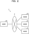
- FIG. 2 illustrates a configuration of the parallel processing system according to the example.
- the parallel processing system 1 according to the example includes a plurality of nodes 10.
- the plurality of nodes 10 are coupled to a network 2.
- Each node 10 performs communication for barrier synchronization with the node 10 connected in the binary tree via the network 2.
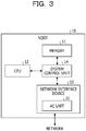
- FIG. 3 illustrates a configuration of the node 10.
- the node 10 includes a memory 11, a central processing unit (CPU) 12, a network interface device 13, and a system control unit 14.
- CPU central processing unit
- the memory 11 is a random-access memory (RAM) that stores a program and a result during execution of the program.
- the CPU 12 is a central processing unit for reading the program from the memory 11 and executing the program.
- the network interface device 13 communicates with another node 10 via the network 2.
- the network interface device 13 includes an AC unit 20.
- the AC unit 20 performs processing related to barrier synchronization.
- the system control unit 14 controls the entire node 10. For example, the system control unit 14 exchanges data and notifications between the memory 11 and the CPU 12 or between the CPU 12 and the network interface device 13.
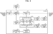
- FIG. 4 illustrates a functional configuration of the AC unit 20.
- the AC unit 20 includes a status storage unit 21, a reception unit 22, a transfer processing unit 23, a transmission unit 24, a threshold value storage unit 25, a determination unit 26, a time storage unit 27, a process storage unit 28, a threshold value setting unit 29, a time reading unit 30, and a process reading unit 31.
- the status storage unit 21 stores a bit vector.
- the reception unit 22 receives the completion notification and the identification number from the slave node 10 when the slave node 10 is present and receives the forcible suspension notification from the master node 10 when the master node 10 is present.
- the identification number is a number for identifying the node 10. Then, the reception unit 22 passes the received completion notification, the identification number, and the forcible suspension notification to the transfer processing unit 23.
- the transfer processing unit 23 When the transfer processing unit 23 is notified that the processing of the own node 10 is completed from the system control unit 14, the transfer processing unit 23 sets the bit corresponding to the own node 10 of the bit vector to 1, and transmits a completion notification and the identification number of the own node 10 to the master node 10 when the master node 10 is present. The transfer processing unit 23 transmits the completion notification and the identification number via the transmission unit 24.
- the transfer processing unit 23 When receiving the completion notification and the identification number from the reception unit 22, the transfer processing unit 23 sets the bit corresponding to the identification number of the bit vector to 1 and transfers the completion notification and the identification number to the master node 10 via the transmission unit 24 when the master node 10 is present.
- the transfer processing unit 23 When receiving the forcible suspension notification from the reception unit 22, the transfer processing unit 23 refers to the bit vector and instructs the system control unit 14 to suspend the processing when the own node 10 does not complete the processing. In addition, when receiving the forcible suspension notification from the reception unit 22, the transfer processing unit 23 refers to the bit vector and transfers the forcible suspension notification to the slave nodes 10 including the node 10 in which processing is not completed on the node 10 under management via the transmission unit 24. When transferring the forcible suspension notification, the transfer processing unit 23 designates the identification number of the slave node 10 of a transfer destination to the transmission unit 24.
- the transmission unit 24 transmits the completion notification received from the transfer processing unit 23 to the master node 10, and transmits the forcible suspension notification to the slave node 10 whose identification number is designated by the transfer processing unit 23. In addition, when the own node 10 is the root node 10, the transmission unit 24 transmits a forcible suspension notification to the slave node 10 based on an instruction from the determination unit 26.
- the threshold value storage unit 25 stores a threshold value m and a threshold value c (c is a positive integer).
- the threshold value m and the threshold value c are used by the determination unit 26.
- the determination unit 26 performs processing based on the mode designated by the program.
- the mode is 0, the determination unit 26 performs normal barrier synchronization. In other words, when all the bits of the bit vector are 1, the determination unit 26 completes synchronization between processes.
- the determination unit 26 performs AC parallelization. In other words, the determination unit 26 determines whether or not the number of 1 of the bit vector is the threshold value m or greater, determines that the synchronization condition is satisfied when the number of 1 of the bit vector is the threshold value m or greater, and forcibly suspends the processing in which processing is not completed.
- the determination unit 26 stores a current time in S.
- the time is a count number counted by a counter.
- S is a register, for example. Then, when the current time is (S + threshold value c) or longer, the determination unit 26 determines that the synchronization condition is satisfied, and forcibly suspends the process in which processing is not completed.
- the determination unit 26 stores, in the process storage unit 28, the number of the process operating in the node 10 instructed the forcible suspension in association with the number of times of the barrier synchronization. For example, the determination unit 26 specifies the process number from the bit vector by storing the process number notified from each node 10 in association with the node 10.
- the determination unit 26 collects data on AC parallelization.
- the determination unit 26 collects a time s at which one of the bits of the bit vector first is 1, a time m t at which the number of 1 of the bit vector is a threshold value m or greater, and a time e at which all bits of the bit vector are 1.
- the collected time s, time m t , and time e are retrieved by a program, for example.
- the determination unit 26 includes a first determination unit 26a, a second determination unit 26b, and a suspension instruction unit 26c.
- the first determination unit 26a determines whether or not the number of 1 of the bit vector is the threshold value m or greater, and when the number is the threshold value m or greater, the first determination unit 26a instructs the suspension instruction unit 26c to forcibly suspend the process in which processing is not completed.
- the second determination unit 26b stores the current time in S when one of the bits of the bit vector first is 1. Then, the second determination unit 26b determines whether or not the current time is (S + threshold value c) or longer, and when the current time is (S + threshold value c) or longer, the second determination unit 26b instructs the suspension instruction unit 26c to forcibly suspend the process in which processing is not completed.
- the suspension instruction unit 26c specifies the node 10 in which processing is not completed based on the bit vector. Then, when the specified node 10 includes the own node 10, the suspension instruction unit 26c instructs the system control unit 14 to forcibly suspend the processing.
- the suspension instruction unit 26c transmits a forcible suspension notification to the slave node 10 including the specified node 10 under management.
- the forcible suspension notification is processed by the transfer processing unit 23.
- the suspension instruction unit 26c transmits a forcible suspension notification via the transmission unit 24.
- the suspension instruction unit 26c may pass an estimated value of the processing result to the system control unit 14 and the instruction of the forcible suspension.
- the suspension instruction unit 26c may transmit the estimated value of the processing result and the instruction of the forcible suspension to the slave node 10 including the node 10 in which processing is not completed on the node 10 under management.
- the AC unit 20 stores past execution results and an average value of the execution results, and the suspension instruction unit 26c transmits the average value of the past execution results as the estimated value.
- the time storage unit 27 stores the time s, the time m t , and the time e collected by the determination unit 26.
- the process storage unit 28 stores the number of the process instructed to be forcibly suspended in association with the number of times of barrier synchronization.
- the threshold value setting unit 29 stores the threshold value m and the threshold value c on the threshold value storage unit 25.
- the threshold value m and the threshold value c are designated by a program.
- the threshold value setting unit 29 receives the threshold value m and the threshold value c designated by the program from the CPU 12 via the system control unit 14.
- the time reading unit 30 reads the time s, the time m t , and the time e from the time storage unit 27 and transmits these times to the CPU 12 via the system control unit 14.
- the process reading unit 31 reads the process number associated with the number of times of barrier synchronization from the process storage unit 28 and transmits the process number to the CPU 12 via the system control unit 14.
- FIG. 5 illustrates an example of a program designating the AC parallelization.
- a threshold value m and a threshold value c are designated by “set_AC_parameter (m, c)”.
- a location and mode of AC parallelization are designated by "start_AC_region (mode)” and “end_AC_region (mode)”.
- the time s, the time m t , and the time e are acquired by "get_AC_value (&S, &M, &E)".
- the threshold value m and the threshold value c are passed to the threshold value setting unit 29 of the root node 10 by "set_AC_parameter (m, c)”.
- the mode is passed to the determination unit 26 of the root node 10 by "start_AC_region (mode)", the bit vector of each node 10 is cleared to 0, and the time is reset.
- FIG. 6 is a flowchart illustrating a flow of processing for determining a threshold value m.
- the threshold value setting unit 29 sets n to m, instructs the node 10 to execute a process (Step S1) and acquires an accuracy A (Step S2). Then, the threshold value setting unit 29 receives an accuracy a c and an error t (Step S3).
- a c is a required accuracy and a c ⁇ A.
- t is an error with a c and is an error capable of securing required accuracy.
- the threshold value setting unit 29 sets n/2 to m, instructs the node 10 to execute the process (Step S4) and acquires an accuracy a (Step S5).
- the threshold value setting unit 29 determines whether or not the absolute value of the difference between a c and a is smaller than t (Step S6).
- the threshold value setting unit 29 sets a value obtained by adding y x to n/2 or a value obtained by subtracting y x from n/2 to m and instructs the node 10 to execute the process (Step S7).
- x is the number of times Step S7 is executed.
- y x is n/2 x+1 .
- y 2 is n/2 3 .
- the threshold value setting unit 29 sets a value obtained by adding y x to n/2 to m when a ⁇ a c , and sets a value obtained by subtracting y x from n/2 to m when a ⁇ a c . Then, the threshold value setting unit 29 returns to Step S5.
- the threshold value setting unit 29 determines m with a current value (Step S8).
- the AC unit 20 may optimize the AC parallelization function. Note that, the processing illustrated in FIG. 6 may be performed by an external device of the AC unit 20, and the AC unit 20 may receive the threshold value m determined by the external device.
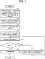
- FIG. 7 is a flowchart illustrating a flow of processing for determining a threshold value c.
- the threshold value setting unit 29 measures the number of clocks co when the first process is completed and the number of clocks c all when all processes are completed (Step S11) and acquires the accuracy A when all processes are completed (Step S12). Then, the threshold value setting unit 29 receives the accuracy a c and the error t (Step S13). Then, the threshold value setting unit 29 sets (c all - c 0 )/2 to c, instructs the node 10 to execute the process (Step S14) and acquires an accuracy a (Step S15).
- the threshold value setting unit 29 determines whether or not the absolute value of the difference between a c and a is smaller than t (Step S16). Then, when the absolute value of the difference between a c and a is smaller than t, the threshold value setting unit 29 sets a value obtained by adding y x to (c all - c 0 )/2 or a value obtained by subtracting y x from (c all - c 0 )/2 to c and instructs the node 10 to execute the process (Step S17).
- x is the number of times Step S17 is executed.
- y x is (c all - c 0 )/2 x+1 .
- y 1 is (c all - c 0 )/2 2 and y 2 is (c all - c 0 /2 3 .
- the threshold value setting unit 29 sets a value obtained by adding y x to (c all - c 0 )/2 to c when a ⁇ a c , and sets a value obtained by subtracting y x from (c all - c 0 )/2 to c when a ⁇ a c . Then, the threshold value setting unit 29 returns to Step S15.
- the threshold value setting unit 29 determines c with a current value (Step S18).
- the AC unit 20 may optimize the AC parallelization function. Note that, the processing illustrated in FIG. 7 may be performed by the external device of the AC unit 20, and the AC unit 20 may receive the threshold value c determined by the external device.
- FIG. 8 is a flowchart illustrating a flow of notification processing when the own node 10 completes the processing.
- the transfer processing unit 23 receives the completion notification of the processing from the system control unit 14 (Step S21)
- the transfer processing unit 23 sets the bit corresponding to the own node 10 of the bit vector to 1 (Step S22).
- the transfer processing unit 23 transmits a completion notification and the identification number of the own node 10 to the master node 10 (Step S23).
- the transfer processing unit 23 transmits the completion notification and the identification number of the own node 10 to the master node 10, the master node 10 may be notified that the processing of the own node 10 is completed.
- FIG. 9 is a flowchart illustrating a flow of the transfer processing when the completion notification is received from the slave node 10.
- the transfer processing unit 23 sets the bit corresponding to the identification number of the bit vector to 1 (Step S32). Then, when the master node 10 is present, the transfer processing unit 23 transmits a completion notification and an identification number to the master node 10 (Step S33).
- the root node 10 may specify the completion states of all the nodes 10.
- the determination unit 26 determines whether or not 1 is first set to one of the bits of the bit vector (Step S41), and when 1 is first set, the determination unit 26 sets the current time to S (Step S42).
- the determination unit 26 determines whether or not the number of 1 of the bit vector is m or greater (Step S43), and when the number of 1 of the bit vector is not m or greater, determines whether or not the current time is (S + c) or longer (Step S44). Then, when the current time is not (S + c) or longer, the determination unit 26 ends the AC parallelization processing.
- the determination unit 26 instructs the system control unit 14 to forcibly suspend the processing when the own node 10 does not complete the processing (Step S45). Then, the determination unit 26 transmits a forcible suspension notification to the lower node 10 not transmitted the completion notification along the binary tree (Step S46).
- the determination unit 26 when the number of 1 of the bit vector is m or greater or the current time is (S + c) or longer, the determination unit 26 forcibly suspends the processing for the node 10 in which processing is not completed. Therefore, the AC unit 20 may reduce the latency time in the barrier synchronization.
- FIG. 11 is a flowchart illustrating the flow of the transfer processing when the forcible suspension notification is received from the master node 10.
- the transfer processing unit 23 receives the forcible suspension notification from the master node 10 (Step S51), and when the own node 10 does not complete the processing, the transfer processing unit 23 instructs the system control unit 14 to forcibly suspend the processing (Step S52). Then, when the slave node 10 is present, the transfer processing unit 23 transmits a forcible suspension notification to the slave node 10 including the node 10 in which processing is not completed on the node 10 under management (Step S53).
- the transfer processing unit 23 transfers the forcible suspension notification received from the master node 10 to the slave nodes 10 including the node 10 in which processing is not completed on the node 10 under management, the node 10 in which processing is not completed may receive the forcible suspension notification.
- FIG. 12 illustrates an example of the hardware configuration of the network interface device 13.
- the network interface device 13 includes a microprocessor unit (MPU) 13a, a read-only memory (ROM) 13b, and a RAM 13c.
- MPU microprocessor unit
- ROM read-only memory
- RAM random access memory
- the MPU 13a is a processing device that reads and executes firmware (program) stored in the ROM 13b.
- the ROM 13b is a nonvolatile storage device that stores firmware.
- the RAM 13c is a storage device that stores data used by the firmware.
- the MPU 13a includes Pr 41, mr 42, cr 43, CNT 44, Sr 45, Mr 46, and Er 47.
- Pr 41 is a register for storing a bit vector.
- the status storage unit 21 is realized by Pr 41.
- mr 42 is a register for storing the threshold value m.
- cr 43 is a register for storing the threshold value c.
- the threshold value storage unit 25 is realized by mr 42 and cr 43.
- CNT 44 counts time.
- Sr 45 is a register for storing the time s.
- Mr 46 is a register for storing the time m t .
- Er 47 is a register for storing the time e.
- the time storage unit 27 is realized by Sr 45, Mr 46, and Er 47.
- each node 10 stores the bit vector. Then, when the mode is 1, the first determination unit 26a of the root node 10 compares the number of nodes 10 completed the processing with the threshold value m based on the bit vector, and determines whether or not the number of nodes 10 completed the processing is the threshold value m or greater. Then, when the number of nodes 10 completed the processing is the threshold value m or greater, the suspension instruction unit 26c specifies a node 10 in which processing is not completed based on the bit vector and instructs the specified node 10 to forcibly suspend. Therefore, the AC unit 20 may reduce the latency time in the barrier synchronization and improve the processing speed.
- the second determination unit 26b of the root node 10 detects a point of time at which one of the nodes 10 first completes the processing based on the bit vector, and determines whether or not an elapsed time from the detected point of time is the threshold value c or longer. Then, when the elapsed time since one of the nodes 10 first completes the processing is the threshold value c or longer, the suspension instruction unit 26c specifies the node 10 in which processing is not completed based on the bit vector, and instructs the specified node 10 to forcibly suspend. Therefore, the AC unit 20 may reduce the latency time in the barrier synchronization and improve the processing speed.
- the suspension instruction unit 26c instructs the system control unit 14 to forcibly suspend the process.
- the suspension instruction unit 26c refers to the bit vector and transmits a forcible suspension notification to the slave node 10 including the specified node 10 under the management. Then, in the slave node 10 receiving the forcible suspension notification, the transfer processing unit 23 refers to the bit vector and instructs the system control unit 14 to forcibly suspend the process when the own node 10 does not complete the processing.
- the transfer processing unit 23 refers to the bit vector and transfers the forcible suspension notification to the slave node 10 including the node 10 in which processing is not completed on the node 10 under management. Therefore, the suspension instruction unit 26c may instruct the node 10 in which processing is not completed to forcibly suspend.
- the AC unit 20 performs normal barrier synchronization when the mode is 0, performs AC parallelization when the mode is 1 and collects data for AC parallelization when the mode is 2. Therefore, the user may control the operation of the AC unit 20 by designating the mode by the program.
- the threshold value storage unit 25 stores the threshold value m and the threshold value c
- the threshold value setting unit 29 determines the optimum values of the threshold value m and the threshold value c and stores the optimum values in the threshold value storage unit 25.
- the first determination unit 26a compares the threshold value m stored in the threshold value storage unit 25 with the number of nodes 10 completed the processing
- the second determination unit 26b compares the threshold value c stored in the threshold value storage unit 25 with the elapsed time since one of the nodes 10 first completes the processing. Therefore, the AC unit 20 may optimize the AC parallelization function.
- the process storage unit 28 stores the forcible suspension process number in association with the number of times of barrier synchronization, and the process reading unit 31 reads and outputs the forcible suspension process number and the number of times from the process storage unit 28. Therefore, the AC unit 20 may provide information useful for analysis of the AC parallelization function.
- the AC unit 20 may provide the AC parallelization function without reducing the number of processes.
- the time storage unit 27 stores the time s, the time m t , and the time e
- the time reading unit 30 reads and outputs the time s, the time m t , and the time e from the time storage unit 27. Therefore, the AC unit 20 may provide information useful for analysis of the AC parallelization function.
- the case where both the first determination unit 26a and the second determination unit 26b operate when the mode is 1 is described, and the case where the mode is 1 may be subdivided.
- the node 10 may configure another tree structure for synchronous communication.
- all the nodes 10 include the threshold value storage unit 25, the determination unit 26, the time storage unit 27, the process storage unit 28, the threshold value setting unit 29, the time reading unit 30, and the process reading unit 31, and only the root node 10 may include these functional units.
Landscapes
- Engineering & Computer Science (AREA)
- Theoretical Computer Science (AREA)
- Software Systems (AREA)
- Physics & Mathematics (AREA)
- General Engineering & Computer Science (AREA)
- General Physics & Mathematics (AREA)
- Computer Networks & Wireless Communication (AREA)
- Signal Processing (AREA)
- Data Mining & Analysis (AREA)
- Databases & Information Systems (AREA)
- Multi Processors (AREA)
Abstract
Description
- The embodiment discussed herein is related to a barrier synchronization system, a parallel information processing apparatus, and a barrier synchronization program.
- In a parallel processing system in which a plurality of processing units are processed in parallel by a plurality of information processing apparatuses, there is barrier synchronization as a method of synchronizing the plurality of processing units. Here, the processing unit is a unit of using the information processing apparatus, and is, for example, a process.
-
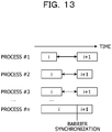
FIG. 13 is a diagram for describing barrier synchronization.FIG. 13 , theprocess # 1 to the process #n perform i-th processing in parallel, and the process #n completes the latest processing. As illustrated inFIG. 13 , in the barrier synchronization, the processes other than the latest process #n wait until the process #n completes the i-th processing, and when the process #n completes the i-th processing, theprocess # 1 to the process #n start (i+1)-th processing. -
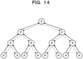
FIG. 14 is a diagram for describing communication between information processing apparatuses in the barrier synchronization. InFIG. 14 , a node denoted by P is an information processing apparatus on which a process for performing barrier synchronization operates. As illustrated inFIG. 14 , the information processing apparatus on which a process for performing barrier synchronization operates forms a binary tree. The information processing apparatus at a lowermost layer in the binary tree transmits a completion notification to a master information processing apparatus as illustrated by a solid line when itself completes the processing of the process. The information processing apparatuses at a second layer or higher transmit the completion notifications to the master information processing apparatus as illustrated by a solid line when the completion notifications of all the lower information processing apparatuses are available, and itself completes the processing of the process. - The information processing apparatus at an uppermost level receives the completion notification from all the lower information processing apparatuses, and itself completes the processing of the process, it is determined that all the information processing apparatuses are completed the processing of the process, and all the lower information processing apparatuses are notified that the processing is completed as illustrated by the broken line. The information processing apparatus notified that the processing is completed starts next processing.
- Note that, as a technique of related art, there is a synchronization processing circuit that performs synchronization processing of a portion or all of a plurality of processing means by using a plurality of nodes having tree structures. The node having the tree structure includes a plurality of leaf nodes located at the lowermost level and respectively corresponding to the plurality of processing means, a root node located at the uppermost level, and a plurality of internal nodes other than the root node and the leaf node. In this tree structure, not only a logical value is notified from a slave node to a master node, but also a logical value is notified from the master node to the slave node. Each internal node is provided with an internal node selection unit that selects whether to notify the master node of a logical value obtained by performing a logical operation on a logical value notified from the slave node of the internal node or to notify the master node of negation of the logical value notified from the master node.
- In the barrier synchronization, there is a difference in processing time between the processes, and thus there is a problem in that a process in which processing is first completed waits until processing of all the processes is completed.
- According to one aspect of the present invention, it is an object to reduce latency time and improve processing speed in barrier synchronization.
- According to an aspect of the embodiments, provided is a barrier synchronization system including: a plurality of information processing apparatuses configured to perform parallel processing while synchronizing by barrier synchronization, each information processing apparatus being configured to be one of a plurality of nodes in a tree structure and being associated with one or more of other nodes from among the plurality of nodes. In an example, each of the plurality of information processing apparatuses includes: a completion information storage; and a control circuit, wherein the completion information storage of a respective information processing apparatus is configured to store completion information including information relating to completion of processing of an own apparatus being the respective information processing apparatus, the completion information further including information relating to completion of processing of a lower information processing apparatus in case that the own apparatus is associated with the lower information processing apparatus, the lower information processing apparatus being one of the plurality of information processing apparatuses and being operated as a node lower than the own apparatus in the tree structure, wherein the control circuit of the respective information processing apparatus is configured to: when the respective information processing apparatus is configured to be operated as a root node located in a root in the tree structure, obtain a current status of parallel processing in the plurality of nodes by using the completion information storage; determine whether the obtained current status of the parallel processing amounts to a given condition; in response to a determination result indicating that the obtained current status of the parallel processing amounts to the given condition, specify an information processing apparatus from among the plurality of information processing apparatuses by using the completion information storage, the specified information processing apparatus being an apparatus that has not yet completed the processing; and instruct the specified information processing apparatus to forcibly suspend the processing before all of the plurality of information processing apparatuses have completed the processing.
- According to one aspect of the present invention, the latency time may be reduced and the processing speed may be improved in barrier synchronization.
-
-
FIG. 1 is a diagram for describing AC parallelization by a parallel processing system according to an example; -
FIG. 2 illustrates a configuration of the parallel processing system according to the example; -
FIG. 3 illustrates a configuration of a node; -
FIG. 4 illustrates a functional configuration of an AC unit; -
FIG. 5 illustrates an example of a program designating the AC parallelization; -
FIG. 6 is a flowchart illustrating a flow of processing for determining a threshold value m; -
FIG. 7 is a flowchart illustrating a flow of processing for determining a threshold value c; -
FIG. 8 is a flowchart illustrating a flow of notification processing when an own node completes processing; -
FIG. 9 is a flowchart illustrating a flow of transfer processing when a completion notification is received from a slave node; -
FIG. 10 is a flowchart illustrating a flow of processing by a determination unit when mode = 1; -
FIG. 11 is a flowchart illustrating a flow of transfer processing when a forcible suspension notification is received from a master node; -
FIG. 12 illustrates an example of a hardware configuration of a network interface device; -
FIG. 13 is a diagram for describing barrier synchronization; and -
FIG. 14 is a diagram for describing communication between information processing apparatuses in the barrier synchronization. - Hereinafter, an example of a barrier synchronization system, a method for barrier synchronization, and a parallel information processing apparatus disclosed in the present application will be described in detail with reference to the drawings. Note that, the example does not limit the techniques disclosed herein.
- First, approximate computing (AC) parallelization by a parallel processing system according to the example will be described.
FIG. 1 is a diagram for describing the AC parallelization by the parallel processing system according to the example. InFIG. 1 , anode 10 at a binary tree is an information processing apparatus that performs parallel processing. The number in thenode 10 is a number for identifying thenode 10. The number ofnodes 10 is 7. - The processing status of each
node 10 is represented by bit information of 1 bit. The bit information "1" indicates that processing is completed, and the bit information "0" indicates that processing is not completed. Eachnode 10 has a bit vector indicating a processing status in itself andnodes 10 lower than itself. Aroot node 10 has a bit vector holding bit information of allnodes 10. - In
FIG. 1 , each ofnode # 1,node # 2,node # 3, andnode # 4 has a bit vector of 1 bit. The bit vector of each ofnode # 1,node # 2, andnode # 3 is (1) indicating that itself completes the processing. The bit vector ofnode # 4 is (0) indicating that itself does not complete the processing. - Each of
node # 5 andnode # 6 has a bit vector of 3 bits. The bit vector ofnode # 5 is (1, 1, 1) indicating that itself,node # 1, andnode # 2 complete the processing. The bit vector ofnode # 6 is (1, 1, 0) indicating that itself andnode # 3 complete the processing, andnode # 4 does not complete the processing. -
Node # 7 has a bit vector of 7 bits. The bit vector ofnode # 7 is (1, 1, 1, 1, 1, 1, 0) indicating that itsown node 10,node # 5,node # 1,node # 2,node # 6, andnode # 3 complete the processing, andnode # 4 does not complete the processing. - When the processing is completed, the
node 10 at a lowermost layer in thebinary tree sets 1 to the bit vector and transmits a completion notification to themaster node 10 as illustrated by a solid line. InFIG. 1 , when the processing is completed,node # 1 andnode # 2 set 1 to the bit vector and transmit a completion notification tonode # 5. When the processing is completed,node # 3 andnode # 4 set 1 to the bit vector and transmit a completion notification tonode # 6. - When the processing is completed, the
node 10 at the second layer orhigher sets 1 to the corresponding bit vector and transmits a completion notification to themaster node 10 when themaster node 10 is present as illustrated by a solid-line arrow. In addition, when receiving the completion notification of one of thelower nodes 10 from theslave node 10, thenode 10 at the second layer or higher sets the corresponding bit vector to 1 and transfers the received completion notification to themaster node 10 when themaster node 10 is present. - In
FIG. 1 , when the processing is completed,node # 5 sets the bit corresponding tonode # 5 of the bit vector to 1 and transmits a completion notification tonode # 7. In addition, when receiving the completion notification fromnode # 1 ornode # 2,node # 5 sets the bit corresponding tonode # 1 ornode # 2 of the bit vector to 1 and transfers the received completion notification tonode # 7. - When the processing is completed,
node # 6 sets the bit corresponding tonode # 6 of the bit vector to 1 and transmits a completion notification tonode # 7. In addition, when receiving the completion notification fromnode # 3 ornode # 4,node # 6 sets the bit corresponding tonode # 3 ornode # 4 of the bit vector to 1 and transfers the received completion notification tonode # 7. - When the processing is completed,
node # 7 sets the bit corresponding tonode # 7 of the bit vector to 1. - When the number of 1 of the bit vector is m or greater, the
root node 10 transmits a forcible suspension (kill) notification to thenode 10 in which processing is not completed along the binary tree as illustrated by a broken-line arrow. In other words, when the number of 1 of the bit vector is m or greater, theroot node 10 transmits the forcible suspension notification to theslave node 10 including thenode 10 in which processing is not completed on thenode 10 under management. Here, thenode 10 under management is anode 10 included in a partial binary tree having theown node 10 as the root. Theslave node 10 receiving the forcible suspension notification suspends the processing when the processing is not completed and transmits the forcible suspension notification to theslave nodes 10 including thenode 10 in which processing is not completed on thenode 10 under management. - In
FIG. 1 , m is 5. Since the number of 1 of the bit vector is 5 or more,node # 7 transmits a forcible suspension notification to thenodes # 6 includingnode # 4 in which processing is not completed on thenode 10 under management.Node # 6 transfers the forcible suspension notification tonode # 4 includingnode # 4 in which processing is not completed on thenode 10 under management. - As described above, in an AC parallelization according to the example, when the number of 1 of the bit vector is m or greater, the
root node 10 transmits the forcible suspension notification to thenode 10 in which processing is not completed along the binary tree. Therefore, the parallel processing system according to the example may reduce the latency time and improve the processing speed in the barrier synchronization. - Next, a configuration of the parallel processing system according to the example is described below.
FIG. 2 illustrates a configuration of the parallel processing system according to the example. As illustrated inFIG. 2 , theparallel processing system 1 according to the example includes a plurality ofnodes 10. The plurality ofnodes 10 are coupled to anetwork 2. Eachnode 10 performs communication for barrier synchronization with thenode 10 connected in the binary tree via thenetwork 2. -
FIG. 3 illustrates a configuration of thenode 10. As illustrated inFIG. 3 , thenode 10 includes a memory 11, a central processing unit (CPU) 12, anetwork interface device 13, and asystem control unit 14. - The memory 11 is a random-access memory (RAM) that stores a program and a result during execution of the program. The CPU 12 is a central processing unit for reading the program from the memory 11 and executing the program.
- The
network interface device 13 communicates with anothernode 10 via thenetwork 2. Thenetwork interface device 13 includes anAC unit 20. TheAC unit 20 performs processing related to barrier synchronization. - The
system control unit 14 controls theentire node 10. For example, thesystem control unit 14 exchanges data and notifications between the memory 11 and the CPU 12 or between the CPU 12 and thenetwork interface device 13. -
FIG. 4 illustrates a functional configuration of theAC unit 20. As illustrated inFIG. 4 , theAC unit 20 includes astatus storage unit 21, a reception unit 22, atransfer processing unit 23, atransmission unit 24, a thresholdvalue storage unit 25, a determination unit 26, atime storage unit 27, a process storage unit 28, a thresholdvalue setting unit 29, atime reading unit 30, and aprocess reading unit 31. - The
status storage unit 21 stores a bit vector. The reception unit 22 receives the completion notification and the identification number from theslave node 10 when theslave node 10 is present and receives the forcible suspension notification from themaster node 10 when themaster node 10 is present. Here, the identification number is a number for identifying thenode 10. Then, the reception unit 22 passes the received completion notification, the identification number, and the forcible suspension notification to thetransfer processing unit 23. - When the
transfer processing unit 23 is notified that the processing of theown node 10 is completed from thesystem control unit 14, thetransfer processing unit 23 sets the bit corresponding to theown node 10 of the bit vector to 1, and transmits a completion notification and the identification number of theown node 10 to themaster node 10 when themaster node 10 is present. Thetransfer processing unit 23 transmits the completion notification and the identification number via thetransmission unit 24. - When receiving the completion notification and the identification number from the reception unit 22, the
transfer processing unit 23 sets the bit corresponding to the identification number of the bit vector to 1 and transfers the completion notification and the identification number to themaster node 10 via thetransmission unit 24 when themaster node 10 is present. - When receiving the forcible suspension notification from the reception unit 22, the
transfer processing unit 23 refers to the bit vector and instructs thesystem control unit 14 to suspend the processing when theown node 10 does not complete the processing. In addition, when receiving the forcible suspension notification from the reception unit 22, thetransfer processing unit 23 refers to the bit vector and transfers the forcible suspension notification to theslave nodes 10 including thenode 10 in which processing is not completed on thenode 10 under management via thetransmission unit 24. When transferring the forcible suspension notification, thetransfer processing unit 23 designates the identification number of theslave node 10 of a transfer destination to thetransmission unit 24. - The
transmission unit 24 transmits the completion notification received from thetransfer processing unit 23 to themaster node 10, and transmits the forcible suspension notification to theslave node 10 whose identification number is designated by thetransfer processing unit 23. In addition, when theown node 10 is theroot node 10, thetransmission unit 24 transmits a forcible suspension notification to theslave node 10 based on an instruction from the determination unit 26. - When the
own node 10 is theroot node 10, the thresholdvalue storage unit 25 stores a threshold value m and a threshold value c (c is a positive integer). The threshold value m and the threshold value c are used by the determination unit 26. - When the
own node 10 is theroot node 10, the determination unit 26 performs processing based on the mode designated by the program. When the mode is 0, the determination unit 26 performs normal barrier synchronization. In other words, when all the bits of the bit vector are 1, the determination unit 26 completes synchronization between processes. - When the mode is 1, the determination unit 26 performs AC parallelization. In other words, the determination unit 26 determines whether or not the number of 1 of the bit vector is the threshold value m or greater, determines that the synchronization condition is satisfied when the number of 1 of the bit vector is the threshold value m or greater, and forcibly suspends the processing in which processing is not completed.
- In addition, when one of the bits of the bit vector first is 1, the determination unit 26 stores a current time in S. Note that, here, the time is a count number counted by a counter. S is a register, for example. Then, when the current time is (S + threshold value c) or longer, the determination unit 26 determines that the synchronization condition is satisfied, and forcibly suspends the process in which processing is not completed.
- In addition, the determination unit 26 stores, in the process storage unit 28, the number of the process operating in the
node 10 instructed the forcible suspension in association with the number of times of the barrier synchronization. For example, the determination unit 26 specifies the process number from the bit vector by storing the process number notified from eachnode 10 in association with thenode 10. - When the mode is 2, the determination unit 26 collects data on AC parallelization. The determination unit 26 collects a time s at which one of the bits of the bit vector first is 1, a time mt at which the number of 1 of the bit vector is a threshold value m or greater, and a time e at which all bits of the bit vector are 1. The collected time s, time mt, and time e are retrieved by a program, for example.
- The determination unit 26 includes a
first determination unit 26a, asecond determination unit 26b, and asuspension instruction unit 26c. When the mode is 1, thefirst determination unit 26a determines whether or not the number of 1 of the bit vector is the threshold value m or greater, and when the number is the threshold value m or greater, thefirst determination unit 26a instructs thesuspension instruction unit 26c to forcibly suspend the process in which processing is not completed. - When the mode is 1, the
second determination unit 26b stores the current time in S when one of the bits of the bit vector first is 1. Then, thesecond determination unit 26b determines whether or not the current time is (S + threshold value c) or longer, and when the current time is (S + threshold value c) or longer, thesecond determination unit 26b instructs thesuspension instruction unit 26c to forcibly suspend the process in which processing is not completed. - When the mode is 1, and the
first determination unit 26a or thesecond determination unit 26b instructs to forcibly suspend the process in which processing is not completed, thesuspension instruction unit 26c specifies thenode 10 in which processing is not completed based on the bit vector. Then, when the specifiednode 10 includes theown node 10, thesuspension instruction unit 26c instructs thesystem control unit 14 to forcibly suspend the processing. - In addition, when the specified
node 10 includes anothernode 10, thesuspension instruction unit 26c transmits a forcible suspension notification to theslave node 10 including the specifiednode 10 under management. In theslave node 10 to which the forcible suspension notification is transmitted, the forcible suspension notification is processed by thetransfer processing unit 23. Thesuspension instruction unit 26c transmits a forcible suspension notification via thetransmission unit 24. - Note that, the
suspension instruction unit 26c may pass an estimated value of the processing result to thesystem control unit 14 and the instruction of the forcible suspension. In addition, thesuspension instruction unit 26c may transmit the estimated value of the processing result and the instruction of the forcible suspension to theslave node 10 including thenode 10 in which processing is not completed on thenode 10 under management. For example, theAC unit 20 stores past execution results and an average value of the execution results, and thesuspension instruction unit 26c transmits the average value of the past execution results as the estimated value. - When the
own node 10 is theroot node 10, thetime storage unit 27 stores the time s, the time mt, and the time e collected by the determination unit 26. When theown node 10 is theroot node 10, the process storage unit 28 stores the number of the process instructed to be forcibly suspended in association with the number of times of barrier synchronization. - When the
own node 10 is theroot node 10, the thresholdvalue setting unit 29 stores the threshold value m and the threshold value c on the thresholdvalue storage unit 25. The threshold value m and the threshold value c are designated by a program. The thresholdvalue setting unit 29 receives the threshold value m and the threshold value c designated by the program from the CPU 12 via thesystem control unit 14. - When the
own node 10 is theroot node 10, thetime reading unit 30 reads the time s, the time mt, and the time e from thetime storage unit 27 and transmits these times to the CPU 12 via thesystem control unit 14. When theown node 10 is theroot node 10, theprocess reading unit 31 reads the process number associated with the number of times of barrier synchronization from the process storage unit 28 and transmits the process number to the CPU 12 via thesystem control unit 14. -
FIG. 5 illustrates an example of a program designating the AC parallelization. As illustrated inFIG. 5 , a threshold value m and a threshold value c are designated by "set_AC_parameter (m, c)". In addition, a location and mode of AC parallelization are designated by "start_AC_region (mode)" and "end_AC_region (mode)". In addition, the time s, the time mt, and the time e are acquired by "get_AC_value (&S, &M, &E)". - In addition, the threshold value m and the threshold value c are passed to the threshold
value setting unit 29 of theroot node 10 by "set_AC_parameter (m, c)". In addition, the mode is passed to the determination unit 26 of theroot node 10 by "start_AC_region (mode)", the bit vector of eachnode 10 is cleared to 0, and the time is reset. - Note that, instead of designating the threshold value m and the threshold value c by the program, the threshold
value setting unit 29 may determine the threshold value m and the threshold value c.FIG. 6 is a flowchart illustrating a flow of processing for determining a threshold value m. - As illustrated in
FIG. 6 , the thresholdvalue setting unit 29 sets n to m, instructs thenode 10 to execute a process (Step S1) and acquires an accuracy A (Step S2). Then, the thresholdvalue setting unit 29 receives an accuracy ac and an error t (Step S3). Here, ac is a required accuracy and ac < A. In addition, t is an error with ac and is an error capable of securing required accuracy. Then, the thresholdvalue setting unit 29 sets n/2 to m, instructs thenode 10 to execute the process (Step S4) and acquires an accuracy a (Step S5). - Then, the threshold
value setting unit 29 determines whether or not the absolute value of the difference between ac and a is smaller than t (Step S6). When the absolute value is smaller, the thresholdvalue setting unit 29 sets a value obtained by adding yx to n/2 or a value obtained by subtracting yx from n/2 to m and instructs thenode 10 to execute the process (Step S7). Here, x is the number of times Step S7 is executed. In addition, yx is n/2x+1. For example, y1 is (n - m)/2 = n/22, and y2 is n/23. In addition, the thresholdvalue setting unit 29 sets a value obtained by adding yx to n/2 to m when a ≥ ac, and sets a value obtained by subtracting yx from n/2 to m when a < ac. Then, the thresholdvalue setting unit 29 returns to Step S5. - On the other hand, when the absolute value of the difference between ac and a is not smaller than t, the threshold
value setting unit 29 determines m with a current value (Step S8). - As described above, since the threshold
value setting unit 29 determines the threshold value m, theAC unit 20 may optimize the AC parallelization function. Note that, the processing illustrated inFIG. 6 may be performed by an external device of theAC unit 20, and theAC unit 20 may receive the threshold value m determined by the external device. -
FIG. 7 is a flowchart illustrating a flow of processing for determining a threshold value c. As illustrated inFIG. 7 , the thresholdvalue setting unit 29 measures the number of clocks co when the first process is completed and the number of clocks call when all processes are completed (Step S11) and acquires the accuracy A when all processes are completed (Step S12). Then, the thresholdvalue setting unit 29 receives the accuracy ac and the error t (Step S13). Then, the thresholdvalue setting unit 29 sets (call - c0)/2 to c, instructs thenode 10 to execute the process (Step S14) and acquires an accuracy a (Step S15). - Then, the threshold
value setting unit 29 determines whether or not the absolute value of the difference between ac and a is smaller than t (Step S16). Then, when the absolute value of the difference between ac and a is smaller than t, the thresholdvalue setting unit 29 sets a value obtained by adding yx to (call - c0)/2 or a value obtained by subtracting yx from (call - c0)/2 to c and instructs thenode 10 to execute the process (Step S17). Here, x is the number of times Step S17 is executed. In addition, yx is (call - c0)/2x+1. For example, y1 is (call - c0)/22 and y2 is (call - c0/23. In addition, the thresholdvalue setting unit 29 sets a value obtained by adding yx to (call - c0)/2 to c when a ≥ ac, and sets a value obtained by subtracting yx from (call - c0)/2 to c when a < ac. Then, the thresholdvalue setting unit 29 returns to Step S15. - On the other hand, when the absolute value of the difference between ac and a is not smaller than t, the threshold
value setting unit 29 determines c with a current value (Step S18). - As described above, since the threshold
value setting unit 29 determines the threshold value c, theAC unit 20 may optimize the AC parallelization function. Note that, the processing illustrated inFIG. 7 may be performed by the external device of theAC unit 20, and theAC unit 20 may receive the threshold value c determined by the external device. - Next, the processing flow of the
AC unit 20 will be described with reference toFIGs. 8 to 11 .FIG. 8 is a flowchart illustrating a flow of notification processing when theown node 10 completes the processing. As illustrated inFIG. 8 , when thetransfer processing unit 23 receives the completion notification of the processing from the system control unit 14 (Step S21), thetransfer processing unit 23 sets the bit corresponding to theown node 10 of the bit vector to 1 (Step S22). Then, when themaster node 10 is present, thetransfer processing unit 23 transmits a completion notification and the identification number of theown node 10 to the master node 10 (Step S23). - As described above, since the
transfer processing unit 23 transmits the completion notification and the identification number of theown node 10 to themaster node 10, themaster node 10 may be notified that the processing of theown node 10 is completed. -
FIG. 9 is a flowchart illustrating a flow of the transfer processing when the completion notification is received from theslave node 10. As illustrated inFIG. 9 , when receiving the completion notification and the identification number from the slave node 10 (Step S31), thetransfer processing unit 23 sets the bit corresponding to the identification number of the bit vector to 1 (Step S32). Then, when themaster node 10 is present, thetransfer processing unit 23 transmits a completion notification and an identification number to the master node 10 (Step S33). - As described above, since the
transfer processing unit 23 transfers the completion notification and the identification number received from theslave node 10 to themaster node 10, theroot node 10 may specify the completion states of all thenodes 10. -
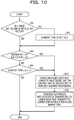
FIG. 10 is a flowchart illustrating the flow of the AC parallelization processing by the determination unit 26 when mode = 1. Note that, the AC parallelization processing inFIG. 10 is started when 1 is set to one of the bits of the bit vector and is periodically started. - As illustrated in
FIG. 10 , the determination unit 26 determines whether or not 1 is first set to one of the bits of the bit vector (Step S41), and when 1 is first set, the determination unit 26 sets the current time to S (Step S42). - Then, the determination unit 26 determines whether or not the number of 1 of the bit vector is m or greater (Step S43), and when the number of 1 of the bit vector is not m or greater, determines whether or not the current time is (S + c) or longer (Step S44). Then, when the current time is not (S + c) or longer, the determination unit 26 ends the AC parallelization processing.
- On the other hand, when the current time is (S + c) or longer or when the number of 1 of the bit vector is m or greater, the determination unit 26 instructs the
system control unit 14 to forcibly suspend the processing when theown node 10 does not complete the processing (Step S45). Then, the determination unit 26 transmits a forcible suspension notification to thelower node 10 not transmitted the completion notification along the binary tree (Step S46). - As described above, when the number of 1 of the bit vector is m or greater or the current time is (S + c) or longer, the determination unit 26 forcibly suspends the processing for the
node 10 in which processing is not completed. Therefore, theAC unit 20 may reduce the latency time in the barrier synchronization. -
FIG. 11 is a flowchart illustrating the flow of the transfer processing when the forcible suspension notification is received from themaster node 10. As illustrated inFIG. 11 , when thetransfer processing unit 23 receives the forcible suspension notification from the master node 10 (Step S51), and when theown node 10 does not complete the processing, thetransfer processing unit 23 instructs thesystem control unit 14 to forcibly suspend the processing (Step S52). Then, when theslave node 10 is present, thetransfer processing unit 23 transmits a forcible suspension notification to theslave node 10 including thenode 10 in which processing is not completed on thenode 10 under management (Step S53). - As described above, since the
transfer processing unit 23 transfers the forcible suspension notification received from themaster node 10 to theslave nodes 10 including thenode 10 in which processing is not completed on thenode 10 under management, thenode 10 in which processing is not completed may receive the forcible suspension notification. - Next, an example of a hardware configuration of the
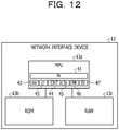
network interface device 13 will be described.FIG. 12 illustrates an example of the hardware configuration of thenetwork interface device 13. As illustrated inFIG. 12 , thenetwork interface device 13 includes a microprocessor unit (MPU) 13a, a read-only memory (ROM) 13b, and a RAM 13c. - The
MPU 13a is a processing device that reads and executes firmware (program) stored in theROM 13b. TheROM 13b is a nonvolatile storage device that stores firmware. The RAM 13c is a storage device that stores data used by the firmware. - The
MPU 13a includes Pr 41,mr 42,cr 43,CNT 44,Sr 45,Mr 46, andEr 47. Pr 41 is a register for storing a bit vector. Thestatus storage unit 21 is realized by Pr 41.mr 42 is a register for storing the thresholdvalue m. cr 43 is a register for storing the threshold value c. The thresholdvalue storage unit 25 is realized bymr 42 andcr 43.CNT 44 counts time.Sr 45 is a register for storing the time s.Mr 46 is a register for storing the time mt.Er 47 is a register for storing the time e. Thetime storage unit 27 is realized bySr 45,Mr 46, andEr 47. - As described above, in the example, each
node 10 stores the bit vector. Then, when the mode is 1, thefirst determination unit 26a of theroot node 10 compares the number ofnodes 10 completed the processing with the threshold value m based on the bit vector, and determines whether or not the number ofnodes 10 completed the processing is the threshold value m or greater. Then, when the number ofnodes 10 completed the processing is the threshold value m or greater, thesuspension instruction unit 26c specifies anode 10 in which processing is not completed based on the bit vector and instructs the specifiednode 10 to forcibly suspend. Therefore, theAC unit 20 may reduce the latency time in the barrier synchronization and improve the processing speed. - In addition, in the example, when the mode is 1, the
second determination unit 26b of theroot node 10 detects a point of time at which one of thenodes 10 first completes the processing based on the bit vector, and determines whether or not an elapsed time from the detected point of time is the threshold value c or longer. Then, when the elapsed time since one of thenodes 10 first completes the processing is the threshold value c or longer, thesuspension instruction unit 26c specifies thenode 10 in which processing is not completed based on the bit vector, and instructs the specifiednode 10 to forcibly suspend. Therefore, theAC unit 20 may reduce the latency time in the barrier synchronization and improve the processing speed. - In addition, in the example, when the specified
node 10 includes theown node 10, thesuspension instruction unit 26c instructs thesystem control unit 14 to forcibly suspend the process. In addition, when the specifiednode 10 includes anothernode 10, thesuspension instruction unit 26c refers to the bit vector and transmits a forcible suspension notification to theslave node 10 including the specifiednode 10 under the management. Then, in theslave node 10 receiving the forcible suspension notification, thetransfer processing unit 23 refers to the bit vector and instructs thesystem control unit 14 to forcibly suspend the process when theown node 10 does not complete the processing. In addition, when theslave node 10 is present, thetransfer processing unit 23 refers to the bit vector and transfers the forcible suspension notification to theslave node 10 including thenode 10 in which processing is not completed on thenode 10 under management. Therefore, thesuspension instruction unit 26c may instruct thenode 10 in which processing is not completed to forcibly suspend. - In addition, in the example, the
AC unit 20 performs normal barrier synchronization when the mode is 0, performs AC parallelization when the mode is 1 and collects data for AC parallelization when the mode is 2. Therefore, the user may control the operation of theAC unit 20 by designating the mode by the program. - In addition, in the example, the threshold
value storage unit 25 stores the threshold value m and the threshold value c, and the thresholdvalue setting unit 29 determines the optimum values of the threshold value m and the threshold value c and stores the optimum values in the thresholdvalue storage unit 25. Then, thefirst determination unit 26a compares the threshold value m stored in the thresholdvalue storage unit 25 with the number ofnodes 10 completed the processing, and thesecond determination unit 26b compares the threshold value c stored in the thresholdvalue storage unit 25 with the elapsed time since one of thenodes 10 first completes the processing. Therefore, theAC unit 20 may optimize the AC parallelization function. - In addition, in the example, the process storage unit 28 stores the forcible suspension process number in association with the number of times of barrier synchronization, and the
process reading unit 31 reads and outputs the forcible suspension process number and the number of times from the process storage unit 28. Therefore, theAC unit 20 may provide information useful for analysis of the AC parallelization function. - In addition, in the example, since the
suspension instruction unit 26c transmits the estimated value of the processing result of the process to the process instructed to be forcibly suspended, theAC unit 20 may provide the AC parallelization function without reducing the number of processes. - In addition, in the example, the
time storage unit 27 stores the time s, the time mt, and the time e, and thetime reading unit 30 reads and outputs the time s, the time mt, and the time e from thetime storage unit 27. Therefore, theAC unit 20 may provide information useful for analysis of the AC parallelization function. - Note that, in the example, the case where the process is allocated to the
node 10 is described, and instead of the process, another processing unit such as a thread may be allocated to thenode 10. - In addition, in the example, the case where both the
first determination unit 26a and thesecond determination unit 26b operate when the mode is 1 is described, and the case where the mode is 1 may be subdivided. In other words, it is also possible to provide three modes of a mode in which only thefirst determination unit 26a operates, a mode in which only thesecond determination unit 26b operates, and a mode in which both thefirst determination unit 26a and thesecond determination unit 26b operate. - In addition, in the example, the case where the binary tree is configured for synchronous communication is described, and the
node 10 may configure another tree structure for synchronous communication. - In addition, in the example, all the
nodes 10 include the thresholdvalue storage unit 25, the determination unit 26, thetime storage unit 27, the process storage unit 28, the thresholdvalue setting unit 29, thetime reading unit 30, and theprocess reading unit 31, and only theroot node 10 may include these functional units. - All examples and conditional language provided herein are intended for the pedagogical purposes of aiding the reader in understanding the invention and the concepts contributed by the inventor to further the art, and are not to be construed as limitations to such specifically recited examples and conditions, nor does the organization of such examples in the specification relate to a showing of the superiority and inferiority of the invention. Although one or more embodiments of the present invention have been described in detail, it should be understood that the various changes, substitutions, and alterations could be made hereto without departing from the spirit and scope of the invention.
- Japanese Laid-open Patent Publication No
. 2014-63278 -
- 1
- parallel processing system
- 2
- network
- 10
- node
- 11
- memory
- 12
- CPU
- 13
- network interface device
- 13a
- MPU
- 13b
- ROM
- 13c
- RAM
- 14
- system control unit
- 20
- AC unit
- 21
- status storage unit
- 22
- reception unit
- 23
- transfer processing unit
- 24
- transmission unit
- 25
- threshold value storage unit
- 26
- determination unit
- 26a
- first determination unit
- 26b
- second determination unit
- 26c
- suspension instruction unit
- 27
- time storage unit
- 28
- process storage unit
- 29
- threshold value setting unit
- 30
- time reading unit
- 31
- process reading unit
- 41
- Pr
- 42
- mr
- 43
- cr
- 44
- CNT
- 45
- Sr
- 46
- Mr
- 47
- Er
Claims (15)
- A barrier synchronization system comprising:a plurality of information processing apparatuses configured to perform parallel processing while synchronizing by barrier synchronization, each information processing apparatus being configured to be one of a plurality of nodes in a tree structure and being associated with one or more of other nodes from among the plurality of nodes,wherein each of the plurality of information processing apparatuses includes:a completion information storage; anda control circuit,wherein the completion information storage of a respective information processing apparatus is configured to store completion information including information relating to completion of processing of an own apparatus being the respective information processing apparatus, the completion information further including information relating to completion of processing of a lower information processing apparatus in case that the own apparatus is associated with the lower information processing apparatus, the lower information processing apparatus being one of the plurality of information processing apparatuses and being operated as a node lower than the own apparatus in the tree structure,wherein the control circuit of the respective information processing apparatus is configured to: when the respective information processing apparatus is configured to be operated as a root node located in a root in the tree structure,obtain a current status of parallel processing in the plurality of nodes by using the completion information storage;determine whether the obtained current status of the parallel processing amounts to a given condition;in response to a determination result indicating that the obtained current status of the parallel processing amounts to the given condition, specify an information processing apparatus from among the plurality of information processing apparatuses by using the completion information storage, the specified information processing apparatus being an apparatus that has not yet completed the processing; andinstruct the specified information processing apparatus to forcibly suspend the processing before all of the plurality of information processing apparatuses have completed the processing.
- The barrier synchronization system according to claim 1,
wherein the obtaining of the current status is configured to obtain a completion number by using the completion information storage, the completion number being a number corresponding to an amount of information processing apparatuses from among the plurality of information processing apparatuses, the information processing apparatuses having completed the processing,
wherein the determining is configured to determine, based on the completion information storage, whether a completion number is equal to or greater than a first threshold value, the first threshold value being a value less than an amount of the plurality of information processing apparatuses,
wherein the specifying is configured to, in response to a determination result indicating that the completion number is equal to or greater than the first threshold value, specify the information processing apparatus from among the plurality of information processing apparatuses by using the completion information storage. - The barrier synchronization system according to claim 1,
wherein the control circuit of the root node is configured to:detect, based on the completion information storage, a point of time at which one of the information processing apparatuses first completes the processing; anddetermine whether an elapsed time from a detected point of time is equal to or greater than a second threshold value,wherein the specifying of the information processing apparatus is performed in response to a determination result indicating that the elapsed time is equal to or greater than the second threshold value. - The barrier synchronization system according to claim 2, wherein
the control circuit of the root node is configured to:instruct the root node to forcibly suspend the processing in case that the specified information processing apparatus includes the root node; andtransmit a forcible suspension notification to other nodes in case that the specified information processing apparatus includes the other nodes, andthe control circuit of each of the other nodes is configured to: in response to receiving the forcible suspension notification,refer to the completion information storage of the own apparatus being the each of the other nodes;instruct the own apparatus to forcibly suspend the processing; andtransmit, when the own apparatus is associated with the lower information processing apparatus, a forcible suspension notification to the lower information processing apparatus. - The barrier synchronization system according to claim 2, wherein
the control circuit of the root node is configured to
perform a determination by using a value indicating a mode, the mode corresponding to a barrier synchronization operation to be performed in the barrier synchronization system. - The barrier synchronization system according to claim 2, wherein
the control circuit of the root node is configured to:adjust the first threshold value; andperform the determining by using the adjusted first threshold value. - The barrier synchronization system according to claim 2, wherein
the control circuit of the root node is configured to:store an identifier of a processing unit in association with the number of times of barrier synchronization, the processing unit being associated with the specified information processing apparatus instructed to forcibly suspend the processing; andread and output the stored identifier and the number of times. - The barrier synchronization system according to claim 2,
wherein the instructing of the forcibly suspending is configured to transmit an estimated result to the specified information processing apparatus, the estimated result corresponding to a result expected if the processing is completed, the transmitted estimated result being configured to instruct the specified information processing apparatus to execute next processing by using the estimated result. - The barrier synchronization system according to claim 2, wherein
the control circuit of the root node is configured to:store a plurality of times including a first time, a second time, and a third time, the first time being a time at which one of the information processing apparatuses has first completed the processing, the second time being a time at which the completion number has amounted to the first threshold value, the third time being a time at which all of the plurality of information processing apparatuses have completed the processing; andread and output any of the stored times. - A parallel information processing apparatus configured to perform parallel processing while synchronizing with other parallel information processing apparatuses in a barrier synchronization system by barrier synchronization, the parallel information processing apparatus and the other parallel information processing apparatuses being one of a plurality of parallel information processing apparatuses in the barrier synchronization system, each of the plurality of parallel information processing apparatuses being configured to be one of a plurality of nodes in a tree structure and being associated with one or more of other nodes from among the plurality of nodes, the parallel information processing apparatus comprising:a completion information storage; anda control circuit,wherein the completion information storage is configured to store completion information including information relating to completion of processing of an own apparatus being the parallel information processing apparatus, the completion information further including information relating to completion of processing of a lower information processing apparatus in case that the own apparatus is associated with the lower information processing apparatus, the lower information processing apparatus being one of the other parallel information processing apparatuses and being operated as a node lower than the own apparatus in the tree structure, andwherein the control circuit is configured to: when the parallel information processing apparatus is configured to be operated as a root node located in a root in the tree structure,obtain a current status of parallel processing in the plurality of nodes by using the completion information storage;determine whether the obtained current status of the parallel processing amounts to a given condition;in response to a determination result indicating that the obtained current status of the parallel processing amounts to the given condition, specify an information processing apparatus from among the plurality of parallel information processing apparatuses by using the completion information storage, the specified information processing apparatus being an apparatus that has not yet completed the processing; andinstruct the specified information processing apparatus to forcibly suspend the processing before all of the plurality of parallel information processing apparatuses have completed the processing.
- The parallel information processing apparatus according to claim 10,
wherein the obtaining of the current status is configured to obtain a completion number by using the completion information storage, the completion number being a number corresponding to an amount of information processing apparatuses from among the plurality of parallel information processing apparatuses, the information processing apparatuses having completed the processing,
wherein the determining is configured to determine, based on the completion information storage, whether a completion number is equal to or greater than a first threshold value, the first threshold value being a value less than an amount of the plurality of parallel information processing apparatuses,
wherein the specifying is configured to, in response to a determination result indicating that the completion number is equal to or greater than the first threshold value, specify the information processing apparatus from among the plurality of parallel information processing apparatuses by using the completion information storage. - The parallel information processing apparatus according to claim 10,
the control circuit is configured todetect, based on the completion information storage, a point of time at which one of the information processing apparatuses first completes the processing; anddetermine whether an elapsed time from a detected point of time is equal to or greater than a second threshold value,wherein the specifying of the information processing apparatus is performed in response to a determination result indicating that the elapsed time is equal to or greater than the second threshold value. - A barrier synchronization program which causes a processor of a parallel information processing apparatus to perform synchronization processing, the parallel information processing apparatus being one of a plurality of parallel information processing apparatuses in a barrier synchronization system, the parallel information processing apparatus being configured to perform parallel processing while synchronizing with other parallel information processing apparatuses by barrier synchronization, each of the plurality of parallel information processing apparatuses being configured to be one of a plurality of nodes in a tree structure and being associated with one or more of other nodes from among the plurality of nodes,
the synchronization processing comprising:when the information processing apparatus is configured to be operated as a root node located in a root in the tree structure,accessing a completion information storage, the completion information storage being configured to store completion information including information relating to completion of processing of an own apparatus being the parallel information processing apparatus, the completion information further including information relating to completion of processing of a lower information processing apparatus in case that the own apparatus is associated with the lower information processing apparatus, the lower information processing apparatus being one of the other parallel information processing apparatuses and being operated as a node lower than the own apparatus in the tree structure;obtaining a current status of parallel processing in the plurality of nodes by using the completion information storage;determining whether the obtained current status of the parallel processing amounts to a given condition;in response to a determination result indicating that the obtained current status of the parallel processing amounts to the given condition, specifying an information processing apparatus from among the plurality of parallel information processing apparatuses by using the completion information storage, the specified information processing apparatus being an apparatus that has not yet completed the processing; andinstructing the specified information processing apparatus to forcibly suspend the processing before all of the plurality of parallel information processing apparatuses have completed the processing. - The barrier synchronization program according to claim 13,
wherein the obtaining of the current status is configured to obtain a completion number by using the completion information storage, the completion number being a number corresponding to an amount of information processing apparatuses from among the plurality of parallel information processing apparatuses, the information processing apparatuses having completed the processing,
wherein the determining is configured to determine, based on the completion information storage, whether a completion number is equal to or greater than a first threshold value, the first threshold value being a value less than an amount of the plurality of parallel information processing apparatuses,
wherein the specifying is configured to, in response to a determination result indicating that the completion number is equal to or greater than the first threshold value, specify the information processing apparatus from among the plurality of parallel information processing apparatuses by using the completion information storage. - The barrier synchronization program according to claim 13,
the synchronization processing further comprising:detecting, based on the completion information storage, a point of time at which one of the information processing apparatuses first completes the processing; anddetermining whether an elapsed time from a detected point of time is equal to or greater than a second threshold value,wherein the specifying of the information processing apparatus is performed in response to a determination result indicating that the elapsed time is equal to or greater than the second threshold value.
Applications Claiming Priority (1)
| Application Number | Priority Date | Filing Date | Title |
|---|---|---|---|
| JP2019165751A JP2021043737A (en) | 2019-09-11 | 2019-09-11 | Barrier synchronization system, barrier synchronization method and parallel information processing device |
Publications (1)
| Publication Number | Publication Date |
|---|---|
| EP3792763A1 true EP3792763A1 (en) | 2021-03-17 |
Family
ID=72432714
Family Applications (1)
| Application Number | Title | Priority Date | Filing Date |
|---|---|---|---|
| EP20195026.8A Withdrawn EP3792763A1 (en) | 2019-09-11 | 2020-09-08 | Barrier synchronization system and parallel information processing apparatus |
Country Status (4)
| Country | Link |
|---|---|
| US (1) | US11487593B2 (en) |
| EP (1) | EP3792763A1 (en) |
| JP (1) | JP2021043737A (en) |
| CN (1) | CN112486693B (en) |
Families Citing this family (1)
| Publication number | Priority date | Publication date | Assignee | Title |
|---|---|---|---|---|
| CN112416053B (en) * | 2019-08-23 | 2023-11-17 | 北京希姆计算科技有限公司 | Synchronous signal generating circuit, chip and synchronous method and device of multi-core architecture |
Citations (4)
| Publication number | Priority date | Publication date | Assignee | Title |
|---|---|---|---|---|
| US20140007111A1 (en) * | 2012-06-28 | 2014-01-02 | Marek Targowski | Systems, methods, and computer program products for preemption of threads at a synchronization barrier |
| JP2014063278A (en) | 2012-09-20 | 2014-04-10 | Kyushu Univ | Synchronous processing circuit and synchronous processing method |
| JP2016062388A (en) * | 2014-09-19 | 2016-04-25 | 日本電気株式会社 | Information processing apparatus, information processing method, and program thereof |
| JP2017016250A (en) * | 2015-06-29 | 2017-01-19 | 日本電気株式会社 | Barrier synchronization device, barrier synchronization method, and program |
Family Cites Families (9)
| Publication number | Priority date | Publication date | Assignee | Title |
|---|---|---|---|---|
| JPH07302200A (en) * | 1994-04-28 | 1995-11-14 | Hewlett Packard Co <Hp> | Loading instruction method of computer provided with instruction forcing sequencing loading operation and sequencing storage |
| US7155588B1 (en) * | 2002-08-12 | 2006-12-26 | Cisco Technology, Inc. | Memory fence with background lock release |
| US7925791B2 (en) * | 2006-07-17 | 2011-04-12 | The Math Works, Inc. | Recoverable error detection for concurrent computing programs |
| US8095811B2 (en) * | 2008-05-29 | 2012-01-10 | International Business Machines Corporation | Reducing power consumption while synchronizing a plurality of compute nodes during execution of a parallel application |
| JP5664039B2 (en) * | 2010-09-08 | 2015-02-04 | 富士通株式会社 | Reduction operation device, processing device, and computer system |
| JP5549574B2 (en) * | 2010-12-17 | 2014-07-16 | 富士通株式会社 | Parallel computer system, synchronization device, and control method for parallel computer system |
| JP5994601B2 (en) * | 2012-11-27 | 2016-09-21 | 富士通株式会社 | Parallel computer, parallel computer control program, and parallel computer control method |
| US10733165B1 (en) * | 2015-07-06 | 2020-08-04 | Workiva Inc. | Distributed processing using a node hierarchy |
| US20170357705A1 (en) * | 2016-06-08 | 2017-12-14 | Knuedge Incorporated | Performing a synchronization operation on an electronic device |
-
2019
- 2019-09-11 JP JP2019165751A patent/JP2021043737A/en not_active Ceased
-
2020
- 2020-09-07 CN CN202010928271.9A patent/CN112486693B/en not_active Expired - Fee Related
- 2020-09-08 US US17/013,897 patent/US11487593B2/en active Active
- 2020-09-08 EP EP20195026.8A patent/EP3792763A1/en not_active Withdrawn
Patent Citations (4)
| Publication number | Priority date | Publication date | Assignee | Title |
|---|---|---|---|---|
| US20140007111A1 (en) * | 2012-06-28 | 2014-01-02 | Marek Targowski | Systems, methods, and computer program products for preemption of threads at a synchronization barrier |
| JP2014063278A (en) | 2012-09-20 | 2014-04-10 | Kyushu Univ | Synchronous processing circuit and synchronous processing method |
| JP2016062388A (en) * | 2014-09-19 | 2016-04-25 | 日本電気株式会社 | Information processing apparatus, information processing method, and program thereof |
| JP2017016250A (en) * | 2015-06-29 | 2017-01-19 | 日本電気株式会社 | Barrier synchronization device, barrier synchronization method, and program |
Also Published As
| Publication number | Publication date |
|---|---|
| US11487593B2 (en) | 2022-11-01 |
| CN112486693B (en) | 2023-07-07 |
| CN112486693A (en) | 2021-03-12 |
| JP2021043737A (en) | 2021-03-18 |
| US20210073049A1 (en) | 2021-03-11 |
Similar Documents
| Publication | Publication Date | Title |
|---|---|---|
| US20140115603A1 (en) | Method, apparatus, and system for scheduling processor core in multiprocessor core system | |
| CN105392188A (en) | Wireless communication apparatus, wireless communication system, and slot assignment method | |
| EP3792763A1 (en) | Barrier synchronization system and parallel information processing apparatus | |
| CN112511649B (en) | Multi-access edge calculation method and equipment | |
| US9955402B2 (en) | Information processing method, communications method, communications node, system, and computer product | |
| EP3792764A1 (en) | Barrier synchronization circuit, barrier synchronization method, and parallel information processing apparatus | |
| KR20110095201A (en) | A data processing apparatus, a control method thereof, and a storage medium storing a program | |
| US9910709B2 (en) | Allocation control method and apparatus | |
| US11212174B2 (en) | Network management device and network management method | |
| CN108306967A (en) | A kind of data processing method and terminal | |
| JP6442947B2 (en) | Information processing apparatus, information processing method, and program thereof | |
| JP2012089923A (en) | Congestion prevention ip repeater and method | |
| CN108541365B (en) | Apparatus and method for distribution of congestion information in switches | |
| US9336044B2 (en) | Parallel computer, and job information acquisition method for parallel computer | |
| US10244511B1 (en) | Systems and methods for selecting a node management device in a wireless network | |
| CN118132316A (en) | Jitter detection method, device and equipment for key task processes in operating system | |
| US12393883B2 (en) | Adaptively synchronizing learning of multiple learning models | |
| US11044116B2 (en) | Management device, communication system, management method, and computer readable medium | |
| US9003075B2 (en) | Transmission device and transmission method | |
| JP2018182688A (en) | INFORMATION PROCESSING APPARATUS, INFORMATION PROCESSING SYSTEM, AND CONTROL METHOD OF INFORMATION PROCESSING SYSTEM | |
| EP3276489A1 (en) | Parallel processing system | |
| JP5531811B2 (en) | Slot allocation method, management device, and edge router | |
| KR101983886B1 (en) | Communication method for receiving data of sonar signal | |
| CN107506175B (en) | Data flow graph congestion detection method based on execution efficiency gradient prediction | |
| KR20170055964A (en) | Method, device and system for deciding on a distribution path of a task |
Legal Events
| Date | Code | Title | Description |
|---|---|---|---|
| PUAI | Public reference made under article 153(3) epc to a published international application that has entered the european phase |
Free format text: ORIGINAL CODE: 0009012 |
|
| STAA | Information on the status of an ep patent application or granted ep patent |
Free format text: STATUS: THE APPLICATION HAS BEEN PUBLISHED |
|
| AK | Designated contracting states |
Kind code of ref document: A1 Designated state(s): AL AT BE BG CH CY CZ DE DK EE ES FI FR GB GR HR HU IE IS IT LI LT LU LV MC MK MT NL NO PL PT RO RS SE SI SK SM TR |
|
| AX | Request for extension of the european patent |
Extension state: BA ME |
|
| STAA | Information on the status of an ep patent application or granted ep patent |
Free format text: STATUS: REQUEST FOR EXAMINATION WAS MADE |
|
| 17P | Request for examination filed |
Effective date: 20210729 |
|
| RBV | Designated contracting states (corrected) |
Designated state(s): AL AT BE BG CH CY CZ DE DK EE ES FI FR GB GR HR HU IE IS IT LI LT LU LV MC MK MT NL NO PL PT RO RS SE SI SK SM TR |
|
| STAA | Information on the status of an ep patent application or granted ep patent |
Free format text: STATUS: THE APPLICATION HAS BEEN WITHDRAWN |
|
| 18W | Application withdrawn |
Effective date: 20231023 |