EP3792695A1 - Image forming apparatus and image forming method - Google Patents
Image forming apparatus and image forming method Download PDFInfo
- Publication number
- EP3792695A1 EP3792695A1 EP20183539.4A EP20183539A EP3792695A1 EP 3792695 A1 EP3792695 A1 EP 3792695A1 EP 20183539 A EP20183539 A EP 20183539A EP 3792695 A1 EP3792695 A1 EP 3792695A1
- Authority
- EP
- European Patent Office
- Prior art keywords
- image
- image forming
- reading
- unit
- power saving
- Prior art date
- Legal status (The legal status is an assumption and is not a legal conclusion. Google has not performed a legal analysis and makes no representation as to the accuracy of the status listed.)
- Withdrawn
Links
Images




Classifications
-
- G—PHYSICS
- G03—PHOTOGRAPHY; CINEMATOGRAPHY; ANALOGOUS TECHNIQUES USING WAVES OTHER THAN OPTICAL WAVES; ELECTROGRAPHY; HOLOGRAPHY
- G03G—ELECTROGRAPHY; ELECTROPHOTOGRAPHY; MAGNETOGRAPHY
- G03G15/00—Apparatus for electrographic processes using a charge pattern
- G03G15/50—Machine control of apparatus for electrographic processes using a charge pattern, e.g. regulating differents parts of the machine, multimode copiers, microprocessor control
- G03G15/5004—Power supply control, e.g. power-saving mode, automatic power turn-off
-
- G—PHYSICS
- G03—PHOTOGRAPHY; CINEMATOGRAPHY; ANALOGOUS TECHNIQUES USING WAVES OTHER THAN OPTICAL WAVES; ELECTROGRAPHY; HOLOGRAPHY
- G03G—ELECTROGRAPHY; ELECTROPHOTOGRAPHY; MAGNETOGRAPHY
- G03G15/00—Apparatus for electrographic processes using a charge pattern
- G03G15/20—Apparatus for electrographic processes using a charge pattern for fixing, e.g. by using heat
- G03G15/2003—Apparatus for electrographic processes using a charge pattern for fixing, e.g. by using heat using heat
- G03G15/2014—Apparatus for electrographic processes using a charge pattern for fixing, e.g. by using heat using heat using contact heat
- G03G15/2039—Apparatus for electrographic processes using a charge pattern for fixing, e.g. by using heat using heat using contact heat with means for controlling the fixing temperature
- G03G15/205—Apparatus for electrographic processes using a charge pattern for fixing, e.g. by using heat using heat using contact heat with means for controlling the fixing temperature specially for the mode of operation, e.g. standby, warming-up, error
-
- G—PHYSICS
- G03—PHOTOGRAPHY; CINEMATOGRAPHY; ANALOGOUS TECHNIQUES USING WAVES OTHER THAN OPTICAL WAVES; ELECTROGRAPHY; HOLOGRAPHY
- G03G—ELECTROGRAPHY; ELECTROPHOTOGRAPHY; MAGNETOGRAPHY
- G03G15/00—Apparatus for electrographic processes using a charge pattern
- G03G15/50—Machine control of apparatus for electrographic processes using a charge pattern, e.g. regulating differents parts of the machine, multimode copiers, microprocessor control
- G03G15/5025—Machine control of apparatus for electrographic processes using a charge pattern, e.g. regulating differents parts of the machine, multimode copiers, microprocessor control by measuring the original characteristics, e.g. contrast, density
-
- G—PHYSICS
- G03—PHOTOGRAPHY; CINEMATOGRAPHY; ANALOGOUS TECHNIQUES USING WAVES OTHER THAN OPTICAL WAVES; ELECTROGRAPHY; HOLOGRAPHY
- G03G—ELECTROGRAPHY; ELECTROPHOTOGRAPHY; MAGNETOGRAPHY
- G03G15/00—Apparatus for electrographic processes using a charge pattern
- G03G15/50—Machine control of apparatus for electrographic processes using a charge pattern, e.g. regulating differents parts of the machine, multimode copiers, microprocessor control
- G03G15/5075—Remote control machines, e.g. by a host
- G03G15/5087—Remote control machines, e.g. by a host for receiving image data
-
- G—PHYSICS
- G06—COMPUTING OR CALCULATING; COUNTING
- G06F—ELECTRIC DIGITAL DATA PROCESSING
- G06F1/00—Details not covered by groups G06F3/00 - G06F13/00 and G06F21/00
- G06F1/26—Power supply means, e.g. regulation thereof
- G06F1/32—Means for saving power
- G06F1/3203—Power management, i.e. event-based initiation of a power-saving mode
- G06F1/3234—Power saving characterised by the action undertaken
- G06F1/325—Power saving in peripheral device
- G06F1/3284—Power saving in printer
-
- G—PHYSICS
- G06—COMPUTING OR CALCULATING; COUNTING
- G06F—ELECTRIC DIGITAL DATA PROCESSING
- G06F3/00—Input arrangements for transferring data to be processed into a form capable of being handled by the computer; Output arrangements for transferring data from processing unit to output unit, e.g. interface arrangements
- G06F3/12—Digital output to print unit, e.g. line printer, chain printer
- G06F3/1201—Dedicated interfaces to print systems
- G06F3/1202—Dedicated interfaces to print systems specifically adapted to achieve a particular effect
- G06F3/1218—Reducing or saving of used resources, e.g. avoiding waste of consumables or improving usage of hardware resources
- G06F3/1221—Reducing or saving of used resources, e.g. avoiding waste of consumables or improving usage of hardware resources with regard to power consumption
-
- G—PHYSICS
- G06—COMPUTING OR CALCULATING; COUNTING
- G06F—ELECTRIC DIGITAL DATA PROCESSING
- G06F3/00—Input arrangements for transferring data to be processed into a form capable of being handled by the computer; Output arrangements for transferring data from processing unit to output unit, e.g. interface arrangements
- G06F3/12—Digital output to print unit, e.g. line printer, chain printer
- G06F3/1201—Dedicated interfaces to print systems
- G06F3/1223—Dedicated interfaces to print systems specifically adapted to use a particular technique
- G06F3/1229—Printer resources management or printer maintenance, e.g. device status, power levels
-
- H—ELECTRICITY
- H04—ELECTRIC COMMUNICATION TECHNIQUE
- H04N—PICTORIAL COMMUNICATION, e.g. TELEVISION
- H04N1/00—Scanning, transmission or reproduction of documents or the like, e.g. facsimile transmission; Details thereof
- H04N1/00885—Power supply means, e.g. arrangements for the control of power supply to the apparatus or components thereof
- H04N1/00888—Control thereof
- H04N1/00891—Switching on or off, e.g. for saving power when not in use
-
- H—ELECTRICITY
- H04—ELECTRIC COMMUNICATION TECHNIQUE
- H04N—PICTORIAL COMMUNICATION, e.g. TELEVISION
- H04N1/00—Scanning, transmission or reproduction of documents or the like, e.g. facsimile transmission; Details thereof
- H04N1/00885—Power supply means, e.g. arrangements for the control of power supply to the apparatus or components thereof
- H04N1/00888—Control thereof
- H04N1/00896—Control thereof using a low-power mode, e.g. standby
-
- G—PHYSICS
- G06—COMPUTING OR CALCULATING; COUNTING
- G06F—ELECTRIC DIGITAL DATA PROCESSING
- G06F3/00—Input arrangements for transferring data to be processed into a form capable of being handled by the computer; Output arrangements for transferring data from processing unit to output unit, e.g. interface arrangements
- G06F3/12—Digital output to print unit, e.g. line printer, chain printer
- G06F3/1201—Dedicated interfaces to print systems
- G06F3/1223—Dedicated interfaces to print systems specifically adapted to use a particular technique
- G06F3/1237—Print job management
- G06F3/1259—Print job monitoring, e.g. job status
-
- G—PHYSICS
- G06—COMPUTING OR CALCULATING; COUNTING
- G06V—IMAGE OR VIDEO RECOGNITION OR UNDERSTANDING
- G06V30/00—Character recognition; Recognising digital ink; Document-oriented image-based pattern recognition
- G06V30/10—Character recognition
-
- Y—GENERAL TAGGING OF NEW TECHNOLOGICAL DEVELOPMENTS; GENERAL TAGGING OF CROSS-SECTIONAL TECHNOLOGIES SPANNING OVER SEVERAL SECTIONS OF THE IPC; TECHNICAL SUBJECTS COVERED BY FORMER USPC CROSS-REFERENCE ART COLLECTIONS [XRACs] AND DIGESTS
- Y02—TECHNOLOGIES OR APPLICATIONS FOR MITIGATION OR ADAPTATION AGAINST CLIMATE CHANGE
- Y02D—CLIMATE CHANGE MITIGATION TECHNOLOGIES IN INFORMATION AND COMMUNICATION TECHNOLOGIES [ICT], I.E. INFORMATION AND COMMUNICATION TECHNOLOGIES AIMING AT THE REDUCTION OF THEIR OWN ENERGY USE
- Y02D10/00—Energy efficient computing, e.g. low power processors, power management or thermal management
Definitions
- Embodiments described herein relate generally to an image forming apparatus and an image forming method.
- Some image forming apparatuses can operate in a power saving mode in which a fixing device or the like is not warmed in order to realize energy saving.
- Such an image forming apparatus starts measuring the time to shift to the power saving mode after image formation. Then, the mode of the image forming apparatus is shifted to a power saving mode at a timing when a predetermined time passes.
- OCR optical character recognition
- an image forming apparatus having an optical character recognition (OCR) function stops measurement of the time to shift to the power saving mode even when executing an OCR process (document reading) in which image formation is not performed. Therefore, the time to shift to the power saving mode may be long, and energy may be wasted.
- OCR optical character recognition
- an image forming apparatus includes an image former, a fixer, a reader, and a controller.
- the image former is configured to form a visible image on a sheet.
- the fixer is configured to fix the visible image on the sheet.
- the reader is configured to read an image.
- the controller is configured to start measuring a time in response to determining no execution of a printing process; continue measuring the time during execution of a reading process that includes no execution of the printing process; and shift the image forming apparatus to a power saving mode in which power consumption is suppressed in response to determining that the measured time is greater than a predetermined set time.
- the controller may be further configured to not shift the image forming apparatus to the power saving mode until the reading process is completed.
- the reading process may be an optical character recognition (OCR) process.
- OCR optical character recognition
- the reading process is a read image saving process.
- the printing process includes forming the visible image on the sheet by at least the image former and the fixer.
- a predetermined power less than a power required for the fixer to fix the visible image on the sheet is supplied to the fixer in the power saving mode.
- no power is supplied to the fixer in the power saving mode.
- the present invention further relates to an image forming method comprising.
- the method comprising the following steps:
- the method may further comprise not shifting the image forming apparatus to the power saving mode until the reading process is completed.
- the method may further comprise stopping measuring the time in response to determining execution of the printing process.
- the reading process is an optical character recognition (OCR) process.
- OCR optical character recognition
- FIG. 1 is an external view showing an example of the overall configuration of an image forming apparatus 100 according to an embodiment.
- the image forming apparatus 100 is, for example, a multifunction peripheral.
- the image forming apparatus 100 includes a display 110, a control panel 120, a printer unit 130, a sheet accommodating unit 140, and an image reading unit 200.
- the image forming apparatus 100 forms an image on a sheet using a developer such as toner.
- the sheet is, for example, paper or label paper.
- the sheet may be any material as long as the image forming apparatus 100 can form an image on its surface.
- the display 110 is an image display device such as a liquid crystal display or an organic electro luminescence (EL) display.
- the display 110 displays various types of information regarding the image forming apparatus 100.
- the control panel 120 has a plurality of buttons.
- the control panel 120 receives an operation from a user.
- the control panel 120 outputs a signal corresponding to the operation performed by the user to a control unit of the image forming apparatus 100.
- the display 110 and the control panel 120 may be configured as an integral touch panel.
- the printer unit 130 forms an image on a sheet based on image information generated by the image reading unit 200 or image information received via a communication path.
- the printer unit 130 includes an image forming unit 160, a fixing unit 170, and the like, which will be described later.
- the printer unit 130 forms an image using a developer such as toner, for example.
- the sheet on which the image is formed may be a sheet accommodated in a sheet accommodating unit 140 or may be a manually inserted sheet.
- the sheet accommodating unit 140 accommodates a sheet used for image formation in the printer unit 130.
- the image reading unit 200 reads image information to be read as brightness and darkness of light.
- the image reading unit 200 records the read image information.
- the recorded image information may be transmitted to another information processing apparatus via a network.
- the recorded image information may form an image on a sheet by the printer unit 130.
- FIG. 2 is a view showing an example of a functional configuration of the image forming apparatus 100 according to the embodiment.
- the image forming apparatus 100 includes an image reading unit (or an image reader) 200, a control panel 120, a communication unit 150, an image forming unit (or an image former) 160, a fixing unit (or a fixer) 170, a storage unit 180, and a control unit (or a controller) 190.
- the communication unit 150 includes a communication interface for connecting the own device to an external device.
- the communication unit 150 communicates with an external device via wireless or wired communication, and outputs the received information to the control unit 190.
- the communication unit 150 receives, for example, a print job.
- the print job may include image information.
- the control unit 190 is configured using a processor such as a CPU or a memory.
- the control unit 190 operates by a processor executing a program.
- the control unit 190 controls the operation of each functional unit included in the image forming apparatus 100.
- the control unit 190 controls, for example, the power supplied to the fixing unit 170.
- the power supplied to the fixing unit 170 is, for example, power supplied to a halogen lamp.
- the control unit 190 executes, for example, an optical character recognition (OCR) process.
- OCR optical character recognition
- the control unit 190 controls, for example, the operation of the reading control unit 24.
- the image forming unit 160 and the fixing unit 170 operate according to the control of the control unit 190.
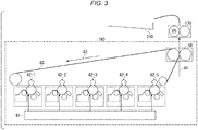
- FIG. 3 is a view showing an example of the configuration of the image forming unit 160 and the fixing unit 170 according to the embodiment.
- the image forming unit 160 operates, for example, as follows.
- An exposure unit 61 of the image forming unit 160 forms an electrostatic latent image on a photosensitive drum based on image information to be an object of image formation.
- a developing device of the image forming unit 160 forms a visible image (toner image) by attaching a developer to the electrostatic latent image.
- Primary transfer units 62-1 to 62-5 of the image forming unit 160 transfer the formed visible image to an image carrier (intermediate transfer member) 63.
- the rotation direction of the image carrier is a direction indicated by an arrow 92.
- the visible image formed on the image carrier is conveyed to a secondary transfer unit 68 by rotation of the image carrier.
- the secondary transfer unit 68 of the image forming unit 160 transfers the visible image formed on the image carrier onto a sheet conveyed in a direction of an arrow 91.
- the fixing unit 170 fixes the transferred visible image on the sheet.
- the fixing unit 170 includes, for example, a heat roller having a heat source therein, a pressure roller for pressing a sheet against the heat roller, and the like.
- Such a fixing unit 170 fixes the visible image on the sheet, for example, by the following operation. Power is supplied to a halogen lamp and the halogen lamp emits heat. The heat roller is heated by the heat emitted from the halogen lamp. The sheet is pressed against the heat roller by the pressure roller. The visible image is fixed on the sheet by applying pressure by pressing and heat of the heat roller to the visible image.
- the sheet on which the visible image is fixed by the fixing unit 170 is conveyed to a paper discharge unit 210 and discharged from the inside of the image forming apparatus 100 to the outside.
- the storage unit 180 is configured using a storage device such as a magnetic hard disk drive or a semiconductor storage device.
- the storage unit 180 stores various values used in the process of the control unit 190.
- FIG. 4 is a flowchart showing an example of a flow of an OCR process in the embodiment.
- the image reading unit 200 acquires image information to be read (ACT 101).
- the control unit 190 executes a character conversion process (ACT 102).
- the character conversion process is a process of detecting a character string in an object to be read based on image information. Specifically, the following process is executed in the character conversion process. First, a character area is determined based on the acquired image information. Next, an image of each character in the determined area is extracted. Next, the character indicated by the extracted image is determined. Next, the determination result is output as character string information (text information) for all the extracted characters. After ACT 102, the detection result (text information) is output to the display 110 (ACT 103). The detection result does not necessarily have to be output to the display 110, and the detection result may be transmitted to a predetermined external device via the communication unit 150, or the detection result may be stored in the storage unit 180.
- FIG. 5 is a flowchart showing an example of a flow of a process executed by the image forming apparatus 100 according to the embodiment.
- the control unit 190 determines whether or not the printing is being executed (ACT 201).
- the printing is a process that involves execution of a fixing process for fixing a visible image on a sheet.
- the printing is, for example, a process of forming an image on a sheet by the image forming unit 160 and the fixing unit 170.
- the control unit 190 starts measurement of an elapsed time until the mode is shifted to the power saving mode (ACT 202).
- the power saving mode shift time is an operation mode in which power consumption is suppressed. More specifically, for example, the power saving mode is an operation mode operated in a state where the power supplied to the fixing unit 170 is less than a predetermined power (hereinafter, referred to as "reference power").
- the power saving mode may be, for example, an operation mode in which power is not supplied to the fixing unit 170.
- the reference power is the power required for the fixing process.
- the fixing process is a process in which the fixing unit 170 fixes a visible image on a sheet. The temperature of the heat roller of the fixing unit 170 to which the reference power is supplied is raised to a temperature that allows the visible image to be fixed on the sheet.
- the control unit 190 executes a power saving timer process (ACT 203) .
- FIG. 6 is a flowchart showing an example of the flow of the power saving timer process in the embodiment.
- the control unit 190 determines whether or not the printing is being executed (ACT 301). When the printing is not being executed (ACT 301: NO), the control unit 190 determines whether or not the reading process without the execution of the printing is being executed (ACT 302).
- the reading process without the execution of the printing is referred to as non-printing reading.
- the reading process is a process in which an image is read from the image reading unit 200.
- the non-printing reading is, for example, a process itself in which the image reading unit 200 reads an image.
- the non-printing reading is, for example, an OCR process.
- the non-printing reading is, for example, a read image saving process of saving image data of a read original document as a file.
- ACT 302 when the non-printing reading is being executed (ACT 302: YES), the control unit 190 continues the measurement of the power saving mode shift time (ACT 303). Next, the control unit 190 determines whether or not the power saving mode shift time elapses a predetermined set time set in advance (ACT 304). When the power saving mode shift time elapses the set time (ACT 304: YES), the control unit 190 shifts the operation mode of the image forming apparatus 100 to the power saving mode (ACT 305). Next, the control unit 190 resets the power saving mode shift time (ACT 306).
- the control unit 190 stops the measurement of the power saving mode shift time (ACT 307).
- the control unit 190 resets the power saving mode shift time (ACT 308). After ACT 308, the process returns to ACT 201.
- the image forming apparatus 100 configured in this manner includes the control unit 190 that continues the measurement of the power saving mode shift time even during execution of the reading process without the execution of the printing such as the OCR process. Therefore, it is possible to suppress an increase in the time to shift to the power saving mode by execution of the reading process without the execution of the printing, and it is possible to eliminate the waste of energy.
- the power saving timer process is not necessarily limited to the flow shown in FIG. 6 .
- a process of shifting the mode to a power saving mode may be executed after the non-printing reading is completed.
- FIG. 7 the specific process flow in this case is described in FIG. 7 .
- FIG. 7 is a flowchart showing an example of a flow of a power saving timer process in a modification example.
- the same process as in FIG. 6 will be omitted by using the same reference numerals.
- the process of ACT 301 is executed in the same manner as in FIG. 6 .
- the control unit 190 determines whether or not the power saving mode shift time elapses the set time (ACT 304a). When the power saving mode shift time does not elapse the set time (ACT 304a: NO), the process returns to ACT 301.
- the control unit 190 determines whether or not the non-printing reading is being executed (ACT 302a). When the non-printing reading is being executed (ACT 302a: YES), the control unit 190 continues the measurement of the power saving mode shift time (ACT 303a).
- the process returns to ACT 301.
- ACT 302a when the non-printing reading is not being executed in ACT 302a (ACT 302a: NO), the process of ACT 305 is executed. After the execution of the process of ACT 305, the process of ACT 306 is executed.
- ACT 301 when the printing is being executed (ACT 301: YES), the process of ACT 307 is executed. After the process of ACT 307, the same process as in FIG. 6 is executed.
- a method of fixing a visible image on a sheet by heating through a film-like member may be applied.
- the image reading unit 200 is an example of the reading unit.
- the condition shown in FIG. 5 that the printing is not being executed is an example of a predetermined condition regarding the shift of the operation mode of the own device.
- the control panel 120 is an example of an input unit.
- the waste of energy can be eliminated.
- All or part of various functions of the image forming apparatus 100 may be realized using hardware such as an application specific integrated circuit (ASIC), a programmable logic device (PLD), or a field programmable gate array (FPGA) .
- the program may be recorded on a computer readable recording medium.
- the compute readable recording medium may be a portable medium such as a flexible disk, a magneto-optical disk, a ROM, or a CD-ROM, or a storage device such as a hard disk built in a computer system.
- the program may be transmitted via an electric communication line.
Landscapes
- Engineering & Computer Science (AREA)
- Theoretical Computer Science (AREA)
- Physics & Mathematics (AREA)
- General Physics & Mathematics (AREA)
- General Engineering & Computer Science (AREA)
- Human Computer Interaction (AREA)
- Microelectronics & Electronic Packaging (AREA)
- Multimedia (AREA)
- Signal Processing (AREA)
- Control Or Security For Electrophotography (AREA)
- Accessory Devices And Overall Control Thereof (AREA)
Abstract
According to one embodiment, an image forming apparatus includes an image forming unit, a fixing unit, a reading unit, and a control unit. The image forming unit forms a visible image on a sheet. The fixing unit executes a fixing process of fixing the visible image on the sheet. The reading unit executes a reading process of reading an image. The control unit starts measurement of time until shift to a power saving mode, and shifts the operation mode to the power saving mode in which power consumption is suppressed when the measured time passes a predetermined set time. The control unit stops the measurement of the time during execution of printing, which is a process involving execution of the fixing process, and continues the measurement of the time during execution of the reading process without execution of the printing.
Description
- Embodiments described herein relate generally to an image forming apparatus and an image forming method.
- Some image forming apparatuses can operate in a power saving mode in which a fixing device or the like is not warmed in order to realize energy saving. Such an image forming apparatus starts measuring the time to shift to the power saving mode after image formation. Then, the mode of the image forming apparatus is shifted to a power saving mode at a timing when a predetermined time passes. However, an image forming apparatus having an optical character recognition (OCR) function stops measurement of the time to shift to the power saving mode even when executing an OCR process (document reading) in which image formation is not performed. Therefore, the time to shift to the power saving mode may be long, and energy may be wasted.
-
-
FIG. 1 is an external view showing an example of the overall configuration of an image forming apparatus according to an embodiment; -
FIG. 2 is a view showing an example of a functional configuration of the image forming apparatus; -
FIG. 3 is a view showing an example of the configuration of an image forming unit and a fixing unit; -
FIG. 4 is a flowchart showing an example of a flow of an OCR process; -
FIG. 5 is a flowchart showing an example of a flow of a process executed by the image forming apparatus; -
FIG. 6 is a flowchart showing an example of a flow of a power saving timer process; and -
FIG. 7 is a flowchart showing an example of the flow of the power saving timer process according to a modification example. - In general, according to one embodiment, an image forming apparatus includes an image former, a fixer, a reader, and a controller. The image former is configured to form a visible image on a sheet. The fixer is configured to fix the visible image on the sheet. The reader is configured to read an image. The controller is configured to start measuring a time in response to determining no execution of a printing process; continue measuring the time during execution of a reading process that includes no execution of the printing process; and shift the image forming apparatus to a power saving mode in which power consumption is suppressed in response to determining that the measured time is greater than a predetermined set time.
- The controller may be further configured to not shift the image forming apparatus to the power saving mode until the reading process is completed.
- The reading process may be an optical character recognition (OCR) process.
- Preferably, the reading process is a read image saving process.
- Preferably, the printing process includes forming the visible image on the sheet by at least the image former and the fixer.
- Preferably, a predetermined power less than a power required for the fixer to fix the visible image on the sheet is supplied to the fixer in the power saving mode.
- Preferably, no power is supplied to the fixer in the power saving mode.
- The present invention further relates to an image forming method comprising.
- The method comprising the following steps:
- determining whether to execute a printing process that includes fix a visible image on a sheet;
- determining whether to execute a reading process that includes reading an image;
- starting measuring a time in response to determining no execution of the printing process;
- continuing measuring the time during execution of the reading process; and
- shifting an image forming apparatus to a power saving mode in which power consumption is suppressed in response to determining that the measured time is greater than a predetermined set time.
- The method may further comprise not shifting the image forming apparatus to the power saving mode until the reading process is completed.
- The method may further comprise stopping measuring the time in response to determining execution of the printing process.
- According to the method, the reading process is an optical character recognition (OCR) process.
- Hereinafter, an image forming apparatus and an image forming method according to the embodiments will be described with reference to the drawings.
-
FIG. 1 is an external view showing an example of the overall configuration of animage forming apparatus 100 according to an embodiment. Theimage forming apparatus 100 is, for example, a multifunction peripheral. Theimage forming apparatus 100 includes adisplay 110, acontrol panel 120, aprinter unit 130, asheet accommodating unit 140, and animage reading unit 200. Theimage forming apparatus 100 forms an image on a sheet using a developer such as toner. The sheet is, for example, paper or label paper. The sheet may be any material as long as theimage forming apparatus 100 can form an image on its surface. - The
display 110 is an image display device such as a liquid crystal display or an organic electro luminescence (EL) display. Thedisplay 110 displays various types of information regarding theimage forming apparatus 100. - The
control panel 120 has a plurality of buttons. Thecontrol panel 120 receives an operation from a user. Thecontrol panel 120 outputs a signal corresponding to the operation performed by the user to a control unit of theimage forming apparatus 100. Thedisplay 110 and thecontrol panel 120 may be configured as an integral touch panel. - The
printer unit 130 forms an image on a sheet based on image information generated by theimage reading unit 200 or image information received via a communication path. Theprinter unit 130 includes animage forming unit 160, afixing unit 170, and the like, which will be described later. Theprinter unit 130 forms an image using a developer such as toner, for example. The sheet on which the image is formed may be a sheet accommodated in asheet accommodating unit 140 or may be a manually inserted sheet. - The
sheet accommodating unit 140 accommodates a sheet used for image formation in theprinter unit 130. - The
image reading unit 200 reads image information to be read as brightness and darkness of light. Theimage reading unit 200 records the read image information. The recorded image information may be transmitted to another information processing apparatus via a network. The recorded image information may form an image on a sheet by theprinter unit 130. -
FIG. 2 is a view showing an example of a functional configuration of theimage forming apparatus 100 according to the embodiment. Theimage forming apparatus 100 includes an image reading unit (or an image reader) 200, acontrol panel 120, acommunication unit 150, an image forming unit (or an image former) 160, a fixing unit (or a fixer) 170, astorage unit 180, and a control unit (or a controller) 190. - The
communication unit 150 includes a communication interface for connecting the own device to an external device. Thecommunication unit 150 communicates with an external device via wireless or wired communication, and outputs the received information to thecontrol unit 190. Thecommunication unit 150 receives, for example, a print job. The print job may include image information. - The
control unit 190 is configured using a processor such as a CPU or a memory. Thecontrol unit 190 operates by a processor executing a program. Thecontrol unit 190 controls the operation of each functional unit included in theimage forming apparatus 100. Thecontrol unit 190 controls, for example, the power supplied to the fixingunit 170. The power supplied to the fixingunit 170 is, for example, power supplied to a halogen lamp. Thecontrol unit 190 executes, for example, an optical character recognition (OCR) process. Thecontrol unit 190 controls, for example, the operation of the reading control unit 24. - The
image forming unit 160 and the fixingunit 170 operate according to the control of thecontrol unit 190. -
FIG. 3 is a view showing an example of the configuration of theimage forming unit 160 and the fixingunit 170 according to the embodiment. Theimage forming unit 160 operates, for example, as follows. An exposure unit 61 of theimage forming unit 160 forms an electrostatic latent image on a photosensitive drum based on image information to be an object of image formation. A developing device of theimage forming unit 160 forms a visible image (toner image) by attaching a developer to the electrostatic latent image. Primary transfer units 62-1 to 62-5 of theimage forming unit 160 transfer the formed visible image to an image carrier (intermediate transfer member) 63. The rotation direction of the image carrier is a direction indicated by an arrow 92. Therefore, the visible image formed on the image carrier is conveyed to a secondary transfer unit 68 by rotation of the image carrier. The secondary transfer unit 68 of theimage forming unit 160 transfers the visible image formed on the image carrier onto a sheet conveyed in a direction of an arrow 91. - The fixing
unit 170 fixes the transferred visible image on the sheet. The fixingunit 170 includes, for example, a heat roller having a heat source therein, a pressure roller for pressing a sheet against the heat roller, and the like. Such a fixingunit 170 fixes the visible image on the sheet, for example, by the following operation. Power is supplied to a halogen lamp and the halogen lamp emits heat. The heat roller is heated by the heat emitted from the halogen lamp. The sheet is pressed against the heat roller by the pressure roller. The visible image is fixed on the sheet by applying pressure by pressing and heat of the heat roller to the visible image. The sheet on which the visible image is fixed by the fixingunit 170 is conveyed to a paper discharge unit 210 and discharged from the inside of theimage forming apparatus 100 to the outside. - The
storage unit 180 is configured using a storage device such as a magnetic hard disk drive or a semiconductor storage device. Thestorage unit 180 stores various values used in the process of thecontrol unit 190. -
FIG. 4 is a flowchart showing an example of a flow of an OCR process in the embodiment. - The
image reading unit 200 acquires image information to be read (ACT 101). Next, thecontrol unit 190 executes a character conversion process (ACT 102). The character conversion process is a process of detecting a character string in an object to be read based on image information. Specifically, the following process is executed in the character conversion process. First, a character area is determined based on the acquired image information. Next, an image of each character in the determined area is extracted. Next, the character indicated by the extracted image is determined. Next, the determination result is output as character string information (text information) for all the extracted characters. After ACT 102, the detection result (text information) is output to the display 110 (ACT 103). The detection result does not necessarily have to be output to thedisplay 110, and the detection result may be transmitted to a predetermined external device via thecommunication unit 150, or the detection result may be stored in thestorage unit 180. -
FIG. 5 is a flowchart showing an example of a flow of a process executed by theimage forming apparatus 100 according to the embodiment. - At a predetermined timing, the
control unit 190 determines whether or not the printing is being executed (ACT 201). The printing is a process that involves execution of a fixing process for fixing a visible image on a sheet. The printing is, for example, a process of forming an image on a sheet by theimage forming unit 160 and the fixingunit 170. - When the printing is being executed (ACT 201: YES), the process ends. On the other hand, when the printing is not being executed (ACT 201: NO), the
control unit 190 starts measurement of an elapsed time until the mode is shifted to the power saving mode (ACT 202). Hereinafter, the elapsed time until the mode is shifted to the power saving mode is referred to as the power saving mode shift time. The power saving mode is an operation mode in which power consumption is suppressed. More specifically, for example, the power saving mode is an operation mode operated in a state where the power supplied to the fixingunit 170 is less than a predetermined power (hereinafter, referred to as "reference power"). The power saving mode may be, for example, an operation mode in which power is not supplied to the fixingunit 170. The reference power is the power required for the fixing process. The fixing process is a process in which thefixing unit 170 fixes a visible image on a sheet. The temperature of the heat roller of the fixingunit 170 to which the reference power is supplied is raised to a temperature that allows the visible image to be fixed on the sheet. After ACT 202, thecontrol unit 190 executes a power saving timer process (ACT 203) . -
FIG. 6 is a flowchart showing an example of the flow of the power saving timer process in the embodiment. Thecontrol unit 190 determines whether or not the printing is being executed (ACT 301). When the printing is not being executed (ACT 301: NO), thecontrol unit 190 determines whether or not the reading process without the execution of the printing is being executed (ACT 302). Hereinafter, the reading process without the execution of the printing is referred to as non-printing reading. The reading process is a process in which an image is read from theimage reading unit 200. The non-printing reading is, for example, a process itself in which theimage reading unit 200 reads an image. The non-printing reading is, for example, an OCR process. The non-printing reading is, for example, a read image saving process of saving image data of a read original document as a file. - In ACT 302, when the non-printing reading is being executed (ACT 302: YES), the
control unit 190 continues the measurement of the power saving mode shift time (ACT 303). Next, thecontrol unit 190 determines whether or not the power saving mode shift time elapses a predetermined set time set in advance (ACT 304). When the power saving mode shift time elapses the set time (ACT 304: YES), thecontrol unit 190 shifts the operation mode of theimage forming apparatus 100 to the power saving mode (ACT 305). Next, thecontrol unit 190 resets the power saving mode shift time (ACT 306). - On the other hand, when the printing is being executed in ACT 301 (ACT 301: YES), the
control unit 190 stops the measurement of the power saving mode shift time (ACT 307). Next, thecontrol unit 190 resets the power saving mode shift time (ACT 308). After ACT 308, the process returns to ACT 201. - When the
control panel 120 is operated, the processes of ACT 301 and ACT 302 are determined as NO. - The
image forming apparatus 100 configured in this manner includes thecontrol unit 190 that continues the measurement of the power saving mode shift time even during execution of the reading process without the execution of the printing such as the OCR process. Therefore, it is possible to suppress an increase in the time to shift to the power saving mode by execution of the reading process without the execution of the printing, and it is possible to eliminate the waste of energy. - The power saving timer process is not necessarily limited to the flow shown in
FIG. 6 . When the set time elapses during the execution of the non-printing reading, a process of shifting the mode to a power saving mode may be executed after the non-printing reading is completed. Hereinafter, the specific process flow in this case is described inFIG. 7 . -
FIG. 7 is a flowchart showing an example of a flow of a power saving timer process in a modification example. Hereinafter, the same process as inFIG. 6 will be omitted by using the same reference numerals. - The process of ACT 301 is executed in the same manner as in
FIG. 6 . When the printing is not executed (ACT 301: NO), thecontrol unit 190 determines whether or not the power saving mode shift time elapses the set time (ACT 304a). When the power saving mode shift time does not elapse the set time (ACT 304a: NO), the process returns to ACT 301. On the other hand, when the power saving mode shift time elapses the set time (ACT 304a: YES), thecontrol unit 190 determines whether or not the non-printing reading is being executed (ACT 302a). When the non-printing reading is being executed (ACT 302a: YES), thecontrol unit 190 continues the measurement of the power saving mode shift time (ACT 303a). Next, the process returns to ACT 301. On the other hand, when the non-printing reading is not being executed in ACT 302a (ACT 302a: NO), the process of ACT 305 is executed. After the execution of the process of ACT 305, the process of ACT 306 is executed. On the other hand, in ACT 301, when the printing is being executed (ACT 301: YES), the process of ACT 307 is executed. After the process of ACT 307, the same process as inFIG. 6 is executed. - In the fixing
unit 170 of the embodiment, a method of fixing a visible image on a sheet by heating through a film-like member may be applied. - The
image reading unit 200 is an example of the reading unit. In addition, the condition shown inFIG. 5 that the printing is not being executed is an example of a predetermined condition regarding the shift of the operation mode of the own device. Thecontrol panel 120 is an example of an input unit. - According to at least one embodiment described above, by providing the
control unit 190, the waste of energy can be eliminated. - All or part of various functions of the
image forming apparatus 100 may be realized using hardware such as an application specific integrated circuit (ASIC), a programmable logic device (PLD), or a field programmable gate array (FPGA) . The program may be recorded on a computer readable recording medium. For example, the compute readable recording medium may be a portable medium such as a flexible disk, a magneto-optical disk, a ROM, or a CD-ROM, or a storage device such as a hard disk built in a computer system. The program may be transmitted via an electric communication line. - While certain embodiments have been described, these embodiments have been presented by way of example only, and are not intended to limit the scope of the inventions. Indeed, the novel embodiments described herein may be embodied in a variety of other forms; furthermore, various omissions, substitutions and changes in the form of the embodiments described herein may be made without departing from the scope of the inventions. The accompanying claims and their equivalents are intended to cover such forms or modifications as would fall within the scope of the inventions.
Claims (11)
- An image forming apparatus comprising:an image former configured to form a visible image on a sheet;a fixer configured to fix the visible image on the sheet;an image reader configured to read an image; anda controller configured to:start measuring a time in response to determining no execution of a printing process;continue measuring the time during execution of a reading process; andshift the image forming apparatus to a power saving mode in which power consumption is suppressed in response to determining that the measured time is greater than a predetermined set time.
- The apparatus according to claim 1, wherein
the controller is further configured to not shift the image forming apparatus to the power saving mode until the reading process is completed. - The apparatus according to claim 1 or 2, wherein
the reading process is an optical character recognition (OCR) process. - The apparatus according to any one of claims 1 to 3, wherein
the reading process is a read image saving process. - The apparatus according to any one of claims 1 to 4, wherein
the printing process includes forming the visible image on the sheet by at least the image former and the fixer. - The apparatus according to any one of claims 1 to 5, wherein
a predetermined power less than a power required for the fixer to fix the visible image on the sheet is supplied to the fixer in the power saving mode. - The apparatus according to any one of claims 1 to 6, wherein
no power is supplied to the fixer in the power saving mode. - An image forming method comprising:determining whether to execute a printing process that includes fix a visible image on a sheet;determining whether to execute a reading process that includes reading an image;starting measuring a time in response to determining no execution of the printing process;continuing measuring the time during execution of the reading process; andshifting an image forming apparatus to a power saving mode in which power consumption is suppressed in response to determining that the measured time is greater than a predetermined set time.
- The method of claim 8, further comprising:
not shifting the image forming apparatus to the power saving mode until the reading process is completed. - The method of claim 8 or 9, further comprising:
stopping measuring the time in response to determining execution of the printing process. - The method of any one of claims 8 to 10, wherein the reading process is an optical character recognition (OCR) process.
Applications Claiming Priority (1)
| Application Number | Priority Date | Filing Date | Title |
|---|---|---|---|
| US16/567,491 US10908855B1 (en) | 2019-09-11 | 2019-09-11 | Image forming apparatus with power saving mode |
Publications (1)
| Publication Number | Publication Date |
|---|---|
| EP3792695A1 true EP3792695A1 (en) | 2021-03-17 |
Family
ID=71579509
Family Applications (1)
| Application Number | Title | Priority Date | Filing Date |
|---|---|---|---|
| EP20183539.4A Withdrawn EP3792695A1 (en) | 2019-09-11 | 2020-07-01 | Image forming apparatus and image forming method |
Country Status (3)
| Country | Link |
|---|---|
| US (1) | US10908855B1 (en) |
| EP (1) | EP3792695A1 (en) |
| CN (1) | CN112485986B (en) |
Citations (6)
| Publication number | Priority date | Publication date | Assignee | Title |
|---|---|---|---|---|
| JPH07281553A (en) * | 1994-04-08 | 1995-10-27 | Sanyo Electric Co Ltd | Image forming device |
| JPH11184022A (en) * | 1997-12-18 | 1999-07-09 | Canon Inc | Image reading apparatus and electrophotographic image forming apparatus |
| JP2003162185A (en) * | 2001-11-28 | 2003-06-06 | Kyocera Mita Corp | Image forming device |
| JP2007114330A (en) * | 2005-10-19 | 2007-05-10 | Ricoh Co Ltd | Image forming apparatus |
| EP2434369A1 (en) * | 2010-09-22 | 2012-03-28 | Canon Kabushiki Kaisha | Image processing apparatus capable of shifting to power saving mode, control method for the image processing apparatus, and program |
| JP2016163205A (en) * | 2015-03-03 | 2016-09-05 | コニカミノルタ株式会社 | Image processing device and program |
Family Cites Families (12)
| Publication number | Priority date | Publication date | Assignee | Title |
|---|---|---|---|---|
| JP4475099B2 (en) * | 2004-11-04 | 2010-06-09 | 富士ゼロックス株式会社 | Image forming apparatus and operation screen display control program |
| JP4650162B2 (en) | 2005-08-25 | 2011-03-16 | 富士ゼロックス株式会社 | Printing apparatus, power saving mode transition time extension method, and program |
| JP5558925B2 (en) * | 2009-07-09 | 2014-07-23 | キヤノン株式会社 | Information processing apparatus, control method for information processing apparatus, and control program |
| JP5422512B2 (en) * | 2010-07-30 | 2014-02-19 | 京セラドキュメントソリューションズ株式会社 | Electric equipment and power supply control method |
| JP5746501B2 (en) * | 2010-12-20 | 2015-07-08 | キヤノン株式会社 | Printing apparatus and processing method thereof |
| JP5935481B2 (en) * | 2011-12-27 | 2016-06-15 | ブラザー工業株式会社 | Reader |
| US9007635B2 (en) * | 2012-06-18 | 2015-04-14 | Canon Kabushiki Kaisha | Image-forming apparatus communicating with an information-processing apparatus |
| JP6140994B2 (en) * | 2012-12-07 | 2017-06-07 | キヤノン株式会社 | Printing system, printing control apparatus, printing control apparatus control method, and program |
| JP6860279B2 (en) * | 2014-05-23 | 2021-04-14 | キヤノン株式会社 | Image forming apparatus and control method of image forming apparatus |
| JP6012690B2 (en) * | 2014-10-30 | 2016-10-25 | 京セラドキュメントソリューションズ株式会社 | Image forming apparatus |
| JP2018061167A (en) * | 2016-10-06 | 2018-04-12 | キヤノン株式会社 | Image processing apparatus, control method thereof, and program |
| JP6953211B2 (en) * | 2017-07-18 | 2021-10-27 | キヤノン株式会社 | Information processing device and control method of information processing device |
-
2019
- 2019-09-11 US US16/567,491 patent/US10908855B1/en not_active Expired - Fee Related
-
2020
- 2020-07-01 EP EP20183539.4A patent/EP3792695A1/en not_active Withdrawn
- 2020-07-21 CN CN202010706127.0A patent/CN112485986B/en active Active
Patent Citations (6)
| Publication number | Priority date | Publication date | Assignee | Title |
|---|---|---|---|---|
| JPH07281553A (en) * | 1994-04-08 | 1995-10-27 | Sanyo Electric Co Ltd | Image forming device |
| JPH11184022A (en) * | 1997-12-18 | 1999-07-09 | Canon Inc | Image reading apparatus and electrophotographic image forming apparatus |
| JP2003162185A (en) * | 2001-11-28 | 2003-06-06 | Kyocera Mita Corp | Image forming device |
| JP2007114330A (en) * | 2005-10-19 | 2007-05-10 | Ricoh Co Ltd | Image forming apparatus |
| EP2434369A1 (en) * | 2010-09-22 | 2012-03-28 | Canon Kabushiki Kaisha | Image processing apparatus capable of shifting to power saving mode, control method for the image processing apparatus, and program |
| JP2016163205A (en) * | 2015-03-03 | 2016-09-05 | コニカミノルタ株式会社 | Image processing device and program |
Also Published As
| Publication number | Publication date |
|---|---|
| CN112485986A (en) | 2021-03-12 |
| CN112485986B (en) | 2024-12-20 |
| US10908855B1 (en) | 2021-02-02 |
Similar Documents
| Publication | Publication Date | Title |
|---|---|---|
| US20250008039A1 (en) | Image forming apparatus and controlling method for the same | |
| US9164440B2 (en) | Image forming apparatus | |
| US10771651B2 (en) | Image forming apparatus and image correction method | |
| JP2014134589A (en) | Image forming apparatus | |
| US20140016154A1 (en) | Service providing apparatus, service providing system, service providing method, and non-transitory computer-readable medium | |
| JP5734322B2 (en) | Image forming apparatus | |
| EP4047419B1 (en) | Image forming apparatus and program | |
| KR20140148319A (en) | Printing apparatus, method of controlling the same and storage medium | |
| US10908855B1 (en) | Image forming apparatus with power saving mode | |
| JP2017026741A (en) | Image forming apparatus, control method, and control program | |
| CN105319923A (en) | Image forming apparatus with detachable fixing device and control method thereof | |
| US20180074446A1 (en) | Image forming apparatus | |
| JP6316158B2 (en) | Image forming apparatus | |
| US9625863B1 (en) | Image forming apparatus and control method comprising heating modes | |
| US11856167B2 (en) | Image forming apparatus capable of on-off control of operating key lamp according to anbient illuminance | |
| US10324401B1 (en) | Image forming apparatus, image recoloring apparatus and image forming method | |
| US9152074B1 (en) | Image forming apparatus and control method of image forming apparatus | |
| CN111638633B (en) | Image forming apparatus having a plurality of image forming units | |
| JP6265116B2 (en) | Image forming apparatus | |
| US20160077474A1 (en) | Image forming apparatus, which includes a fixing device capable of fixing erasable toner | |
| JP2025042411A (en) | Image forming device | |
| JP6676312B2 (en) | PRINTING DEVICE, PRINTING DEVICE CONTROL METHOD, AND PROGRAM | |
| JP2013052618A (en) | Printing apparatus, method of controlling the same, and program | |
| EP3115849A1 (en) | Select device for image forming apparatus, image forming system, and select method for image forming apparatus | |
| KR20050013854A (en) | Printing controlling method for printer |
Legal Events
| Date | Code | Title | Description |
|---|---|---|---|
| PUAI | Public reference made under article 153(3) epc to a published international application that has entered the european phase |
Free format text: ORIGINAL CODE: 0009012 |
|
| STAA | Information on the status of an ep patent application or granted ep patent |
Free format text: STATUS: THE APPLICATION HAS BEEN PUBLISHED |
|
| AK | Designated contracting states |
Kind code of ref document: A1 Designated state(s): AL AT BE BG CH CY CZ DE DK EE ES FI FR GB GR HR HU IE IS IT LI LT LU LV MC MK MT NL NO PL PT RO RS SE SI SK SM TR |
|
| AX | Request for extension of the european patent |
Extension state: BA ME |
|
| STAA | Information on the status of an ep patent application or granted ep patent |
Free format text: STATUS: THE APPLICATION IS DEEMED TO BE WITHDRAWN |
|
| 18D | Application deemed to be withdrawn |
Effective date: 20210918 |