EP3792524A1 - Compound harmonic gearbox configured for continuous output rotation - Google Patents
Compound harmonic gearbox configured for continuous output rotation Download PDFInfo
- Publication number
- EP3792524A1 EP3792524A1 EP19212912.0A EP19212912A EP3792524A1 EP 3792524 A1 EP3792524 A1 EP 3792524A1 EP 19212912 A EP19212912 A EP 19212912A EP 3792524 A1 EP3792524 A1 EP 3792524A1
- Authority
- EP
- European Patent Office
- Prior art keywords
- gear
- ground
- spline
- shaft
- gearbox
- Prior art date
- Legal status (The legal status is an assumption and is not a legal conclusion. Google has not performed a legal analysis and makes no representation as to the accuracy of the status listed.)
- Granted
Links
Images


Classifications
-
- F—MECHANICAL ENGINEERING; LIGHTING; HEATING; WEAPONS; BLASTING
- F16—ENGINEERING ELEMENTS AND UNITS; GENERAL MEASURES FOR PRODUCING AND MAINTAINING EFFECTIVE FUNCTIONING OF MACHINES OR INSTALLATIONS; THERMAL INSULATION IN GENERAL
- F16H—GEARING
- F16H49/00—Other gearings
- F16H49/001—Wave gearings, e.g. harmonic drive transmissions
-
- F—MECHANICAL ENGINEERING; LIGHTING; HEATING; WEAPONS; BLASTING
- F16—ENGINEERING ELEMENTS AND UNITS; GENERAL MEASURES FOR PRODUCING AND MAINTAINING EFFECTIVE FUNCTIONING OF MACHINES OR INSTALLATIONS; THERMAL INSULATION IN GENERAL
- F16H—GEARING
- F16H49/00—Other gearings
- F16H49/001—Wave gearings, e.g. harmonic drive transmissions
- F16H2049/003—Features of the flexsplines therefor
Definitions
- Exemplary embodiments pertain to the art of gearboxes and more specifically to a compound harmonic gearbox configured for continuous output rotation.
- Compound harmonic gearboxes enable achieving a high power density. Such gearboxes may be used in machinery requiring high torque output at low speeds. Such gearboxes may also be compact and lightweight.
- a compound harmonic gearbox comprising: a first ground gear and a second ground gear being interconnected about a stationary shaft to form a housing, wherein only the first ground gear includes gearbox mounting features; an output flange partially encased within the housing; a flex spline within the housing that drives the output flange; a wave generator within the housing that drives the flex spline; an input shaft with an input gear that drives the wave generator, the input shaft extending through the first ground gear, wherein the output flange is configured to rotate completely around the stationary shaft by rotating the input shaft.
- the input shaft extends through an input-shaft channel in one of a first axial end wall of the first ground gear and a first radial outer shell of the first ground gear.
- one or more input-shaft bearings are disposed in the input-shaft channel for rotational positioning of the input shaft.
- the input shaft extends axially through the first axial end wall and is radially offset from an axial center of the stationary shaft; and the input gear defines a first spur gear, and an axial end of the wave generator defines a second spur gear that meshes with the first spur gear.
- the input shaft extends radially through the first radial outer shell of the first ground gear; and the input gear defines a first bevel gear and an axial end of the wave generator defines a second bevel gear that meshes with the input gear.
- the gearbox includes a stationary-shaft bearing, wherein: a portion of the stationary shaft defines a stationary-shaft bearing inner race; a stationary-shaft bearing outer race is connected to the wave generator; and a stationary-shaft bearing rolling element is disposed therebetween.
- the gearbox includes a drive bearing including a drive bearing inner race connected to the wave generator, a drive bearing outer race connected to the flex spline, and a drive bearing rolling element therebetween.
- the drive bearing and the flex spline have a same axial span and are axially aligned with one another.
- first radial outer shell of the first ground gear is disposed against a first axial side of the output flange and a second radial outer shell of the second ground gear is disposed against a second axial side of the output flange, whereby the output flange is partially encased in the housing.
- the stationary shaft extends axially from a second axial end wall of the second ground gear and is secured to the first axial end wall of the first ground gear to thereby form the housing.
- the first axial end wall includes an opening that forms a keyway and the stationary shaft includes a key.
- the axial end of the stationary shaft includes a threaded tip configured to receive a nut to secure the first ground gear and the second ground gear to one another, thereby securing the housing at the output flange.
- the gearbox includes a plurality of support bearings respectively disposed on axially opposing ends of the flex spline.
- the flex spline includes a plurality of splines that are outer facing, including an output spline, a first ground spline on one side of the output spline and a second ground spline on another side of the output spline, so that the second ground spline is axially offset from the first ground spline, and the output spline is axially between the first ground spline and the second ground spline, whereby the flex spline is configured as a compound spline.
- the output flange includes output gear teeth that mesh with the output spline
- the first ground gear includes first ground gear teeth that mesh with the first ground spline
- the second ground gear includes second ground gear teeth that mesh with the second ground spline.
- first ground spline and the first ground gear teeth are configured to mesh to thereby form a first gear ratio
- the output spline and the output gear teeth are configured to mesh to thereby form a second gear ratio that differs from the first gear ratio to form a compound gear ratio
- the second ground spline and the second ground gear teeth are configured to mesh and form the first gear ratio.
- the second spur gear and the first ground gear teeth are axially positioned at axially opposing ends of the stationary-shaft bearing; and a first support bearing of the plurality of support bearings is positioned axially intermediate the second spur gear and the first ground gear teeth.
- gearbox mounting features are threaded-holes.
- a method of operating a compound harmonic gearbox comprising: rotating an input shaft that extends through one of a first axial end wall of a first ground gear or a first radial outer shell of the first ground gear, wherein the first ground gear is interconnected with a second ground gear about a stationary shaft to form a housing, and only the first ground gear includes gearbox mounting features; rotating an input gear by rotating the input shaft; rotating a wave generator by rotating the input gear, the wave generator rotating completely around the stationary shaft of the gearbox; rotating a flex spline by rotating the wave generator; and rotating an output flange by rotating the flex spline, whereby the output flange rotates completely around the stationary shaft.
- Compound harmonic gearboxes may enable achieving a relatively high power density.
- Known compound harmonic gears however, have a limited range of rotational motion.
- the disclosed embodiments provide a compound harmonic gearbox configured for continuous output rotation. Benefits of the disclosed compound harmonic gearbox include broader and more efficient application with earth moving equipment, power tools, robot end effectors, power steering gearboxes, power lift gates, and the like.
- the gearbox 100A includes ground gears generally referred to as 110 including a first ground gear 110A and a second ground gear 110B.
- the ground gears 110 are interconnected about a stationary shaft 120 to form a housing 130 (e.g., FIG. 2 ).
- the first ground gear 110A includes gearbox mounting features 135.
- the gearbox mounting features 135 may be threaded holes.
- An output flange 140 is partially encased within the housing 130.
- a flex spline 150 is within the housing 130.
- the flex spline 150 drives the output flange 140 from gear meshing, discussed in greater detail below.
- a wave generator 170 is within the housing 130.
- the wave generator 170 drives the flex spline 150 from impulses generated from rotation of the wave generator 170.
- An input shaft 190 includes an input gear 200 that drives the wave generator 170.
- the input shaft 190 extends along an axial direction A (axially) through an input-shaft channel 205 in the first ground gear 110A.
- the input-shaft channel 205 extends axially through a first axial end wall 210A of the first ground gear 110A.
- the output flange 140 may rotate completely, (e.g., more than 360 degrees clockwise or counterclockwise) around the stationary shaft 120 with rotation of the input shaft 190 in the same direction (or in an opposing direction, depending on the harmonic gears configuration 100A).
- the input gear 200 forms a first spur gear.
- An axial end 220 of the wave generator 170 forms a second spur gear 230A.
- the input gear 200 and second spur gear 230A mesh to enable the input gear 200 to drive the wave generator 170.
- One or more input-shaft bearings 240 are disposed in the input-shaft channel 205 for rotational positioning the input shaft 190.
- the input shaft 190 is offset along a radial direction R (radially) from an axial center A of the stationary shaft 120.
- a stationary-shaft bearing 250 is provided between the stationary shaft 120 and the wave generator 170.
- a portion 260 of the stationary shaft 120 forms a stationary-shaft inner race.
- a stationary-shaft bearing outer race 270 is disposed against the wave generator 170.
- a stationary-shaft bearing rolling element 280 is disposed between the stationary shaft 120 and the stationary-shaft bearing outer race 270.
- a drive bearing 300 (e.g., FIG. 4 ) is disposed between the wave generator 170 and the flex spline 150.
- the drive bearing 300 includes a drive bearing inner race 310 disposed against the wave generator 170.
- a drive bearing outer race 320 is disposed against the flex spline 150.
- a drive bearing rolling element 330 is between the drive bearing inner race 310 and the drive bearing outer race 320.
- the drive bearing 300 has a same axial span as the flex spline 150.
- the drive bearing 300 is axially aligned with the flex spline 150.
- a first radial outer shell 340 of the first ground gear 110A is disposed against a first axial side 350 of the output flange 140.
- a second radial outer shell 360 of the second ground gear 110B is disposed at a second axial side 370 of the output flange 140. From this configuration the output flange 140 is partially encased in the housing 130. There would be an axial clearance 375 between both axial sides of the output flange 140 and the outer shells 340, 360. This clearance 375 would allow for motion between the output flange 140 and the outer ground shells of the ground gear 110.
- the stationary shaft 120 extends axially from a second axial end wall 210B of the second ground gear 110B toward the first ground gear 110A.
- the stationary shaft 120 is secured to the first axial end wall 210A of the first ground gear 110A, as discussed in further detail below. This configuration forms the housing 130.
- the first axial end wall 210A includes an opening 400.
- the opening 400 forms a keyway.
- An axial end 410 of the stationary shaft 120 forms a key 415. This configuration prevents relative rotational motion between the ground gears 110 when connected.
- the axial end 410 of the stationary shaft 120 is includes threaded tip 416 configured to receive a nut 417.
- the nut 417 secures the ground gears 110 to one another. This configuration secures the housing 130 at the output flange 140, leaving the clearance 375 between the output flange 140 and the outer shells 340, 360.
- the gearbox 100A further includes a plurality of support bearings 412 (e.g., FIG. 3 ).
- the plurality of support bearings 412 include a first support bearing 412A and a second support bearing 412B.
- the plurality of support bearings 412 are positioned at axially opposing ends of the flex spline 150 and drive bearing 300.
- the plurality of support bearings 412 are ball bearings.
- the flex spline 150 includes a plurality of splines 420 (e.g., FIG. 4 ) to thereby form a compound spline.
- the flex spline 150 includes a first ground spline 420A, a second ground spline 420B and an output spline 420C.
- the second ground spline 420B is axially offset from the first ground spline 420A.
- the output spline 420C is axially intermediate the first ground spline 420A and the second ground spline 420B.
- Each of the first ground spline 420A, the second ground spline 420B and the output spline 420C are outer facing splines.
- the first ground gear 110A includes first ground gear teeth 430A.
- the first ground gear teeth 430A mesh with the first ground spline 420A.
- the second ground gear 110B includes second ground gear teeth 430B.
- the second ground gear teeth 430B mesh with the second ground spline 420B.
- the output flange 140 includes output gear teeth 430C.
- the output gear teeth 430C mesh with the output spline 420C.
- Each of the first ground gear teeth 430A, the second ground gear teeth 430B and the output gear teeth 430C are inner facing teeth.
- the plurality of splines 420 are configured to mesh with the ground gears 110 and the output flange 140 according to different gear ratios.
- the first ground spline 420A and the first ground gear teeth 430A have a first gear ratio (Ratio 1, below).
- the second ground spline 420B and the second ground gear teeth 430B also have the first gear ratio.
- the output spline 420C and the output gear teeth 430C have a second gear ratio (Ratio 2, below) that differs from the first gear ratio.
- the splines 420 are integral to same structure, that is, the flex spline 150.
- the different gear ratios together form a compound gear ratio (Compound Ratio, below).
- the compound gear ratio provides a differential motion between the ground gears 110 and the output flange 140.
- Ratio 1 Teeth in Output Spline 420 c Teeth in Output Spline 420 c ⁇ Teeth in Output Flange 430
- the second spur gear 230A and the first ground gear teeth 430A are axially positioned at axially opposing ends of the stationary-shaft bearing 250 (e.g., FIG. 3 ).
- the first support bearing 412A is positioned axially intermediate the second spur gear 230A and the first ground gear teeth 430A.
- FIGS. 5-7 disclosed is a second compound harmonic gearbox (the second gearbox) 100A according to an embodiment.
- Aspects of the second gearbox 100B shall be identified as by same reference numbers as aspects of the gearbox 100A of FIGS. 1-4 . Differences, if any, are those expressly identified below.
- the second gearbox 100B includes ground gears generally referred to as 110 including a first ground gear 110A and a second ground gear 110B.
- the ground gears 110 are interconnected about a stationary shaft 120 to form a housing 130 (e.g., FIG. 6 ).
- the first ground gear 110A includes gearbox mounting features 135.
- the gearbox mounting features 135 may be threaded holes.
- An output flange 140 is partially encased within the housing 130.
- a flex spline 150 is within the housing 130.
- the flex spline 150 drives the output flange 140 from gear meshing, discussed in greater detail below.
- a wave generator 170 is within the housing 130.
- the wave generator 170 drives the flex spline 150 from impulses generated from rotation of the wave generator 170.
- An input shaft 190 includes an input gear 200 that drives the wave generator 170.
- the input shaft 190 extends radially through an input-shaft channel 205 in the first ground gear 110A.
- the input-shaft channel 205 extends radially through a first radial outer shell 340 of the first ground gear 110A.
- the output flange 140 may rotate completely, more than 360 degrees clockwise or counterclockwise, around the stationary shaft 120 with rotation of the input shaft 190 in one direction or another direction. As illustrated, the input shaft 190 and output flange 140 rotate perpendicularly to one another.
- the input gear 200 forms a first bevel gear.
- An axial end 220 of the wave generator 170 forms a second bevel gear 230B.
- the input gear 200 and second bevel gear 230B mesh to enable the input gear 200 to drive the wave generator 170.
- One or more input-shaft bearings 240 are disposed in the input-shaft channel 205 for rotational positioning the input shaft 190.
- a stationary-shaft bearing 250 is provided between the stationary shaft 120 and the wave generator 170.
- a portion 260 of the stationary shaft 120 forms a stationary-shaft bearing inner race.
- a stationary-shaft bearing outer race 270 is disposed against the wave generator 170.
- a stationary-shaft bearing rolling element 280 is disposed between the stationary shaft 120 and the stationary-shaft bearing outer race 270.
- a drive bearing 300 (e.g., FIG. 4 , which is equally applicable in this embodiment) is disposed between the wave generator 170 and the flex spline 150.
- the drive bearing 300 includes a drive bearing inner race 310 disposed against the wave generator 170.
- a drive bearing outer race 320 is disposed against the flex spline 150.
- Drive bearing rolling elements 330 are between the drive bearing inner race 310 and the drive bearing outer race 320.
- the drive bearing 300 has a same axial span as the flex spline 150.
- the drive bearing 300 is axially aligned with the flex spline 150.
- the first radial outer shell 340 of the first ground gear 110A is disposed against a first axial side 350 of the output flange 140.
- a second radial outer shell 360 of the second ground gear 110B is disposed against a second axial side 370 of the output flange 140. From this configuration the output flange 140 is partially encased in the housing 130.
- the stationary shaft 120 extends axially from a second axial end wall 210B of the second ground gear 110B toward the first ground gear 110A.
- the stationary shaft 120 is secured to a first axial end wall 210A of the first ground gear 110A, as discussed in further detail below. This configuration forms the housing 130.
- the first axial end wall 210A includes an opening 400.
- the opening 400 forms a keyway.
- An axial end 410 of the stationary shaft 120 is formed to include a key 415. This configuration prevents relative rotational motion between the ground gears 110 when connected.
- the axial end 410 of the stationary shaft 120 is includes threaded tip 416 configured to receive a nut 417.
- the nut 417 secures the ground gears 110 to one another. This configuration secures the housing 130 at the output flange 140, leaving the clearance 375 between the output flange 140 and the outer shells 340, 360.
- the gearbox 100A further includes a plurality of support bearings 412 (e.g., FIG. 7 ).
- the plurality of support bearings 412 include a first support bearing 412A and a second support bearing 412B.
- the plurality of support bearings 412 are positioned at axially opposing ends of the flex spline 150 and drive bearing 300.
- the plurality of support bearings 412 are ball bearings.
- the flex spline 150 includes a plurality of splines 420 (e.g., FIG. 4 ) to thereby form a compound spline.
- the flex spline 150 includes a first ground spline 420A, a second ground spline 420B and an output spline 420C.
- the second ground spline 420B is axially offset from the first ground spline 420A.
- the output spline 420C is axially intermediate the first ground spline 420A and the second ground spline 420B.
- Each of the first ground spline 420A, the second ground spline 420B and the output spline 420C are outer facing splines.
- the first ground gear 110A includes first ground gear teeth 430A.
- the first ground gear teeth 430A mesh with the first ground spline 420A.
- the second ground gear 110B includes second ground gear teeth 430B.
- the second ground gear teeth 430B mesh with the second ground spline 420B.
- the output flange 140 includes output gear teeth 430C.
- the output gear teeth 430C mesh with the output spline 420C.
- Each of the first ground gear teeth 430A, the second ground gear teeth 430B and the output gear teeth 430C are inner facing teeth.
- the plurality of splines 420 are configured to mesh with the ground gears 110 and the output flange 140 according to different gear ratios.
- the first ground spline 420A and the first ground gear teeth 430A have a first gear ratio (Ratio 1, below).
- the second ground spline 420B and the second ground gear teeth 430B also have the first gear ratio.
- the output spline 420C and the output gear teeth 430C have a second gear ratio (Ratio 2, below) that differs from the first gear ratio.
- the splines 420 are integral to same structure, that is, the flex spline 150.
- the different gear ratios together form a compound gear ratio (Compound Ratio, below).
- the compound gear ratio provides a differential motion between the ground gears 110 and the output flange 140.
- Ratio 1 Teeth in Output Spline 420 c Teeth in Output Spline 420 c ⁇ Teeth in Output Flange 430
- the second bevel gear 230B and the first ground gear teeth 430A are at axially positioned at axially opposing ends of the stationary-shaft bearing 250 (e.g., FIG. 7 ).
- the first support bearing 412A is positioned axially intermediate the second bevel gear 230B and the first ground gear teeth 430A.
- an external movable structure connected to the output flange 140 may rotate relative to an external stationary structure connected to the first ground gear 110A and the input shaft 190.
- Such external stationary structure and external movable structure may be components of, for example, earth moving equipment, power tools, robot end effectors, power steering gearboxes, power lift gates, and the like.
- a flowchart shows a method of operating the gearbox 100A (or 100B).
- the method includes rotating an input shaft 190 that extends through one of a first axial end wall 210A of a first ground gear 110A or a first radial outer shell 340 of the first ground gear 110A.
- the first ground gear 110A is interconnected with a second ground gear 110B about the stationary shaft 120 to form the housing 130.
- only the first ground gear 110A includes gearbox mounting features 135.
- the method includes rotating an input gear 200 by rotating the input shaft 190.
- the method includes rotating a wave generator 170 by rotating by rotation the input gear 200.
- the wave generator 170 is configured for rotating completely around a stationary shaft 120 of the gearbox 100A (or 100B).
- the method includes rotating the flex spline 150 by rotating the wave generator 170.
- the method includes rotating the output flange 140 by rotating the flex spline 150. From this action, the output flange 140 rotates completely around the stationary shaft 120.
Landscapes
- Engineering & Computer Science (AREA)
- General Engineering & Computer Science (AREA)
- Mechanical Engineering (AREA)
- Retarders (AREA)
Abstract
Description
- Exemplary embodiments pertain to the art of gearboxes and more specifically to a compound harmonic gearbox configured for continuous output rotation.
- Compound harmonic gearboxes enable achieving a high power density. Such gearboxes may be used in machinery requiring high torque output at low speeds. Such gearboxes may also be compact and lightweight.
- Disclosed is a compound harmonic gearbox comprising: a first ground gear and a second ground gear being interconnected about a stationary shaft to form a housing, wherein only the first ground gear includes gearbox mounting features; an output flange partially encased within the housing; a flex spline within the housing that drives the output flange; a wave generator within the housing that drives the flex spline; an input shaft with an input gear that drives the wave generator, the input shaft extending through the first ground gear, wherein the output flange is configured to rotate completely around the stationary shaft by rotating the input shaft.
- In addition to one or more of the above disclosed aspects or as an alternate wherein the input shaft extends through an input-shaft channel in one of a first axial end wall of the first ground gear and a first radial outer shell of the first ground gear.
- In addition to one or more of the above disclosed aspects or as an alternate one or more input-shaft bearings are disposed in the input-shaft channel for rotational positioning of the input shaft.
- In addition to one or more of the above disclosed aspects or as an alternate the input shaft extends axially through the first axial end wall and is radially offset from an axial center of the stationary shaft; and the input gear defines a first spur gear, and an axial end of the wave generator defines a second spur gear that meshes with the first spur gear.
- In addition to one or more of the above disclosed aspects or as an alternate the input shaft extends radially through the first radial outer shell of the first ground gear; and the input gear defines a first bevel gear and an axial end of the wave generator defines a second bevel gear that meshes with the input gear.
- In addition to one or more of the above disclosed aspects or as an alternate the gearbox includes a stationary-shaft bearing, wherein: a portion of the stationary shaft defines a stationary-shaft bearing inner race; a stationary-shaft bearing outer race is connected to the wave generator; and a stationary-shaft bearing rolling element is disposed therebetween.
- In addition to one or more of the above disclosed aspects or as an alternate the gearbox includes a drive bearing including a drive bearing inner race connected to the wave generator, a drive bearing outer race connected to the flex spline, and a drive bearing rolling element therebetween.
- In addition to one or more of the above disclosed aspects or as an alternate the drive bearing and the flex spline have a same axial span and are axially aligned with one another.
- In addition to one or more of the above disclosed aspects or as an alternate the first radial outer shell of the first ground gear is disposed against a first axial side of the output flange and a second radial outer shell of the second ground gear is disposed against a second axial side of the output flange, whereby the output flange is partially encased in the housing.
- In addition to one or more of the above disclosed aspects or as an alternate the stationary shaft extends axially from a second axial end wall of the second ground gear and is secured to the first axial end wall of the first ground gear to thereby form the housing.
- In addition to one or more of the above disclosed aspects or as an alternate the first axial end wall includes an opening that forms a keyway and the stationary shaft includes a key.
- In addition to one or more of the above disclosed aspects or as an alternate the axial end of the stationary shaft includes a threaded tip configured to receive a nut to secure the first ground gear and the second ground gear to one another, thereby securing the housing at the output flange.
- In addition to one or more of the above disclosed aspects or as an alternate the gearbox includes a plurality of support bearings respectively disposed on axially opposing ends of the flex spline.
- In addition to one or more of the above disclosed aspects or as an alternate the flex spline includes a plurality of splines that are outer facing, including an output spline, a first ground spline on one side of the output spline and a second ground spline on another side of the output spline, so that the second ground spline is axially offset from the first ground spline, and the output spline is axially between the first ground spline and the second ground spline, whereby the flex spline is configured as a compound spline.
- In addition to one or more of the above disclosed aspects or as an alternate the output flange includes output gear teeth that mesh with the output spline, the first ground gear includes first ground gear teeth that mesh with the first ground spline, and the second ground gear includes second ground gear teeth that mesh with the second ground spline.
- In addition to one or more of the above disclosed aspects or as an alternate the first ground spline and the first ground gear teeth are configured to mesh to thereby form a first gear ratio, and the output spline and the output gear teeth are configured to mesh to thereby form a second gear ratio that differs from the first gear ratio to form a compound gear ratio.
- In addition to one or more of the above disclosed aspects or as an alternate the second ground spline and the second ground gear teeth are configured to mesh and form the first gear ratio.
- In addition to one or more of the above disclosed aspects or as an alternate the second spur gear and the first ground gear teeth are axially positioned at axially opposing ends of the stationary-shaft bearing; and a first support bearing of the plurality of support bearings is positioned axially intermediate the second spur gear and the first ground gear teeth.
- In addition to one or more of the above disclosed aspects or as an alternate the gearbox mounting features are threaded-holes.
- Further disclosed is a method of operating a compound harmonic gearbox, comprising: rotating an input shaft that extends through one of a first axial end wall of a first ground gear or a first radial outer shell of the first ground gear, wherein the first ground gear is interconnected with a second ground gear about a stationary shaft to form a housing, and only the first ground gear includes gearbox mounting features; rotating an input gear by rotating the input shaft; rotating a wave generator by rotating the input gear, the wave generator rotating completely around the stationary shaft of the gearbox; rotating a flex spline by rotating the wave generator; and rotating an output flange by rotating the flex spline, whereby the output flange rotates completely around the stationary shaft.
- The following descriptions should not be considered limiting in any way. With reference to the accompanying drawings, like elements are numbered alike:
-
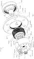
FIG. 1 is an exploded view of a gear box according to an embodiment; -
FIG. 2 is a side view of the gear box ofFIG. 1 ; -
FIG. 3 is a cross sectional view along section lines A-A of the gear box ofFIG. 2 ; -
FIG. 4 is a detail of section B of the gear box ofFIG. 3 and of section D of the gearbox ofFIG. 5 ; -
FIG. 5 is an exploded view of another gear box according to an embodiment; -
FIG. 6 is a side view of the gear box ofFIG. 5 ; -
FIG. 7 is a cross sectional view along section lines C-C of the gear box ofFIG. 6 ; and -
FIG. 8 is a flowchart of a method of operating the gearboxes ofFIGS. 1 and5 according to an embodiment. - A detailed description of one or more embodiments of the disclosed apparatus and method are presented herein by way of exemplification and not limitation with reference to the Figures.
- Compound harmonic gearboxes may enable achieving a relatively high power density. Known compound harmonic gears, however, have a limited range of rotational motion. In view of such limitations, the disclosed embodiments provide a compound harmonic gearbox configured for continuous output rotation. Benefits of the disclosed compound harmonic gearbox include broader and more efficient application with earth moving equipment, power tools, robot end effectors, power steering gearboxes, power lift gates, and the like.
- Turning to
FIGS. 1-4 , disclosed is a compound harmonic gearbox (gearbox) 100A according to an embodiment. Thegearbox 100A includes ground gears generally referred to as 110 including afirst ground gear 110A and asecond ground gear 110B. The ground gears 110 are interconnected about astationary shaft 120 to form a housing 130 (e.g.,FIG. 2 ). According to an embodiment only thefirst ground gear 110A includesgearbox mounting features 135. Thegearbox mounting features 135 may be threaded holes. - An
output flange 140 is partially encased within the housing 130. Aflex spline 150 is within the housing 130. Theflex spline 150 drives theoutput flange 140 from gear meshing, discussed in greater detail below. Awave generator 170 is within the housing 130. Thewave generator 170 drives theflex spline 150 from impulses generated from rotation of thewave generator 170. - An
input shaft 190 includes aninput gear 200 that drives thewave generator 170. Theinput shaft 190 extends along an axial direction A (axially) through an input-shaft channel 205 in thefirst ground gear 110A. The input-shaft channel 205 extends axially through a firstaxial end wall 210A of thefirst ground gear 110A. With the disclosed configuration theoutput flange 140 may rotate completely, (e.g., more than 360 degrees clockwise or counterclockwise) around thestationary shaft 120 with rotation of theinput shaft 190 in the same direction (or in an opposing direction, depending on theharmonic gears configuration 100A). - The
input gear 200 forms a first spur gear. Anaxial end 220 of thewave generator 170 forms asecond spur gear 230A. Theinput gear 200 andsecond spur gear 230A mesh to enable theinput gear 200 to drive thewave generator 170. - One or more input-
shaft bearings 240 are disposed in the input-shaft channel 205 for rotational positioning theinput shaft 190. Theinput shaft 190 is offset along a radial direction R (radially) from an axial center A of thestationary shaft 120. - A stationary-shaft bearing 250 is provided between the
stationary shaft 120 and thewave generator 170. Aportion 260 of thestationary shaft 120 forms a stationary-shaft inner race. A stationary-shaft bearingouter race 270 is disposed against thewave generator 170. A stationary-shaftbearing rolling element 280 is disposed between thestationary shaft 120 and the stationary-shaft bearingouter race 270. - A drive bearing 300 (e.g.,
FIG. 4 ) is disposed between thewave generator 170 and theflex spline 150. Thedrive bearing 300 includes a drive bearinginner race 310 disposed against thewave generator 170. A drive bearingouter race 320 is disposed against theflex spline 150. A drive bearing rollingelement 330 is between the drive bearinginner race 310 and the drive bearingouter race 320. Thedrive bearing 300 has a same axial span as theflex spline 150. Thedrive bearing 300 is axially aligned with theflex spline 150. - A first radial
outer shell 340 of thefirst ground gear 110A is disposed against a firstaxial side 350 of theoutput flange 140. A second radialouter shell 360 of thesecond ground gear 110B is disposed at a secondaxial side 370 of theoutput flange 140. From this configuration theoutput flange 140 is partially encased in the housing 130. There would be anaxial clearance 375 between both axial sides of theoutput flange 140 and theouter shells clearance 375 would allow for motion between theoutput flange 140 and the outer ground shells of the ground gear 110. - The
stationary shaft 120 extends axially from a secondaxial end wall 210B of thesecond ground gear 110B toward thefirst ground gear 110A. Thestationary shaft 120 is secured to the firstaxial end wall 210A of thefirst ground gear 110A, as discussed in further detail below. This configuration forms the housing 130. - The first
axial end wall 210A includes anopening 400. The opening 400 forms a keyway. Anaxial end 410 of thestationary shaft 120 forms a key 415. This configuration prevents relative rotational motion between the ground gears 110 when connected. Theaxial end 410 of thestationary shaft 120 is includes threadedtip 416 configured to receive anut 417. Thenut 417 secures the ground gears 110 to one another. This configuration secures the housing 130 at theoutput flange 140, leaving theclearance 375 between theoutput flange 140 and theouter shells - The
gearbox 100A further includes a plurality of support bearings 412 (e.g.,FIG. 3 ). The plurality of support bearings 412 include a first support bearing 412A and a second support bearing 412B. The plurality of support bearings 412 are positioned at axially opposing ends of theflex spline 150 and drive bearing 300. According to a disclosed embodiment, the plurality of support bearings 412 are ball bearings. - The
flex spline 150 includes a plurality of splines 420 (e.g.,FIG. 4 ) to thereby form a compound spline. For example, theflex spline 150 includes afirst ground spline 420A, asecond ground spline 420B and anoutput spline 420C. Thesecond ground spline 420B is axially offset from thefirst ground spline 420A. Theoutput spline 420C is axially intermediate thefirst ground spline 420A and thesecond ground spline 420B. Each of thefirst ground spline 420A, thesecond ground spline 420B and theoutput spline 420C are outer facing splines. - The
first ground gear 110A includes first ground gear teeth 430A. The first ground gear teeth 430A mesh with thefirst ground spline 420A. Thesecond ground gear 110B includes secondground gear teeth 430B. The secondground gear teeth 430B mesh with thesecond ground spline 420B. Theoutput flange 140 includesoutput gear teeth 430C. Theoutput gear teeth 430C mesh with theoutput spline 420C. Each of the first ground gear teeth 430A, the secondground gear teeth 430B and theoutput gear teeth 430C are inner facing teeth. - The plurality of splines 420 are configured to mesh with the ground gears 110 and the
output flange 140 according to different gear ratios. Thefirst ground spline 420A and the first ground gear teeth 430A have a first gear ratio (Ratio 1, below). Thesecond ground spline 420B and the secondground gear teeth 430B also have the first gear ratio. Theoutput spline 420C and theoutput gear teeth 430C have a second gear ratio (Ratio 2, below) that differs from the first gear ratio. The splines 420 are integral to same structure, that is, theflex spline 150. Thus the different gear ratios together form a compound gear ratio (Compound Ratio, below). The compound gear ratio provides a differential motion between the ground gears 110 and theoutput flange 140. - The compound gear ratio is represented as the difference of the individual gear ratios:


- The
second spur gear 230A and the first ground gear teeth 430A are axially positioned at axially opposing ends of the stationary-shaft bearing 250 (e.g.,FIG. 3 ). The first support bearing 412A is positioned axially intermediate thesecond spur gear 230A and the first ground gear teeth 430A. - Turning to
FIGS. 5-7 , disclosed is a second compound harmonic gearbox (the second gearbox) 100A according to an embodiment. Aspects of thesecond gearbox 100B shall be identified as by same reference numbers as aspects of thegearbox 100A ofFIGS. 1-4 . Differences, if any, are those expressly identified below. - The
second gearbox 100B includes ground gears generally referred to as 110 including afirst ground gear 110A and asecond ground gear 110B. The ground gears 110 are interconnected about astationary shaft 120 to form a housing 130 (e.g.,FIG. 6 ). According to an embodiment only thefirst ground gear 110A includes gearbox mounting features 135. The gearbox mounting features 135 may be threaded holes. - An
output flange 140 is partially encased within the housing 130. Aflex spline 150 is within the housing 130. Theflex spline 150 drives theoutput flange 140 from gear meshing, discussed in greater detail below. Awave generator 170 is within the housing 130. Thewave generator 170 drives theflex spline 150 from impulses generated from rotation of thewave generator 170. - An
input shaft 190 includes aninput gear 200 that drives thewave generator 170. Theinput shaft 190 extends radially through an input-shaft channel 205 in thefirst ground gear 110A. The input-shaft channel 205 extends radially through a first radialouter shell 340 of thefirst ground gear 110A. With the disclosed configuration theoutput flange 140 may rotate completely, more than 360 degrees clockwise or counterclockwise, around thestationary shaft 120 with rotation of theinput shaft 190 in one direction or another direction. As illustrated, theinput shaft 190 andoutput flange 140 rotate perpendicularly to one another. - The
input gear 200 forms a first bevel gear. Anaxial end 220 of thewave generator 170 forms asecond bevel gear 230B. Theinput gear 200 andsecond bevel gear 230B mesh to enable theinput gear 200 to drive thewave generator 170. - One or more input-
shaft bearings 240 are disposed in the input-shaft channel 205 for rotational positioning theinput shaft 190. - A stationary-
shaft bearing 250 is provided between thestationary shaft 120 and thewave generator 170. Aportion 260 of thestationary shaft 120 forms a stationary-shaft bearing inner race. A stationary-shaft bearingouter race 270 is disposed against thewave generator 170. A stationary-shaftbearing rolling element 280 is disposed between thestationary shaft 120 and the stationary-shaft bearingouter race 270. - A drive bearing 300 (e.g.,
FIG. 4 , which is equally applicable in this embodiment) is disposed between thewave generator 170 and theflex spline 150. Thedrive bearing 300 includes a drive bearinginner race 310 disposed against thewave generator 170. A drive bearingouter race 320 is disposed against theflex spline 150. Drive bearingrolling elements 330 are between the drive bearinginner race 310 and the drive bearingouter race 320. Thedrive bearing 300 has a same axial span as theflex spline 150. Thedrive bearing 300 is axially aligned with theflex spline 150. - The first radial
outer shell 340 of thefirst ground gear 110A is disposed against a firstaxial side 350 of theoutput flange 140. A second radialouter shell 360 of thesecond ground gear 110B is disposed against a secondaxial side 370 of theoutput flange 140. From this configuration theoutput flange 140 is partially encased in the housing 130. - The
stationary shaft 120 extends axially from a secondaxial end wall 210B of thesecond ground gear 110B toward thefirst ground gear 110A. Thestationary shaft 120 is secured to a firstaxial end wall 210A of thefirst ground gear 110A, as discussed in further detail below. This configuration forms the housing 130. - The first
axial end wall 210A includes anopening 400. The opening 400 forms a keyway. Anaxial end 410 of thestationary shaft 120 is formed to include a key 415. This configuration prevents relative rotational motion between the ground gears 110 when connected. Theaxial end 410 of thestationary shaft 120 is includes threadedtip 416 configured to receive anut 417. Thenut 417 secures the ground gears 110 to one another. This configuration secures the housing 130 at theoutput flange 140, leaving theclearance 375 between theoutput flange 140 and theouter shells - The
gearbox 100A further includes a plurality of support bearings 412 (e.g.,FIG. 7 ). The plurality of support bearings 412 include a first support bearing 412A and a second support bearing 412B. The plurality of support bearings 412 are positioned at axially opposing ends of theflex spline 150 and drive bearing 300. According to a disclosed embodiment, the plurality of support bearings 412 are ball bearings. - The
flex spline 150 includes a plurality of splines 420 (e.g.,FIG. 4 ) to thereby form a compound spline. For example, theflex spline 150 includes afirst ground spline 420A, asecond ground spline 420B and anoutput spline 420C. Thesecond ground spline 420B is axially offset from thefirst ground spline 420A. Theoutput spline 420C is axially intermediate thefirst ground spline 420A and thesecond ground spline 420B. Each of thefirst ground spline 420A, thesecond ground spline 420B and theoutput spline 420C are outer facing splines. - The
first ground gear 110A includes first ground gear teeth 430A. The first ground gear teeth 430A mesh with thefirst ground spline 420A. Thesecond ground gear 110B includes secondground gear teeth 430B. The secondground gear teeth 430B mesh with thesecond ground spline 420B. Theoutput flange 140 includesoutput gear teeth 430C. Theoutput gear teeth 430C mesh with theoutput spline 420C. Each of the first ground gear teeth 430A, the secondground gear teeth 430B and theoutput gear teeth 430C are inner facing teeth. - The plurality of splines 420 are configured to mesh with the ground gears 110 and the
output flange 140 according to different gear ratios. Thefirst ground spline 420A and the first ground gear teeth 430A have a first gear ratio (Ratio 1, below). Thesecond ground spline 420B and the secondground gear teeth 430B also have the first gear ratio. Theoutput spline 420C and theoutput gear teeth 430C have a second gear ratio (Ratio 2, below) that differs from the first gear ratio. The splines 420 are integral to same structure, that is, theflex spline 150. Thus the different gear ratios together form a compound gear ratio (Compound Ratio, below). The compound gear ratio provides a differential motion between the ground gears 110 and theoutput flange 140. - The compound gear ratio is represented as the difference of the individual gear ratios:


- The
second bevel gear 230B and the first ground gear teeth 430A are at axially positioned at axially opposing ends of the stationary-shaft bearing 250 (e.g.,FIG. 7 ). The first support bearing 412A is positioned axially intermediate thesecond bevel gear 230B and the first ground gear teeth 430A. - The above configurations are balanced to react all generated loads through the gearbox mounting features 135 on the
first ground gear 110A. From the above configuration an external movable structure connected to theoutput flange 140 may rotate relative to an external stationary structure connected to thefirst ground gear 110A and theinput shaft 190. Such external stationary structure and external movable structure may be components of, for example, earth moving equipment, power tools, robot end effectors, power steering gearboxes, power lift gates, and the like. - Turning to
FIG. 8 , a flowchart shows a method of operating thegearbox 100A (or 100B). As shown inblock 510, the method includes rotating aninput shaft 190 that extends through one of a firstaxial end wall 210A of afirst ground gear 110A or a first radialouter shell 340 of thefirst ground gear 110A. As indicated thefirst ground gear 110A is interconnected with asecond ground gear 110B about thestationary shaft 120 to form the housing 130. Additionally, only thefirst ground gear 110A includes gearbox mounting features 135. As shown inblock 520 the method includes rotating aninput gear 200 by rotating theinput shaft 190. As shown inblock 530 the method includes rotating awave generator 170 by rotating by rotation theinput gear 200. Thewave generator 170 is configured for rotating completely around astationary shaft 120 of thegearbox 100A (or 100B). As shown inblock 530 the method includes rotating theflex spline 150 by rotating thewave generator 170. As shown inblock 540 the method includes rotating theoutput flange 140 by rotating theflex spline 150. From this action, theoutput flange 140 rotates completely around thestationary shaft 120. - The terminology used herein is for the purpose of describing particular embodiments only and is not intended to be limiting of the present disclosure. As used herein, the singular forms "a", "an" and "the" are intended to include the plural forms as well, unless the context clearly indicates otherwise. It will be further understood that the terms "comprises" and/or "comprising," when used in this specification, specify the presence of stated features, integers, steps, operations, elements, and/or components, but do not preclude the presence or addition of one or more other features, integers, steps, operations, element components, and/or groups thereof.
- While the present disclosure has been described with reference to an exemplary embodiment or embodiments, it will be understood by those skilled in the art that various changes may be made and equivalents may be substituted for elements thereof without departing from the scope of the present disclosure. In addition, many modifications may be made to adapt a particular situation or material to the teachings of the present disclosure without departing from the essential scope thereof. Therefore, it is intended that the present disclosure not be limited to the particular embodiment disclosed as the best mode contemplated for carrying out this present disclosure, but that the present disclosure will include all embodiments falling within the scope of the claims.
Claims (15)
- A compound harmonic gearbox (100A) comprising:a first ground gear (110A) and a second ground gear (110B) being interconnected about a stationary shaft to form a housing, wherein only the first ground gear includes gearbox mounting features;an output flange (140) partially encased within the housing;a flex spline (150) within the housing that drives the output flange;a wave generator (170) within the housing that drives the flex spline;an input shaft (190) with an input gear that drives the wave generator, the input shaft extending through the first ground gear, wherein the output flange is configured to rotate completely around the stationary shaft by rotating the input shaft.
- The gearbox of claim 1, wherein the input shaft extends through an input-shaft channel in one of a first axial end wall of the first ground gear and a first radial outer shell of the first ground gear.
- The gearbox of claim 2, wherein one or more input-shaft bearings are disposed in the input-shaft channel for rotational positioning of the input shaft.
- The gearbox of claim 3, wherein:the input shaft extends axially through the first axial end wall and is radially offset from an axial center of the stationary shaft; andthe input gear defines a first spur gear, and an axial end of the wave generator defines a second spur gear that meshes with the first spur gear.
- The gearbox of claim 3, wherein:the input shaft extends radially through the first radial outer shell of the first ground gear; andthe input gear defines a first bevel gear and an axial end of the wave generator defines a second bevel gear that meshes with the input gear.
- The gearbox of any preceding claim, further comprising a stationary-shaft bearing, wherein:a portion of the stationary shaft defines a stationary-shaft bearing inner race;a stationary-shaft bearing outer race is connected to the wave generator; anda stationary-shaft bearing rolling element is disposed therebetween.
- The gearbox of any preceding claim, further comprising a drive bearing including a drive bearing inner race connected to the wave generator, a drive bearing outer race connected to the flex spline, and a drive bearing rolling element therebetween, and
optionally wherein the drive bearing and the flex spline have a same axial span and are axially aligned with one another. - The gearbox of claim 7, wherein the first radial outer shell of the first ground gear is disposed against a first axial side of the output flange and a second radial outer shell of the second ground gear is disposed against a second axial side of the output flange, whereby the output flange is partially encased in the housing.
- The gearbox of claim 8, wherein the stationary shaft extends axially from a second axial end wall of the second ground gear and is secured to the first axial end wall of the first ground gear to thereby form the housing.
- The gearbox of claim 9, wherein the first axial end wall includes an opening that forms a keyway and the stationary shaft includes a key.
- The gearbox of claim 10, wherein the axial end of the stationary shaft includes a threaded tip configured to receive a nut to secure the first ground gear and the second ground gear to one another, thereby securing the housing at the output flange, and optionally further comprising a plurality of support bearings respectively disposed on axially opposing ends of the flex spline.
- The gearbox of any preceding claim, wherein the flex spline includes a plurality of splines that are outer facing, including an output spline, a first ground spline on one side of the output spline and a second ground spline on another side of the output spline, so that the second ground spline is axially offset from the first ground spline, and the output spline is axially between the first ground spline and the second ground spline, whereby the flex spline is configured as a compound spline, and optionally
wherein the output flange includes output gear teeth that mesh with the output spline, the first ground gear includes first ground gear teeth that mesh with the first ground spline, and the second ground gear includes second ground gear teeth that mesh with the second ground spline. - The gearbox of claim 12, wherein the first ground spline and the first ground gear teeth are configured to mesh to thereby form a first gear ratio, and the output spline and the output gear teeth are configured to mesh to thereby form a second gear ratio that differs from the first gear ratio to form a compound gear ratio, and optionally wherein the second ground spline and the second ground gear teeth are configured to mesh and form the first gear ratio.
- The gearbox of claim 12, wherein:the second spur gear and the first ground gear teeth are axially positioned at axially opposing ends of the stationary-shaft bearing; anda first support bearing of the plurality of support bearings is positioned axially intermediate the second spur gear and the first ground gear teeth, and optionally wherein the gearbox mounting features are threaded-holes.
- A method of operating a compound harmonic gearbox, comprising:rotating an input shaft (190) that extends through one of a first axial end wall of a first ground gear or a first radial outer shell of the first ground gear, wherein the first ground gear is interconnected with a second ground gear about a stationary shaft to form a housing, and only the first ground gear includes gearbox mounting features;rotating an input gear by rotating the input shaft;rotating a wave generator by rotating the input gear, the wave generator rotating completely around the stationary shaft of the gearbox;rotating a flex spline (150) by rotating the wave generator; androtating an output flange (140) by rotating the flex spline, whereby the output flange rotates completely around the stationary shaft.
Applications Claiming Priority (1)
| Application Number | Priority Date | Filing Date | Title |
|---|---|---|---|
| US16/566,174 US11371596B2 (en) | 2019-09-10 | 2019-09-10 | Compound harmonic gearbox configured for continuous output rotation |
Publications (2)
| Publication Number | Publication Date |
|---|---|
| EP3792524A1 true EP3792524A1 (en) | 2021-03-17 |
| EP3792524B1 EP3792524B1 (en) | 2025-06-18 |
Family
ID=68762636
Family Applications (1)
| Application Number | Title | Priority Date | Filing Date |
|---|---|---|---|
| EP19212912.0A Active EP3792524B1 (en) | 2019-09-10 | 2019-12-02 | Compound harmonic gearbox configured for continuous output rotation |
Country Status (3)
| Country | Link |
|---|---|
| US (1) | US11371596B2 (en) |
| EP (1) | EP3792524B1 (en) |
| CA (1) | CA3064543A1 (en) |
Cited By (1)
| Publication number | Priority date | Publication date | Assignee | Title |
|---|---|---|---|---|
| EP4414587A1 (en) * | 2023-02-13 | 2024-08-14 | Hamilton Sundstrand Corporation | Harmonic drive with flex spline end clamps |
Families Citing this family (2)
| Publication number | Priority date | Publication date | Assignee | Title |
|---|---|---|---|---|
| US12072009B2 (en) * | 2022-05-27 | 2024-08-27 | Hamilton Sundstrand Corporation | Harmonic gearset with split flexspline |
| EP4421352A1 (en) * | 2023-02-23 | 2024-08-28 | Hamilton Sundstrand Corporation | Flex spline for strain wave drive |
Citations (6)
| Publication number | Priority date | Publication date | Assignee | Title |
|---|---|---|---|---|
| DE1905192A1 (en) * | 1969-02-03 | 1970-08-06 | Usm Corp | Rotary drive device |
| DE2505155A1 (en) * | 1975-02-07 | 1976-08-19 | Inschenerno Str I Im W W Kuiby | Reduction gear drive utilising flexible toothed wheel - provides large reduction ratio with compactness and low weight and positive drive |
| EP3165795A1 (en) * | 2015-10-16 | 2017-05-10 | Hamilton Sundstrand Corporation | Flex spine for use with a compound harmonic generator |
| EP3276209A1 (en) * | 2016-07-30 | 2018-01-31 | UBTech Robotics Corp. | Servomotor and control method thereof |
| EP3312475A2 (en) * | 2016-10-20 | 2018-04-25 | Hamilton Sundstrand Corporation | Compound harmonic drive assembly |
| CN110145586A (en) * | 2019-06-19 | 2019-08-20 | 廊坊市钦纵传动科技有限公司 | Orthogonal shaft harmonic reducer |
Family Cites Families (7)
| Publication number | Priority date | Publication date | Assignee | Title |
|---|---|---|---|---|
| US4003272A (en) * | 1975-01-31 | 1977-01-18 | Dmitry Pavlovich Volkov | Harmonic gear reduction unit |
| US5061227A (en) * | 1989-11-13 | 1991-10-29 | Renk Aktiengesellschaft | Bearing system for wave generator drive |
| US9157517B2 (en) | 2013-09-16 | 2015-10-13 | Hamilton Sundstrand Corporation | Compound harmonic drive |
| US9371899B2 (en) * | 2014-05-27 | 2016-06-21 | Hamilton Sundstrand Corporation | Harmonic drive assembly with selective disconnect and reconnect |
| US10823268B2 (en) | 2016-08-05 | 2020-11-03 | Hamilton Sunstrand Corporation | Inverted compound harmonic drive |
| US11092224B2 (en) | 2017-10-10 | 2021-08-17 | Hamilton Sundstrand Corporation | Method of developing spline profile |
| KR20220044483A (en) * | 2019-06-13 | 2022-04-08 | 서큘러 웨이브 드라이브 파트너스 인크. | circular wave drive |
-
2019
- 2019-09-10 US US16/566,174 patent/US11371596B2/en active Active
- 2019-12-02 EP EP19212912.0A patent/EP3792524B1/en active Active
- 2019-12-10 CA CA3064543A patent/CA3064543A1/en active Pending
Patent Citations (6)
| Publication number | Priority date | Publication date | Assignee | Title |
|---|---|---|---|---|
| DE1905192A1 (en) * | 1969-02-03 | 1970-08-06 | Usm Corp | Rotary drive device |
| DE2505155A1 (en) * | 1975-02-07 | 1976-08-19 | Inschenerno Str I Im W W Kuiby | Reduction gear drive utilising flexible toothed wheel - provides large reduction ratio with compactness and low weight and positive drive |
| EP3165795A1 (en) * | 2015-10-16 | 2017-05-10 | Hamilton Sundstrand Corporation | Flex spine for use with a compound harmonic generator |
| EP3276209A1 (en) * | 2016-07-30 | 2018-01-31 | UBTech Robotics Corp. | Servomotor and control method thereof |
| EP3312475A2 (en) * | 2016-10-20 | 2018-04-25 | Hamilton Sundstrand Corporation | Compound harmonic drive assembly |
| CN110145586A (en) * | 2019-06-19 | 2019-08-20 | 廊坊市钦纵传动科技有限公司 | Orthogonal shaft harmonic reducer |
Cited By (2)
| Publication number | Priority date | Publication date | Assignee | Title |
|---|---|---|---|---|
| EP4414587A1 (en) * | 2023-02-13 | 2024-08-14 | Hamilton Sundstrand Corporation | Harmonic drive with flex spline end clamps |
| US12215769B2 (en) | 2023-02-13 | 2025-02-04 | Hamilton Sundstrand Corporation | Harmonic drive with flex spline end clamps |
Also Published As
| Publication number | Publication date |
|---|---|
| US11371596B2 (en) | 2022-06-28 |
| US20210071744A1 (en) | 2021-03-11 |
| CA3064543A1 (en) | 2021-03-10 |
| BR102019026299A2 (en) | 2021-03-16 |
| EP3792524B1 (en) | 2025-06-18 |
Similar Documents
| Publication | Publication Date | Title |
|---|---|---|
| EP1279867B1 (en) | Power-split-transmission | |
| EP3792524B1 (en) | Compound harmonic gearbox configured for continuous output rotation | |
| DE102004014707B4 (en) | Planetary gear system with oscillating inner gear body | |
| DE69113561T2 (en) | BALANCING DEVICE FOR MOTORS. | |
| JP4947884B2 (en) | Method for manufacturing pin of planetary rotating member of planetary reduction mechanism | |
| JP5156961B2 (en) | Reduction gear | |
| JP6137875B2 (en) | Planetary gear reducer | |
| DE102014103363A1 (en) | DRIVE MODULE WITH SPRAY COOLING OF AN ELECTRIC MOTOR | |
| US11519487B2 (en) | Compound harmonic gear motor configured for continuous output rotation | |
| DE102013002310A1 (en) | Power transmission device for use in precision industrial robots, has inner bearing arranged on reduction gear side in axial direction, and support element integrated with primary element, in which inner periphery of inner bearing is fitted | |
| EP3692276A1 (en) | Integrated slew drive | |
| DE102007011895A1 (en) | Spurraddzialzial and overlay differential with the spur gear differential | |
| WO2019242979A1 (en) | Wheel drive module with supporting device | |
| US20160169360A1 (en) | Differential device | |
| EP3464894B1 (en) | Wind turbine transmission | |
| EP3152461B1 (en) | Planetary gearbox with two sun wheels | |
| DE102016211559A1 (en) | A drive system for driving a component having an electric motor unit and a gear unit | |
| EP2210714A1 (en) | Manipulator with an external rotor motor | |
| EP1398526B1 (en) | Compound differential planetary gear assembly | |
| EP0622544B1 (en) | Adjusting mechanism for axial-flow pump blades | |
| WO2025031820A1 (en) | Planetary carrier assembly for a planetary transmission, and drive means with a planetary transmission of this type | |
| DE202022100670U1 (en) | propulsion device and electric vehicle | |
| EP3482074B1 (en) | Bell housing for a wind turbine gear mechanism | |
| DE202018103547U1 (en) | Wheel drive module with support device | |
| DE102020125690A1 (en) | drive system |
Legal Events
| Date | Code | Title | Description |
|---|---|---|---|
| PUAI | Public reference made under article 153(3) epc to a published international application that has entered the european phase |
Free format text: ORIGINAL CODE: 0009012 |
|
| STAA | Information on the status of an ep patent application or granted ep patent |
Free format text: STATUS: THE APPLICATION HAS BEEN PUBLISHED |
|
| AK | Designated contracting states |
Kind code of ref document: A1 Designated state(s): AL AT BE BG CH CY CZ DE DK EE ES FI FR GB GR HR HU IE IS IT LI LT LU LV MC MK MT NL NO PL PT RO RS SE SI SK SM TR |
|
| AX | Request for extension of the european patent |
Extension state: BA ME |
|
| STAA | Information on the status of an ep patent application or granted ep patent |
Free format text: STATUS: REQUEST FOR EXAMINATION WAS MADE |
|
| 17P | Request for examination filed |
Effective date: 20210917 |
|
| RBV | Designated contracting states (corrected) |
Designated state(s): AL AT BE BG CH CY CZ DE DK EE ES FI FR GB GR HR HU IE IS IT LI LT LU LV MC MK MT NL NO PL PT RO RS SE SI SK SM TR |
|
| STAA | Information on the status of an ep patent application or granted ep patent |
Free format text: STATUS: EXAMINATION IS IN PROGRESS |
|
| 17Q | First examination report despatched |
Effective date: 20220125 |
|
| GRAP | Despatch of communication of intention to grant a patent |
Free format text: ORIGINAL CODE: EPIDOSNIGR1 |
|
| STAA | Information on the status of an ep patent application or granted ep patent |
Free format text: STATUS: GRANT OF PATENT IS INTENDED |
|
| INTG | Intention to grant announced |
Effective date: 20250116 |
|
| GRAS | Grant fee paid |
Free format text: ORIGINAL CODE: EPIDOSNIGR3 |
|
| GRAA | (expected) grant |
Free format text: ORIGINAL CODE: 0009210 |
|
| STAA | Information on the status of an ep patent application or granted ep patent |
Free format text: STATUS: THE PATENT HAS BEEN GRANTED |
|
| AK | Designated contracting states |
Kind code of ref document: B1 Designated state(s): AL AT BE BG CH CY CZ DE DK EE ES FI FR GB GR HR HU IE IS IT LI LT LU LV MC MK MT NL NO PL PT RO RS SE SI SK SM TR |
|
| REG | Reference to a national code |
Ref country code: GB Ref legal event code: FG4D |
|
| REG | Reference to a national code |
Ref country code: CH Ref legal event code: EP |
|
| REG | Reference to a national code |
Ref country code: DE Ref legal event code: R096 Ref document number: 602019071194 Country of ref document: DE |
|
| REG | Reference to a national code |
Ref country code: CH Ref legal event code: EP |
|
| REG | Reference to a national code |
Ref country code: IE Ref legal event code: FG4D |
|
| PG25 | Lapsed in a contracting state [announced via postgrant information from national office to epo] |
Ref country code: FI Free format text: LAPSE BECAUSE OF FAILURE TO SUBMIT A TRANSLATION OF THE DESCRIPTION OR TO PAY THE FEE WITHIN THE PRESCRIBED TIME-LIMIT Effective date: 20250618 |
|
| REG | Reference to a national code |
Ref country code: LT Ref legal event code: MG9D |
|
| PG25 | Lapsed in a contracting state [announced via postgrant information from national office to epo] |
Ref country code: GR Free format text: LAPSE BECAUSE OF FAILURE TO SUBMIT A TRANSLATION OF THE DESCRIPTION OR TO PAY THE FEE WITHIN THE PRESCRIBED TIME-LIMIT Effective date: 20250919 Ref country code: NO Free format text: LAPSE BECAUSE OF FAILURE TO SUBMIT A TRANSLATION OF THE DESCRIPTION OR TO PAY THE FEE WITHIN THE PRESCRIBED TIME-LIMIT Effective date: 20250918 |
|
| PG25 | Lapsed in a contracting state [announced via postgrant information from national office to epo] |
Ref country code: BG Free format text: LAPSE BECAUSE OF FAILURE TO SUBMIT A TRANSLATION OF THE DESCRIPTION OR TO PAY THE FEE WITHIN THE PRESCRIBED TIME-LIMIT Effective date: 20250618 |
|
| PG25 | Lapsed in a contracting state [announced via postgrant information from national office to epo] |
Ref country code: HR Free format text: LAPSE BECAUSE OF FAILURE TO SUBMIT A TRANSLATION OF THE DESCRIPTION OR TO PAY THE FEE WITHIN THE PRESCRIBED TIME-LIMIT Effective date: 20250618 |
|
| PG25 | Lapsed in a contracting state [announced via postgrant information from national office to epo] |
Ref country code: RS Free format text: LAPSE BECAUSE OF FAILURE TO SUBMIT A TRANSLATION OF THE DESCRIPTION OR TO PAY THE FEE WITHIN THE PRESCRIBED TIME-LIMIT Effective date: 20250918 |
|
| REG | Reference to a national code |
Ref country code: NL Ref legal event code: MP Effective date: 20250618 |
|
| PG25 | Lapsed in a contracting state [announced via postgrant information from national office to epo] |
Ref country code: LV Free format text: LAPSE BECAUSE OF FAILURE TO SUBMIT A TRANSLATION OF THE DESCRIPTION OR TO PAY THE FEE WITHIN THE PRESCRIBED TIME-LIMIT Effective date: 20250618 |
|
| PG25 | Lapsed in a contracting state [announced via postgrant information from national office to epo] |
Ref country code: NL Free format text: LAPSE BECAUSE OF FAILURE TO SUBMIT A TRANSLATION OF THE DESCRIPTION OR TO PAY THE FEE WITHIN THE PRESCRIBED TIME-LIMIT Effective date: 20250618 |
|
| PG25 | Lapsed in a contracting state [announced via postgrant information from national office to epo] |
Ref country code: PT Free format text: LAPSE BECAUSE OF FAILURE TO SUBMIT A TRANSLATION OF THE DESCRIPTION OR TO PAY THE FEE WITHIN THE PRESCRIBED TIME-LIMIT Effective date: 20251020 |
|
| REG | Reference to a national code |
Ref country code: AT Ref legal event code: MK05 Ref document number: 1804429 Country of ref document: AT Kind code of ref document: T Effective date: 20250618 |
|
| PG25 | Lapsed in a contracting state [announced via postgrant information from national office to epo] |
Ref country code: IS Free format text: LAPSE BECAUSE OF FAILURE TO SUBMIT A TRANSLATION OF THE DESCRIPTION OR TO PAY THE FEE WITHIN THE PRESCRIBED TIME-LIMIT Effective date: 20251018 |
|
| PGFP | Annual fee paid to national office [announced via postgrant information from national office to epo] |
Ref country code: GB Payment date: 20251229 Year of fee payment: 7 |
|
| PG25 | Lapsed in a contracting state [announced via postgrant information from national office to epo] |
Ref country code: SM Free format text: LAPSE BECAUSE OF FAILURE TO SUBMIT A TRANSLATION OF THE DESCRIPTION OR TO PAY THE FEE WITHIN THE PRESCRIBED TIME-LIMIT Effective date: 20250618 Ref country code: AT Free format text: LAPSE BECAUSE OF FAILURE TO SUBMIT A TRANSLATION OF THE DESCRIPTION OR TO PAY THE FEE WITHIN THE PRESCRIBED TIME-LIMIT Effective date: 20250618 |
|
| PGFP | Annual fee paid to national office [announced via postgrant information from national office to epo] |
Ref country code: IT Payment date: 20251210 Year of fee payment: 7 |
|
| PGFP | Annual fee paid to national office [announced via postgrant information from national office to epo] |
Ref country code: FR Payment date: 20251230 Year of fee payment: 7 |
|
| PG25 | Lapsed in a contracting state [announced via postgrant information from national office to epo] |
Ref country code: CZ Free format text: LAPSE BECAUSE OF FAILURE TO SUBMIT A TRANSLATION OF THE DESCRIPTION OR TO PAY THE FEE WITHIN THE PRESCRIBED TIME-LIMIT Effective date: 20250618 |
|
| PG25 | Lapsed in a contracting state [announced via postgrant information from national office to epo] |
Ref country code: PL Free format text: LAPSE BECAUSE OF FAILURE TO SUBMIT A TRANSLATION OF THE DESCRIPTION OR TO PAY THE FEE WITHIN THE PRESCRIBED TIME-LIMIT Effective date: 20250618 |
|
| PG25 | Lapsed in a contracting state [announced via postgrant information from national office to epo] |
Ref country code: EE Free format text: LAPSE BECAUSE OF FAILURE TO SUBMIT A TRANSLATION OF THE DESCRIPTION OR TO PAY THE FEE WITHIN THE PRESCRIBED TIME-LIMIT Effective date: 20250618 |
|
| PG25 | Lapsed in a contracting state [announced via postgrant information from national office to epo] |
Ref country code: SK Free format text: LAPSE BECAUSE OF FAILURE TO SUBMIT A TRANSLATION OF THE DESCRIPTION OR TO PAY THE FEE WITHIN THE PRESCRIBED TIME-LIMIT Effective date: 20250618 Ref country code: RO Free format text: LAPSE BECAUSE OF FAILURE TO SUBMIT A TRANSLATION OF THE DESCRIPTION OR TO PAY THE FEE WITHIN THE PRESCRIBED TIME-LIMIT Effective date: 20250618 |
|
| PG25 | Lapsed in a contracting state [announced via postgrant information from national office to epo] |
Ref country code: ES Free format text: LAPSE BECAUSE OF FAILURE TO SUBMIT A TRANSLATION OF THE DESCRIPTION OR TO PAY THE FEE WITHIN THE PRESCRIBED TIME-LIMIT Effective date: 20250618 |
|
| REG | Reference to a national code |
Ref country code: DE Ref legal event code: R097 Ref document number: 602019071194 Country of ref document: DE |
|
| PG25 | Lapsed in a contracting state [announced via postgrant information from national office to epo] |
Ref country code: DK Free format text: LAPSE BECAUSE OF FAILURE TO SUBMIT A TRANSLATION OF THE DESCRIPTION OR TO PAY THE FEE WITHIN THE PRESCRIBED TIME-LIMIT Effective date: 20250618 |
|
| PGFP | Annual fee paid to national office [announced via postgrant information from national office to epo] |
Ref country code: DE Payment date: 20251231 Year of fee payment: 7 |
|
| PLBE | No opposition filed within time limit |
Free format text: ORIGINAL CODE: 0009261 |
|
| STAA | Information on the status of an ep patent application or granted ep patent |
Free format text: STATUS: NO OPPOSITION FILED WITHIN TIME LIMIT |
|
| REG | Reference to a national code |
Ref country code: CH Ref legal event code: L10 Free format text: ST27 STATUS EVENT CODE: U-0-0-L10-L00 (AS PROVIDED BY THE NATIONAL OFFICE) Effective date: 20260430 |