EP3792515A1 - Clutch assembly - Google Patents
Clutch assembly Download PDFInfo
- Publication number
- EP3792515A1 EP3792515A1 EP20194682.9A EP20194682A EP3792515A1 EP 3792515 A1 EP3792515 A1 EP 3792515A1 EP 20194682 A EP20194682 A EP 20194682A EP 3792515 A1 EP3792515 A1 EP 3792515A1
- Authority
- EP
- European Patent Office
- Prior art keywords
- clutch
- output
- relative
- clutch drum
- pack
- Prior art date
- Legal status (The legal status is an assumption and is not a legal conclusion. Google has not performed a legal analysis and makes no representation as to the accuracy of the status listed.)
- Granted
Links
Images




Classifications
-
- F—MECHANICAL ENGINEERING; LIGHTING; HEATING; WEAPONS; BLASTING
- F16—ENGINEERING ELEMENTS AND UNITS; GENERAL MEASURES FOR PRODUCING AND MAINTAINING EFFECTIVE FUNCTIONING OF MACHINES OR INSTALLATIONS; THERMAL INSULATION IN GENERAL
- F16D—COUPLINGS FOR TRANSMITTING ROTATION; CLUTCHES; BRAKES
- F16D11/00—Clutches in which the members have interengaging parts
- F16D11/14—Clutches in which the members have interengaging parts with clutching members movable only axially
-
- F—MECHANICAL ENGINEERING; LIGHTING; HEATING; WEAPONS; BLASTING
- F16—ENGINEERING ELEMENTS AND UNITS; GENERAL MEASURES FOR PRODUCING AND MAINTAINING EFFECTIVE FUNCTIONING OF MACHINES OR INSTALLATIONS; THERMAL INSULATION IN GENERAL
- F16D—COUPLINGS FOR TRANSMITTING ROTATION; CLUTCHES; BRAKES
- F16D25/00—Fluid-actuated clutches
- F16D25/06—Fluid-actuated clutches in which the fluid actuates a piston incorporated in, i.e. rotating with the clutch
- F16D25/061—Fluid-actuated clutches in which the fluid actuates a piston incorporated in, i.e. rotating with the clutch the clutch having interengaging clutch members
-
- F—MECHANICAL ENGINEERING; LIGHTING; HEATING; WEAPONS; BLASTING
- F16—ENGINEERING ELEMENTS AND UNITS; GENERAL MEASURES FOR PRODUCING AND MAINTAINING EFFECTIVE FUNCTIONING OF MACHINES OR INSTALLATIONS; THERMAL INSULATION IN GENERAL
- F16D—COUPLINGS FOR TRANSMITTING ROTATION; CLUTCHES; BRAKES
- F16D13/00—Friction clutches
- F16D13/22—Friction clutches with axially-movable clutching members
- F16D13/38—Friction clutches with axially-movable clutching members with flat clutching surfaces, e.g. discs
- F16D13/52—Clutches with multiple lamellae ; Clutches in which three or more axially moveable members are fixed alternately to the shafts to be coupled and are pressed from one side towards an axially-located member
-
- F—MECHANICAL ENGINEERING; LIGHTING; HEATING; WEAPONS; BLASTING
- F16—ENGINEERING ELEMENTS AND UNITS; GENERAL MEASURES FOR PRODUCING AND MAINTAINING EFFECTIVE FUNCTIONING OF MACHINES OR INSTALLATIONS; THERMAL INSULATION IN GENERAL
- F16D—COUPLINGS FOR TRANSMITTING ROTATION; CLUTCHES; BRAKES
- F16D13/00—Friction clutches
- F16D13/58—Details
-
- F—MECHANICAL ENGINEERING; LIGHTING; HEATING; WEAPONS; BLASTING
- F16—ENGINEERING ELEMENTS AND UNITS; GENERAL MEASURES FOR PRODUCING AND MAINTAINING EFFECTIVE FUNCTIONING OF MACHINES OR INSTALLATIONS; THERMAL INSULATION IN GENERAL
- F16D—COUPLINGS FOR TRANSMITTING ROTATION; CLUTCHES; BRAKES
- F16D13/00—Friction clutches
- F16D13/58—Details
- F16D13/583—Diaphragm-springs, e.g. Belleville
- F16D13/585—Arrangements or details relating to the mounting or support of the diaphragm on the clutch on the clutch cover or the pressure plate
-
- F—MECHANICAL ENGINEERING; LIGHTING; HEATING; WEAPONS; BLASTING
- F16—ENGINEERING ELEMENTS AND UNITS; GENERAL MEASURES FOR PRODUCING AND MAINTAINING EFFECTIVE FUNCTIONING OF MACHINES OR INSTALLATIONS; THERMAL INSULATION IN GENERAL
- F16D—COUPLINGS FOR TRANSMITTING ROTATION; CLUTCHES; BRAKES
- F16D21/00—Systems comprising a plurality of actuated clutches
-
- F—MECHANICAL ENGINEERING; LIGHTING; HEATING; WEAPONS; BLASTING
- F16—ENGINEERING ELEMENTS AND UNITS; GENERAL MEASURES FOR PRODUCING AND MAINTAINING EFFECTIVE FUNCTIONING OF MACHINES OR INSTALLATIONS; THERMAL INSULATION IN GENERAL
- F16D—COUPLINGS FOR TRANSMITTING ROTATION; CLUTCHES; BRAKES
- F16D23/00—Details of mechanically-actuated clutches not specific for one distinct type
-
- F—MECHANICAL ENGINEERING; LIGHTING; HEATING; WEAPONS; BLASTING
- F16—ENGINEERING ELEMENTS AND UNITS; GENERAL MEASURES FOR PRODUCING AND MAINTAINING EFFECTIVE FUNCTIONING OF MACHINES OR INSTALLATIONS; THERMAL INSULATION IN GENERAL
- F16D—COUPLINGS FOR TRANSMITTING ROTATION; CLUTCHES; BRAKES
- F16D23/00—Details of mechanically-actuated clutches not specific for one distinct type
- F16D23/02—Arrangements for synchronisation, also for power-operated clutches
- F16D23/04—Arrangements for synchronisation, also for power-operated clutches with an additional friction clutch
-
- F—MECHANICAL ENGINEERING; LIGHTING; HEATING; WEAPONS; BLASTING
- F16—ENGINEERING ELEMENTS AND UNITS; GENERAL MEASURES FOR PRODUCING AND MAINTAINING EFFECTIVE FUNCTIONING OF MACHINES OR INSTALLATIONS; THERMAL INSULATION IN GENERAL
- F16D—COUPLINGS FOR TRANSMITTING ROTATION; CLUTCHES; BRAKES
- F16D25/00—Fluid-actuated clutches
- F16D25/06—Fluid-actuated clutches in which the fluid actuates a piston incorporated in, i.e. rotating with the clutch
- F16D25/062—Fluid-actuated clutches in which the fluid actuates a piston incorporated in, i.e. rotating with the clutch the clutch having friction surfaces
- F16D25/063—Fluid-actuated clutches in which the fluid actuates a piston incorporated in, i.e. rotating with the clutch the clutch having friction surfaces with clutch members exclusively moving axially
- F16D25/0635—Fluid-actuated clutches in which the fluid actuates a piston incorporated in, i.e. rotating with the clutch the clutch having friction surfaces with clutch members exclusively moving axially with flat friction surfaces, e.g. discs
- F16D25/0638—Fluid-actuated clutches in which the fluid actuates a piston incorporated in, i.e. rotating with the clutch the clutch having friction surfaces with clutch members exclusively moving axially with flat friction surfaces, e.g. discs with more than two discs, e.g. multiple lamellae
-
- F—MECHANICAL ENGINEERING; LIGHTING; HEATING; WEAPONS; BLASTING
- F16—ENGINEERING ELEMENTS AND UNITS; GENERAL MEASURES FOR PRODUCING AND MAINTAINING EFFECTIVE FUNCTIONING OF MACHINES OR INSTALLATIONS; THERMAL INSULATION IN GENERAL
- F16D—COUPLINGS FOR TRANSMITTING ROTATION; CLUTCHES; BRAKES
- F16D25/00—Fluid-actuated clutches
- F16D25/12—Details not specific to one of the before-mentioned types
-
- F—MECHANICAL ENGINEERING; LIGHTING; HEATING; WEAPONS; BLASTING
- F16—ENGINEERING ELEMENTS AND UNITS; GENERAL MEASURES FOR PRODUCING AND MAINTAINING EFFECTIVE FUNCTIONING OF MACHINES OR INSTALLATIONS; THERMAL INSULATION IN GENERAL
- F16D—COUPLINGS FOR TRANSMITTING ROTATION; CLUTCHES; BRAKES
- F16D28/00—Electrically-actuated clutches
-
- F—MECHANICAL ENGINEERING; LIGHTING; HEATING; WEAPONS; BLASTING
- F16—ENGINEERING ELEMENTS AND UNITS; GENERAL MEASURES FOR PRODUCING AND MAINTAINING EFFECTIVE FUNCTIONING OF MACHINES OR INSTALLATIONS; THERMAL INSULATION IN GENERAL
- F16D—COUPLINGS FOR TRANSMITTING ROTATION; CLUTCHES; BRAKES
- F16D13/00—Friction clutches
- F16D13/22—Friction clutches with axially-movable clutching members
- F16D13/38—Friction clutches with axially-movable clutching members with flat clutching surfaces, e.g. discs
- F16D13/52—Clutches with multiple lamellae ; Clutches in which three or more axially moveable members are fixed alternately to the shafts to be coupled and are pressed from one side towards an axially-located member
- F16D13/54—Clutches with multiple lamellae ; Clutches in which three or more axially moveable members are fixed alternately to the shafts to be coupled and are pressed from one side towards an axially-located member with means for increasing the effective force between the actuating sleeve or equivalent member and the pressure member
- F16D13/56—Clutches with multiple lamellae ; Clutches in which three or more axially moveable members are fixed alternately to the shafts to be coupled and are pressed from one side towards an axially-located member with means for increasing the effective force between the actuating sleeve or equivalent member and the pressure member in which the clutching pressure is produced by springs only
-
- F—MECHANICAL ENGINEERING; LIGHTING; HEATING; WEAPONS; BLASTING
- F16—ENGINEERING ELEMENTS AND UNITS; GENERAL MEASURES FOR PRODUCING AND MAINTAINING EFFECTIVE FUNCTIONING OF MACHINES OR INSTALLATIONS; THERMAL INSULATION IN GENERAL
- F16D—COUPLINGS FOR TRANSMITTING ROTATION; CLUTCHES; BRAKES
- F16D13/00—Friction clutches
- F16D13/58—Details
- F16D13/60—Clutching elements
- F16D13/64—Clutch-plates; Clutch-lamellae
- F16D13/644—Hub construction
-
- F—MECHANICAL ENGINEERING; LIGHTING; HEATING; WEAPONS; BLASTING
- F16—ENGINEERING ELEMENTS AND UNITS; GENERAL MEASURES FOR PRODUCING AND MAINTAINING EFFECTIVE FUNCTIONING OF MACHINES OR INSTALLATIONS; THERMAL INSULATION IN GENERAL
- F16D—COUPLINGS FOR TRANSMITTING ROTATION; CLUTCHES; BRAKES
- F16D13/00—Friction clutches
- F16D13/58—Details
- F16D13/70—Pressure members, e.g. pressure plates, for clutch-plates or lamellae; Guiding arrangements for pressure members
- F16D13/71—Pressure members, e.g. pressure plates, for clutch-plates or lamellae; Guiding arrangements for pressure members in which the clutching pressure is produced by springs only
-
- F—MECHANICAL ENGINEERING; LIGHTING; HEATING; WEAPONS; BLASTING
- F16—ENGINEERING ELEMENTS AND UNITS; GENERAL MEASURES FOR PRODUCING AND MAINTAINING EFFECTIVE FUNCTIONING OF MACHINES OR INSTALLATIONS; THERMAL INSULATION IN GENERAL
- F16D—COUPLINGS FOR TRANSMITTING ROTATION; CLUTCHES; BRAKES
- F16D23/00—Details of mechanically-actuated clutches not specific for one distinct type
- F16D23/12—Mechanical clutch-actuating mechanisms arranged outside the clutch as such
- F16D2023/123—Clutch actuation by cams, ramps or ball-screw mechanisms
Definitions
- a clutch assembly for selectively transmitting torque from an input shaft to an output shaft of a power-transmission system.
- Clutches are devices that selectively engage, disengage, and/or modulate power transmission between two components, e.g., rotating shafts, of a system. Some clutch arrangements transmit power by frictionally interconnecting the two components and others do so by positively engaging (locking) the two components together. In certain high-power applications, it is desirable to combine frictional-coupling and positive-engagement-coupling capabilities into a single compact, reliable, and efficient clutch assembly.
- a clutch assembly that comprises an input shaft, having a central axis.
- the clutch assembly also comprises an output shaft, co-axially arranged relative to the input shaft.
- the clutch assembly further comprises an input clutch drum, comprising external splines.
- the input clutch drum is fixed to the input shaft so that the input clutch drum is neither rotatable nor translatable relative to the input shaft.
- the clutch assembly additionally comprises an output clutch drum, comprising internal splines.
- the output clutch drum is selectively translatable relative to the output shaft and is not rotatable relative to the output shaft.
- the clutch assembly further comprises a clutch pack.
- the clutch pack comprises first plates, selectively translatable relative to the input shaft and not rotatable relative to the input shaft.
- the clutch pack also comprises second plates, selectively translatable relative to the output shaft and not rotatable relative to the output shaft.
- the clutch assembly additionally comprises a clutch piston, not rotatable relative to the output shaft and selectively translatable relative to the output shaft between, inclusively, a frictionally disengaged clutch-pack position and a frictionally engaged clutch-pack position.
- the clutch assembly further comprises a clutch-pack engagement spring, interposed between the output clutch drum and the clutch piston.
- the output clutch drum is selectively translatable relative to the input clutch drum between, inclusively, a fully disengaged position, in which the internal splines of the output clutch drum are not in mesh with the external splines of the input clutch drum and the first plates of the clutch pack are not frictionally coupled with the second plates of the clutch pack, and, inclusively, a positively engaged position, in which the internal splines of the output clutch drum are in mesh with the external splines of the input clutch drum and the first plates of the clutch pack are frictionally coupled with the second plates of the clutch pack.
- the clutch piston When the clutch piston is in the frictionally disengaged clutch-pack position, the first plates of the clutch pack are not frictionally coupled with the second plates of the clutch pack and the internal splines of the output clutch drum are not in mesh with the external splines of the input clutch drum. When the clutch piston is in the frictionally engaged clutch-pack position, the first plates of the clutch pack are frictionally coupled with the second plates of the clutch pack.
- the clutch assembly provides for engagement and disengagement of torque transmission from the input shaft to the output shaft.
- Frictional coupling between the first plates and the second plates of the clutch pack when the clutch piston is in the frictionally engaged clutch-pack position, provides for transmitting relatively low torque from the input shaft to the output shaft.
- Meshing of the internal splines of the output clutch drum with the external splines of the input clutch drum when the output clutch drum is in the positively engaged position, provides for transmitting relatively high torque from the input shaft to the output shaft.
- frictional coupling between the first plates and the second plates provides rotational synchronization between the input shaft and the output shaft in preparation for meshing of the internal splines of the output clutch drum with the external splines of the input clutch drum.
- the clutch-pack engagement spring facilitates positioning the clutch piston in the frictionally engaged clutch-pack position before the output clutch drum is translated to the positively engaged position as the output clutch drum is selectively translated from the fully disengaged position to the positively engaged position.
- solid lines, if any, connecting various elements and/or components may represent mechanical, electrical, fluid, optical, electromagnetic and other couplings and/or combinations thereof.
- "coupled” means associated directly as well as indirectly.
- a member A may be directly associated with a member B, or may be indirectly associated therewith, e.g., via another member C. It will be understood that not all relationships among the various disclosed elements are necessarily represented. Accordingly, couplings other than those depicted in the block diagrams may also exist.
- Dashed lines, if any, connecting blocks designating the various elements and/or components represent couplings similar in function and purpose to those represented by solid lines; however, couplings represented by the dashed lines may either be selectively provided or may relate to alternative examples of the subject matter, disclosed herein.
- elements and/or components, if any, represented with dashed lines indicate alternative examples of the subject matter, disclosed herein.
- One or more elements shown in solid and/or dashed lines may be omitted from a particular example without departing from the scope of the subject matter, disclosed herein.
- Environmental elements, if any, are represented with dotted lines. Virtual (imaginary) elements may also be shown for clarity.
- FIG. 1 may be combined in various ways without the need to include other features described in FIG. 1 , other drawing figures, and/or the accompanying disclosure, even though such combination or combinations are not explicitly illustrated herein. Similarly, additional features not limited to the examples presented, may be combined with some or all of the features shown and described herein.
- first, second, etc. are used herein merely as labels, and are not intended to impose ordinal, positional, or hierarchical requirements on the items to which these terms refer. Moreover, reference to, e.g., a “second” item does not require or preclude the existence of, e.g., a "first” or lower-numbered item, and/or, e.g., a "third" or higher-numbered item.
- a system, apparatus, structure, article, element, component, or hardware “configured to” perform a specified function is indeed capable of performing the specified function without any alteration, rather than merely having potential to perform the specified function after further modification.
- the system, apparatus, structure, article, element, component, or hardware “configured to” perform a specified function is specifically selected, created, implemented, utilized, programmed, and/or designed for the purpose of performing the specified function.
- "configured to” denotes existing characteristics of a system, apparatus, structure, article, element, component, or hardware which enable the system, apparatus, structure, article, element, component, or hardware to perform the specified function without further modification.
- a system, apparatus, structure, article, element, component, or hardware described as being “configured to” perform a particular function may additionally or alternatively be described as being “adapted to” and/or as being “operative to” perform that function.
- clutch assembly 110 comprises input shaft 102, having central axis 172.
- Clutch assembly 110 also comprises output shaft 104, co-axially arranged relative to input shaft 102.
- Clutch assembly 110 further comprises input clutch drum 112, comprising external splines 116.
- Input clutch drum 112 is fixed to input shaft 102 so that input clutch drum 112 is neither rotatable nor translatable relative to input shaft 102.
- Clutch assembly 110 additionally comprises output clutch drum 114, comprising internal splines 118.
- Output clutch drum 114 is selectively translatable relative to output shaft 104 and is not rotatable relative to output shaft 104.
- Clutch assembly 110 further comprises clutch pack 122.
- Clutch pack 122 comprises first plates 140, selectively translatable relative to input shaft 102 and not rotatable relative to input shaft 102.
- Clutch pack 122 also comprises second plates 142, selectively translatable relative to output shaft 104 and not rotatable relative to output shaft 104.
- Clutch assembly 110 also comprises clutch piston 120, not rotatable relative to output shaft 104 and selectively translatable relative to output shaft 104 between, inclusively, a frictionally disengaged clutch-pack position and a frictionally engaged clutch-pack position.
- Clutch assembly 110 additionally comprises clutch-pack engagement spring 124, interposed between output clutch drum 114 and clutch piston 120.
- Output clutch drum 114 is selectively translatable relative to input clutch drum 112 between, inclusively, a fully disengaged position, in which internal splines 118 of output clutch drum 114 are not in mesh with external splines 116 of input clutch drum 112 and first plates 140 of clutch pack 122 are not frictionally coupled with second plates 142 of clutch pack 122, and, inclusively, a positively engaged position, in which internal splines 118 of output clutch drum 114 are in mesh with external splines 116 of input clutch drum 112 and first plates 140 of clutch pack 122 are frictionally coupled with second plates 142 of clutch pack 122.
- first plates 140 of clutch pack 122 are not frictionally coupled with second plates 142 of clutch pack 122 and internal splines 118 of output clutch drum 114 are not in mesh with external splines 116 of input clutch drum 112.
- first plates 140 of clutch pack 122 are frictionally coupled with second plates 142 of clutch pack 122.
- Clutch assembly 110 provides for engagement and disengagement of torque transmission from input shaft 102 to output shaft 104.
- Frictional coupling between first plates 140 and second plates 142 of clutch pack 122, when clutch piston 120 is in the frictionally engaged clutch-pack position, provides for transmitting relatively low torque from input shaft 102 to output shaft 104.
- Meshing of internal splines 118 of output clutch drum 114 with external splines 116 of input clutch drum 112, when output clutch drum 114 is in the positively engaged position provides for transmitting relatively high torque from input shaft 102 to output shaft 104.
- frictional coupling between first plates 140 and second plates 142 provides rotational synchronization between input shaft 102 and output shaft 104 in preparation for meshing of internal splines 118 of output clutch drum 114 with external splines 116 of input clutch drum 112.
- Clutch-pack engagement spring 124 facilitates positioning clutch piston 120 in the frictionally engaged clutch-pack position before output clutch drum 114 is translated to the positively engaged position as output clutch drum 114 is selectively translated from the fully disengaged position to the positively engaged position.
- external splines 116 of input clutch drum 112 and internal splines 118 of output clutch drum 114 each include a leading engagement edge that is oblique relative to central axis 172 of input shaft 102.
- the leading engagement edges of external splines 116 and internal splines 118 being oblique relative to central axis 172, help to increase the surface area of external splines 116 and internal splines 118 that contact each other as external splines 116 and internal splines 118 initiate meshing engagement, which promotes longevity and durability of external splines 116 and internal splines 118.
- input shaft 102 is driven by a torque generator, such as an internal combustion engine, and output shaft 104 is coupled with a torque absorber, such as an aircraft rotor, so that the torque absorber receives torque generated by the torque absorber when output clutch drum 114 is in the positively engaged position and/or clutch piston 120 is in the frictionally engaged clutch-pack position.
- a torque generator such as an internal combustion engine
- a torque absorber such as an aircraft rotor
- the second example encompasses clutch assembly 110 according to the first example, above, wherein, when output clutch drum 114 is in the fully disengaged position relative to input clutch drum 112, clutch piston 120 is in the frictionally disengaged clutch-pack position.
- Clutch piston 120 being in the frictionally disengaged clutch-pack position when output clutch drum 114 is in the fully disengaged position, enables relative rotation between input shaft 102 and output shaft 104, which disables transmission of torque from input shaft 102 to output shaft 104.
- the third example encompasses clutch assembly 110 according to the second example, above, wherein, when output clutch drum 114 is in the positively engaged position relative to input clutch drum 112, clutch-pack engagement spring 124 is compressed between output clutch drum 114 and clutch piston 120, and clutch piston 120 is in the frictionally engaged clutch-pack position.
- Compression of clutch-pack engagement spring 124 between output clutch drum 114 and clutch piston 120 provides for applying a biasing force to clutch piston 120 such that clutch piston 120 translates from the frictionally disengaged clutch-pack position to the frictionally engaged clutch-pack position.
- Translating output clutch drum 114, from the fully disengaged position, toward clutch piston 120 facilitates compression of clutch-pack engagement spring 124 between output clutch drum 114 and clutch piston 120.
- the fourth example encompasses clutch assembly 110 according to the third example, above, wherein output clutch drum 114 is selectively translatable relative to input clutch drum 112 into an intermediate position between the fully disengaged position relative to input clutch drum 112 and the positively engaged position relative to input clutch drum 112.
- output clutch drum 114 is in the intermediate position, internal splines 118 of output clutch drum 114 are not in mesh with external splines 116 of input clutch drum 112, and clutch piston 120 is in the frictionally engaged clutch-pack position.
- Output clutch drum 114 being in the intermediate position relative to input clutch drum 112, enables co-rotation of input shaft 102 and output shaft 104 for relatively low torque values and enables relative rotation of input shaft 102 and output shaft 104 for relatively high torque values. Accordingly, output clutch drum 114, being in the intermediate position relative to input clutch drum 112, enables rotational synchronization between input shaft 102 and output shaft 104 before meshing of internal splines 118 of output clutch drum 114 with external splines 116 of input clutch drum 112. The relatively low torque values are lower than the relatively high torque values.
- the fifth example encompasses clutch assembly 110 according to the fourth example, above, wherein, when output clutch drum 114 is in the intermediate position, clutch-pack engagement spring 124 is compressed a first amount between output clutch drum 114 and clutch piston 120. When output clutch drum 114 is in the positively engaged position relative to input clutch drum 112, clutch-pack engagement spring 124 is compressed a second amount between output clutch drum 114 and clutch piston 120. The second amount is greater than the first amount.
- Compression of clutch-pack engagement spring 124 from the first amount to the second amount enables output clutch drum 114 to translate from the intermediate position to the positively engaged position.
- the sixth example encompasses clutch assembly 110 according to the fourth or the fifth example, above, wherein clutch piston 120 is in the frictionally engaged clutch-pack position when output clutch drum 114 is between, inclusively, the intermediate position relative to input clutch drum 112 and, inclusively, the positively engaged position relative to input clutch drum 112.
- Clutch piston 120 being in the frictionally engaged clutch-pack position when output clutch drum 114 is between, inclusively, the intermediate position relative to input clutch drum 112 and, inclusively, the positively engaged position relative to input clutch drum 112, facilitates rotational synchronization between input shaft 102 and output shaft 104 as output clutch drum 114 translates from the positively engaged position to the intermediate position. Maintaining rotational synchronization between input shaft 102 and output shaft 104 as output clutch drum 114 translates from the positively engaged position toward the intermediate position promotes torsional damping between input shaft 102 and output shaft 104 and responsive transitioning of output clutch drum 114 back into the positively engaged position if necessary.
- the seventh example encompasses clutch assembly 110 according to any one of the fourth to the sixth examples, above, wherein clutch piston 120 is in the frictionally disengaged clutch-pack position when output clutch drum 114 is between, exclusively, the intermediate position relative to input clutch drum 112 and, inclusively, the fully disengaged position relative to input clutch drum 112.
- Clutch piston 120 being in the frictionally disengaged clutch-pack position when output clutch drum 114 is between, exclusively, the intermediate position relative to input clutch drum 112 and, inclusively, the fully disengaged position relative to input clutch drum 112, enables relative rotation between input shaft 102 and output shaft 104 as output clutch drum 114 translates between, exclusively, the intermediate position and, inclusively, the fully disengaged position.
- clutch assembly 110 encompasses clutch assembly 110 according to any one of the first to the seventh examples, above, wherein clutch assembly 110 further comprises linear actuator 130, operable to translate output clutch drum 114 relative to input clutch drum 112.
- Linear actuator 130 promotes translation of output clutch drum 114 and clutch piston 120 with a single actuator, which helps to simplify clutch assembly 110.
- the ninth example encompasses clutch assembly 110 according to the eighth example, above, wherein linear actuator 130 comprises carriage 132, selectively translatable relative to output shaft 104. Output clutch drum 114 is not translatable relative to carriage 132 and is rotatable relative to carriage 132. Linear actuator 130 also comprises driven gear 131, selectively rotatable relative to carriage 132 and coupled to carriage 132 so that rotation of driven gear 131 relative to carriage 132 translates carriage 132 relative to output shaft 104. Linear actuator 130 further comprises drive gear 133A, in mesh with driven gear 131. Linear actuator 130 additionally comprises motor 160A, operable to rotate drive gear 133A.
- Carriage 132 provides for translational movement of output clutch drum 114 relative to output shaft 104 while enabling output clutch drum 114 to rotate relative to carriage 132.
- Driven gear 131, drive gear 133A, and motor 160A provide for precise and reliable translational actuation of carriage 132.
- driven gear 131 and carriage 132 form a worm-gear assembly where driven gear 131 is the worm wheel and carriage 132 is the worm. Accordingly, driven gear 131 meshes with carriage 132 to translationally move carriage 132 relative to output shaft 104.
- drive gear 133A is a spur gear and motor 160A is any one of an electrically powered motor, a pneumatically-powered motor, a hydraulically-powered motor, and the like.
- the tenth example encompasses clutch assembly 110 according to the ninth example, above, wherein linear actuator 130 further comprises second drive gear 133B, in mesh with driven gear 131.
- Linear actuator 130 additionally comprises second motor 160B, operable to rotate second drive gear 133B.
- Driven gear 131, second drive gear 133B, and second motor 160B provide for precise and reliable translational actuation of carriage 132.
- second drive gear 133B is a spur gear and second motor 160B is any one of an electrically powered motor, a pneumatically-powered motor, a hydraulically-powered motor, and the like. Second motor 160B is separate from motor 160A and, in one or more examples, is independently operable relative to motor 160A.
- the eleventh example encompasses clutch assembly 110 according to the tenth example, above, wherein motor 160A is selectively operable to rotate drive gear 133A so that driven gear 131 is rotated in a first rotational direction and carriage 132 is translated relative to output shaft 104 in a first direction along central axis 172 and is selectively operable to rotate drive gear 133A so that driven gear 131 is rotated in a second rotational direction and carriage 132 is translated relative to output shaft 104 in a second direction along central axis 172.
- Second motor 160B is selectively operable to rotate second drive gear 133B so that driven gear 131 is rotated in the first rotational direction and carriage 132 is translated relative to output shaft 104 in the first direction along central axis 172 and is selectively operable to rotate second drive gear 133B so that driven gear 131 is rotated in the second rotational direction and carriage 132 is translated relative to output shaft 104 in the second direction along central axis 172.
- the first rotational direction and the second rotational direction are opposite to each other.
- the first direction and the second direction are opposite to each other.
- Motor 160A and second motor 160B are only operable synchronously with each other.
- Synchronous operation of motor 160A and second motor 160B to enable rotation of driven gear 131 in the first rotational direction and the second operational direction promote the use of two smaller motors rather than one large motor, which helps to reduce the size of clutch assembly 110. Additionally, synchronous operation of motor 160A and second motor 160B to enable rotation of driven gear 131 in the first rotational direction and the second operational direction provides counterbalancing forces acting on driven gear 131, which can help with stability of driven gear 131.
- Each of motor 160A and second motor 160B can be a bidirectional motor.
- the twelfth example encompasses clutch assembly 110 according to the tenth example, above, wherein motor 160A is operable to rotate drive gear 133A so that driven gear 131 is rotated in a first rotational direction and carriage 132 is translated relative to output shaft 104 in a first direction along central axis 172.
- Second motor 160B is operable to rotate second drive gear 133B so that driven gear 131 is rotated in a second rotational direction and carriage 132 is translated relative to output shaft 104 in a second direction along central axis 172.
- the first rotational direction and the second rotational direction are opposite to each other.
- the first direction and the second direction are opposite to each other.
- Motor 160A and second motor 160B are only operable asynchronously with each other.
- Asynchronous operation of motor 160A to enable rotation of driven gear 131 in the first rotational direction and second motor 160B to enable rotation of driven gear 131 in the second operational direction help reduce complexity in the controls and type of motors used for motor 160A and second motor 160B.
- Each of motor 160A and second motor 160B can be a unidirectional motor.
- the thirteenth example encompasses clutch assembly 110 according to the tenth example, above, wherein, when second motor 160B is disabled, motor 160A is selectively operable to rotate drive gear 133A so that driven gear 131 is rotated in a first rotational direction and carriage 132 is translated relative to output shaft 104 in a first direction along central axis 172.
- motor 160A when second motor 160B is disabled, motor 160A is selectively operable to rotate drive gear 133A so that driven gear 131 is rotated in a second rotational direction and carriage 132 is translated relative to output shaft 104 in a second direction along central axis 172. Furthermore, when second motor 160B is disabled, the first rotational direction and the second rotational direction are opposite to each other, and the first direction and the second direction are opposite to each other.
- Motor 160A being selectively operable to rotate drive gear 133A so that driven gear 131 is rotated in the first rotational direction and to rotate drive gear 133A so that driven gear 131 is rotated in the second rotational direction when second motor 160B is disabled, provides redundancy in operation of clutch assembly 110, which helps to promote reliability of clutch assembly 110.
- second motor 160B is selectively operable to rotate second drive gear 133B so that driven gear 131 is rotated in the first rotational direction and carriage 132 is translated relative to output shaft 104 in the first direction along central axis 172 and to rotate second drive gear 133B so that driven gear 131 is rotated in the second rotational direction and carriage 132 is translated relative to output shaft 104 in the second direction along central axis 172 when motor 160A is disabled.
- the fourteenth example encompasses clutch assembly 110 according to the thirteenth example, above, wherein motor 160A is operated so that driven gear 131 is rotated by drive gear 133A in either the first rotational direction or in the second rotational direction. Second drive gear 133B is rotated by driven gear 131. Drive gear 133A and second drive gear 133B rotate in identical directions.
- Second drive gear 133B being rotated by driven gear 131, promotes freewheeling of second drive gear 133B as motor 160A is operated to rotate drive gear 133A and driven gear 131.
- the fifteenth example encompasses clutch assembly 110 according to any one of the tenth to the fourteenth examples, above, wherein clutch assembly 110 further comprises bearing 134, interposed between carriage 132 and output clutch drum 114 and configured to enable rotation of carriage 132 relative to output clutch drum 114.
- Bearing 134 helps to reduce friction between carriage 132 and output clutch drum 114 as output clutch drum 114 rotates relative to carriage 132.
- bearing 134 is a duplex bearing set.
- the sixteenth example encompasses clutch assembly 110 according to any one of the eighth to the fifteenth examples, above, wherein linear actuator 130 is selectively operable to translate output clutch drum 114 between, inclusively, the fully disengaged position relative to input clutch drum 112 and, inclusively, the positively engaged position relative to input clutch drum 112.
- Linear actuator 130 promotes translation of output clutch drum 114 between, inclusively, the fully disengaged position relative to input clutch drum 112 and, inclusively, the positively engaged position relative to input clutch drum 112 with a single actuator, which helps to simplify clutch assembly 110.
- the seventeenth example encompasses clutch assembly 110 according to any one of the first to the sixteenth examples, above, wherein, when output clutch drum 114 translates relative to output shaft 104 from the fully disengaged position relative to input clutch drum 112 to the positively engaged position relative to input clutch drum 112, clutch piston 120 translates relative to output shaft 104 from the frictionally disengaged clutch-pack position to the frictionally engaged clutch-pack position.
- Clutch piston 120 translating relative to output shaft 104 from the frictionally disengaged clutch-pack position to the frictionally engaged clutch-pack position when output clutch drum 114 translates relative to output shaft 104 from the fully disengaged position relative to input clutch drum 112 to the positively engaged position relative to input clutch drum 112, promotes synchronization between input shaft 102 and output shaft 104 before internal splines 118 of output clutch drum 114 mesh with external splines 116 of input clutch drum 112.
- clutch assembly 110 encompasses clutch assembly 110 according to any one of the first to the seventeenth examples, above, wherein clutch assembly 110 further comprises clutch-pack disengagement spring 126, interposed between clutch piston 120 and output shaft 104 along central axis 172 and configured to apply a first biasing force to clutch piston 120 in a first direction along central axis 172.
- clutch-pack disengagement spring 126 is configured to apply a second biasing force to clutch piston 120 in a second direction along central axis 172, opposite the first direction.
- Clutch-pack disengagement spring 126 facilitates positioning of clutch piston 120 into the frictionally engaged clutch-pack position before output clutch drum 114 is positioned into the positively engaged position by compressing to allow clutch piston 120 to translate into the frictionally engaged clutch-pack position under a predetermined biasing force from clutch-pack engagement spring 124. Additionally, clutch-pack disengagement spring 126 helps to frictionally decouple first plates 140 and second plates 142 of clutch pack 122 when output clutch drum 114 translates from the intermediate position toward the fully disengaged position by urging clutch piston 120 from the frictionally engaged clutch-pack position to the frictionally disengaged clutch-pack position.
- the nineteenth example encompasses clutch assembly 110 according to the eighteenth example, above, wherein clutch-pack engagement spring 124 has a first spring constant.
- Clutch-pack disengagement spring 126 has a second spring constant. The first spring constant is different from the second spring constant.
- the first spring constant of clutch-pack engagement spring 124 being different from (e.g., greater than) the second spring constant of clutch-pack disengagement spring 126, provides for clutch-pack disengagement spring 126 compressing, to allow clutch piston 120 to translate into the frictionally engaged clutch-pack position, when a predetermined biasing force from clutch-pack engagement spring 124 is applied to clutch piston 120.
- the twentieth example encompasses clutch assembly 110 according to the eighteenth or the nineteenth example, above, wherein, when output clutch drum 114 is in the fully disengaged position relative to input clutch drum 112, the first biasing force is greater than the second biasing force.
- clutch piston 120 When clutch piston 120 is in the frictionally engaged clutch-pack position, the first biasing force is less than the second biasing force by a first amount.
- the first biasing force When output clutch drum 114 is in the positively engaged position relative to input clutch drum 112, the first biasing force is less than the second biasing force by a second amount. The first amount is less than the second amount.
- the first biasing force being greater than the second biasing force when output clutch drum 114 is in the fully disengaged position, ensures clutch piston 120 is in frictionally disengaged clutch-pack position.
- the first biasing force being less than the second biasing force when clutch piston 120 is in the frictionally engaged clutch-pack position and when output clutch drum 114 is in the positively engaged position, ensures clutch piston 120 is in frictionally engaged clutch-pack position.
- the first amount of difference between the first biasing force and the second biasing force being less than the second amount of difference between the first biasing force and the second biasing force, provides for the further compression of clutch-pack engagement spring 124 by output clutch drum 114 as output clutch drum 114 translates from the intermediate position to the positively engaged position.
- the twenty-first example encompasses clutch assembly 110 according to any one of the eighteenth to the twentieth examples, above, wherein clutch-pack disengagement spring 126 is a first Belleville spring.
- clutch-pack engagement spring 124 is a second Belleville spring. The first Belleville spring is different from the second Belleville spring.
- Clutch-pack disengagement spring 126 being a first Belleville spring
- clutch-pack engagement spring 124 being a second Belleville spring
- the first Belleville spring being different from the second Belleville spring, promotes a difference in the biasing forces, applied by the respective first Belleville spring and the second Belleville spring.
- each of the first Belleville spring and the second Belleville spring is a coned-disc spring, conical spring washer, disc spring, or cupped spring washer.
- each of the first Belleville spring and the second Belleville spring can include one or multiple back-to-back washers.
- the twenty-second example encompasses clutch assembly 110 according to any one of the eighteenth to the twenty-first examples, above, wherein clutch assembly 110 further comprises retaining ring 128, which is not translatable relative to output shaft 104. Retaining ring 128 prevents translational movement of clutch piston 120 relative to output shaft 104 in the first direction along central axis 172 when clutch piston 120 is in the frictionally disengaged clutch-pack position.
- Retaining ring 128 helps keep clutch piston 120 close to clutch pack 122 when clutch piston 120 is in the frictionally disengaged clutch-pack position, which promotes responsiveness of clutch assembly 110.
- the twenty-third example encompasses clutch assembly 110 according to any one of the eighteenth to the twenty-first examples, above, wherein input shaft 102 comprises input-shaft hub 182, which comprises input-shaft-hub splines 184. Input-shaft-hub splines 184 are engaged with first plates 140 of clutch pack 122 to prevent rotation of first plates 140 relative to input shaft 102.
- Output shaft 104 comprises output-shaft hub 150, which comprises output-shaft-hub splines 152.
- Output-shaft-hub splines 152 are engaged with second plates 142 of clutch pack 122 to prevent rotation of second plates 142 relative to output clutch drum 114.
- Clutch-pack disengagement spring 126 is interposed between clutch piston 120 and output-shaft hub 150 of output shaft 104.
- First plates 140 being engaged with input-shaft-hub splines 184, and second plates 142, being engaged with output-shaft-hub splines 152, facilitate co-rotation of input shaft 102 and output shaft 104 when first plates 140 are frictionally coupled with second plates 142.
- the twenty-fourth example encompasses clutch assembly 110 according to any one of the eighteenth to the twenty-third examples, above, wherein, when output clutch drum 114 is in the fully disengaged position relative to input clutch drum 112, a force, applied to output clutch drum 114 by clutch-pack engagement spring 124 along central axis 172 is less than a force, applied to output clutch drum 114 by clutch-pack disengagement spring 126 along central axis 172.
- the force, applied to output clutch drum 114 by clutch-pack engagement spring 124, being less than the force, applied to output clutch drum 114 by clutch-pack disengagement spring 126, when output clutch drum 114 is in the fully disengaged position, provides for preventing output clutch drum 114 from translating out of fully disengaged position.
- the twenty-fifth example encompasses clutch assembly 110 according to any one of the first to the twenty-fourth examples, above, wherein clutch-pack engagement spring 124 is within output clutch drum 114.
- Clutch-pack engagement spring 124 being within output clutch drum 114, provides for the reduction in the overall size of clutch assembly 110 by utilizing space within output clutch drum 114 for placement of components. Additionally, clutch-pack engagement spring 124, being within output clutch drum 114, helps protect and shield clutch-pack engagement spring 124.
- the twenty-sixth example encompasses clutch assembly 110 according to any one of the first to the twenty-fifth examples, above, wherein output clutch drum 114 is slidable relative to output shaft 104 along central axis 172 and is in direct contact with output shaft 104.
- Output clutch drum 114 being slidable relative to output shaft 104 and in direct contact with output shaft 104, promotes co-rotational coupling between output clutch drum 114 and output shaft 104.
- the twenty-seventh example encompasses clutch assembly 110 according to any one of the first to the twenty-sixth examples, above, wherein clutch piston 120 is selectively movable relative to output shaft 104 along central axis 172 and is in direct contact with output shaft 104.
- Clutch piston 120 being selectively movable relative to output shaft 104 and in direct contact with output shaft 104, promotes co-rotational coupling between clutch piston 120 and output shaft 104.
- output shaft 104 includes splines that engage corresponding splines on clutch piston 120 to facilitate translational movement of clutch piston 120 relative to output shaft 104 and co-rotation of clutch piston 120 and output shaft 104.
- the twenty-eighth example encompasses clutch assembly 110 according to any one of the first to the twenty-seventh examples, above, wherein clutch assembly 110 further comprises input-output bearing 170, interposed between input shaft 102 and output shaft 104 and configured to enable relative rotational motion between input shaft 102 and output shaft 104 when output clutch drum 114 is in the fully disengaged position relative to input clutch drum 112.
- Input-output bearing 170 promotes relative rotational motion, about central axis 172, between input shaft 102 and output shaft 104 when output clutch drum 114 is in the fully disengaged position by reducing friction between input shaft 102 and output shaft 104.
- input-output bearing 170 engages output shaft 104 at an input end of output shaft 104, such that clutch pack 122 is interposed between input-output bearing 170 and output clutch drum 114, to promote concentricity of output shaft 104 relative to input shaft 102.
- the twenty-ninth example encompasses clutch assembly 110 according to the twenty-eighth example, above, wherein input shaft 102 overlaps output shaft 104 along central axis 172 of input shaft 102 to define an overlapping region between input shaft 102 and output shaft 104.
- Input-output bearing 170 is located within the overlapping region.
- Input-output bearing 170 being located within the overlapping region, promotes concentricity of output shaft 104 relative to input shaft 102.
- the thirtieth example encompasses clutch assembly 110 according to any one of the first to the twenty-ninth examples, above, wherein output shaft 104 comprises output-shaft splines 174. Output clutch drum 114 comprises output-clutch-drum splines 176.
- Output-shaft splines 174 and output-clutch-drum splines 176 mesh to prevent rotation of output clutch drum 114 relative to output shaft 104 and to enable translational movement of output clutch drum 114 relative to output shaft 104 along central axis 172.
- Meshing of output-shaft splines 174 and output-clutch-drum splines 176 provides robust mechanical co-rotational and translatable coupling between output shaft 104 and output clutch drum 114.
- illustrative method 1100 may include specification and design (block 1104) of aircraft 1102 and material procurement (block 1106).
- component and subassembly manufacturing (block 1108) and system integration (block 1110) of aircraft 1102 may take place. Thereafter, aircraft 1102 may go through certification and delivery (block 1112) to be placed in service (block 1114). While in service, aircraft 1102 may be scheduled for routine maintenance and service (block 1116). Routine maintenance and service may include modification, reconfiguration, refurbishment, etc. of one or more systems of aircraft 1102.
- a system integrator may include, without limitation, any number of aircraft manufacturers and major-system subcontractors; a third party may include, without limitation, any number of vendors, subcontractors, and suppliers; and an operator may be an airline, leasing company, military entity, service organization, and so on.
- aircraft 1102 produced by illustrative method 1100 may include airframe 1118 with a plurality of high-level systems 1120 and interior 1122.
- high-level systems 1120 include one or more of propulsion system 1124, electrical system 1126, hydraulic system 1128, and environmental system 1130. Any number of other systems may be included.
- Apparatus(es) and method(s) shown or described herein may be employed during any one or more of the stages of the manufacturing and service method 1100.
- components or subassemblies corresponding to component and subassembly manufacturing (block 1108) may be fabricated or manufactured in a manner similar to components or subassemblies produced while aircraft 1102 is in service (block 1114).
- one or more examples of the apparatus(es), method(s), or combination thereof may be utilized during production stages 1108 and 1110, for example, by substantially expediting assembly of or reducing the cost of aircraft 1102.
- one or more examples of the apparatus or method realizations, or a combination thereof may be utilized, for example and without limitation, while aircraft 1102 is in service (block 1114) and/or during maintenance and service (block 1116).
- a clutch assembly 110 comprising: an input shaft 102, having a central axis 172; an output shaft 104, co-axially arranged relative to the input shaft 102; an input clutch drum 112, comprising external splines 116, and wherein the input clutch drum 112 is fixed to the input shaft 102 so that the input clutch drum 112 is neither rotatable nor translatable relative to the input shaft 102; an output clutch drum 114, comprising internal splines 118, and wherein the output clutch drum 114 is selectively translatable relative to the output shaft 104 and is not rotatable relative to the output shaft 104; a clutch pack 122, comprising: first plates 140, selectively translatable relative to the input shaft 102 and not rotatable relative to the input shaft 102; and second plates 142, selectively translatable relative to the output shaft 104 and not rotatable relative to the output shaft 104; a clutch piston 120, not rotatable relative to the output shaft 104 and selectively translatable relative to
- the clutch assembly 110 described in the immediately preceding paragraph, wherein: the output clutch drum 114 is selectively translatable relative to the input clutch drum 112 into an intermediate position between the fully disengaged position relative to the input clutch drum 112 and the positively engaged position relative to the input clutch drum 112; and when the output clutch drum 114 is in the intermediate position: the internal splines 118 of the output clutch drum 114 are not in mesh with the external splines 116 of the input clutch drum 112; and the clutch piston 120 is in the frictionally engaged clutch-pack position.
- the clutch assembly 110 described in the immediately preceding paragraph, wherein: when the output clutch drum 114 is in the intermediate position, the clutch-pack engagement spring 124 is compressed a first amount between the output clutch drum 114 and the clutch piston 120; when the output clutch drum 114 is in the positively engaged position relative to the input clutch drum 112, the clutch-pack engagement spring 124 is compressed a second amount between the output clutch drum 114 and the clutch piston 120; and the second amount is greater than the first amount.
- the linear actuator 130 comprises: a carriage 132, selectively translatable relative to the output shaft 104 and wherein the output clutch drum 114 is not translatable relative to the carriage 132 and is rotatable relative to the carriage 132; a driven gear 131, selectively rotatable relative to the carriage 132 and coupled to the carriage 132 so that rotation of the driven gear 131 relative to the carriage 132 translates the carriage 132 relative to the output shaft 104; a drive gear 133A, in mesh with the driven gear 131; and a motor 160A, operable to rotate the drive gear 133A.
- the clutch assembly 110 described in the tenth one of the eleven immediately preceding paragraphs, wherein: the motor 160A is operable to rotate the drive gear 133A so that the driven gear 131 is rotated in a first rotational direction and the carriage 132 is translated relative to the output shaft 104 in a first direction along the central axis 172; the second motor 160B is operable to rotate the second drive gear 133B so that the driven gear 131 is rotated in a second rotational direction and the carriage 132 is translated relative to the output shaft 104 in a second direction along the central axis 172; the first rotational direction and the second rotational direction are opposite to each other; the first direction and the second direction are opposite to each other; and the motor 160A and the second motor 160B are only operable asynchronously with each other.
- the clutch assembly 110 described in the tenth one of the twelve immediately preceding paragraphs, wherein, when the second motor 160B is disabled: the motor 160A is selectively operable to rotate the drive gear 133A so that the driven gear 131 is rotated in a first rotational direction and the carriage 132 is translated relative to the output shaft 104 in a first direction along the central axis 172; the motor 160A is selectively operable to rotate the drive gear 133A so that the driven gear 131 is rotated in a second rotational direction and the carriage 132 is translated relative to the output shaft 104 in a second direction along the central axis 172; the first rotational direction and the second rotational direction are opposite to each other; and the first direction and the second direction are opposite to each other.
- a clutch-pack disengagement spring 126 interposed between the clutch piston 120 and the output shaft 104 along the central axis 172 and configured to apply a first biasing force to the clutch piston 120 in a first direction along the central axis 172
- the clutch-pack engagement spring 124 is configured to apply a second biasing force to the clutch piston 120 in a second direction along the central axis 172, opposite the first direction.
- the clutch assembly 110 described in any one of the two immediately preceding paragraphs, wherein: when the output clutch drum 114 is in the fully disengaged position relative to the input clutch drum 112, the first biasing force is greater than the second biasing force; when the clutch piston 120 is in the frictionally engaged clutch-pack position, the first biasing force is less than the second biasing force by a first amount; when the output clutch drum 114 is in the positively engaged position relative to the input clutch drum 112, the first biasing force is less than the second biasing force by a second amount; and the first amount is less than the second amount.
- the clutch-pack disengagement spring 126 is a first Belleville spring
- the clutch-pack engagement spring 124 is a second Belleville spring
- the first Belleville spring is different from the second Belleville spring.
- the input shaft 102 comprises an input-shaft hub 182, which comprises input-shaft-hub splines 184; the input-shaft-hub splines 184 are engaged with the first plates 140 of the clutch pack 122 to prevent rotation of the first plates 140 relative to the input shaft 102;
- the output shaft 104 comprises an output-shaft hub 150, which comprises output-shaft-hub splines 152; the output-shaft-hub splines 152 are engaged with the second plates 142 of the clutch pack 122 to prevent rotation of the second plates 142 relative to the output clutch drum 114; and the clutch-pack disengagement spring 126 is interposed between the clutch piston 120 and the output-shaft hub 150 of the output shaft 104.
- the clutch assembly 110 described in the immediately preceding paragraph, wherein: the input shaft 102 overlaps the output shaft 104 along the central axis 172 of the input shaft 102 to define an overlapping region between the input shaft 102 and the output shaft 104; and the input-output bearing 170 is located within the overlapping region.
- the output shaft 104 comprises output-shaft splines 174; the output clutch drum 114 comprises output-clutch-drum splines 176; and the output-shaft splines 174 and the output-clutch-drum splines 176 mesh to prevent rotation of the output clutch drum 114 relative to the output shaft 104 and to enable translational movement of the output clutch drum 114 relative to the output shaft 104 along the central axis 172.
Landscapes
- Engineering & Computer Science (AREA)
- General Engineering & Computer Science (AREA)
- Mechanical Engineering (AREA)
- Physics & Mathematics (AREA)
- Electromagnetism (AREA)
- Mechanical Operated Clutches (AREA)
- Hydraulic Clutches, Magnetic Clutches, Fluid Clutches, And Fluid Joints (AREA)
Abstract
Description
- Disclosed herein is a clutch assembly for selectively transmitting torque from an input shaft to an output shaft of a power-transmission system.
- Clutches are devices that selectively engage, disengage, and/or modulate power transmission between two components, e.g., rotating shafts, of a system. Some clutch arrangements transmit power by frictionally interconnecting the two components and others do so by positively engaging (locking) the two components together. In certain high-power applications, it is desirable to combine frictional-coupling and positive-engagement-coupling capabilities into a single compact, reliable, and efficient clutch assembly.
- Accordingly, apparatuses and methods, intended to address at least the above-identified concerns, would find utility.
- The following is a non-exhaustive list of examples of the subject matter, disclosed herein.
- Disclosed herein is a clutch assembly that comprises an input shaft, having a central axis. The clutch assembly also comprises an output shaft, co-axially arranged relative to the input shaft. The clutch assembly further comprises an input clutch drum, comprising external splines. The input clutch drum is fixed to the input shaft so that the input clutch drum is neither rotatable nor translatable relative to the input shaft. The clutch assembly additionally comprises an output clutch drum, comprising internal splines. The output clutch drum is selectively translatable relative to the output shaft and is not rotatable relative to the output shaft. The clutch assembly further comprises a clutch pack. The clutch pack comprises first plates, selectively translatable relative to the input shaft and not rotatable relative to the input shaft. The clutch pack also comprises second plates, selectively translatable relative to the output shaft and not rotatable relative to the output shaft. The clutch assembly additionally comprises a clutch piston, not rotatable relative to the output shaft and selectively translatable relative to the output shaft between, inclusively, a frictionally disengaged clutch-pack position and a frictionally engaged clutch-pack position. The clutch assembly further comprises a clutch-pack engagement spring, interposed between the output clutch drum and the clutch piston. The output clutch drum is selectively translatable relative to the input clutch drum between, inclusively, a fully disengaged position, in which the internal splines of the output clutch drum are not in mesh with the external splines of the input clutch drum and the first plates of the clutch pack are not frictionally coupled with the second plates of the clutch pack, and, inclusively, a positively engaged position, in which the internal splines of the output clutch drum are in mesh with the external splines of the input clutch drum and the first plates of the clutch pack are frictionally coupled with the second plates of the clutch pack. When the clutch piston is in the frictionally disengaged clutch-pack position, the first plates of the clutch pack are not frictionally coupled with the second plates of the clutch pack and the internal splines of the output clutch drum are not in mesh with the external splines of the input clutch drum. When the clutch piston is in the frictionally engaged clutch-pack position, the first plates of the clutch pack are frictionally coupled with the second plates of the clutch pack.
- The clutch assembly provides for engagement and disengagement of torque transmission from the input shaft to the output shaft. Frictional coupling between the first plates and the second plates of the clutch pack, when the clutch piston is in the frictionally engaged clutch-pack position, provides for transmitting relatively low torque from the input shaft to the output shaft. Meshing of the internal splines of the output clutch drum with the external splines of the input clutch drum, when the output clutch drum is in the positively engaged position, provides for transmitting relatively high torque from the input shaft to the output shaft. Accordingly, frictional coupling between the first plates and the second plates provides rotational synchronization between the input shaft and the output shaft in preparation for meshing of the internal splines of the output clutch drum with the external splines of the input clutch drum. The clutch-pack engagement spring facilitates positioning the clutch piston in the frictionally engaged clutch-pack position before the output clutch drum is translated to the positively engaged position as the output clutch drum is selectively translated from the fully disengaged position to the positively engaged position.
- Reference will now be made to the accompanying drawings, which are not necessarily drawn to scale, and where like reference characters designate the same or similar parts throughout the several views. In the drawings:
-
FIG. 1 is a block diagram of a clutch assembly, according to one or more examples of the subject matter, disclosed herein; -
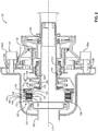
FIG. 2 is a schematic, cross-sectional side elevation view of the clutch assembly ofFIG. 1 , according to one or more examples of the subject matter, disclosed herein; -
FIG. 3 is a schematic, cross-sectional side elevation view of the clutch assembly ofFIG. 1 , according to one or more examples of the subject matter, disclosed herein; -
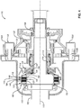
FIG. 4 is a schematic, cross-sectional side elevation view of the clutch assembly ofFIG. 1 , according to one or more examples of the subject matter, disclosed herein; -
FIG. 5 is a block diagram of aircraft production and service methodology; and -
FIG. 6 is a schematic illustration of an aircraft. - In
FIG. 1 , referred to above, solid lines, if any, connecting various elements and/or components may represent mechanical, electrical, fluid, optical, electromagnetic and other couplings and/or combinations thereof. As used herein, "coupled" means associated directly as well as indirectly. For example, a member A may be directly associated with a member B, or may be indirectly associated therewith, e.g., via another member C. It will be understood that not all relationships among the various disclosed elements are necessarily represented. Accordingly, couplings other than those depicted in the block diagrams may also exist. Dashed lines, if any, connecting blocks designating the various elements and/or components represent couplings similar in function and purpose to those represented by solid lines; however, couplings represented by the dashed lines may either be selectively provided or may relate to alternative examples of the subject matter, disclosed herein. Likewise, elements and/or components, if any, represented with dashed lines, indicate alternative examples of the subject matter, disclosed herein. One or more elements shown in solid and/or dashed lines may be omitted from a particular example without departing from the scope of the subject matter, disclosed herein. Environmental elements, if any, are represented with dotted lines. Virtual (imaginary) elements may also be shown for clarity. Those skilled in the art will appreciate that some of the features illustrated inFIG. 1 may be combined in various ways without the need to include other features described inFIG. 1 , other drawing figures, and/or the accompanying disclosure, even though such combination or combinations are not explicitly illustrated herein. Similarly, additional features not limited to the examples presented, may be combined with some or all of the features shown and described herein. - In the following description, numerous specific details are set forth to provide a thorough understanding of the disclosed concepts, which may be practiced without some or all of these particulars. In other instances, details of known devices and/or processes have been omitted to avoid unnecessarily obscuring the disclosure. While some concepts will be described in conjunction with specific examples, it will be understood that these examples are not intended to be limiting.
- Unless otherwise indicated, the terms "first," "second," etc. are used herein merely as labels, and are not intended to impose ordinal, positional, or hierarchical requirements on the items to which these terms refer. Moreover, reference to, e.g., a "second" item does not require or preclude the existence of, e.g., a "first" or lower-numbered item, and/or, e.g., a "third" or higher-numbered item.
- Reference herein to "one or more examples" means that one or more feature, structure, or characteristic described in connection with the example is included in at least one implementation. The phrase "one or more examples" in various places in the specification may or may not be referring to the same example.
- As used herein, a system, apparatus, structure, article, element, component, or hardware "configured to" perform a specified function is indeed capable of performing the specified function without any alteration, rather than merely having potential to perform the specified function after further modification. In other words, the system, apparatus, structure, article, element, component, or hardware "configured to" perform a specified function is specifically selected, created, implemented, utilized, programmed, and/or designed for the purpose of performing the specified function. As used herein, "configured to" denotes existing characteristics of a system, apparatus, structure, article, element, component, or hardware which enable the system, apparatus, structure, article, element, component, or hardware to perform the specified function without further modification. For purposes of this disclosure, a system, apparatus, structure, article, element, component, or hardware described as being "configured to" perform a particular function may additionally or alternatively be described as being "adapted to" and/or as being "operative to" perform that function.
- Illustrative, non-exhaustive examples, of the subject matter, disclosed herein, are provided below.
- Referring generally to
FIG. 1 and particularly to, e.g.,FIGS. 2-4 for illustrative purposes only and not by way of limitation, the following portion of this paragraph delineates a first example of the subject matter disclosed herein. According to the firstexample clutch assembly 110 comprisesinput shaft 102, havingcentral axis 172.Clutch assembly 110 also comprisesoutput shaft 104, co-axially arranged relative toinput shaft 102.Clutch assembly 110 further comprisesinput clutch drum 112, comprisingexternal splines 116. Inputclutch drum 112 is fixed to inputshaft 102 so that inputclutch drum 112 is neither rotatable nor translatable relative to inputshaft 102.Clutch assembly 110 additionally comprises outputclutch drum 114, comprisinginternal splines 118. Outputclutch drum 114 is selectively translatable relative tooutput shaft 104 and is not rotatable relative tooutput shaft 104.Clutch assembly 110 further comprisesclutch pack 122.Clutch pack 122 comprisesfirst plates 140, selectively translatable relative to inputshaft 102 and not rotatable relative to inputshaft 102.Clutch pack 122 also comprisessecond plates 142, selectively translatable relative tooutput shaft 104 and not rotatable relative tooutput shaft 104.Clutch assembly 110 also comprisesclutch piston 120, not rotatable relative tooutput shaft 104 and selectively translatable relative tooutput shaft 104 between, inclusively, a frictionally disengaged clutch-pack position and a frictionally engaged clutch-pack position.Clutch assembly 110 additionally comprises clutch-pack engagement spring 124, interposed between outputclutch drum 114 andclutch piston 120. Outputclutch drum 114 is selectively translatable relative to inputclutch drum 112 between, inclusively, a fully disengaged position, in whichinternal splines 118 of outputclutch drum 114 are not in mesh withexternal splines 116 of inputclutch drum 112 andfirst plates 140 ofclutch pack 122 are not frictionally coupled withsecond plates 142 ofclutch pack 122, and, inclusively, a positively engaged position, in whichinternal splines 118 of outputclutch drum 114 are in mesh withexternal splines 116 of inputclutch drum 112 andfirst plates 140 ofclutch pack 122 are frictionally coupled withsecond plates 142 ofclutch pack 122. Whenclutch piston 120 is in the frictionally disengaged clutch-pack position,first plates 140 ofclutch pack 122 are not frictionally coupled withsecond plates 142 ofclutch pack 122 andinternal splines 118 of outputclutch drum 114 are not in mesh withexternal splines 116 of inputclutch drum 112. Whenclutch piston 120 is in the frictionally engaged clutch-pack position,first plates 140 ofclutch pack 122 are frictionally coupled withsecond plates 142 ofclutch pack 122. -
Clutch assembly 110 provides for engagement and disengagement of torque transmission frominput shaft 102 tooutput shaft 104. Frictional coupling betweenfirst plates 140 andsecond plates 142 ofclutch pack 122, whenclutch piston 120 is in the frictionally engaged clutch-pack position, provides for transmitting relatively low torque frominput shaft 102 tooutput shaft 104. Meshing ofinternal splines 118 of outputclutch drum 114 withexternal splines 116 of inputclutch drum 112, when outputclutch drum 114 is in the positively engaged position, provides for transmitting relatively high torque frominput shaft 102 tooutput shaft 104. Accordingly, frictional coupling betweenfirst plates 140 andsecond plates 142 provides rotational synchronization betweeninput shaft 102 andoutput shaft 104 in preparation for meshing ofinternal splines 118 of outputclutch drum 114 withexternal splines 116 of inputclutch drum 112. Clutch-pack engagement spring 124 facilitates positioningclutch piston 120 in the frictionally engaged clutch-pack position before outputclutch drum 114 is translated to the positively engaged position as outputclutch drum 114 is selectively translated from the fully disengaged position to the positively engaged position. - In one or more examples,
external splines 116 of inputclutch drum 112 andinternal splines 118 of outputclutch drum 114 each include a leading engagement edge that is oblique relative tocentral axis 172 ofinput shaft 102. The leading engagement edges ofexternal splines 116 andinternal splines 118, being oblique relative tocentral axis 172, provide overlapping betweenexternal splines 116 andinternal splines 118, along plane perpendicular tocentral axis 172, beforeexternal splines 116 andinternal splines 118 mesh. Accordingly, the leading engagement edges ofexternal splines 116 andinternal splines 118, being oblique relative tocentral axis 172, help to increase the surface area ofexternal splines 116 andinternal splines 118 that contact each other asexternal splines 116 andinternal splines 118 initiate meshing engagement, which promotes longevity and durability ofexternal splines 116 andinternal splines 118. - According to one or more examples,
input shaft 102 is driven by a torque generator, such as an internal combustion engine, andoutput shaft 104 is coupled with a torque absorber, such as an aircraft rotor, so that the torque absorber receives torque generated by the torque absorber when outputclutch drum 114 is in the positively engaged position and/orclutch piston 120 is in the frictionally engaged clutch-pack position. - Referring generally to
FIG. 1 and particularly to, e.g.,FIG. 2 for illustrative purposes only and not by way of limitation, the following portion of this paragraph delineates a second example of the subject matter, disclosed herein. The second example encompassesclutch assembly 110 according to the first example, above, wherein, when outputclutch drum 114 is in the fully disengaged position relative to inputclutch drum 112,clutch piston 120 is in the frictionally disengaged clutch-pack position. -
Clutch piston 120, being in the frictionally disengaged clutch-pack position when outputclutch drum 114 is in the fully disengaged position, enables relative rotation betweeninput shaft 102 andoutput shaft 104, which disables transmission of torque frominput shaft 102 tooutput shaft 104. - Referring generally to
FIG. 1 and particularly to, e.g.,FIG. 4 for illustrative purposes only and not by way of limitation, the following portion of this paragraph delineates a third example of the subject matter, disclosed herein. The third example encompassesclutch assembly 110 according to the second example, above, wherein, when outputclutch drum 114 is in the positively engaged position relative to inputclutch drum 112, clutch-pack engagement spring 124 is compressed between outputclutch drum 114 andclutch piston 120, andclutch piston 120 is in the frictionally engaged clutch-pack position. - Compression of clutch-
pack engagement spring 124 between outputclutch drum 114 andclutch piston 120 provides for applying a biasing force toclutch piston 120 such thatclutch piston 120 translates from the frictionally disengaged clutch-pack position to the frictionally engaged clutch-pack position. Translating outputclutch drum 114, from the fully disengaged position, towardclutch piston 120 facilitates compression of clutch-pack engagement spring 124 between outputclutch drum 114 andclutch piston 120. - Referring generally to
FIG. 1 and particularly to, e.g.,FIG. 3 for illustrative purposes only and not by way of limitation, the following portion of this paragraph delineates a fourth example of the subject matter, disclosed herein. The fourth example encompassesclutch assembly 110 according to the third example, above, wherein outputclutch drum 114 is selectively translatable relative to inputclutch drum 112 into an intermediate position between the fully disengaged position relative to inputclutch drum 112 and the positively engaged position relative to inputclutch drum 112. When outputclutch drum 114 is in the intermediate position,internal splines 118 of outputclutch drum 114 are not in mesh withexternal splines 116 of inputclutch drum 112, andclutch piston 120 is in the frictionally engaged clutch-pack position. - Output
clutch drum 114, being in the intermediate position relative to inputclutch drum 112, enables co-rotation ofinput shaft 102 andoutput shaft 104 for relatively low torque values and enables relative rotation ofinput shaft 102 andoutput shaft 104 for relatively high torque values. Accordingly, outputclutch drum 114, being in the intermediate position relative to inputclutch drum 112, enables rotational synchronization betweeninput shaft 102 andoutput shaft 104 before meshing ofinternal splines 118 of outputclutch drum 114 withexternal splines 116 of inputclutch drum 112. The relatively low torque values are lower than the relatively high torque values. - Referring generally to
FIG. 1 and particularly to, e.g.,FIGS. 3 and4 for illustrative purposes only and not by way of limitation, the following portion of this paragraph delineates a fifth example of the subject matter, disclosed herein. The fifth example encompassesclutch assembly 110 according to the fourth example, above, wherein, when outputclutch drum 114 is in the intermediate position, clutch-pack engagement spring 124 is compressed a first amount between outputclutch drum 114 andclutch piston 120. When outputclutch drum 114 is in the positively engaged position relative to inputclutch drum 112, clutch-pack engagement spring 124 is compressed a second amount between outputclutch drum 114 andclutch piston 120. The second amount is greater than the first amount. - Compression of clutch-
pack engagement spring 124 from the first amount to the second amount enables outputclutch drum 114 to translate from the intermediate position to the positively engaged position. - Referring generally to
FIG. 1 and particularly to, e.g.,FIGS. 3 and4 for illustrative purposes only and not by way of limitation, the following portion of this paragraph delineates a sixth example of the subject matter, disclosed herein. The sixth example encompassesclutch assembly 110 according to the fourth or the fifth example, above, whereinclutch piston 120 is in the frictionally engaged clutch-pack position when outputclutch drum 114 is between, inclusively, the intermediate position relative to inputclutch drum 112 and, inclusively, the positively engaged position relative to inputclutch drum 112. -
Clutch piston 120, being in the frictionally engaged clutch-pack position when outputclutch drum 114 is between, inclusively, the intermediate position relative to inputclutch drum 112 and, inclusively, the positively engaged position relative to inputclutch drum 112, facilitates rotational synchronization betweeninput shaft 102 andoutput shaft 104 as outputclutch drum 114 translates from the positively engaged position to the intermediate position. Maintaining rotational synchronization betweeninput shaft 102 andoutput shaft 104 as outputclutch drum 114 translates from the positively engaged position toward the intermediate position promotes torsional damping betweeninput shaft 102 andoutput shaft 104 and responsive transitioning of outputclutch drum 114 back into the positively engaged position if necessary. - Referring generally to
FIG. 1 and particularly to, e.g.,FIG. 2 for illustrative purposes only and not by way of limitation, the following portion of this paragraph delineates a seventh example of the subject matter, disclosed herein. The seventh example encompassesclutch assembly 110 according to any one of the fourth to the sixth examples, above, whereinclutch piston 120 is in the frictionally disengaged clutch-pack position when outputclutch drum 114 is between, exclusively, the intermediate position relative to inputclutch drum 112 and, inclusively, the fully disengaged position relative to inputclutch drum 112. -
Clutch piston 120, being in the frictionally disengaged clutch-pack position when outputclutch drum 114 is between, exclusively, the intermediate position relative to inputclutch drum 112 and, inclusively, the fully disengaged position relative to inputclutch drum 112, enables relative rotation betweeninput shaft 102 andoutput shaft 104 as outputclutch drum 114 translates between, exclusively, the intermediate position and, inclusively, the fully disengaged position. - Referring generally to
FIG. 1 and particularly to, e.g.,FIGS. 2-4 for illustrative purposes only and not by way of limitation, the following portion of this paragraph delineates an eighth example of the subject matter, disclosed herein. The eight example encompassesclutch assembly 110 according to any one of the first to the seventh examples, above, whereinclutch assembly 110 further compriseslinear actuator 130, operable to translate outputclutch drum 114 relative to inputclutch drum 112. -
Linear actuator 130 promotes translation of outputclutch drum 114 andclutch piston 120 with a single actuator, which helps to simplifyclutch assembly 110. - Referring generally to
FIG. 1 and particularly to, e.g.,FIGS. 2-4 for illustrative purposes only and not by way of limitation, the following portion of this paragraph delineates a ninth example of the subject matter, disclosed herein. The ninth example encompassesclutch assembly 110 according to the eighth example, above, whereinlinear actuator 130 comprisescarriage 132, selectively translatable relative tooutput shaft 104. Outputclutch drum 114 is not translatable relative tocarriage 132 and is rotatable relative tocarriage 132.Linear actuator 130 also comprises drivengear 131, selectively rotatable relative tocarriage 132 and coupled tocarriage 132 so that rotation of drivengear 131 relative tocarriage 132 translatescarriage 132 relative tooutput shaft 104.Linear actuator 130 further comprisesdrive gear 133A, in mesh with drivengear 131.Linear actuator 130 additionally comprisesmotor 160A, operable to rotatedrive gear 133A. -
Carriage 132 provides for translational movement of outputclutch drum 114 relative tooutput shaft 104 while enabling outputclutch drum 114 to rotate relative tocarriage 132.Driven gear 131,drive gear 133A, andmotor 160A provide for precise and reliable translational actuation ofcarriage 132. - In one or more examples, driven
gear 131 andcarriage 132 form a worm-gear assembly where drivengear 131 is the worm wheel andcarriage 132 is the worm. Accordingly, drivengear 131 meshes withcarriage 132 to translationally movecarriage 132 relative tooutput shaft 104. In one or more examples,drive gear 133A is a spur gear andmotor 160A is any one of an electrically powered motor, a pneumatically-powered motor, a hydraulically-powered motor, and the like. - Referring generally to
FIG. 1 and particularly to, e.g.,FIGS. 2-4 for illustrative purposes only and not by way of limitation, the following portion of this paragraph delineates a tenth example of the subject matter, disclosed herein. The tenth example encompassesclutch assembly 110 according to the ninth example, above, whereinlinear actuator 130 further comprisessecond drive gear 133B, in mesh with drivengear 131.Linear actuator 130 additionally comprisessecond motor 160B, operable to rotatesecond drive gear 133B. -
Driven gear 131,second drive gear 133B, andsecond motor 160B provide for precise and reliable translational actuation ofcarriage 132. - In one or more examples,
second drive gear 133B is a spur gear andsecond motor 160B is any one of an electrically powered motor, a pneumatically-powered motor, a hydraulically-powered motor, and the like.Second motor 160B is separate frommotor 160A and, in one or more examples, is independently operable relative tomotor 160A. - Referring generally to
FIG. 1 and particularly to, e.g.,FIGS. 2-4 for illustrative purposes only and not by way of limitation, the following portion of this paragraph delineates a eleventh example of the subject matter, disclosed herein. The eleventh example encompassesclutch assembly 110 according to the tenth example, above, whereinmotor 160A is selectively operable to rotatedrive gear 133A so that drivengear 131 is rotated in a first rotational direction andcarriage 132 is translated relative tooutput shaft 104 in a first direction alongcentral axis 172 and is selectively operable to rotatedrive gear 133A so that drivengear 131 is rotated in a second rotational direction andcarriage 132 is translated relative tooutput shaft 104 in a second direction alongcentral axis 172.Second motor 160B is selectively operable to rotatesecond drive gear 133B so that drivengear 131 is rotated in the first rotational direction andcarriage 132 is translated relative tooutput shaft 104 in the first direction alongcentral axis 172 and is selectively operable to rotatesecond drive gear 133B so that drivengear 131 is rotated in the second rotational direction andcarriage 132 is translated relative tooutput shaft 104 in the second direction alongcentral axis 172. The first rotational direction and the second rotational direction are opposite to each other. The first direction and the second direction are opposite to each other.Motor 160A andsecond motor 160B are only operable synchronously with each other. - Synchronous operation of
motor 160A andsecond motor 160B to enable rotation of drivengear 131 in the first rotational direction and the second operational direction promote the use of two smaller motors rather than one large motor, which helps to reduce the size ofclutch assembly 110. Additionally, synchronous operation ofmotor 160A andsecond motor 160B to enable rotation of drivengear 131 in the first rotational direction and the second operational direction provides counterbalancing forces acting on drivengear 131, which can help with stability of drivengear 131. - Each of
motor 160A andsecond motor 160B can be a bidirectional motor. - Referring generally to
FIG. 1 and particularly to, e.g.,FIGS. 2-4 for illustrative purposes only and not by way of limitation, the following portion of this paragraph delineates a twelfth example of the subject matter, disclosed herein. The twelfth example encompassesclutch assembly 110 according to the tenth example, above, whereinmotor 160A is operable to rotatedrive gear 133A so that drivengear 131 is rotated in a first rotational direction andcarriage 132 is translated relative tooutput shaft 104 in a first direction alongcentral axis 172.Second motor 160B is operable to rotatesecond drive gear 133B so that drivengear 131 is rotated in a second rotational direction andcarriage 132 is translated relative tooutput shaft 104 in a second direction alongcentral axis 172. The first rotational direction and the second rotational direction are opposite to each other. The first direction and the second direction are opposite to each other.Motor 160A andsecond motor 160B are only operable asynchronously with each other. - Asynchronous operation of
motor 160A to enable rotation of drivengear 131 in the first rotational direction andsecond motor 160B to enable rotation of drivengear 131 in the second operational direction help reduce complexity in the controls and type of motors used formotor 160A andsecond motor 160B. - Each of
motor 160A andsecond motor 160B can be a unidirectional motor. - Referring generally to
FIG. 1 and particularly to, e.g.,FIGS. 2-4 for illustrative purposes only and not by way of limitation, the following portion of this paragraph delineates a thirteenth example of the subject matter, disclosed herein. The thirteenth example encompassesclutch assembly 110 according to the tenth example, above, wherein, whensecond motor 160B is disabled,motor 160A is selectively operable to rotatedrive gear 133A so that drivengear 131 is rotated in a first rotational direction andcarriage 132 is translated relative tooutput shaft 104 in a first direction alongcentral axis 172. Additionally, whensecond motor 160B is disabled,motor 160A is selectively operable to rotatedrive gear 133A so that drivengear 131 is rotated in a second rotational direction andcarriage 132 is translated relative tooutput shaft 104 in a second direction alongcentral axis 172. Furthermore, whensecond motor 160B is disabled, the first rotational direction and the second rotational direction are opposite to each other, and the first direction and the second direction are opposite to each other. -
Motor 160A, being selectively operable to rotatedrive gear 133A so that drivengear 131 is rotated in the first rotational direction and to rotatedrive gear 133A so that drivengear 131 is rotated in the second rotational direction whensecond motor 160B is disabled, provides redundancy in operation ofclutch assembly 110, which helps to promote reliability ofclutch assembly 110. - In one or more examples,
second motor 160B is selectively operable to rotatesecond drive gear 133B so that drivengear 131 is rotated in the first rotational direction andcarriage 132 is translated relative tooutput shaft 104 in the first direction alongcentral axis 172 and to rotatesecond drive gear 133B so that drivengear 131 is rotated in the second rotational direction andcarriage 132 is translated relative tooutput shaft 104 in the second direction alongcentral axis 172 whenmotor 160A is disabled. - Referring generally to
FIG. 1 and particularly to, e.g.,FIGS. 2-4 for illustrative purposes only and not by way of limitation, the following portion of this paragraph delineates a fourteenth example of the subject matter, disclosed herein. The fourteenth example encompassesclutch assembly 110 according to the thirteenth example, above, whereinmotor 160A is operated so that drivengear 131 is rotated bydrive gear 133A in either the first rotational direction or in the second rotational direction.Second drive gear 133B is rotated by drivengear 131. Drivegear 133A andsecond drive gear 133B rotate in identical directions. -
Second drive gear 133B, being rotated by drivengear 131, promotes freewheeling ofsecond drive gear 133B asmotor 160A is operated to rotatedrive gear 133A and drivengear 131. - Referring generally to
FIG. 1 and particularly to, e.g.,FIGS. 2-4 for illustrative purposes only and not by way of limitation, the following portion of this paragraph delineates a fifteenth example of the subject matter, disclosed herein. The fifteenth example encompassesclutch assembly 110 according to any one of the tenth to the fourteenth examples, above, whereinclutch assembly 110 further comprises bearing 134, interposed betweencarriage 132 and outputclutch drum 114 and configured to enable rotation ofcarriage 132 relative to outputclutch drum 114. - Bearing 134 helps to reduce friction between
carriage 132 and outputclutch drum 114 as outputclutch drum 114 rotates relative tocarriage 132. - In one or more examples, bearing 134 is a duplex bearing set.
- Referring generally to
FIG. 1 and particularly to, e.g.,FIGS. 2-4 for illustrative purposes only and not by way of limitation, the following portion of this paragraph delineates a sixteenth example of the subject matter, disclosed herein. The sixteenth example encompassesclutch assembly 110 according to any one of the eighth to the fifteenth examples, above, whereinlinear actuator 130 is selectively operable to translate outputclutch drum 114 between, inclusively, the fully disengaged position relative to inputclutch drum 112 and, inclusively, the positively engaged position relative to inputclutch drum 112. -
Linear actuator 130 promotes translation of outputclutch drum 114 between, inclusively, the fully disengaged position relative to inputclutch drum 112 and, inclusively, the positively engaged position relative to inputclutch drum 112 with a single actuator, which helps to simplifyclutch assembly 110. - Referring generally to
FIG. 1 and particularly to, e.g.,FIGS. 2-4 for illustrative purposes only and not by way of limitation, the following portion of this paragraph delineates a seventeenth example of the subject matter, disclosed herein. The seventeenth example encompassesclutch assembly 110 according to any one of the first to the sixteenth examples, above, wherein, when outputclutch drum 114 translates relative tooutput shaft 104 from the fully disengaged position relative to inputclutch drum 112 to the positively engaged position relative to inputclutch drum 112,clutch piston 120 translates relative tooutput shaft 104 from the frictionally disengaged clutch-pack position to the frictionally engaged clutch-pack position. -
Clutch piston 120, translating relative tooutput shaft 104 from the frictionally disengaged clutch-pack position to the frictionally engaged clutch-pack position when outputclutch drum 114 translates relative tooutput shaft 104 from the fully disengaged position relative to inputclutch drum 112 to the positively engaged position relative to inputclutch drum 112, promotes synchronization betweeninput shaft 102 andoutput shaft 104 beforeinternal splines 118 of outputclutch drum 114 mesh withexternal splines 116 of inputclutch drum 112. - Referring generally to
FIG. 1 and particularly to, e.g.,FIGS. 2-4 for illustrative purposes only and not by way of limitation, the following portion of this paragraph delineates an eighteenth example of the subject matter, disclosed herein. The eighteenth example encompassesclutch assembly 110 according to any one of the first to the seventeenth examples, above, whereinclutch assembly 110 further comprises clutch-pack disengagement spring 126, interposed betweenclutch piston 120 andoutput shaft 104 alongcentral axis 172 and configured to apply a first biasing force toclutch piston 120 in a first direction alongcentral axis 172. Clutch-pack engagement spring 124 is configured to apply a second biasing force toclutch piston 120 in a second direction alongcentral axis 172, opposite the first direction. - Clutch-
pack disengagement spring 126 facilitates positioning ofclutch piston 120 into the frictionally engaged clutch-pack position before outputclutch drum 114 is positioned into the positively engaged position by compressing to allowclutch piston 120 to translate into the frictionally engaged clutch-pack position under a predetermined biasing force from clutch-pack engagement spring 124. Additionally, clutch-pack disengagement spring 126 helps to frictionally decouplefirst plates 140 andsecond plates 142 ofclutch pack 122 when outputclutch drum 114 translates from the intermediate position toward the fully disengaged position by urgingclutch piston 120 from the frictionally engaged clutch-pack position to the frictionally disengaged clutch-pack position. - Referring generally to
FIG. 1 and particularly to, e.g.,FIGS. 2-4 for illustrative purposes only and not by way of limitation, the following portion of this paragraph delineates a nineteenth example of the subject matter, disclosed herein. The nineteenth example encompassesclutch assembly 110 according to the eighteenth example, above, wherein clutch-pack engagement spring 124 has a first spring constant. Clutch-pack disengagement spring 126 has a second spring constant. The first spring constant is different from the second spring constant. - The first spring constant of clutch-
pack engagement spring 124, being different from (e.g., greater than) the second spring constant of clutch-pack disengagement spring 126, provides for clutch-pack disengagement spring 126 compressing, to allowclutch piston 120 to translate into the frictionally engaged clutch-pack position, when a predetermined biasing force from clutch-pack engagement spring 124 is applied toclutch piston 120. - Referring generally to
FIG. 1 and particularly to, e.g.,FIGS. 2-4 for illustrative purposes only and not by way of limitation, the following portion of this paragraph delineates a twentieth example of the subject matter, disclosed herein. The twentieth example encompassesclutch assembly 110 according to the eighteenth or the nineteenth example, above, wherein, when outputclutch drum 114 is in the fully disengaged position relative to inputclutch drum 112, the first biasing force is greater than the second biasing force. Whenclutch piston 120 is in the frictionally engaged clutch-pack position, the first biasing force is less than the second biasing force by a first amount. When outputclutch drum 114 is in the positively engaged position relative to inputclutch drum 112, the first biasing force is less than the second biasing force by a second amount. The first amount is less than the second amount. - The first biasing force, being greater than the second biasing force when output
clutch drum 114 is in the fully disengaged position, ensuresclutch piston 120 is in frictionally disengaged clutch-pack position. The first biasing force, being less than the second biasing force whenclutch piston 120 is in the frictionally engaged clutch-pack position and when outputclutch drum 114 is in the positively engaged position, ensuresclutch piston 120 is in frictionally engaged clutch-pack position. The first amount of difference between the first biasing force and the second biasing force, being less than the second amount of difference between the first biasing force and the second biasing force, provides for the further compression of clutch-pack engagement spring 124 by outputclutch drum 114 as outputclutch drum 114 translates from the intermediate position to the positively engaged position. - Referring generally to
FIG. 1 and particularly to, e.g.,FIGS. 2-4 for illustrative purposes only and not by way of limitation, the following portion of this paragraph delineates a twenty-first example of the subject matter, disclosed herein. The twenty-first example encompassesclutch assembly 110 according to any one of the eighteenth to the twentieth examples, above, wherein clutch-pack disengagement spring 126 is a first Belleville spring. Clutch-pack engagement spring 124 is a second Belleville spring. The first Belleville spring is different from the second Belleville spring. - Clutch-
pack disengagement spring 126, being a first Belleville spring, and clutch-pack engagement spring 124, being a second Belleville spring, provides for reliably transmitting concentric loads in a small installation space. The first Belleville spring, being different from the second Belleville spring, promotes a difference in the biasing forces, applied by the respective first Belleville spring and the second Belleville spring. - In one or more examples, each of the first Belleville spring and the second Belleville spring is a coned-disc spring, conical spring washer, disc spring, or cupped spring washer. Moreover, each of the first Belleville spring and the second Belleville spring can include one or multiple back-to-back washers.
- Referring generally to
FIG. 1 and particularly to, e.g.,FIGS. 2-4 for illustrative purposes only and not by way of limitation, the following portion of this paragraph delineates a twenty-second example of the subject matter, disclosed herein. The twenty-second example encompassesclutch assembly 110 according to any one of the eighteenth to the twenty-first examples, above, whereinclutch assembly 110 further comprises retainingring 128, which is not translatable relative tooutput shaft 104. Retainingring 128 prevents translational movement ofclutch piston 120 relative tooutput shaft 104 in the first direction alongcentral axis 172 whenclutch piston 120 is in the frictionally disengaged clutch-pack position. - Retaining
ring 128 helps keepclutch piston 120 close toclutch pack 122 whenclutch piston 120 is in the frictionally disengaged clutch-pack position, which promotes responsiveness ofclutch assembly 110. - Referring generally to
FIG. 1 and particularly to, e.g.,FIGS. 2-4 for illustrative purposes only and not by way of limitation, the following portion of this paragraph delineates a twenty-third example of the subject matter, disclosed herein. The twenty-third example encompassesclutch assembly 110 according to any one of the eighteenth to the twenty-first examples, above, whereininput shaft 102 comprises input-shaft hub 182, which comprises input-shaft-hub splines 184. Input-shaft-hub splines 184 are engaged withfirst plates 140 ofclutch pack 122 to prevent rotation offirst plates 140 relative to inputshaft 102.Output shaft 104 comprises output-shaft hub 150, which comprises output-shaft-hub splines 152. Output-shaft-hub splines 152 are engaged withsecond plates 142 ofclutch pack 122 to prevent rotation ofsecond plates 142 relative to outputclutch drum 114. Clutch-pack disengagement spring 126 is interposed betweenclutch piston 120 and output-shaft hub 150 ofoutput shaft 104. -
First plates 140, being engaged with input-shaft-hub splines 184, andsecond plates 142, being engaged with output-shaft-hub splines 152, facilitate co-rotation ofinput shaft 102 andoutput shaft 104 whenfirst plates 140 are frictionally coupled withsecond plates 142. - Referring generally to
FIG. 1 and particularly to, e.g.,FIG. 2 for illustrative purposes only and not by way of limitation, the following portion of this paragraph delineates a twenty-fourth example of the subject matter, disclosed herein. The twenty-fourth example encompassesclutch assembly 110 according to any one of the eighteenth to the twenty-third examples, above, wherein, when outputclutch drum 114 is in the fully disengaged position relative to inputclutch drum 112, a force, applied to outputclutch drum 114 by clutch-pack engagement spring 124 alongcentral axis 172 is less than a force, applied to outputclutch drum 114 by clutch-pack disengagement spring 126 alongcentral axis 172. - The force, applied to output
clutch drum 114 by clutch-pack engagement spring 124, being less than the force, applied to outputclutch drum 114 by clutch-pack disengagement spring 126, when outputclutch drum 114 is in the fully disengaged position, provides for preventing outputclutch drum 114 from translating out of fully disengaged position. - Referring generally to
FIG. 1 and particularly to, e.g.,FIGS. 2-4 for illustrative purposes only and not by way of limitation, the following portion of this paragraph delineates a twenty-fifth example of the subject matter, disclosed herein. The twenty-fifth example encompassesclutch assembly 110 according to any one of the first to the twenty-fourth examples, above, wherein clutch-pack engagement spring 124 is within outputclutch drum 114. - Clutch-
pack engagement spring 124, being within outputclutch drum 114, provides for the reduction in the overall size ofclutch assembly 110 by utilizing space within outputclutch drum 114 for placement of components. Additionally, clutch-pack engagement spring 124, being within outputclutch drum 114, helps protect and shield clutch-pack engagement spring 124. - Referring generally to
FIG. 1 and particularly to, e.g.,FIGS. 2-4 for illustrative purposes only and not by way of limitation, the following portion of this paragraph delineates a twenty-sixth example of the subject matter, disclosed herein. The twenty-sixth example encompassesclutch assembly 110 according to any one of the first to the twenty-fifth examples, above, wherein outputclutch drum 114 is slidable relative tooutput shaft 104 alongcentral axis 172 and is in direct contact withoutput shaft 104. - Output
clutch drum 114, being slidable relative tooutput shaft 104 and in direct contact withoutput shaft 104, promotes co-rotational coupling between outputclutch drum 114 andoutput shaft 104. - Referring generally to
FIG. 1 and particularly to, e.g.,FIGS. 2-4 for illustrative purposes only and not by way of limitation, the following portion of this paragraph delineates a twenty-seventh example of the subject matter, disclosed herein. The twenty-seventh example encompassesclutch assembly 110 according to any one of the first to the twenty-sixth examples, above, whereinclutch piston 120 is selectively movable relative tooutput shaft 104 alongcentral axis 172 and is in direct contact withoutput shaft 104. -
Clutch piston 120, being selectively movable relative tooutput shaft 104 and in direct contact withoutput shaft 104, promotes co-rotational coupling betweenclutch piston 120 andoutput shaft 104. - In one or more examples,
output shaft 104 includes splines that engage corresponding splines onclutch piston 120 to facilitate translational movement ofclutch piston 120 relative tooutput shaft 104 and co-rotation ofclutch piston 120 andoutput shaft 104. - Referring generally to
FIG. 1 and particularly to, e.g.,FIGS. 2-4 for illustrative purposes only and not by way of limitation, the following portion of this paragraph delineates a twenty-eighth example of the subject matter, disclosed herein. The twenty-eighth example encompassesclutch assembly 110 according to any one of the first to the twenty-seventh examples, above, whereinclutch assembly 110 further comprises input-output bearing 170, interposed betweeninput shaft 102 andoutput shaft 104 and configured to enable relative rotational motion betweeninput shaft 102 andoutput shaft 104 when outputclutch drum 114 is in the fully disengaged position relative to inputclutch drum 112. - Input-
output bearing 170 promotes relative rotational motion, aboutcentral axis 172, betweeninput shaft 102 andoutput shaft 104 when outputclutch drum 114 is in the fully disengaged position by reducing friction betweeninput shaft 102 andoutput shaft 104. In one or more examples, input-output bearing 170 engagesoutput shaft 104 at an input end ofoutput shaft 104, such thatclutch pack 122 is interposed between input-output bearing 170 and outputclutch drum 114, to promote concentricity ofoutput shaft 104 relative to inputshaft 102. - Referring generally to
FIG. 1 and particularly to, e.g.,FIGS. 2-4 for illustrative purposes only and not by way of limitation, the following portion of this paragraph delineates a twenty-ninth example of the subject matter, disclosed herein. The twenty-ninth example encompassesclutch assembly 110 according to the twenty-eighth example, above, whereininput shaft 102 overlapsoutput shaft 104 alongcentral axis 172 ofinput shaft 102 to define an overlapping region betweeninput shaft 102 andoutput shaft 104. Input-output bearing 170 is located within the overlapping region. - Input-
output bearing 170, being located within the overlapping region, promotes concentricity ofoutput shaft 104 relative to inputshaft 102. - Referring generally to
FIG. 1 and particularly to, e.g.,FIGS. 2-4 for illustrative purposes only and not by way of limitation, the following portion of this paragraph delineates a thirtieth example of the subject matter, disclosed herein. The thirtieth example encompassesclutch assembly 110 according to any one of the first to the twenty-ninth examples, above, whereinoutput shaft 104 comprises output-shaft splines 174. Outputclutch drum 114 comprises output-clutch-drum splines 176. Output-shaft splines 174 and output-clutch-drum splines 176 mesh to prevent rotation of outputclutch drum 114 relative tooutput shaft 104 and to enable translational movement of outputclutch drum 114 relative tooutput shaft 104 alongcentral axis 172. - Meshing of output-
shaft splines 174 and output-clutch-drum splines 176 provides robust mechanical co-rotational and translatable coupling betweenoutput shaft 104 and outputclutch drum 114. - Examples of the subject matter, disclosed herein may be described in the context of aircraft manufacturing and
service method 1100 as shown inFIG. 5 andaircraft 1102 as shown inFIG. 6 . During pre-production,illustrative method 1100 may include specification and design (block 1104) ofaircraft 1102 and material procurement (block 1106). During production, component and subassembly manufacturing (block 1108) and system integration (block 1110) ofaircraft 1102 may take place. Thereafter,aircraft 1102 may go through certification and delivery (block 1112) to be placed in service (block 1114). While in service,aircraft 1102 may be scheduled for routine maintenance and service (block 1116). Routine maintenance and service may include modification, reconfiguration, refurbishment, etc. of one or more systems ofaircraft 1102. - Each of the processes of
illustrative method 1100 may be performed or carried out by a system integrator, a third party, and/or an operator (e.g., a customer). For the purposes of this description, a system integrator may include, without limitation, any number of aircraft manufacturers and major-system subcontractors; a third party may include, without limitation, any number of vendors, subcontractors, and suppliers; and an operator may be an airline, leasing company, military entity, service organization, and so on. - As shown in
FIG. 6 ,aircraft 1102 produced byillustrative method 1100 may includeairframe 1118 with a plurality of high-level systems 1120 and interior 1122. Examples of high-level systems 1120 include one or more ofpropulsion system 1124,electrical system 1126,hydraulic system 1128, andenvironmental system 1130. Any number of other systems may be included. Although an aerospace example is shown, the principles disclosed herein may be applied to other industries, such as the automotive industry. Accordingly, in addition toaircraft 1102, the principles disclosed herein may apply to other vehicles, e.g., land vehicles, marine vehicles, space vehicles, etc. - Apparatus(es) and method(s) shown or described herein may be employed during any one or more of the stages of the manufacturing and
service method 1100. For example, components or subassemblies corresponding to component and subassembly manufacturing (block 1108) may be fabricated or manufactured in a manner similar to components or subassemblies produced whileaircraft 1102 is in service (block 1114). Also, one or more examples of the apparatus(es), method(s), or combination thereof may be utilized duringproduction stages aircraft 1102. Similarly, one or more examples of the apparatus or method realizations, or a combination thereof, may be utilized, for example and without limitation, whileaircraft 1102 is in service (block 1114) and/or during maintenance and service (block 1116). - Also disclosed herein are the following illustrative, non-exhaustive examples, which relate to:
- A clutch assembly 110, comprising: an input shaft 102, having a central axis 172; an output shaft 104, co-axially arranged relative to the input shaft 102; an input clutch drum 112, comprising external splines 116, and wherein the input clutch drum 112 is fixed to the input shaft 102 so that the input clutch drum 112 is neither rotatable nor translatable relative to the input shaft 102; an output clutch drum 114, comprising internal splines 118, and wherein the output clutch drum 114 is selectively translatable relative to the output shaft 104 and is not rotatable relative to the output shaft 104; a clutch pack 122, comprising: first plates 140, selectively translatable relative to the input shaft 102 and not rotatable relative to the input shaft 102; and second plates 142, selectively translatable relative to the output shaft 104 and not rotatable relative to the output shaft 104; a clutch piston 120, not rotatable relative to the output shaft 104 and selectively translatable relative to the output shaft 104 between, inclusively, a frictionally disengaged clutch-pack position and a frictionally engaged clutch-pack position; and a clutch-pack engagement spring 124, interposed between the output clutch drum 114 and the clutch piston 120; and wherein: the output clutch drum 114 is selectively translatable relative to the input clutch drum 112 between, inclusively, a fully disengaged position, in which the internal splines 118 of the output clutch drum 114 are not in mesh with the external splines 116 of the input clutch drum 112 and the first plates 140 of the clutch pack 122 are not frictionally coupled with the second plates 142 of the clutch pack 122, and, inclusively, a positively engaged position, in which the internal splines 118 of the output clutch drum 114 are in mesh with the external splines 116 of the input clutch drum 112 and the first plates 140 of the clutch pack 122 are frictionally coupled with the second plates 142 of the clutch pack 122; when the clutch piston 120 is in the frictionally disengaged clutch-pack position, the first plates 140 of the clutch pack 122 are not frictionally coupled with the second plates 142 of the clutch pack 122 and the internal splines 118 of the output clutch drum 114 are not in mesh with the external splines of the input clutch drum 112; and when the clutch piston 120 is in the frictionally engaged clutch-pack position, the first plates 140 of the clutch pack 122 are frictionally coupled with the second plates 142 of the clutch pack 122.
- The
clutch assembly 110 described in the immediately preceding paragraph, wherein, when the outputclutch drum 114 is in the fully disengaged position relative to the inputclutch drum 112, theclutch piston 120 is in the frictionally disengaged clutch-pack position. - The
clutch assembly 110 described in the immediately preceding paragraph, wherein, when the outputclutch drum 114 is in the positively engaged position relative to the inputclutch drum 112, the clutch-pack engagement spring 124 is compressed between the outputclutch drum 114 and theclutch piston 120, and theclutch piston 120 is in the frictionally engaged clutch-pack position. - The
clutch assembly 110 described in the immediately preceding paragraph, wherein: the outputclutch drum 114 is selectively translatable relative to the inputclutch drum 112 into an intermediate position between the fully disengaged position relative to the inputclutch drum 112 and the positively engaged position relative to the inputclutch drum 112; and when the outputclutch drum 114 is in the intermediate position: theinternal splines 118 of the outputclutch drum 114 are not in mesh with theexternal splines 116 of the inputclutch drum 112; and theclutch piston 120 is in the frictionally engaged clutch-pack position. - The
clutch assembly 110 described in the immediately preceding paragraph, wherein: when the outputclutch drum 114 is in the intermediate position, the clutch-pack engagement spring 124 is compressed a first amount between the outputclutch drum 114 and theclutch piston 120; when the outputclutch drum 114 is in the positively engaged position relative to the inputclutch drum 112, the clutch-pack engagement spring 124 is compressed a second amount between the outputclutch drum 114 and theclutch piston 120; and the second amount is greater than the first amount. - The
clutch assembly 110 described in any one of the two immediately preceding paragraphs, wherein theclutch piston 120 is in the frictionally engaged clutch-pack position when the outputclutch drum 114 is between, inclusively, the intermediate position relative to the inputclutch drum 112 and, inclusively, the positively engaged position relative to the inputclutch drum 112. - The
clutch assembly 110 described in any one of the three immediately preceding paragraphs, wherein, theclutch piston 120 is in the frictionally disengaged clutch-pack position when the outputclutch drum 114 is between, exclusively, the intermediate position relative to the inputclutch drum 112 and, inclusively, the fully disengaged position relative to the inputclutch drum 112. - The
clutch assembly 110 described in any one of the seven immediately preceding paragraphs, further comprising alinear actuator 130, operable to translate the outputclutch drum 114 relative to the inputclutch drum 112. - The
clutch assembly 110 described in the immediately preceding paragraph, wherein thelinear actuator 130 comprises: acarriage 132, selectively translatable relative to theoutput shaft 104 and wherein the outputclutch drum 114 is not translatable relative to thecarriage 132 and is rotatable relative to thecarriage 132; a drivengear 131, selectively rotatable relative to thecarriage 132 and coupled to thecarriage 132 so that rotation of the drivengear 131 relative to thecarriage 132 translates thecarriage 132 relative to theoutput shaft 104; adrive gear 133A, in mesh with the drivengear 131; and amotor 160A, operable to rotate thedrive gear 133A. - The
clutch assembly 110 described in the immediately preceding paragraph, wherein thelinear actuator 130 further comprises: asecond drive gear 133B, in mesh with the drivengear 131; and asecond motor 160B, operable to rotate thesecond drive gear 133B. - The
clutch assembly 110 described in the immediately preceding paragraph, wherein themotor 160A is selectively operable to: rotate thedrive gear 133A so that the drivengear 131 is rotated in a first rotational direction and thecarriage 132 is translated relative to theoutput shaft 104 in a first direction along thecentral axis 172; and rotate thedrive gear 133A so that the drivengear 131 is rotated in a second rotational direction and thecarriage 132 is translated relative to theoutput shaft 104 in a second direction along thecentral axis 172; thesecond motor 160B is selectively operable to: rotate thesecond drive gear 133B so that the drivengear 131 is rotated in the first rotational direction and thecarriage 132 is translated relative to theoutput shaft 104 in the first direction along thecentral axis 172; and rotate thesecond drive gear 133B so that the drivengear 131 is rotated in the second rotational direction and thecarriage 132 is translated relative to theoutput shaft 104 in the second direction along thecentral axis 172;
the first rotational direction and the second rotational direction are opposite to each other;
the first direction and the second direction are opposite to each other; and themotor 160A and thesecond motor 160B are only operable synchronously with each other. - The
clutch assembly 110 described in the tenth one of the eleven immediately preceding paragraphs, wherein: themotor 160A is operable to rotate thedrive gear 133A so that the drivengear 131 is rotated in a first rotational direction and thecarriage 132 is translated relative to theoutput shaft 104 in a first direction along thecentral axis 172; thesecond motor 160B is operable to rotate thesecond drive gear 133B so that the drivengear 131 is rotated in a second rotational direction and thecarriage 132 is translated relative to theoutput shaft 104 in a second direction along thecentral axis 172; the first rotational direction and the second rotational direction are opposite to each other; the first direction and the second direction are opposite to each other; and
themotor 160A and thesecond motor 160B are only operable asynchronously with each other. - The
clutch assembly 110 described in the tenth one of the twelve immediately preceding paragraphs, wherein, when thesecond motor 160B is disabled: themotor 160A is selectively operable to rotate thedrive gear 133A so that the drivengear 131 is rotated in a first rotational direction and thecarriage 132 is translated relative to theoutput shaft 104 in a first direction along thecentral axis 172; themotor 160A is selectively operable to rotate thedrive gear 133A so that the drivengear 131 is rotated in a second rotational direction and thecarriage 132 is translated relative to theoutput shaft 104 in a second direction along thecentral axis 172; the first rotational direction and the second rotational direction are opposite to each other; and the first direction and the second direction are opposite to each other. - The
clutch assembly 110 described in the immediately preceding paragraph, wherein: themotor 160A is operated so that the drivengear 131 is rotated by thedrive gear 133A in either the first rotational direction or in the second rotational direction; thesecond drive gear 133B is rotated by the drivengear 131; and thedrive gear 133A and thesecond drive gear 133B rotate in identical directions. - The
clutch assembly 110 described in any one of the tenth to the fourteenth of the fourteen immediately preceding paragraphs, further comprising abearing 134, interposed between thecarriage 132 and the outputclutch drum 114 and configured to enable rotation ofcarriage 132 relative to the outputclutch drum 114. - The
clutch assembly 110 described in any one of the eighth to the fifteenth of the fifteen immediately preceding paragraphs, wherein thelinear actuator 130 is selectively operable to translate the outputclutch drum 114 between, inclusively, the fully disengaged position relative to the inputclutch drum 112 and, inclusively, the positively engaged position relative to the inputclutch drum 112. - The
clutch assembly 110 described in any one of the sixteen immediately preceding paragraphs, wherein, when the outputclutch drum 114 translates relative to theoutput shaft 104 from the fully disengaged position relative to the inputclutch drum 112 to the positively engaged position relative to the inputclutch drum 112, theclutch piston 120 translates relative to theoutput shaft 104 from the frictionally disengaged clutch-pack position to the frictionally engaged clutch-pack position. - The
clutch assembly 110 described in any one of the seventeen immediately preceding paragraphs, further comprising a clutch-pack disengagement spring 126, interposed between theclutch piston 120 and theoutput shaft 104 along thecentral axis 172 and configured to apply a first biasing force to theclutch piston 120 in a first direction along thecentral axis 172, and wherein the clutch-pack engagement spring 124 is configured to apply a second biasing force to theclutch piston 120 in a second direction along thecentral axis 172, opposite the first direction. - The
clutch assembly 110 described in the immediately preceding paragraph, wherein the clutch-pack engagement spring 124 has a first spring constant; the clutch-pack disengagement spring 126 has a second spring constant; and the first spring constant is different from the second spring constant. - The
clutch assembly 110 described in any one of the two immediately preceding paragraphs, wherein: when the outputclutch drum 114 is in the fully disengaged position relative to the inputclutch drum 112, the first biasing force is greater than the second biasing force; when theclutch piston 120 is in the frictionally engaged clutch-pack position, the first biasing force is less than the second biasing force by a first amount; when the outputclutch drum 114 is in the positively engaged position relative to the inputclutch drum 112, the first biasing force is less than the second biasing force by a second amount; and the first amount is less than the second amount. - The
clutch assembly 110 described in any one of the three immediately preceding paragraphs, wherein: the clutch-pack disengagement spring 126 is a first Belleville spring;
the clutch-pack engagement spring 124 is a second Belleville spring; and the first Belleville spring is different from the second Belleville spring. - The
clutch assembly 110 described in any one of the four immediately preceding paragraphs, further comprising a retainingring 128, which is not translatable relative to theoutput shaft 104, and wherein the retainingring 128 prevents translational movement of theclutch piston 120 relative to theoutput shaft 104 in the first direction along thecentral axis 172 when theclutch piston 120 is in the frictionally disengaged clutch-pack position. - The
clutch assembly 110 described in any one of the five immediately preceding paragraphs, wherein: theinput shaft 102 comprises an input-shaft hub 182, which comprises input-shaft-hub splines 184; the input-shaft-hub splines 184 are engaged with thefirst plates 140 of theclutch pack 122 to prevent rotation of thefirst plates 140 relative to theinput shaft 102; theoutput shaft 104 comprises an output-shaft hub 150, which comprises output-shaft-hub splines 152; the output-shaft-hub splines 152 are engaged with thesecond plates 142 of theclutch pack 122 to prevent rotation of thesecond plates 142 relative to the outputclutch drum 114; and the clutch-pack disengagement spring 126 is interposed between theclutch piston 120 and the output-shaft hub 150 of theoutput shaft 104. - The
clutch assembly 110 described in any one of the six immediately preceding paragraphs, wherein, when the outputclutch drum 114 is in the fully disengaged position relative to the inputclutch drum 112, a force, applied to the outputclutch drum 114 by the clutch-pack engagement spring 124 along thecentral axis 172 is less than a force, applied to the outputclutch drum 114 by the clutch-pack disengagement spring 126 along thecentral axis 172. - The
clutch assembly 110 described in any one of twenty four immediately preceding paragraphs, wherein the clutch-pack engagement spring 124 is within the output clutch drum (114). - The
clutch assembly 110 described in any one of the twenty five immediately preceding paragraphs, wherein the outputclutch drum 114 is slidable relative to theoutput shaft 104 along thecentral axis 172 and is in direct contact with theoutput shaft 104. - The
clutch assembly 110 described in any one of the twenty six immediately preceding paragraphs, wherein theclutch piston 120 is selectively movable relative to theoutput shaft 104 along thecentral axis 172 and is in direct contact with theoutput shaft 104. - The
clutch assembly 110 described in any one of the twenty seven immediately preceding paragraphs, further comprising an input-output bearing 170, interposed between theinput shaft 102 and theoutput shaft 104 and configured to enable relative rotational motion between theinput shaft 102 and theoutput shaft 104 when the outputclutch drum 114 is in the fully disengaged position relative to the inputclutch drum 112. - The
clutch assembly 110 described in the immediately preceding paragraph, wherein: theinput shaft 102 overlaps theoutput shaft 104 along thecentral axis 172 of theinput shaft 102 to define an overlapping region between theinput shaft 102 and theoutput shaft 104; and the input-output bearing 170 is located within the overlapping region. - The
clutch assembly 110 described in any one of the twenty nine immediately preceding paragraphs, wherein: theoutput shaft 104 comprises output-shaft splines 174; the outputclutch drum 114 comprises output-clutch-drum splines 176; and the output-shaft splines 174 and the output-clutch-drum splines 176 mesh to prevent rotation of the outputclutch drum 114 relative to theoutput shaft 104 and to enable translational movement of the outputclutch drum 114 relative to theoutput shaft 104 along thecentral axis 172. - Different examples of the apparatus(es) and method(s) disclosed herein include a variety of components, features, and functionalities. It should be understood that the various examples of the apparatus(es) and method(s) disclosed herein may include any of the components, features, and functionalities of any of the other examples of the apparatus(es) and method(s) disclosed herein in any combination, and all of such possibilities are intended to be within the scope of the present disclosure.
- Many modifications of examples, set forth herein, will come to mind to one skilled in the art, to which the present disclosure pertains, having the benefit of the teachings, presented in the foregoing descriptions and the associated drawings.
- Therefore, it is to be understood that the subject matter, disclosed herein, is not to be limited to the specific examples illustrated and that modifications and other examples are intended to be included within the scope of the appended claims. Moreover, although the foregoing description and the associated drawings describe examples of the subject matter, disclosed herein, in the context of certain illustrative combinations of elements and/or functions, it should be appreciated that different combinations of elements and/or functions may be provided by alternative implementations without departing from the scope of the appended claims. Accordingly, parenthetical reference numerals in the appended claims are presented for illustrative purposes only and are not intended to limit the scope of the claimed subject matter to the specific examples provided in the present disclosure.
Claims (15)
- A clutch assembly (110), comprising:an input shaft (102), having a central axis (172);an output shaft (104), co-axially arranged relative to the input shaft (102);an input clutch drum (112), comprising external splines (116), and wherein the input clutch drum (112) is fixed to the input shaft (102) so that the input clutch drum (112) is neither rotatable nor translatable relative to the input shaft (102);an output clutch drum (114), comprising internal splines (118), and wherein the output clutch drum (114) is selectively translatable relative to the output shaft (104) and is not rotatable relative to the output shaft (104);a clutch pack (122), comprising:first plates (140), selectively translatable relative to the input shaft (102) and not rotatable relative to the input shaft (102); andsecond plates (142), selectively translatable relative to the output shaft (104) andnot rotatable relative to the output shaft (104);a clutch piston (120), not rotatable relative to the output shaft (104) and selectively translatable relative to the output shaft (104) between, inclusively, a frictionally disengaged clutch-pack position and a frictionally engaged clutch-pack position; anda clutch-pack engagement spring (124), interposed between the output clutch drum (114) and the clutch piston (120); andwherein:the output clutch drum (114) is selectively translatable relative to the input clutch drum (112) between, inclusively, a fully disengaged position, in which the internal splines (118) of the output clutch drum (114) are not in mesh with the external splines (116) of the input clutch drum (112) and the first plates (140) of the clutch pack (122) are not frictionally coupled with the second plates (142) of the clutch pack (122), and, inclusively, a positively engaged position, in which the internal splines (118) of the output clutch drum (114) are in mesh with the external splines (116) of the input clutch drum (112) and the first plates (140) of the clutch pack (122) are frictionally coupled with the second plates (142) of the clutch pack (122);when the clutch piston (120) is in the frictionally disengaged clutch-pack position, the first plates (140) of the clutch pack (122) are not frictionally coupled with the second plates (142) of the clutch pack (122) and the internal splines (118) of the output clutch drum (114) are not in mesh with the external splines of the input clutch drum (112); andwhen the clutch piston (120) is in the frictionally engaged clutch-pack position, the first plates (140) of the clutch pack (122) are frictionally coupled with the second plates (142) of the clutch pack (122).
- The clutch assembly (110) according to claim 1, wherein, when the output clutch drum (114) is in the fully disengaged position relative to the input clutch drum (112), the clutch piston (120) is in the frictionally disengaged clutch-pack position.
- The clutch assembly (110) according to claim 2, wherein, when the output clutch drum (114) is in the positively engaged position relative to the input clutch drum (112), the clutch-pack engagement spring (124) is compressed between the output clutch drum (114) and the clutch piston (120), and the clutch piston (120) is in the frictionally engaged clutch-pack position.
- The clutch assembly (110) according to claim 3, wherein:the output clutch drum (114) is selectively translatable relative to the input clutch drum (112) into an intermediate position between the fully disengaged position relative to the input clutch drum (112) and the positively engaged position relative to the input clutch drum (112); andwhen the output clutch drum (114) is in the intermediate position:the internal splines (118) of the output clutch drum (114) are not in mesh with the external splines (116) of the input clutch drum (112); andthe clutch piston (120) is in the frictionally engaged clutch-pack position.
- The clutch assembly (110) according to claim 4, wherein:when the output clutch drum (114) is in the intermediate position, the clutch-pack engagement spring (124) is compressed a first amount between the output clutch drum (114) and the clutch piston (120);when the output clutch drum (114) is in the positively engaged position relative to the input clutch drum (112), the clutch-pack engagement spring (124) is compressed a second amount between the output clutch drum (114) and the clutch piston (120); andthe second amount is greater than the first amount.
- The clutch assembly (110) according to claim 4 or 5, wherein the clutch piston (120) is in the frictionally engaged clutch-pack position when the output clutch drum (114) is between, inclusively, the intermediate position relative to the input clutch drum (112) and, inclusively, the positively engaged position relative to the input clutch drum (112).
- The clutch assembly (110) according to any one of claims 4 to 6, wherein the clutch piston (120) is in the frictionally disengaged clutch-pack position when the output clutch drum (114) is between, exclusively, the intermediate position relative to the input clutch drum (112) and, inclusively, the fully disengaged position relative to the input clutch drum (112).
- The clutch assembly (110) according to any one of claims 1 to 7, further comprising a linear actuator (130), operable to translate the output clutch drum (114) relative to the input clutch drum (112).
- The clutch assembly (110) according to claim 8, wherein the linear actuator (130) comprises:a carriage (132), selectively translatable relative to the output shaft (104) and wherein the output clutch drum (114) is not translatable relative to the carriage (132) and is rotatable relative to the carriage (132);a driven gear (131), selectively rotatable relative to the carriage (132) and coupled to the carriage (132) so that rotation of the driven gear (131) relative to the carriage (132) translates the carriage (132) relative to the output shaft (104);a drive gear (133A), in mesh with the driven gear (131); anda motor (160A), operable to rotate the drive gear (133A).
- The clutch assembly (110) according to claim 9, wherein the linear actuator (130) further comprises:a second drive gear (133B), in mesh with the driven gear (131); anda second motor (160B), operable to rotate the second drive gear (133B).
- The clutch assembly (110) according to claim 10, wherein:the motor (160A) is selectively operable to:rotate the drive gear (133A) so that the driven gear (131) is rotated in a first rotational direction and the carriage (132) is translated relative to the output shaft (104) in a first direction along the central axis (172); androtate the drive gear (133A) so that the driven gear (131) is rotated in a second rotational direction and the carriage (132) is translated relative to the output shaft (104) in a second direction along the central axis (172);the second motor (160B) is selectively operable to:rotate the second drive gear (133B) so that the driven gear (131) is rotated in the first rotational direction and the carriage (132) is translated relative to the output shaft (104) in the first direction along the central axis (172); androtate the second drive gear (133B) so that the driven gear (131) is rotated in the second rotational direction and the carriage (132) is translated relative to the output shaft (104) in the second direction along the central axis (172);the first rotational direction and the second rotational direction are opposite to each other;the first direction and the second direction are opposite to each other; andthe motor (160A) and the second motor (160B) are only operable synchronously with each other.
- The clutch assembly (110) according to claim 10, wherein:the motor (160A) is operable to rotate the drive gear (133A) so that the driven gear (131) is rotated in a first rotational direction and the carriage (132) is translated relative to the output shaft (104) in a first direction along the central axis (172);the second motor (160B) is operable to rotate the second drive gear (133B) so that the driven gear (131) is rotated in a second rotational direction and the carriage (132) is translated relative to the output shaft (104) in a second direction along the central axis (172);the first rotational direction and the second rotational direction are opposite to each other;the first direction and the second direction are opposite to each other; andthe motor (160A) and the second motor (160B) are only operable asynchronously with each other.
- The clutch assembly (110) according to claim 10, wherein, when the second motor (160B) is disabled:the motor (160A) is selectively operable to rotate the drive gear (133A) so that the driven gear (131) is rotated in a first rotational direction and the carriage (132) is translated relative to the output shaft (104) in a first direction along the central axis (172);the motor (160A) is selectively operable to rotate the drive gear (133A) so that the driven gear (131) is rotated in a second rotational direction and the carriage (132) is translated relative to the output shaft (104) in a second direction along the central axis (172);the first rotational direction and the second rotational direction are opposite to each other; andthe first direction and the second direction are opposite to each other.
- The clutch assembly (110) according to claim 13, wherein:the motor (160A) is operated so that the driven gear (131) is rotated by the drive gear (133A) in either the first rotational direction or in the second rotational direction;the second drive gear (133B) is rotated by the driven gear (131); andthe drive gear (133A) and the second drive gear (133B) rotate in identical directions.
- The clutch assembly (110) according to any one of claims 8 to 14, wherein the linear actuator (130) is selectively operable to translate the output clutch drum (114) between, inclusively, the fully disengaged position relative to the input clutch drum (112) and, inclusively, the positively engaged position relative to the input clutch drum (112).
Applications Claiming Priority (1)
| Application Number | Priority Date | Filing Date | Title |
|---|---|---|---|
| US16/567,978 US11378138B2 (en) | 2019-09-11 | 2019-09-11 | Clutch assembly |
Publications (2)
| Publication Number | Publication Date |
|---|---|
| EP3792515A1 true EP3792515A1 (en) | 2021-03-17 |
| EP3792515B1 EP3792515B1 (en) | 2023-05-17 |
Family
ID=72381038
Family Applications (1)
| Application Number | Title | Priority Date | Filing Date |
|---|---|---|---|
| EP20194682.9A Active EP3792515B1 (en) | 2019-09-11 | 2020-09-04 | Clutch assembly |
Country Status (3)
| Country | Link |
|---|---|
| US (1) | US11378138B2 (en) |
| EP (1) | EP3792515B1 (en) |
| CN (1) | CN112483558A (en) |
Families Citing this family (3)
| Publication number | Priority date | Publication date | Assignee | Title |
|---|---|---|---|---|
| KR102667041B1 (en) * | 2019-08-14 | 2024-05-17 | 엘지전자 주식회사 | Driving part assembly and top-loader washer thereof |
| WO2022209678A1 (en) * | 2021-03-31 | 2022-10-06 | 本田技研工業株式会社 | Clutch control device |
| EP4474668B1 (en) * | 2023-06-09 | 2026-03-25 | Microtecnica S.r.l. | Clutch/brake assembly |
Citations (3)
| Publication number | Priority date | Publication date | Assignee | Title |
|---|---|---|---|---|
| DE639397C (en) * | 1931-05-27 | 1936-12-04 | Zahnradfabrik Friedrichshafen | Coupling device for two interlocking transmission parts, in particular of motor vehicle transmissions, with a dog clutch and an upstream multi-plate clutch used for synchronizing |
| US5333712A (en) * | 1993-04-14 | 1994-08-02 | Twin Disc, Incorporated | Synchronized clutch |
| US20180031052A1 (en) * | 2016-07-28 | 2018-02-01 | GM Global Technology Operations LLC | Power take-off assembly having a multiple stage clutch |
Family Cites Families (7)
| Publication number | Priority date | Publication date | Assignee | Title |
|---|---|---|---|---|
| US3063529A (en) * | 1959-09-25 | 1962-11-13 | Clark Equipment Co | Locking clutch |
| US3161270A (en) | 1963-02-27 | 1964-12-15 | Twin Disc Clutch Co | Frictional and positive progressive engagement clutch |
| US4637272A (en) * | 1985-10-28 | 1987-01-20 | Sundstrand Corporation | Ballscrew actuator |
| DE102013225200A1 (en) * | 2013-12-06 | 2015-06-11 | Continental Teves Ag & Co. Ohg | linear actuator |
| JP6168023B2 (en) * | 2014-10-07 | 2017-07-26 | トヨタ自動車株式会社 | Vehicle clutch mechanism |
| US10024405B2 (en) * | 2015-05-12 | 2018-07-17 | Hamilton Sundstrand Corporation | Dual redundant linear actuator |
| CN108626392B (en) * | 2017-03-15 | 2021-08-10 | 贺尔碧格传动技术控股有限公司 | Gear shifting device for a motor vehicle and motor vehicle transmission |
-
2019
- 2019-09-11 US US16/567,978 patent/US11378138B2/en active Active
-
2020
- 2020-08-21 CN CN202010846837.3A patent/CN112483558A/en active Pending
- 2020-09-04 EP EP20194682.9A patent/EP3792515B1/en active Active
Patent Citations (3)
| Publication number | Priority date | Publication date | Assignee | Title |
|---|---|---|---|---|
| DE639397C (en) * | 1931-05-27 | 1936-12-04 | Zahnradfabrik Friedrichshafen | Coupling device for two interlocking transmission parts, in particular of motor vehicle transmissions, with a dog clutch and an upstream multi-plate clutch used for synchronizing |
| US5333712A (en) * | 1993-04-14 | 1994-08-02 | Twin Disc, Incorporated | Synchronized clutch |
| US20180031052A1 (en) * | 2016-07-28 | 2018-02-01 | GM Global Technology Operations LLC | Power take-off assembly having a multiple stage clutch |
Also Published As
| Publication number | Publication date |
|---|---|
| US20210071720A1 (en) | 2021-03-11 |
| EP3792515B1 (en) | 2023-05-17 |
| CN112483558A (en) | 2021-03-12 |
| US11378138B2 (en) | 2022-07-05 |
Similar Documents
| Publication | Publication Date | Title |
|---|---|---|
| EP3792515B1 (en) | Clutch assembly | |
| US8617019B2 (en) | Aircraft electric taxi system with friction actuated, bi-directional clutch | |
| US4480733A (en) | Energy absorbing bidirectional ratchet no-back apparatus | |
| CN102795337B (en) | Device for rotational coupling of a crown gear to a wheel and aircraft landing gear provided with such a device | |
| CN111819099B (en) | Clutch device for air-land dual-purpose airplane | |
| AU2015261547B2 (en) | Half system torque brakes | |
| US11370528B2 (en) | Variable camber trim units, aircraft comprising the same, and associated methods of operation | |
| TW202335907A (en) | Drive arrangements | |
| US9735647B2 (en) | Electromagnetic actuator with magnetic torque limiter | |
| US11370527B2 (en) | Variable camber trim units, aircraft comprising the same, and associated methods of operation | |
| US11708154B2 (en) | Shaft driven self-powered landing gear with hubcap mounted gear reduction | |
| CN112373675B (en) | Propeller transmission system for aviation power | |
| WO2022100657A1 (en) | Transmission system for use in aviation powering | |
| EP4261429A1 (en) | No-back brake for a flight control actuation system and method | |
| US8790212B2 (en) | Planetary clutch assembly, for a transmission, with a common actuator for two clutches | |
| US8567713B2 (en) | Lift fan clutch | |
| US9951825B2 (en) | Multi-plate clutch | |
| CN222254787U (en) | Composite purpose clutch | |
| CN116810852B (en) | Coaxial transmission self-locking device for adjusting angle and attitude of industrial robot | |
| CN118705286B (en) | Clutch, Hybrid System and Automobile | |
| US20250146562A1 (en) | Rotary actuator for flight control surface | |
| US10538160B2 (en) | Combined power take-off and synchronizer assembly | |
| US20250067648A1 (en) | Power circulating test systems and methods for wear testing | |
| Stevens et al. | Offset Compound Gear Inline Two-Speed Drive | |
| Stevens et al. | Offset Compound Gear Inline Two-Speed Drive |
Legal Events
| Date | Code | Title | Description |
|---|---|---|---|
| PUAI | Public reference made under article 153(3) epc to a published international application that has entered the european phase |
Free format text: ORIGINAL CODE: 0009012 |
|
| STAA | Information on the status of an ep patent application or granted ep patent |
Free format text: STATUS: THE APPLICATION HAS BEEN PUBLISHED |
|
| AK | Designated contracting states |
Kind code of ref document: A1 Designated state(s): AL AT BE BG CH CY CZ DE DK EE ES FI FR GB GR HR HU IE IS IT LI LT LU LV MC MK MT NL NO PL PT RO RS SE SI SK SM TR |
|
| AX | Request for extension of the european patent |
Extension state: BA ME |
|
| STAA | Information on the status of an ep patent application or granted ep patent |
Free format text: STATUS: REQUEST FOR EXAMINATION WAS MADE |
|
| 17P | Request for examination filed |
Effective date: 20210705 |
|
| RBV | Designated contracting states (corrected) |
Designated state(s): AL AT BE BG CH CY CZ DE DK EE ES FI FR GB GR HR HU IE IS IT LI LT LU LV MC MK MT NL NO PL PT RO RS SE SI SK SM TR |
|
| RIC1 | Information provided on ipc code assigned before grant |
Ipc: F16D 23/04 20060101ALI20220520BHEP Ipc: F16D 21/00 20060101ALI20220520BHEP Ipc: F16D 13/58 20060101ALI20220520BHEP Ipc: F16D 13/52 20060101ALI20220520BHEP Ipc: F16D 11/14 20060101AFI20220520BHEP |
|
| GRAP | Despatch of communication of intention to grant a patent |
Free format text: ORIGINAL CODE: EPIDOSNIGR1 |
|
| STAA | Information on the status of an ep patent application or granted ep patent |
Free format text: STATUS: GRANT OF PATENT IS INTENDED |
|
| INTG | Intention to grant announced |
Effective date: 20220705 |
|
| GRAJ | Information related to disapproval of communication of intention to grant by the applicant or resumption of examination proceedings by the epo deleted |
Free format text: ORIGINAL CODE: EPIDOSDIGR1 |
|
| STAA | Information on the status of an ep patent application or granted ep patent |
Free format text: STATUS: REQUEST FOR EXAMINATION WAS MADE |
|
| INTC | Intention to grant announced (deleted) | ||
| GRAP | Despatch of communication of intention to grant a patent |
Free format text: ORIGINAL CODE: EPIDOSNIGR1 |
|
| STAA | Information on the status of an ep patent application or granted ep patent |
Free format text: STATUS: GRANT OF PATENT IS INTENDED |
|
| INTG | Intention to grant announced |
Effective date: 20221209 |
|
| RAP3 | Party data changed (applicant data changed or rights of an application transferred) |
Owner name: THE BOEING COMPANY |
|
| GRAS | Grant fee paid |
Free format text: ORIGINAL CODE: EPIDOSNIGR3 |
|
| GRAA | (expected) grant |
Free format text: ORIGINAL CODE: 0009210 |
|
| STAA | Information on the status of an ep patent application or granted ep patent |
Free format text: STATUS: THE PATENT HAS BEEN GRANTED |
|
| AK | Designated contracting states |
Kind code of ref document: B1 Designated state(s): AL AT BE BG CH CY CZ DE DK EE ES FI FR GB GR HR HU IE IS IT LI LT LU LV MC MK MT NL NO PL PT RO RS SE SI SK SM TR |
|
| REG | Reference to a national code |
Ref country code: GB Ref legal event code: FG4D |
|
| REG | Reference to a national code |
Ref country code: DE Ref legal event code: R096 Ref document number: 602020010923 Country of ref document: DE |
|
| REG | Reference to a national code |
Ref country code: CH Ref legal event code: EP |
|
| REG | Reference to a national code |
Ref country code: IE Ref legal event code: FG4D |
|
| REG | Reference to a national code |
Ref country code: AT Ref legal event code: REF Ref document number: 1568482 Country of ref document: AT Kind code of ref document: T Effective date: 20230615 |
|
| P01 | Opt-out of the competence of the unified patent court (upc) registered |
Effective date: 20230526 |
|
| REG | Reference to a national code |
Ref country code: LT Ref legal event code: MG9D |
|
| REG | Reference to a national code |
Ref country code: NL Ref legal event code: MP Effective date: 20230517 |
|
| REG | Reference to a national code |
Ref country code: AT Ref legal event code: MK05 Ref document number: 1568482 Country of ref document: AT Kind code of ref document: T Effective date: 20230517 |
|
| PG25 | Lapsed in a contracting state [announced via postgrant information from national office to epo] |
Ref country code: SE Free format text: LAPSE BECAUSE OF FAILURE TO SUBMIT A TRANSLATION OF THE DESCRIPTION OR TO PAY THE FEE WITHIN THE PRESCRIBED TIME-LIMIT Effective date: 20230517 Ref country code: PT Free format text: LAPSE BECAUSE OF FAILURE TO SUBMIT A TRANSLATION OF THE DESCRIPTION OR TO PAY THE FEE WITHIN THE PRESCRIBED TIME-LIMIT Effective date: 20230918 Ref country code: NO Free format text: LAPSE BECAUSE OF FAILURE TO SUBMIT A TRANSLATION OF THE DESCRIPTION OR TO PAY THE FEE WITHIN THE PRESCRIBED TIME-LIMIT Effective date: 20230817 Ref country code: NL Free format text: LAPSE BECAUSE OF FAILURE TO SUBMIT A TRANSLATION OF THE DESCRIPTION OR TO PAY THE FEE WITHIN THE PRESCRIBED TIME-LIMIT Effective date: 20230517 Ref country code: ES Free format text: LAPSE BECAUSE OF FAILURE TO SUBMIT A TRANSLATION OF THE DESCRIPTION OR TO PAY THE FEE WITHIN THE PRESCRIBED TIME-LIMIT Effective date: 20230517 Ref country code: AT Free format text: LAPSE BECAUSE OF FAILURE TO SUBMIT A TRANSLATION OF THE DESCRIPTION OR TO PAY THE FEE WITHIN THE PRESCRIBED TIME-LIMIT Effective date: 20230517 |
|
| PG25 | Lapsed in a contracting state [announced via postgrant information from national office to epo] |
Ref country code: RS Free format text: LAPSE BECAUSE OF FAILURE TO SUBMIT A TRANSLATION OF THE DESCRIPTION OR TO PAY THE FEE WITHIN THE PRESCRIBED TIME-LIMIT Effective date: 20230517 Ref country code: PL Free format text: LAPSE BECAUSE OF FAILURE TO SUBMIT A TRANSLATION OF THE DESCRIPTION OR TO PAY THE FEE WITHIN THE PRESCRIBED TIME-LIMIT Effective date: 20230517 Ref country code: LV Free format text: LAPSE BECAUSE OF FAILURE TO SUBMIT A TRANSLATION OF THE DESCRIPTION OR TO PAY THE FEE WITHIN THE PRESCRIBED TIME-LIMIT Effective date: 20230517 Ref country code: LT Free format text: LAPSE BECAUSE OF FAILURE TO SUBMIT A TRANSLATION OF THE DESCRIPTION OR TO PAY THE FEE WITHIN THE PRESCRIBED TIME-LIMIT Effective date: 20230517 Ref country code: IS Free format text: LAPSE BECAUSE OF FAILURE TO SUBMIT A TRANSLATION OF THE DESCRIPTION OR TO PAY THE FEE WITHIN THE PRESCRIBED TIME-LIMIT Effective date: 20230917 Ref country code: HR Free format text: LAPSE BECAUSE OF FAILURE TO SUBMIT A TRANSLATION OF THE DESCRIPTION OR TO PAY THE FEE WITHIN THE PRESCRIBED TIME-LIMIT Effective date: 20230517 Ref country code: GR Free format text: LAPSE BECAUSE OF FAILURE TO SUBMIT A TRANSLATION OF THE DESCRIPTION OR TO PAY THE FEE WITHIN THE PRESCRIBED TIME-LIMIT Effective date: 20230818 |
|
| PG25 | Lapsed in a contracting state [announced via postgrant information from national office to epo] |
Ref country code: FI Free format text: LAPSE BECAUSE OF FAILURE TO SUBMIT A TRANSLATION OF THE DESCRIPTION OR TO PAY THE FEE WITHIN THE PRESCRIBED TIME-LIMIT Effective date: 20230517 |
|
| PG25 | Lapsed in a contracting state [announced via postgrant information from national office to epo] |
Ref country code: SK Free format text: LAPSE BECAUSE OF FAILURE TO SUBMIT A TRANSLATION OF THE DESCRIPTION OR TO PAY THE FEE WITHIN THE PRESCRIBED TIME-LIMIT Effective date: 20230517 |
|
| PG25 | Lapsed in a contracting state [announced via postgrant information from national office to epo] |
Ref country code: SM Free format text: LAPSE BECAUSE OF FAILURE TO SUBMIT A TRANSLATION OF THE DESCRIPTION OR TO PAY THE FEE WITHIN THE PRESCRIBED TIME-LIMIT Effective date: 20230517 Ref country code: SK Free format text: LAPSE BECAUSE OF FAILURE TO SUBMIT A TRANSLATION OF THE DESCRIPTION OR TO PAY THE FEE WITHIN THE PRESCRIBED TIME-LIMIT Effective date: 20230517 Ref country code: RO Free format text: LAPSE BECAUSE OF FAILURE TO SUBMIT A TRANSLATION OF THE DESCRIPTION OR TO PAY THE FEE WITHIN THE PRESCRIBED TIME-LIMIT Effective date: 20230517 Ref country code: EE Free format text: LAPSE BECAUSE OF FAILURE TO SUBMIT A TRANSLATION OF THE DESCRIPTION OR TO PAY THE FEE WITHIN THE PRESCRIBED TIME-LIMIT Effective date: 20230517 Ref country code: DK Free format text: LAPSE BECAUSE OF FAILURE TO SUBMIT A TRANSLATION OF THE DESCRIPTION OR TO PAY THE FEE WITHIN THE PRESCRIBED TIME-LIMIT Effective date: 20230517 Ref country code: CZ Free format text: LAPSE BECAUSE OF FAILURE TO SUBMIT A TRANSLATION OF THE DESCRIPTION OR TO PAY THE FEE WITHIN THE PRESCRIBED TIME-LIMIT Effective date: 20230517 |
|
| REG | Reference to a national code |
Ref country code: DE Ref legal event code: R097 Ref document number: 602020010923 Country of ref document: DE |
|
| PLBE | No opposition filed within time limit |
Free format text: ORIGINAL CODE: 0009261 |
|
| STAA | Information on the status of an ep patent application or granted ep patent |
Free format text: STATUS: NO OPPOSITION FILED WITHIN TIME LIMIT |
|
| 26N | No opposition filed |
Effective date: 20240220 |
|
| REG | Reference to a national code |
Ref country code: CH Ref legal event code: PL |
|
| PG25 | Lapsed in a contracting state [announced via postgrant information from national office to epo] |
Ref country code: SI Free format text: LAPSE BECAUSE OF FAILURE TO SUBMIT A TRANSLATION OF THE DESCRIPTION OR TO PAY THE FEE WITHIN THE PRESCRIBED TIME-LIMIT Effective date: 20230517 |
|
| PG25 | Lapsed in a contracting state [announced via postgrant information from national office to epo] |
Ref country code: LU Free format text: LAPSE BECAUSE OF NON-PAYMENT OF DUE FEES Effective date: 20230904 |
|
| REG | Reference to a national code |
Ref country code: BE Ref legal event code: MM Effective date: 20230930 |
|
| PG25 | Lapsed in a contracting state [announced via postgrant information from national office to epo] |
Ref country code: SI Free format text: LAPSE BECAUSE OF FAILURE TO SUBMIT A TRANSLATION OF THE DESCRIPTION OR TO PAY THE FEE WITHIN THE PRESCRIBED TIME-LIMIT Effective date: 20230517 Ref country code: LU Free format text: LAPSE BECAUSE OF NON-PAYMENT OF DUE FEES Effective date: 20230904 Ref country code: IT Free format text: LAPSE BECAUSE OF FAILURE TO SUBMIT A TRANSLATION OF THE DESCRIPTION OR TO PAY THE FEE WITHIN THE PRESCRIBED TIME-LIMIT Effective date: 20230517 Ref country code: MC Free format text: LAPSE BECAUSE OF FAILURE TO SUBMIT A TRANSLATION OF THE DESCRIPTION OR TO PAY THE FEE WITHIN THE PRESCRIBED TIME-LIMIT Effective date: 20230517 |
|
| REG | Reference to a national code |
Ref country code: IE Ref legal event code: MM4A |
|
| PG25 | Lapsed in a contracting state [announced via postgrant information from national office to epo] |
Ref country code: IE Free format text: LAPSE BECAUSE OF NON-PAYMENT OF DUE FEES Effective date: 20230904 |
|
| PG25 | Lapsed in a contracting state [announced via postgrant information from national office to epo] |
Ref country code: CH Free format text: LAPSE BECAUSE OF NON-PAYMENT OF DUE FEES Effective date: 20230930 |
|
| PG25 | Lapsed in a contracting state [announced via postgrant information from national office to epo] |
Ref country code: IE Free format text: LAPSE BECAUSE OF NON-PAYMENT OF DUE FEES Effective date: 20230904 Ref country code: CH Free format text: LAPSE BECAUSE OF NON-PAYMENT OF DUE FEES Effective date: 20230930 |
|
| PG25 | Lapsed in a contracting state [announced via postgrant information from national office to epo] |
Ref country code: BE Free format text: LAPSE BECAUSE OF NON-PAYMENT OF DUE FEES Effective date: 20230930 |
|
| PG25 | Lapsed in a contracting state [announced via postgrant information from national office to epo] |
Ref country code: BG Free format text: LAPSE BECAUSE OF FAILURE TO SUBMIT A TRANSLATION OF THE DESCRIPTION OR TO PAY THE FEE WITHIN THE PRESCRIBED TIME-LIMIT Effective date: 20230517 |
|
| PG25 | Lapsed in a contracting state [announced via postgrant information from national office to epo] |
Ref country code: BG Free format text: LAPSE BECAUSE OF FAILURE TO SUBMIT A TRANSLATION OF THE DESCRIPTION OR TO PAY THE FEE WITHIN THE PRESCRIBED TIME-LIMIT Effective date: 20230517 |
|
| PG25 | Lapsed in a contracting state [announced via postgrant information from national office to epo] |
Ref country code: CY Free format text: LAPSE BECAUSE OF FAILURE TO SUBMIT A TRANSLATION OF THE DESCRIPTION OR TO PAY THE FEE WITHIN THE PRESCRIBED TIME-LIMIT; INVALID AB INITIO Effective date: 20200904 |
|
| PG25 | Lapsed in a contracting state [announced via postgrant information from national office to epo] |
Ref country code: HU Free format text: LAPSE BECAUSE OF FAILURE TO SUBMIT A TRANSLATION OF THE DESCRIPTION OR TO PAY THE FEE WITHIN THE PRESCRIBED TIME-LIMIT; INVALID AB INITIO Effective date: 20200904 |
|
| PGFP | Annual fee paid to national office [announced via postgrant information from national office to epo] |
Ref country code: DE Payment date: 20250929 Year of fee payment: 6 |
|
| PGFP | Annual fee paid to national office [announced via postgrant information from national office to epo] |
Ref country code: GB Payment date: 20250929 Year of fee payment: 6 |
|
| PGFP | Annual fee paid to national office [announced via postgrant information from national office to epo] |
Ref country code: FR Payment date: 20250925 Year of fee payment: 6 |
|
| PG25 | Lapsed in a contracting state [announced via postgrant information from national office to epo] |
Ref country code: TR Free format text: LAPSE BECAUSE OF FAILURE TO SUBMIT A TRANSLATION OF THE DESCRIPTION OR TO PAY THE FEE WITHIN THE PRESCRIBED TIME-LIMIT Effective date: 20230517 |