EP3792451A1 - Verdichterstufe mit variabler statorschaufelneigung - Google Patents
Verdichterstufe mit variabler statorschaufelneigung Download PDFInfo
- Publication number
- EP3792451A1 EP3792451A1 EP20195154.8A EP20195154A EP3792451A1 EP 3792451 A1 EP3792451 A1 EP 3792451A1 EP 20195154 A EP20195154 A EP 20195154A EP 3792451 A1 EP3792451 A1 EP 3792451A1
- Authority
- EP
- European Patent Office
- Prior art keywords
- inclination
- stator
- height
- radially
- angle
- Prior art date
- Legal status (The legal status is an assumption and is not a legal conclusion. Google has not performed a legal analysis and makes no representation as to the accuracy of the status listed.)
- Granted
Links
Images



Classifications
-
- F—MECHANICAL ENGINEERING; LIGHTING; HEATING; WEAPONS; BLASTING
- F01—MACHINES OR ENGINES IN GENERAL; ENGINE PLANTS IN GENERAL; STEAM ENGINES
- F01D—NON-POSITIVE DISPLACEMENT MACHINES OR ENGINES, e.g. STEAM TURBINES
- F01D9/00—Stators
- F01D9/02—Nozzles; Nozzle boxes; Stator blades; Guide conduits, e.g. individual nozzles
- F01D9/04—Nozzles; Nozzle boxes; Stator blades; Guide conduits, e.g. individual nozzles forming ring or sector
- F01D9/041—Nozzles; Nozzle boxes; Stator blades; Guide conduits, e.g. individual nozzles forming ring or sector using blades
-
- F—MECHANICAL ENGINEERING; LIGHTING; HEATING; WEAPONS; BLASTING
- F01—MACHINES OR ENGINES IN GENERAL; ENGINE PLANTS IN GENERAL; STEAM ENGINES
- F01D—NON-POSITIVE DISPLACEMENT MACHINES OR ENGINES, e.g. STEAM TURBINES
- F01D5/00—Blades; Blade-carrying members; Heating, heat-insulating, cooling or antivibration means on the blades or the members
- F01D5/12—Blades
- F01D5/14—Form or construction
- F01D5/141—Shape, i.e. outer, aerodynamic form
-
- F—MECHANICAL ENGINEERING; LIGHTING; HEATING; WEAPONS; BLASTING
- F01—MACHINES OR ENGINES IN GENERAL; ENGINE PLANTS IN GENERAL; STEAM ENGINES
- F01D—NON-POSITIVE DISPLACEMENT MACHINES OR ENGINES, e.g. STEAM TURBINES
- F01D5/00—Blades; Blade-carrying members; Heating, heat-insulating, cooling or antivibration means on the blades or the members
- F01D5/12—Blades
- F01D5/14—Form or construction
- F01D5/141—Shape, i.e. outer, aerodynamic form
- F01D5/145—Means for influencing boundary layers or secondary circulations
-
- F—MECHANICAL ENGINEERING; LIGHTING; HEATING; WEAPONS; BLASTING
- F05—INDEXING SCHEMES RELATING TO ENGINES OR PUMPS IN VARIOUS SUBCLASSES OF CLASSES F01-F04
- F05D—INDEXING SCHEME FOR ASPECTS RELATING TO NON-POSITIVE-DISPLACEMENT MACHINES OR ENGINES, GAS-TURBINES OR JET-PROPULSION PLANTS
- F05D2240/00—Components
- F05D2240/10—Stators
- F05D2240/12—Fluid guiding means, e.g. vanes
-
- F—MECHANICAL ENGINEERING; LIGHTING; HEATING; WEAPONS; BLASTING
- F05—INDEXING SCHEMES RELATING TO ENGINES OR PUMPS IN VARIOUS SUBCLASSES OF CLASSES F01-F04
- F05D—INDEXING SCHEME FOR ASPECTS RELATING TO NON-POSITIVE-DISPLACEMENT MACHINES OR ENGINES, GAS-TURBINES OR JET-PROPULSION PLANTS
- F05D2250/00—Geometry
- F05D2250/30—Arrangement of components
- F05D2250/31—Arrangement of components according to the direction of their main axis or their axis of rotation
- F05D2250/314—Arrangement of components according to the direction of their main axis or their axis of rotation the axes being inclined in relation to each other
-
- F—MECHANICAL ENGINEERING; LIGHTING; HEATING; WEAPONS; BLASTING
- F05—INDEXING SCHEMES RELATING TO ENGINES OR PUMPS IN VARIOUS SUBCLASSES OF CLASSES F01-F04
- F05D—INDEXING SCHEME FOR ASPECTS RELATING TO NON-POSITIVE-DISPLACEMENT MACHINES OR ENGINES, GAS-TURBINES OR JET-PROPULSION PLANTS
- F05D2250/00—Geometry
- F05D2250/30—Arrangement of components
- F05D2250/38—Arrangement of components angled, e.g. sweep angle
-
- F—MECHANICAL ENGINEERING; LIGHTING; HEATING; WEAPONS; BLASTING
- F05—INDEXING SCHEMES RELATING TO ENGINES OR PUMPS IN VARIOUS SUBCLASSES OF CLASSES F01-F04
- F05D—INDEXING SCHEME FOR ASPECTS RELATING TO NON-POSITIVE-DISPLACEMENT MACHINES OR ENGINES, GAS-TURBINES OR JET-PROPULSION PLANTS
- F05D2260/00—Function
- F05D2260/96—Preventing, counteracting or reducing vibration or noise
-
- Y—GENERAL TAGGING OF NEW TECHNOLOGICAL DEVELOPMENTS; GENERAL TAGGING OF CROSS-SECTIONAL TECHNOLOGIES SPANNING OVER SEVERAL SECTIONS OF THE IPC; TECHNICAL SUBJECTS COVERED BY FORMER USPC CROSS-REFERENCE ART COLLECTIONS [XRACs] AND DIGESTS
- Y02—TECHNOLOGIES OR APPLICATIONS FOR MITIGATION OR ADAPTATION AGAINST CLIMATE CHANGE
- Y02T—CLIMATE CHANGE MITIGATION TECHNOLOGIES RELATED TO TRANSPORTATION
- Y02T50/00—Aeronautics or air transport
- Y02T50/60—Efficient propulsion technologies, e.g. for aircraft
Definitions
- the invention relates to a compressor stage with variably inclined stator blades.
- it can be a compressor stage of a bypass engine, in particular for aircraft and also in particular for civil aviation and / or for flights at subsonic speed.
- the invention also relates to a jet engine with such a compressor stage.
- Compressor stages for compressing and / or accelerating gases or gas mixtures are known from the prior art. They generally include a rotor (in the present case referred to as a fan) and a stationary stator (in the present case comprising stator blades and preferably also an outer housing and a stator hub). Compressor stages are usually surrounded by an annular channel. The stators usually span the entire radial height of the channel or, in other words, each connect a radially inner housing (also referred to as a stator hub) of the stator to a radially outer outer housing of the compressor stage or the stator.
- the rotor generally includes blades (for example fan blades) which, when rotating, suck in and compress a surrounding gas or gas mixture. The flow resulting therefrom is then passed through the stator and in particular along its stator blades.
- blades for example fan blades
- compressor stages Possible application examples of compressor stages are engines for civil and military aircraft. These are gas turbines and, more precisely, jet engines.
- the stator In engines without a bypass duct, the stator usually follows the rotor directly and preferably extends over the entire duct height.
- the sucked-in flow then passes through the so-called core engine, consisting of a compressor, a combustion chamber, a turbine and a nozzle section.
- the ambient air sucked in downstream of the fan is usually divided into a radially outer bypass flow, which is passed through a bypass duct (also known as a bypass duct), and into a radially inner core flow, which flows through the core engine.
- the secondary flow is usually only recombined with the core flow in the outlet area of the engine.
- fan stages that are used to generate propulsion in aircraft, but in contrast to conventional gas turbines are driven externally by a combustion engine and / or electric motor.
- the rotating rotor and the stationary stator are directly followed by a nozzle, from which the sucked-in flow exits again.
- Fan stages that are used for ventilation or for transporting gaseous fluids are also possible applications of the invention, e.g. in fans.
- the gaseous fluid is sucked in via a compressor stage and flows through the compressor stage along a flow axis (e.g. from a front inlet area near the fan, viewed against the direction of flow, to a rear outlet area, which is in particular downstream of the stator).
- a flow axis e.g. from a front inlet area near the fan, viewed against the direction of flow, to a rear outlet area, which is in particular downstream of the stator.
- the rotor sucks in the fluid from surrounding areas upstream of the compressor stage and accelerates it. Behind the rotor, the flow usually has a velocity component in the circumferential direction of the flow channel.
- the stator with a plurality of upright blades is typically located in close proximity behind the rotor. These are usually evenly distributed in the circumferential direction, but can also be distributed unevenly.
- the stator has the task of deflecting the undesired flow swirl in such a way that a larger proportion of the flow velocity points in the direction of the flow axis and can thus contribute to increasing the efficiency of the compressor stage.
- stator blades Because of the flow velocity in the axial and circumferential directions that varies over the channel height, the stator blades usually have a twist or torsion along their height or longitudinal axis. Furthermore, the stator blades can be swept in the direction of flow (that is, they can run obliquely backwards or forwards, see the "sweep" angle below).
- Stator blades according to the invention can also (in particular independently of use in a bypass engine or generally in an engine) according to of all of the above variants, but have the special features according to the invention explained below.
- the cause of the noise-reducing effect of such an inclination is the increase in the phase offset between the rotor wakes and the leading edges of the stator blades. This increases the number of phase changes of the resulting dipole sources on the leading edge of the stator, which tends to lead to increased destructive interference in the acoustic radiation of the dipole sources from the stator blades into the flow channel and then propagates as sound waves upstream and downstream of the stator blades. As a result, the radiated sound power is also reduced. Examples of such previously known solutions are given below with reference to the attached Figures 4 and 5 explained.
- the inclination of the stator blades reduces noise, but can disadvantageously be accompanied by a reduction in the degree of efficiency.
- the reason for this is, for example, the increased surface area and length of the inclined stator blades compared to purely radially aligned stator blades, which can be associated with greater friction losses.
- the object of the present invention is therefore to reduce the radiated sound power of a compressor stage with a limited or even no effect on the efficiency. This object is achieved by the subjects according to the attached independent claims. Advantageous further developments are given in the dependent claims. Furthermore, it goes without saying that the features and explanations mentioned in the introductory description can also be provided individually or in any combination in the presently disclosed solution or apply to it, unless otherwise stated or evident.
- the cause of efficiency losses is, for example, the increased surface area and length of the previous inclined stator blades compared to purely radially aligned stator blades, which can be associated with greater friction losses.
- pressure gradients can also occur, which result in undesired deflections of the flow within the described channels and possibly lead to a reduction in efficiency.
- This effect is known and, for example, in Grieb " Compressors for turbo aircraft engines ", Springer Verlag, 2009, ISBN 978-3-540-34374-5 mentioned.
- the invention therefore provides, as an additional degree of freedom with which a reduction in noise can be achieved, but also the above disadvantages and in particular reductions in efficiency can be at least partially limited, to make the angle of inclination variable.
- this can be variable along a (radial) height of the stator blades and / or the length of their leading edges be designed. This makes it possible to suitably adapt the shape and in particular the inclination of the stator blades depending on the local or local conditions.
- this creates the possibility of providing greater inclinations in radially outer areas (for example close to the outer housing) than in radially inner areas (for example close to the stator hub).
- a combination of little or no inclination near the stator hub, but preferably a significantly higher (e.g. at least 40 °) inclination in the radially outer areas leads to an increased noise reduction possible in the radially outer areas that are particularly relevant for the development of noise.
- the surface of the stator blades and consequently also friction losses can be limited in the radially inner areas that are less relevant for the development of noise.
- the angle of inclination in said blade section can be less than 10 ° or less than 5 °.
- the stator blades can therefore merge into the outer casing essentially upright.
- the angle of inclination of a stator blade can be the (preferably smallest) angle between the radial axis and optionally the blade leading edge, the blade trailing edge, the so-called threading axis (which runs in the radial direction and / or through the centroid of a plurality of blade cross-sectional areas) or along an otherwise defined axis the stator vane can be understood. In the case of an upright course along the radial axis, an angle of inclination of 0 ° would result.
- the considered edge or axis of the stator blade can also be projected into a plane which is orthogonal to the axis of rotation (i.e. the angle of inclination can be defined within this plane).
- a respective radial axis intersecting this location or section (so to speak local) or the angle of intersection between a tangential through the location / Section and the radial axis are considered.
- the stator blades can each have two blade surfaces, one of which is on a pressure side and one on a suction side. These blade surfaces can be connected to one another by the leading edge and / or trailing edge.
- the pressure side can be curved in a concave manner and / or the suction side can be curved in a convex manner.
- the angle of inclination (in particular its sign) can be defined on the basis of the normal vector of at least one of the blade surfaces. The following can be based in particular on the normal vector of the blade surface on the pressure side.
- the normal vector on the pressure side is directed in the direction of the rotor hub (or points to this or generally radially inward), there is preferably a negative inclination. If the normal vector on the pressure side is directed away from the rotor hub (or points away from it or generally radially outward), there is preferably a positive inclination. In the case of a parallel course, however, there is no inclination or an inclination of 0 °.
- stator blade sections can also be present along a stator blade height or the radial axis.
- the angle of inclination can also be defined as positive where the suction side (and in particular its normal vector) faces the rotor hub or points in its direction.
- the pressure side (and in particular its normal vector) is then advantageously inclined in the opposite direction and points away from the rotor hub and / or radially outwards.
- the angle of inclination can be defined as negative where the pressure side (and in particular its normal vector) faces the rotor hub or points in its direction. Then the suction side (and especially its normal vector) is advantageously inclined in the opposite direction and points away from the rotor hub and / or radially outwards.
- the radial axis extends from a geometric (circular) center point of the compressor stage, the bypass drive or from a stator of the compressor stage.
- This center point is preferably on the axis of rotation, a longitudinal axis of the compressor stage and / or a (main) flow axis.
- the center point can in particular form a geometric center point of the annular outer housing and / or the annular stator hub when viewed in a cross-sectional plane running orthogonally to the longitudinal axis and / or flow axis or, in other words, a center point around which these components preferably run and are formed in a circular manner.
- radial axes can run in an inclined and, in particular, orthogonal plane to the axis of rotation, longitudinal axis and / or flow axis and these axes can intersect or originate from them.
- a radial direction can generally be directed outwards or away from the center point and / or the longitudinal axis and / or the flow axis.
- planes which contain the radial axes can be punctually penetrated by the axis of rotation, longitudinal axis and / or flow axis. However, they cannot contain this axis in full. It is therefore preferably not a question of longitudinal sectional planes through the compressor stage, but rather cross-sectional planes thereof, these cross-sectional planes preferably but not necessarily having to run orthogonally to the longitudinal axis.
- the angle of inclination can generally be defined in a plane containing the radial axis. It is preferably defined in a plane which contains the leading edge, trailing edge or threading axis of a respective stator blade. If the stator blades, viewed in the direction of flow, are inclined backwards (i.e. bevelled or, according to technical terminology, have a "sweep" angle of more than 0 °), a plane containing the mentioned edges or axis can be inclined to the longitudinal axis and / or also be beveled accordingly.
- edges or the axis can alternatively be in a plane that is, for example, orthogonal to the longitudinal axis or Axis of rotation extends, are projected into it and the angle of inclination can then be defined between the radial axis and this projected edge or axis.
- the "sweep" angle defines an angle from, in particular, the leading edge of a stator blade to the (engine) longitudinal axis or lies at least in a plane containing the longitudinal axis. It is therefore not an angle to the radial axis, at least not in planes running transversely to the longitudinal axis, such as the angle of inclination considered here (also referred to as the "lean” angle in technical terms).
- angle of inclination is used herein in relation to stator blades in the customary manner and is also understood by the person skilled in the art in the manner described herein. In particular, this term is used by the person skilled in the art, as described in connection with the following figures, and read accordingly in relation to these figures.
- the angle of inclination is preferably defined as a local or location-dependent variable.
- the local angle of inclination results between the tangent to the defined reference axis (e.g. front or rear edge or the thread axis) and a radial axis.
- This radial axis can, for example, be rotated around the longitudinal axis in such a way that it intersects the reference axis in the local location for which the angle of inclination is to be determined.
- the radial axis is aligned in such a way that it runs through the center point of the mostly round stator and the location on the reference axis of the stator for which the local angle of inclination is to be determined.
- a specially aligned (local) radial axis can therefore be considered for each location.
- the angle of inclination can be defined in a plane (in particular in an upright or inclined cross-sectional plane) which is defined by the axis of rotation,
- the longitudinal axis and / or flow axis is only punctually pierced and / or which does not define a longitudinal section through the compressor stage.
- the stator blade can be variably curved and / or have angles of inclination with variable amounts.
- the named variabilities can be understood to be location-related, preferably based on locations along a leading edge, trailing edge or threading axis of a respective stator blade and / or locations along a height axis of the stator blade and / or locations of the stator blade following one another in the radial direction.
- curvatures and / or inclinations there can therefore be locally varying curvatures and / or inclinations.
- these variations can occur, but in the radially outermost and / or radially innermost area, i.e. at the Transitions to the channel walls, preferably only a slight curvature or no curvature at all.
- stator blade can therefore have various angles, curvatures and / or spacings of the type mentioned along its leading edge and / or its height and / or in the radial direction. This results in additional degrees of freedom with a constant angle of inclination compared to the described prior art and thus possibilities for locally advantageous design of the stator blades with regard to efficiency and noise reduction.
- an amount of the angle of inclination increases at least in sections starting from the stator hub and towards the outer housing.
- a section for example at the earliest from half or at the earliest from two thirds of the (radial) height
- This increase can generally result from an at least one-time change in the angle of inclination, can be maintained over a certain section length, in particular (almost) until the Outer housing and / or a radially outer end of the stator blade.
- a lesser or even no inclination can be provided, so that the generally preferred almost or completely upright transition into the outer housing takes place.
- the radially outermost section and / or section in the transition area can occupy up to 5% of the (radial) height or also generally radial extent of the stator blades.
- the radially outer region which is critical for the development of noise, can be inclined comparatively sharply in order to reduce noise, without increasing the total surface of the stator blade and the associated friction along the entire height.
- the radially inner area can be less inclined.
- the greater the inclination the greater the length and thus the surface of a stator blade or a section thereof.
- the slightly inclined or also radially upright transition of the stator blade to the outside and preferably also the inner housing (stator hub) reduces the vortex systems and consequently also the efficiency losses caused by the superimposition of the boundary layer of the housing and the blade boundary layer.
- a radial distance between the stator hub and the outer housing defines a height of the flow channel (in particular a bypass channel) and / or the stator blades, the stator blades each having a radially outer blade section above half the height of the flow channel and a radially inner blade section below half the height of the flow channel; and wherein the amount of the angle of inclination of the radially outer blade section is at least partially (for example up to reaching the radially outermost section and / or transition area to the outer casing) greater than the amount of the angle of inclination of the radially inner blade section.
- a subdivision into a maximum of one third of the height for the radially outer and a maximum of two thirds of the height for the radially inner blade section is also possible.
- the radially outer blade section preferably takes up between 50% and 85% of the total height.
- the mentioned blade sections can also only be locations or points. So you do not have to encompass the entire radially outer and inner half, but this can optionally be provided for the inner half. Instead, it can be local sections which are correspondingly above half the height (for example up to reaching the radially outermost section and / or the transition region) or below it and which have different angles of inclination.
- the sign of the angles of inclination of these sections is different.
- the angle of inclination of the radially inner vane section can be negative (i.e. inclined counter to the operational direction of rotation), whereas that of the radially outer vane distance can be positive (i.e. inclined in the operational direction of rotation).
- the pressure gradient described above can be reduced in the radially inner region.
- the stator blades can each have a radially inner blade section, a radially outer blade section and a have radially outermost blade section, and the angle of inclination of the immediately successive blade sections can differ from one another (that is, from the inner to the outer and from the outer to the outermost).
- angles of inclination can be understood as maximum values.
- the angles of inclination can continuously merge into one another. In general, they can be subject to a variation within the sections mentioned (i.e. not constant over the entire section), which serve the purpose of reducing noise and increasing efficiency.
- the (local) angle of inclination of the stator blades changes sign at least once.
- the stator blade can initially be inclined in a first direction (for example negative direction) with respect to the radial axis and then be inclined in the other direction from a certain height (for example at the earliest from about half or two thirds of the height).
- the stator blade viewed from radially inside to radially outside, can be curved first in the opposite direction to and then in the operating direction of rotation.
- a radially inner angle of inclination with respect to the radial axis, starting from the stator hub, is initially maintained over a certain height and then the inclination is changed in the direction of the axis.
- the value of the angle of inclination can then increase again and, in particular, assume larger (positive) amounts than was the case in radial inner sections. They can then extend further with a preferably stronger and more positive inclination to the transition area to the outer housing, at which the less pronounced inclination mentioned in the introduction can be provided.
- the fan can be rotatable in one operating direction of rotation. This is a direction of rotation that the fan has when the compressor stage is in operation to generate a feed force or generally a desired flow direction (in particular a suction direction) and for which the compressor stage is generally designed in terms of its construction.
- a person skilled in the art can easily recognize such an operating direction of rotation even when the fan is stationary and the compressor stage is in the inactive state, in particular from the shape of the fan blades.
- stator blades starting from or near the stator hub (and / or in radially inner regions below half a height) to be inclined in each case initially against the operating direction of rotation. This can be associated with negative angles of inclination of the type explained above and / or result in such.
- stator blades are inclined in the transition area to the outer casing (and / or in radially outer areas above half a height) in the direction of the operating direction of rotation. This can be associated with positive angles of inclination of the type explained above and / or result in such. According to the invention, however, such a tendency can also be absent.
- the stator blades are in each case essentially uncurved, at least in sections, in particular near the stator hub and / or in radially inner regions below half the height. In other words, the stator blades can extend straight at least in sections. These can in particular be radially inner sections which then merge into a more strongly inclined radially outer section.
- a curvature can then be present at the latest from and / or at least in the transition area to the radially outer section, which is preferably at the earliest half or earliest two thirds of the height.
- a curvature, then preferably in a different direction, can also be present in a transition region to the radially outermost section.
- a section can then be regarded as essentially uncurved if it has less than 10% or less than 5% of a maximum curvature (or radius of curvature) of the stator blade.
- the provision of at least sections of uncurved sections is advantageous in terms of production technology and can have a positive effect on the aerodynamic efficiency, especially in combination with a possible negative inclination in the radially inner area (see the above-explained possibility of reducing a pressure gradient there).
- Curvatures mentioned herein can in particular relate to a leading edge, the trailing edge or the threading axis of the stator blades and / or to a curvature in the same plane as the angle of inclination. In general terms, it can be a question of curvatures in a spatial plane which includes the named edges or the named axis of a respective stator blade. In other words, it can be curvatures along a height axis of a respective stator blade. This does not mean twisting or twisting of the entire stator blade about its height axis (for example in the sense of twisting).
- each stator blade is variably curved along its height (ie has a variable radius of curvature).
- the stator blades or at least their front edges cannot extend exclusively straight, but can be curved at least in sections or locally.
- a respective curvature of the stator blades increases at least in sections from radially inside to radially outside.
- a change in the radius of curvature can in particular be present immediately in front of a radially outermost section and / or transition area to the outer casing, in particular in the form that the corresponding transition area of the stator blades or their radially outermost section then has a different and generally less pronounced angle of inclination.
- the invention also relates to a jet engine comprising a compressor stage according to one of the preceding claims.
- FIG 1 shows a partial section of a jet engine in the form of a bypass engine 1, as is generally known from the prior art.
- the bypass engine 1 comprises a compressor stage 10 with the fan 14 explained below and the stator 21 including associated components (in particular the stator blades 28).
- the view shown is a partial sectional view that includes a longitudinal axis which also defines a main flow axis along which air flows through the engine.
- the longitudinal axis also defines or corresponds to an axis of rotation X, about which the rotor, explained below, which is referred to herein as fan 14, of compressor stage 10 rotates.
- the direction of flow S of the air through the bypass engine 1 is also indicated and runs generally from left to right.
- the air is in a known manner at an in Figure 1 Entrance area 12 positioned on the left is sucked in by rotating the fan 14.
- the fan 14 comprises a plurality of fan blades 16 distributed in the circumferential direction around the longitudinal axis, only one of which can be seen.
- the fan blades 16 extend almost to the inner wall of an outer housing 18.
- the fan 14 is connected in a manner known per se to further engine stages, such as, for example, a combustion chamber and a turbine, which in FIG Figure 1 but are not shown separately.
- engine stages such as, for example, a combustion chamber and a turbine, which in FIG Figure 1 but are not shown separately.
- compressor stage 10 is not used in an engine 1 but, for example, in a fan, there cannot be any downstream components of the compressor stage 10, or only components that are to be cooled by the air flow generated.
- the outer housing 18 can in principle also be assigned to the stator 21, since it is stationary.
- the stator hub 20 has a front lip 22 (also called a splitter) running in an annular shape around the longitudinal axis L, which divides the air flow into a radially outer and a radially inner portion.
- a front lip 22 also called a splitter
- the radially outer portion flows through a bypass duct 24, which runs or runs between an outside of the stator hub 20 and an inside of the outer housing 18. is included in this.
- the bypass duct 24 is preferably an annular cavity.
- the radially inner flow portion which can also be referred to as the core flow, on the other hand, flows through a radially inwardly extending channel 26 to a so-called core engine (not shown), which can include the above-mentioned further components of the bypass engine 1.
- stator blades 28 distributed in the circumferential direction, of which FIG Figure 1 only one is recognizable.
- the stator blades 28 have a front edge 30 facing the fan 14 or inlet area 12 and an opposite rear edge 43. They extend between a radially inner transition area 33 to the stator 20, which also includes a radial inner base 31 or a root of the stator blade 28 , to a radially outer transition region 36 to the outer housing 18.
- This radially outer transition region 36 can form or comprise a radially outermost section of the stator blades 28.
- a height H of the stator blades 28 is in Figure 1 also marked.
- the height axis H extends generally in the radial direction and coincides with a height of the bypass duct 24 in the region of the stator blade 28.
- a possible bevel of the stator blade 28 according to an above-mentioned "sweep" angle which is not considered in more detail here, is also indicated by dashed lines.
- This angle can be located in a plane containing the longitudinal axis L (that is, in a longitudinal section).
- the angle of inclination ⁇ considered here runs in a (cross-sectional) plane running orthogonally to the longitudinal axis L and is enclosed there by a radial axis R, as will be explained in more detail below.
- FIGS. 4 and 5 show front views of a stator 21 as it can be used in a comparable bypass engine 10.
- the viewing direction corresponds to the arrow S from Figure 1 .
- stator blades 28 are distributed at uniform angular distances from one another in the circumferential direction, but this is not mandatory. They each connect the outer housing 18 and the stator 20 to one another. For reasons of clarity, only selected stator blades 28 including leading edges 30 are provided with a corresponding reference number.
- the angle of inclination ⁇ is defined relative to a radial axis R, which, starting from the center of the circle M, passes through a base point 31 or the aforementioned radially inner transition area 33 of each stator blade 28 runs.
- a separate radial axis R is therefore defined for each stator blade 28.
- the angle of inclination ⁇ is included between and proceeding from this radial axis R and the leading edge 30.
- the front edge 30 can be projected into the cross-sectional plane considered here and then enclose the corresponding angle of inclination ⁇ with the radial axis R.
- the curvatures of stator blades 28 and in particular of their front edges 30 described here can also be viewed in the cross-sectional plane explained above and, if necessary, projected into it.
- an operating direction of rotation B of the auxiliary flow engine 10 or of the rotor explained above.
- the bypass engine 10 is rotating to the right.
- the angle of inclination ⁇ is defined starting from the radial axis R towards a respective stator blade 28 or leading edge 30.
- the angle of inclination ⁇ runs in the operating direction B, as in Figure 5 , it can have a positive value.
- the stator blade 28 is then inclined in the operating direction of rotation B.
- a sign definition of the angle of inclination ⁇ on the basis of normal vectors V is preferred here, which is based on the Figures 2 and 3 will be explained below.
- stator blades 28 are generally inclined in the same way, namely with a positive angle of inclination ⁇ .
- This angle of inclination ⁇ is the same for every location of the stator blade 28 along the leading edge 30.
- the stator blades 28 and, more precisely, their leading edges 30 (or the selected reference axis, which can be, for example, the trailing edge 43 or threading axis) are generally straight and not curved.
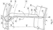
- stator blades 28 variably inclined and also variably curved along the height H according to exemplary embodiments of the invention. Only partial views with a single stator blade 28 are shown, but the other stator blades 28 are analogous to FIGS Figures 4 and 5 are distributed in the circumferential direction and formed identically.
- a radially inner blade section 32 initially has an angle of inclination ⁇ of 0 ° and thus runs upright. This angle of inclination ⁇ is maintained over a height H1 which assumes between 50% and 85% of the total height H of the stator blade 28.
- the radially inner blade section 32 is thus characterized by a constant angle of inclination of 0 °, but could also have a variable negative inclination with an angle of less than 30 °.
- the inner blade section 32 also extends straight and uncurved radially outward.
- the inner blade section 32 is adjoined by a radially outer blade section 34 which extends in the direction of the outer housing 18.
- This outer blade section 34 has a lower height H2, which takes up the remaining portion (for example between 14% and 49%) of the total height H, minus the height H3 of a radially outermost section 35 of the stator blade 28, explained below.
- the outer blade section 34 occupy between 49% and 14% of the total height H, especially if the height H3 has a share of 1%.
- the height H3 can take up to 5% (the height H2 is then preferably between 45% and 10% of the total height).
- the sum of the height components H1-H3 always corresponds to the total height H.
- the outer blade section 34 is generally curved and thus more curved than the upright, radially inner blade section 32. Furthermore, the angle of inclination ⁇ of this blade section 34 with respect to the inner blade section 32 increases, preferably by at least 1.3 times, if the inner blade section 32 is at least slightly should be inclined. In any case, however, the blade section 34 has a value different from 0 ° and, for example, a value from 40 ° up to and including 70 °.
- a normal vector V of the outer blade section 34 is also shown. In the present case, this is defined in relation to the pressure side 41 and is orthogonal to this. It faces away from the rotor hub 20 or, in other words, is directed radially outwards, i. H. the pressure side 41 is inclined radially outward. In the present case, this is defined as a positive inclination of the corresponding blade section 34.
- a positive inclination also corresponds to a negative inclination of the suction side 42 in relation to the hub 20 or is associated with such a tendency.
- the radially outer blade section 34 is thus more curved and bent than the radially inner blade section 32.
- a length of the leading edge 30 and thus also an overall surface area of the stator blades 28 are, however, deliberately reduced in order to limit friction losses.
- the radially outermost blade section 35 which adjoins the radially outer spacing 34 with a steep incline and which forms or merges into the transition region 36 to the outer housing 18, in turn has only a slight incline.
- stator blades 28 are off Figure 2 (but also the following Figure 3 ) thus variably curved and variably inclined along its height H.
- FIG. 3 a further embodiment of the invention is shown.
- This also shows the local definition of an angle of inclination ⁇ which is preferred here.
- the angle of inclination ⁇ is used as the (smallest) intersection angle of a reference axis (in this case the front edge 30) and, more precisely, a tangential T determined to the location on this reference axis with a radial axis R.
- the radial axis R runs through a center point M. The latter lies on the longitudinal axis or axis of rotation X.
- the angle of inclination to a radial axis R is determined, with the radial axis R varying depending on the location considered or when changing from is rotated around the axis of rotation X from one place to the next.
- the stator blades 28 are initially inclined counter to the operating direction of rotation B. More precisely, the normal vector V of the pressure side 41 points in the direction of the stator hub 20.
- the angle of inclination ⁇ 1 is determined, for example, by means of a tangential T (entered for an exemplary radially inner point or area), namely as the smallest angle of intersection between these tangentials T and a local or location-specific radial axis R.
- the negative angle of inclination ⁇ 1 is initially essentially maintained over a radial inner section 32 or is only changed by no more than 10% due to slight local curvatures.
- the height H1 of the radially inner section takes between 50% and 85% of the height H.
- a direction of curvature of the stator vane 28 then changes within the inner section 32.
- the stator vane 28 is curved in the operating direction of rotation B and no longer opposite to this, as in the previous area.
- a subsequent radially outer blade section 34 extends over a height portion H2 which can be less than the height portion H1 and / or which is, for example, a maximum of one third of the total height H (preferably between 49% and 14% of H, depending on the following portion H3 ).
- the stator blade 28 has a positive angle of inclination ⁇ 2 , the value of which can be greater than that of the preceding angle of inclination ⁇ 1 (which can be, for example, less than 30 °) and, for example, at least 1.2 times or at least twice that May have value.
- the angle of inclination ⁇ 2 and / or the curvature in the operating direction of rotation B can be up to radially outermost area 35 can be maintained and / or varied by no more than 10%, the inclination angle ⁇ 2 being continuously converted into the inclination angles ⁇ 1 , ⁇ 3 of these adjacent areas 32, 35 during the transition to the outermost area 35 and inner area 32 .
- the angle of inclination ⁇ 2 can be, for example, between 40 ° and 70 ° inclusive.
- the radially outermost region 35 then again comprises a height portion H3 of between, for example, 1% and 5% and is not inclined or inclined by less than 30 °. In any case, it is inclined less than the section 34.
- both the pressure gradient in the radially inner areas can be reduced and the sound reduction in the radially outer areas can be increased due to the strong radially outer inclination.
- a leading edge 30 of the stator blades 28 was used in particular to define the angle of inclination.
- a rear edge, a threading axis or a geometric center line or center plane (for example a longitudinal sectional plane running through a center point) of the stator blades 28 could also be considered.
- the stator blades 28 can also be arranged as such obliquely between the outer housing 18 and the hub 20 (if necessary also without twisting about their own longitudinal axis). Referring to the Figures 2 to 5 the stator blades 28 can thus stand obliquely on the plane of the sheet or extend obliquely into it. An upper edge of the stator blades 28 that faces the outer casing can then enclose an angle with the axis of rotation X or run obliquely to it.
- a height H of the stator blades 28 can generally be equated with a height of the bypass duct 24, but the stator blades 28 can run inclined to the height axis.
- the height of the stator blades 28 can be defined by the distance between the radially inner and outer transition regions 33, 36 or correspond to this distance. Due to the inclination, a length of the stator blades 28, which corresponds to a length of the leading edge 30 or runs along the leading edge and is measured, can, however, be greater than the height H.
Landscapes
- Engineering & Computer Science (AREA)
- Mechanical Engineering (AREA)
- General Engineering & Computer Science (AREA)
- Physics & Mathematics (AREA)
- Fluid Mechanics (AREA)
- Structures Of Non-Positive Displacement Pumps (AREA)
Abstract
- einem um eine Rotationsachse (X) rotierbaren Fan (14); und
- einer Mehrzahl von in Umfangsrichtung verteilten Statorschaufeln (28), die stromabwärts von dem Fan (14) angeordnet sind,
wobei sich die Statorschaufeln (28) jeweils von einer radial inneren Statornabe (20) zu einem radial äußeren Außengehäuse (18) erstrecken,
wobei ein Neigungswinkel (α) einer jeweiligen Statorschaufel (28) variabel ist,
wobei die Statorschaufeln (28) in einem Übergangsbereich zum Außengehäuse (18) einen Neigungswinkel (α) mit einem Betrag von weniger als 30° aufweisen und in wenigstens einem radial weiter einwärts liegenden Bereich einen anderen Neigungswinkel (α).
Description
- Die Erfindung betrifft eine Verdichterstufe mit variabel geneigten Statorschaufeln. Insbesondere kann es sich um eine Verdichterstufe eines Nebenstromtriebwerks handeln, insbesondere für Luftfahrzeuge und ferner insbesondere für die zivile Luftfahrt und/oder für Flüge mit Unterschallgeschwindigkeit. Die Erfindung betrifft auch ein Strahltriebwerk mit einer solchen Verdichterstufe.
- Verdichterstufen (auch als Gebläse oder Ventilator bezeichnet) zur Verdichtung und/oder Beschleunigung von Gasen oder Gasgemischen sind aus dem Stand der Technik bekannt. Sie umfassen allgemein einen Rotor (vorliegend als Fan bezeichnet) und einen stehenden Stator (vorliegend umfassend Statorschaufeln und bevorzugt auch ein Außengehäuse und eine Statornabe). Zumeist sind Verdichterstufen von einem ringförmigen Kanal umgeben. Die Statoren überspannen meist die gesamte radiale Höhe des Kanals oder, anders ausgedrückt, verbinden jeweils ein radial inneres Gehäuse (auch als Statornabe bezeichnet) des Stators mit einem radial äußeren Außengehäuse der Verdichterstufe bzw. des Stators.
- Der Rotor umfasst in der Regel Schaufeln (zum Beispiel Fanschaufeln), welche bei einer Rotation ein umgebendes Gas oder Gasgemisch einsaugen und verdichten. Die daraus resultierende Strömung wird dann durch den Stator und insbesondere entlang dessen Statorschaufeln geleitet.
- Mögliche Anwendungsbeispiele von Verdichterstufen sind Triebwerke ziviler und militärischer Luftfahrzeuge. Hierbei handelt es sich um Gasturbinen und genauer gesagt um Strahltriebwerke. Bei Triebwerken ohne Nebenstromkanal folgt der Stator meist direkt dem Rotor und erstreckt sich bevorzugt über die gesamte Kanalhöhe. Die eingesaugte Strömung durchläuft anschließend bekanntermaßen das sogenannte Kerntriebwerk, bestehend aus einem Verdichter, einer Brennkammer, einer Turbine und einem Düsenabschnitt. Bei Triebwerken mit Nebenstromkanal wird die eingesaugte Umgebungsluft stromäbwärts des Fans meist mittels eines ringförmigen sogenannten Splitters in einen radial äußeren Nebenstrom, der durch einen Nebenstromkanal (auch als Bypasskanal bezeichnet) geleitet wird, und in einen radial inneren Kernstrom geteilt, der das Kerntriebwerk durchströmt. Der Nebenstrom wird in der Regel erst im Austrittsbereich des Triebwerkes wieder mit dem Kernstrom zusammengeführt.
- Weitere Anwendungsbeispiele sind Fanstufen die zur Vortriebsgenerierung von Flugzeugen verwendet werden, im Gegensatz zu den konventionellen Gasturbinen aber extern durch einen Verbrennungs- und/oder Elektromotor angetrieben werden. Dem sich drehenden Rotor und dem stehenden Stator folgt in diesem Anwendungsfall direkt eine Düse, aus der die angesaugte Strömung wieder austritt.
- Auch Gebläsestufen, die zur Be- und Entlüftung oder zum Transport von gasförmigen Fluiden genutzt werden, sind mögliche Anwendungsfälle der Erfindung, z.B. bei Lüftern.
- In an sich bekannter Weise wird das gasförmige Fluid über eine Verdichterstufe eingesaugt und durchströmt die Verdichterstufe entlang einer Strömungsachse (z.B. von einem entgegen der Strömungsrichtung betrachtet vorderen Einlassbereich nahe des Fans zu einem rückseitigen Austrittsbereich, der insbesondere stromabwärts des Stators liegt). Hierin getätigte Bezugnahmen auf eine stromabwärts- oder -aufwärtspositionierung können sich auf diese Strömungsachse und insbesondere diese Strömungsrichtung beziehen.
- Der Rotor saugt das Fluid aus stromaufwärts der Verdichterstufe liegend Umgebungsbereichen ein und beschleunigt dieses. Hinter dem Rotor hat die Strömung für gewöhnlich eine Geschwindigkeitskomponente in Umfangsrichtung des Strömungskanals. In geringer Nähe hinter dem Rotor befindet sich typischerweise der Stator mit einer Mehrzahl stehender Schaufeln. Diese sind in der Regel gleichmäßig in Umfangsrichtung verteilt, können aber auch ungleichmäßig verteilt sein. Der Stator hat die Aufgabe den ungewünschten Strömungsdrall so umzulenken, dass ein größerer Anteil der Strömungsgeschwindigkeit in Richtung der Strömungsachse weist und damit zur Wirkungsgraderhöhung der Verdichterstufe beitragen kann. Aufgrund der über die Kanalhöhe variierenden Strömungsgeschwindigkeit in Achs- und Umfangsrichtung weisen die Statorschaufeln für gewöhnlich eine Verdrehung bzw. Torsion entlang ihrer Höhe bzw. Längsachse auf. Des Weiteren können die Statorschaufeln in Strömungsrichtung gepfeilt sein (also sozusagen schräg nach hinten bzw. vorne verlaufen, sh. nachstehender "sweep"-angle).
- Auch Statorschaufeln gemäß der Erfindung können (insbesondere unabhängig von einem Einsatz in einem Nebenstromtriebwerk oder allgemein in einem Triebwerk) gemäß sämtlicher vorstehender Varianten ausgebildet sein, weisen jedoch die nachstehend erläuterten erfindungsgemäßen Besonderheiten auf.
- Es ist bekannt, dass die Interaktion der Strömungsinhomoginitäten, die durch die Umströmung der Rotorschaufeln hervorgerufen werden, mit den Statorschaufeln zu unerwünschten Schallentwicklungen führt. Insbesondere führt die Interaktion der Rotornachläufe mit den Statoren zu einem sogenannten tonalen Interaktionslärm. Neben einem rein radialen Verlauf der Statorschaufeln ist es zum Reduzieren dieses tonalen Interaktionslärms bereits bekannt, die Statorschaufeln gegenüber einer radialen Achse zu neigen. Geeignete Definitionen dieses Winkels werden nachstehend noch erläutert. Der Neigungswinkel ist bisher meist konstant entlang der Länge der Statorschaufeln, welche sich geradlinig geneigt zwischen Statornabe und Außengehäuse erstrecken.
- Ursache der schallmindernden Wirkung einer solchen Neigung ist das Erhöhen des Phasenversatzes zwischen den Rotornachläufen und den Schaufelvorderkanten des Stators. Hierdurch wird die Anzahl an Phasenwechseln der resultierenden Dipolquellen auf der Statorvorderkante erhöht, was tendenziell zu vermehrten destruktiven Interferenzen bei der akustischen Abstrahlung der Dipolquellen von den Statorschaufeln in den Strömungskanal führt und sich anschließend als Schallwellen stromauf und stromab der Statorschaufeln ausbreitet. Infolge dessen reduziert sich auch die abgestrahlte Schallleistung. Beispiele derartiger vorbekannter Lösungen werden nachstehend anhand der beigefügten
Figuren 4 und 5 erläutert. - Zudem wird die Amplitude der Strömungsanregung normal zur Vorderkante der Statorschaufeln durch die Neigung reduziert, was sich ebenfalls schallmindernd auswirkt.
- Allgemein hat sich gezeigt, dass das Neigen der Statorschaufeln zwar schallmindernd ist, nachteiligerweise aber mit einer Verminderung des Wirkungsgrades einhergehen kann. Ursächlich hierfür ist zum Beispiel die gegenüber rein radial ausgerichteten Statorschaufeln vergrößerte Oberfläche und Länge der geneigten Statorschaufeln, was mit größeren Reibungsverlusten einhergehen kann.
- Neben den anhand der nachstehenden
Figuren 4 und 5 diskutierten vorbekannten Lösungen ist ein Ausgangspunkt der vorliegenden Erfindung dieEP 2 075 413 A1 . Dort sind Statorschaufeln mit Neigungswinkel offenbart. DieWO 2016/148692 A1 offenbart Statorschaufeln mit nahe eines Außengehäuses radial weiter einwärts liegenden Bereichen. - Weiterer technologischer Hintergrund findet sich in folgenden Druckschriften:
EP 3 453 835 A1 ,DE 60 2004 000 160 T2 ,EP 2 706 240 A2 ,WO 2012/134937 A1 ,US 2017/0114796 A1 undEP 1 939 399 A2 . - Aufgabe der vorliegenden Erfindung ist es daher, die abgestrahlte Schalleistung einer Verdichterstufe bei begrenzter oder sogar ausbleibender Auswirkung auf den Wirkungsgrad zu verringern. Diese Aufgabe wird durch die Gegenstände gemäß den beigefügten unabhängigen Ansprüchen gelöst. Vorteilhafte Weiterbildungen sind in den abhängigen Ansprüchen angegeben. Ferner versteht es sich, dass die in der einleitenden Beschreibung erwähnten Merkmale und Erläuterungen einzeln oder in beliebiger Kombination auch bei der vorliegend offenbarten Lösung vorgesehen sein bzw. auf diese zutreffen können, sofern nicht anders angegeben oder ersichtlich.
- Erfindungsgemäß wurde erkannt, dass ursächlich für Wirkungsgradverluste zum Beispiel die gegenüber rein radial ausgerichteten Statorschaufeln vergrößerte Oberfläche und Länge der bisherigen geneigten Statorschaufeln ist, was mit größeren Reibungsverlusten einhergehen kann. Durch die Neigung der Statorschaufeln nahe der Statornabe können außerdem Druckgradienten auftreten, die unerwünschte Umlenkungen der Strömung innerhalb der geschilderten Kanäle zur Folge haben und möglicherweise zu einer Minderung des Wirkungsgrades führen. Dieser Effekt ist bekannt und z.B. bei Grieb "Verdichter für Turbo-Flugtriebwerke", Springer Verlag, 2009, ISBN 978-3-540-34374-5 erwähnt. Er wird jedoch bisher nicht ausreichend praktisch berücksichtigt und kompensiert. Weiter ist es auch nicht möglich, aufgrund fertigungstechnischer und/oder fertigungswirtschaftlicher Begrenzungen und/oder der mechanischen Stabilität die Statorschaufeln beliebig stark zu neigen.
- Die Erfindung sieht daher vor, als einen zusätzlichen Freiheitsgrad, mit dem eine Schallminderung erreicht werden kann, aber auch die vorstehenden Nachteile und insbesondere Wirkungsgradminderungen zumindest teilweise begrenzt werden können, den Neigungswinkel variabel zu gestalten. Insbesondere kann dieser entlang einer (radialen) Höhe der Statorschaufeln und/oder Länge von deren Vorderkanten variabel gestaltet werden. Hierdurch wird ermöglicht, die Form und insbesondere Neigung der Statorschaufeln je nach den lokalen bzw. örtlichen Verhältnissen geeignet anzupassen.
- Insbesondere wird hierdurch die Möglichkeit geschaffen, in radial außen liegenden Bereichen (zum Beispiel nahe zu dem Außengehäuse) größere Neigungen als in radial innen liegenden Bereichen (zum Beispiel nahe der Statornabe) vorzusehen.
- Es wurde erkannt, dass sich hierdurch besonders starke schallmindernde Wirkungen einstellen, da in radial äußeren Bereichen typischerweise Strömungsverhältnisse (insbesondere Geschwindigkeitsprofile und Amplituden) vorliegen, die eine Schallentwicklung besonders begünstigen.
- Insbesondere wurde erkannt, dass hierdurch auch die Möglichkeit geschaffen wird, Statorschaufeln nahe der Statornabe nicht oder nur gering zu neigen, sodass vorstehend erläuterte Druckgradienten abgeschwächt werden.
- Insbesondere eine Kombination aus geringer oder keiner Neigung nahe der Statornabe, bevorzugt aber deutlich höherer (z.B. wenigstens 40°) Neigung in radial äußeren Bereichen führt dazu, dass in den für die Schallentwicklung besonders maßgeblichen radial äußeren Bereichen eine erhöhte Schallreduzierung möglich ist. In den für die Schallentwicklung weniger maßgeblichen radial inneren Bereichen kann hingegen die Oberfläche der Statorschaufeln und können folglich auch Reibungsverluste begrenzt werden.
- Als besonders vorteilhaft hat sich aber eine geringe oder auch keine Neigung in radial äußersten Schaufelabschnitten erwiesen, insbesondere wenn hierdurch ein vormals stark geneigter Schaufelabschnitt sozusagen wieder umgelenkt wird.
- Insbesondere wird eine Verdichterstufe, insbesondere für ein Nebenstromtriebwerk für Luftfahrtzeuge, vorgeschlagen, mit:
- einem um eine Rotationsachse rotierbaren Fan; und
- einer Mehrzahl von in Umfangsrichtung verteilten Statorschaufeln (insbesondere in einem Nebenstromkanal eines Nebenstromtriebwerks), die stromabwärts von dem Fan angeordnet sind,
- Insbesondere kann der Neigungswinkel in dem genannten Schaufelabschnitt weniger als 10° oder weniger als 5° betragen. Allgemein können also die Statorschaufeln im Wesentlichen aufrecht in das Außengehäuse übergehen.
- Unter dem Neigungswinkel einer Statorschaufel kann der (bevorzugt kleinste) Winkel zwischen der radialen Achse und wahlweise der Schaufelvorderkante, der Schaufelhinterkante, der sogenannten Fädlungsachse (welche in radialer Richtung verläuft und/oder durch den Flächenschwerpunkt einer Mehrzahl von Schaufelquerschnittsflächen) oder einer anderweitig definierten Achse entlang der Statorschaufel verstanden werden. Bei einem aufrechten Verlauf entlang der radialen Achse würde sich also ein Neigungswinkel von 0° ergeben.
- Die betrachtete Kante oder Achse der Statorschaufel (gegebenenfalls auch die radiale Achse) kann auch in eine Ebene projiziert werden, welche orthogonal zur Rotationsachse verläuft (d. h. der Neigungswinkel kann innerhalb dieser Ebene definiert sein).
- Je nach betrachtetem Abschnitt oder Ort einer Statorschaufel kann bspw. durch ortsabhängige Rotation der radialen Achse um die Längsachse (und/oder Rotationsachse), eine jeweilige diesen Ort oder Abschnitt schneidende (sozusagen lokale) radiale Achse oder kann der Schnittwinkel zwischen einer Tangentialen durch den Ort/Abschnitt und der radialen Achse betrachtet werden.
- Die Statorschaufeln können jeweils zwei Schaufelflächen aufweisen, von denen eine auf einer Druckseite und eine auf einer Saugseite liegt. Diese Schaufelflächen können durch die Vorderkante und/oder Hinterkante miteinander verbunden sein.
- Die Definition einer Druckseite und Saugseite von Statorschaufeln sind dem Fachmann geläufig. Allgemein kann die Druckseite konkav gewölbt sein und/oder kann die Saugseite konvex gewölbt sein.
- Der Neigungswinkel (insbesondere dessen Vorzeichen) kann anhand des Normalenvektors von wenigstens einer der Schaufelflächen definiert sein. Im Folgenden kann insbesondere auf den Normalenvektor der Schaufelfläche auf der Druckseite abgestellt werden.
- Ist der Normalenvektor auf der Druckseite in Richtung der Rotornabe gerichtet (bzw. weist auf diese oder allgemein radial einwärts), liegt bevorzugt eine negative Neigung vor. Ist der Normalenvektor auf der Druckseite von der Rotornabe weggerichtet (bzw. weist von dieser weg oder allgemein radial auswärts), liegt bevorzugt eine positive Neigung vor. Bei einem parallelen Verlauf liegt hingegen keine Neigung beziehungsweise eine Neigung von 0° vor.
- Je nach einem betrachteten Ort der Statorschaufel und insbesondere der Druckseite können also unterschiedliche ortsabhängige Normalenvektoren betrachtet werden. Entlang einer Statorschaufel-Höhe bzw. der radialen Achse können auch positiv und negativ geneigte Statorschaufelabschnitte vorliegen.
- Allgemein kann der Neigungswinkel auch dort als positiv definiert sein, wo die Saugseite (und insbesondere deren Normalenvektor) der Rotornabe zugewandt ist oder in deren Richtung weist. Dann ist die Druckseite (und insbesondere deren Normalenvektor) vorteilhafterweise gegenteilig geneigt und weist von der Rotornabe weg und/oder nach radial außen.
- Alternativ kann der Neigungswinkel dort als negativ definiert sein, wo die Druckseite (und insbesondere deren Normalenvektor) der Rotornabe zugewandt ist oder in deren Richtung weist. Dann ist die Saugseite (und insbesondere deren Normalenvektor) vorteilhafterweise gegenteilig geneigt und weist von der Rotornabe weg und/oder nach radial außen.
- Gemäß einer Variante erstreckt sich die radiale Achse ausgehend von einem geometrischen (Kreis-) Mittelpunkt der Verdichterstufe, des Nebenstromtriebwerks oder von einem Stator der Verdichterstufe. Dieser Mittelpunkt liegt bevorzugt auf der Rotationsachse, einer Längsachse der Verdichterstufe und/oder einer (Haupt-) Strömungsachse. Der Mittelpunkt kann insbesondere in einer orthogonal zur Längsachse und/oder Strömungsachse verlaufenden Querschnittsebene betrachtet einen geometrischen Mittelpunkt des ringförmigen Außengehäuses und/oder der ringförmigen Statornabe bilden oder, anders ausgedrückt, einen Mittelpunkt um den diese Komponenten bevorzugt kreisringförmig verlaufen und ausgebildet sind.
- Allgemein können radiale Achsen in einer geneigten und insbesondere orthogonalen Ebene zur Rotationsachse, Längsachse und/oder Strömungsachse verlaufen und diese Achsen jeweils schneiden bzw. von diesen ausgehen. Eine radiale Richtung kann dabei allgemein von dem Mittelpunkt und/oder der Längsachse und/oder der Strömungsachse nach außen bzw. von diesen weggerichtet sein.
- Insbesondere können Ebenen, welche die radialen Achsen enthalten, von der Rotationsachse, Längsachse und/oder Strömungsachse punktuell durchstoßen werden. Sie können diese Achse aber nicht vollständig enthalten. Es handelt sich also bevorzugt nicht um Längsschnittebenen durch die Verdichterstufe, sondern um Querschnittsebenen hiervon, wobei diese Querschnittsebenen bevorzugt, aber nicht zwingend orthogonal zur Längsachse verlaufen müssen.
- Der Neigungswinkel kann allgemein in einer die radiale Achse enthaltenen Ebene definiert sein. Bevorzugt ist er in einer Ebene definiert, die die Vorderkante, Hinterkante oder Fädelachse einer jeweiligen Statorschaufel enthält. Falls die Statorschaufeln in Strömungsrichtung betrachtet nach hinten geneigt ist (also angeschrägt ist oder, gemäß der Fachsprache, eine "sweep"-Winkel von mehr als 0° aufweist), kann eine die genannten Kanten oder Achse enthaltene Ebene zur Längsachse geneigt und/oder ebenfalls entsprechend angeschrägt sein. Wie erwähnt, können die Kanten oder kann die Achse alternativ in eine Ebene, die zum Beispiel orthogonal zur Längsachse oder Rotationsachse verläuft, hineinprojiziert werden und kann der Neigungswinkel dann zwischen der radialen Achse und dieser projizierten Kanten oder Achse definiert sein.
- Allgemein definiert der "sweep"-Winkel einen Winkel von insbesondere der Vorderkante einer Statorschaufel zur (Triebwerks-) Längsachse oder liegt zumindest in einer die Längsachse enthaltenen Ebene. Es handelt sich somit nicht um einen Winkel zur radialen Achsen, zumindest nicht in quer zur Längsachse verlaufenden Ebenen, wie der vorliegend betrachtete Neigungswinkel (in der Fachsprache auch als "lean"-Winkel bezeichnet).
- Der Begriff Neigungswinkel wird hierin in Bezug auf Statorschaufeln in fachüblicherweise verwendet und wird vom Fachmann auch in der hierin geschilderten Weise verstanden. Insbesondere wird dieser Begriff vom Fachmann, wie im Zusammenhang mit den nachstehenden Figuren geschildert, verwendet und auf diese Figuren entsprechend gelesen.
- Es wird verwiesen auf die entsprechenden Winkelbezeichnungen und -definitionen in "Design Selection and Analysis of a Swept and Leaned Stator Concept"; Envia, E. und Nallasamy, M., Journal of Sound and Vibration 228.4, S. 793-836 (1999), sh. dort insbesondere
Figur 1 . - Bevorzugt wird der Neigungswinkel als lokale oder ortsabhängige Größe definiert. Der lokale Neigungswinkel ergibt sich zwischen der Tangente zur definierten Bezugsachse (z.B. Vorder- oder Hinterkante oder der Fädlungsachse) und einer radialen Achse. Diese radiale Achse kann z.B. derart um die Längsachse rotiert werden, dass sie die Bezugsachse jeweils in dem lokalen Ort schneidet, für den der Neigungswinkel ermittelt werden soll. Anders gesagt wird die radiale Achse derart ausgerichtet, dass sie durch den Mittelpunkt des zumeist rund ausgeführten Stators und dem Ort auf der Bezugsachse des Stators verläuft, für den der lokale Neigungswinkel ermittelt werden soll. Je Ort kann also eine eigens ausgerichtete (lokale) radiale Achse betrachtet werden.
- Zusammengefasst kann der Neigungswinkel in einer Ebene definiert sein (insbesondere in einer aufrechten oder geneigten Querschnittsebene), die von der Rotationsachse, Längsachse und/oder Strömungsachse lediglich punktuell durchstoßen wird und/oder die keinen Längsschnitt durch die Verdichterstufe definiert.
- Die Statorschaufel kann erfindungsgemäß variabel gekrümmt sein und/oder Neigungswinkel mit variablen Beträgen aufweisen. Die genannten Variabilitäten können dabei ortsbezogen verstanden werden können, und zwar bevorzugt bezogen auf Orte entlang einer Vorderkante, Hinterkante oder Fädelachse einer jeweiligen Statorschaufel und/oder Orte entlang einer Höhenachse der Statorschaufel und/oder in radialer Richtung aufeinanderfolgende Orte der Statorschaufel.
- Es können also örtliche variierende Krümmungen und/oder Neigungen vorliegen. Insbesondere im Vergleich zwischen radial äußeren (bevorzugt stark gekrümmten und/oder geneigten) Orten und radial inneren (bevorzugt weniger stark gekrümmten und/oder geneigten) Orten können diese Variationen auftreten, wobei aber im radial äußersten und/oder radial innersten Bereich, also an den Übergängen zu den Kanalwänden, bevorzugt nur eine geringe oder auch gar keine Krümmung vorliegt.
- Es wurde erkannt, dass vor allem letzteres Merkmals eine besonders vorteilhafte Lösung der eingangs gestellten Aufgabe ermöglicht, insbesondere da damit Schallentwicklungen signifikant begrenzt werden können.
- Alternativ formuliert kann also die Statorschaufel entlang ihrer Vorderkante und/oder ihrer Höhe und/oder in radialer Richtung verschiedenartige Winkel, Krümmungen und/oder Abstände der genannten Art aufweisen. Hierdurch ergeben sich die gegenüber dem geschilderten Stand der Technik mit konstantem Neigungswinkel zusätzliche Freiheitsgrade und somit Möglichkeiten zur lokal vorteilhaften Ausbildung der Statorschaufeln hinsichtlich Wirkungsgrad und Schallminderung.
- Eine Weiterbildung sieht vor, dass ein Betrag des Neigungswinkels ausgehend von der Statornabe und hin zu dem Außengehäuse zumindest abschnittsweise zunimmt. Insbesondere kann ab einem Abschnitt (z.B. frühestens ab der Hälfte oder frühestens ab zwei Dritteln der (radialen) Höhe) eine Neigungs-Zunahme gegenüber einem vorigem radial inneren Abschnitt vorliegen. Diese Zunahme, die allgemein aus einer zumindest einmaligen Neigungswinkeländerung resultieren kann, kann über eine gewisse Abschnittslänge aufrechterhalten werden, insbesondere (fast) bis zum Erreichen des Außengehäuses und/oder eines radial äußeren Endes der Statorschaufel. Dann kann wiederum eine geringere oder auch gar keine Neigung vorgesehen sein, sodass der allgemein bevorzugte nahezu oder vollständig aufrechte Übergang in das Außengehäuse erfolgt.
- Es kann also eine Neigungswinkeländerung vorliegen und genauer gesagt eine Neigungswinkelvergrößerung, wobei dieser vergrößerte Neigungswinkel dann bevorzugt über einen gewissen Abschnitt beibehalten oder zumindest um nicht mehr als 25% wieder reduziert wird, zumindest bis der weniger stark oder auch gar nicht geneigte Abschnitt im Übergangsbereich zum Außengehäuse erreicht wird.
- Dies kann allgemein in einem gering geneigten oder auch aufrechten radial inneren Abschnitt (z.B. zumindest einem radiale inneren Drittel, zumindest einer radial inneren Hälfte oder zumindest radial inneren zwei Dritteln) resultieren, der in einen stärker geneigten radial äußeren Abschnitt übergeht (z.B. zumindest einem radiale äußeren Drittel, zumindest einer radial äußeren Hälfte oder zumindest radial äußeren zwei Dritteln), welcher dann wiederum in einen weniger stark geneigten oder auch aufrechten radial äußersten Abschnitt oder auch in den entsprechenden Übergangsbereich übergeht. Alternative Definitionen der relativen Größenverhältnisse und insbesondere Höhenverhältnisse dieser Abstände zueinander finden sich nachstehend.
- Allgemein kann der radial äußerste Abschnitt und/oder Abschnitt im Übergangsbereich bis zu 5 % der (radialen) Höhe oder auch allgemein radialen Erstreckung der Statorschaufeln einnehmen.
- Auf diese Weise kann der für Lärmentwicklung kritische radial äußere Bereich für eine Schallminderung vergleichsweise stark geneigt werden, ohne die Gesamtoberfläche der Statorschaufel und damit einhergehende Reibung entlang der gesamten Höhe zu erhöhen. Der radial innere Bereich kann nämlich weniger stark geneigt sein. Allgemein gilt, dass je stärker die Neigung, desto größer auch eine Länge und somit Oberfläche einer Statorschaufel bzw. eines Abschnitts hiervon. Der wenig geneigte oder auch radial aufrechte Übergang der Statorschaufel zum Außen und bevorzugt auch Innengehäuse (Statornabe) reduziert die durch die Überlagerung der Grenzschicht des Gehäuses und der Schaufelgrenzschicht entstehenden Wirbelsysteme und demzufolge auch die Wirkungsgradverluste.
- Eine Weiterbildung sieht vor, dass ein radialer Abstand zwischen Statornabe und Außengehäuse eine Höhe des Strömungskanals (insbesondere eines Nebenstromkanals) und/oder der Statorschaufeln definiert, wobei die Statorschaufeln jeweils einen radial äußeren Schaufelabschnitt oberhalb der halben Höhe des Strömungskanals aufweisen und einen radial inneren Schaufelabschnitt unterhalb der halben Höhe des Strömungskanals aufweisen; und wobei der Betrag des Neigungswinkels des radial äußeren Schaufelabschnitts zumindest abschnittsweise (zum Beispiel bis zum Erreichen des radial äußersten Abschnitts und/oder Übergangsbereich zum Außengehäuse) größer als der Betrag des Neigungswinkels des radial inneren Schaufelabschnitts ist.
- Auch eine Unterteilung in maximal ein Drittel der Höhe für den radial äußeren und maximal zwei Drittel der Höhe für den radial inneren Schaufelabschnitt ist möglich. Bevorzugt nimmt der radial äußere Schaufelabschnitt zwischen 50% und 85% Gesamthöhe ein.
- Die genannten Schaufelabschnitte können auch lediglich Orte bzw. Punkte sein. Sie müssen also nicht die gesamte radial äußere und innere Hälfte umfassen, was aber bei der inneren Hälfte optional vorgesehen sein kann. Stattdessen kann es sich um lokale Abschnitte handeln, die entsprechend oberhalb der halben Höhe (zum Beispiel bis zum Erreichen des radial äußersten Abschnitts und/oder das Übergangsbereich) oder unterhalb davon liegen und die verschiedenartige Neigungswinkel aufweisen. Erneut ergeben sich Vorteile dahingehend, dass insbesondere im radial äußeren Bereich gezielt auf Schallentwicklungen reagiert werden kann, ohne aber die insgesamt von den Statorschaufeln erzeugten Reibungsverluste stark zu erhöhen.
- Gemäß einer Ausführungsform kann auch vorgesehen sein, dass das Vorzeichen der Neigungswinkel dieser Abschnitte unterschiedlich ist. Insbesondere kann der Neigungswinkel des radial inneren Schaufelabschnitts negativ sein (d. h. entgegen der Betriebsdrehrichtung geneigt sein), wohingegen der des radial äußeren Schaufelabstands positiv sein kann (d. h. in Betriebsdrehrichtung geneigt). Hierdurch kann im radial inneren Bereich der vorstehend geschilderte Druckgradient reduziert werden.
- Weiter können die Statorschaufeln jeweils von radial innen nach radial außen betrachtet einen radial inneren Schaufelabschnitt, einen radial äußeren Schaufelabschnitt und einen radial äußersten Schaufelabschnitt aufweisen, und die Neigungswinkel der unmittelbar aufeinanderfolgenden Schaufelabschnittte können sich jeweils voneinander unterscheiden (also vom inneren zum äußeren und von äußeren zum äußersten).
- In diesem Zusammenhang kann ferner vorgesehen sein, dass die Schaufelabschnitte einen Höhenanteil an der (Gesamt-) Höhe der Statorschaufel einnehmen, und wobei unter der Voraussetzung, dass die Summe der Höhenanteile 100% ergibt, folgendes gilt:
- der Höhenanteil des radial inneren Schaufelabschnitts nimmt zwischen 50% und 85% der Höhe ein;
- der Höhenanteil des radial äußeren Schaufelabschnitts nimmt zwischen 14% und 49% der Höhe ein; und
- der Höhenanteil des radial äußersten Schaufelabschnitts nimmt zwischen 1% und 5% der Höhe ein.
- Es wurde festgestellt, dass hierdurch die Aufgabe besonders gut gelöst wird.
- Es können folgende Neigungswinkelbeträge und/oder Neigungen in den Schaufelabschnitten vorgesehen sein, allein oder in beliebiger Kombination:
- weniger als 30° im radial inneren Schaufelabschnitt und/oder eine positive oder negative Neigung;
- zwischen einschließlich 40° und einschließlich 70° im radial äußeren Schaufelabschnitts und/oder eine positive Neigung;
- eine Neigung von weniger als 20° im radial äußeren Schaufelabschnitt und/oder eine bevorzugt positive Neigung (falls von 0° verschieden).
- Die Neigungswinkel können als Maximalwerte verstanden werden. In den Übergangsbereichen zwischen den verschiedenen Abschnitten der Schaufel und insbesondere auch bei den Übergängen zur Nabe und zum Außengehäuse können die Neigungswinkel kontinuierlich ineinander übergehen. Allgemein können sie innerhalb der genannten Abschnitte einer Variation unterliegen (d.h. nicht über die gesamten Abschnitt konstant sein), die dem Zwecke der Schallreduzierung und Wirkungsgradsteigerung dienen.
- Weiter kann vorgesehen sein, dass der (lokale) Neigungswinkel der Statorschaufeln das Vorzeichen mindestens einmal wechselt. Insbesondere kann die Statorschaufel zunächst in eine erste Richtung (zum Beispiel negative Richtung) gegenüber der radialen Achse geneigt sein und dann ab einer gewissen Höhe (zum Beispiel frühestens ab ca. der Hälfte oder zwei Dritteln der Höhe) in die andere Richtung geneigt sein. Allgemein kann die Statorschaufel von radial innen nach radial außen betrachtet erst entgegen der und dann in die Betriebdrehrichtung gekrümmt sein.
- Allgemein kann vorgesehen sein, dass ein radial innerer Neigungswinkel gegenüber der radialen Achse ausgehend von der Statornabe zunächst über eine gewisse Höhe aufrechterhalten wird und dann die Neigung in Richtung der Achse verändert wird. Anschließend kann sich der Wert des Neigungswinkels wieder vergrößern und insbesondere größere (positive) Beträge annehmen, als dies als dies in radialen inneren Abschnitten der Fall war. Anschließend können sie sich mit einer bevorzugt stärkeren und positiven Neigung weiter zu dem Übergangsbereich zum Außengehäuse erstrecken, an dem die einleitend erwähnte weniger ausgeprägte Neigung vorgesehen sein kann.
- Wie bereits erwähnt, kann der Fan in eine Betriebsdrehrichtung rotierbar sein. Hierbei handelt es sich um eine Drehrichtung, die der Fan im Betrieb der Verdichterstufe zum Erzeugen einer Vorschubkraft oder allgemein einer gewünschten Strömungsrichtung (insbesondere einer Einsaugrichtung) aufweist und für die die Verdichterstufe allgemein konstruktiv ausgelegt ist. Der Fachmann kann eine solche Betriebsdrehrichtung auch bei stehendem Fan und inaktivem Zustand der Verdichterstufe problemlos erkennen, insbesondere an einer Form der Schaufeln des Fans.
- In diesem Zusammenhang kann ferner vorgesehen sein, dass die Statorschaufeln ausgehend von oder nahe der Statornabe (und/oder in radial inneren Bereichen unterhalb einer halben Höhe) jeweils zunächst entgegen der Betriebsdrehrichtung geneigt sind. Dies kann mit negativen Neigungswinkeln der vorstehend erläuterten Art einhergehen und/oder in solchen resultieren.
- Zusätzlich oder alternativ kann vorgesehen sein, dass die Statorschaufeln im Übergangsbereich zum Außengehäuse (und/oder in radial äußeren Bereichen oberhalb einer halben Höhe) jeweils in Richtung der Betriebsdrehrichtung geneigt sind. Dies kann mit positiven Neigungswinkeln der vorstehend erläuterten Art einhergehen und/oder in solchen resultieren. Erfindungsgemäß kann eine solche Neigung aber auch ausbleiben. Gemäß einer Weiterbildung sind die Statorschaufeln jeweils zumindest abschnittsweise im Wesentlichen ungekrümmt, insbesondere nahe der Statornabe und/oder in radial inneren Bereichen unterhalb einer halben Höhe. Anders ausgedrückt können sich die Statorschaufeln zumindest abschnittsweise gerade erstrecken. Hierbei kann es sich insbesondere um radial innere Abschnitte handeln, die dann in einen stärker geneigten radial äußeren Abschnitt übergehen. In einem radial äußersten Abschnitt kann aber bevorzugt wieder weniger stark oder auch gar nicht geneigt werden. Spätestens ab und/oder zumindest in dem Übergangsbereich zum radial äußeren Abschnitt, der bevorzugt auf frühesten halber oder frühestens zwei Drittel der Höhe liegt, kann dann eine Krümmung vorliegen. Auch in einem Übergangsbereich zum radial äußersten Abschnitt kann eine Krümmung, dann bevorzugt in anderer Richtung, vorliegen.
- Ein Abschnitt kann dann als im Wesentlichen ungekrümmt angesehen werden, wenn dieser weniger als 10 % oder weniger als 5% einer maximalen Krümmung (bzw. Krümmungsradius) der Statorschaufel aufweist.
- Das Vorsehen zumindest abschnittsweise ungekrümmter Abschnitte ist fertigungstechnisch günstig und kann insbesondere in Kombination mit einer dennoch möglichen negativen Neigung im radial inneren Bereich eine positive Wirkung auf den aerodynamischen Wirkungsgrad (siehe vorstehend erläuterte Möglichkeit zur Reduzierung eines dortigen Druckgradients).
- Hierin erwähnte Krümmungen können sich insbesondere auf eine Vorderkante, der Hinterkante oder der Fädelachse der Statorschaufeln beziehen und/oder auf Krümmung in derselben Ebene wie der Neigungswinkel. Allgemein ausgedrückt kann es sich um Krümmungen in einer Raumebene handeln, die die genannten Kanten oder die genannte Achse einer jeweiligen Statorschaufel umfasst. Anders ausgedrückt kann es sich um Krümmungen entlang einer Höhenachse einer jeweiligen Statorschaufel handeln. Nicht gemeint sein können Verdrehungen oder Verwindungen der gesamten Statorschaufel um deren Höhenachse (zum Beispiel im Sinne einer Tordierung).
- Allgemein kann vorgesehen sein, dass eine jede Statorschaufel entlang ihrer Höhe variabel gekrümmt ist (d. h. einen variablen Krümmungsradius aufweist). Im Gegensatz zum Stand der Technik können sich die Statorschaufeln oder zumindest deren Vorderkanten (wahlweise auch die Hinterkante oder die Fädelachse) also nicht ausschließlich gerade erstrecken, sondern können zumindest abschnittsweise oder lokal gekrümmt sein. Insbesondere kann vorgesehen sein, dass eine jeweilige Krümmung der Statorschaufeln von radial innen nach radial außen zumindest abschnittsweise zunimmt.
- Eine Änderung des Krümmungsradius kann insbesondere unmittelbar vor einem radial äußersten Abschnitt und/oder Übergangsbereich zum Außengehäuse vorliegen, insbesondere in der Form, dass der entsprechende Übergangsbereich der Statorschaufeln bzw. deren radial äußerster Abschnitt dann einen anderen und allgemein weniger starken Neigungswinkel aufweist.
- Die Erfindung betrifft auch ein Strahltriebwerk, umfassend eine Verdichterstufe nach einem der vorangehenden Ansprüche.
- Im Folgenden werden Ausführungsformen der Erfindung anhand der beigefügten schematischen Figuren erläutert. In Ihrer Art und/oder Funktion übereinstimmende Merkmale können dabei figurenübergreifend mit den gleichen Bezugszeichen versehen sein.
- Fig. 1
- zeigt einen Teilausschnitt eines Nebenstromtriebwerks mit einer Verdichterstufe gemäß einer ersten Ausführungsform;
- Fig. 2
- zeigt eine Teilansicht eines Stators des Nebenstromtriebwerks aus
Figur 1 ; - Fig. 3
- zeigt eine Teilansicht eines Stators gemäß einer zweiten Ausführungsform;
- Fig. 4-5
- zeigen Frontansichten von Statoren gemäß dem Stand der Technik.
- In
Figur 1 ist ein Teilausschnitt eines Strahltriebwerks in Form eines Nebenstromtriebwerks 1 gezeigt, wie es aus dem Stand der Technik allgemein bekannt ist. Allerdings sind die nachfolgend erläuterten Statorschaufeln 28 gemäß einer Ausführungsform der Erfindung ausgebildet. Das Nebenstromtriebwerk 1 umfasst eine Verdichterstufe 10 mit dem nachfolgend erläuterten Fan 14 und dem Stator 21 samt dazugehöriger Komponenten (insbesondere der Statorschaufeln 28). - Es handelt sich bei der gezeigten Ansicht um eine Teilschnittansicht, die eine Längsachse enthält, welche auch eine Hauptströmungsachse definiert, entlang derer Luft durch das Triebwerk strömt. Zudem definiert die Längsachse auch eine Rotationsachse X bzw. entspricht dieser, um die der nachfolgend erläuterte Rotor, der hierin als Fan 14 bezeichnet wird, der Verdichterstufe 10 rotiert.
- Die Strömungsrichtung S der Luft durch das Nebenstromtriebwerk 1 ist ebenfalls angedeutet und verläuft allgemein von links nach rechts. Die Luft wird in an sich bekannter Weise an einem in
Figur 1 links positionierten Eintrittsbereich 12 durch Rotation des Fans 14 eingesaugt. - Der Fan 14 umfasst mehrere in Umfangsrichtung um die Längsachse verteilte Fanschaufeln 16, von denen lediglich eine erkennbar ist. Die Fanschaufeln 16 erstrecken sich bis nahezu zur Innenwand eines Außengehäuses 18.
- Der Fan 14 ist in an sich bekannter Weise mit weiteren Triebwerksstufen verbunden, wie zum Beispiel einer Brennkammer und einer Turbine, die in
Figur 1 aber nicht gesondert dargestellt sind. Diese Bestandteile eines Nebenstromtriebwerks 1 sind dem Fachmann geläufig und werden daher nicht näher erläutert. - Wenn die Verdichterstufe 10 nicht in einem Triebwerk 1, sondern z.B. in einem Lüfter zum Einsatz kommt, können auch keine Verdichterstufe 10 nachgelagerten Komponenten vorhanden sein oder lediglich Komponenten, die per erzeugten Luftstrom gekühlt werden sollen.
- Das Außengehäuse 18 kann prinzipiell auch dem Stator 21 zugeordnet werden, da es feststehend ist.
- Die Statornabe 20 weist eine ringförmig um die Längsachse L verlaufende Vorderlippe 22 auf (auch Splitter genannt), welche die Luftströmung in einen radial äußeren und einen radial inneren Anteil aufteilt.
- Der radial äußere Anteil strömt durch einen Nebenstromkanal 24, der zwischen einer Außenseite der Statornabe 20 und einer Innenseite des Außengehäuses 18 verläuft bzw. hiervon eingeschlossen wird. Der Nebenstromkanal 24 ist bevorzugt ein ringförmiger Hohlraum.
- Der radial innere Strömungsanteil, der auch als Kernströmung bezeichnet werden kann, strömt hingegen durch einen sich radial einwärts erstreckenden Kanal 26 zu einem sogenannten Kerntriebwerk (nicht gezeigt), welches die vorstehend erwähnten weiteren Komponenten des Nebenstromtriebwerks 1 umfassen kann.
- Innerhalb des Nebenstromkanals 24 und in dem gezeigten Beispiel nahe der Vorderlippe 22 befindet sich eine Mehrzahl von Umfangsrichtung verteilter Statorschaufeln 28, von denen in
Figur 1 lediglich eine erkennbar ist. Die Statorschaufeln 28 weisen eine dem Fan 14 bzw. Eintrittsbereich 12 zugewandte Vorderkante 30 auf und eine gegenüberliegende Hinterkante 43. Sie erstrecken sich zwischen einem radial inneren Übergangsbereich 33 zum Stator 20, der auch einen radialen inneren Fußpunkt 31 oder auch eine Wurzel der Statorschaufel 28 umfasst, zu einem radial äußeren Übergangsbereich 36 zum Außengehäuse 18. Dieser radial äußere Übergangsbereich 36 kann einen radial äußersten Abschnitt der Statorschaufeln 28 bilden oder umfassen. - Eine Höhe H der Statorschaufeln 28 ist in
Figur 1 ebenfalls markiert. Die Höhenachse H erstreckt sich allgemein in radialer Richtung und fällt mit einer Höhe des Nebenstromkanals 24 im Bereich der Statorschaufel 28 zusammen. - Strichliert angedeutet ist auch eine mögliche Anschrägung der Statorschaufel 28 gemäß einem vorstehend erwähnten "sweep"-Winkel, der hierin aber nicht näher betrachtet wird. Dieser Winkel kann befindet sich in einer die Längsachse L enthaltenen Ebene (also in einem Längsschnitt). Der hierin betrachtete Neigungswinkel α verläuft hingegen in einer orthogonal zur Längsachse L verlaufenden (Querschnitts-) Ebene und wird dort mit einer radialen Achse R eingeschlossen, wie sie nachstehend noch näher erläutert wird.
- Zunächst Bezug nehmend auf die
Figuren 4 und 5 werden im Folgenden Lösungen gemäß dem Stand der Technik erläutert. Die Figuren zeigen Frontansichten eines Stators 21, wie er in einem vergleichbaren Nebenstromtriebwerk 10 zum Einsatz kommen kann. Die Blickrichtung entspricht dem Pfeil S ausFigur 1 . - Gezeigt ist also eine Querschnittsebene durch ein Nebenstromtriebwerk 10, welche orthogonal auf der Längsachse L und Rotationsachse X steht bzw. punktuell von diesen durchstoßen wird. Folglich blickt man auf die Vorderkanten 30 der Statorschaufeln 28.
- Man erkennt zunächst die bereits erwähnte kreisringförmige Ausbildung des Außengehäuses 18 und der Statornabe 20. Diese erstrecken sich um einen Kreismittelpunkt M. Hiervon ausgehend ist auch eine radiale Achse R gezeigt, die in der erwähnten Querschnittsebene liegt.
- Die Statorschaufeln 28 sind mit gleichmäßigen Winkelabständen zueinander in Umfangsrichtung verteilt, was aber nicht zwingend ist. Sie verbinden jeweils das Außengehäuse 18 und den Stator 20 miteinander. Aus Übersichtsgründen sind nur ausgewählte Statorschaufeln 28 samt Vorderkanten 30 mit einem entsprechenden Bezugszeichen versehen.
- In den gezeigten Beispielen, welche das fachüblichen Verständnis eines Neigungswinkels α von Statorschaufeln 28 in der Triebwerkstechnik widerspiegeln, wird der Neigungswinkel α jeweils relativ zu einer radialen Achse R definiert, welche ausgehend von dem Kreismittelpunkt M durch einen Fußpunkt 31 bzw. den erwähnten radial inneren Übergangsbereich 33 einer jeden Statorschaufel 28 verläuft. Je Statorschaufel 28 wird also eine eigene radiale Achse R definiert.
- Eingeschlossen wird der Neigungswinkel α zwischen und ausgehend von dieser radialen Achse R und der Vorderkante 30. Im Fall einer etwaigen Anschrägung der Statorschaufeln 28, wie in
Figur 1 angedeutet und dort erläutert, kann die Vorderkante 30 in die hier betrachtete Querschnittsebene projiziert werden und dann den entsprechenden Neigungswinkel α mit der radialen Achse R einschließen. Auch hierin geschilderte Krümmungen von Statorschaufeln 28 und insbesondere von deren Vorderkanten 30 können in der vorstehend erläuterten Querschnittsebene betrachtet und gegebenenfalls dort hineinprojiziert werden. - Gezeigt ist ferner eine Betriebsdrehrichtung B des Nebenstromtriebwerks 10 bzw. des vorstehend erläuterten Rotors. In den gezeigten Beispielen ist das Nebenstromtriebwerk 10 rechts drehen. Der Neigungswinkel α wird ausgehend von der radialen Achse R hin zu einer jeweiligen Statorschaufel 28 bzw. Vorderkante 30 definiert.
- Verläuft der Neigungswinkel αdabei in die Betriebsrichtung B, wie in
Figur 5 , kann er einen positiven Wert annehmen. Die Statorschaufel 28 ist dann in die Betriebsdrehrichtung B geneigt. Im entgegengesetzten Fall, der nachstehend anhand derFiguren 2 und3 noch erläutert wird, liegt ein negativer Neigungswinkel α und eine Neigung entgegen der Betriebsdrehrichtung B vor. Bevorzugt wird hierin aber eine Vorzeichendefinition des Neigungswinkels α anhand von Normalenvektoren V, was anhand derFiguren 2 und3 nachstehend noch erläutert wird. - Sämtliche vorstehenden allgemeinen Ausführungen treffen auch auf die erfindungsgemäßen Ausführungsformen der
Figuren 2 und3 zu. - In
Figur 4 ist der Fall nicht geneigter Statorschaufeln 28 gezeigt, bei denen der Neigungswinkel α einen Wert von 0° annimmt. - Im Fall von
Figur 5 sind die Statorschaufeln 28 allgemein gleichartig geneigt und zwar mit einem positiven Neigungswinkel α. Für jeden Ort der Statorschaufel 28 entlang der Vorderkante 30 ist dieser Neigungswinkel α gleich. Anders ausgedrückt liegt also eine konstante Neigung oder, anders ausgedrückt, liegt ein konstanter Neigungswinkel α vor, insbesondere bezogen auf bzw. entlang einer Höhe H einer jeweiligen Statorschaufel 28 . Die Statorschaufeln 28 und genauer gesagt deren Vorderkanten 30 (oder die gewählte Bezugsachse, die z.B. die Hinterkante 43 oder Fädelachse sein können) verlaufen allgemein gradlinig und ungekrümmt. - In den
Figuren 2 und3 sind erfindungsgemäße Varianten mit entlang der Höhe H variabel geneigten und auch variabel gekrümmten Statorschaufeln 28 gemäß Ausführungsbeispielen der Erfindung gezeigt. Dabei sind jeweils lediglich Teilansichten mit einer einzelnen Statorschaufel 28 gezeigt, wobei jedoch die weiteren Statorschaufeln 28 analog zu denFiguren 4 und 5 in Umfangsrichtung verteilt und gleichartig ausgebildet sind. - Zunächst Bezug nehmend auf
Figur 2 erkennt man eine konkav gewölbte Druckseite 41 und eine konvex gewölbte Saugseite 42, wobei die Druckseite 41 bezugnehmend auf die Betriebsdrehrichtung B der Saugseite 42 nacheilt. - Ein radial innerer Schaufelabschnitt 32 weist zunächst einen Neigungswinkel α von 0° auf und verläuft somit aufrecht. Dieser Neigungswinkel α wird über eine Höhe H1 aufrechterhalten, welche zwischen 50 % und 85 % der gesamten Höhe H der Statorschaufel 28 einnimmt. Der radial innere Schaufelabschnitt 32 zeichnet sich also durch einen konstanten Neigungswinkel von 0° aus, könnte aber auch eine variable negative Neigung mit einem Winkel von weniger als 30° aufweisen. Der innere Schaufelabschnitt 32 verläuft ferner gerade und ungekrümmt radial nach außen.
- An den inneren Schaufelabschnitt 32 schließt sich ein radial äußerer Schaufelabschnitt 34 an, der sich in Richtung des Außengehäuses 18 erstreckt. Dieser äußere Schaufelabschnitt 34 weist eine geringere Höhe H2 auf, welche den verbleibenden Anteil (zum Beispiel zwischen 14% und 49%) der Gesamthöhe H einnimmt, abzüglich der nachfolgend erläuterten Höhe H3 eines radial äußersten Abschnitts 35 der Statorschaufel 28. Beispielsweise kann der äußere Schaufelabschnitt 34 zwischen 49% und 14% der Gesamthöhe H einnehmen, insbesondere wenn die Höhe H3 einen Anteil von 1 % einnimmt. Allgemein kann die Höhe H3 aber bis zu 5 % einnehmen (die Höhe H2 beträgt dann vorzugsweise zwischen 45 % und 10% der Gesamthöhe). Die Summe der Höhenanteile H1-H3 entspricht stets der Gesamthöhe H.
- Der äußere Schaufelabschnitt 34 verläuft allgemein gekrümmt und somit stärker gekrümmt als der aufrechte radial innere Schaufelabschnitt 32. Ferner nimmt Neigungswinkel α dieses Schaufelabschnitts 34 gegenüber dem inneren Schaufelabschnitt 32 zu, bevorzugt um das wenigstens 1,3-fache, falls der innere Schaufelabschnitt 32 zumindest geringfügig geneigt sein sollte. In jedem Fall weist der Schaufelabschnitt 34 aber einen von 0° verschiedenen Wert und zum Beispiel einen Wert von einschließlich 40° bis zu einschließlich 70° auf.
- Gezeigt ist ferner ein Normalenvektor V des äußeren Schaufelabschnitts 34. Dieser ist vorliegend in Bezug auf die Druckseite 41 definiert und steht orthogonal auf dieser. Er weist von der Rotornarbe 20 weg oder, mit anderen Worten, ist nach radial außen gerichtet, d. h. die Druckseite 41 ist nach radial außen geneigt. Dies wird vorliegend als eine positive Neigung des entsprechenden Schaufelabschnitts 34 definiert.
- Angedeutet ist auch ein Normalenvektor V* auf der Saugseite 42 im selben Bereich des äußeren Schaufelabschnitts 34. Dieser weist radial nach innen bzw. ist auf die Nabe 20 gerichtet. Insofern entspricht eine positive Neigung auch einer negativen Neigung der Saugseite 42 zur Nabe 20 bzw. geht mit einer solchen einher.
- Der radial äußere Schaufelabschnitt 34 ist somit stärker gekrümmt und gebogen, als der radial innere Schaufelabschnitt 32. Es liegt also radial äußere bewusst starke Krümmung und Biegung vor, bevorzugt in die Betriebsdrehrichtung B. Hierdurch werden die vorstehend erwähnten Vorteile einer stärkeren Schallminderung in radial äußeren Bereichen erzielt. Durch eine vergleichsweise geringe Neigung in radial inneren Bereichen wird eine Länge der Vorderkante 30 und somit auch eine Gesamtoberfläche der Statorschaufeln 28 hingegen zum Begrenzen von Reibungsverlusten bewusst reduziert.
- Der radial äußerste Schaufelabschnitt 35, der sich an den radial äußeren Abstand 34 mit starker Neigung anschließt und der den Übergangsbereich 36 zum Außengehäuse 18 bildet bzw. in diesen übergeht, weist hingegen wiederum nur eine geringe Neigung auf. Ein dortiger Neigungswinkel α3 kann allgemein zwischen 0° und maximal 30° betragen. Dieser Neigungswinkel α kann als (vorzugsweise kleinster) Schnittwinkel zwischen einer Tangentialen T entlang der Vorderkante 30 in diesem Schaufelabschnitt 35 und der radialen Achse R definiert sein.
- Allgemein sind die Statorschaufeln 28 aus
Figur 2 (aber auch der nachstehendenFigur 3 ) somit entlang ihrer Höhe H variabel gekrümmt und variabel geneigt. - Es ist prinzipiell und insbesondere bei der Variante aus
Figur 2 auch möglich, in radial inneren Bereichen und insbesondere unmittelbar ausgehend vom Fußpunkt 31 zunächst einen negativen Neigungswinkel α vorzusehen. Dies hilft beim Abbau des vorstehend erläuterten Druckgradients. Dieser Neigungswinkel α kann dann zunehmen und in eine positive Neigung übergehen, wie dies nachstehend anhand vonFigur 3 erläutert wird. Der Vorzeichenwechsel der Neigung liegt insbesondere bei der Variante ausFigur 2 bevorzugt in einer oberen Hälfte der Höhe H. - In
Figur 3 ist eine weitere erfindungsgemäße Ausführungsform gezeigt. Aus dieser wird auch die hierin bevorzugte lokale Definition eines Neigungswinkels α ersichtlich. Für jeden betrachteten Ort wird der Neigungswinkel α als (kleinster) Schnittwinkel einer Bezugsachse (vorliegend der Vorderkante 30) und genauer gesagt einer Tangentialen T an den Ort auf dieser Bezugsachse mit einer radialen Achse R bestimmt. Die radiale Achse R verläuft durch einen Mittelpunkt M. Letzterer liegt auf der Längsachse bzw. Rotationsachse X. Anders ausgedrückt wird also der Neigungswinkel zu einer radialen Achse R bestimmt, wobei die radiale Achse R je nach dem betrachteten Ort variiert bzw. bei einem Wechsel von einem Ort zum nächsten um die Rotationsachse X verdreht wird. - Die Statorschaufeln 28 sind ausgehend von ihrem radial inneren Fußpunkt 31 dabei zunächst entgegen der Betriebsdrehrichtung B geneigt. Genauer gesagt weist der Normalenvektor V der Druckseite 41 in Richtung der Statornabe 20. Wie erwähnt, wird der Neigungswinkel α1 wird beispielhaft mittels einer Tangentialen T ermittelt (eingetragen für einen beispielhaften radial inneren Punkt bzw. Bereich), und zwar als kleinster Schnittwinkel zwischen dieser Tangentialen T und einer lokalen bzw. ortsspezifische radialen Achse R. Der negative Neigungswinkel α1 wird über einen radiale inneren Abschnitt 32 zunächst im Wesentlichen aufrechterhalten bzw. nur durch geringe lokale Krümmungen um nicht mehr als 10 % verändert. Die Höhe H1 des radial inneren Abschnitts nimmt dabei zwischen 50% und 85 % der Höhe H ein.
- Anschließend ändert sich eine Krümmungsrichtung der Statorschaufel 28 (bzw. von dessen Vorderkante 30) innerhalb des inneren Abschnitts 32. Die Statorschaufel 28 ist in Betriebsdrehrichtung B gekrümmt und nicht mehr entgegen hierzu, wie im vorangehenden Bereich. Der Betrag des dortigen Neigungswinkels α2 kann größer als derjenige des vorangehenden radial weitere inneren ersten Neigungswinkels α1 sein. Er kann auch positiv sein, da der Normalenvektor V zunehmend von der Statornabe weggerichtet verläuft. Im Übergangsbereich zwischen dem Neigungswinkel α1 und α2 bei der Höhe H1 weist die Schaufel lokal keine Neigung auf.
- Ein anschließender radial äußerer Schaufelabschnitt 34 erstreckt sich über einen Höhenanteil H2, der geringer als der Höhenanteil H1 sein kann und/oder der zum Beispiel maximal ein Drittel der Gesamthöhe H beträgt (bevorzugt zwischen 49% und 14% von H, je nach nachstehendem Anteil H3). Dort weist die Statorschaufel 28 einen positiven Neigungswinkel α2 auf, dessen Wert größer als derjenige des vorangehenden Neigungswinkels α1 sein kann (der z.B. weniger als 30° betragen kann) und zum Beispiel wenigstens das 1,2-fache oder wenigstens das doppelte von deren Wert aufweisen kann. Der Neigungswinkel α2 und/oder die Krümmung in Betriebsdrehrichtung B kann bis zum radial äußersten Bereich 35 aufrechterhalten und/oder um nicht mehr als 10% variiert werden, wobei beim Übergang zu dem äußersten Bereich 35 und inneren Bereich 32 der Neigungswinkel α2 kontinuierlich in die Neigungswinkel α1,α3 dieser benachbarten Bereiche 32, 35 überführt wird. Der Neigungswinkel α2 kann z.B. zwischen einschließlich 40° bis einschließlich 70° betragen.
- Der radial äußerste Bereich 35 umfasst dann wieder einen Höhenanteil H3 von zwischen z.B. 1 % und 5% und ist nicht geneigt oder um weniger als 30 ° geneigt. In jedem Fall ist er geringer als der Abschnitt 34 geneigt.
- Mittels dieser Variante kann sowohl der Druckgradient im radial inneren Bereichen gemindert, als auch durch die starke radial äußere Neigung die Schallminderung in radial äußeren Bereichen erhöht werden.
- Mit sämtlichen hierin geschilderten beispielhaften Größenverhältnissen und insbesondere Höhenverhältnissen sowie Krümmungs- und Neigungsänderungen wurden geeignete Kompromisse zwischen einer Erhöhung von Reibungsverlusten aufgrund einer vergrößerten Oberfläche und einer Schallminderung erzielt. Beispielsweise haben Simulationen ergeben, dass Schallreduzierungen um mehrere Dezibel mit den gezeigten Lösungen ohne Beeinträchtigung des Wirkungsgrades möglich sind oder aber den Wirkungsgrad um nicht deutlich mehr als ein Prozent verschlechtern (und dann gegebenenfalls auch nur bezogen auf bestimmte Flugphasen).
- Je nach Anwendungsfall kann auch in Kauf genommen werden, dass die Reibungsverluste zu einer gewissen Verringerung des erzielbaren Wirkungsgrades führen, sofern dies mit signifikanten Schallreduzierungen einhergeht. Beispielsweise kann es für Flugzeugbetreiber durchaus relevant sein, lärmabhängige Landegebühren zu reduzieren und dafür während eines Flugs auch einen etwas geringeren Wirkungsgrad in Kauf zu nehmen.
- Im Rahmen dieser Offenbarung wurde zur Definition des Neigungswinkels insbesondere auf eine Vorderkante 30 der Statorschaufeln 28 abgestellt. Alternativ könnte aber ebenso eine Hinterkante, eine Fädelachse oder eine geometrische Mittellinie oder Mittenebene (zum Beispiel eine durch einen Mittelpunkt verlaufende Längsschnittebene) der Statorschaufeln 28 betrachtet werden.
- Die Statorschaufeln 28 können auch (gegebenenfalls auch ohne Verwindung um ihre eigene Längsachse) als solche schräg zwischen dem Außengehäuse 18 und der Nabe 20 angeordnet sein. Bezugnehmend auf die
Figuren 2 bis 5 können die Statorschaufeln 28 also schräg auf der Blattebene stehen bzw. sich schräg in diese hinein erstrecken. Eine Oberkante der Statorschaufeln 28, die dem Außengehäuse zugewandt ist, kann dann einen Winkel mit der Rotationsachse X einschließen bzw. schräg zu dieser verlaufen. - Eine Höhe H der Statorschaufeln 28 kann allgemein mit einer Höhe des Nebenstromkanals 24 gleichgesetzt werden, wobei die Statorschaufeln 28 aber geneigt zur Höhenachse verlaufen können. Die Höhe kann der Statorschaufeln 28 kann durch den Abstand der radial inneren und äußeren Übergangsbereiche 33, 36 definiert sein bzw. diesem Abstand entsprechen. Aufgrund der Neigung kann eine Länge der Statorschaufeln 28, welche einer Länge der Vorderkante 30 entspricht bzw. entlang der Vorderkante verläuft und gemessen wird, jedoch größer als die Höhe H ausfallen.
Claims (10)
- Verdichterstufe (10), insbesondere für ein Nebenstromtriebwerk für Luftfahrtzeuge, mit:- einem um eine Rotationsachse (X) rotierbaren Fan (14); und- einer Mehrzahl von in Umfangsrichtung verteilten Statorschaufeln (28), die stromabwärts von dem Fan (14) angeordnet sind,wobei sich die Statorschaufeln (28) jeweils von einer radial inneren Statornabe (20) zu einem radial äußeren Außengehäuse (18) erstrecken,
wobei ein Neigungswinkel (a) einer jeweiligen Statorschaufel (28) variabel ist,
wobei die Statorschaufeln (28) jeweils in einem an das Außengehäuse (18) angrenzenden Schaufelabschnitt (35) einen Neigungswinkel (a) mit einem Betrag von weniger als 30° aufweisen und in wenigstens einem radial weiter einwärts liegenden Bereich einen Neigungswinkel (a) mit einem hiervon abweichenden Betrag. - Verdichterstufe (10) nach Anspruch 1,
wobei ein Betrag des Neigungswinkels (a) ausgehend von der Statornabe (20) und hin zu dem Außengehäuse (18) zumindest abschnittsweise zunimmt. - Verdichterstufe (10) nach Anspruch 1 oder 2,
wobei ein radialer Abstand zwischen Statornabe (20) und Außengehäuse (18) eine Höhe (H) eines Strömungskanals (24) definieren,
wobei die Statorschaufeln (28) jeweils einen radial äußeren Schaufelabschnitt (34) oberhalb der halben Höhe (H) des Strömungskanals (24) aufweisen und einen radial inneren Schaufelabschnitt (32) unterhalb der halben Höhe (H) des Strömungskanals (24) aufweisen; und
wobei der Betrag des Neigungswinkels (a) des radial äußeren Schaufelabschnitts (34) zumindest abschnittsweise größer als der Betrag des Neigungswinkels (a) des radial inneren Schaufelabschnitts (32) ist. - Verdichterstufe (10) nach einem der vorangehenden Ansprüche,
wobei die Statorschaufeln (28) jeweils von radial innen nach radial außen betrachtet einen radial inneren Schaufelabschnitt (32), einen radial äußeren Schaufelabschnitt (34) und einen radial äußersten Schaufelabschnitt (35) aufweisen, und wobei die Neigungswinkel der unmittelbar aufeinanderfolgenden Schaufelabschnittte (32, 34, 35) sich jeweils voneinander unterscheiden. - Verdichterstufe (10) nach Anspruch 4,
wobei die Schaufelabschnittte (32, 34, 35) jeweils einen Höhenanteil (H1, H2, H3) an der Höhe (H) der Statorschaufel (28) einnehmen, und wobei unter der Voraussetzung, dass die Summe der Höhenanteile (H1, H2, H3) 100% ergibt, folgendes gilt:- der Höhenanteil (H1) des radial inneren Schaufelabschnitts (32) nimmt zwischen 50% und 85% der Höhe (H) ein;- der Höhenanteil (H2) des radial äußeren Schaufelabschnitts (34) nimmt zwischen 14% und 49% der Höhe (H) ein; und- der Höhenanteil (H2) des radial äußersten Schaufelabschnitts (35) nimmt zwischen 1% und 5% der Höhe (H) ein. - Verdichterstufe (10) nach einem der vorangehenden Ansprüche,
wobei ein Vorzeichen des Neigungswinkels (a) entlang der Höhe (H) einer jeden Statorschaufel (28) wenigstens einmal wechselt. - Verdichterstufe (10) nach einem der vorangehenden Ansprüche,
wobei der Fan (14) in eine Betriebsdrehrichtung (B) rotierbar ist und wobei die Statorschaufeln (28) ausgehend von der Statornabe (20) jeweils zunächst entgegen der Betriebsdrehrichtung (B) gekrümmt und/oder geneigt sind. - Verdichterstufe (10) Anspruch 7,
wobei die Statorschaufeln (28) im Übergangsbereich (33) zum Außengehäuse (18) jeweils in Richtung der Betriebsdrehrichtung (B) gekrümmt und/oder geneigt sind. - Verdichterstufe (10) nach einem der vorangehenden Ansprüche,
wobei die Statorschaufeln (28) zumindest abschnittsweise im Wesentlichen ungekrümmt sind, insbesondere nahe der Statornabe (20) und/oder nahe des Außengehäuses (18). - Strahltriebwerk (1), umfassend eine Verdichterstufe (10) nach einem der vorangehenden Ansprüche.
Applications Claiming Priority (1)
| Application Number | Priority Date | Filing Date | Title |
|---|---|---|---|
| DE102019213932.9A DE102019213932B4 (de) | 2019-09-12 | 2019-09-12 | Verdichterstufe mit variabler Statorschaufelneigung |
Publications (2)
| Publication Number | Publication Date |
|---|---|
| EP3792451A1 true EP3792451A1 (de) | 2021-03-17 |
| EP3792451B1 EP3792451B1 (de) | 2024-06-19 |
Family
ID=72432777
Family Applications (1)
| Application Number | Title | Priority Date | Filing Date |
|---|---|---|---|
| EP20195154.8A Active EP3792451B1 (de) | 2019-09-12 | 2020-09-08 | Verdichterstufe mit variabler statorschaufelneigung |
Country Status (2)
| Country | Link |
|---|---|
| EP (1) | EP3792451B1 (de) |
| DE (1) | DE102019213932B4 (de) |
Citations (13)
| Publication number | Priority date | Publication date | Assignee | Title |
|---|---|---|---|---|
| US6554564B1 (en) * | 2001-11-14 | 2003-04-29 | United Technologies Corporation | Reduced noise fan exit guide vane configuration for turbofan engines |
| EP1333181A1 (de) * | 2001-05-24 | 2003-08-06 | Ishikawajima-Harima Heavy Industries Co., Ltd. | Leitschaufel für einen Ventilator mit geringer Geräuschentwicklung |
| US20050008494A1 (en) * | 2003-03-28 | 2005-01-13 | Ishikawajima-Harima Heavy Industries Co., Ltd. | Aircraft engine, fan thereof and fan stator vane thereof |
| US20060210395A1 (en) * | 2004-09-28 | 2006-09-21 | Honeywell International, Inc. | Nonlinearly stacked low noise turbofan stator |
| DE602004000160T2 (de) | 2003-06-30 | 2006-11-30 | Snecma | Leitschaufelstufe eines Verdichters für einen Luftfahrzeugsmotor |
| EP1939399A2 (de) | 2006-12-22 | 2008-07-02 | General Electric Company | Turbinenbaugruppe |
| EP2075413A1 (de) | 2007-12-26 | 2009-07-01 | Techspace aero | Vorrichtung zur Versteifung eines Stators einer Strömungsmaschine und deren Anwendung in Luftfahrzeugmotoren |
| WO2012134937A1 (en) | 2011-03-25 | 2012-10-04 | General Electric Company | High camber stator vane |
| EP2706240A2 (de) | 2012-09-06 | 2014-03-12 | Rolls-Royce plc | Leitschaufelanordnung |
| WO2016148692A1 (en) | 2015-03-17 | 2016-09-22 | Siemens Aktiengesellschaft | Stator vane dampening system usable within a turbine engine |
| US20170114796A1 (en) | 2015-10-26 | 2017-04-27 | General Electric Company | Compressor incorporating splitters |
| EP3453835A1 (de) | 2017-09-06 | 2019-03-13 | United Technologies Corporation | Gebläseaustrittstatoranordnung |
| EP3530880A1 (de) * | 2018-02-26 | 2019-08-28 | MTU Aero Engines GmbH | Leitschaufelblatt mit geneigtem abschnitt, zugehöriges leitschaufelsegment, modul, strömungsmaschine und verfahren zum entwerfen eines moduls |
Family Cites Families (2)
| Publication number | Priority date | Publication date | Assignee | Title |
|---|---|---|---|---|
| US6195983B1 (en) * | 1999-02-12 | 2001-03-06 | General Electric Company | Leaned and swept fan outlet guide vanes |
| FR2853022B1 (fr) * | 2003-03-27 | 2006-07-28 | Snecma Moteurs | Aube de redresseur a double courbure |
-
2019
- 2019-09-12 DE DE102019213932.9A patent/DE102019213932B4/de active Active
-
2020
- 2020-09-08 EP EP20195154.8A patent/EP3792451B1/de active Active
Patent Citations (13)
| Publication number | Priority date | Publication date | Assignee | Title |
|---|---|---|---|---|
| EP1333181A1 (de) * | 2001-05-24 | 2003-08-06 | Ishikawajima-Harima Heavy Industries Co., Ltd. | Leitschaufel für einen Ventilator mit geringer Geräuschentwicklung |
| US6554564B1 (en) * | 2001-11-14 | 2003-04-29 | United Technologies Corporation | Reduced noise fan exit guide vane configuration for turbofan engines |
| US20050008494A1 (en) * | 2003-03-28 | 2005-01-13 | Ishikawajima-Harima Heavy Industries Co., Ltd. | Aircraft engine, fan thereof and fan stator vane thereof |
| DE602004000160T2 (de) | 2003-06-30 | 2006-11-30 | Snecma | Leitschaufelstufe eines Verdichters für einen Luftfahrzeugsmotor |
| US20060210395A1 (en) * | 2004-09-28 | 2006-09-21 | Honeywell International, Inc. | Nonlinearly stacked low noise turbofan stator |
| EP1939399A2 (de) | 2006-12-22 | 2008-07-02 | General Electric Company | Turbinenbaugruppe |
| EP2075413A1 (de) | 2007-12-26 | 2009-07-01 | Techspace aero | Vorrichtung zur Versteifung eines Stators einer Strömungsmaschine und deren Anwendung in Luftfahrzeugmotoren |
| WO2012134937A1 (en) | 2011-03-25 | 2012-10-04 | General Electric Company | High camber stator vane |
| EP2706240A2 (de) | 2012-09-06 | 2014-03-12 | Rolls-Royce plc | Leitschaufelanordnung |
| WO2016148692A1 (en) | 2015-03-17 | 2016-09-22 | Siemens Aktiengesellschaft | Stator vane dampening system usable within a turbine engine |
| US20170114796A1 (en) | 2015-10-26 | 2017-04-27 | General Electric Company | Compressor incorporating splitters |
| EP3453835A1 (de) | 2017-09-06 | 2019-03-13 | United Technologies Corporation | Gebläseaustrittstatoranordnung |
| EP3530880A1 (de) * | 2018-02-26 | 2019-08-28 | MTU Aero Engines GmbH | Leitschaufelblatt mit geneigtem abschnitt, zugehöriges leitschaufelsegment, modul, strömungsmaschine und verfahren zum entwerfen eines moduls |
Non-Patent Citations (3)
| Title |
|---|
| ENVIA E ET AL: "Design selection and analysis of a swept and leaned stator concept", JOURNAL OF SOUND AND VIBRATION, ELSEVIER, AMSTERDAM, NL, vol. 228, no. 4, 9 December 1999 (1999-12-09), pages 793 - 836, XP002517872, ISSN: 0022-460X, [retrieved on 20020327], DOI: 10.1006/JSVI.1999.2441 * |
| ENVIA, E.NALLASAMY, M.: "Design Selection and Analysis of a Swept and Leaned Stator Concept", JOURNAL OF SOUND AND VIBRATION, vol. 228, no. 4, 1999, pages 793 - 836, XP002517872, DOI: 10.1006/jsvi.1999.2441 |
| GRIEB: "Verdichter für Turbo-Flugtriebwerke", 2009, SPRINGER VERLAG |
Also Published As
| Publication number | Publication date |
|---|---|
| DE102019213932A1 (de) | 2021-03-18 |
| EP3792451B1 (de) | 2024-06-19 |
| DE102019213932B4 (de) | 2022-05-19 |
Similar Documents
| Publication | Publication Date | Title |
|---|---|---|
| DE60124572T2 (de) | Halbaxial- und kreiselverdichter für ein gasturbinentriebwerk | |
| EP2025945B1 (de) | Strömungsarbeitsmaschine mit Ringkanalwandausnehmung | |
| DE3530769C2 (de) | Schaufel für ein Gasturbinentriebwerk | |
| EP2627907B1 (de) | Seitenkanalgebläse, insbesondere sekundärluftgebläse für eine verbrennungskraftmaschine | |
| DE602004001531T2 (de) | Statorschaufel mit Doppelkrümmung | |
| DE102014009735B4 (de) | Laufrad einer Strömungsmaschine | |
| EP2514975B1 (de) | Strömungsmaschine | |
| EP1860325A1 (de) | Diffusor | |
| EP3880967B1 (de) | Diagonalventilator mit nachleiteinrichtung | |
| EP0846867A2 (de) | Turbomaschine mit transsonischer Verdichterstufe | |
| EP1632662B1 (de) | Strömungsarbeitsmaschine mit Fluidentnahme | |
| EP2496794A2 (de) | Turbomaschine mit axialer verdichtung oder expansion | |
| DE102015219556A1 (de) | Diffusor für Radialverdichter, Radialverdichter und Turbomaschine mit Radialverdichter | |
| EP2538024A1 (de) | Schaufel einer Strömungsmaschine | |
| EP3372838B1 (de) | Raumlufttechnische lüftungsanlage mit einer luftleitanordnung | |
| EP2382393B1 (de) | Seitenkanalgebläse, insbesondere sekundärluftgebläse für eine verbrennungskraftmaschine | |
| DE102011076804A1 (de) | Innenumfangsflächenform eines Axialverdichtergehäuses | |
| DE102021200155A1 (de) | Zweiwellige Gasturbine | |
| WO2005106207A1 (de) | Verdichterschaufel und verdichter | |
| DE102012100339A1 (de) | Verfahren und Vorrichtung zur Stabilisierung eines Verdichterstroms | |
| EP2647796A1 (de) | Dichtungssystem für eine Strömungsmaschine | |
| WO2005116404A1 (de) | Schaufelblatt mit übergangszone | |
| EP3495639B1 (de) | Verdichtermodul für eine strömungsmaschine, das die grenzschicht in einem verdichterzwischengehäuse abbaut | |
| EP3088743B1 (de) | Seitenkanal-vakuumpumpstufe mit einem unterbrecher, der auf der saugseite abgeschrägt ist | |
| EP3792451B1 (de) | Verdichterstufe mit variabler statorschaufelneigung |
Legal Events
| Date | Code | Title | Description |
|---|---|---|---|
| PUAI | Public reference made under article 153(3) epc to a published international application that has entered the european phase |
Free format text: ORIGINAL CODE: 0009012 |
|
| STAA | Information on the status of an ep patent application or granted ep patent |
Free format text: STATUS: THE APPLICATION HAS BEEN PUBLISHED |
|
| AK | Designated contracting states |
Kind code of ref document: A1 Designated state(s): AL AT BE BG CH CY CZ DE DK EE ES FI FR GB GR HR HU IE IS IT LI LT LU LV MC MK MT NL NO PL PT RO RS SE SI SK SM TR |
|
| AX | Request for extension of the european patent |
Extension state: BA ME |
|
| STAA | Information on the status of an ep patent application or granted ep patent |
Free format text: STATUS: REQUEST FOR EXAMINATION WAS MADE |
|
| 17P | Request for examination filed |
Effective date: 20210712 |
|
| RBV | Designated contracting states (corrected) |
Designated state(s): AL AT BE BG CH CY CZ DE DK EE ES FI FR GB GR HR HU IE IS IT LI LT LU LV MC MK MT NL NO PL PT RO RS SE SI SK SM TR |
|
| STAA | Information on the status of an ep patent application or granted ep patent |
Free format text: STATUS: EXAMINATION IS IN PROGRESS |
|
| 17Q | First examination report despatched |
Effective date: 20230323 |
|
| GRAP | Despatch of communication of intention to grant a patent |
Free format text: ORIGINAL CODE: EPIDOSNIGR1 |
|
| STAA | Information on the status of an ep patent application or granted ep patent |
Free format text: STATUS: GRANT OF PATENT IS INTENDED |
|
| INTG | Intention to grant announced |
Effective date: 20240131 |
|
| GRAS | Grant fee paid |
Free format text: ORIGINAL CODE: EPIDOSNIGR3 |
|
| GRAA | (expected) grant |
Free format text: ORIGINAL CODE: 0009210 |
|
| STAA | Information on the status of an ep patent application or granted ep patent |
Free format text: STATUS: THE PATENT HAS BEEN GRANTED |
|
| REG | Reference to a national code |
Ref country code: DE Ref legal event code: R081 Ref document number: 502020008302 Country of ref document: DE Owner name: DEUTSCHES ZENTRUM FUER LUFT- UND RAUMFAHRT E.V, DE Free format text: FORMER OWNER: ANMELDERANGABEN UNKLAR / UNVOLLSTAENDIG, 80297 MUENCHEN, DE |
|
| AK | Designated contracting states |
Kind code of ref document: B1 Designated state(s): AL AT BE BG CH CY CZ DE DK EE ES FI FR GB GR HR HU IE IS IT LI LT LU LV MC MK MT NL NO PL PT RO RS SE SI SK SM TR |
|
| REG | Reference to a national code |
Ref country code: GB Ref legal event code: FG4D Free format text: NOT ENGLISH |
|
| REG | Reference to a national code |
Ref country code: CH Ref legal event code: EP |
|
| REG | Reference to a national code |
Ref country code: DE Ref legal event code: R096 Ref document number: 502020008302 Country of ref document: DE |
|
| PG25 | Lapsed in a contracting state [announced via postgrant information from national office to epo] |
Ref country code: BG Free format text: LAPSE BECAUSE OF FAILURE TO SUBMIT A TRANSLATION OF THE DESCRIPTION OR TO PAY THE FEE WITHIN THE PRESCRIBED TIME-LIMIT Effective date: 20240619 |
|
| PG25 | Lapsed in a contracting state [announced via postgrant information from national office to epo] |
Ref country code: FI Free format text: LAPSE BECAUSE OF FAILURE TO SUBMIT A TRANSLATION OF THE DESCRIPTION OR TO PAY THE FEE WITHIN THE PRESCRIBED TIME-LIMIT Effective date: 20240619 Ref country code: HR Free format text: LAPSE BECAUSE OF FAILURE TO SUBMIT A TRANSLATION OF THE DESCRIPTION OR TO PAY THE FEE WITHIN THE PRESCRIBED TIME-LIMIT Effective date: 20240619 |
|
| REG | Reference to a national code |
Ref country code: LT Ref legal event code: MG9D |
|
| PG25 | Lapsed in a contracting state [announced via postgrant information from national office to epo] |
Ref country code: GR Free format text: LAPSE BECAUSE OF FAILURE TO SUBMIT A TRANSLATION OF THE DESCRIPTION OR TO PAY THE FEE WITHIN THE PRESCRIBED TIME-LIMIT Effective date: 20240920 |
|
| REG | Reference to a national code |
Ref country code: NL Ref legal event code: MP Effective date: 20240619 |
|
| PG25 | Lapsed in a contracting state [announced via postgrant information from national office to epo] |
Ref country code: LV Free format text: LAPSE BECAUSE OF FAILURE TO SUBMIT A TRANSLATION OF THE DESCRIPTION OR TO PAY THE FEE WITHIN THE PRESCRIBED TIME-LIMIT Effective date: 20240619 |
|
| PG25 | Lapsed in a contracting state [announced via postgrant information from national office to epo] |
Ref country code: NO Free format text: LAPSE BECAUSE OF FAILURE TO SUBMIT A TRANSLATION OF THE DESCRIPTION OR TO PAY THE FEE WITHIN THE PRESCRIBED TIME-LIMIT Effective date: 20240919 Ref country code: LV Free format text: LAPSE BECAUSE OF FAILURE TO SUBMIT A TRANSLATION OF THE DESCRIPTION OR TO PAY THE FEE WITHIN THE PRESCRIBED TIME-LIMIT Effective date: 20240619 Ref country code: HR Free format text: LAPSE BECAUSE OF FAILURE TO SUBMIT A TRANSLATION OF THE DESCRIPTION OR TO PAY THE FEE WITHIN THE PRESCRIBED TIME-LIMIT Effective date: 20240619 Ref country code: GR Free format text: LAPSE BECAUSE OF FAILURE TO SUBMIT A TRANSLATION OF THE DESCRIPTION OR TO PAY THE FEE WITHIN THE PRESCRIBED TIME-LIMIT Effective date: 20240920 Ref country code: FI Free format text: LAPSE BECAUSE OF FAILURE TO SUBMIT A TRANSLATION OF THE DESCRIPTION OR TO PAY THE FEE WITHIN THE PRESCRIBED TIME-LIMIT Effective date: 20240619 Ref country code: BG Free format text: LAPSE BECAUSE OF FAILURE TO SUBMIT A TRANSLATION OF THE DESCRIPTION OR TO PAY THE FEE WITHIN THE PRESCRIBED TIME-LIMIT Effective date: 20240619 Ref country code: RS Free format text: LAPSE BECAUSE OF FAILURE TO SUBMIT A TRANSLATION OF THE DESCRIPTION OR TO PAY THE FEE WITHIN THE PRESCRIBED TIME-LIMIT Effective date: 20240919 |
|
| PG25 | Lapsed in a contracting state [announced via postgrant information from national office to epo] |
Ref country code: NL Free format text: LAPSE BECAUSE OF FAILURE TO SUBMIT A TRANSLATION OF THE DESCRIPTION OR TO PAY THE FEE WITHIN THE PRESCRIBED TIME-LIMIT Effective date: 20240619 |
|
| PG25 | Lapsed in a contracting state [announced via postgrant information from national office to epo] |
Ref country code: NL Free format text: LAPSE BECAUSE OF FAILURE TO SUBMIT A TRANSLATION OF THE DESCRIPTION OR TO PAY THE FEE WITHIN THE PRESCRIBED TIME-LIMIT Effective date: 20240619 |
|
| PG25 | Lapsed in a contracting state [announced via postgrant information from national office to epo] |
Ref country code: PT Free format text: LAPSE BECAUSE OF FAILURE TO SUBMIT A TRANSLATION OF THE DESCRIPTION OR TO PAY THE FEE WITHIN THE PRESCRIBED TIME-LIMIT Effective date: 20241021 |
|
| PG25 | Lapsed in a contracting state [announced via postgrant information from national office to epo] |
Ref country code: PT Free format text: LAPSE BECAUSE OF FAILURE TO SUBMIT A TRANSLATION OF THE DESCRIPTION OR TO PAY THE FEE WITHIN THE PRESCRIBED TIME-LIMIT Effective date: 20241021 |
|
| PG25 | Lapsed in a contracting state [announced via postgrant information from national office to epo] |
Ref country code: PL Free format text: LAPSE BECAUSE OF FAILURE TO SUBMIT A TRANSLATION OF THE DESCRIPTION OR TO PAY THE FEE WITHIN THE PRESCRIBED TIME-LIMIT Effective date: 20240619 |
|
| PG25 | Lapsed in a contracting state [announced via postgrant information from national office to epo] |
Ref country code: EE Free format text: LAPSE BECAUSE OF FAILURE TO SUBMIT A TRANSLATION OF THE DESCRIPTION OR TO PAY THE FEE WITHIN THE PRESCRIBED TIME-LIMIT Effective date: 20240619 |
|
| PG25 | Lapsed in a contracting state [announced via postgrant information from national office to epo] |
Ref country code: IS Free format text: LAPSE BECAUSE OF FAILURE TO SUBMIT A TRANSLATION OF THE DESCRIPTION OR TO PAY THE FEE WITHIN THE PRESCRIBED TIME-LIMIT Effective date: 20241019 |
|
| PG25 | Lapsed in a contracting state [announced via postgrant information from national office to epo] |
Ref country code: CZ Free format text: LAPSE BECAUSE OF FAILURE TO SUBMIT A TRANSLATION OF THE DESCRIPTION OR TO PAY THE FEE WITHIN THE PRESCRIBED TIME-LIMIT Effective date: 20240619 |
|
| PG25 | Lapsed in a contracting state [announced via postgrant information from national office to epo] |
Ref country code: SK Free format text: LAPSE BECAUSE OF FAILURE TO SUBMIT A TRANSLATION OF THE DESCRIPTION OR TO PAY THE FEE WITHIN THE PRESCRIBED TIME-LIMIT Effective date: 20240619 Ref country code: RO Free format text: LAPSE BECAUSE OF FAILURE TO SUBMIT A TRANSLATION OF THE DESCRIPTION OR TO PAY THE FEE WITHIN THE PRESCRIBED TIME-LIMIT Effective date: 20240619 |
|
| PG25 | Lapsed in a contracting state [announced via postgrant information from national office to epo] |
Ref country code: ES Free format text: LAPSE BECAUSE OF FAILURE TO SUBMIT A TRANSLATION OF THE DESCRIPTION OR TO PAY THE FEE WITHIN THE PRESCRIBED TIME-LIMIT Effective date: 20240619 Ref country code: SM Free format text: LAPSE BECAUSE OF FAILURE TO SUBMIT A TRANSLATION OF THE DESCRIPTION OR TO PAY THE FEE WITHIN THE PRESCRIBED TIME-LIMIT Effective date: 20240619 |
|
| PG25 | Lapsed in a contracting state [announced via postgrant information from national office to epo] |
Ref country code: SM Free format text: LAPSE BECAUSE OF FAILURE TO SUBMIT A TRANSLATION OF THE DESCRIPTION OR TO PAY THE FEE WITHIN THE PRESCRIBED TIME-LIMIT Effective date: 20240619 Ref country code: SK Free format text: LAPSE BECAUSE OF FAILURE TO SUBMIT A TRANSLATION OF THE DESCRIPTION OR TO PAY THE FEE WITHIN THE PRESCRIBED TIME-LIMIT Effective date: 20240619 Ref country code: RO Free format text: LAPSE BECAUSE OF FAILURE TO SUBMIT A TRANSLATION OF THE DESCRIPTION OR TO PAY THE FEE WITHIN THE PRESCRIBED TIME-LIMIT Effective date: 20240619 Ref country code: PL Free format text: LAPSE BECAUSE OF FAILURE TO SUBMIT A TRANSLATION OF THE DESCRIPTION OR TO PAY THE FEE WITHIN THE PRESCRIBED TIME-LIMIT Effective date: 20240619 Ref country code: IS Free format text: LAPSE BECAUSE OF FAILURE TO SUBMIT A TRANSLATION OF THE DESCRIPTION OR TO PAY THE FEE WITHIN THE PRESCRIBED TIME-LIMIT Effective date: 20241019 Ref country code: ES Free format text: LAPSE BECAUSE OF FAILURE TO SUBMIT A TRANSLATION OF THE DESCRIPTION OR TO PAY THE FEE WITHIN THE PRESCRIBED TIME-LIMIT Effective date: 20240619 Ref country code: EE Free format text: LAPSE BECAUSE OF FAILURE TO SUBMIT A TRANSLATION OF THE DESCRIPTION OR TO PAY THE FEE WITHIN THE PRESCRIBED TIME-LIMIT Effective date: 20240619 Ref country code: CZ Free format text: LAPSE BECAUSE OF FAILURE TO SUBMIT A TRANSLATION OF THE DESCRIPTION OR TO PAY THE FEE WITHIN THE PRESCRIBED TIME-LIMIT Effective date: 20240619 |
|
| PG25 | Lapsed in a contracting state [announced via postgrant information from national office to epo] |
Ref country code: IT Free format text: LAPSE BECAUSE OF FAILURE TO SUBMIT A TRANSLATION OF THE DESCRIPTION OR TO PAY THE FEE WITHIN THE PRESCRIBED TIME-LIMIT Effective date: 20240619 |
|
| REG | Reference to a national code |
Ref country code: DE Ref legal event code: R097 Ref document number: 502020008302 Country of ref document: DE |
|
| PG25 | Lapsed in a contracting state [announced via postgrant information from national office to epo] |
Ref country code: DK Free format text: LAPSE BECAUSE OF FAILURE TO SUBMIT A TRANSLATION OF THE DESCRIPTION OR TO PAY THE FEE WITHIN THE PRESCRIBED TIME-LIMIT Effective date: 20240619 |
|
| PG25 | Lapsed in a contracting state [announced via postgrant information from national office to epo] |
Ref country code: MC Free format text: LAPSE BECAUSE OF FAILURE TO SUBMIT A TRANSLATION OF THE DESCRIPTION OR TO PAY THE FEE WITHIN THE PRESCRIBED TIME-LIMIT Effective date: 20240619 |
|
| PLBE | No opposition filed within time limit |
Free format text: ORIGINAL CODE: 0009261 |
|
| STAA | Information on the status of an ep patent application or granted ep patent |
Free format text: STATUS: NO OPPOSITION FILED WITHIN TIME LIMIT |
|
| REG | Reference to a national code |
Ref country code: CH Ref legal event code: PL |
|
| PG25 | Lapsed in a contracting state [announced via postgrant information from national office to epo] |
Ref country code: LU Free format text: LAPSE BECAUSE OF NON-PAYMENT OF DUE FEES Effective date: 20240908 |
|
| 26N | No opposition filed |
Effective date: 20250320 |
|
| REG | Reference to a national code |
Ref country code: BE Ref legal event code: MM Effective date: 20240930 |
|
| PG25 | Lapsed in a contracting state [announced via postgrant information from national office to epo] |
Ref country code: BE Free format text: LAPSE BECAUSE OF NON-PAYMENT OF DUE FEES Effective date: 20240930 |
|
| PG25 | Lapsed in a contracting state [announced via postgrant information from national office to epo] |
Ref country code: CH Free format text: LAPSE BECAUSE OF NON-PAYMENT OF DUE FEES Effective date: 20240930 |
|
| PG25 | Lapsed in a contracting state [announced via postgrant information from national office to epo] |
Ref country code: IE Free format text: LAPSE BECAUSE OF NON-PAYMENT OF DUE FEES Effective date: 20240908 |
|
| PG25 | Lapsed in a contracting state [announced via postgrant information from national office to epo] |
Ref country code: SE Free format text: LAPSE BECAUSE OF FAILURE TO SUBMIT A TRANSLATION OF THE DESCRIPTION OR TO PAY THE FEE WITHIN THE PRESCRIBED TIME-LIMIT Effective date: 20240619 |
|
| PGFP | Annual fee paid to national office [announced via postgrant information from national office to epo] |
Ref country code: DE Payment date: 20250808 Year of fee payment: 6 |
|
| PGFP | Annual fee paid to national office [announced via postgrant information from national office to epo] |
Ref country code: GB Payment date: 20250814 Year of fee payment: 6 |
|
| PGFP | Annual fee paid to national office [announced via postgrant information from national office to epo] |
Ref country code: AT Payment date: 20251020 Year of fee payment: 5 Ref country code: FR Payment date: 20250808 Year of fee payment: 6 |
|
| PG25 | Lapsed in a contracting state [announced via postgrant information from national office to epo] |
Ref country code: CY Free format text: LAPSE BECAUSE OF FAILURE TO SUBMIT A TRANSLATION OF THE DESCRIPTION OR TO PAY THE FEE WITHIN THE PRESCRIBED TIME-LIMIT; INVALID AB INITIO Effective date: 20200908 |
|
| PG25 | Lapsed in a contracting state [announced via postgrant information from national office to epo] |
Ref country code: HU Free format text: LAPSE BECAUSE OF FAILURE TO SUBMIT A TRANSLATION OF THE DESCRIPTION OR TO PAY THE FEE WITHIN THE PRESCRIBED TIME-LIMIT; INVALID AB INITIO Effective date: 20200908 |