EP3792171A1 - Dispositif à plusieurs pignons et entraînement par roue porteuse doté d'un tel dispositif à plusieurs pignons - Google Patents
Dispositif à plusieurs pignons et entraînement par roue porteuse doté d'un tel dispositif à plusieurs pignons Download PDFInfo
- Publication number
- EP3792171A1 EP3792171A1 EP20000349.9A EP20000349A EP3792171A1 EP 3792171 A1 EP3792171 A1 EP 3792171A1 EP 20000349 A EP20000349 A EP 20000349A EP 3792171 A1 EP3792171 A1 EP 3792171A1
- Authority
- EP
- European Patent Office
- Prior art keywords
- pinion
- distances
- distance
- smallest
- larger
- Prior art date
- Legal status (The legal status is an assumption and is not a legal conclusion. Google has not performed a legal analysis and makes no representation as to the accuracy of the status listed.)
- Granted
Links
- 230000005540 biological transmission Effects 0.000 title description 2
- 239000011324 bead Substances 0.000 claims description 17
- 230000007935 neutral effect Effects 0.000 description 20
- 238000009826 distribution Methods 0.000 description 12
- 238000009434 installation Methods 0.000 description 12
- 238000010586 diagram Methods 0.000 description 5
- 230000007246 mechanism Effects 0.000 description 5
- 239000000463 material Substances 0.000 description 4
- 230000008719 thickening Effects 0.000 description 4
- 230000007704 transition Effects 0.000 description 4
- 230000000712 assembly Effects 0.000 description 3
- 238000000429 assembly Methods 0.000 description 3
- 238000013016 damping Methods 0.000 description 3
- 238000004519 manufacturing process Methods 0.000 description 3
- XAGFODPZIPBFFR-UHFFFAOYSA-N aluminium Chemical compound [Al] XAGFODPZIPBFFR-UHFFFAOYSA-N 0.000 description 2
- 229910052782 aluminium Inorganic materials 0.000 description 2
- 230000000694 effects Effects 0.000 description 2
- 230000009467 reduction Effects 0.000 description 2
- 241000239290 Araneae Species 0.000 description 1
- 108091081062 Repeated sequence (DNA) Proteins 0.000 description 1
- 230000008901 benefit Effects 0.000 description 1
- 238000010276 construction Methods 0.000 description 1
- 230000007423 decrease Effects 0.000 description 1
- 230000003993 interaction Effects 0.000 description 1
- 230000008092 positive effect Effects 0.000 description 1
- 238000009827 uniform distribution Methods 0.000 description 1
Images


Classifications
-
- B—PERFORMING OPERATIONS; TRANSPORTING
- B62—LAND VEHICLES FOR TRAVELLING OTHERWISE THAN ON RAILS
- B62M—RIDER PROPULSION OF WHEELED VEHICLES OR SLEDGES; POWERED PROPULSION OF SLEDGES OR SINGLE-TRACK CYCLES; TRANSMISSIONS SPECIALLY ADAPTED FOR SUCH VEHICLES
- B62M9/00—Transmissions characterised by use of an endless chain, belt, or the like
- B62M9/04—Transmissions characterised by use of an endless chain, belt, or the like of changeable ratio
- B62M9/06—Transmissions characterised by use of an endless chain, belt, or the like of changeable ratio using a single chain, belt, or the like
- B62M9/10—Transmissions characterised by use of an endless chain, belt, or the like of changeable ratio using a single chain, belt, or the like involving different-sized wheels, e.g. rear sprocket chain wheels selectively engaged by the chain, belt, or the like
- B62M9/12—Transmissions characterised by use of an endless chain, belt, or the like of changeable ratio using a single chain, belt, or the like involving different-sized wheels, e.g. rear sprocket chain wheels selectively engaged by the chain, belt, or the like the chain, belt, or the like being laterally shiftable, e.g. using a rear derailleur
- B62M9/121—Rear derailleurs
- B62M9/122—Rear derailleurs electrically or fluid actuated; Controls thereof
-
- B—PERFORMING OPERATIONS; TRANSPORTING
- B62—LAND VEHICLES FOR TRAVELLING OTHERWISE THAN ON RAILS
- B62M—RIDER PROPULSION OF WHEELED VEHICLES OR SLEDGES; POWERED PROPULSION OF SLEDGES OR SINGLE-TRACK CYCLES; TRANSMISSIONS SPECIALLY ADAPTED FOR SUCH VEHICLES
- B62M9/00—Transmissions characterised by use of an endless chain, belt, or the like
- B62M9/04—Transmissions characterised by use of an endless chain, belt, or the like of changeable ratio
- B62M9/06—Transmissions characterised by use of an endless chain, belt, or the like of changeable ratio using a single chain, belt, or the like
- B62M9/10—Transmissions characterised by use of an endless chain, belt, or the like of changeable ratio using a single chain, belt, or the like involving different-sized wheels, e.g. rear sprocket chain wheels selectively engaged by the chain, belt, or the like
- B62M9/105—Transmissions characterised by use of an endless chain, belt, or the like of changeable ratio using a single chain, belt, or the like involving different-sized wheels, e.g. rear sprocket chain wheels selectively engaged by the chain, belt, or the like involving front sprocket chain-wheels engaged by the chain, belt or the like
Definitions
- the invention relates to a multiple sprocket arrangement for mounting on a rear wheel hub and a bicycle drive with such a multiple sprocket arrangement.
- the number of sprockets on multiple sprocket assemblies for mounting on a rear hub of a bicycle has increased steadily in recent years.
- a high number of pinions allows a good gear / or ratio coverage and / or a fine gradation between the different gear steps.
- Ten or eleven sprockets in combination with one, two or three front chainrings are common bicycle drives. More modern drives even use twelve to fourteen sprockets, usually in combination with one or two front chainrings, and offer the cyclist a wide range of gears.
- the increased number of pinions also poses problems.
- the installation space in which the pinion pack is arranged is limited due to the bicycle geometry and various technical standards.
- the axial installation space for the multiple pinion arrangement is specified on the inside by the driver stop and the wheel spokes and on the outside by the frame stop. In the assembled state, the largest pinion of the multiple-pinion arrangement strikes the driver stop in the axial direction.
- the largest sprockets in the sprocket set can follow the course of the wheel spokes (this is also known as overhanging sprockets).
- the axial width of the multiple-pinion arrangement measured from the outside of the smallest pinion to to the inside of the largest pinion, can be larger in the area of the teeth of the largest pinion than in the area of the pinion stop surface of the largest pinion.
- the chain skew which has a negative effect on the running properties and the efficiency of the bicycle drive.
- the U.S. 3,478,614 is already dealing with the problem of chain skew.
- a bicycle drive with a front chainring and a rear sprocket package is shown.
- it describes an outdated sprocket package with only five sprockets.
- the distances between the largest and the second largest sprocket and between the second largest and middle sprocket are smaller than the distances between the middle sprocket and the second smallest sprocket and between the second smallest and smallest sprocket.
- the structural requirements of this pinion package are completely different, since the space available for just five pinions is not a problem.
- the DE 20 2016 100 725 discloses a sprocket pack with 13 sprockets positioned at twelve predetermined distances from one another.
- the large ten pinions are each arranged at a constant smaller distance. Only the smallest three pinions are spaced a greater distance apart. There are twelve spaces, which are divided into three larger and nine small spaces.
- the front chainring arrangement is movably mounted in this bicycle drive. The chainring arrangement follows the position of the chain on the sprocket, creating an approximately neutral chain line.
- this solution is structurally complex, prone to failure and only suitable for front single chainrings.
- the object is to provide a contemporary multiple sprocket arrangement with an increased number of sprockets that minimizes the consequences of chain skew without leaving the specified installation space.
- a multiple sprocket arrangement for mounting on a rear wheel hub and for engagement in a bicycle chain according to claim 1.
- the multiple sprocket arrangement has at least ten adjacent sprockets, each with a different number of teeth.
- two adjacent pinions of the pinions are arranged at a predetermined distance from one another. The distance is measured from the outside of a pinion to the outside of the next-smaller pinion next to it.
- Each specified distance corresponds either to a smallest distance or to a larger distance. At most 70% of the specified distances correspond to the smallest distance.
- the multiple-pinion arrangement according to the invention includes both arrangements with only a single smallest spacing and arrangements with a series of equally large smallest spacings. It is crucial that all the distances that a have a larger distance than the smallest distance to which the larger distances are to be assigned.
- the advantage of this embodiment is that, due to the division of the given distances into the smallest and larger distances, both the given installation space can be maintained and the effects of the chain skew can be contained.
- the specified distances are divided into the smallest and larger distances. With a proportion of at most 70% of the smallest distances, at least 30% of all specified distances are attributable to the larger distances. The proportion of the smallest distances ensures that the pinions are positioned close to one another and therefore require little installation space. The proportion of larger distances, on the other hand, helps to reduce the negative consequences of chain skew.
- At most 60% of the specified distances correspond to the smallest distance. With this proportion, at least 40% of the specified distances correspond to the larger distances.
- At most 50% of the specified distances correspond to the smallest distance. With this proportion, at least 50% of the specified distances are attributable to the larger distances.
- a proportion of approximately 45% of the specified distances corresponds to the smallest distance. Conversely, this means that around 55% of all distances are accounted for by the larger distances.
- the smallest distances are arranged in the area of the larger pinions with larger numbers of teeth.
- a very small proportion of the smallest distances only a single smallest distance A1 can be present, which is arranged in the area of the larger pinions.
- the number of teeth on a pinion goes hand in hand with its diameter. As the number of teeth increases, the pinion diameter also increases. That is, the pinions with larger numbers of teeth are the larger-diameter pinions and the pinions with smaller numbers of teeth are the smaller-diameter pinions of the multiple-pinion arrangement.
- the larger distances are arranged in the area of the smaller pinions with smaller numbers of teeth.
- the distance between two adjacent sprockets is measured from the outside of one sprocket to the outside of the adjacent next smaller sprocket.
- the distances that correspond to the smallest distance have a dimension that corresponds at least to the sum of the axial thickness of the next smallest sprocket plus a thickness of an inner link plus a thickness of an outer link of the bicycle chain.
- this theoretical minimum distance there is also a small amount of play and ensures that the bicycle chain can mesh with the teeth of a sprocket without colliding with an adjacent sprocket.
- the distances, which correspond to a larger distance are constant.
- Several larger distances therefore have the same distance dimension, which is greater than the distance dimension of the smallest distance or the smallest distances.
- the distances which correspond to the larger distance are not constant.
- the larger distances increase linearly. This means that the distances between successive pinions increase linearly from pinion pair to pinion pair. The smaller the pinion, the greater its distance from the next larger pinion.
- the linear increase in the larger distances follows the chain skew which increases outwards or in the direction of the small sprockets.
- the distances that correspond to the larger distance increase non-linearly. In this way, the particularly strong chain skew on the smallest sprocket can be countered.
- the distances which correspond to the larger distance are about 2% to 15% larger than the smallest distances.
- the multiple-pinion arrangement comprises exactly twelve pinions.
- the smallest of the twelve pinions has exactly ten teeth and the largest of the twelve pinions has either 26, 28, 32 or 33 teeth.
- the ratio of the smallest number of teeth to the largest number of teeth is also called the spread and is decisive for the gear ratios available. The greater the spread, the greater the difference between the largest and smallest translation.
- the smallest pinion with the smallest number of teeth has a bead in the area of the root circle. This bead presses the bicycle chain, which engages in the smallest sprocket, further outwards in the axial direction, i.e. away from the next largest sprocket, thereby preventing a collision with it. This further reduces the consequences of chain skew, which is most pronounced on the smallest sprocket.
- the bead Since the bead is only located in the area of the root circle and the area of the tooth tip of the smallest pinion is not also thickened, it guides the chains, but at the same time does not interfere with switching when the chain moves from the area of the root circle to the area of the tooth tip. In other words, the further the chain moves radially outward on the pinion, the more it shifts axially in the direction of the next larger pinion due to the thinning tooth compared to the bead.
- the bead can either be used alone or in combination with a larger distance A2-A7 between the smallest and second smallest pinion.
- the combination of the two is particularly effective.
- At least one pinion of the pinion arrangement has a sequence of a thin tooth, a thick tooth and a further thin tooth.
- a thick tooth is made so thick that it can engage in an outer link pair of the chain, but not in an inner link pair. This has a positive effect on the chain guide, because the thick teeth fill the gap between the outer links of the chain more than normal teeth and the chain has less freedom of movement in relation to the sprocket.
- Just the immediate succession of a thin tooth, one thick tooth and another thin tooth has proven its worth.
- This sequence can be repeated several times along the circumference of a pinion. In the case of pinions with an even number of teeth, all teeth can also be made thin and thick alternately.
- the axial thickening can either be pronounced on both sides, i.e. on the inside and outside of the pinion, or only on one.
- the thickening is preferably only arranged on the inside of the pinion, that is to say in the direction of the center of the bicycle.
- the outside of the pinion can thus remain flat, which is relevant for creating shift gates.
- the pinions in addition to the sequence of thin and thick teeth, also have impressions and / or chamfers that form shift gates.
- the sequence of alternating thin and thick teeth can be arranged on one or more pinions. It is of particular importance on the two largest sprockets because this is where the chain skew is most pronounced.
- the teeth of the largest pinion can have rounded sliding chamfers on the inside. This means that the transition between the sliding chamfer located on the tooth tip and the tooth body runs tangentially, i.e. without an edge. The tangential transition without an edge enables the inclined chain to slide out of engagement smoothly and with reduced noise. In the case of a transition with an edge, the chain tends to "jump" when sliding over a large angle, which leads to even more vibration and noise.
- the rounded slip-off bevels on the inside of the sprocket are particularly important on the largest sprockets, on which the chain skew is greatest.
- the adjacent pinions of the pinion arrangement are manufactured integrally or from one piece.
- Particularly high-quality pinion packages are even completely made from one piece, especially milled.
- the sprocket assemblies consist of a single piece that does not require further assembly.
- One-piece sprocket assemblies and those that are largely made in one piece are susceptible to the generation of noise when the chains engage. From the DE 10 2011 010 855 the applicant knows means for damping the impinging chain. In particular, elastic damping rings are described therein, which are arranged between the pinions and thus contribute to noise reduction. The combination of such rubber rings with the rounded chamfers on the teeth of the largest pinion are a particularly effective contribution to noise reduction.
- each pinion of the pinion pack separately, in particular to punch and then connect it.
- the individual pinions can, for example, be plugged together, riveted to one another, connected to one another via a separate component (spider) or welded together.
- a separate component spikeder
- welded together A combination of the mentioned or other common types of joining on a pinion package is also conceivable.
- the invention further relates to a bicycle drive with such a multiple sprocket arrangement according to the invention, a bicycle chain and a front chain ring arrangement with at least one chain ring.
- the multiple sprocket arrangement and the chain ring arrangement are positioned relative to one another such that when the bicycle chain runs along a neutral chain line, the multiple sprocket arrangement divides into a number of larger sprockets with a larger number of teeth and a number of smaller sprockets with a smaller number of teeth.
- the number of smaller pinions is equal to or greater than the number of larger pinions.
- the larger pinions with a larger number of teeth are each arranged at the smallest distance from one another and the smaller pinions with a smaller number of teeth are each arranged at a greater distance from one another.
- This arrangement of the bicycle drive minimizes the consequences of chain skew, especially in the area of the smaller sprockets that are arranged to the right or outside of the neutral chain line.
- the multiple sprocket arrangement comprises exactly twelve sprockets and the chain ring arrangement comprises exactly two chain rings.
- the neutral chain line of the bicycle chain runs between a small chain ring and the sixth sprocket.
- the neutral chain line divides the twelve pinions into five larger pinions R1-R5 with larger numbers of teeth and six smaller pinions R7-R12 with smaller numbers of teeth.
- the five larger pinions R1-R5 are each arranged at the smallest distance from one another and the six larger pinions are each arranged at a greater distance.
- the distance distribution according to the invention can also be applied to other bicycle drives.
- Drives with one, two or three front chainrings in combination with multiple sprocket arrangements with ten to 14 sprockets are also conceivable, which have corresponding proportions of the smallest and larger distances.
- the bicycle drive has an electrically controlled rear derailleur and / or an electrically controlled front derailleur.
- the electrical switching mechanism and / or the electrical front derailleur are preferably controlled wirelessly.
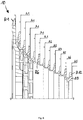
- the directions used in the following right / left, up / down and back / front relate to a bicycle viewed in the direction of travel (cf. Figure 1 ).
- the directions inside / outside refer to the center of the bike.
- Axial refers to the central axis of the multiple-pinion arrangement.
- the smaller-diameter pinions with a smaller number of teeth of the multiple-pinion arrangement are arranged axially further to the right or further out (also called “outboard") than the larger-diameter pinions with a larger number of teeth.
- the larger pinions are arranged axially further to the left or further inside (also called "inboard") than the smaller pinions.
- the smaller chainring of the front chainring arrangement is arranged further to the left or further inwards than the large chainring.
- the teeth are arranged radially on the outside of the pinion and the chainring.
- FIG. 1 shows a bicycle 1 with a multiple pinion arrangement 10 according to the invention and a bicycle drive according to the invention.
- the bicycle drive consists of a front chainring arrangement 30, which comprises a small chainring 31 and a large chainring 32, a rear multiple-sprocket arrangement 10 and a bicycle chain 20.
- the multiple-sprocket arrangement 10 consists of an increased number of at least ten adjacent sprockets R1 -R10, in particular twelve pinions R1-R12.
- the pinions R of the pinion arrangement 10 have different numbers of teeth and are arranged at a predetermined distance A from one another.
- the specified distances A are of different sizes and can be divided into the smallest distances A1 and larger distances A2-A7.
- the bicycle chain 20 is in engagement with the teeth of one of the chainrings, in the case shown the large chainring 32 of the chainring arrangement 30 and the teeth 11 of one of the adjacent sprockets RN of the multiple sprocket arrangement 10.
- power is transmitted from the front chainring arrangement 30 to the rear multiple-sprocket arrangement 10.
- a front derailleur FD moves the bicycle chain 20 when shifting from one chainring to the other chainring.
- a rear derailleur or the rear derailleur RD moves the bicycle chain 20 when shifting from a sprocket RN to the next smaller sprocket RN + 1 or to the next larger sprocket RN-1.
- the front derailleur FD and / or rear derailleur RD can be operated either mechanically or electrically. In the exemplary embodiment shown, both the front derailleur FD and the rear derailleur RD can be operated electrically. With one or more switching devices 40 mounted on the handlebar, the rear electrical switching mechanism RD and / or the front electrical derailleur FD is controlled wirelessly. In a chainring arrangement with only one chainring, the front derailleur is not required.
- the rear derailleur RD can start each of the pinions R1-R12 cleanly, despite the differently large pinion distances A, a corresponding switching protocol is stored in the control unit of the rear derailleur in the case of an electrically controlled rear derailleur, which reflects the different distances A.
- the geometry of the switching lever mechanism in particular the teeth of the switching disks located therein and / or the geometry of the switching mechanism fin, would be adapted to the differently large distances.
- the switching device according to the invention is not only suitable for a racing bike shown, but can also be used on a large number of types of bike, such as mountain bikes, touring bikes or e-bikes.
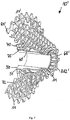
- FIG. 2 shows a schematic representation of a bicycle drive to illustrate the chain skew.
- the front chainring arrangement 30 comprises a smaller chainring 31 and a larger chainring 32.
- the multiple-sprocket arrangement 10 comprises twelve sprockets (R1-R12), the sprocket R1 being the largest-diameter sprocket and the sprocket R12 being the smallest-diameter sprocket.
- the chainring arrangement 30 is oriented in relation to the multiple sprocket arrangement 10 such that a neutral chain line KL0 is present when the chain is in mesh with the small chainring 31 and the sixth largest sprocket R6.
- the neutral chain line KL0 corresponds roughly to the ideal course of the chain, in which there is almost no chain skew.
- the meshing front chainring is in alignment with the meshing rear sprocket.
- the forces can be optimally transferred from the chainring to the sprocket.
- a particularly strong deflection of the chain from this neutral chain line KL0 or a particularly strong one Chain skew occurs when the chain meshes with the largest sprocket R1 or the smallest sprocket R12.
- the chain line KLR12 from the small chainring 31 to the smallest sprocket R12, is particularly critical because it represents the strongest skew of all possible chain runs of the drive. In addition, on the smaller sprockets there is also the risk that the inclined chain collides with the next larger sprocket. The inventive distance distribution counteracts this.
- the neutral chain line KL0 divides the pinion package 10 with its twelve pinions R1-R12 into five pinions R1-R5 located further inside or to the left with larger diameters and six further outside or right-lying pinions R7-R12 with smaller diameters. If the chain is in engagement with the large, further outwardly located sprocket 32, the neutral chain line KL0 also shifts outwards, for example onto the pinion R7. Correspondingly, the particularly critical skew on the smallest pinion R12 is somewhat less pronounced.
- a bicycle drive according to the invention can consist of a combination of one, two or three front chain rings and ten, eleven, twelve, thirteen or fourteen pinions.
- the neutral chain line KL0 is defined on the smallest of the chainrings because the chain skew is more pronounced on this than on the larger chainrings.
- the front sprocket arrangement 30 cannot be displaced outward at will with respect to the multiple sprocket arrangement 10. On the one hand, this would increase the chain skew on the largest sprocket.
- the position of the crank would also shift with the sprocket arrangement.
- the crank should be as close as possible to the bicycle frame, i.e. as far inside as possible.
- a crank positioned far on the outside would increase the risk that the pedal on the inside of the curve would touch down in tight and fast corners.
- the sprockets to the right of the neutral chain line KL0 are ideally arranged at greater distances from one another than the sprockets to the left of the chain line KL0.
- the pinions are positioned to the left of the neutral chain line KL0 at the smallest possible distances, in particular the smallest possible distances from one another.
- further measures can be taken in particular on the largest sprockets R1 and R2 Figure 4 is received.
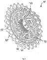
- FIG 3 shows a perspective partial sectional view of a first embodiment of the multiple pinion arrangement 10 according to the invention.
- the pinion package 10 comprises twelve adjacent pinions (R1-R12) with different diameters and the associated different numbers of teeth.
- the largest pinion R1 is in torque-transmitting engagement with the driver 50, which further transmits the torque to a rear wheel hub, not shown here.
- the pinion R1 has an engagement profile 15 which is brought into engagement with a counterpart on the driver 50.
- the multiple pinion arrangement 10 is pushed onto the driver 50 until the largest pinion R1 rests against the driver stop 51 with a stop region located radially further inward.
- the adapter 60 is screwed with its internal thread 65 onto the corresponding external thread of the driver 50 and fixes the multiple pinion arrangement 10 on the driver 50 in the axial direction.
- the adapter 60 is fastened, in particular screwed, to the driver 50 on the one hand, so that the largest pinion R1 is fixed between the driver stop 51 and the inner end of the adapter 60.
- the adapter 60 with its snap protrusions 68 engages behind a corresponding counter snap protrusion on the smallest pinion R12 of the multiple pinion arrangement 10 and thus axially fixes the pinion package 10 relative to the driver 50.
- the pinions R2 to R11 are made in one piece, in particular milled from one piece, and have a conical shape.
- the largest pinion R1 is manufactured separately and connected to the remaining pinions R2-R11 to transmit torque.
- the largest sprocket R1 is to save weight, especially made of aluminum manufactured.
- the largest pinion R1 is attached to the pinion R2 by means of a plug connection.
- the pinion pack 10 is supported radially on the driver 50 or on the adapter 60 in the area of the largest pinion R1 and in the area of the smallest pinion R10-R12. In between, the pinion pack 10 is designed to be self-supporting.
- the largest pinion R1 is cranked and thus follows the course of the spokes, due to which the pinion R1 has more axial space available radially on the outside (in the area of the teeth) than on the radial inside (in the area of the driver).
- the smallest pinions R11 and R12 have a smaller inner diameter than the outer diameter of the driver 50 and are arranged further outward in the axial direction than the driver 50.
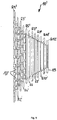
- FIG. 10 is an interior perspective view of the first embodiment of the multiple sprocket assembly 10 of FIG Figure 3 , but without the driver 50.
- the adapter 60 with its internal thread 65 can be clearly seen.
- the torque transmission from the pinion package 10 to the driver 50 takes place exclusively in the area of the profile 15 of the largest pinion R1.
- the sequence of thin teeth 12 and thick teeth 13 can also be clearly seen. Thick and thin refers to the material thickness of the teeth 11 measured in the axial direction.
- the teeth 12, 13 only thicken and thin in one axial direction, namely in the direction of the inside of the first pinion R1. This means that the outside of the pinion R1 remains evenly flat (cf. Fig. 3 ), which makes it easier to attach shift gates.
- the improved chain guide weakens the negative consequences of chain skew on the large sprockets. In particular, the vibration of the chain and the associated noise generation are reduced.
- the largest pinion R1 has an even number of here 28 teeth 11, so that a repeated sequence of thin teeth 12 and thick teeth 13 is possible along the entire circumference.
- the chain skew is particularly strong on the two largest sprockets R1 and R2, which is why an improved chain guide is of particular importance.
- thin and thick teeth could alternately appear on other pinions.
- the teeth 11 of the largest pinion R1 additionally have rounded sliding bevels 14 on the inside. This means that the transition between the sliding bevel 14 located on the tooth tip and the tooth body runs tangentially, that is to say without an edge.
- the rounded slip-off bevels 14 on the inside of the pinion are in turn particularly important on the largest pinions, on which the chain skew is particularly pronounced. Therefore, the second largest pinion R2, which is not visible here, also has these sliding bevels (cf. Fig. 5 ).
- FIG. 12 shows an enlarged sectional view of the multiple-pinion arrangement 10 from FIG Figure 3 .
- the axial fixing of the multiple pinion arrangement 10 relative to the driver 50 with the aid of the adapter 60 can be clearly seen.
- the snap lugs 68 at the outer end of the adapter 60 engage behind a corresponding projection on the smallest pinion R12.
- the largest pinion R1 is fixed between the driver stop 51 and the inner end of the adapter 60. Due to the offset of the largest pinion R1, the axial width B1 of the multiple pinion arrangement 10 in the area of the driver 50 (radially inside) is smaller than the axial width B2 in the area of the teeth (radially outside).
- the width B1 is smaller than the specified installation space between the driver stop 51 and a frame stop, not shown here.
- the specified installation space varies depending on which driver standard is used.
- the axial width B1 of the multiple pinion arrangement 10 is between 37 mm and 42 mm, in particular between 40 mm and 41 mm.
- the axial width B2 in the area of the teeth of the largest pinion R1 is between 42 mm and 43 mm.
- Two adjacent pinions RN, RN + 1 of the twelve pinions R1-R12 are arranged at a predetermined distance A from one another.
- the distances A are each measured from the outside of a pinion RN to the outside of the adjacent next smaller pinion RN + 1.
- These eleven distances A can either be assigned to a smallest distance or larger distances.
- a distance A includes not only the free space between two adjacent pinions, but also the pinion thickness of the smaller of the two pinions.
- the axial thickness of the pinions R1 to R12 can be constant or vary.
- the torque-transmitting pinion R1 and the pinion R2 are slightly thicker than the pinions R3 to R11.
- the pinion R1 and pinion R2 have teeth 11, which are designed as thin teeth 12 and thick teeth 13. In the case shown, this thickening of the teeth 13 only takes place on the inside of the pinions R1 and R2 and is not visible to the outside (cf. Figure 4 ).
- the smallest pinion R12 also has a bead 19 in the area of the root circle. This bead 19 presses a bicycle chain, which engages in the smallest sprocket R12, further outward in the axial direction and thereby reduces the consequences of the chain skew.
- R1 corresponds to 2.6 mm
- R2 corresponds to 2.4 mm
- R3 to R11 correspond to 1.55 mm
- R12 corresponds to 1.75 mm.
- the bead 19 preferably has a dimension of 0.4 mm.
- Pinions R1 and R2 have a larger size due to the thick teeth 13.
- At least some of the pinions R1 to R5 or the connecting pieces between the pinions R1 to R5 have material recesses 17.
- FIG. 10 shows the section of the multiple pinion arrangement 10 from FIG Fig. 5 without the driver and adapter.
- the eleven distances A described above between two adjacent pinions RN, RN + 1 can be assigned either to a smallest distance A1 or larger distances A2-A6.
- the pinions R1 to R12 are arranged at the following distances A from one another: A1-A1-A1-A1-A1-A2-A3-A4-A5-A6-A5.
- the six largest pinions R1 to R6 are accordingly arranged at a constant smallest distance A1 from one another.
- the remaining pinions R7 to R12 are then spaced apart from one another by a greater distance A2-A6.
- the larger distances A2 to A6 are not constant and therefore have different reference symbols A2 to A6. All larger distances A2 to A6 have a larger dimension than the smallest distances A1.
- five are the smallest distances A1 and six are the larger distances A2-A6. This leads to a distance ratio of 5: 6 or, in other words, to a proportion of the smallest distances A1 of 45.45% and a proportion of larger distances A2-A6 of 54.55%.
- the proportion of the smallest distances A1 is below the required maximum values of 70%, 60% and 50%.
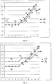
- This distance distribution of the multiple pinion arrangement 10 is also shown as graph a) in the diagram in FIG Figure 10 shown.
- the five smallest distances A1 in the graph in Figures 10 and 11 are each labeled only once with the reference symbol A1 for better clarity.
- the five smallest distances A1 in each of the variants a) to d) have a constant dimension.
- FIG. 7 shows a perspective partial sectional view of a second embodiment of the multiple pinion arrangement 10 'according to the invention, which largely corresponds to the first embodiment. Unchanged parts therefore have the same reference symbols and, exactly like their interaction, are not described again.
- the pinion pack 10 ' also includes twelve adjacent pinions (R1'-R12') with differently large diameters and the associated different numbers of teeth.
- the largest pinion R1 ' is not in torque-transmitting engagement with the driver 50, but a separate component 70.
- the torque-transmitting component 70 has an engagement profile 75 along its inner diameter, which with a counterpart on the driver 50 in Intervention is brought about.
- the component 70 also has a further engagement profile 72 on its outer diameter, which is brought into engagement with the multiple-pinion arrangement 10 '.
- the profile 72 engages in the connection area between the second pinion R2 'and the third pinion R3'.
- the entire torque of the multiple pinion arrangement 10 ′ is thus transmitted to the driver 50 via the component 70 in the area of the second and third pinion R2 ′ / R3 ′.
- the component 70 also serves as a radial support for the pinion arrangement 10 'on the driver 50.
- the component 70 is axially fixed between the driver stop 51 and the inner end of the adapter 60'.
- the adapter 60 ' differs from the first embodiment in that, instead of flexible snap projections 68, it has a closed and therefore rigid outer end diameter 68' which is smaller than the inner diameter of the smallest pinion R12 '.
- An additional securing ring, not visible here, in particular a snap ring, with a larger outer diameter than the inner diameter of the smallest pinion R12 ' is placed in a circumferential groove of the outer adapter end and axially fixes the multiple pinion arrangement 10' relative to the driver 50.
- All pinions R1 'to R12' are made in one piece, in particular milled from one piece, and have a conical shape.
- the pinion pack 10 ' is supported radially on the driver 50 or on the adapter 60 in the area of the second and third pinion R2' / R3 'and in the area of the smallest pinion R10'-R12'. In between, the pinion pack 10 'is designed to be self-supporting.
- FIG. 13 is an interior perspective view of the second embodiment of the multiple sprocket assembly 10 'of FIG Fig. 7 , but without the driver 50, so that the engagement profile 75 of the torque-transmitting component 70 is visible.
- the larger pinions R1-R4 have material recesses 17 '.
- the torque-transmitting component 70 likewise has material recesses 77.
- the component 70 is made of aluminum.
- Figure 9 Figure 3 is a sectional view of the second embodiment of the multiple sprocket assembly 10 'without the driver and adapter.
- the twelve pinions R1'-R12 ' are also positioned at eleven predetermined distances A from one another. These distances can be assigned either the smallest distances A1 or larger distances A2.
- the pinion thickness is 1.9 mm on the largest pinion R1 ', 1.6 mm on the pinions R2' to R11 'and 1.8 mm on the smallest pinion R12'.
- a bead 19 with a dimension of 0.3 mm can also be arranged on the smallest pinion R12 '.
- a multiple pinion arrangement according to the invention can have various distance distributions according to the claims. Exemplary distance distributions can be found in graphs a), b), c) and d) in Figure 10, 11 and 12th evident.
- Graph b shows a further variant of the distance distribution, with five of the eleven distances again being attributable to the smallest distances A1, and thus making up a share of 45.45%.
- the dimension of the smallest distances A1 is 3.5 mm here.
- the remaining six spaces are to be assigned to the larger spaces A2-A5.
- the larger distance A2 is 3.55 mm.
- the last distance decreases again due to the bead 19 the distance A4 with 3.75 mm.
- a larger final distance A6 of 3.95 mm could also be provided.
- the distance A between the first and second pinion is a larger distance A2 and not, as in the other variants, a smallest distance A1. This may be necessary due to the construction. Particularly in the case of one-piece pinion packs, as shown in the second embodiment, a smallest distance A1 would also be possible instead of the larger distance A2.
- the variant d) in Figure 11 shows a further embodiment of the distance distribution with five smallest distances A1 between the six largest pinions R1-R6. This is followed by four constantly larger distances A2 between the pinions R6 to R10.
- the three smallest pinions R10, R11 and R12 are then positioned at linearly increasing distances A3 and A4.
- the five smallest distances A1 each correspond to a dimension of 3.6 mm
- the four larger distances A2 each correspond to a dimension of 3.7 mm
- the larger distance A4 to a dimension of 3.8 mm
- the larger distance A5 to a dimension of 3.9 mm.
- FIG 12 Another possible distance distribution for a multiple pinion arrangement with thirteen pinions R1-R13 and correspondingly twelve distances A is shown.
- the largest pinions R1 to R7 are each arranged at the smallest distance A1.
- these six smallest distances A1 each correspond to a dimension of 3.45 mm.
- the narrow design in the area of the larger pinions saves space.
- the remaining sprockets R8 to R13 are then arranged at larger distances A2-A6 from one another and thereby reduce the consequences of chain skew on the smaller sprockets.
- the larger distances A2-A6 do not increase linearly.
- A2 corresponds to a dimension of 3.5 mm, A3 to a dimension of 3.55 mm, A4 to a dimension of 3.65 mm, A5 to a dimension of 3.75 mm and A6 to a dimension of 3.85 mm.
- the smallest pinion R13 is then again arranged at a greater distance A5. This is again due to a possible bead on the smallest pinion R13.
- the bead could be omitted and the last distance increased further to a larger distance A7 of 3.95 mm.
- the smallest distances must be a minimum. This minimum corresponds, because from the outer surface of a pinion to the outer surface of the next smaller pinion, at least the sum of the axial thickness of the next smaller pinion, the thickness of an inner link plate and the thickness of an outer link plate.
- a chain that is suitable for use with a multiple sprocket arrangement with an increased number of at least ten sprockets is designed to be particularly narrow.
- the thickness of the inner link plate and the outer link plate could have the same dimension of 0.75 mm or 0.8 mm in each case.
- the narrower pinions of the exemplary embodiments which have a dimension of 1.55 mm, a minimum distance of 3.05 mm results (1.55 mm plus 0.75 mm plus 0.75 mm).
- the narrower pinions have a dimension of 1.6 mm.
- With the same link plate thickness of 0.8 mm there is a minimum distance of 3.2 mm (1.6 mm plus 0.8 mm plus 0.8 mm).
- the theoretical minimum distance forms the basis for calculating the smallest distance A1, which in the variants shown is between 3.45 mm and 3.6 mm. In fact, the calculation of the smallest distance A1 depends heavily on the chain used and its exact geometry and dimensions. All dimensions are subject to the usual manufacturing tolerances.
Landscapes
- Engineering & Computer Science (AREA)
- Chemical & Material Sciences (AREA)
- Combustion & Propulsion (AREA)
- Transportation (AREA)
- Mechanical Engineering (AREA)
- Gears, Cams (AREA)
Applications Claiming Priority (2)
| Application Number | Priority Date | Filing Date | Title |
|---|---|---|---|
| DE102016012229.3A DE102016012229A1 (de) | 2016-10-13 | 2016-10-13 | Mehrfach-Ritzelanordnung und Fahrradantrieb mit einer solchen Mehrfach-Ritzelanordnung |
| EP17001645.5A EP3309052B1 (fr) | 2016-10-13 | 2017-10-06 | Dispositif à plusieurs pignons et entraînement par roue porteuse doté d'un tel dispositif à plusieurs pignons |
Related Parent Applications (1)
| Application Number | Title | Priority Date | Filing Date |
|---|---|---|---|
| EP17001645.5A Division EP3309052B1 (fr) | 2016-10-13 | 2017-10-06 | Dispositif à plusieurs pignons et entraînement par roue porteuse doté d'un tel dispositif à plusieurs pignons |
Publications (2)
| Publication Number | Publication Date |
|---|---|
| EP3792171A1 true EP3792171A1 (fr) | 2021-03-17 |
| EP3792171B1 EP3792171B1 (fr) | 2023-08-23 |
Family
ID=60042937
Family Applications (2)
| Application Number | Title | Priority Date | Filing Date |
|---|---|---|---|
| EP20000349.9A Active EP3792171B1 (fr) | 2016-10-13 | 2017-10-06 | Dispositif à plusieurs pignons et entraînement par roue porteuse doté d'un tel dispositif à plusieurs pignons |
| EP17001645.5A Active EP3309052B1 (fr) | 2016-10-13 | 2017-10-06 | Dispositif à plusieurs pignons et entraînement par roue porteuse doté d'un tel dispositif à plusieurs pignons |
Family Applications After (1)
| Application Number | Title | Priority Date | Filing Date |
|---|---|---|---|
| EP17001645.5A Active EP3309052B1 (fr) | 2016-10-13 | 2017-10-06 | Dispositif à plusieurs pignons et entraînement par roue porteuse doté d'un tel dispositif à plusieurs pignons |
Country Status (5)
| Country | Link |
|---|---|
| US (1) | US11034412B2 (fr) |
| EP (2) | EP3792171B1 (fr) |
| CN (1) | CN107933811B (fr) |
| DE (1) | DE102016012229A1 (fr) |
| TW (1) | TWI756265B (fr) |
Families Citing this family (13)
| Publication number | Priority date | Publication date | Assignee | Title |
|---|---|---|---|---|
| DE102017000855A1 (de) * | 2017-01-31 | 2018-08-02 | Sram Deutschland Gmbh | Mehrfach-Ritzelanordnung mit Schweißverbindung |
| IT201700015311A1 (it) * | 2017-02-13 | 2018-08-13 | Campagnolo Srl | Assieme di ruote dentate per pacco pignoni |
| US10625821B2 (en) * | 2017-03-17 | 2020-04-21 | Shimano Inc. | Bicycle sprocket and bicycle sprocket assembly |
| IT201700115411A1 (it) | 2017-10-13 | 2019-04-13 | Campagnolo Srl | Corpetto per mozzo di ruota posteriore di bicicletta e pacco pignoni atto ad essere montato sul mozzo mediante tale corpetto |
| IT201700115407A1 (it) * | 2017-10-13 | 2019-04-13 | Campagnolo Srl | Pacco pignoni e corpetto per il suo montaggio su un mozzo di ruota posteriore di bicicletta |
| EP3533701B1 (fr) * | 2018-02-28 | 2021-01-20 | SRAM Deutschland GmbH | Dispositif pignon de roue arrière pourvu de deux dispositif partiels d'une seule pièce raccordés afin de tourner ensemble |
| CN108583771B (zh) * | 2018-05-28 | 2023-09-12 | 湖南耐特材料科技有限公司 | 一种一体式飞轮 |
| DE102020005373A1 (de) * | 2020-09-01 | 2022-03-03 | Sram Deutschland Gmbh | Mehrfachritzelanordnung für eine Hinterradbaugruppe für ein Fahrrad und Hinterradbaugruppe |
| EP3960606A1 (fr) * | 2020-09-01 | 2022-03-02 | SRAM Deutschland GmbH | Module à pignons multiples et module de roue arrière pour une bicyclette à dérailleur |
| US11529827B2 (en) * | 2020-12-10 | 2022-12-20 | Tien Hsin Industries Co., Ltd. | Transmission assembly of a bicycle |
| US11603166B2 (en) * | 2021-04-29 | 2023-03-14 | Shimano Inc. | Rear sprocket assembly and lock device |
| US11858588B2 (en) * | 2021-04-29 | 2024-01-02 | Shimano Inc. | Rear sprocket assembly and lock device |
| US11767080B1 (en) * | 2022-07-15 | 2023-09-26 | Shimano Inc. | Rear sprocket assembly |
Citations (5)
| Publication number | Priority date | Publication date | Assignee | Title |
|---|---|---|---|---|
| US3478614A (en) | 1966-11-17 | 1969-11-18 | Shimano Industrial Co | Multistage sprocket wheel assembly for a bicycle of speed change type |
| US5954604A (en) | 1996-11-21 | 1999-09-21 | Shimano, Inc. | Multiple sprocket assembly for a bicycle |
| EP2022712A2 (fr) | 2007-08-09 | 2009-02-11 | CAMPAGNOLO S.r.l. | Système de transmission de mouvement d'une bicyclette |
| DE102011010855A1 (de) | 2011-02-10 | 2012-08-16 | Sram Deutschland Gmbh | Dämpfungseinrichtung an einer Mehrfach-Kettenradanordnung |
| DE202016100725U1 (de) | 2016-02-12 | 2016-04-22 | Shimano Inc. | Fahrrad-Nabenbaueinheit |
Family Cites Families (10)
| Publication number | Priority date | Publication date | Assignee | Title |
|---|---|---|---|---|
| US7247108B2 (en) * | 2002-05-14 | 2007-07-24 | Shimano, Inc. | Method and apparatus for controlling an automatic bicycle transmission |
| US6923741B2 (en) * | 2002-08-30 | 2005-08-02 | Shimano Inc. | Top sprocket for a rear sprocket assembly and rear sprocket assembly for a bicycle |
| US7585240B2 (en) * | 2005-02-03 | 2009-09-08 | Shimano Inc. | Bicycle sprocket assembly |
| TWI701186B (zh) * | 2011-07-13 | 2020-08-11 | 德商矢倫德國股份有限公司 | 支載腳踏車變速器所用之備有小鏈輪的多鏈輪配置的傳動座體裝置 |
| US9533735B2 (en) * | 2013-07-19 | 2017-01-03 | Sram Deutschland Gmbh | Multiple-sprocket arrangement for a bicycle gearing |
| US9581229B2 (en) * | 2014-02-10 | 2017-02-28 | Wolf Tooth Components, LLC | Sprocket |
| DE102015219522A1 (de) * | 2014-10-14 | 2016-04-14 | Sram Deutschland Gmbh | Mehrfach-Kettenradanordnung für eine Hinterradnabe |
| DE202015009220U1 (de) * | 2014-12-15 | 2016-12-08 | Shimano Inc. | Fahrradmehrfachkettenradanordnung und Antriebsabschnitt |
| US9599208B2 (en) * | 2015-02-12 | 2017-03-21 | Sram, Llc | Chainrings and crank assemblies |
| US20160236750A1 (en) * | 2015-02-13 | 2016-08-18 | Shimano Inc. | Bicycle drive system |
-
2016
- 2016-10-13 DE DE102016012229.3A patent/DE102016012229A1/de not_active Withdrawn
-
2017
- 2017-09-15 TW TW106131753A patent/TWI756265B/zh active
- 2017-10-06 EP EP20000349.9A patent/EP3792171B1/fr active Active
- 2017-10-06 EP EP17001645.5A patent/EP3309052B1/fr active Active
- 2017-10-10 CN CN201710933395.4A patent/CN107933811B/zh active Active
- 2017-10-13 US US15/783,771 patent/US11034412B2/en active Active
Patent Citations (5)
| Publication number | Priority date | Publication date | Assignee | Title |
|---|---|---|---|---|
| US3478614A (en) | 1966-11-17 | 1969-11-18 | Shimano Industrial Co | Multistage sprocket wheel assembly for a bicycle of speed change type |
| US5954604A (en) | 1996-11-21 | 1999-09-21 | Shimano, Inc. | Multiple sprocket assembly for a bicycle |
| EP2022712A2 (fr) | 2007-08-09 | 2009-02-11 | CAMPAGNOLO S.r.l. | Système de transmission de mouvement d'une bicyclette |
| DE102011010855A1 (de) | 2011-02-10 | 2012-08-16 | Sram Deutschland Gmbh | Dämpfungseinrichtung an einer Mehrfach-Kettenradanordnung |
| DE202016100725U1 (de) | 2016-02-12 | 2016-04-22 | Shimano Inc. | Fahrrad-Nabenbaueinheit |
Also Published As
| Publication number | Publication date |
|---|---|
| CN107933811B (zh) | 2021-06-08 |
| TWI756265B (zh) | 2022-03-01 |
| EP3309052A1 (fr) | 2018-04-18 |
| EP3309052B1 (fr) | 2020-09-30 |
| TW201819248A (zh) | 2018-06-01 |
| EP3792171B1 (fr) | 2023-08-23 |
| CN107933811A (zh) | 2018-04-20 |
| US20180105229A1 (en) | 2018-04-19 |
| US11034412B2 (en) | 2021-06-15 |
| DE102016012229A1 (de) | 2018-04-19 |
Similar Documents
| Publication | Publication Date | Title |
|---|---|---|
| EP3309052B1 (fr) | Dispositif à plusieurs pignons et entraînement par roue porteuse doté d'un tel dispositif à plusieurs pignons | |
| DE102012025875B3 (de) | Fahrradkettenring für eine Fahrradkurbelanordnung zum Eingreifen in eine Antriebskette | |
| EP3009339B1 (fr) | Systeme de roue d'entrainement multiple pour un moyeu de roue arriere | |
| EP2497705B1 (fr) | Unité d'entraînement sur la roue arrière d'un vélo | |
| EP2684790B1 (fr) | Galet guide-chaîne pour un dérailleur arrière d'une chaîne de bicyclette et dérailleur arrière doté d'un tel galet guide-chaîne | |
| DE102010027228B4 (de) | Mehrfach-Ritzelanordnung für Fahrräder | |
| EP3181439B1 (fr) | Anneau pour fil de chaine | |
| EP3960611B1 (fr) | Système d'entraînement d'un vélo comprenant un système de plateau de pédalier multiple | |
| EP2039602B1 (fr) | Unité de roue à plusieurs chaînes pour vélos | |
| EP3354553B1 (fr) | Dispositif de pignons multiples à assemblage par soudure | |
| EP3501962B1 (fr) | Roue dentée simple | |
| EP3339158B1 (fr) | Pignon, dispositif à plusieurs pignons et entraînement par roue porteuse doté d'un tel dispositif à plusieurs pignons | |
| DE102015205736A1 (de) | Fahrrad-Hinterrad-Ritzelanordnung | |
| EP3450297A1 (fr) | Support de roue à chaîne et dispositif de roue à chaînes multiples | |
| EP3567276B1 (fr) | Languette intérieure asymétrique de chaîne de bicyclette, languette extérieure de chaîne de bicyclette et chaîne de bicyclette dotée d'au moins une telle languette | |
| EP3318335A1 (fr) | Chaînes à rouleau pour cycle | |
| DE102010009067B4 (de) | Zahnkettentrieb | |
| DE2945271A1 (de) | Kettenschaltgetriebe | |
| DE19629602A1 (de) | Kettentrieb für Fahrräder | |
| DE102010064733B4 (de) | Mehrfach-Ritzelanordnung für Fahrräder | |
| DE102021101223A1 (de) | Stärker verschleißfeste Fahrradritzelpaarung und Ritzelkassette mit einer solchen |
Legal Events
| Date | Code | Title | Description |
|---|---|---|---|
| PUAI | Public reference made under article 153(3) epc to a published international application that has entered the european phase |
Free format text: ORIGINAL CODE: 0009012 |
|
| STAA | Information on the status of an ep patent application or granted ep patent |
Free format text: STATUS: THE APPLICATION HAS BEEN PUBLISHED |
|
| AC | Divisional application: reference to earlier application |
Ref document number: 3309052 Country of ref document: EP Kind code of ref document: P |
|
| AK | Designated contracting states |
Kind code of ref document: A1 Designated state(s): AL AT BE BG CH CY CZ DE DK EE ES FI FR GB GR HR HU IE IS IT LI LT LU LV MC MK MT NL NO PL PT RO RS SE SI SK SM TR |
|
| STAA | Information on the status of an ep patent application or granted ep patent |
Free format text: STATUS: REQUEST FOR EXAMINATION WAS MADE |
|
| 17P | Request for examination filed |
Effective date: 20210913 |
|
| GRAP | Despatch of communication of intention to grant a patent |
Free format text: ORIGINAL CODE: EPIDOSNIGR1 |
|
| STAA | Information on the status of an ep patent application or granted ep patent |
Free format text: STATUS: GRANT OF PATENT IS INTENDED |
|
| INTG | Intention to grant announced |
Effective date: 20230412 |
|
| GRAS | Grant fee paid |
Free format text: ORIGINAL CODE: EPIDOSNIGR3 |
|
| GRAA | (expected) grant |
Free format text: ORIGINAL CODE: 0009210 |
|
| STAA | Information on the status of an ep patent application or granted ep patent |
Free format text: STATUS: THE PATENT HAS BEEN GRANTED |
|
| AC | Divisional application: reference to earlier application |
Ref document number: 3309052 Country of ref document: EP Kind code of ref document: P |
|
| AK | Designated contracting states |
Kind code of ref document: B1 Designated state(s): AL AT BE BG CH CY CZ DE DK EE ES FI FR GB GR HR HU IE IS IT LI LT LU LV MC MK MT NL NO PL PT RO RS SE SI SK SM TR |
|
| REG | Reference to a national code |
Ref country code: GB Ref legal event code: FG4D Free format text: NOT ENGLISH |
|
| REG | Reference to a national code |
Ref country code: CH Ref legal event code: EP |
|
| P01 | Opt-out of the competence of the unified patent court (upc) registered |
Effective date: 20230801 |
|
| REG | Reference to a national code |
Ref country code: DE Ref legal event code: R096 Ref document number: 502017015284 Country of ref document: DE |
|
| REG | Reference to a national code |
Ref country code: IE Ref legal event code: FG4D Free format text: LANGUAGE OF EP DOCUMENT: GERMAN |
|
| REG | Reference to a national code |
Ref country code: NL Ref legal event code: FP |
|
| PGFP | Annual fee paid to national office [announced via postgrant information from national office to epo] |
Ref country code: NL Payment date: 20231019 Year of fee payment: 7 |
|
| REG | Reference to a national code |
Ref country code: LT Ref legal event code: MG9D |
|
| PG25 | Lapsed in a contracting state [announced via postgrant information from national office to epo] |
Ref country code: GR Free format text: LAPSE BECAUSE OF FAILURE TO SUBMIT A TRANSLATION OF THE DESCRIPTION OR TO PAY THE FEE WITHIN THE PRESCRIBED TIME-LIMIT Effective date: 20231124 |
|
| PG25 | Lapsed in a contracting state [announced via postgrant information from national office to epo] |
Ref country code: IS Free format text: LAPSE BECAUSE OF FAILURE TO SUBMIT A TRANSLATION OF THE DESCRIPTION OR TO PAY THE FEE WITHIN THE PRESCRIBED TIME-LIMIT Effective date: 20231223 |
|
| PG25 | Lapsed in a contracting state [announced via postgrant information from national office to epo] |
Ref country code: SE Free format text: LAPSE BECAUSE OF FAILURE TO SUBMIT A TRANSLATION OF THE DESCRIPTION OR TO PAY THE FEE WITHIN THE PRESCRIBED TIME-LIMIT Effective date: 20230823 Ref country code: RS Free format text: LAPSE BECAUSE OF FAILURE TO SUBMIT A TRANSLATION OF THE DESCRIPTION OR TO PAY THE FEE WITHIN THE PRESCRIBED TIME-LIMIT Effective date: 20230823 Ref country code: PT Free format text: LAPSE BECAUSE OF FAILURE TO SUBMIT A TRANSLATION OF THE DESCRIPTION OR TO PAY THE FEE WITHIN THE PRESCRIBED TIME-LIMIT Effective date: 20231226 Ref country code: NO Free format text: LAPSE BECAUSE OF FAILURE TO SUBMIT A TRANSLATION OF THE DESCRIPTION OR TO PAY THE FEE WITHIN THE PRESCRIBED TIME-LIMIT Effective date: 20231123 Ref country code: LV Free format text: LAPSE BECAUSE OF FAILURE TO SUBMIT A TRANSLATION OF THE DESCRIPTION OR TO PAY THE FEE WITHIN THE PRESCRIBED TIME-LIMIT Effective date: 20230823 Ref country code: LT Free format text: LAPSE BECAUSE OF FAILURE TO SUBMIT A TRANSLATION OF THE DESCRIPTION OR TO PAY THE FEE WITHIN THE PRESCRIBED TIME-LIMIT Effective date: 20230823 Ref country code: IS Free format text: LAPSE BECAUSE OF FAILURE TO SUBMIT A TRANSLATION OF THE DESCRIPTION OR TO PAY THE FEE WITHIN THE PRESCRIBED TIME-LIMIT Effective date: 20231223 Ref country code: HR Free format text: LAPSE BECAUSE OF FAILURE TO SUBMIT A TRANSLATION OF THE DESCRIPTION OR TO PAY THE FEE WITHIN THE PRESCRIBED TIME-LIMIT Effective date: 20230823 Ref country code: GR Free format text: LAPSE BECAUSE OF FAILURE TO SUBMIT A TRANSLATION OF THE DESCRIPTION OR TO PAY THE FEE WITHIN THE PRESCRIBED TIME-LIMIT Effective date: 20231124 Ref country code: FI Free format text: LAPSE BECAUSE OF FAILURE TO SUBMIT A TRANSLATION OF THE DESCRIPTION OR TO PAY THE FEE WITHIN THE PRESCRIBED TIME-LIMIT Effective date: 20230823 |
|
| PGFP | Annual fee paid to national office [announced via postgrant information from national office to epo] |
Ref country code: FR Payment date: 20231026 Year of fee payment: 7 Ref country code: DE Payment date: 20231031 Year of fee payment: 7 |
|
| PG25 | Lapsed in a contracting state [announced via postgrant information from national office to epo] |
Ref country code: PL Free format text: LAPSE BECAUSE OF FAILURE TO SUBMIT A TRANSLATION OF THE DESCRIPTION OR TO PAY THE FEE WITHIN THE PRESCRIBED TIME-LIMIT Effective date: 20230823 |
|
| PG25 | Lapsed in a contracting state [announced via postgrant information from national office to epo] |
Ref country code: ES Free format text: LAPSE BECAUSE OF FAILURE TO SUBMIT A TRANSLATION OF THE DESCRIPTION OR TO PAY THE FEE WITHIN THE PRESCRIBED TIME-LIMIT Effective date: 20230823 |
|
| PG25 | Lapsed in a contracting state [announced via postgrant information from national office to epo] |
Ref country code: SM Free format text: LAPSE BECAUSE OF FAILURE TO SUBMIT A TRANSLATION OF THE DESCRIPTION OR TO PAY THE FEE WITHIN THE PRESCRIBED TIME-LIMIT Effective date: 20230823 Ref country code: RO Free format text: LAPSE BECAUSE OF FAILURE TO SUBMIT A TRANSLATION OF THE DESCRIPTION OR TO PAY THE FEE WITHIN THE PRESCRIBED TIME-LIMIT Effective date: 20230823 Ref country code: ES Free format text: LAPSE BECAUSE OF FAILURE TO SUBMIT A TRANSLATION OF THE DESCRIPTION OR TO PAY THE FEE WITHIN THE PRESCRIBED TIME-LIMIT Effective date: 20230823 Ref country code: EE Free format text: LAPSE BECAUSE OF FAILURE TO SUBMIT A TRANSLATION OF THE DESCRIPTION OR TO PAY THE FEE WITHIN THE PRESCRIBED TIME-LIMIT Effective date: 20230823 Ref country code: DK Free format text: LAPSE BECAUSE OF FAILURE TO SUBMIT A TRANSLATION OF THE DESCRIPTION OR TO PAY THE FEE WITHIN THE PRESCRIBED TIME-LIMIT Effective date: 20230823 Ref country code: CZ Free format text: LAPSE BECAUSE OF FAILURE TO SUBMIT A TRANSLATION OF THE DESCRIPTION OR TO PAY THE FEE WITHIN THE PRESCRIBED TIME-LIMIT Effective date: 20230823 Ref country code: SK Free format text: LAPSE BECAUSE OF FAILURE TO SUBMIT A TRANSLATION OF THE DESCRIPTION OR TO PAY THE FEE WITHIN THE PRESCRIBED TIME-LIMIT Effective date: 20230823 |