EP3792158A1 - Rotary active side air curtain assembly for a motor vehicle - Google Patents
Rotary active side air curtain assembly for a motor vehicle Download PDFInfo
- Publication number
- EP3792158A1 EP3792158A1 EP19207878.0A EP19207878A EP3792158A1 EP 3792158 A1 EP3792158 A1 EP 3792158A1 EP 19207878 A EP19207878 A EP 19207878A EP 3792158 A1 EP3792158 A1 EP 3792158A1
- Authority
- EP
- European Patent Office
- Prior art keywords
- air curtain
- side air
- active side
- curtain assembly
- rotating shaft
- Prior art date
- Legal status (The legal status is an assumption and is not a legal conclusion. Google has not performed a legal analysis and makes no representation as to the accuracy of the status listed.)
- Granted
Links
Images

Classifications
-
- B—PERFORMING OPERATIONS; TRANSPORTING
- B62—LAND VEHICLES FOR TRAVELLING OTHERWISE THAN ON RAILS
- B62D—MOTOR VEHICLES; TRAILERS
- B62D35/00—Vehicle bodies characterised by streamlining
Definitions
- the present invention relates to automotive exteriors, and more particularly, to a rotary active side air curtain assembly.
- the present invention provides a rotary active side air curtain assembly.
- the present invention provides a rotary active side air curtain assembly for a motr vehicle, comprising a wind guide element, a rotating element, and a driving mechanism, wherein the rotating element comprises a rotating shaft and a blade that are fixed to one another, the blade being mounted on the wind guide element through the rotating shaft, and wherein the driving mechanism is connected to the rotating shaft and can drive the rotating shaft to rotate so as to drive the blade to rotate between an open position and a closed position.
- the wind guide element is provided with a top part and a base part that are opposite to each other, and the rotating shaft is pivotably mounted between the top part and the base part.
- the base part is mounted with a baseplate which is provided with a mounting hole, and a bottom end of the rotating shaft is inserted pivotably into the mounting hole.
- the baseplate is a wear-resistant plate.
- a middle part of the baseplate is provided with a screw through hole, and a screw runs through the screw through hole to fasten the baseplate to the base part.
- the top part is provided with a mounting base in which the driving mechanism is mounted, and a top end of the rotating shaft pivotably runs through the top part and extends upward and is connected to the driving mechanism.
- the driving mechanism is connected to a body control module or an electronic control unit of a vehicle.
- the driving mechanism is an electrical motor.
- the rotary active side air curtain assembly according to the present invention, opening of the blade is accurately controlled by the driving mechanism and the rotating shaft and wind pressure in an area of the rotary active side air curtain is improved through the opening and closing of the blade, thus wind resistance of the entire vehicle is improved and the perfection of the entire vehicle styling is ensured.
- the rotary active side air curtain assembly according to the present invention not only allows to improve aerodynamic performance of the entire vehicle and reduce fuel consumption, but also to reduce CO 2 emission.
- the present invention further provides a motor vehicle comprising a rotary active side air curtain assembly as described above.
- a rotary active side air curtain assembly includes a wind guide element 1, a rotating element 2, and a driving mechanism 3.
- the rotating element 2 is mounted on the wind guide element 1.
- the driving mechanism 3 is connected to the rotating element 2 to drive the rotating element 2 to rotate between an open position and a closed position.
- the rotating element 2 In an open state shown in FIG. 2A , the rotating element 2 is opened to reduce wind pressure in this area and reduce wind resistance, which corresponds to a vehicle high-speed running state.
- a closed state shown in FIG. 2B the rotating element 2 is closed to keep original styling, which corresponds to a vehicle a low-speed state or a vehicle parking state.
- the wind guide element 1 includes a top part 11 and a base part 12 that are fixedly connected and opposite to each other.
- a structure of the wind guide element 1 is similar to that of a wind guide element in the prior art and thus is not described herein. It is different from the prior art in that a mounting base 111 is formed on the top part 11, and a baseplate 121 is mounted on a top surface of the base part 12.
- a middle part of the baseplate 121 is provided with a screw through hole 121a, and a screw 13 runs through the screw through hole 121a to fasten the baseplate 121 to the base part 12.
- a corner of the baseplate 121 is provided with a mounting hole 121b.
- the baseplate 121 is a wear-resistant plate.
- the rotating element 2 is disposed between the top part 11 and the base part 12 of the wind guide element 1.
- the rotating element 2 includes a rotating shaft 21.
- a top end of the rotating shaft 21 pivotably runs through the top part 11 and extends upward.
- a bottom end of the rotating shaft 21 is inserted into the mounting hole 121b of the baseplate 121 (refer to FIG. 3 ) to pivot.
- the rotating element 2 further includes a blade 22 connected to the rotating shaft 21 and the blade 22 is driven to rotate by rotation of the rotating shaft 21.
- FIG. 2A when the rotating shaft 21 is rotated to drive the blade 22 to rotate to the open position, the blade 22 does not cover an air outlet, the wind pressure in this area is thus reduced.
- the extent to which the air outlet is opened may be adjusted according to the driving speed of the vehicle. As shown in FIG. 2B , when the rotating shaft 21 is rotated to drive the blade 22 to rotate to the closed position, the blade 22 covers the air outlet completely, the original styling of the vehicle is thus restored and the appearance of the vehicle in low-speed or parking state is improved. It should be understood that, a specific shape of the blade 22 is not limited, and may be designed according to different shapes of the air outlet.
- the driving mechanism 3 is an electrical motor which is mounted in the mounting base 111 of the top part 11 of the wind guide element 1 and is connected to the top end of the rotating shaft 21 to drive the rotating shaft 21 to rotate.
- the driving mechanism is connected to a body control module (BCM) or an electronic control unit (ECU) of a vehicle.
- BCM body control module
- ECU electronic control unit
- the BCM or ECU may send an instruction according to a speed of the entire vehicle to accurately control the opening of the blade 22 through the driving mechanism 3 and the rotating shaft 21.
- Wind pressure in an area of the rotary active side air curtain is improved through the opening and closing of the blade 22, thus wind resistance of the entire vehicle is improved and the perfection of the entire vehicle styling is ensured.
Landscapes
- Engineering & Computer Science (AREA)
- Chemical & Material Sciences (AREA)
- Combustion & Propulsion (AREA)
- Transportation (AREA)
- Mechanical Engineering (AREA)
- Air-Flow Control Members (AREA)
Abstract
Description
- The present invention relates to automotive exteriors, and more particularly, to a rotary active side air curtain assembly.
- Due to vehicle styling, in a running process of a vehicle, fog lamp cover areas of most vehicle models all belong to a high pressure area. Consequently, wind resistance of the entire vehicle is increased. To improve the wind pressure of such areas, an existing method is to optimize styling, that is, round the areas, and another method is to directly make a hole in a high pressure area. Obviously, the two methods both change the style of the entire vehicle, especially when it is in a parking state, the appearance being thus greatly affected.
- To avoid changing entire vehicle styling while improving wind pressure, the present invention provides a rotary active side air curtain assembly.
- The present invention provides a rotary active side air curtain assembly for a motr vehicle, comprising a wind guide element, a rotating element, and a driving mechanism, wherein the rotating element comprises a rotating shaft and a blade that are fixed to one another, the blade being mounted on the wind guide element through the rotating shaft, and wherein the driving mechanism is connected to the rotating shaft and can drive the rotating shaft to rotate so as to drive the blade to rotate between an open position and a closed position.
- Preferably, the wind guide element is provided with a top part and a base part that are opposite to each other, and the rotating shaft is pivotably mounted between the top part and the base part.
- Preferably, the base part is mounted with a baseplate which is provided with a mounting hole, and a bottom end of the rotating shaft is inserted pivotably into the mounting hole.
- Preferably, the baseplate is a wear-resistant plate.
- Preferably, a middle part of the baseplate is provided with a screw through hole, and a screw runs through the screw through hole to fasten the baseplate to the base part.
- Preferably, the top part is provided with a mounting base in which the driving mechanism is mounted, and a top end of the rotating shaft pivotably runs through the top part and extends upward and is connected to the driving mechanism.
- Preferably, the driving mechanism is connected to a body control module or an electronic control unit of a vehicle.
- Preferably, the driving mechanism is an electrical motor.
- In the rotary active side air curtain assembly according to the present invention, opening of the blade is accurately controlled by the driving mechanism and the rotating shaft and wind pressure in an area of the rotary active side air curtain is improved through the opening and closing of the blade, thus wind resistance of the entire vehicle is improved and the perfection of the entire vehicle styling is ensured. In conclusion, the rotary active side air curtain assembly according to the present invention not only allows to improve aerodynamic performance of the entire vehicle and reduce fuel consumption, but also to reduce CO2 emission.
- The present invention further provides a motor vehicle comprising a rotary active side air curtain assembly as described above.
-
-
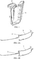
FIG. 1 is a schematic diagram of an overall structure of a rotary active side air curtain assembly according to a preferred embodiment of the present invention; -
FIG. 2A is a schematic diagram of the rotary active side air curtain assembly ofFIG. 1 in an open state; -
FIG. 2B is a schematic diagram of the rotary active side air curtain assembly ofFIG. 1 in a closed state; -
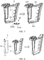
FIG. 3 is a schematic diagram showing the mounting of a baseplate of the rotary active side air curtain assembly ofFIG. 1 ; -
FIG. 4 is a schematic diagram showing the mounting of a rotating element of the rotary active side air curtain assembly ofFIG. 1 ; and -
FIG. 5 is a schematic diagram showing the mounting of a driving mechanism of the rotary active side air curtain assembly ofFIG. 1 . - The following provides preferred embodiments of the present invention with reference to the accompanying drawings and provides detailed descriptions.
- As shown in
FIG. 1 , a rotary active side air curtain assembly according to a preferred embodiment of the present invention includes awind guide element 1, arotating element 2, and adriving mechanism 3. The rotatingelement 2 is mounted on thewind guide element 1. Thedriving mechanism 3 is connected to the rotatingelement 2 to drive the rotatingelement 2 to rotate between an open position and a closed position. In an open state shown inFIG. 2A , the rotatingelement 2 is opened to reduce wind pressure in this area and reduce wind resistance, which corresponds to a vehicle high-speed running state. In a closed state shown inFIG. 2B , the rotatingelement 2 is closed to keep original styling, which corresponds to a vehicle a low-speed state or a vehicle parking state. - As shown in
FIG. 3 , thewind guide element 1 includes atop part 11 and abase part 12 that are fixedly connected and opposite to each other. A structure of thewind guide element 1 is similar to that of a wind guide element in the prior art and thus is not described herein. It is different from the prior art in that amounting base 111 is formed on thetop part 11, and abaseplate 121 is mounted on a top surface of thebase part 12. Specifically, a middle part of thebaseplate 121 is provided with a screw throughhole 121a, and ascrew 13 runs through the screw throughhole 121a to fasten thebaseplate 121 to thebase part 12. In addition, a corner of thebaseplate 121 is provided with amounting hole 121b. It should be understood that, thebaseplate 121 is a wear-resistant plate. - As shown in
FIG. 4 , therotating element 2 is disposed between thetop part 11 and thebase part 12 of thewind guide element 1. Specifically, therotating element 2 includes a rotatingshaft 21. A top end of the rotatingshaft 21 pivotably runs through thetop part 11 and extends upward. A bottom end of the rotatingshaft 21 is inserted into themounting hole 121b of the baseplate 121 (refer toFIG. 3 ) to pivot. The rotatingelement 2 further includes ablade 22 connected to the rotatingshaft 21 and theblade 22 is driven to rotate by rotation of the rotatingshaft 21. As shown inFIG. 2A , when the rotatingshaft 21 is rotated to drive theblade 22 to rotate to the open position, theblade 22 does not cover an air outlet, the wind pressure in this area is thus reduced. It should be understood that, the extent to which the air outlet is opened (i.e. the extent to which theblade 22 covers the air outlet) may be adjusted according to the driving speed of the vehicle. As shown inFIG. 2B , when the rotatingshaft 21 is rotated to drive theblade 22 to rotate to the closed position, theblade 22 covers the air outlet completely, the original styling of the vehicle is thus restored and the appearance of the vehicle in low-speed or parking state is improved. It should be understood that, a specific shape of theblade 22 is not limited, and may be designed according to different shapes of the air outlet. - As shown in
FIG. 5 , thedriving mechanism 3 is an electrical motor which is mounted in themounting base 111 of thetop part 11 of thewind guide element 1 and is connected to the top end of the rotatingshaft 21 to drive the rotatingshaft 21 to rotate. - In addition, the driving mechanism is connected to a body control module (BCM) or an electronic control unit (ECU) of a vehicle. In this way, the BCM or ECU may send an instruction according to a speed of the entire vehicle to accurately control the opening of the
blade 22 through thedriving mechanism 3 and therotating shaft 21. Wind pressure in an area of the rotary active side air curtain is improved through the opening and closing of theblade 22, thus wind resistance of the entire vehicle is improved and the perfection of the entire vehicle styling is ensured. - The foregoing descriptions are merely preferred embodiments of the present invention, but are not intended to limit the scope of the present invention. Various changes may be further made to the foregoing embodiments of the present invention. That is, a simple, equivalent change and modification made according to the claims of this application and the content of the specification of the present invention shall fall within the protection scope of the present invention. What is not described in detail in the present invention all belongs to common technologies.
Claims (9)
- A rotary active side air curtain assembly for a motor vehicle, characterized in that the rotary active side air curtain assembly comprises a wind guide element (1), a rotating element (2), and a driving mechanism (3), wherein the rotating element (2) comprises a rotating shaft (21) and a blade (22) that are fixed to one another, the blade (22) being mounted on the wind guide element (1) through the rotating shaft (21), and wherein the driving mechanism (3) is connected to the rotating shaft and can drive the rotating shaft to rotate so as to drive the blade (22) to rotate between an open position and a closed position.
- The rotary active side air curtain assembly for a motor vehicle according to claim 1, wherein the wind guide element (1) is provided with a top part (11) and a base part (12) that are opposite to each other, and the rotating shaft (21) is pivotably mounted between the top part (11) and the base part (12).
- The rotary active side air curtain assembly for a motor vehicle according to claim 2, wherein the base part (12) is mounted with a baseplate (121) which is provided with a mounting hole (121b), and a bottom end of the rotating shaft (21) is pivotably inserted into the mounting hole (121b) .
- The rotary active side air curtain assembly for a motor vehicle according to claim 3, wherein the baseplate (121) is a wear-resistant plate.
- The rotary active side air curtain assembly for a motor vehicle according to claim 3 or 4, wherein a middle part of the baseplate (121) is provided with a screw through hole (121a), and a screw (13) runs through the screw through hole (121a) to fasten the baseplate (121) to the base part (12).
- The rotary active side air curtain assembly for a motor vehicle according to anyone of claims 2 to 5, wherein the top part (11) is provided with a mounting base (111) in which the driving mechanism (3) is mounted, and a top end of the rotating shaft (21) pivotably runs through the top part (11) and extends upward and is connected to the driving mechanism (3).
- The rotary active side air curtain assembly for a motor vehicle according to anyone of preceding claims, wherein the driving mechanism (3) is connected to a body control module or an electronic control unit of a vehicle.
- The rotary active side air curtain assembly for a motor vehicle according to anyone of preceding claims, wherein the driving mechanism (3) is an electrical motor.
- A motor vehicle comprising a rotary active side air curtain assembly according to anyone of preceding claims.
Applications Claiming Priority (2)
| Application Number | Priority Date | Filing Date | Title |
|---|---|---|---|
| CN201910854139.5A CN110510010A (en) | 2019-09-10 | 2019-09-10 | A kind of rotary active side curtain airbag assembly |
| CN201921501170.2U CN210437281U (en) | 2019-09-10 | 2019-09-10 | A rotary active side air curtain assembly |
Publications (2)
| Publication Number | Publication Date |
|---|---|
| EP3792158A1 true EP3792158A1 (en) | 2021-03-17 |
| EP3792158B1 EP3792158B1 (en) | 2023-08-02 |
Family
ID=68502996
Family Applications (1)
| Application Number | Title | Priority Date | Filing Date |
|---|---|---|---|
| EP19207878.0A Active EP3792158B1 (en) | 2019-09-10 | 2019-11-08 | Rotary active side air curtain assembly for a motor vehicle |
Country Status (1)
| Country | Link |
|---|---|
| EP (1) | EP3792158B1 (en) |
Citations (5)
| Publication number | Priority date | Publication date | Assignee | Title |
|---|---|---|---|---|
| DE102008019923A1 (en) * | 2008-04-21 | 2009-10-22 | Bayerische Motoren Werke Aktiengesellschaft | Motor vehicle has front wheel housing and flow channel that is formed in base plate at rear range of respective wheel housing, at which front end of side door sill is attached |
| US20160016617A1 (en) * | 2014-07-21 | 2016-01-21 | Dr. Ing. H.C. F. Porsche Aktiengesellschaft | Front of a motor vehicle |
| GB2528927A (en) * | 2014-08-05 | 2016-02-10 | Jaguar Land Rover Ltd | Vehicle aerodynamic apparatus |
| DE102016104359A1 (en) * | 2015-03-17 | 2016-09-22 | GM Global Technology Operations LLC (n. d. Ges. d. Staates Delaware) | VEHICLE WITH INTEGRATED AIR CURTAIN AND INTEGRATED BRAKE COOLING PIPE |
| US20170361879A1 (en) * | 2016-06-17 | 2017-12-21 | Srg Global Inc. | Vehicle active side vent system |
-
2019
- 2019-11-08 EP EP19207878.0A patent/EP3792158B1/en active Active
Patent Citations (5)
| Publication number | Priority date | Publication date | Assignee | Title |
|---|---|---|---|---|
| DE102008019923A1 (en) * | 2008-04-21 | 2009-10-22 | Bayerische Motoren Werke Aktiengesellschaft | Motor vehicle has front wheel housing and flow channel that is formed in base plate at rear range of respective wheel housing, at which front end of side door sill is attached |
| US20160016617A1 (en) * | 2014-07-21 | 2016-01-21 | Dr. Ing. H.C. F. Porsche Aktiengesellschaft | Front of a motor vehicle |
| GB2528927A (en) * | 2014-08-05 | 2016-02-10 | Jaguar Land Rover Ltd | Vehicle aerodynamic apparatus |
| DE102016104359A1 (en) * | 2015-03-17 | 2016-09-22 | GM Global Technology Operations LLC (n. d. Ges. d. Staates Delaware) | VEHICLE WITH INTEGRATED AIR CURTAIN AND INTEGRATED BRAKE COOLING PIPE |
| US20170361879A1 (en) * | 2016-06-17 | 2017-12-21 | Srg Global Inc. | Vehicle active side vent system |
Also Published As
| Publication number | Publication date |
|---|---|
| EP3792158B1 (en) | 2023-08-02 |
Similar Documents
| Publication | Publication Date | Title |
|---|---|---|
| CN111002797B (en) | Window wind noise and wind vibration adjustment device and vehicle | |
| CN208962867U (en) | Cell structure with air inlet adjustment function | |
| CN108216391B (en) | automobile rear protective lower guard plate structure | |
| KR101631565B1 (en) | Active Air Flap | |
| CN108454384A (en) | A kind of automobile active air inlet grille device | |
| CN208085479U (en) | A kind of automobile active air inlet grille device | |
| EP3792157A1 (en) | Translatable active side air curtain assembly for a motor vehicle | |
| EP3792158B1 (en) | Rotary active side air curtain assembly for a motor vehicle | |
| CN110450866A (en) | A kind of rotary automobile active diffuser | |
| CN210437282U (en) | A mobile active side air curtain assembly | |
| CN210437281U (en) | A rotary active side air curtain assembly | |
| CN110450865A (en) | A kind of movable type active side curtain airbag assembly | |
| KR101423729B1 (en) | Speed sensitive auto lip spoiler | |
| CN212242888U (en) | Front-rear blowing face control mechanism of automobile air conditioner | |
| CN110510010A (en) | A kind of rotary active side curtain airbag assembly | |
| CN221113442U (en) | Electric air outlet mechanism, instrument panel assembly and vehicle | |
| CN115200825B (en) | Method, system, equipment and medium for acquiring automobile model tail test data | |
| CN207345672U (en) | The car side back sight lens device that a kind of preventing water drops are resident | |
| CN223919110U (en) | Air inlet grille and vehicle | |
| CN213619675U (en) | an illuminated grille | |
| CN211369972U (en) | Intelligent opening and closing mechanism for tail box cover | |
| KR20060004185A (en) | Car air vent device | |
| CN218400197U (en) | Can regulate and control car initiative air-inlet grille of drag reduction | |
| CN2813347Y (en) | Vehicle air conditioner air outlet | |
| CN206579456U (en) | Vehicle door and the window regulator system at back door for motor vehicles |
Legal Events
| Date | Code | Title | Description |
|---|---|---|---|
| PUAI | Public reference made under article 153(3) epc to a published international application that has entered the european phase |
Free format text: ORIGINAL CODE: 0009012 |
|
| STAA | Information on the status of an ep patent application or granted ep patent |
Free format text: STATUS: THE APPLICATION HAS BEEN PUBLISHED |
|
| AK | Designated contracting states |
Kind code of ref document: A1 Designated state(s): AL AT BE BG CH CY CZ DE DK EE ES FI FR GB GR HR HU IE IS IT LI LT LU LV MC MK MT NL NO PL PT RO RS SE SI SK SM TR |
|
| AX | Request for extension of the european patent |
Extension state: BA ME |
|
| STAA | Information on the status of an ep patent application or granted ep patent |
Free format text: STATUS: REQUEST FOR EXAMINATION WAS MADE |
|
| 17P | Request for examination filed |
Effective date: 20210910 |
|
| RBV | Designated contracting states (corrected) |
Designated state(s): AL AT BE BG CH CY CZ DE DK EE ES FI FR GB GR HR HU IE IS IT LI LT LU LV MC MK MT NL NO PL PT RO RS SE SI SK SM TR |
|
| GRAP | Despatch of communication of intention to grant a patent |
Free format text: ORIGINAL CODE: EPIDOSNIGR1 |
|
| STAA | Information on the status of an ep patent application or granted ep patent |
Free format text: STATUS: GRANT OF PATENT IS INTENDED |
|
| INTG | Intention to grant announced |
Effective date: 20230306 |
|
| GRAS | Grant fee paid |
Free format text: ORIGINAL CODE: EPIDOSNIGR3 |
|
| GRAA | (expected) grant |
Free format text: ORIGINAL CODE: 0009210 |
|
| STAA | Information on the status of an ep patent application or granted ep patent |
Free format text: STATUS: THE PATENT HAS BEEN GRANTED |
|
| P01 | Opt-out of the competence of the unified patent court (upc) registered |
Effective date: 20230525 |
|
| AK | Designated contracting states |
Kind code of ref document: B1 Designated state(s): AL AT BE BG CH CY CZ DE DK EE ES FI FR GB GR HR HU IE IS IT LI LT LU LV MC MK MT NL NO PL PT RO RS SE SI SK SM TR |
|
| REG | Reference to a national code |
Ref country code: GB Ref legal event code: FG4D |
|
| REG | Reference to a national code |
Ref country code: CH Ref legal event code: EP |
|
| REG | Reference to a national code |
Ref country code: DE Ref legal event code: R096 Ref document number: 602019033934 Country of ref document: DE |
|
| REG | Reference to a national code |
Ref country code: IE Ref legal event code: FG4D |
|
| REG | Reference to a national code |
Ref country code: LT Ref legal event code: MG9D |
|
| REG | Reference to a national code |
Ref country code: NL Ref legal event code: MP Effective date: 20230802 |
|
| REG | Reference to a national code |
Ref country code: AT Ref legal event code: MK05 Ref document number: 1594407 Country of ref document: AT Kind code of ref document: T Effective date: 20230802 |
|
| PG25 | Lapsed in a contracting state [announced via postgrant information from national office to epo] |
Ref country code: GR Free format text: LAPSE BECAUSE OF FAILURE TO SUBMIT A TRANSLATION OF THE DESCRIPTION OR TO PAY THE FEE WITHIN THE PRESCRIBED TIME-LIMIT Effective date: 20231103 |
|
| PG25 | Lapsed in a contracting state [announced via postgrant information from national office to epo] |
Ref country code: IS Free format text: LAPSE BECAUSE OF FAILURE TO SUBMIT A TRANSLATION OF THE DESCRIPTION OR TO PAY THE FEE WITHIN THE PRESCRIBED TIME-LIMIT Effective date: 20231202 |
|
| PG25 | Lapsed in a contracting state [announced via postgrant information from national office to epo] |
Ref country code: SE Free format text: LAPSE BECAUSE OF FAILURE TO SUBMIT A TRANSLATION OF THE DESCRIPTION OR TO PAY THE FEE WITHIN THE PRESCRIBED TIME-LIMIT Effective date: 20230802 Ref country code: RS Free format text: LAPSE BECAUSE OF FAILURE TO SUBMIT A TRANSLATION OF THE DESCRIPTION OR TO PAY THE FEE WITHIN THE PRESCRIBED TIME-LIMIT Effective date: 20230802 Ref country code: PT Free format text: LAPSE BECAUSE OF FAILURE TO SUBMIT A TRANSLATION OF THE DESCRIPTION OR TO PAY THE FEE WITHIN THE PRESCRIBED TIME-LIMIT Effective date: 20231204 Ref country code: NO Free format text: LAPSE BECAUSE OF FAILURE TO SUBMIT A TRANSLATION OF THE DESCRIPTION OR TO PAY THE FEE WITHIN THE PRESCRIBED TIME-LIMIT Effective date: 20231102 Ref country code: NL Free format text: LAPSE BECAUSE OF FAILURE TO SUBMIT A TRANSLATION OF THE DESCRIPTION OR TO PAY THE FEE WITHIN THE PRESCRIBED TIME-LIMIT Effective date: 20230802 Ref country code: LV Free format text: LAPSE BECAUSE OF FAILURE TO SUBMIT A TRANSLATION OF THE DESCRIPTION OR TO PAY THE FEE WITHIN THE PRESCRIBED TIME-LIMIT Effective date: 20230802 Ref country code: LT Free format text: LAPSE BECAUSE OF FAILURE TO SUBMIT A TRANSLATION OF THE DESCRIPTION OR TO PAY THE FEE WITHIN THE PRESCRIBED TIME-LIMIT Effective date: 20230802 Ref country code: IS Free format text: LAPSE BECAUSE OF FAILURE TO SUBMIT A TRANSLATION OF THE DESCRIPTION OR TO PAY THE FEE WITHIN THE PRESCRIBED TIME-LIMIT Effective date: 20231202 Ref country code: HR Free format text: LAPSE BECAUSE OF FAILURE TO SUBMIT A TRANSLATION OF THE DESCRIPTION OR TO PAY THE FEE WITHIN THE PRESCRIBED TIME-LIMIT Effective date: 20230802 Ref country code: GR Free format text: LAPSE BECAUSE OF FAILURE TO SUBMIT A TRANSLATION OF THE DESCRIPTION OR TO PAY THE FEE WITHIN THE PRESCRIBED TIME-LIMIT Effective date: 20231103 Ref country code: FI Free format text: LAPSE BECAUSE OF FAILURE TO SUBMIT A TRANSLATION OF THE DESCRIPTION OR TO PAY THE FEE WITHIN THE PRESCRIBED TIME-LIMIT Effective date: 20230802 Ref country code: AT Free format text: LAPSE BECAUSE OF FAILURE TO SUBMIT A TRANSLATION OF THE DESCRIPTION OR TO PAY THE FEE WITHIN THE PRESCRIBED TIME-LIMIT Effective date: 20230802 |
|
| PG25 | Lapsed in a contracting state [announced via postgrant information from national office to epo] |
Ref country code: PL Free format text: LAPSE BECAUSE OF FAILURE TO SUBMIT A TRANSLATION OF THE DESCRIPTION OR TO PAY THE FEE WITHIN THE PRESCRIBED TIME-LIMIT Effective date: 20230802 |
|
| PG25 | Lapsed in a contracting state [announced via postgrant information from national office to epo] |
Ref country code: ES Free format text: LAPSE BECAUSE OF FAILURE TO SUBMIT A TRANSLATION OF THE DESCRIPTION OR TO PAY THE FEE WITHIN THE PRESCRIBED TIME-LIMIT Effective date: 20230802 |
|
| PG25 | Lapsed in a contracting state [announced via postgrant information from national office to epo] |
Ref country code: SM Free format text: LAPSE BECAUSE OF FAILURE TO SUBMIT A TRANSLATION OF THE DESCRIPTION OR TO PAY THE FEE WITHIN THE PRESCRIBED TIME-LIMIT Effective date: 20230802 Ref country code: RO Free format text: LAPSE BECAUSE OF FAILURE TO SUBMIT A TRANSLATION OF THE DESCRIPTION OR TO PAY THE FEE WITHIN THE PRESCRIBED TIME-LIMIT Effective date: 20230802 Ref country code: ES Free format text: LAPSE BECAUSE OF FAILURE TO SUBMIT A TRANSLATION OF THE DESCRIPTION OR TO PAY THE FEE WITHIN THE PRESCRIBED TIME-LIMIT Effective date: 20230802 Ref country code: EE Free format text: LAPSE BECAUSE OF FAILURE TO SUBMIT A TRANSLATION OF THE DESCRIPTION OR TO PAY THE FEE WITHIN THE PRESCRIBED TIME-LIMIT Effective date: 20230802 Ref country code: DK Free format text: LAPSE BECAUSE OF FAILURE TO SUBMIT A TRANSLATION OF THE DESCRIPTION OR TO PAY THE FEE WITHIN THE PRESCRIBED TIME-LIMIT Effective date: 20230802 Ref country code: CZ Free format text: LAPSE BECAUSE OF FAILURE TO SUBMIT A TRANSLATION OF THE DESCRIPTION OR TO PAY THE FEE WITHIN THE PRESCRIBED TIME-LIMIT Effective date: 20230802 Ref country code: SK Free format text: LAPSE BECAUSE OF FAILURE TO SUBMIT A TRANSLATION OF THE DESCRIPTION OR TO PAY THE FEE WITHIN THE PRESCRIBED TIME-LIMIT Effective date: 20230802 |
|
| REG | Reference to a national code |
Ref country code: DE Ref legal event code: R097 Ref document number: 602019033934 Country of ref document: DE |
|
| PG25 | Lapsed in a contracting state [announced via postgrant information from national office to epo] |
Ref country code: IT Free format text: LAPSE BECAUSE OF FAILURE TO SUBMIT A TRANSLATION OF THE DESCRIPTION OR TO PAY THE FEE WITHIN THE PRESCRIBED TIME-LIMIT Effective date: 20230802 |
|
| REG | Reference to a national code |
Ref country code: DE Ref legal event code: R119 Ref document number: 602019033934 Country of ref document: DE |
|
| PLBE | No opposition filed within time limit |
Free format text: ORIGINAL CODE: 0009261 |
|
| STAA | Information on the status of an ep patent application or granted ep patent |
Free format text: STATUS: NO OPPOSITION FILED WITHIN TIME LIMIT |
|
| REG | Reference to a national code |
Ref country code: CH Ref legal event code: PL |
|
| PG25 | Lapsed in a contracting state [announced via postgrant information from national office to epo] |
Ref country code: MC Free format text: LAPSE BECAUSE OF FAILURE TO SUBMIT A TRANSLATION OF THE DESCRIPTION OR TO PAY THE FEE WITHIN THE PRESCRIBED TIME-LIMIT Effective date: 20230802 |
|
| 26N | No opposition filed |
Effective date: 20240503 |
|
| PG25 | Lapsed in a contracting state [announced via postgrant information from national office to epo] |
Ref country code: LU Free format text: LAPSE BECAUSE OF NON-PAYMENT OF DUE FEES Effective date: 20231108 |
|
| PG25 | Lapsed in a contracting state [announced via postgrant information from national office to epo] |
Ref country code: CH Free format text: LAPSE BECAUSE OF NON-PAYMENT OF DUE FEES Effective date: 20231130 |
|
| GBPC | Gb: european patent ceased through non-payment of renewal fee |
Effective date: 20231108 |
|
| PG25 | Lapsed in a contracting state [announced via postgrant information from national office to epo] |
Ref country code: MC Free format text: LAPSE BECAUSE OF FAILURE TO SUBMIT A TRANSLATION OF THE DESCRIPTION OR TO PAY THE FEE WITHIN THE PRESCRIBED TIME-LIMIT Effective date: 20230802 Ref country code: LU Free format text: LAPSE BECAUSE OF NON-PAYMENT OF DUE FEES Effective date: 20231108 Ref country code: CH Free format text: LAPSE BECAUSE OF NON-PAYMENT OF DUE FEES Effective date: 20231130 Ref country code: SI Free format text: LAPSE BECAUSE OF FAILURE TO SUBMIT A TRANSLATION OF THE DESCRIPTION OR TO PAY THE FEE WITHIN THE PRESCRIBED TIME-LIMIT Effective date: 20230802 |
|
| REG | Reference to a national code |
Ref country code: BE Ref legal event code: MM Effective date: 20231130 |
|
| REG | Reference to a national code |
Ref country code: IE Ref legal event code: MM4A |
|
| PG25 | Lapsed in a contracting state [announced via postgrant information from national office to epo] |
Ref country code: IE Free format text: LAPSE BECAUSE OF NON-PAYMENT OF DUE FEES Effective date: 20231108 Ref country code: DE Free format text: LAPSE BECAUSE OF NON-PAYMENT OF DUE FEES Effective date: 20240601 |
|
| PG25 | Lapsed in a contracting state [announced via postgrant information from national office to epo] |
Ref country code: GB Free format text: LAPSE BECAUSE OF NON-PAYMENT OF DUE FEES Effective date: 20231108 |
|
| PG25 | Lapsed in a contracting state [announced via postgrant information from national office to epo] |
Ref country code: BE Free format text: LAPSE BECAUSE OF NON-PAYMENT OF DUE FEES Effective date: 20231130 |
|
| PG25 | Lapsed in a contracting state [announced via postgrant information from national office to epo] |
Ref country code: FR Free format text: LAPSE BECAUSE OF NON-PAYMENT OF DUE FEES Effective date: 20231130 |
|
| PG25 | Lapsed in a contracting state [announced via postgrant information from national office to epo] |
Ref country code: IE Free format text: LAPSE BECAUSE OF NON-PAYMENT OF DUE FEES Effective date: 20231108 Ref country code: GB Free format text: LAPSE BECAUSE OF NON-PAYMENT OF DUE FEES Effective date: 20231108 Ref country code: FR Free format text: LAPSE BECAUSE OF NON-PAYMENT OF DUE FEES Effective date: 20231130 Ref country code: DE Free format text: LAPSE BECAUSE OF NON-PAYMENT OF DUE FEES Effective date: 20240601 Ref country code: BE Free format text: LAPSE BECAUSE OF NON-PAYMENT OF DUE FEES Effective date: 20231130 |
|
| PG25 | Lapsed in a contracting state [announced via postgrant information from national office to epo] |
Ref country code: BG Free format text: LAPSE BECAUSE OF FAILURE TO SUBMIT A TRANSLATION OF THE DESCRIPTION OR TO PAY THE FEE WITHIN THE PRESCRIBED TIME-LIMIT Effective date: 20230802 |
|
| PG25 | Lapsed in a contracting state [announced via postgrant information from national office to epo] |
Ref country code: BG Free format text: LAPSE BECAUSE OF FAILURE TO SUBMIT A TRANSLATION OF THE DESCRIPTION OR TO PAY THE FEE WITHIN THE PRESCRIBED TIME-LIMIT Effective date: 20230802 |
|
| PG25 | Lapsed in a contracting state [announced via postgrant information from national office to epo] |
Ref country code: CY Free format text: LAPSE BECAUSE OF FAILURE TO SUBMIT A TRANSLATION OF THE DESCRIPTION OR TO PAY THE FEE WITHIN THE PRESCRIBED TIME-LIMIT; INVALID AB INITIO Effective date: 20191108 |
|
| PG25 | Lapsed in a contracting state [announced via postgrant information from national office to epo] |
Ref country code: HU Free format text: LAPSE BECAUSE OF FAILURE TO SUBMIT A TRANSLATION OF THE DESCRIPTION OR TO PAY THE FEE WITHIN THE PRESCRIBED TIME-LIMIT; INVALID AB INITIO Effective date: 20191108 |
|
| PG25 | Lapsed in a contracting state [announced via postgrant information from national office to epo] |
Ref country code: TR Free format text: LAPSE BECAUSE OF FAILURE TO SUBMIT A TRANSLATION OF THE DESCRIPTION OR TO PAY THE FEE WITHIN THE PRESCRIBED TIME-LIMIT Effective date: 20230802 |