EP3791991A1 - Friction joining device and method for operating same - Google Patents
Friction joining device and method for operating same Download PDFInfo
- Publication number
- EP3791991A1 EP3791991A1 EP19799780.2A EP19799780A EP3791991A1 EP 3791991 A1 EP3791991 A1 EP 3791991A1 EP 19799780 A EP19799780 A EP 19799780A EP 3791991 A1 EP3791991 A1 EP 3791991A1
- Authority
- EP
- European Patent Office
- Prior art keywords
- tool
- joined object
- friction welding
- axis
- welding apparatus
- Prior art date
- Legal status (The legal status is an assumption and is not a legal conclusion. Google has not performed a legal analysis and makes no representation as to the accuracy of the status listed.)
- Withdrawn
Links
Images




Classifications
-
- B—PERFORMING OPERATIONS; TRANSPORTING
- B23—MACHINE TOOLS; METAL-WORKING NOT OTHERWISE PROVIDED FOR
- B23K—SOLDERING OR UNSOLDERING; WELDING; CLADDING OR PLATING BY SOLDERING OR WELDING; CUTTING BY APPLYING HEAT LOCALLY, e.g. FLAME CUTTING; WORKING BY LASER BEAM
- B23K20/00—Non-electric welding by applying impact or other pressure, with or without the application of heat, e.g. cladding or plating
- B23K20/12—Non-electric welding by applying impact or other pressure, with or without the application of heat, e.g. cladding or plating the heat being generated by friction; Friction welding
- B23K20/121—Control circuits therefor
-
- B—PERFORMING OPERATIONS; TRANSPORTING
- B23—MACHINE TOOLS; METAL-WORKING NOT OTHERWISE PROVIDED FOR
- B23K—SOLDERING OR UNSOLDERING; WELDING; CLADDING OR PLATING BY SOLDERING OR WELDING; CUTTING BY APPLYING HEAT LOCALLY, e.g. FLAME CUTTING; WORKING BY LASER BEAM
- B23K20/00—Non-electric welding by applying impact or other pressure, with or without the application of heat, e.g. cladding or plating
- B23K20/12—Non-electric welding by applying impact or other pressure, with or without the application of heat, e.g. cladding or plating the heat being generated by friction; Friction welding
- B23K20/122—Non-electric welding by applying impact or other pressure, with or without the application of heat, e.g. cladding or plating the heat being generated by friction; Friction welding using a non-consumable tool, e.g. friction stir welding
- B23K20/1265—Non-butt welded joints, e.g. overlap-joints, T-joints or spot welds
-
- B—PERFORMING OPERATIONS; TRANSPORTING
- B23—MACHINE TOOLS; METAL-WORKING NOT OTHERWISE PROVIDED FOR
- B23K—SOLDERING OR UNSOLDERING; WELDING; CLADDING OR PLATING BY SOLDERING OR WELDING; CUTTING BY APPLYING HEAT LOCALLY, e.g. FLAME CUTTING; WORKING BY LASER BEAM
- B23K20/00—Non-electric welding by applying impact or other pressure, with or without the application of heat, e.g. cladding or plating
- B23K20/12—Non-electric welding by applying impact or other pressure, with or without the application of heat, e.g. cladding or plating the heat being generated by friction; Friction welding
- B23K20/122—Non-electric welding by applying impact or other pressure, with or without the application of heat, e.g. cladding or plating the heat being generated by friction; Friction welding using a non-consumable tool, e.g. friction stir welding
- B23K20/1245—Non-electric welding by applying impact or other pressure, with or without the application of heat, e.g. cladding or plating the heat being generated by friction; Friction welding using a non-consumable tool, e.g. friction stir welding characterised by the apparatus
- B23K20/125—Rotary tool drive mechanism
Definitions
- the present disclosure relates to a friction welding apparatus and a method of operating the same.
- a method of joining dissimilar metal plates is known in which a first metal plate is piled up with a second metal plate made of material of which a melting point is higher than the first metal plate, and these metal plates are joined to each other using frictional heat (e.g., see Patent Document 1).
- a pin having a curved surface is provided.
- softened metal parts which are pushed away along the curved surface of the pin continue integrally, and at the boundary of both the softened metal parts, the softened metal part of the second metal plate covers the softened metal part of the first metal plate to serve as an anchoring structure, thereby joining the first metal plate and the second metal plate.
- the electrodeposition coating in order to prevent the corrosion of the metal, it is possible to apply the electrodeposition coating.
- the joined part is immersed in a coating fluid pan while an opening of the recess formed in the joined part is turned downwardly, air is caught in the recess to impede the coating fluid from entering into the recess, and therefore, the coating may become inadequate.
- the present disclosure is made in view of solving the problem, and one purpose thereof is to provide a friction welding apparatus and a method of operating the same, capable of realizing an appropriate corrosion resistance, even if a plurality of members made of different materials are joined by a friction welding method.
- a friction welding apparatus configured to join a to-be-joined object having a first member and a second member by softening the to-be-joined object with frictional heat.
- the apparatus includes a tool formed cylindrically, and rotatable about an axis thereof and reciprocatable in a direction along the axis, a rotary driver configured to rotate the tool about the axis, a linear driver configured to reciprocate the tool along the axis, and a control device.
- the first member is disposed opposing to the tool and is made of a different type of material from the second member.
- the control device (A) controls the linear driver and the rotary driver so that the tool is rotated about the axis while a tip-end part of the tool is pressed against the to-be-joined object to form a through-hole in the to-be-joined object so that the softened second member sticks into the softened first member to join the to-be-joined object.
- the electrodeposition coating unlike a recess, air inside the through-hole can be taken out by coating fluid and, thus, the coating fluid can sufficiently be taken into the through-hole so as to coat inside the through-hole. Therefore, it can reduce corrosion of one of metals with a larger ionization tendency at the joining interface of the to-be-joined object.
- a friction welding apparatus configured to join a to-be-joined object having a first member and a second member by softening the to-be-joined object with frictional heat.
- the friction welding apparatus includes a tool formed cylindrically, and rotatable about an axis thereof and reciprocatable in a direction along the axis, a rotary driver configured to rotate the tool about the axis, a linear driver configured to reciprocate the tool along the axis, a cutting tool, a first driver configured to drive the cutting tool, and a control device.
- the first member is disposed opposing to the tool and is made of a different type of material from the second member.
- the control device (B) controls the linear driver and the rotary driver so that the tool is rotated about the axis while a tip-end part of the tool is pressed against the to-be-joined object to form a recess in the to-be-joined object so that the softened second member sticks into the softened first member to join the to-be-joined object, and then (C) controls the first driver so that a through-hole is formed in the recess by the cutting tool.
- the through-hole is formed in the recess, even if water exists inside the recess of the to-be-joined object, the water is discharged from the through-hole.
- it can reduce corrosion of one of metals with a larger ionization tendency at the joining interface of the to-be-joined object.
- a method of operating a friction welding apparatus is a method of operating a friction welding apparatus configured to join a to-be-joined object having a first member and a second member by softening the to-be-joined object with frictional heat.
- the friction welding apparatus includes a tool formed cylindrically, and rotatable about an axis thereof and reciprocatable in a direction along the axis, a rotary driver configured to rotate the tool about the axis, and a linear driver configured to reciprocate the tool along the axis.
- the first member is disposed opposing to the tool and is made of a different type of material from the second member.
- the method includes the step of (A) operating the linear driver and the rotary driver so that the tool is rotated about the axis while a tip-end part of the tool is pressed against the to-be-joined object to form a through-hole in the to-be-joined object so that the softened second member sticks into the softened first member to join the to-be-joined object.
- the electrodeposition coating unlike a recess, air inside the through-hole can be taken out by coating fluid and, thus, the coating fluid can sufficiently be taken into the through-hole so as to coat inside the through-hole. Therefore, it can reduce corrosion of one of metals with a larger ionization tendency at the joining interface of the to-be-joined object.
- a method of operating a friction welding apparatus is a method of operating a friction welding apparatus configured to join a to-be-joined object having a first member and a second member by softening the to-be-joined object with frictional heat.
- the friction welding apparatus includes a tool formed cylindrically, and rotatable about an axis thereof and reciprocatable in a direction along the axis, a rotary driver configured to rotate the tool about the axis, a linear driver configured to reciprocate the tool along the axis, a cutting tool, and a first driver configured to drive the cutting tool.
- the first member is disposed opposing to the tool and is made of a different type of material from the second member.
- the method includes the steps of (B) operating the linear driver and the rotary driver so that the tool is rotated about the axis while a tip-end part of the tool is pressed against the to-be-joined object to form a recess in the to-be-joined object so that the softened second member sticks into the softened first member to join the to-be-joined object, and (C) then operating the first driver so that a through-hole is formed in the recess by the cutting tool.
- the through-hole is formed in the recess, even if water exists inside the through-hole of the to-be-joined object, the water is discharged from the through-hole.
- it can reduce corrosion of one of metals with a larger ionization tendency at the joining interface of the to-be-joined object.
- an appropriate corrosion resistance can be achieved even if a plurality of members made of different materials are joined by a friction welding method.
- a friction welding apparatus is a friction welding apparatus which joins a to-be-joined object having a first member and a second member by softening the to-be-joined object with frictional heat.
- the apparatus includes a tool which is formed cylindrically, and is rotatable about its axis and reciprocatable in a direction along the axis, a rotary driver which rotates the tool about the axis, a linear driver which reciprocates the tool along the axis, and a control device.
- the first member is disposed opposing to the tool and is made of a different type of material from the second member.
- the control device (A) controls the linear driver and the rotary driver so that the tool is rotated about the axis while a tip-end part of the tool is pressed against the to-be-joined object to form a through-hole in the to-be-joined object so that the softened second member sticks into the softened first member to join the to-be-joined object.
- control device may control the linear driver and the rotary driver, during (A), so that the tip-end part of the tool penetrates the second member of the to-be-joined object.
- Fig. 1 is a schematic view illustrating an outline structure of the friction welding apparatus according to Embodiment 1.
- a friction welding apparatus 1 includes a tool 10, a base body 2, a movable body 3, a tool holder 4, a linear driver 7, a rotary driver 8, and a control device 30.
- the apparatus softens with frictional heat and agitates (stirs) a point joining part Wa of a to-be-joined object W to cause a plastic flow of the point joining part Wa to perform a friction welding.
- the base body 2 is detachably attached to a tip-end part of a robotic arm 9.
- the movable body 3 is attached to the base body 2 movably in a direction of an axis X of the tool holder 4.
- the tool holder 4 is provided to a tip-end part of the movable body 3.
- the tool holder 4 is rotatable about its axis X, and is movable in the direction of the axis X integrally with the movable body 3.
- the tool 10 is detachably provided to a tip-end part of the tool holder 4. Note that the attachment and detachment (replacement) of the tool 10 may be performed by an operator, or may be performed by a robotic arm different from the robotic arm 9.
- the linear driver 7 is disposed inside the base body 2.
- the linear driver 7 moves the movable body 3 (tool 10) linearly in the direction of the axis X.
- the linear driver 7 may be an electric motor (servomotor).
- the rotary driver 8 is disposed inside the movable body 3.
- the rotary driver 8 rotates the tool holder 4 and the tool 10 about the axis X.
- the rotary driver 8 may be an electric motor (servomotor).
- a curved frame 5 formed in a substantially C-shape (a substantially L-shape) is fixed to the base body 2.
- the curved frame 5 is formed so that its tip-end part opposes to the tool 10.
- a support 6 is provided to a tip-end part of the curved frame 5.
- the support 6 supports the to-be-joined object W. That is, in Embodiment 1, the base body 2, the movable body 3, the tool holder 4, the curved frame 5, and the support 6 are comprised of a C-shaped gun (C-shaped frame).
- the to-be-joined object W is comprised of a plate-like first member W1 and a plate-like second member W2.
- the first member W1 may be made of metal (e.g., aluminum) or fiber-reinforced plastic (e.g., carbon fiber reinforced plastic), and the second member W2 may be made of a different metal (e.g., steel) from the first member W1.
- the to-be-joined object W is comprised of the two kinds of members (the first member W1 and the second member W2), it may, but not limited to, be comprised of three or more kinds of members.
- the to-be-joined object W is comprised of the plate-like first member W1 and the plate-like second member W2
- the shape of the to-be-joined object W may be arbitrary, and, for example, it may be, but not limited to, a rectangular parallelepiped shape or may be an arc shape.
- the control device 30 includes a processor, such as a microprocessor and a CPU, and a memory, such as a ROM and a RAM (none of them is illustrated).
- the memory stores information on a basic program, various fixed data, etc.
- the processor controls various operations of the linear driver 7, the rotary driver 8, and the robotic arm 9 by reading and executing software, such as the basic program stored in the memory.
- control device 30 may be comprised of a sole control device 30 which carries out a centralized control, or may be comprised of a plurality of control devices 30 which collaboratively carry out a distributed control.
- control device 30 may be comprised of a microcomputer or may be comprised of a MPU, a PLC (Programmable Logic Controller), a logic circuit, etc.
- Fig. 2 is a flowchart illustrating one example of operation of the friction welding apparatus according to Embodiment 1.
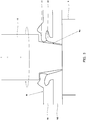
- Fig. 3 is a schematic view illustrating a substantial part of the friction welding apparatus according to Embodiment 1, and illustrates a state where the tool performs a friction welding.
- the operator places the to-be-joined object W on an upper surface of the support 6. Then, the operator operates an input device (not illustrated) to input a joining execution of the to-be-joined object W into the control device 30.
- the control device 30 drives the rotary driver 8 to rotate the tool holder 4 and the tool 10 at a given rotational speed (e.g., 50 to 6,000rpm) (Step S101).
- a given rotational speed e.g. 50 to 6,000rpm
- the control device 30 drives the linear driver 7 to bring the tip-end part of the tool 10 into contact with the point joining part Wa of the to-be-joined object W (Step S102).
- control device 30 controls the linear driver 7 so that the tool 10 is pressed against the to-be-joined object W by a given pressing force set beforehand (e.g., 4kN to 70kN).
- a given pressing force set beforehand e.g., 4kN to 70kN.
- the given rotational speed and the given pressing force may be suitably set beforehand by an experiment etc.
- the point joining part Wa on the first member W1 and the second member W2 is softened by the tip-end part of the tool 10, and a plastic flow of the to-be-joined object W is caused. Moreover, a second part 42 which is the softened part of the second member W2 enters into a first part 41 which is the softened part of the first member W1 to form an anchoring structure.
- the control device 30 drives the linear driver 7 so that the tip end of the tool 10 reaches a contact surface of the support 6 for the to-be-joined object W (Step S103). Then, when the tip end of the tool 10 reaches the contact surface of the support 6 for the to-be-joined object W, the control device 30 drives the linear driver 7 so that the tip-end part of the tool 10 separates from the to-be-joined object W (Step S104). Next, the control device 30 stops the rotary driver 8 (Step S 105), and ends this program.
- a through-hole 40 is formed in the point joining part Wa of the to-be-joined object W. Moreover, the first part 41 which is pushed away by the tip-end part of the tool 10 moves to an opening of the through-hole 40 of the first member W1.
- control device 30 may move the friction welding apparatus 1 above the next point joining part Wa without stopping the rotary driver 8, and perform the operation at Step S 102.
- the anchoring effect is acquired by performing the friction welding to the to-be-joined object W in which the second part 42 which is the softened part of the second member W2 enters into the first part 41 which is the softened part of the first member W1 to increase a tensile-shear strength, and also to increase a peel strength relatively.
- control device 30 controls the linear driver 7 so that the tip end of the tool 10 reaches the contact surface of the support 6 for the to-be-joined object W
- the control device 30 may control the linear driver 7 so that the tip end of the tool 10 may penetrate the contact surface of the support 6 for the to-be-joined object W.
- a recess may be formed for the tip-end part of the tool 10 advancing to the contact surface (upper surface) of the support 6 with the to-be-joined object W.
- a friction welding apparatus is the friction welding apparatus according to Embodiment 1 in which the control device controls the linear driver and the rotary driver, during (A), so that (A1) the tool is rotated about the axis while the tip-end part of the tool is pressed against the to-be-joined object to form a recess in the to-be-joined object so that the softened second member sticks in the softened first member to join the to-be-joined object, and (A2) the tip-end part of the tool reaches a given first position set beforehand to form the through-hole in the to-be-joined object.
- the first position may be 0.2mm or less from a surface of the second member which is opposite from a surface which contacts the first member.
- control device may control the linear driver and the rotary driver, during (A2), so that the tip-end part of the tool reaches the given first position set beforehand to adhere the softened second member in the bottom of the recess to the tip-end part of the tool, and the tool then separates from the to-be-joined object to form the through-hole in the to-be-joined object.
- the first position may be 0.1mm or less from the surface of the second member which is opposite from the surface which contacts the first member.
- the linear driver and the rotary driver are controlled, during (A2), so that the tip-end part of the tool reaches the given first position set beforehand, and the softened second member in the bottom of the recess is pushed away by the tip-end part of the tool to form the through-hole in the to-be-joined object.
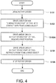
- Fig. 4 is a flowchart illustrating one example of operation of the friction welding apparatus according to Embodiment 2.
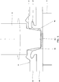
- Fig. 5 is a schematic view illustrating a substantial part of the friction welding apparatus according to Embodiment 2, and illustrates a state where the tool performs the friction welding. Note that the following operations are performed by the processor of the control device 30 reading the program stored in the memory.
- the operation of the friction welding apparatus 1 according to Embodiment 2 is fundamentally the same as the operation according to Embodiment 1, but it differs in that processing at Step S103A is performed instead of Step S 103.
- the control device 30 brings the tip-end part of the tool 10 in contact with the point joining part Wa of the to-be-joined object W while the tool holder 4 and the tool 10 are rotated.
- the control device 30 drives the linear driver 7 so that the tip end of the tool 10 reaches the first position (Step S103A). Note that positional information on the tip end of the tool 10 is detected by a position detector (not illustrated) and is outputted to the control device 30.
- the first position is a position set arbitrarily within a range larger than 0% and less than 100%, when the surface of the second member W2 which contacts the first member W1 is set as 0% and the surface of the second member W2 which contacts the support 6 is set as 100%.
- the first position may be 95% or more, may be 98% or more, or may be 99% or more.
- the first position may be within a range of 0.2mm or less from the surface of the second member W2 which contacts the support 6 (the surface of the second member W2 which is opposite from the surface which contacts the first member W1).
- a recess Wb is formed in the to-be-joined object W, the second part 42 which is the softened part of the second member W2 enters into the first part 41 which is the softened part of the first member W1, and therefore, the anchoring structure is formed. Moreover, the softened second member W2 in a bottom Wb1 of the recess Wb adheres (sticks or agglutinate) to the tip-end part of the tool 10. Note that, in Fig. 5 , the softened part of the second member W2 adhered to the tip-end part of the tool 10 is illustrated by mesh.
- the control device 30 drives the linear driver 7 so that the tip-end part of the tool 10 separates from the to-be-joined object W (Step S104).
- the softened part of the second member W2 adhered (sticks or agglutinate) to the tip-end part of the tool 10 is drawn out from the to-be-joined part Wa together with the tool 10, the through-hole is formed in the recess Wb.
- the friction welding apparatus 1 according to Embodiment 2 configured in this way also has similar operation and effects to the friction welding apparatus 1 according to Embodiment 1.
- the through-hole is formed by adhering (sticking, or agglutinating) the softened second member W2 to the tip-end part of the tool 10, and separating the tool from the to-be-joined object W, it is not limited to this configuration.
- the first position may be within a range of 0.1mm or less from the surface of the second member W2 which contacts the support 6.
- the recess Wb is formed in the to-be-joined object W, the second part 42 which is the softened part of the second member W2 enters into the first part 41 which is the softened part of the first member W1, and therefore, the anchoring structure is formed. Moreover, the part of the softened second member W2 in the bottom Wb1 of the recess Wb is pushed away by the rotation of the tip-end part of the tool 10, and the through-hole is formed in the bottom Wb1 of the recess Wb.
- Fig. 6 is a flowchart illustrating one example of operation of the friction welding apparatus of Modification 1 in Embodiment 2. Note that the following operations are performed by the processor of the control device 30 reading the program stored in the memory.
- the operator places the to-be-joined object W on the upper surface of the support 6.
- the operator operates the input device (not illustrated) to input the joining execution of the to-be-joined object W into the control device 30.
- the control device 30 drives the rotary driver 8 to rotate the tool holder 4 and the tool 10 at the given rotational speed (e.g., 50 to 6,000rpm) (Step S201).
- the control device 30 drives the linear driver 7 to bring the tip-end part of the tool 10 into contact with the point joining part Wa of the to-be-joined object W (Step S202).
- control device 30 controls the linear driver 7 so that the tool 10 is pressed against the to-be-joined object W by the given pressing force set beforehand (e.g., 4kN to 70kN).
- the given pressing force set beforehand e.g., 4kN to 70kN.
- the given rotational speed and the given pressing force may be suitably set beforehand by an experiment etc.
- the point joining part Wa on the first member W1 and the second member W2 is softened by the tip-end part of the tool 10 to cause the plastic flow of the to-be-joined object W.
- the second part 42 which is the softened part of the second member W2 enters into the first part 41 which is the softened part of the first member W1, and therefore, the anchoring structure is formed.
- control device 30 drives the linear driver 7 so that the tip end of the tool 10 reaches a second position (Step S203). Note that the positional information on the tip end of the tool 10 is detected by the position detector (not illustrated) and is outputted to the control device 30.
- the second position is a position set arbitrarily within a range larger than 0% and less than 100%, when the surface of the second member W2 which contacts the first member W1 is set as 0% and the surface of the second member W2 which contacts the support 6 is set as 100%.
- the second position is desirably closer to the surface of the second member W2 which contacts the support 6, and it may be 25% or more, may be 50% or more, may be 75% or more, may be 80% or more, may be 90% or more, or may be 95% or more.
- the control device 30 drives the linear driver 7 so that the tip-end part of the tool 10 separates from the to-be-joined object W (Step S204).
- control device 30 drives the linear driver 7 so that the tip end of the tool 10 reaches the first position (Step S205), and then drives the linear driver 7 so that the tip-end part of the tool 10 separates from the to-be-joined object W (Step S206).
- the softened second member W2 in the bottom Wb1 of the recess Wb adheres (sticks or agglutinate) to the tip-end part of the tool 10.
- the part of the softened second member W2 in the bottom Wb 1 of the recess Wb is pushed away by the rotation of the tip-end part of the tool 10, and the through-hole is formed in the bottom Wb1 of the recess Wb.
- Step S207 the control device 30 stops the rotary driver 8 (Step S207), and ends this program.
- the friction welding apparatus 1 of Modification 1 configured in this way also has the same operation and effects as the friction welding apparatus 1 according to Embodiment 2.
- a friction welding apparatus is a friction welding apparatus which joins the to-be-joined object having the first member and the second member by softening the to-be-joined object with frictional heat.
- the apparatus includes the tool which is formed cylindrically, and is rotatable about its axis and reciprocatable in the direction along the axis, the rotary driver which rotates the tool about the axis, the linear driver which reciprocates the tool along the axis, a cutting tool, a first driver which drives the cutting tool, and the control device.
- the first member is disposed opposing to the tool and is made of a different type of material from the second member.
- the control device (B) controls the linear driver and the rotary driver so that the tool is rotated about the axis while the tip-end part of the tool is pressed against the to-be-joined object to form the recess in the to-be-joined object so that the softened second member sticks into the softened first member to join the to-be-joined object, and after (B), (C) controls the first driver so that the through-hole is formed in the recess by the cutting tool.
- Fig. 7 is a schematic view illustrating an outline structure of the friction welding apparatus according to Embodiment 3.
- a friction welding apparatus 1 according to Embodiment 3 has fundamentally the same structure as the friction welding apparatus 1 according to Embodiment 1, but it differs in that a cutting tool 50 and a first driver 60 which drives the cutting tool 50 are further provided.
- the cutting tool 50 forms the through-hole in the bottom Wb1 of the recess Wb formed in the to-be-joined part Wa of the to-be-joined object W (see Fig. 9 ).
- the cutting tool 50 may be a drill, or may be a tool of which a tip-end part is smaller than an area of the tip-end part of the tool 10 (a cross-sectional area in a direction perpendicular to the axis X).
- the first driver 60 may be any kind of drivers, as long as it drives the cutting tool 50, and for example, it may be a robot which holds the cutting tool 50.
- the robot which constitutes the first driver 60 may be comprised of the robotic arm 9, or may be comprised of a robotic arm which is different from the robotic arm 9.
- Fig. 8 is a flowchart illustrating one example of operation of the friction welding apparatus according to Embodiment 3.
- Fig. 9 is a schematic view illustrating a substantial part of the friction welding apparatus according to Embodiment 3, and illustrates a state where the tool performs the friction welding.
- the operator places the to-be-joined object W on the upper surface of the support 6.
- the operator operates the input device (not illustrated) to input the joining execution of the to-be-joined object W into the control device 30.
- the control device 30 drives the rotary driver 8 to rotate the tool holder 4 and the tool 10 at the given rotational speed (e.g., 50 to 6,000rpm) (Step S301).
- the control device 30 drives the linear driver 7 to bring the tip-end part of the tool 10 into contact with the point joining part Wa of the to-be-joined object W (Step S302).
- control device 30 controls the linear driver 7 so that the tool 10 is pressed against the to-be-joined object W by the given pressing force set beforehand (e.g., 4kN to 70kN).
- the given pressing force set beforehand e.g., 4kN to 70kN.
- the given rotational speed and the given pressing force may be suitably set beforehand by an experiment etc.
- the point joining part Wa on the first member W1 and the second member W2 is softened by the tip-end part of the tool 10 to cause the plastic flow of the to-be-joined object W.
- the second part 42 which is the softened part of the second member W2 enters into the first part 41 which is the softened part of the first member W1, and therefore, the anchoring structure is formed.
- control device 30 drives the linear driver 7 so that the tip end of the tool 10 reaches the second position (Step S303; see Fig. 9 ). Note that the positional information on the tip end of the tool 10 is detected by the position detector (not illustrated) and is outputted to the control device 30.
- the second position is set arbitrarily within the range larger than 0% and less than 100%, when the surface of the second member W2 which contacts the first member W1 is set as 0% and the surface of the second member W2 which contacts the support 6 is set as 100%.
- the second position is desirably closer to the surface of the second member W2 which contacts the support 6, and it may be 25% or more, may be 50% or more, may be 75% or more, may be 80% or more, may be 90% or more, or may be 95% or more.
- Step S304 the control device 30 drives the linear driver 7 so that the tip-end part of the tool 10 separates from the to-be-joined object W.
- Step S305 the control device 30 stops the rotary driver 8 (Step S305).
- control device 30 drives the first driver 60 to cause the cutting tool 50 to form the through-hole in the bottom Wb1 of the recess Wb in the point joining part Wa (Step S306).
- control device 30 stops the first driver 60, and ends this program.
- the friction welding apparatus 1 according to Embodiment 3 configured in this way also has similar operation and effects to the friction welding apparatus 1 according to Embodiment 1.
- control device 30 drives the first driver 60 to cause the cutting tool 50 to form the through-hole in the bottom Wb1 of the recess Wb
- the operator may use the cutting tool 50 to form the through-hole in the bottom Wb1 of the recess Wb.
- a friction welding apparatus in Modification 1 is the friction welding apparatus according to any one of Embodiments 1-3, in which the first member is comprised of a plurality of first sub members.
- Fig. 10 is a schematic view illustrating a substantial part of the friction welding apparatus in Modification 1, and illustrates the state where the friction welding is performed.
- the friction welding apparatus 1 in Modification 1 has fundamentally the same structure as the friction welding apparatus 1 according to Embodiment 1, but it differs in that the first member W1 is comprised of a plurality of first sub members W1A and W1B.
- the plurality of first sub member may be configured so that at least one of the first sub members is made of a different type of material from the second member W2.
- the second member W2 is made of steel, and the first sub members W1A and W1B may be made of aluminum.
- the first sub members W1A and W1B are softened by friction with the tip-end part of the tool 10, and the softened parts are agitated and joined. Therefore, the second part 42 of the second member W2 enters (sticks) into the part of the first sub members W1A and W1B which is softened, agitated, and joined (the first part 41).
- the friction welding apparatus 1 in Modification 1 configured in this way also has similar operation and effects to the friction welding apparatus 1 according to Embodiment 1.
- a friction welding apparatus in Modification 2 is the friction welding apparatus according to any one of Embodiments 1-3 (including the friction welding apparatus in Modification 1), where the second member is comprised of a plurality of second sub members.
- Fig. 11 is a schematic view illustrating a substantial part of the friction welding apparatus in Modification 2, and illustrates the state where the friction welding is performed.
- the friction welding apparatus 1 in Modification 2 has fundamentally the same structure as the friction welding apparatus 1 according to Embodiment 1, but it differs in that the second member W2 is comprised of a plurality of second sub members W2A and W2B.
- the plurality of second sub members may be configured so that at least one of the second sub members is made of different type of material from the first member W1.
- the second sub members W2A and W2B are made of steel, and the first member W1 may be made of aluminum.
- the second sub members W2A and W2B are softened by friction with the tip-end part of the tool 10, and the softened parts are agitated and joined. Therefore, the part of the second sub members W2A and W2B which is softened, agitated, and joined (the second part 42) enters (sticks) into the first part 41.
- the friction welding apparatus 1 in Modification 2 configured in this way also has similar operation and effects to the friction welding apparatus 1 according to Embodiment 1.
- the friction welding apparatus and the method of operating the same of the present disclosure are useful, because they can realize the appropriate corrosion resistance even if the plurality of members made of different materials are joined by the friction welding method.
Landscapes
- Engineering & Computer Science (AREA)
- Mechanical Engineering (AREA)
- Pressure Welding/Diffusion-Bonding (AREA)
Abstract
Description
- The present disclosure relates to a friction welding apparatus and a method of operating the same.
- A method of joining dissimilar metal plates is known in which a first metal plate is piled up with a second metal plate made of material of which a melting point is higher than the first metal plate, and these metal plates are joined to each other using frictional heat (e.g., see Patent Document 1). In the joining method disclosed in
Patent Document 1, a pin having a curved surface is provided. During a softening process of the first metal plate and the second metal plate, softened metal parts which are pushed away along the curved surface of the pin continue integrally, and at the boundary of both the softened metal parts, the softened metal part of the second metal plate covers the softened metal part of the first metal plate to serve as an anchoring structure, thereby joining the first metal plate and the second metal plate. - [Patent Document 1]
JP5854451B2 - However, in the joining method disclosed in
Patent Document 1, a recess is formed in the joined part by the pin, and water tends to be accumulated in the recess. When water exists in the joined part, the metal with a larger ionization tendency may corrode at the boundary of the both softened metal parts. - Here, in order to prevent the corrosion of the metal, it is possible to apply the electrodeposition coating. However, when the joined part is immersed in a coating fluid pan while an opening of the recess formed in the joined part is turned downwardly, air is caught in the recess to impede the coating fluid from entering into the recess, and therefore, the coating may become inadequate.
- The present disclosure is made in view of solving the problem, and one purpose thereof is to provide a friction welding apparatus and a method of operating the same, capable of realizing an appropriate corrosion resistance, even if a plurality of members made of different materials are joined by a friction welding method.
- In order to solve the conventional problem described above, a friction welding apparatus according to the present disclosure is a friction welding apparatus configured to join a to-be-joined object having a first member and a second member by softening the to-be-joined object with frictional heat. The apparatus includes a tool formed cylindrically, and rotatable about an axis thereof and reciprocatable in a direction along the axis, a rotary driver configured to rotate the tool about the axis, a linear driver configured to reciprocate the tool along the axis, and a control device. The first member is disposed opposing to the tool and is made of a different type of material from the second member. The control device (A) controls the linear driver and the rotary driver so that the tool is rotated about the axis while a tip-end part of the tool is pressed against the to-be-joined object to form a through-hole in the to-be-joined object so that the softened second member sticks into the softened first member to join the to-be-joined object.
- According to this, even if water enters into the through-hole of the to-be-joined object, the water is discharged from the through-hole. Thus, it can reduce corrosion of one of metals with a larger ionization tendency at the joining interface of the to-be-joined object.
- Moreover, when applying the electrodeposition coating, unlike a recess, air inside the through-hole can be taken out by coating fluid and, thus, the coating fluid can sufficiently be taken into the through-hole so as to coat inside the through-hole. Therefore, it can reduce corrosion of one of metals with a larger ionization tendency at the joining interface of the to-be-joined object.
- Moreover, a friction welding apparatus according to the present disclosure is a friction welding apparatus configured to join a to-be-joined object having a first member and a second member by softening the to-be-joined object with frictional heat. The friction welding apparatus includes a tool formed cylindrically, and rotatable about an axis thereof and reciprocatable in a direction along the axis, a rotary driver configured to rotate the tool about the axis, a linear driver configured to reciprocate the tool along the axis, a cutting tool, a first driver configured to drive the cutting tool, and a control device. The first member is disposed opposing to the tool and is made of a different type of material from the second member. The control device (B) controls the linear driver and the rotary driver so that the tool is rotated about the axis while a tip-end part of the tool is pressed against the to-be-joined object to form a recess in the to-be-joined object so that the softened second member sticks into the softened first member to join the to-be-joined object, and then (C) controls the first driver so that a through-hole is formed in the recess by the cutting tool.
- According to this, since the through-hole is formed in the recess, even if water exists inside the recess of the to-be-joined object, the water is discharged from the through-hole. Thus, it can reduce corrosion of one of metals with a larger ionization tendency at the joining interface of the to-be-joined object.
- Moreover, when applying the electrodeposition coating, air caught inside the recess can be discharged through the through-hole and, thus, the coating fluid can sufficiently be taken into the recess so as to sufficiently perform the coating.
- Moreover, a method of operating a friction welding apparatus according to the present disclosure is a method of operating a friction welding apparatus configured to join a to-be-joined object having a first member and a second member by softening the to-be-joined object with frictional heat. The friction welding apparatus includes a tool formed cylindrically, and rotatable about an axis thereof and reciprocatable in a direction along the axis, a rotary driver configured to rotate the tool about the axis, and a linear driver configured to reciprocate the tool along the axis. The first member is disposed opposing to the tool and is made of a different type of material from the second member. The method includes the step of (A) operating the linear driver and the rotary driver so that the tool is rotated about the axis while a tip-end part of the tool is pressed against the to-be-joined object to form a through-hole in the to-be-joined object so that the softened second member sticks into the softened first member to join the to-be-joined object.
- According to this, even if water enters into the through-hole of the to-be-joined object, the water is discharged from the through-hole. Thus, it can reduce corrosion of one of metals with a larger ionization tendency at the joining interface of the to-be-joined object.
- Moreover, when applying the electrodeposition coating, unlike a recess, air inside the through-hole can be taken out by coating fluid and, thus, the coating fluid can sufficiently be taken into the through-hole so as to coat inside the through-hole. Therefore, it can reduce corrosion of one of metals with a larger ionization tendency at the joining interface of the to-be-joined object.
- Moreover, a method of operating a friction welding apparatus according to the present disclosure is a method of operating a friction welding apparatus configured to join a to-be-joined object having a first member and a second member by softening the to-be-joined object with frictional heat. The friction welding apparatus includes a tool formed cylindrically, and rotatable about an axis thereof and reciprocatable in a direction along the axis, a rotary driver configured to rotate the tool about the axis, a linear driver configured to reciprocate the tool along the axis, a cutting tool, and a first driver configured to drive the cutting tool. The first member is disposed opposing to the tool and is made of a different type of material from the second member. The method includes the steps of (B) operating the linear driver and the rotary driver so that the tool is rotated about the axis while a tip-end part of the tool is pressed against the to-be-joined object to form a recess in the to-be-joined object so that the softened second member sticks into the softened first member to join the to-be-joined object, and (C) then operating the first driver so that a through-hole is formed in the recess by the cutting tool.
- According to this, since the through-hole is formed in the recess, even if water exists inside the through-hole of the to-be-joined object, the water is discharged from the through-hole. Thus, it can reduce corrosion of one of metals with a larger ionization tendency at the joining interface of the to-be-joined object.
- Moreover, when applying the electrodeposition coating, air caught inside the recess can be discharged through the through-hole and, thus, the coating fluid can sufficiently be taken into the recess so as to sufficiently perform the coating.
- The above-described purpose, other purposes, features, and advantages of the present disclosure will become clear from detailed description of preferred embodiments described below with reference to the accompanying drawings.
- According to the friction welding apparatus and the method of operating the same of the present disclosure, an appropriate corrosion resistance can be achieved even if a plurality of members made of different materials are joined by a friction welding method.
-
-
Fig. 1 is a schematic view illustrating an outline structure of a friction welding apparatus according toEmbodiment 1. -
Fig. 2 is a flowchart illustrating one example of operation of the friction welding apparatus according toEmbodiment 1. -
Fig. 3 is a schematic view illustrating a substantial part of the friction welding apparatus according toEmbodiment 1. -
Fig. 4 is a flowchart illustrating one example of operation of a friction welding apparatus according toEmbodiment 2. -
Fig. 5 is a schematic view illustrating a substantial part of the friction welding apparatus according toEmbodiment 2. -
Fig. 6 is a flowchart illustrating one example of operation of a friction welding apparatus ofModification 1 inEmbodiment 2. -
Fig. 7 is a schematic view illustrating an outline structure of a friction welding apparatus according toEmbodiment 3. -
Fig. 8 is a flowchart illustrating one example of operation of the friction welding apparatus according toEmbodiment 3. -
Fig. 9 is a schematic view illustrating a substantial part of the friction welding apparatus according toEmbodiment 3. -
Fig. 10 is a schematic view illustrating a substantial part of the friction welding apparatus inModification 1. -
Fig. 11 is a schematic view illustrating a substantial part of the friction welding apparatus inModification 2. - Hereinafter, desirable embodiments of the present disclosure are described with reference to the drawings. Note that, below, the same reference characters are assigned to the same or corresponding components throughout the drawings to omit redundant description. Moreover, throughout the drawings, components which are needed to describe the present disclosure are selectively illustrated, and illustration of other components may be omitted. Further, the present disclosure is not limited to the following embodiments.
- A friction welding apparatus according to
Embodiment 1 is a friction welding apparatus which joins a to-be-joined object having a first member and a second member by softening the to-be-joined object with frictional heat. The apparatus includes a tool which is formed cylindrically, and is rotatable about its axis and reciprocatable in a direction along the axis, a rotary driver which rotates the tool about the axis, a linear driver which reciprocates the tool along the axis, and a control device. The first member is disposed opposing to the tool and is made of a different type of material from the second member. The control device (A) controls the linear driver and the rotary driver so that the tool is rotated about the axis while a tip-end part of the tool is pressed against the to-be-joined object to form a through-hole in the to-be-joined object so that the softened second member sticks into the softened first member to join the to-be-joined object. - Alternatively, in the friction welding apparatus according to
Embodiment 1, the control device may control the linear driver and the rotary driver, during (A), so that the tip-end part of the tool penetrates the second member of the to-be-joined object. - Hereinafter, one example of the friction welding apparatus according to
Embodiment 1 is described in detail with reference toFigs. 1 to 3 . -
Fig. 1 is a schematic view illustrating an outline structure of the friction welding apparatus according toEmbodiment 1. - As illustrated in
Fig. 1 , afriction welding apparatus 1 according toEmbodiment 1 includes atool 10, abase body 2, amovable body 3, atool holder 4, alinear driver 7, arotary driver 8, and acontrol device 30. The apparatus softens with frictional heat and agitates (stirs) a point joining part Wa of a to-be-joined object W to cause a plastic flow of the point joining part Wa to perform a friction welding. - The
base body 2 is detachably attached to a tip-end part of arobotic arm 9. Themovable body 3 is attached to thebase body 2 movably in a direction of an axis X of thetool holder 4. Thetool holder 4 is provided to a tip-end part of themovable body 3. - The
tool holder 4 is rotatable about its axis X, and is movable in the direction of the axis X integrally with themovable body 3. Thetool 10 is detachably provided to a tip-end part of thetool holder 4. Note that the attachment and detachment (replacement) of thetool 10 may be performed by an operator, or may be performed by a robotic arm different from therobotic arm 9. - Moreover, the
linear driver 7 is disposed inside thebase body 2. Thelinear driver 7 moves the movable body 3 (tool 10) linearly in the direction of the axis X. For example, thelinear driver 7 may be an electric motor (servomotor). - The
rotary driver 8 is disposed inside themovable body 3. Therotary driver 8 rotates thetool holder 4 and thetool 10 about the axis X. For example, therotary driver 8 may be an electric motor (servomotor). - Further, a
curved frame 5 formed in a substantially C-shape (a substantially L-shape) is fixed to thebase body 2. Thecurved frame 5 is formed so that its tip-end part opposes to thetool 10. Moreover, asupport 6 is provided to a tip-end part of thecurved frame 5. Thesupport 6 supports the to-be-joined object W. That is, inEmbodiment 1, thebase body 2, themovable body 3, thetool holder 4, thecurved frame 5, and thesupport 6 are comprised of a C-shaped gun (C-shaped frame). - In
Embodiment 1, the to-be-joined object W is comprised of a plate-like first member W1 and a plate-like second member W2. The first member W1 may be made of metal (e.g., aluminum) or fiber-reinforced plastic (e.g., carbon fiber reinforced plastic), and the second member W2 may be made of a different metal (e.g., steel) from the first member W1. - Note that although in
Embodiment 1 the to-be-joined object W is comprised of the two kinds of members (the first member W1 and the second member W2), it may, but not limited to, be comprised of three or more kinds of members. - Moreover, although in
Embodiment 1 the to-be-joined object W is comprised of the plate-like first member W1 and the plate-like second member W2, the shape of the to-be-joined object W (the first member W1 and the second member W2) may be arbitrary, and, for example, it may be, but not limited to, a rectangular parallelepiped shape or may be an arc shape. - The
control device 30 includes a processor, such as a microprocessor and a CPU, and a memory, such as a ROM and a RAM (none of them is illustrated). The memory stores information on a basic program, various fixed data, etc. The processor controls various operations of thelinear driver 7, therotary driver 8, and therobotic arm 9 by reading and executing software, such as the basic program stored in the memory. - Note that the
control device 30 may be comprised of asole control device 30 which carries out a centralized control, or may be comprised of a plurality ofcontrol devices 30 which collaboratively carry out a distributed control. Moreover, thecontrol device 30 may be comprised of a microcomputer or may be comprised of a MPU, a PLC (Programmable Logic Controller), a logic circuit, etc. - Next, a method of operating the
friction welding apparatus 1 according toEmbodiment 1 is described with reference toFigs. 1 to 4 . Note that the following operations are performed by the processor of thecontrol device 30 reading the program stored in the memory. -
Fig. 2 is a flowchart illustrating one example of operation of the friction welding apparatus according toEmbodiment 1.Fig. 3 is a schematic view illustrating a substantial part of the friction welding apparatus according toEmbodiment 1, and illustrates a state where the tool performs a friction welding. - First, the operator places the to-be-joined object W on an upper surface of the
support 6. Then, the operator operates an input device (not illustrated) to input a joining execution of the to-be-joined object W into thecontrol device 30. - Then, as illustrated in
Fig. 2 , thecontrol device 30 drives therotary driver 8 to rotate thetool holder 4 and thetool 10 at a given rotational speed (e.g., 50 to 6,000rpm) (Step S101). Next, in the state where thetool holder 4 and thetool 10 are rotated, thecontrol device 30 drives thelinear driver 7 to bring the tip-end part of thetool 10 into contact with the point joining part Wa of the to-be-joined object W (Step S102). - At this time, the
control device 30 controls thelinear driver 7 so that thetool 10 is pressed against the to-be-joined object W by a given pressing force set beforehand (e.g., 4kN to 70kN). Note that the given rotational speed and the given pressing force may be suitably set beforehand by an experiment etc. - Therefore, the point joining part Wa on the first member W1 and the second member W2 is softened by the tip-end part of the
tool 10, and a plastic flow of the to-be-joined object W is caused. Moreover, asecond part 42 which is the softened part of the second member W2 enters into afirst part 41 which is the softened part of the first member W1 to form an anchoring structure. - Next, the
control device 30 drives thelinear driver 7 so that the tip end of thetool 10 reaches a contact surface of thesupport 6 for the to-be-joined object W (Step S103). Then, when the tip end of thetool 10 reaches the contact surface of thesupport 6 for the to-be-joined object W, thecontrol device 30 drives thelinear driver 7 so that the tip-end part of thetool 10 separates from the to-be-joined object W (Step S104). Next, thecontrol device 30 stops the rotary driver 8 (Step S 105), and ends this program. - Therefore, as illustrated in
Fig. 3 , a through-hole 40 is formed in the point joining part Wa of the to-be-joined object W. Moreover, thefirst part 41 which is pushed away by the tip-end part of thetool 10 moves to an opening of the through-hole 40 of the first member W1. - Note that, when joining the next point joining part Wa in the to-be-joined object W, the
control device 30 may move thefriction welding apparatus 1 above the next point joining part Wa without stopping therotary driver 8, and perform the operation atStep S 102. - With the
friction welding apparatus 1 according toEmbodiment 1 configured in this way, the anchoring effect is acquired by performing the friction welding to the to-be-joined object W in which thesecond part 42 which is the softened part of the second member W2 enters into thefirst part 41 which is the softened part of the first member W1 to increase a tensile-shear strength, and also to increase a peel strength relatively. - Moreover, in the
friction welding apparatus 1 according toEmbodiment 1, by forming the through-hole 40 in the point joining part Wa of the to-be-joined object W, since water is discharged from the through-hole 40 even if the water exists in the point joining part Wa, corrosion of the metal with a larger ionization tendency among the first member W1 and the second member W2 can be reduced. - Note that, in the
friction welding apparatus 1 according toEmbodiment 1, although thecontrol device 30 controls thelinear driver 7 so that the tip end of thetool 10 reaches the contact surface of thesupport 6 for the to-be-joined object W, it is not limited to this configuration. For example, thecontrol device 30 may control thelinear driver 7 so that the tip end of thetool 10 may penetrate the contact surface of thesupport 6 for the to-be-joined object W. In this case, a recess may be formed for the tip-end part of thetool 10 advancing to the contact surface (upper surface) of thesupport 6 with the to-be-joined object W. - A friction welding apparatus according to
Embodiment 2 is the friction welding apparatus according toEmbodiment 1 in which the control device controls the linear driver and the rotary driver, during (A), so that (A1) the tool is rotated about the axis while the tip-end part of the tool is pressed against the to-be-joined object to form a recess in the to-be-joined object so that the softened second member sticks in the softened first member to join the to-be-joined object, and (A2) the tip-end part of the tool reaches a given first position set beforehand to form the through-hole in the to-be-joined object. - Moreover, in the friction welding apparatus according to
Embodiment 2, the first position may be 0.2mm or less from a surface of the second member which is opposite from a surface which contacts the first member. - Moreover, in the friction welding apparatus according to
Embodiment 2, the control device may control the linear driver and the rotary driver, during (A2), so that the tip-end part of the tool reaches the given first position set beforehand to adhere the softened second member in the bottom of the recess to the tip-end part of the tool, and the tool then separates from the to-be-joined object to form the through-hole in the to-be-joined object. - Moreover, in the friction welding apparatus according to
Embodiment 2, the first position may be 0.1mm or less from the surface of the second member which is opposite from the surface which contacts the first member. - Further, in the friction welding apparatus according to
Embodiment 2, the linear driver and the rotary driver are controlled, during (A2), so that the tip-end part of the tool reaches the given first position set beforehand, and the softened second member in the bottom of the recess is pushed away by the tip-end part of the tool to form the through-hole in the to-be-joined object. - Below, one example of the friction welding apparatus according to
Embodiment 2 is described in detail with reference toFigs. 4 and5 . Note that, since the configuration of thefriction welding apparatus 1 according toEmbodiment 2 is the same as thefriction welding apparatus 1 according toEmbodiment 1, the detailed description thereof is omitted. -
Fig. 4 is a flowchart illustrating one example of operation of the friction welding apparatus according toEmbodiment 2.Fig. 5 is a schematic view illustrating a substantial part of the friction welding apparatus according toEmbodiment 2, and illustrates a state where the tool performs the friction welding. Note that the following operations are performed by the processor of thecontrol device 30 reading the program stored in the memory. - As illustrated in
Fig. 4 , the operation of thefriction welding apparatus 1 according toEmbodiment 2 is fundamentally the same as the operation according toEmbodiment 1, but it differs in that processing at Step S103A is performed instead ofStep S 103. - In detail, in the processing at Step S102, the
control device 30 brings the tip-end part of thetool 10 in contact with the point joining part Wa of the to-be-joined object W while thetool holder 4 and thetool 10 are rotated. Next, thecontrol device 30 drives thelinear driver 7 so that the tip end of thetool 10 reaches the first position (Step S103A). Note that positional information on the tip end of thetool 10 is detected by a position detector (not illustrated) and is outputted to thecontrol device 30. - Here, the first position is a position set arbitrarily within a range larger than 0% and less than 100%, when the surface of the second member W2 which contacts the first member W1 is set as 0% and the surface of the second member W2 which contacts the
support 6 is set as 100%. - Note that, in terms of adhering (sticking, or agglutinating) the softened second member W2 to the tip-end part of the
tool 10, the first position may be 95% or more, may be 98% or more, or may be 99% or more. Moreover, in terms of adhering (sticking, or agglutinating) the softened second member W2 to the tip-end part of thetool 10, the first position may be within a range of 0.2mm or less from the surface of the second member W2 which contacts the support 6 (the surface of the second member W2 which is opposite from the surface which contacts the first member W1). - Therefore, as illustrated in
Fig. 5 , a recess Wb is formed in the to-be-joined object W, thesecond part 42 which is the softened part of the second member W2 enters into thefirst part 41 which is the softened part of the first member W1, and therefore, the anchoring structure is formed. Moreover, the softened second member W2 in a bottom Wb1 of the recess Wb adheres (sticks or agglutinate) to the tip-end part of thetool 10. Note that, inFig. 5 , the softened part of the second member W2 adhered to the tip-end part of thetool 10 is illustrated by mesh. - Next, the
control device 30 drives thelinear driver 7 so that the tip-end part of thetool 10 separates from the to-be-joined object W (Step S104). Thus, since the softened part of the second member W2 adhered (sticks or agglutinate) to the tip-end part of thetool 10 is drawn out from the to-be-joined part Wa together with thetool 10, the through-hole is formed in the recess Wb. - The
friction welding apparatus 1 according toEmbodiment 2 configured in this way also has similar operation and effects to thefriction welding apparatus 1 according toEmbodiment 1. - Note that, although in the
friction welding apparatus 1 according toEmbodiment 2 the through-hole is formed by adhering (sticking, or agglutinating) the softened second member W2 to the tip-end part of thetool 10, and separating the tool from the to-be-joined object W, it is not limited to this configuration. - For example, in terms of causing the material of the second member W2 to carry out the plastic flow to the surface of the second member W2 which contacts the
support 6, the first position may be within a range of 0.1mm or less from the surface of the second member W2 which contacts thesupport 6. - Therefore, the recess Wb is formed in the to-be-joined object W, the
second part 42 which is the softened part of the second member W2 enters into thefirst part 41 which is the softened part of the first member W1, and therefore, the anchoring structure is formed. Moreover, the part of the softened second member W2 in the bottom Wb1 of the recess Wb is pushed away by the rotation of the tip-end part of thetool 10, and the through-hole is formed in the bottom Wb1 of the recess Wb. - Next, a modification of the friction welding apparatus according to
Embodiment 2 is described with reference toFig. 6 . Note that, since the configuration of a friction welding apparatus ofModification 1 inEmbodiment 2 is the same as thefriction welding apparatus 1 according toEmbodiment 1, the detailed description thereof is omitted. -
Fig. 6 is a flowchart illustrating one example of operation of the friction welding apparatus ofModification 1 inEmbodiment 2. Note that the following operations are performed by the processor of thecontrol device 30 reading the program stored in the memory. - First, the operator places the to-be-joined object W on the upper surface of the
support 6. Next, the operator operates the input device (not illustrated) to input the joining execution of the to-be-joined object W into thecontrol device 30. - Then, as illustrated in
Fig. 6 , thecontrol device 30 drives therotary driver 8 to rotate thetool holder 4 and thetool 10 at the given rotational speed (e.g., 50 to 6,000rpm) (Step S201). Next, while thetool holder 4 and thetool 10 are rotated, thecontrol device 30 drives thelinear driver 7 to bring the tip-end part of thetool 10 into contact with the point joining part Wa of the to-be-joined object W (Step S202). - At this time, the
control device 30 controls thelinear driver 7 so that thetool 10 is pressed against the to-be-joined object W by the given pressing force set beforehand (e.g., 4kN to 70kN). Note that the given rotational speed and the given pressing force may be suitably set beforehand by an experiment etc. - Therefore, the point joining part Wa on the first member W1 and the second member W2 is softened by the tip-end part of the
tool 10 to cause the plastic flow of the to-be-joined object W. Moreover, thesecond part 42 which is the softened part of the second member W2 enters into thefirst part 41 which is the softened part of the first member W1, and therefore, the anchoring structure is formed. - Next, the
control device 30 drives thelinear driver 7 so that the tip end of thetool 10 reaches a second position (Step S203). Note that the positional information on the tip end of thetool 10 is detected by the position detector (not illustrated) and is outputted to thecontrol device 30. - Here, the second position is a position set arbitrarily within a range larger than 0% and less than 100%, when the surface of the second member W2 which contacts the first member W1 is set as 0% and the surface of the second member W2 which contacts the
support 6 is set as 100%. Note that, in terms of increasing the joining strength, the second position is desirably closer to the surface of the second member W2 which contacts thesupport 6, and it may be 25% or more, may be 50% or more, may be 75% or more, may be 80% or more, may be 90% or more, or may be 95% or more. - Then, when the tip end of the
tool 10 reaches the second position, thecontrol device 30 drives thelinear driver 7 so that the tip-end part of thetool 10 separates from the to-be-joined object W (Step S204). - Next, the
control device 30 drives thelinear driver 7 so that the tip end of thetool 10 reaches the first position (Step S205), and then drives thelinear driver 7 so that the tip-end part of thetool 10 separates from the to-be-joined object W (Step S206). - Therefore, the softened second member W2 in the bottom Wb1 of the recess Wb adheres (sticks or agglutinate) to the tip-end part of the
tool 10. Alternatively, the part of the softened second member W2 in thebottom Wb 1 of the recess Wb is pushed away by the rotation of the tip-end part of thetool 10, and the through-hole is formed in the bottom Wb1 of the recess Wb. - Next, the
control device 30 stops the rotary driver 8 (Step S207), and ends this program. - The
friction welding apparatus 1 ofModification 1 configured in this way also has the same operation and effects as thefriction welding apparatus 1 according toEmbodiment 2. - A friction welding apparatus according to
Embodiment 3 is a friction welding apparatus which joins the to-be-joined object having the first member and the second member by softening the to-be-joined object with frictional heat. The apparatus includes the tool which is formed cylindrically, and is rotatable about its axis and reciprocatable in the direction along the axis, the rotary driver which rotates the tool about the axis, the linear driver which reciprocates the tool along the axis, a cutting tool, a first driver which drives the cutting tool, and the control device. The first member is disposed opposing to the tool and is made of a different type of material from the second member. The control device (B) controls the linear driver and the rotary driver so that the tool is rotated about the axis while the tip-end part of the tool is pressed against the to-be-joined object to form the recess in the to-be-joined object so that the softened second member sticks into the softened first member to join the to-be-joined object, and after (B), (C) controls the first driver so that the through-hole is formed in the recess by the cutting tool. - Below, one example of the friction welding apparatus according to
Embodiment 3 is described in detail with reference toFigs. 7 to 9 . -
Fig. 7 is a schematic view illustrating an outline structure of the friction welding apparatus according toEmbodiment 3. - As illustrated in
Fig. 7 , afriction welding apparatus 1 according toEmbodiment 3 has fundamentally the same structure as thefriction welding apparatus 1 according toEmbodiment 1, but it differs in that acutting tool 50 and afirst driver 60 which drives thecutting tool 50 are further provided. - The cutting
tool 50 forms the through-hole in the bottom Wb1 of the recess Wb formed in the to-be-joined part Wa of the to-be-joined object W (seeFig. 9 ). For example, the cuttingtool 50 may be a drill, or may be a tool of which a tip-end part is smaller than an area of the tip-end part of the tool 10 (a cross-sectional area in a direction perpendicular to the axis X). - The
first driver 60 may be any kind of drivers, as long as it drives thecutting tool 50, and for example, it may be a robot which holds thecutting tool 50. The robot which constitutes thefirst driver 60 may be comprised of therobotic arm 9, or may be comprised of a robotic arm which is different from therobotic arm 9. - Next, a method of operating the
friction welding apparatus 1 according toEmbodiment 3 is described with reference toFigs. 7 to 9 . Note that the following operations are performed by the processor of thecontrol device 30 reading the program stored in the memory. -
Fig. 8 is a flowchart illustrating one example of operation of the friction welding apparatus according toEmbodiment 3.Fig. 9 is a schematic view illustrating a substantial part of the friction welding apparatus according toEmbodiment 3, and illustrates a state where the tool performs the friction welding. - First, the operator places the to-be-joined object W on the upper surface of the
support 6. Next, the operator operates the input device (not illustrated) to input the joining execution of the to-be-joined object W into thecontrol device 30. - Then, as illustrated in
Fig. 8 , thecontrol device 30 drives therotary driver 8 to rotate thetool holder 4 and thetool 10 at the given rotational speed (e.g., 50 to 6,000rpm) (Step S301). Next, while thetool holder 4 and thetool 10 are rotated, thecontrol device 30 drives thelinear driver 7 to bring the tip-end part of thetool 10 into contact with the point joining part Wa of the to-be-joined object W (Step S302). - At this time, the
control device 30 controls thelinear driver 7 so that thetool 10 is pressed against the to-be-joined object W by the given pressing force set beforehand (e.g., 4kN to 70kN). Note that the given rotational speed and the given pressing force may be suitably set beforehand by an experiment etc. - Therefore, the point joining part Wa on the first member W1 and the second member W2 is softened by the tip-end part of the
tool 10 to cause the plastic flow of the to-be-joined object W. Moreover, thesecond part 42 which is the softened part of the second member W2 enters into thefirst part 41 which is the softened part of the first member W1, and therefore, the anchoring structure is formed. - Next, the
control device 30 drives thelinear driver 7 so that the tip end of thetool 10 reaches the second position (Step S303; seeFig. 9 ). Note that the positional information on the tip end of thetool 10 is detected by the position detector (not illustrated) and is outputted to thecontrol device 30. - Here, the second position is set arbitrarily within the range larger than 0% and less than 100%, when the surface of the second member W2 which contacts the first member W1 is set as 0% and the surface of the second member W2 which contacts the
support 6 is set as 100%. Note that, in terms of increasing the joining strength, the second position is desirably closer to the surface of the second member W2 which contacts thesupport 6, and it may be 25% or more, may be 50% or more, may be 75% or more, may be 80% or more, may be 90% or more, or may be 95% or more. - Then, when the tip end of the
tool 10 reaches the second position, thecontrol device 30 drives thelinear driver 7 so that the tip-end part of thetool 10 separates from the to-be-joined object W (Step S304). Next, thecontrol device 30 stops the rotary driver 8 (Step S305). - Next, the
control device 30 drives thefirst driver 60 to cause thecutting tool 50 to form the through-hole in the bottom Wb1 of the recess Wb in the point joining part Wa (Step S306). Next, thecontrol device 30 stops thefirst driver 60, and ends this program. - The
friction welding apparatus 1 according toEmbodiment 3 configured in this way also has similar operation and effects to thefriction welding apparatus 1 according toEmbodiment 1. - Note that, although in the
friction welding apparatus 1 according toEmbodiment 3 thecontrol device 30 drives thefirst driver 60 to cause thecutting tool 50 to form the through-hole in the bottom Wb1 of the recess Wb, it is not limited to this configuration. For example, the operator may use thecutting tool 50 to form the through-hole in the bottom Wb1 of the recess Wb. - Next, modifications of the friction welding apparatuses according to Embodiments 1-3 are described.
- A friction welding apparatus in
Modification 1 is the friction welding apparatus according to any one of Embodiments 1-3, in which the first member is comprised of a plurality of first sub members. - Below, one example of the friction welding apparatus in
Modification 1 is described with reference toFig. 9 . -
Fig. 10 is a schematic view illustrating a substantial part of the friction welding apparatus inModification 1, and illustrates the state where the friction welding is performed. - As illustrated in
Fig. 10 , thefriction welding apparatus 1 inModification 1 has fundamentally the same structure as thefriction welding apparatus 1 according toEmbodiment 1, but it differs in that the first member W1 is comprised of a plurality of first sub members W1A and W1B. The plurality of first sub member may be configured so that at least one of the first sub members is made of a different type of material from the second member W2. - For example, the second member W2 is made of steel, and the first sub members W1A and W1B may be made of aluminum. In this case, as illustrated in
Fig. 10 , the first sub members W1A and W1B are softened by friction with the tip-end part of thetool 10, and the softened parts are agitated and joined. Therefore, thesecond part 42 of the second member W2 enters (sticks) into the part of the first sub members W1A and W1B which is softened, agitated, and joined (the first part 41). - The
friction welding apparatus 1 inModification 1 configured in this way also has similar operation and effects to thefriction welding apparatus 1 according toEmbodiment 1. - A friction welding apparatus in
Modification 2 is the friction welding apparatus according to any one of Embodiments 1-3 (including the friction welding apparatus in Modification 1), where the second member is comprised of a plurality of second sub members. - Below, one example of the friction welding apparatus in
Modification 2 is described with reference toFig. 11 . -
Fig. 11 is a schematic view illustrating a substantial part of the friction welding apparatus inModification 2, and illustrates the state where the friction welding is performed. - As illustrated in
Fig. 11 , thefriction welding apparatus 1 inModification 2 has fundamentally the same structure as thefriction welding apparatus 1 according toEmbodiment 1, but it differs in that the second member W2 is comprised of a plurality of second sub members W2A and W2B. The plurality of second sub members may be configured so that at least one of the second sub members is made of different type of material from the first member W1. - For example, the second sub members W2A and W2B are made of steel, and the first member W1 may be made of aluminum. In this case, as illustrated in
Fig. 11 , the second sub members W2A and W2B are softened by friction with the tip-end part of thetool 10, and the softened parts are agitated and joined. Therefore, the part of the second sub members W2A and W2B which is softened, agitated, and joined (the second part 42) enters (sticks) into thefirst part 41. - The
friction welding apparatus 1 inModification 2 configured in this way also has similar operation and effects to thefriction welding apparatus 1 according toEmbodiment 1. - It is apparent for the person skilled in the art that many improvements or other embodiments of the present disclosure are possible from the above description. Therefore, the above description is to be interpreted only as illustration, and it is provided in order to teach the person skilled in the art the best mode that implements the present disclosure. The details of the configurations and/or the functions may be changed substantially without departing from the spirit of the present disclosure. Moreover, various inventions may be formed by suitable combinations of the plurality of components disclosed in the above embodiments.
- The friction welding apparatus and the method of operating the same of the present disclosure are useful, because they can realize the appropriate corrosion resistance even if the plurality of members made of different materials are joined by the friction welding method.
-
- 1
- Friction Welding Apparatus
- 2
- Base Body
- 3
- Movable Body
- 4
- Tool Holder
- 5
- Curved Frame
- 6
- Support
- 7
- Linear Driver
- 8
- Rotary Driver
- 9
- Robotic Arm
- 10
- Tool
- 30
- Control Device
- 40
- Through-hole
- 41
- First Part
- 42
- Second Part
- 50
- Cutting Tool
- 60
- First Driver
- W
- To-be-joined Object
- W1
- First Member
- W1A
- First Sub Member
- W1B
- First Sub Member
- W2
- Second Member
- W2A
- Second Sub Member
- W2B
- Second Sub Member
- Wa
- Point Joining Part
- Wb
- Recess
- Wb1
- Bottom
- X
- Axis
Claims (12)
- A friction welding apparatus configured to join a to-be-joined object having a first member and a second member by softening the to-be-joined object with frictional heat, comprising:a tool formed cylindrically, and rotatable about an axis thereof and reciprocatable in a direction along the axis;a rotary driver configured to rotate the tool about the axis;a linear driver configured to reciprocate the tool along the axis; anda control device,wherein the first member is disposed opposing to the tool and is made of a different type of material from the second member, andwherein the control device (A) controls the linear driver and the rotary driver so that the tool is rotated about the axis while a tip-end part of the tool is pressed against the to-be-joined object to form a through-hole in the to-be-joined object so that the softened second member sticks into the softened first member to join the to-be-joined object.
- The friction welding apparatus of claim 1, wherein, during (A), the control device controls the linear driver and the rotary driver so that the tip-end part of the tool penetrates the second member of the to-be-joined object.
- The friction welding apparatus of claim 1, wherein, during (A), the control device controls the linear driver and the rotary driver so that:(A1) the tool is rotated about the axis while the tip-end part of the tool is pressed against the to-be-joined object to form a recess in the to-be-joined object so that the softened second member sticks into the softened first member to join the to-be-joined object; and(A2) the tip-end part of the tool reaches a given first position set beforehand to form the through-hole in the to-be-joined object.
- A friction welding apparatus configured to join a to-be-joined object having a first member and a second member by softening the to-be-joined object with frictional heat, comprising:a tool formed cylindrically, and rotatable about an axis thereof and reciprocatable in a direction along the axis;a rotary driver configured to rotate the tool about the axis;a linear driver configured to reciprocate the tool along the axis;a cutting tool;a first driver configured to drive the cutting tool; anda control device,wherein the first member is disposed opposing to the tool and is made of a different type of material from the second member, andwherein the control device (B) controls the linear driver and the rotary driver so that the tool is rotated about the axis while a tip-end part of the tool is pressed against the to-be-joined object to form a recess in the to-be-joined object so that the softened second member sticks into the softened first member to join the to-be-joined object, and then (C) controls the first driver so that a through-hole is formed in the recess by the cutting tool.
- The friction welding apparatus of any one of claims 1 to 4, wherein the first member is comprised of a plurality of first sub members.
- The friction welding apparatus of any one of claims 1 to 5, wherein the second member is comprised of a plurality of second sub members.
- A method of operating a friction welding apparatus configured to join a to-be-joined object having a first member and a second member by softening the to-be-joined object with frictional heat, the friction welding apparatus comprising:a tool formed cylindrically, and rotatable about an axis thereof and reciprocatable in a direction along the axis;a rotary driver configured to rotate the tool about the axis; anda linear driver configured to reciprocate the tool along the axis,wherein the first member is disposed opposing to the tool and is made of a different type of material from the second member, andthe method comprising the step of:(A) operating the linear driver and the rotary driver so that the tool is rotated about the axis while a tip-end part of the tool is pressed against the to-be-joined object to form a through-hole in the to-be-joined object so that the softened second member sticks into the softened first member to join the to-be-joined object.
- The method of claim 7, wherein, during (A), the linear driver and the rotary driver are operated so that the tip-end part of the tool penetrates the second member of the to-be-joined object.
- The method of claim 7, wherein, during (A), the linear driver and the rotary driver are operated so that:(A1) the tool is rotated about the axis while the tip-end part of the tool is pressed against the to-be-joined object to form a recess in the to-be-joined object so that the softened second member sticks into the softened first member to join the to-be-joined object; and(A2) the tip-end part of the tool reaches a given first position set beforehand to form the through-hole in the to-be-joined object.
- A method of operating a friction welding apparatus configured to join a to-be-joined object having a first member and a second member by softening the to-be-joined object with frictional heat, the friction welding apparatus comprising:a tool formed cylindrically, and rotatable about an axis thereof and reciprocatable in a direction along the axis;a rotary driver configured to rotate the tool about the axis;a linear driver configured to reciprocate the tool along the axis;a cutting tool; anda first driver configured to drive the cutting tool,wherein the first member is disposed opposing to the tool and is made of a different type of material from the second member, andthe method comprising the steps of:(B) operating the linear driver and the rotary driver so that the tool is rotated about the axis while a tip-end part of the tool is pressed against the to-be-joined object to form a recess in the to-be-joined object so that the softened second member sticks into the softened first member to join the to-be-joined object; and(C) then operating the first driver so that a through-hole is formed in the recess by the cutting tool.
- The method of any one of claims 7 to 10, wherein the first member is comprised of a plurality of first sub members.
- The method of any one of claims 7 to 11, wherein the second member is comprised of a plurality of second sub members.
Applications Claiming Priority (2)
| Application Number | Priority Date | Filing Date | Title |
|---|---|---|---|
| JP2018090654A JP2019195826A (en) | 2018-05-09 | 2018-05-09 | Friction welding device and operation method therefor |
| PCT/JP2019/018419 WO2019216349A1 (en) | 2018-05-09 | 2019-05-08 | Friction joining device and method for operating same |
Publications (2)
| Publication Number | Publication Date |
|---|---|
| EP3791991A1 true EP3791991A1 (en) | 2021-03-17 |
| EP3791991A4 EP3791991A4 (en) | 2022-01-19 |
Family
ID=68466803
Family Applications (1)
| Application Number | Title | Priority Date | Filing Date |
|---|---|---|---|
| EP19799780.2A Withdrawn EP3791991A4 (en) | 2018-05-09 | 2019-05-08 | FRICTION ASSEMBLY DEVICE AND METHOD OF OPERATION |
Country Status (5)
| Country | Link |
|---|---|
| EP (1) | EP3791991A4 (en) |
| JP (1) | JP2019195826A (en) |
| KR (1) | KR20210002671A (en) |
| CN (1) | CN111867778A (en) |
| WO (1) | WO2019216349A1 (en) |
Family Cites Families (13)
| Publication number | Priority date | Publication date | Assignee | Title |
|---|---|---|---|---|
| GB1567135A (en) * | 1978-05-22 | 1980-05-14 | Tube Manipulations Ltd | Securing together metal components |
| JPS5854451B2 (en) | 1978-08-23 | 1983-12-05 | オムロン株式会社 | Recessed circuit breaker |
| CN1257036C (en) * | 2001-03-29 | 2006-05-24 | 马自达汽车株式会社 | Connection method and device using friction stirring |
| JP3864888B2 (en) * | 2002-10-28 | 2007-01-10 | マツダ株式会社 | Joining method using friction stir |
| JP4430322B2 (en) * | 2003-03-31 | 2010-03-10 | 川崎重工業株式会社 | Spot welding apparatus and spot welding method |
| JP4148152B2 (en) * | 2004-02-16 | 2008-09-10 | マツダ株式会社 | Friction spot joint structure |
| KR100765843B1 (en) * | 2006-04-28 | 2007-10-10 | 주식회사 성우하이텍 | Joining method of aluminum panel |
| JP2010046676A (en) * | 2008-08-19 | 2010-03-04 | Hiroshima Prefecture | Friction stir spot welding method and friction stir spot welding tool |
| JP5304583B2 (en) * | 2009-10-09 | 2013-10-02 | 日本軽金属株式会社 | Rotating tool for inner corner joining and inner corner joining method using the same |
| JP5803069B2 (en) * | 2010-08-31 | 2015-11-04 | スズキ株式会社 | Bonding method of dissimilar metal materials |
| JP6155460B2 (en) * | 2013-06-06 | 2017-07-05 | 新シコー科技株式会社 | Drive member, linear drive device, camera device, and electronic device |
| JP6631437B2 (en) * | 2016-08-04 | 2020-01-15 | トヨタ自動車株式会社 | Dissimilar material joining method |
| CN107775182B (en) * | 2016-08-29 | 2020-05-22 | 上海交通大学 | Preparation method and structure of screw hole structure for preventing galvanic corrosion |
-
2018
- 2018-05-09 JP JP2018090654A patent/JP2019195826A/en not_active Withdrawn
-
2019
- 2019-05-08 WO PCT/JP2019/018419 patent/WO2019216349A1/en not_active Ceased
- 2019-05-08 CN CN201980019966.0A patent/CN111867778A/en active Pending
- 2019-05-08 EP EP19799780.2A patent/EP3791991A4/en not_active Withdrawn
- 2019-05-08 KR KR1020207034276A patent/KR20210002671A/en not_active Ceased
Also Published As
| Publication number | Publication date |
|---|---|
| WO2019216349A1 (en) | 2019-11-14 |
| JP2019195826A (en) | 2019-11-14 |
| KR20210002671A (en) | 2021-01-08 |
| CN111867778A (en) | 2020-10-30 |
| EP3791991A4 (en) | 2022-01-19 |
Similar Documents
| Publication | Publication Date | Title |
|---|---|---|
| US10293431B2 (en) | Friction stir spot welding apparatus and friction stir spot welding method | |
| CN113226621B (en) | Friction stir point joining device and friction stir point joining method | |
| US12496655B2 (en) | Friction stir joining device, method of operating the same and joint structure | |
| CN113993656B (en) | Engagement system and method of operation thereof | |
| EP3903986A1 (en) | Friction stir spot welding device and method for operating same | |
| EP1415752B1 (en) | Method and use of a device for friction agitation welding | |
| KR101525018B1 (en) | Apparatus and method for joining of steel and different materials | |
| EP3769896B1 (en) | Friction bonding device and method of operating same | |
| US20140361069A1 (en) | Friction Stir Processing Tool and Friction Stir Processing Method For a Workpiece Having Surface Coating | |
| EP3753665A1 (en) | Frictional agitation point joining apparatus and method for operating same | |
| EP3960357A1 (en) | Friction stir spot welding device and method for operating same | |
| CN109573600A (en) | Electric detonator chip manufacture device | |
| JP2003154472A (en) | Point joining method and point joining apparatus | |
| KR20210002671A (en) | Friction bonding device and its operation method | |
| WO2020032141A1 (en) | Friction stir welding device and operation method therefor | |
| JP4507743B2 (en) | Friction welding method and apparatus |
Legal Events
| Date | Code | Title | Description |
|---|---|---|---|
| STAA | Information on the status of an ep patent application or granted ep patent |
Free format text: STATUS: THE INTERNATIONAL PUBLICATION HAS BEEN MADE |
|
| PUAI | Public reference made under article 153(3) epc to a published international application that has entered the european phase |
Free format text: ORIGINAL CODE: 0009012 |
|
| STAA | Information on the status of an ep patent application or granted ep patent |
Free format text: STATUS: REQUEST FOR EXAMINATION WAS MADE |
|
| 17P | Request for examination filed |
Effective date: 20201014 |
|
| AK | Designated contracting states |
Kind code of ref document: A1 Designated state(s): AL AT BE BG CH CY CZ DE DK EE ES FI FR GB GR HR HU IE IS IT LI LT LU LV MC MK MT NL NO PL PT RO RS SE SI SK SM TR |
|
| AX | Request for extension of the european patent |
Extension state: BA ME |
|
| DAV | Request for validation of the european patent (deleted) | ||
| DAX | Request for extension of the european patent (deleted) | ||
| A4 | Supplementary search report drawn up and despatched |
Effective date: 20211222 |
|
| RIC1 | Information provided on ipc code assigned before grant |
Ipc: B23K 20/12 20060101AFI20211216BHEP |
|
| STAA | Information on the status of an ep patent application or granted ep patent |
Free format text: STATUS: THE APPLICATION HAS BEEN WITHDRAWN |
|
| 18W | Application withdrawn |
Effective date: 20220216 |